EP3162462A1 - Method for operating continuous casting machine - Google Patents
Method for operating continuous casting machine Download PDFInfo
- Publication number
- EP3162462A1 EP3162462A1 EP15811824.0A EP15811824A EP3162462A1 EP 3162462 A1 EP3162462 A1 EP 3162462A1 EP 15811824 A EP15811824 A EP 15811824A EP 3162462 A1 EP3162462 A1 EP 3162462A1
- Authority
- EP
- European Patent Office
- Prior art keywords
- mold
- continuous casting
- oscillation
- waveform
- powder
- Prior art date
- Legal status (The legal status is an assumption and is not a legal conclusion. Google has not performed a legal analysis and makes no representation as to the accuracy of the status listed.)
- Granted
Links
Images




Classifications
-
- B—PERFORMING OPERATIONS; TRANSPORTING
- B22—CASTING; POWDER METALLURGY
- B22D—CASTING OF METALS; CASTING OF OTHER SUBSTANCES BY THE SAME PROCESSES OR DEVICES
- B22D11/00—Continuous casting of metals, i.e. casting in indefinite lengths
- B22D11/16—Controlling or regulating processes or operations
- B22D11/20—Controlling or regulating processes or operations for removing cast stock
-
- B—PERFORMING OPERATIONS; TRANSPORTING
- B22—CASTING; POWDER METALLURGY
- B22D—CASTING OF METALS; CASTING OF OTHER SUBSTANCES BY THE SAME PROCESSES OR DEVICES
- B22D11/00—Continuous casting of metals, i.e. casting in indefinite lengths
- B22D11/04—Continuous casting of metals, i.e. casting in indefinite lengths into open-ended moulds
- B22D11/041—Continuous casting of metals, i.e. casting in indefinite lengths into open-ended moulds for vertical casting
-
- B—PERFORMING OPERATIONS; TRANSPORTING
- B22—CASTING; POWDER METALLURGY
- B22D—CASTING OF METALS; CASTING OF OTHER SUBSTANCES BY THE SAME PROCESSES OR DEVICES
- B22D11/00—Continuous casting of metals, i.e. casting in indefinite lengths
- B22D11/04—Continuous casting of metals, i.e. casting in indefinite lengths into open-ended moulds
- B22D11/051—Continuous casting of metals, i.e. casting in indefinite lengths into open-ended moulds into moulds having oscillating walls
-
- B—PERFORMING OPERATIONS; TRANSPORTING
- B22—CASTING; POWDER METALLURGY
- B22D—CASTING OF METALS; CASTING OF OTHER SUBSTANCES BY THE SAME PROCESSES OR DEVICES
- B22D11/00—Continuous casting of metals, i.e. casting in indefinite lengths
- B22D11/16—Controlling or regulating processes or operations
- B22D11/166—Controlling or regulating processes or operations for mould oscillation
Definitions
- This invention relates to a method for operating a continuous casting machine used for continuous casting, and specifically, related to a method for operating a continuous casting machine of oscillating a mold.
- Continuous casting of steel is carried out in such a way that: molten steel is poured from a ladle via a tundish into a mold; and after a solidified shell forms in the mold, a slab including an unsolidified area is withdrawn downward underneath the mold.
- a continuous casting machine is operated, especially when molten steel is cast at high speed, there is a case where part of the solidified shell is constrained from being withdrawn by stick on an inner wall of the mold and this constrained part functions as a hindrance to formation of a normal solidified shell. In this case, not only various faults but also breakout might occur in products.
- powder to be put into molten steel in a mold is selected to deal with this problem.
- Molten powder floats and spreads over the surface of the molten steel, is supplied to a space between the mold and the solidified shell, and functions as a lubricant reducing frictional force between them. Whereby, stick of the solidified shell on the inner wall of the mold can be suppressed in some degree.
- Patent Literature 1 discloses applying, to a casting mold, vertical oscillation, having a deviated sine waveform that is deviated from a sine waveform.
- the negative strip time is time when the descending speed of the mold is faster than the withdrawal rate of an unsolidified slab.
- the positive strip time is time when the speed of the mold is slower than the withdrawal rate of the unsolidified slab.
- an oscillator including an electric motor and an eccentric cam is used for oscillating a mold.
- a desired oscillation waveform is obtained according to a shape of an eccentric cam.
- an eccentric cam corresponding to an oscillation waveform has to be prepared for changing the oscillation waveform.
- an electro-hydraulic oscillator has been used for oscillating a mold, which has made it easy to change parameters when a mold is oscillated with complex waveforms as disclosed in Patent Literature 1 and Patent Literature 2 below.
- a mold cannot oscillate with a predetermined oscillation waveform at the start of operation of an oscillator that oscillates the mold, and the mold is displaced step by step as time passes, for example. This disables a dummy bar, which seals an opening in the bottom side of the mold at the start of casting, to seal an opening enough, and molten steel might leak out of the mold.
- An object of this invention is to provide a method for operating a continuous casting machine with which poor lubrication and involvement of powder into molten steel due to the above problems of the prior arts, especially due to the shift of a neutral position in curved type continuous castingcan be prevented.
- Another object of this invention is to provide a method for operating a continuous casting machine with which troubles at the initial stage of casting (like seal leakage) can be prevented, and with which a mold can oscillate with a predetermined oscillation waveform since the start of operation of an oscillator.
- the essentials of this invention include the following method for operating a continuous casting machine:
- a mold oscillates with an oscillation waveform represented by the above formula (1).
- a neutral position does not shift with the oscillation waveform represented by the above formula (1) in curved type continuous casting. Therefore, poor lubrication and involvement of powder into molten steel can be prevented.
- Fig. 1 is a cross sectional view showing an example of the structure of a continuous casting machine to which the operation method of this invention can be applied.
- a tundish 1 is stocked with molten steel 6 supplied from a ladle not shown.
- a tubular mold 3 having an opening at each top and bottom thereof is arranged below the tundish 1.
- the molten steel 6 is poured from the tundish 1 via the immerged nozzle 2 into the mold 3 through the opening at the top of the mold 3.
- An oscillator 20 is connected to the mold 3.
- the oscillator 20 is electro-hydraulic, and can vertically oscillate the mold 3.
- the oscillator 20 includes a controlling part. Parameters of waveforms can be inputted to the controlling part.
- the oscillator 20 can generate oscillation having various waveforms based on inputted parameters. Oscillation having a waveform generated by the way described above is applied to the mold 3 during continuous casting.
- Powder is put into the molten steel 6 in the mold 3. Powder melts with heat of the molten steel 6, to become molten powder, and spreads over the surface of the molten steel 6 in the mold 3. In the molten steel 6, a contact portion with or a portion in the vicinity of a part facing the mold 3 are cooled, solidified, to be a tubular solidified shell 7. The molten powder is supplied to a space between the mold 3 and the solidified shell 7. Whereby, frictional force between the mold 3 and the solidified shell 7 is decreased.
- the inside of the solidified shell 7 is filled with the molten steel 6.
- the molten steel 6 is not completely solidified by passing through the mold 3, to be an unsolidified slab including an unsolidified part.
- the unsolidified slab is cooled by cooling water jetted out of secondary cooling spray nozzles arranged below the mold 3, which are not shown. Whereby, the solidified shell 7 enlarges.
- the unsolidified slab As being supported by foot rolls 4 arranged right under the mold 3 and plural of roller aprons 5 arranged in the downstream side of the foot rolls 4 in the direction where the unsolidified slab travels (hereinafter just referred to as "downstream side"), the unsolidified slab is withdrawn by pinch rolls 8 arranged in the downstream side of the roller aprons 5. The unsolidified slab is reduced by reduction rolls 9 arranged in the downstream side of the pinch rolls 8, to be a slab that does not substantially contain any unsolidified part.
- the mold oscillates with the oscillation waveform represented by the formula (1).
- the waveform of the formula (X) in the prior art is a composite waveform that is the combination of only sine waves of different cycles
- the waveform of the formula (1) is a composite waveform of a sine wave and a cosine wave.
- ⁇ Two values of ⁇ are determined by the formula (2). If a direction of the movement of the mold at the start of oscillation is upward, ⁇ that satisfies cos ⁇ > 0 may be employed since dr(0)/dt > 0.
- a non-sine coefficient b is any value within the range of 0 ⁇ b ⁇ 0.25.
- b is a coefficient of cos2( ⁇ t + ⁇ ) in the term of bcos2( ⁇ t + ⁇ ), and determines magnitude of the term of bcos2( ⁇ t + ⁇ ) to the term of sin( ⁇ t + ⁇ ).
- b 0.25.
- the waveform of the displacement of the mold r(t) shows simple harmonic motion.
- the inflow of the molten powder into a space between the mold and the solidified shell cannot be increased.
- 0 ⁇ b Preferably 0.15 ⁇ b in this invention in order to increase the inflow of the molten powder enough compared with the case of the simple harmonic motion.
- the fast descending speed of the mold makes the amount of the molten powder that is pushed (pumped) into a space between the mold and the solidified shell increase.
- the fast ascending speed of the mold makes the powder possible to reach closer area to the inner wall surface of the mold (makes it possible to broaden the flow path of the powder).
- the long time when change in the movement speed of the mold in the vicinity of the maximum displacement is small makes it possible to keep the state where the flow path of the powder broadens long. Therefore, the lubricity between the mold and the solidified shell can be improved by vertical oscillation of the mold with any composite waveform shown in Figs. 3 to 5 .
- the neutral position does not shift. So, the effect of suppressing poor lubrication in the mold and involvement of the powder into the molten steel can be stably brought about.
- a proper value of the non-sine coefficient b is employed according to physical properties of powder, or powder of proper physical properties is employed correspondingly to the value of the non-sine coefficient b.
- the value of the non-sine coefficient b is large, involvement of the molten powder into the molten steel can be suppressed efficiently if powder of a high solidification point, and in a molten state, of high viscosity is employed.
- the performance of the lubricity was evaluated by the maximum frictional force.
- Fig. 6 shows the maximum frictional force for the oscillation waveforms.
Landscapes
- Engineering & Computer Science (AREA)
- Mechanical Engineering (AREA)
- Continuous Casting (AREA)
Abstract
Description
- This invention relates to a method for operating a continuous casting machine used for continuous casting, and specifically, related to a method for operating a continuous casting machine of oscillating a mold.
- Continuous casting of steel is carried out in such a way that: molten steel is poured from a ladle via a tundish into a mold; and after a solidified shell forms in the mold, a slab including an unsolidified area is withdrawn downward underneath the mold. When a continuous casting machine is operated, especially when molten steel is cast at high speed, there is a case where part of the solidified shell is constrained from being withdrawn by stick on an inner wall of the mold and this constrained part functions as a hindrance to formation of a normal solidified shell. In this case, not only various faults but also breakout might occur in products.
- Conventionally, powder to be put into molten steel in a mold is selected to deal with this problem. Molten powder floats and spreads over the surface of the molten steel, is supplied to a space between the mold and the solidified shell, and functions as a lubricant reducing frictional force between them. Whereby, stick of the solidified shell on the inner wall of the mold can be suppressed in some degree.
- However, in recent years, operation of continuous casting has been applied for various kinds of steel grades, and carried out under various casting conditions. Therefore, there is a limit if physical properties of powder are changed to deal with such various situations. Thus, such a method is tried that a mold is oscillated at the same time when powder is put. Proper oscillation of the mold makes it possible to suppress stick in the mold.
-
Patent Literature 1 discloses applying, to a casting mold, vertical oscillation, having a deviated sine waveform that is deviated from a sine waveform.Patent Literature 1 gives the following formula (X) as a specific deviated sine waveform:
- According to
Patent Literature 1, oscillation having the waveform represented by the above formula (X) is controlled so that: - (i) the maximum descending speed of the mold during negative strip time is fast;
- (ii) the maximum ascending speed of the mold during positive strip time is slow;
- (iii) the negative strip time is short; and
- (iv) the positive strip time is long,
- The negative strip time is time when the descending speed of the mold is faster than the withdrawal rate of an unsolidified slab. The positive strip time is time when the speed of the mold is slower than the withdrawal rate of the unsolidified slab. According to
Patent Literature 1, meeting the requirements of the above (i) to (iv) makes it possible to increase the inflow of molten powder into a space between the mold and the solidified shell and to suppress occurrence of breakout. - However, in the method of
Patent Literature 1, the movement of the mold suddenly changes from the ascent to the descent upon the oscillation of the mold. At this time, molten powder adhered in the vicinity of meniscus in the mold and unmolten powder are involved in molten steel. Whereby, the surface quality of a slab deteriorates and/or troubles on the operation occur depending on a type of powder used. - Conventionally, an oscillator including an electric motor and an eccentric cam is used for oscillating a mold. A desired oscillation waveform is obtained according to a shape of an eccentric cam. In this case, an eccentric cam corresponding to an oscillation waveform has to be prepared for changing the oscillation waveform. In recent years, an electro-hydraulic oscillator has been used for oscillating a mold, which has made it easy to change parameters when a mold is oscillated with complex waveforms as disclosed in
Patent Literature 1 andPatent Literature 2 below. -
Patent Literature 2 discloses the method for operating a continuous casting machine comprising vertically vibrating a mold with the waveform expressed by the formula (Y) below:
- According to
Patent Literature 2, employment of such a vibration waveform makes it possible that abrupt change in the mold from an ascent to a descent does not occur, and molten and unmolten powder are not involved in molten steel. - When such a vibration waveform is employed, a neutral position of the oscillation shifts to either upper or lower side. In this case, symmetry of the oscillation is secured in vertical type continuous casting, in which a path where an unsolidified slab travels in a mold is in a perpendicular direction. On the contrary, in curved type continuous casting, in which a path where an unsolidified slab travels in a mold curves, symmetry of oscillation is broken, and such a problem tends to be arose like poor lubrication in the mold and involvement of powder into molten steel.
- If the above vibration waveform in
Patent Literature 2 is employed, the displacement Z at the time t = 0 is not 0 but SC/2. In this case, a mold cannot oscillate with a predetermined oscillation waveform at the start of operation of an oscillator that oscillates the mold, and the mold is displaced step by step as time passes, for example. This disables a dummy bar, which seals an opening in the bottom side of the mold at the start of casting, to seal an opening enough, and molten steel might leak out of the mold. -
- Patent Literature 1: Japanese Examined Patent Application Publication No.
H4-79744 - Patent Literature 2: Japanese Patent No.
3651447 - An object of this invention is to provide a method for operating a continuous casting machine with which poor lubrication and involvement of powder into molten steel due to the above problems of the prior arts, especially due to the shift of a neutral position in curved type continuous castingcan be prevented.
- Another object of this invention is to provide a method for operating a continuous casting machine with which troubles at the initial stage of casting (like seal leakage) can be prevented, and with which a mold can oscillate with a predetermined oscillation waveform since the start of operation of an oscillator.
- The essentials of this invention include the following method for operating a continuous casting machine:
- A method for operating a continuous casting machine where a slab is withdrawn from a mold for continuous casting while the mold is oscillated in a vertical direction, the method comprising:
- oscillating the mold so as to satisfy the following formula (2) with an oscillation waveform represented by the following formula (1):


- wherein r(t) is displacement of the mold (mm),
- S is an oscillation stroke of the mold S (mm),
- ω is angular velocity (= 2πf) (rad/s),
- f is oscillation frequency of the mold (Hz),
- t is time (s),
- ϕ is the initial phase (°), and
- b is a non-sine coefficient (0 < b ≤ 0.25).
- oscillating the mold so as to satisfy the following formula (2) with an oscillation waveform represented by the following formula (1):
- According to the operation method of this invention, a mold oscillates with an oscillation waveform represented by the above formula (1). A neutral position does not shift with the oscillation waveform represented by the above formula (1) in curved type continuous casting. Therefore, poor lubrication and involvement of powder into molten steel can be prevented.
- Satisfaction of the above formula (2) makes the displacement of a
mold 0 when r(0) = 0, that is, at the start of operation of an oscillator. Therefore, the mold can oscillate with a predetermined oscillation waveform since the start of operation of the oscillator, and thus, troubles at the initial stage of casting can be prevented. -
-
Fig. 1 is a cross sectional view showing an example of the structure of a continuous casting machine to which the operation method of this invention can be applied. -
Fig. 2 shows oscillation waveforms when b = 0.40 and ϕ e= 33.66 (oscillation waveforms of Reference Example). -
Fig. 3 shows oscillation waveforms when b = 0.15 and ϕ = 16.08 in this invention. -
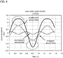
Fig. 4 shows oscillation waveforms when b = 0.20 and ϕ = 20.535 in this invention. -
Fig. 5 shows oscillation waveforms when b = 0.25 and ϕ = 24.46 in this invention. -
Fig. 6 shows the maximum frictional force per oscillation waveform. -
Fig. 1 is a cross sectional view showing an example of the structure of a continuous casting machine to which the operation method of this invention can be applied. Atundish 1 is stocked withmolten steel 6 supplied from a ladle not shown. Atubular mold 3 having an opening at each top and bottom thereof is arranged below thetundish 1. Themolten steel 6 is poured from thetundish 1 via theimmerged nozzle 2 into themold 3 through the opening at the top of themold 3. - An
oscillator 20 is connected to themold 3. Theoscillator 20 is electro-hydraulic, and can vertically oscillate themold 3. Theoscillator 20 includes a controlling part. Parameters of waveforms can be inputted to the controlling part. Theoscillator 20 can generate oscillation having various waveforms based on inputted parameters. Oscillation having a waveform generated by the way described above is applied to themold 3 during continuous casting. - Powder is put into the
molten steel 6 in themold 3. Powder melts with heat of themolten steel 6, to become molten powder, and spreads over the surface of themolten steel 6 in themold 3. In themolten steel 6, a contact portion with or a portion in the vicinity of a part facing themold 3 are cooled, solidified, to be a tubular solidifiedshell 7. The molten powder is supplied to a space between themold 3 and the solidifiedshell 7. Whereby, frictional force between themold 3 and the solidifiedshell 7 is decreased. - The inside of the solidified
shell 7 is filled with themolten steel 6. Themolten steel 6 is not completely solidified by passing through themold 3, to be an unsolidified slab including an unsolidified part. The unsolidified slab is cooled by cooling water jetted out of secondary cooling spray nozzles arranged below themold 3, which are not shown. Whereby, the solidifiedshell 7 enlarges. - As being supported by
foot rolls 4 arranged right under themold 3 and plural ofroller aprons 5 arranged in the downstream side of the foot rolls 4 in the direction where the unsolidified slab travels (hereinafter just referred to as "downstream side"), the unsolidified slab is withdrawn by pinch rolls 8 arranged in the downstream side of theroller aprons 5. The unsolidified slab is reduced byreduction rolls 9 arranged in the downstream side of the pinch rolls 8, to be a slab that does not substantially contain any unsolidified part. - As described above, in the method for operating a continuous casting machine of this invention, the mold oscillates with the oscillation waveform represented by the formula (1). While the waveform of the formula (X) in the prior art is a composite waveform that is the combination of only sine waves of different cycles, the waveform of the formula (1) is a composite waveform of a sine wave and a cosine wave. Further, the formula (1) is significantly different from the formula (X) in introduction of the initial phase ϕ and r(0) = 0.
- In the formula (1), let ϕ = 0. The displacement of the mold r(t) is the maximum value (S/2) when ωt = π/2, and is the minimum value (-S/2) when ωt = -π/2. The maximum value and the minimum value of the displacement of the mold r(t) do not depend on the initial phase ϕ. Thus, a neutral position does not shift in the oscillation waveform represented by the formula (1). Therefore, poor lubrication and involvement of powder into the molten steel can be prevented not only in vertical type continuous casting but also curved type continuous casting.
- The formula (3) below has to be satisfied in order for the displacement of the mold to be 0 when the time t = 0. The formula (3) below is obtained by substituting 0 for t, to be r(0) = 0 in the formula (1):

- Using the formula of a trigonometric function, cos2ϕ = 1 - 2sin2ϕ, the formula (3) can be rewritten into the formula (4) below:

- Since |sinϕ| ≤ 1, the following formula (5) is obtained if sinϕ is made to be the subject of the formula (4):

- If ϕ is made to be the subject of the formula (5) using the formulae of a trigonometric function, tanϕ = sinϕ/cosϕ and cosϕ = ±(1 - sin2ϕ)1/2, the above formula (2) is obtained.
- That is, satisfaction of the formula (2) makes the displacement of the mold r(0) 0 when the time t = 0. Therefore, it becomes possible to oscillate the mold with a predetermined oscillation waveform since the start of operation of the oscillator that oscillates the mold, and to well seal the opening of the mold with a dummy bar.
- Two values of ϕ are determined by the formula (2). If a direction of the movement of the mold at the start of oscillation is upward, ϕ that satisfies cosϕ > 0 may be employed since dr(0)/dt > 0.
- A non-sine coefficient b is any value within the range of 0 < b ≤ 0.25.
- "b" is a coefficient of cos2(ωt + ϕ) in the term of bcos2(ωt + ϕ), and determines magnitude of the term of bcos2(ωt + ϕ) to the term of sin(ωt + ϕ). In a case of 0.25 < b, the term of bcos2(ωt + ϕ) is too large compared to the term of sin(ωt + ϕ), which arises a problem that the mold descends when ωt + ϕ = π(1/2 + 2n) (n is 0 or a positive integer), where the mold should ascend most. Thus, b ≤ 0.25. For your reference,
Fig. 2 shows the waveforms when b = 0.4 and the initial phase ϕ = 33.66°. As shown inFig. 2 , in the case of b = 0.4 that satisfies 0.25 < b, the mold descends when ωt + ϕ = π(1/2 + 2n) (n is 0 or a positive integer), where the mold should ascend most. Therefore, in this invention, b ≤ 0.25. - On the other hand, when b is 0, the waveform of the displacement of the mold r(t) shows simple harmonic motion. In this case, compared with the case of 0 < b, the inflow of the molten powder into a space between the mold and the solidified shell cannot be increased. Thus, in this invention, 0 < b. Preferably 0.15 ≤ b in this invention in order to increase the inflow of the molten powder enough compared with the case of the simple harmonic motion.
- Table 1 shows values of the initial phase ϕ determined by the formula (2) in each case where the non-sine coefficient b is 0.15, 0.20 and 0.25. It makes r(0) = 0 possible that a value of the initial phase ϕ that satisfies the formula (2) is employed according to a value of the non-sine coefficient b.
[Table 1] Non-sine Coefficient (b) 0.15 0.20 0.25 Initial Phase (ϕ) 16.08 20.535 24.46 -
Figs. 3 to 5 show waveforms based on the formula (1) (relation between the time t and the displacement of the mold r(t)) when the combination shown in Table 1, that is, (b = 0.15, ϕ = 16.08), (b = 0.20, ϕ = 20.535), (b = 0.25, ϕ = 24.46) are employed as values of the non-sine coefficient b and the initial phase ϕ. - In
Figs. 3 to 5 , the part of sin(ωt + ϕ) in the formula (1) is shown as a primary waveform, the part of bcos2(ωt + ϕ) therein is shown as a secondary waveform, and r(t) therein is shown as a composite waveform, where S = 4 mm and ω = 2π rad/s. - In each composite waveform shown in
Figs. 3 to 5 , change in movement speed in the vicinity of the maximum displacement (peak) is small, and that in the vicinity of the minimum displacement (bottom) is large compared to the case where an oscillation waveform is a sine wave. As the non-sine coefficient b is larger, time when the change in movement speed in the vicinity of the maximum displacement is small is longer. The movement speed of the mold (ascending speed and descending speed) is fast during the time between the vicinity of the minimum displacement and the vicinity of the maximum displacement, compared to the case where an oscillation waveform is a sine wave. - The fast descending speed of the mold makes the amount of the molten powder that is pushed (pumped) into a space between the mold and the solidified shell increase. The fast ascending speed of the mold makes the powder possible to reach closer area to the inner wall surface of the mold (makes it possible to broaden the flow path of the powder). The long time when change in the movement speed of the mold in the vicinity of the maximum displacement is small makes it possible to keep the state where the flow path of the powder broadens long. Therefore, the lubricity between the mold and the solidified shell can be improved by vertical oscillation of the mold with any composite waveform shown in
Figs. 3 to 5 . - The displacement of the mold in the case of t = 0 is at the middle position between the maximum displacement (2 mm) and the minimum displacement (-2 mm), that is, at a neutral position in every composite waveform shown in
Figs. 3 to 5 . Whereby, troubles at the initial stage of casting such as seal leakage can be prevented. The neutral position does not shift. So, the effect of suppressing poor lubrication in the mold and involvement of the powder into the molten steel can be stably brought about. - While the lubricity between the mold and the solidified shell can be more improved as the non-sine coefficient b is larger, some kinds of physical properties of the powder cause the molten powder to be easily involved into the molten steel. In view of the above, preferably, a proper value of the non-sine coefficient b is employed according to physical properties of powder, or powder of proper physical properties is employed correspondingly to the value of the non-sine coefficient b. For example, when the value of the non-sine coefficient b is large, involvement of the molten powder into the molten steel can be suppressed efficiently if powder of a high solidification point, and in a molten state, of high viscosity is employed.
- Difference in performance of the lubricity of powder of different oscillation waveforms were examined. As oscillation waveforms, a sine wave, the waveform shown in
Fig. 3 (b = 0.15) and the waveform shown inFig. 5 (b = 0.25) were used. Continuous casting was carried out as a mold oscillated vertically with each waveform using an electro-hydraulic oscillator. The powder of the same properties (solidification point: 1154°C, viscosity of the molten powder at 1300°C: 0.14Pa·s) was used for every case where the mold oscillated with the above mentioned oscillation waveform. Load when the mold oscillated, which was the maximum load during the time when the mold ascended (hereinafter simply referred to as "max load"), was measured by the above electro-hydraulic oscillator. - The performance of the lubricity was evaluated by the maximum frictional force. The maximum frictional force F was represented by

- where L1 is the max load at the casting (when the molten steel existed in the mold);
- L2 is the max load when the casting was not carried out (when the molten steel did not exist in the mold; and
- S is an area of a part that touched or faced the molten steel in the inner face of the mold.
-
Fig. 6 shows the maximum frictional force for the oscillation waveforms. The maximum frictional force is small in the case the waveforms shown inFigs. 3 and5 were used as oscillation waveforms compared to the case where the sine wave is used. That is, the performance of the lubricity of the powder between the mold and the solidified shell was high in the case where the waveform of the formula (1) (b = 0.15, 0.25) compared to the case where the sine wave was used. The performance of the lubricity was higher in the case of b = 0.25 than the case of b = 0.15. -
- 3
- mold
- 20
- oscillator
Claims (2)
- A method for operating a continuous casting machine where a slab is withdrawn from a mold for continuous casting while the mold is oscillated in a vertical direction, the method comprising:oscillating the mold so as to satisfy the following formula (2) with an oscillation waveform represented by the following formula (1):

 wherein r(t) is displacement of the mold (mm),S is an oscillation stroke of the mold S (mm),ω is angular velocity (= 2πf) (rad/s),f is oscillation frequency of the mold (Hz),t is time (s),ϕ is the initial phase (°), andb is a non-sine coefficient (0 < b ≤ 0.25).
 - The method for operating a continuous casting machine according to claim 1, wherein 0.15 ≤ b.
Applications Claiming Priority (2)
| Application Number | Priority Date | Filing Date | Title |
|---|---|---|---|
| JP2014132848 | 2014-06-27 | ||
| PCT/JP2015/065085 WO2015198778A1 (en) | 2014-06-27 | 2015-05-26 | Method for operating continuous casting machine |
Publications (3)
| Publication Number | Publication Date |
|---|---|
| EP3162462A1 true EP3162462A1 (en) | 2017-05-03 |
| EP3162462A4 EP3162462A4 (en) | 2018-01-17 |
| EP3162462B1 EP3162462B1 (en) | 2020-03-04 |
Family
ID=54937875
Family Applications (1)
| Application Number | Title | Priority Date | Filing Date |
|---|---|---|---|
| EP15811824.0A Active EP3162462B1 (en) | 2014-06-27 | 2015-05-26 | Method for operating continuous casting machine |
Country Status (8)
| Country | Link |
|---|---|
| US (1) | US9999919B2 (en) |
| EP (1) | EP3162462B1 (en) |
| JP (1) | JP6249099B2 (en) |
| KR (1) | KR101906699B1 (en) |
| CN (1) | CN106457372B (en) |
| BR (1) | BR112016029948B1 (en) |
| TW (1) | TWI636839B (en) |
| WO (1) | WO2015198778A1 (en) |
Families Citing this family (6)
| Publication number | Priority date | Publication date | Assignee | Title |
|---|---|---|---|---|
| JP3197364B2 (en) | 1992-10-28 | 2001-08-13 | ホソカワミクロン株式会社 | Mixing device |
| CN109807293B (en) * | 2019-01-23 | 2020-10-27 | 王文章 | Vibration generating device and method for changing amplitude of continuous casting crystallizer through eccentric wheel |
| CN109807297B (en) * | 2019-02-27 | 2020-01-14 | 燕山大学 | Non-sinusoidal vibration method for continuous casting crystallizer |
| CN113878099B (en) * | 2021-10-12 | 2023-06-02 | 山东理工大学 | Method for inhibiting temperature downlink of reflux zone and double-roller casting and rolling system applying method |
| CN115570109B (en) * | 2022-09-30 | 2024-08-20 | 中冶赛迪信息技术(重庆)有限公司 | Non-sinusoidal vibration control method, device, equipment and medium for crystallizer |
| CN115488307B (en) * | 2022-09-30 | 2024-08-20 | 中冶赛迪信息技术(重庆)有限公司 | Crystallizer vibration control method, device, equipment and medium |
Family Cites Families (13)
| Publication number | Priority date | Publication date | Assignee | Title |
|---|---|---|---|---|
| JPS57112961A (en) * | 1980-12-29 | 1982-07-14 | Nippon Steel Corp | Method for measuring lubricating state beween mold and ingot continuous casting |
| JPH02197359A (en) * | 1989-01-26 | 1990-08-03 | Nippon Stainless Steel Co Ltd | Continuous casting method |
| JPH0479744A (en) | 1990-07-19 | 1992-03-13 | Canon Inc | Method of connecting winding of small-sized motor |
| JPH105956A (en) * | 1996-06-27 | 1998-01-13 | Kawasaki Steel Corp | Steel continuous casting method |
| ES2173581T3 (en) * | 1997-04-26 | 2002-10-16 | Sms Demag Ag | PROCEDURE FOR THE GENERATION OF THE OSCILLATION OF A FOUNDRY COQUILLA OF CONTINUOUS COLADA. |
| JP2000052009A (en) * | 1998-08-10 | 2000-02-22 | Sumitomo Heavy Ind Ltd | Mold vibration method in continuous casting |
| JP3651447B2 (en) * | 2002-04-09 | 2005-05-25 | 住友金属工業株式会社 | Operation method of continuous casting machine |
| CN1318163C (en) * | 2005-03-25 | 2007-05-30 | 燕山大学 | Servo motor driven continuous casting crystallizer non sine vibration generating arrangement |
| CN1799727A (en) * | 2005-08-29 | 2006-07-12 | 西安重型机械研究所 | Mathematical model of hydraulic non-sine oscillation trajectory for mold |
| CN101642801B (en) * | 2008-08-07 | 2011-08-24 | 上海重矿连铸技术工程有限公司 | Method for oscillating continuous casting mold |
| JP5272720B2 (en) * | 2008-12-25 | 2013-08-28 | 新日鐵住金株式会社 | Steel continuous casting method |
| CN101537477B (en) * | 2009-04-16 | 2010-12-08 | 中冶赛迪工程技术股份有限公司 | A non-sinusoidal waveform generator for crystallizer vibration |
| CN102120254B (en) * | 2010-01-08 | 2012-12-19 | 上海重矿连铸技术工程有限公司 | Direct-drive crystallizer vibration generating device |
-
2015
- 2015-05-26 EP EP15811824.0A patent/EP3162462B1/en active Active
- 2015-05-26 CN CN201580024536.XA patent/CN106457372B/en active Active
- 2015-05-26 US US15/312,678 patent/US9999919B2/en active Active
- 2015-05-26 KR KR1020167034037A patent/KR101906699B1/en active Active
- 2015-05-26 BR BR112016029948-5A patent/BR112016029948B1/en active IP Right Grant
- 2015-05-26 WO PCT/JP2015/065085 patent/WO2015198778A1/en not_active Ceased
- 2015-05-26 JP JP2016529201A patent/JP6249099B2/en active Active
- 2015-06-10 TW TW104118772A patent/TWI636839B/en not_active IP Right Cessation
Also Published As
| Publication number | Publication date |
|---|---|
| CN106457372A (en) | 2017-02-22 |
| CN106457372B (en) | 2018-09-07 |
| TWI636839B (en) | 2018-10-01 |
| KR20160149283A (en) | 2016-12-27 |
| JP6249099B2 (en) | 2017-12-20 |
| TW201607641A (en) | 2016-03-01 |
| BR112016029948A2 (en) | 2017-08-22 |
| EP3162462A4 (en) | 2018-01-17 |
| WO2015198778A1 (en) | 2015-12-30 |
| US20170182550A1 (en) | 2017-06-29 |
| US9999919B2 (en) | 2018-06-19 |
| EP3162462B1 (en) | 2020-03-04 |
| KR101906699B1 (en) | 2018-10-10 |
| BR112016029948B1 (en) | 2021-03-09 |
| JPWO2015198778A1 (en) | 2017-04-20 |
Similar Documents
| Publication | Publication Date | Title |
|---|---|---|
| EP3162462B1 (en) | Method for operating continuous casting machine | |
| Takeuchi et al. | The formation of oscillation marks in the continuous casting of steel slabs | |
| JP6874528B2 (en) | Continuous casting method of slabs | |
| US6336496B1 (en) | Apparatus for continuous casting of metal | |
| CA2004841C (en) | Method for oscillation of mold of vertical continuous caster | |
| JP5829971B2 (en) | Vibrating mold for continuous casting, method for setting preset force of coil spring provided therein, and method for preventing breakout in continuous casting | |
| JP5712685B2 (en) | Continuous casting method | |
| JP6318848B2 (en) | Vibration apparatus for continuous casting mold and continuous casting method | |
| KR960040509A (en) | Continuous casting method and apparatus of steel | |
| JPH02207945A (en) | Mold for continuous casting of round cast billet | |
| JPH0243574B2 (en) | ||
| EP0618023B1 (en) | casting continuous slab in oscillated mold with horizontally retractable walls | |
| JP4719360B2 (en) | Metal continuous casting method and apparatus | |
| JPH0356824B2 (en) | ||
| JPH11291000A (en) | Continuous casting, particularly, steel continuous casting equipment | |
| JP4910357B2 (en) | Steel continuous casting method | |
| JPH105945A (en) | Method for controlling molten steel flow in continuous casting mold | |
| JP6733336B2 (en) | Continuous casting machine and continuous casting method | |
| JPH0857591A (en) | Continuous casting method | |
| JP2010188375A (en) | Casting mold equipment for continuous casting of metal and continuous casting method | |
| JPS63104759A (en) | Molten metal injection device | |
| JPS62179854A (en) | Continuous casting method for steel | |
| WO1994006583A1 (en) | Method of casting continuous slab | |
| JPH09234549A (en) | Vibration control method for continuous casting mold | |
| JP2013094796A (en) | Method for manufacturing high-cleanliness steel cast slab by continuous casting |
Legal Events
| Date | Code | Title | Description |
|---|---|---|---|
| STAA | Information on the status of an ep patent application or granted ep patent |
Free format text: STATUS: THE INTERNATIONAL PUBLICATION HAS BEEN MADE |
|
| PUAI | Public reference made under article 153(3) epc to a published international application that has entered the european phase |
Free format text: ORIGINAL CODE: 0009012 |
|
| STAA | Information on the status of an ep patent application or granted ep patent |
Free format text: STATUS: REQUEST FOR EXAMINATION WAS MADE |
|
| 17P | Request for examination filed |
Effective date: 20161128 |
|
| AK | Designated contracting states |
Kind code of ref document: A1 Designated state(s): AL AT BE BG CH CY CZ DE DK EE ES FI FR GB GR HR HU IE IS IT LI LT LU LV MC MK MT NL NO PL PT RO RS SE SI SK SM TR |
|
| AX | Request for extension of the european patent |
Extension state: BA ME |
|
| DAV | Request for validation of the european patent (deleted) | ||
| DAX | Request for extension of the european patent (deleted) | ||
| A4 | Supplementary search report drawn up and despatched |
Effective date: 20171215 |
|
| RIC1 | Information provided on ipc code assigned before grant |
Ipc: B22D 11/16 20060101AFI20171211BHEP |
|
| STAA | Information on the status of an ep patent application or granted ep patent |
Free format text: STATUS: EXAMINATION IS IN PROGRESS |
|
| 17Q | First examination report despatched |
Effective date: 20180613 |
|
| RAP1 | Party data changed (applicant data changed or rights of an application transferred) |
Owner name: NIPPON STEEL CORPORATION |
|
| RIC1 | Information provided on ipc code assigned before grant |
Ipc: B22D 11/041 20060101ALI20190731BHEP Ipc: B22D 11/051 20060101ALI20190731BHEP Ipc: B22D 11/16 20060101AFI20190731BHEP |
|
| GRAP | Despatch of communication of intention to grant a patent |
Free format text: ORIGINAL CODE: EPIDOSNIGR1 |
|
| STAA | Information on the status of an ep patent application or granted ep patent |
Free format text: STATUS: GRANT OF PATENT IS INTENDED |
|
| INTG | Intention to grant announced |
Effective date: 20190910 |
|
| GRAS | Grant fee paid |
Free format text: ORIGINAL CODE: EPIDOSNIGR3 |
|
| GRAA | (expected) grant |
Free format text: ORIGINAL CODE: 0009210 |
|
| STAA | Information on the status of an ep patent application or granted ep patent |
Free format text: STATUS: THE PATENT HAS BEEN GRANTED |
|
| AK | Designated contracting states |
Kind code of ref document: B1 Designated state(s): AL AT BE BG CH CY CZ DE DK EE ES FI FR GB GR HR HU IE IS IT LI LT LU LV MC MK MT NL NO PL PT RO RS SE SI SK SM TR |
|
| REG | Reference to a national code |
Ref country code: GB Ref legal event code: FG4D |
|
| REG | Reference to a national code |
Ref country code: CH Ref legal event code: EP |
|
| REG | Reference to a national code |
Ref country code: AT Ref legal event code: REF Ref document number: 1239806 Country of ref document: AT Kind code of ref document: T Effective date: 20200315 |
|
| REG | Reference to a national code |
Ref country code: DE Ref legal event code: R096 Ref document number: 602015048277 Country of ref document: DE |
|
| REG | Reference to a national code |
Ref country code: NL Ref legal event code: FP Ref country code: IE Ref legal event code: FG4D |
|
| REG | Reference to a national code |
Ref country code: SE Ref legal event code: TRGR |
|
| PG25 | Lapsed in a contracting state [announced via postgrant information from national office to epo] |
Ref country code: FI Free format text: LAPSE BECAUSE OF FAILURE TO SUBMIT A TRANSLATION OF THE DESCRIPTION OR TO PAY THE FEE WITHIN THE PRESCRIBED TIME-LIMIT Effective date: 20200304 Ref country code: RS Free format text: LAPSE BECAUSE OF FAILURE TO SUBMIT A TRANSLATION OF THE DESCRIPTION OR TO PAY THE FEE WITHIN THE PRESCRIBED TIME-LIMIT Effective date: 20200304 Ref country code: NO Free format text: LAPSE BECAUSE OF FAILURE TO SUBMIT A TRANSLATION OF THE DESCRIPTION OR TO PAY THE FEE WITHIN THE PRESCRIBED TIME-LIMIT Effective date: 20200604 |
|
| PGFP | Annual fee paid to national office [announced via postgrant information from national office to epo] |
Ref country code: NL Payment date: 20200527 Year of fee payment: 6 Ref country code: LU Payment date: 20200520 Year of fee payment: 6 Ref country code: FR Payment date: 20200522 Year of fee payment: 6 Ref country code: TR Payment date: 20200521 Year of fee payment: 6 Ref country code: DE Payment date: 20200520 Year of fee payment: 6 |
|
| PG25 | Lapsed in a contracting state [announced via postgrant information from national office to epo] |
Ref country code: LV Free format text: LAPSE BECAUSE OF FAILURE TO SUBMIT A TRANSLATION OF THE DESCRIPTION OR TO PAY THE FEE WITHIN THE PRESCRIBED TIME-LIMIT Effective date: 20200304 Ref country code: BG Free format text: LAPSE BECAUSE OF FAILURE TO SUBMIT A TRANSLATION OF THE DESCRIPTION OR TO PAY THE FEE WITHIN THE PRESCRIBED TIME-LIMIT Effective date: 20200604 Ref country code: GR Free format text: LAPSE BECAUSE OF FAILURE TO SUBMIT A TRANSLATION OF THE DESCRIPTION OR TO PAY THE FEE WITHIN THE PRESCRIBED TIME-LIMIT Effective date: 20200605 Ref country code: HR Free format text: LAPSE BECAUSE OF FAILURE TO SUBMIT A TRANSLATION OF THE DESCRIPTION OR TO PAY THE FEE WITHIN THE PRESCRIBED TIME-LIMIT Effective date: 20200304 |
|
| PGFP | Annual fee paid to national office [announced via postgrant information from national office to epo] |
Ref country code: GB Payment date: 20200527 Year of fee payment: 6 Ref country code: BE Payment date: 20200527 Year of fee payment: 6 Ref country code: IT Payment date: 20200529 Year of fee payment: 6 Ref country code: SE Payment date: 20200527 Year of fee payment: 6 |
|
| REG | Reference to a national code |
Ref country code: LT Ref legal event code: MG4D |
|
| PGFP | Annual fee paid to national office [announced via postgrant information from national office to epo] |
Ref country code: AT Payment date: 20200522 Year of fee payment: 6 |
|
| PG25 | Lapsed in a contracting state [announced via postgrant information from national office to epo] |
Ref country code: SK Free format text: LAPSE BECAUSE OF FAILURE TO SUBMIT A TRANSLATION OF THE DESCRIPTION OR TO PAY THE FEE WITHIN THE PRESCRIBED TIME-LIMIT Effective date: 20200304 Ref country code: SM Free format text: LAPSE BECAUSE OF FAILURE TO SUBMIT A TRANSLATION OF THE DESCRIPTION OR TO PAY THE FEE WITHIN THE PRESCRIBED TIME-LIMIT Effective date: 20200304 Ref country code: EE Free format text: LAPSE BECAUSE OF FAILURE TO SUBMIT A TRANSLATION OF THE DESCRIPTION OR TO PAY THE FEE WITHIN THE PRESCRIBED TIME-LIMIT Effective date: 20200304 Ref country code: IS Free format text: LAPSE BECAUSE OF FAILURE TO SUBMIT A TRANSLATION OF THE DESCRIPTION OR TO PAY THE FEE WITHIN THE PRESCRIBED TIME-LIMIT Effective date: 20200704 Ref country code: ES Free format text: LAPSE BECAUSE OF FAILURE TO SUBMIT A TRANSLATION OF THE DESCRIPTION OR TO PAY THE FEE WITHIN THE PRESCRIBED TIME-LIMIT Effective date: 20200304 Ref country code: PT Free format text: LAPSE BECAUSE OF FAILURE TO SUBMIT A TRANSLATION OF THE DESCRIPTION OR TO PAY THE FEE WITHIN THE PRESCRIBED TIME-LIMIT Effective date: 20200729 Ref country code: LT Free format text: LAPSE BECAUSE OF FAILURE TO SUBMIT A TRANSLATION OF THE DESCRIPTION OR TO PAY THE FEE WITHIN THE PRESCRIBED TIME-LIMIT Effective date: 20200304 Ref country code: RO Free format text: LAPSE BECAUSE OF FAILURE TO SUBMIT A TRANSLATION OF THE DESCRIPTION OR TO PAY THE FEE WITHIN THE PRESCRIBED TIME-LIMIT Effective date: 20200304 Ref country code: CZ Free format text: LAPSE BECAUSE OF FAILURE TO SUBMIT A TRANSLATION OF THE DESCRIPTION OR TO PAY THE FEE WITHIN THE PRESCRIBED TIME-LIMIT Effective date: 20200304 |
|
| REG | Reference to a national code |
Ref country code: DE Ref legal event code: R097 Ref document number: 602015048277 Country of ref document: DE |
|
| PLBE | No opposition filed within time limit |
Free format text: ORIGINAL CODE: 0009261 |
|
| STAA | Information on the status of an ep patent application or granted ep patent |
Free format text: STATUS: NO OPPOSITION FILED WITHIN TIME LIMIT |
|
| PG25 | Lapsed in a contracting state [announced via postgrant information from national office to epo] |
Ref country code: MC Free format text: LAPSE BECAUSE OF FAILURE TO SUBMIT A TRANSLATION OF THE DESCRIPTION OR TO PAY THE FEE WITHIN THE PRESCRIBED TIME-LIMIT Effective date: 20200304 Ref country code: LI Free format text: LAPSE BECAUSE OF NON-PAYMENT OF DUE FEES Effective date: 20200531 Ref country code: DK Free format text: LAPSE BECAUSE OF FAILURE TO SUBMIT A TRANSLATION OF THE DESCRIPTION OR TO PAY THE FEE WITHIN THE PRESCRIBED TIME-LIMIT Effective date: 20200304 Ref country code: CH Free format text: LAPSE BECAUSE OF NON-PAYMENT OF DUE FEES Effective date: 20200531 |
|
| 26N | No opposition filed |
Effective date: 20201207 |
|
| PG25 | Lapsed in a contracting state [announced via postgrant information from national office to epo] |
Ref country code: PL Free format text: LAPSE BECAUSE OF FAILURE TO SUBMIT A TRANSLATION OF THE DESCRIPTION OR TO PAY THE FEE WITHIN THE PRESCRIBED TIME-LIMIT Effective date: 20200304 Ref country code: SI Free format text: LAPSE BECAUSE OF FAILURE TO SUBMIT A TRANSLATION OF THE DESCRIPTION OR TO PAY THE FEE WITHIN THE PRESCRIBED TIME-LIMIT Effective date: 20200304 |
|
| PG25 | Lapsed in a contracting state [announced via postgrant information from national office to epo] |
Ref country code: IE Free format text: LAPSE BECAUSE OF NON-PAYMENT OF DUE FEES Effective date: 20200526 |
|
| REG | Reference to a national code |
Ref country code: DE Ref legal event code: R119 Ref document number: 602015048277 Country of ref document: DE |
|
| REG | Reference to a national code |
Ref country code: SE Ref legal event code: EUG |
|
| REG | Reference to a national code |
Ref country code: NL Ref legal event code: MM Effective date: 20210601 |
|
| REG | Reference to a national code |
Ref country code: AT Ref legal event code: MM01 Ref document number: 1239806 Country of ref document: AT Kind code of ref document: T Effective date: 20210526 |
|
| GBPC | Gb: european patent ceased through non-payment of renewal fee |
Effective date: 20210526 |
|
| PG25 | Lapsed in a contracting state [announced via postgrant information from national office to epo] |
Ref country code: SE Free format text: LAPSE BECAUSE OF NON-PAYMENT OF DUE FEES Effective date: 20210527 Ref country code: AT Free format text: LAPSE BECAUSE OF NON-PAYMENT OF DUE FEES Effective date: 20210526 Ref country code: LU Free format text: LAPSE BECAUSE OF NON-PAYMENT OF DUE FEES Effective date: 20210526 |
|
| REG | Reference to a national code |
Ref country code: BE Ref legal event code: MM Effective date: 20210531 |
|
| PG25 | Lapsed in a contracting state [announced via postgrant information from national office to epo] |
Ref country code: GB Free format text: LAPSE BECAUSE OF NON-PAYMENT OF DUE FEES Effective date: 20210526 Ref country code: DE Free format text: LAPSE BECAUSE OF NON-PAYMENT OF DUE FEES Effective date: 20211201 |
|
| PG25 | Lapsed in a contracting state [announced via postgrant information from national office to epo] |
Ref country code: MT Free format text: LAPSE BECAUSE OF FAILURE TO SUBMIT A TRANSLATION OF THE DESCRIPTION OR TO PAY THE FEE WITHIN THE PRESCRIBED TIME-LIMIT Effective date: 20200304 Ref country code: FR Free format text: LAPSE BECAUSE OF NON-PAYMENT OF DUE FEES Effective date: 20210531 Ref country code: CY Free format text: LAPSE BECAUSE OF FAILURE TO SUBMIT A TRANSLATION OF THE DESCRIPTION OR TO PAY THE FEE WITHIN THE PRESCRIBED TIME-LIMIT Effective date: 20200304 Ref country code: NL Free format text: LAPSE BECAUSE OF NON-PAYMENT OF DUE FEES Effective date: 20210601 |
|
| PG25 | Lapsed in a contracting state [announced via postgrant information from national office to epo] |
Ref country code: MK Free format text: LAPSE BECAUSE OF FAILURE TO SUBMIT A TRANSLATION OF THE DESCRIPTION OR TO PAY THE FEE WITHIN THE PRESCRIBED TIME-LIMIT Effective date: 20200304 Ref country code: AL Free format text: LAPSE BECAUSE OF FAILURE TO SUBMIT A TRANSLATION OF THE DESCRIPTION OR TO PAY THE FEE WITHIN THE PRESCRIBED TIME-LIMIT Effective date: 20200304 |
|
| PG25 | Lapsed in a contracting state [announced via postgrant information from national office to epo] |
Ref country code: BE Free format text: LAPSE BECAUSE OF NON-PAYMENT OF DUE FEES Effective date: 20210531 |
|
| REG | Reference to a national code |
Ref country code: AT Ref legal event code: UEP Ref document number: 1239806 Country of ref document: AT Kind code of ref document: T Effective date: 20200304 |
|
| PG25 | Lapsed in a contracting state [announced via postgrant information from national office to epo] |
Ref country code: IT Free format text: LAPSE BECAUSE OF NON-PAYMENT OF DUE FEES Effective date: 20200526 |
|
| PG25 | Lapsed in a contracting state [announced via postgrant information from national office to epo] |
Ref country code: IT Free format text: LAPSE BECAUSE OF NON-PAYMENT OF DUE FEES Effective date: 20210526 |