EP3162345A1 - Nursing bed - Google Patents
Nursing bed Download PDFInfo
- Publication number
- EP3162345A1 EP3162345A1 EP15811838.0A EP15811838A EP3162345A1 EP 3162345 A1 EP3162345 A1 EP 3162345A1 EP 15811838 A EP15811838 A EP 15811838A EP 3162345 A1 EP3162345 A1 EP 3162345A1
- Authority
- EP
- European Patent Office
- Prior art keywords
- bed
- movable member
- driving unit
- movable
- nursing bed
- Prior art date
- Legal status (The legal status is an assumption and is not a legal conclusion. Google has not performed a legal analysis and makes no representation as to the accuracy of the status listed.)
- Granted
Links
Images














Classifications
-
- A—HUMAN NECESSITIES
- A61—MEDICAL OR VETERINARY SCIENCE; HYGIENE
- A61G—TRANSPORT, PERSONAL CONVEYANCES OR ACCOMMODATION SPECIALLY ADAPTED FOR PATIENTS OR DISABLED PERSONS; OPERATING TABLES OR CHAIRS; CHAIRS FOR DENTISTRY; FUNERAL DEVICES
- A61G7/00—Beds specially adapted for nursing; Devices for lifting patients or disabled persons
- A61G7/002—Beds specially adapted for nursing; Devices for lifting patients or disabled persons having adjustable mattress frame
- A61G7/018—Control or drive mechanisms
-
- A—HUMAN NECESSITIES
- A61—MEDICAL OR VETERINARY SCIENCE; HYGIENE
- A61G—TRANSPORT, PERSONAL CONVEYANCES OR ACCOMMODATION SPECIALLY ADAPTED FOR PATIENTS OR DISABLED PERSONS; OPERATING TABLES OR CHAIRS; CHAIRS FOR DENTISTRY; FUNERAL DEVICES
- A61G7/00—Beds specially adapted for nursing; Devices for lifting patients or disabled persons
- A61G7/002—Beds specially adapted for nursing; Devices for lifting patients or disabled persons having adjustable mattress frame
- A61G7/005—Beds specially adapted for nursing; Devices for lifting patients or disabled persons having adjustable mattress frame tiltable around transverse horizontal axis, e.g. for Trendelenburg position
-
- A—HUMAN NECESSITIES
- A61—MEDICAL OR VETERINARY SCIENCE; HYGIENE
- A61G—TRANSPORT, PERSONAL CONVEYANCES OR ACCOMMODATION SPECIALLY ADAPTED FOR PATIENTS OR DISABLED PERSONS; OPERATING TABLES OR CHAIRS; CHAIRS FOR DENTISTRY; FUNERAL DEVICES
- A61G7/00—Beds specially adapted for nursing; Devices for lifting patients or disabled persons
- A61G7/002—Beds specially adapted for nursing; Devices for lifting patients or disabled persons having adjustable mattress frame
- A61G7/015—Beds specially adapted for nursing; Devices for lifting patients or disabled persons having adjustable mattress frame divided into different adjustable sections, e.g. for Gatch position
-
- A—HUMAN NECESSITIES
- A61—MEDICAL OR VETERINARY SCIENCE; HYGIENE
- A61G—TRANSPORT, PERSONAL CONVEYANCES OR ACCOMMODATION SPECIALLY ADAPTED FOR PATIENTS OR DISABLED PERSONS; OPERATING TABLES OR CHAIRS; CHAIRS FOR DENTISTRY; FUNERAL DEVICES
- A61G7/00—Beds specially adapted for nursing; Devices for lifting patients or disabled persons
- A61G7/05—Parts, details or accessories of beds
-
- A—HUMAN NECESSITIES
- A61—MEDICAL OR VETERINARY SCIENCE; HYGIENE
- A61G—TRANSPORT, PERSONAL CONVEYANCES OR ACCOMMODATION SPECIALLY ADAPTED FOR PATIENTS OR DISABLED PERSONS; OPERATING TABLES OR CHAIRS; CHAIRS FOR DENTISTRY; FUNERAL DEVICES
- A61G7/00—Beds specially adapted for nursing; Devices for lifting patients or disabled persons
- A61G7/05—Parts, details or accessories of beds
- A61G7/057—Arrangements for preventing bed-sores or for supporting patients with burns, e.g. mattresses specially adapted therefor
-
- A—HUMAN NECESSITIES
- A61—MEDICAL OR VETERINARY SCIENCE; HYGIENE
- A61G—TRANSPORT, PERSONAL CONVEYANCES OR ACCOMMODATION SPECIALLY ADAPTED FOR PATIENTS OR DISABLED PERSONS; OPERATING TABLES OR CHAIRS; CHAIRS FOR DENTISTRY; FUNERAL DEVICES
- A61G7/00—Beds specially adapted for nursing; Devices for lifting patients or disabled persons
- A61G7/05—Parts, details or accessories of beds
- A61G7/057—Arrangements for preventing bed-sores or for supporting patients with burns, e.g. mattresses specially adapted therefor
- A61G7/05707—Arrangements for preventing bed-sores or for supporting patients with burns, e.g. mattresses specially adapted therefor with integral, body-bearing projections or protuberances
-
- A—HUMAN NECESSITIES
- A61—MEDICAL OR VETERINARY SCIENCE; HYGIENE
- A61G—TRANSPORT, PERSONAL CONVEYANCES OR ACCOMMODATION SPECIALLY ADAPTED FOR PATIENTS OR DISABLED PERSONS; OPERATING TABLES OR CHAIRS; CHAIRS FOR DENTISTRY; FUNERAL DEVICES
- A61G7/00—Beds specially adapted for nursing; Devices for lifting patients or disabled persons
- A61G7/10—Devices for lifting patients or disabled persons, e.g. special adaptations of hoists thereto
- A61G7/1025—Lateral movement of patients, e.g. horizontal transfer
-
- B—PERFORMING OPERATIONS; TRANSPORTING
- B25—HAND TOOLS; PORTABLE POWER-DRIVEN TOOLS; MANIPULATORS
- B25J—MANIPULATORS; CHAMBERS PROVIDED WITH MANIPULATION DEVICES
- B25J11/00—Manipulators not otherwise provided for
- B25J11/008—Manipulators for service tasks
- B25J11/009—Nursing, e.g. carrying sick persons, pushing wheelchairs, distributing drugs
-
- B—PERFORMING OPERATIONS; TRANSPORTING
- B25—HAND TOOLS; PORTABLE POWER-DRIVEN TOOLS; MANIPULATORS
- B25J—MANIPULATORS; CHAMBERS PROVIDED WITH MANIPULATION DEVICES
- B25J9/00—Program-controlled manipulators
- B25J9/0009—Constructional details, e.g. manipulator supports, bases
-
- A—HUMAN NECESSITIES
- A61—MEDICAL OR VETERINARY SCIENCE; HYGIENE
- A61G—TRANSPORT, PERSONAL CONVEYANCES OR ACCOMMODATION SPECIALLY ADAPTED FOR PATIENTS OR DISABLED PERSONS; OPERATING TABLES OR CHAIRS; CHAIRS FOR DENTISTRY; FUNERAL DEVICES
- A61G2203/00—General characteristics of devices
- A61G2203/30—General characteristics of devices characterised by sensor means
- A61G2203/42—General characteristics of devices characterised by sensor means for inclination
-
- A—HUMAN NECESSITIES
- A61—MEDICAL OR VETERINARY SCIENCE; HYGIENE
- A61G—TRANSPORT, PERSONAL CONVEYANCES OR ACCOMMODATION SPECIALLY ADAPTED FOR PATIENTS OR DISABLED PERSONS; OPERATING TABLES OR CHAIRS; CHAIRS FOR DENTISTRY; FUNERAL DEVICES
- A61G7/00—Beds specially adapted for nursing; Devices for lifting patients or disabled persons
- A61G7/002—Beds specially adapted for nursing; Devices for lifting patients or disabled persons having adjustable mattress frame
- A61G7/008—Beds specially adapted for nursing; Devices for lifting patients or disabled persons having adjustable mattress frame tiltable around longitudinal axis, e.g. for rolling
Definitions
- the present invention relates to a nursing bed and particularly relates to a nursing bed capable of moving the body of a care receiver lying on the bed.
- Bedsores occur especially in protruding parts with bones such as the waist, shoulders, and ankles because of poor blood circulation due to pressure of the body weight, resulting in necrosis.
- Posture of a care receiver needs to be changed appropriately in order to prevent bedsores, and in particular when the care receiver has difficulty moving his/her body by himself/herself, a caregiver needs to take appropriate measures such as putting a pillow under the waist of the care receiver.
- the caregiver needs to move a heavy body of the care receiver in order to prevent bedsores, which is a hard work. Moreover, the work needs to be done night and day, for example every one or two hours, which is a heavy burden for the caregiver. Additionally, the care receiver also tends to feel a mental burden about forcing a hard work on the caregiver.
- the whole body of a care receiver is merely slid simultaneously on a bed portion of a bed, or a part (for example, a part corresponding to the upper body) of the bed surface of the bed is merely inclined so as to support the posture of the care receiver on the inclined bed surface of the bed, or alternatively, an unnatural strong force is applied locally when moving the body of the care receiver, imposing a burden on the body of the care receiver.
- a posture changing mechanism cannot be appropriately added to especially a portion where bedsores need to be prevented according to types of care receivers (severely ill in legs, severely ill in the waist, or the like).
- the present invention is made considering the above-mentioned problems of the conventional technology and its object is to provide a nursing bed capable of changing the posture of a care receiver lying on the bed into his/her optimal position without difficulty.
- the present invention according to a first aspect is a nursing bed with a dimension in a longitudinal direction and a dimension in a lateral direction, comprising: a fixed member forming a fixed bed surface of a bed portion on which a care receiver lies; a movable member which can be moved relative to the fixed member and forms a movable bed surface of the bed portion; and a movable member driving unit for driving the movable member, wherein the fixed member has a plurality of slender parts each extending in the lateral direction or the longitudinal direction, and wherein the movable member has a mobile body which can be protruded upward relative to the fixed bed surface and also moved in at least one of the longitudinal direction and the lateral direction via an interval between the plurality of slender parts by the movable member driving unit.
- the present invention according to a second aspect is that, in the present invention according to the first aspect, the fixed member further has a plurality of additional slender parts each extending in the longitudinal direction or the lateral direction, wherein the fixed member is formed in a lattice shape by the plurality of slender parts and the plurality of additional slender parts.
- the present invention according to a third aspect is that, in the present invention according to the first or second aspect, the movable member has the plurality of mobile bodies, wherein the movable member driving unit can make the plurality of mobile bodies move simultaneously.
- the present invention according to a fourth aspect is that, in the present invention according to any one of the first to third aspects, the movable member has the plurality of mobile bodies, wherein the movable member driving unit can make the plurality of mobile bodies move independently from each other.
- the present invention according to a fifth aspect is that, in the present invention according to any one of the first to fourth aspects, the movable member driving unit is configured such that a rotational driving force is transmitted from a rotational driver mounted to a distal end portion of a robot arm.
- the present invention according to a sixth aspect is that, in the present invention according to the fifth aspect, the movable member driving unit has a plurality of rotated drivers selectively and separably connected to the rotational driver, and the plurality of rotated drivers are installed corresponding to motions of the movable members different from each other, respectively.
- the present invention according to a seventh aspect is that, in the present invention according to any one of the first to sixth aspects, the movable member is arranged such that the movable bed surface is normally positioned at the same level as the fixed bed surface or at a level lower than the fixed bed surface.
- the present invention is a nursing bed with a dimension in a longitudinal direction and a dimension in a lateral direction, comprising: a bed portion on which a care receiver lies, having a plurality of bed portion units which can be moved so as to be inclined independently from each other; and a bed portion unit driving unit for driving the plurality of bed portion units so as to be inclined independently from each other, wherein each of the plurality of bed portion units has a fixed member forming a fixed bed surface of the bed portion unit; a movable member which can be moved relative to the fixed member and forms a movable bed surface of the bed portion unit; and a movable member driving unit for driving the movable member, and wherein the movable member has a mobile body which can be protruded upward relative to the fixed bed surface and also moved in at least one of the longitudinal direction and the lateral direction via an opening formed in the fixed member by the movable member driving unit.
- the present invention according to a ninth aspect is that, in the present invention according to the eighth aspect, in at least one bed portion unit of the plurality of bed portion units, the movable member driving unit can make the mobile body rotationally move about an axis in the longitudinal direction or an axis in the lateral direction.
- the present invention according to a tenth aspect is that, in the present invention according to the eighth or ninth aspect, at least one bed portion unit of the plurality of bed portion units has the plurality of mobile bodies, wherein the movable member driving unit can make the plurality of mobile bodies move independently from each other.
- the present invention according to an eleventh aspect is that, in the present invention according to the eighth or ninth aspect, at least one bed portion unit of the plurality of bed portion units has the plurality of mobile bodies, wherein the movable member driving unit can make the plurality of mobile bodies belonging to the common bed portion unit move simultaneously.
- each of at least two bed portion units of the plurality of bed portion units has the plurality of mobile bodies, wherein the movable member driving unit can make the plurality of mobile bodies belonging to one of the at least two bed portion units perform a motion different from the plurality of mobile bodies belonging to the other one of the at least two bed portion units.
- the present invention according to a thirteenth aspect is that, in the present invention according to any one of the eighth to twelfth aspects, at least one of the bed portion unit driving unit and the movable member driving unit is configured such that a rotational driving force is transmitted from a rotational driver mounted to a distal end portion of a robot arm.
- the present invention according to a fourteenth aspect is that, in the present invention according to the thirteenth aspect, at least one of the bed portion unit driving unit and the movable member driving unit has a plurality of rotated drivers selectively and separably connected to the rotational driver, and the plurality of rotated drivers are installed corresponding to motions of the bed portion unit and/or the movable members different from each other, respectively.
- the present invention according to a fifteenth aspect is that, in the preset invention according to any one of the eighth to fourteenth aspects, the movable member is arranged such that the movable bed surface is normally positioned at the same level as the fixed bed surface or at a level lower than the fixed bed surface.
- the present invention according to a sixteenth aspect is a nursing bed having a bed portion on which a care receiver lies, comprising: a movable member forming at least a part of the bed portion; a movable member driving unit for making the movable member move; a posture information acquisition unit for acquiring a posture information about a posture of the care receiver lying on the bed portion; and a control unit for controlling the movable member driving unit based on the posture information acquired by the posture information acquisition unit so as to change the posture of the care receiver into a predetermined posture by a motion of the movable member.
- the present invention according to a seventeenth aspect is that, in the present invention according to the sixteenth aspect, the control unit analyzes a current posture information acquired by the posture information acquisition unit and a posture information of the predetermined posture as a target, and makes the movable member move multiple times so as to gradually make a difference between the current posture and the predetermined posture of the care receiver smaller.
- the present invention according to an eighteenth aspect is that, in the present invention according to the sixteenth or seventeenth aspect, the posture information acquisition unit acquires the posture information by imaging the care receiver.
- the present invention according to a nineteenth aspect is that, in the present invention according to any one of the sixteenth to eighteenth aspects, the movable member driving unit is configured such that a rotational driving force is transmitted from a rotational driver mounted to a distal end portion of a robot arm.
- the present invention according to a twentieth aspect is that, in the present invention according to the nineteenth aspect, the movable member driving unit has a plurality of rotated drivers selectively and separably connected to the rotational driver, and the plurality of rotated drivers are installed corresponding to motions of the movable members different from each other, respectively.
- the present invention according to a twenty-first aspect is that, in the present invention according to any one of the sixteenth to twentieth aspects, the movable member is arranged such that the movable bed surface is normally positioned at the same level as the fixed bed surface or at a level lower than the fixed bed surface.
- the present invention according to a twenty-second aspect is a nursing bed having a bed portion on which a care receiver lies, comprising: a movable member forming at least a part of the bed portion; and a movable member driving unit for making the movable member move; the nursing bed being configured as a module type such that the movable member and the movable member driving unit can be detachably mounted to a desired position of the whole bed portion.
- the present invention according to a twenty-third aspect is that, in the present invention according to the twenty-second aspect, the movable member driving unit is configured such that a rotational driving force is transmitted from a rotational driver mounted to a distal end portion of a robot arm.
- the present invention according to a twenty-fourth aspect is that, in the present invention according to the twenty-third aspect, the movable member driving unit has a plurality of rotated drivers selectively and separably connected to the rotational driver, and the plurality of rotated drivers are installed corresponding to motions of the movable members different from each other, respectively.
- the present invention according to a twenty-fifth aspect is that, in the present invention according to any one of the twenty-second to twenty-fourth aspects, the movable member is arranged such that the movable bed surface is normally positioned at the same level as the fixed bed surface or at a level lower than the fixed bed surface.
- the present invention is a nursing bed having a bed portion on which a care receiver lies, comprising: a movable member forming at least a part of the bed portion; and a movable member driving unit for making the movable member move; wherein the movable member driving unit is configured such that a rotational driving force is transmitted from a rotational driver mounted to a distal end portion of a robot arm, wherein the movable member driving unit has a plurality of rotated drivers selectively and separably connected to the rotational driver, and wherein the plurality of rotated drivers are installed corresponding to motions of the movable members different from each other, respectively.
- the posture of a care receiver lying on the bed can be changed into his/her optimal position without difficulty.
- a nursing bed 1 has a dimension L in the longitudinal direction and a dimension W in the lateral direction.
- the longitudinal dimension L and the lateral dimension W correspond to a longitudinal dimension and a lateral dimension of a bed portion 3 forming a bed surface 2 on which a care receiver P lies.
- the bed portion 3 is arranged above a bed base 4, and a driving mechanism 5 for moving at least a part of the bed portion 3 is provided to the bed base 4. At least a part of the driving mechanism 5 corresponds to a movable member driving unit in the present invention.
- the bed portion 3 of the nursing bed 1 is divided into a head region 8, a shoulder region 9, a waist region 10, and a leg region 11 along the longitudinal direction.
- the head region 8 of the bed portion 3 is formed of an integrated plate-like square member 12.
- the shoulder region 9 and the waist region 10 in the center portion in the longitudinal direction of the bed portion 3 comprise a fixed member 13A forming a fixed bed surface 2A and movable members 13B movable relative to the fixed member 13A and forming a movable bed surface 2B, respectively.
- the fixed member 13A is structured so that a plurality of slender members extending in the lateral direction are connected by a pair of left and right edge members extending in the longitudinal direction.
- the movable members 13B are configured by a plurality of slender mobile bodies arranged in intervals between a plurality of slender members of the fixed member 13A. Intervals are ensured over the whole periphery between the inner peripheral surfaces forming the intervals in the fixed member 13A and the outer peripheral surfaces of the movable members 13B.
- the plurality of mobile bodies (movable members) 13B can be, via the intervals of the plurality of slender members of the fixed member 13A, protruded upward relative to the fixed bed surface 2A and moved in the lateral direction in the intervals of the fixed member 13A by means of the driving mechanism 5.
- the mobile bodies 13B belonging to the shoulder region 9 and the mobile bodies 13B belonging to the waist region 10 can be driven independently from each other by the driving mechanism 5. Additionally, the plurality of mobile bodies 13B belonging to the shoulder region 9 are integrally driven by the driving mechanism 5. Similarly, the plurality of mobile bodies 13B belonging to the waist region 10 are integrally driven by the driving mechanism 5.
- the leg region 11 is composed of a part corresponding to the right leg and a part corresponding to the left leg.
- the part corresponding to the right leg is configured by a pair of movable rectangular pieces 14 juxtaposed in the longitudinal direction
- the part corresponding to the left leg is configured by a pair of movable rectangular pieces 14 juxtaposed in the longitudinal direction, either.
- the part corresponding to the right leg and the part corresponding to the left leg in the leg region 11 are pressed up at their center portions by the driving mechanism 5 respectively so as to be raised and deformed into a V shape as illustrated in FIG. 1 .
- the right leg or the left leg of the care receiver P can be pressed up from his/her knee back to be bent.
- FIG. 3 As illustrated in FIG. 3 , two robots (two robot arms 6) are incorporated in the bed base 4, and each robot arm 6 can be driven independently. Note that, in FIG. 3 , the bed base 4 is shown relatively small in order to show the configuration of the driving mechanism 5 clearly.
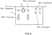
- the driving mechanism 5 provided to the bed base 4 comprises a robot arm 6 and a plurality of driving force input ports (rotated drivers) 7 to which a distal end portion of this robot arm is selectively connected.
- the plurality of driving force input ports 7 (7A, 7B, 7C, 7D, 7E) correspond to moving motions in the bed portion 3 different from each other, respectively.
- the mobile body 13B is normally arranged so that the movable bed surface 2B is positioned at the same level as the fixed bed surface 2A.
- the movable bed surface 2B and the fixed bed surface 2A are positioned at the same level, configuring the bed surface 2 in a common plane.
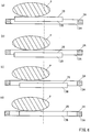
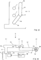
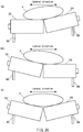
- the mobile body 13B is lowered from the state in FIG. 5(a) to the state in FIG. 5(b) by the driving mechanism 5. At this time, since the body of the care receiver P is supported by the fixed bed surface 2A of the fixed member 13A, it is held at the level of the fixed bed surface 2A.
- the mobile body 13B is moved to one side in the lateral direction by the driving mechanism 5, utilizing a lateral interval between the fixed member 13A and the mobile body 13B. At this time, since the mobile body 13B is away from the body of the care receiver P, it can be moved smoothly without causing discomfort for the care receiver P.
- the mobile body 13B is elevated as illustrated in FIG. 5(d) by the driving mechanism 5.
- the body of the care receiver P is pressed up by the movable bed surface 2B of the mobile body 13B and elevated away from the fixed bed surface 2A.
- the mobile body 13B is moved to another side in the lateral direction by the driving mechanism 5, utilizing a lateral interval between the fixed member 13A and the mobile body 13B. Thereby, the body of the care receiver P is also moved together with the mobile body 13B. At this time, since the body of the care receiver P is away from the fixed bed surface 2A, it can be moved smoothly without causing discomfort for the care receiver P.
- the mobile body 13B is lowered to a position lower than the fixed bed surface 2A as illustrated in FIG. 6(b) by the driving mechanism 5. Thereby, the body of the care receiver P is placed on the fixed bed surface 2A.
- the mobile body 13B is moved to one side in the lateral direction by the driving mechanism 5. At this time, since the mobile body 13B is away from the body of the care receiver P, it can be moved smoothly without causing discomfort for the care receiver P.
- the mobile body 13B is elevated up to the level of the fixed bed surface 2A by the driving mechanism 5.
- the movable bed surface 2B of the mobile body (movable member) 13B and the fixed bed surface 2A of the fixed member 13A become flush with each other, and the both form the bed surface 2 in a common plane.
- the body of the care receiver P can be moved little by little locally (for example, only shoulder portion, or only waist portion) to the left (or to the right).
- the above-mentioned posture changing motion can be performed in the shoulder region 9 and the waist region 10 independently from each other. For example, first the shoulder portion of the care receiver P can be moved in the shoulder region 9, and after that, the waist portion of the care receiver P can be moved in the waist region 10.
- the body of the care receiver P can be moved little by little locally (for example, only shoulder portion, or only waist portion) so as to change his/her posture into the optimal one without difficulty.
- the nursing bed 1 of this embodiment there is an interval between the fixed member 13A and the mobile body (movable member) 13B in the horizontal direction and nothing is filled in this interval, and therefore a large moving stroke of the mobile body 13B in the horizontal direction can be secured, and also a filler in the interval would never protrudes upward accompanying the horizontal movement of the mobile body 13B.
- a plurality of mobile bodies 13B belonging to the shoulder region 9 may be moved simultaneously or the plurality of mobile bodies 13B belonging to the shoulder region 9 may be driven individually. Additionally, the plurality of mobile bodies 13B belonging to the shoulder region 9 may be divided into several groups so as to drive the plurality of mobile bodies 13B belonging to each group simultaneously. The same applies to a plurality of mobile bodies 13B belonging to the waist region 10.
- FIG. 7 illustrates a variation of the embodiment in FIG. 1 .
- the fixed member 13A configuring a part of the bed portion 3 is formed in a lattice shape by a plurality of slender members extending in the longitudinal direction and the lateral direction.
- a plurality of mobile bodies (movable members) 13B configuring another part of the bed portion 3 are movably arranged in each opening of the lattice-shaped fixed member 13A.
- the body of the care receiver P can be moved little by little locally so as to change his/her posture into the optimal one without difficulty.
- a plurality of mobile bodies 13B belonging to the shoulder region 9 may be driven simultaneously so as to make them perform the rotational motion or they may be driven individually so as to make them perform the rotational motion.
- the plurality of mobile bodies 13B belonging to the shoulder region 9 may be divided into several groups so as to drive the plurality of mobile bodies 13B belonging to each group simultaneously and make them perform the rotational motion. The same applies to a plurality of mobile bodies 13B belonging to the waist region 10.
- FIG. 8 illustrates another variation of the embodiment in FIG. 1 .
- the whole bed portion 3 of the nursing bed 1 is configured by a slit-shaped fixed member 13A and a plurality of slender mobile bodies (movable members) 13B.
- the plurality of mobile bodies 13B are divided into several groups and the plurality of mobile bodies 13B belonging to each group are driven simultaneously so as to make them perform the rotational motion.
- the plurality of mobile bodies 13B may be individually driven respectively so as to make them perform the rotational motion.
- the whole body of the care receiver P can be moved by the mobile bodies 13B little by little locally so as to change his/her posture into the optimal one without difficulty.
- FIG. 9 illustrates another variation of the embodiment in FIG. 1 .
- the whole bed portion 3 of the nursing bed 1 is configured by a lattice-shaped fixed member 13A and a plurality of mobile bodies (movable members) 13B.
- the plurality of mobile bodies 13B are divided into several groups and the plurality of mobile bodies 13B belonging to each group are driven simultaneously so as to make them perform the rotational motion.
- the plurality of mobile bodies 13B may be individually driven respectively so as to make them perform the rotational motion.
- the whole body of the care receiver P can be moved by the mobile bodies 13B little by little locally so as to change his/her posture into the optimal one without difficulty.
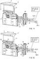
- the driving mechanism 5 comprises a support base portion 15 whose upper end is provided with (a part of) the bed portion 3.
- the bed portion 3 composed of a plurality of mobile bodies (movable members) 13B is schematically illustrated as an integrated object.
- a lower end portion of the support base portion 15 is supported by a linear motion support member (linear guide) 16.
- the linear motion support member 16 supporting the support base portion 15 is provided to an upper end of a movable support plate 17.
- the movable support plate 17 is supported so as to be moved vertically by a pair of linear motion support members (linear guide) 18 which are extendedly arranged in the vertical direction.
- a rack 19 is extendedly arranged in the vertical direction on one side end portion of the movable support plate 17, and a pinion 20 is engaged with the rack 19.
- This pinion 20 is provided to one end of a connection shaft 21, and a wheel of a worm gear 22 is provided to the other end of the connection shaft 21.
- This wheel of the worm gear 22 is engaged with a worm of the worm gear 22, and this worm is formed in an input shaft 23 whose distal end portion forms a driving force input port 7.
- This driving force input port 7 is an input portion of rotational power for vertically moving the bed portion 3.
- a rack 24 is provided to a lower end portion of the support base portion 15, and a pinion 25 is engaged with this rack 24.
- This pinion 25 is provided to an upper end of a connection shaft 26, and a bevel gear 27 is provided to a lower end of the connection shaft 26.
- This bevel gear 27 is engaged with a bevel gear 28 which is rotatably provided to the movable support plate 17.
- a pulley 29 is integrally formed in the bevel gear 28 provided to the movable support plate 17, and a belt 30 is wound on this pulley 29.
- This belt 30 is wound on another pulley 31 which is provided to one end of a connection shaft 32, and a wheel of a worm gear 33 is provided to the other end of the connection shaft 32. The wheel of the worm gear 33 is engaged with the worm of the worm gear 33.
- a pinion 35 is provided to an end portion of a connection shaft 34 where the worm of the worm gear 33 is formed, and this pinion 35 is engaged with a rack 36 extendedly arranged in the vertical direction.
- This rack 36 is supported so as to be moved vertically by a linear motion support member (linear guide) 37 extendedly arranged in the vertical direction.
- Another rack 38 is supported by this linear motion support member 37 integrally with the rack 36 so as to be moved vertically, and this rack 38 is engaged with a pinion 39.
- This pinion 39 is provided to one end of an input shaft 40, and the other end of this input shaft 40 forms the driving force input port 7.
- This driving force input port 7 is an input portion of rotational power for horizontally moving the bed portion 3 in the lateral direction.
- connection shaft 34 is vertically moved integrally with the movable support plate 17, the rack 36 is also moved vertically at the same time. At this time, a driving force input port 7C for lateral movement is rotated, which causes no problem since this driving force input port 7C for lateral movement is free.
- the worm gear 22 has a structure which cannot be rotated from the output side, even when an applied torque of the driving force input port 7B for vertical movement is removed, its posture at the time can be kept.
- the worm gear 33 since the worm gear 33 has a structure which cannot be rotated from the output side, even when an applied torque of the driving force input port 7C for lateral movement is removed, its posture at the time can be kept.
- FIG. 13 illustrates a driving mechanism for the leg portion for pressing up the movable rectangular piece 14 configuring the leg region 11 from below.
- this driving mechanism for the leg portion when a driving force input port 7A (7) for the leg portion is rotated, an input shaft 41 where this driving force input port 7A is formed in a distal end portion thereof is rotated.
- a worm configuring a worm gear 42 is formed in this input shaft 41 so that power is transmitted to a wheel also configuring the worm gear 42.
- the wheel of the worm gear 42 is provided to one end of a connection shaft 43, and a pinion 44 is provided to the other end of this connection shaft 43.
- the pinion 44 is engaged with a rack 45 which is provided to a side end portion of the movable support plate 17.
- the movable support plate 17 is supported so as to be moved vertically by a pair of linear motion support members (linear guide) 46 extendedly arranged in the vertical direction.
- the rack 45 is moved vertically by a rotation of the pinion 44, and thereby the movable support plate 17 is moved vertically.
- a lower end portion of a pressing-up member 47 is fixed to an upper end portion of the movable support plate 17, and the movable rectangular piece 14 is pressed up from below the same by an upper end portion of this pressing-up member 47.
- the robot arm 6 has a proximal end portion 6a and a distal end portion 6b, and the proximal end portion 6a of the robot arm 6 is mounted to an upper end portion of a robot main shaft 51.
- a rotational driver 52 is rotatably provided to the distal end portion 6b of the robot arm 6.
- the robot arm 6 has a proximal end side link member 53 and a distal end side link member 54.
- a proximal end portion of the proximal end side link member 53 configures the proximal end portion 6a of the robot arm, and a distal end portion of the distal end side link member 54 configures the distal end portion 6b of the robot arm 6.
- a distal end portion of the proximal end side link member 53 and a proximal end portion of the distal end side link member 54 are rotatably connected with each other.
- a driving motor 55 for the robot main shaft 51 is provided inside the bed base 4, and the robot main shaft 51 is rotationally driven about a first axis L1 by this driving motor 55.
- a driving motor 56 for the distal end side link member 53 is provided inside the proximal end side link member 53, and the distal end side link member 54 is rotationally driven about a second axis L2 by this driving motor 56.
- a driving motor 57 for the rotational driver 52 is provided inside the distal end side link member 54, and the rotational driver 52 is rotationally driven about a third axis L3 by this driving motor 57.
- first axis L1, the second axis L2, and the third axis L3 are parallel to one another.
- Rotations of the respective driving motors 55, 56, and 57 are controlled by a robot control portion 58.
- the robot control portion 58 can store a program particular to a care receiver P so as to realize a bedsore-prevention motion particular to said care receiver P.
- a bevel gear 59 on the driving motor 57 side and a bevel gear 60 on the rotational driver 52 side are engaged with each other.
- a through hole 61 including a spline groove is formed at the center of the bevel gear 60 on the rotational driver 52 side, and a rotational driving shaft 62 is inserted through this through hole 61 so as to be moved along the third axis L3.
- This rotational driving shaft 62 is spline-fitted to the through hole of the bevel gear 60. Thereby, the rotational driving shaft 62 is prevented from rotating about the third axis L3 with respect to the bevel gear 60 and allowed to be linearly moved along the third axis L3.
- the rotational driver 52 is mounted to one end portion of the rotational driving shaft 62, and a distal end portion of a piston 64 of an air cylinder 63 is connected to the other end portion of the rotational driving shaft 62 via a bearing 65.
- the rotational driver 52 moves forward together with the rotational driving shaft 62 along the third axis L3.
- connection mechanism for connecting the driving force input port 7 on the bed base 4 side and the rotational driver 52 on the robot arm 6 side will be described with reference to FIG. 18 to FIG. 20 .
- an oldham coupling is employed as illustrated in FIG. 18 and FIG. 19 so as to absorb this deviation.
- projections of its hubs 66, 67 slide on grooves of a slider 68 so as to absorb the deviation (refer to FIG. 20 ).
- the hub 66 and the slider 68 configure the rotational driver 52, and the hub 67 configures the driving force input port 7.
- the slider 68 is mounted to the hub 66 on the robot arm 6 side to be free in the horizontal direction for attaching/detaching between a driving side and a driven side, and a spring 69 is interposed between the hub 66 on the robot arm 6 side and the slider 68 for mitigating impact in the axis direction upon coupling.
- the robot arm 6 is driven, thereby bringing and positioning the rotational driver 52 on the distal end of the arm close to a desired driving force input port 7 so as to face the same.
- the air cylinder 63 on the distal end of the robot arm 6 is driven, thereby advancing the rotational driver 52 toward the driving force input port 7 along the third axis L3 so that the both are engaged with each other.
- a stroke length of the air cylinder 63 is detected so as to confirm that the rotational driver 52 and the driving force input port 7 are normally engaged with each other.
- the driving motor 57 on the distal end of the robot arm 6 is driven so as to rotate the rotational driver 52. Since the rotational driver 52 is connected to the driving force input port 7, the rotational force from the rotational driver 52 is transmitted to the driving force input port 7. As a result, a part of the bed portion 3 corresponding to this driving force input port 7 performs a predetermined motion.
- the driving motor 57 After rotating the driving force input port 7 by a predetermined amount, the driving motor 57 is stopped.
- the air cylinder 63 is driven so as to bring back the rotational driver 52, thereby separating the rotational driver 52 from the driving force input port 7.
- the robot arm 6 is driven so as to move and position the rotational driver 52 to the next driving force input port 7.
- the rotational driver 52 on the distal end of the robot arm 6 is connected to the first driving force input port 7A (corresponding to the right knee) and the driving motor 57 is rotated. Thereby, the rotational driving force from the rotational driver 52 is transmitted to a driving system of a part corresponding to the right knee of the bed portion 3 of the nursing bed 1. As a result, the part corresponding to the right knee is deformed into a mountain shape.
- the air cylinder 63 is driven so as to separate the power connection portions (the rotational driver 52 and the driving force input port 7), and the robot arm 6 is driven so as to connect the rotational driver 52 on the distal end of the robot arm 6 to the second driving force input port 7B (corresponding to vertical motions of the waist region).
- the driving motor 57 is rotated.
- the rotational driving force from the rotational driver 52 is transmitted to a vertical driving system of the mobile bodies 13B corresponding to the waist region 10 of the bed portion 3 of the nursing bed 1.
- the mobile bodies 13B corresponding to the waist region 10 are elevated.
- the air cylinder 63 is driven so as to separate the power connection portions, and the robot arm 6 is driven so as to connect the rotational driver 52 on the distal end of the robot arm 6 to the third driving force input port 7C (corresponding to horizontal motions of the waist region).
- the driving motor 57 is rotated.
- the rotational driving force from the rotational driver 52 is transmitted to a horizontal driving system of the mobile bodies 13B corresponding to the waist region 10 of the bed portion 3 of the nursing bed 1.
- the mobile bodies 13B corresponding to the waist region 10 are moved horizontally.
- the air cylinder 63 is driven so as to separate the power connection portions, and the robot arm 6 is driven so as to connect the rotational driver 52 on the distal end of the robot arm 6 to the fourth driving force input port 7D (corresponding to vertical motions of the shoulder region).
- the driving motor 57 is rotated.
- the rotational driving force from the rotational driver 52 is transmitted to a vertical driving system of the mobile bodies 13B corresponding to the shoulder region 9 of the bed portion 3 of the nursing bed 1.
- the mobile bodies 13B corresponding to the shoulder region 9 are elevated.
- the air cylinder 63 is driven so as to separate the power connection portions, and the robot arm 6 is driven so as to connect the rotational driver 52 on the distal end of the robot arm 6 to the fifth driving force input port 7E (corresponding to horizontal motions of the shoulder region).
- the driving motor 57 is rotated.
- the rotational driving force from the rotational driver 52 is transmitted to a horizontal driving system of the mobile bodies 13B corresponding to the shoulder region 9 of the bed portion 3 of the nursing bed 1.
- the mobile bodies 13B corresponding to the shoulder region 9 are moved horizontally.
- the air cylinder 63 is driven so as to separate the power connection portions, and the robot arm 6 is driven so as to connect the rotational driver 52 on the distal end of the robot arm 6 to the third driving force input port 7C (corresponding to horizontal motions of the waist region).
- the driving motor 57 is rotated.
- the rotational driving force from the rotational driver 52 is transmitted to the horizontal driving system of the mobile bodies 13B corresponding to the waist region 10 of the bed portion 3 of the nursing bed 1.
- the mobile bodies 13B corresponding to the waist region 10 are further moved horizontally.
- the air cylinder 63 is driven so as to separate the power connection portions, and the robot arm 6 is driven so as to connect the rotational driver 52 on the distal end of the robot arm 6 to the fifth driving force input port 7E (corresponding to horizontal motions of the shoulder region).
- the driving motor 57 is rotated.
- the rotational driving force from the rotational driver 52 is transmitted to the horizontal driving system of the mobile bodies 13B corresponding to the shoulder region 9 of the bed portion 3 of the nursing bed 1.
- the mobile bodies 13B corresponding to the shoulder region 9 are further moved horizontally.
- a robot is taught as mentioned above so as to program a bedsore prevention motion suitable for a care receiver P.
- the above-mentioned motion example is of the case when the trunk in the shoulder portion and the waist portion is shifted to the left. Further, for shifting the trunk to the right hereafter, the above-mentioned procedure is performed inversely where the trunk is once returned straight, and further the driving force input port corresponding to the left knee is selected so as to change the posture.
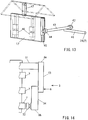
- the robot arm 6 may be configured by a single link member including a proximal end portion 6a and a distal end portion 6b. Namely, as illustrated in FIG. 21 and FIG 22 , a base end portion of a single link member 49 is mounted to the upper end portion of the robot main shaft 51 and the rotational driver 52 is provided to the distal end portion of said link member 49.
- the plurality of driving force input ports 7 are arranged on a virtual circle about the rotational axis (the first axis L1) of the robot main shaft 51.
- the robot arm 6 is turned by the rotation of the robot main shaft 51 so that the rotational driver 52 on the distal end portion of the robot arm 6 can be positioned in front of a desired driving force input port 7.
- connection mechanism of the rotational driver 52 and the driving force input port 7 is the same as that of the embodiment above.
- a cross-shaped connecting recessed portion 7a is formed in the driving force input port 7, and also a cross-shaped connecting protruding portion 52a is formed in the rotational driver 52.
- the connecting recessed portion 7a and the connecting protruding portion 52a respectively have a dimension and a shape to be gently fitted to each other.
- the connecting protruding portion 52a has a tapered shape, while the connecting recessed portion 7a has an inclined shape corresponding to the tapered shape of the connecting protruding portion 52a.
- the connecting protruding portion 52a of the rotational driver 52 is fitted to the connecting recessed portion 7a formed in the driving force input port 7 from the front.
- a positioning function is exerted in a direction that a positioning error of the rotational driver 52 to the driving force input port 7 or the like is absorbed, thereby achieving a natural engagement.
- connection may be configured so that the both are brought close to each other and connected along a direction orthogonal to the rotational axis(the third axis L3).
- the connecting recessed portion 7a is formed in the driving force input port 7 along its diameter direction, and also the connecting protruding portion 52a is formed in the rotational driver 52 along its diameter direction.
- the connecting recessed portion 7a and the connecting protruding portion 52a respectively have a dimension and a shape to be gently fitted to each other.
- the connecting protruding portion 52a of the rotational driver 52 can be fitted to the connecting recessed portion 7a formed in the driving force input port 7 from its side. Therefore, in connection to the driving force input port 7, the rotational driver 52 does not need to be advanced in the rotational axis (the third axis L3) direction, and therefore the air cylinder 63 or the like can be omitted so that the structure is simplified.
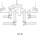
- a plurality of driving force input ports 7 of two nursing beds 1 may be selectively driven by the rotational driver 52 of the common robot arm 6.
- each of bed portion 3 of the nursing bed 1 and its driving mechanism (except for the robot arm part) are arranged.
- the robot main shaft 51 is arranged in the vertical direction, and each driving force input port 7 is also arranged in the vertical direction via the bevel gear 70.
- a plurality of driving force input ports 7 of one nursing bed 1 and a plurality of driving force input ports 7 of the other nursing bed 1 can be rotationally driven selectively by the rotational driver 52 of the common robot arm 6.
- a mechanism for moving the robot main shaft 51 along its rotational axis may be provided instead of the mechanism that the air cylinder is provided to the arm distal end, so as to move the whole robot arm 6 by advance/retreat motion of the robot main shaft 51.
- a connecting mechanism of the rotational driver 52 and the driving force input port 7 may be configured so that the air cylinder or the like is provided on the driving force input port 7 side so as to drive the driving force input port 7 forward and backward to the rotational driver 52, instead of the method that the rotational driver 52 is driven forward and backward to the driving force input port 7.
- a friction plate may be provided to the rotational driver 52 on the distal end of the robot arm 6 and also a friction plate may be provided to the driving force input port 7 as well, instead of the method that the recessed portion and the protruding portion are fitted to each other as mentioned above.
- a method to connect the rotational driver 52 and the driving force input port 7 by magnetic force may be employed.
- the driving motor 57 is installed on the distal end of the robot arm 6 so as to supply its rotational driving force to each driving force input port 7.
- a plurality of driving motors may be installed on the bed base 4 side for each part of the bed portion 3 and a clutch switching when transmitting the driving force to each part may be operated by the robot arm 6.
- a switch for operating the clutch is installed on the bed base 4 side instead of the driving force input port 7.
- a single driving motor may be installed on the bed base 4 side and the clutch switching when distributing/transmitting its driving force to each part may be operated by the robot arm 6.
- a switch for operating the clutch is installed on the bed base 4 side instead of the driving force input port 7.
- the driving method may be air driving (such as air bag, air cylinder) instead of the motor rotation, regardless of whether the driving source is on either the robot side or the bed base 4 side, or regardless of either a single or a plurality of driving source/sources is/are installed.
- air driving such as air bag, air cylinder
- the robot as a switching mechanism of driving force may be mounted on a mobile carriage without installing the same on the bed base 4 side.
- the switching mechanism of driving force may be configured so as to switch by a sequencer, for example without using the robot.
- the mobile bodies (movable members) 13B may be driven to move also in the longitudinal direction in addition to the vertical direction and the lateral direction, and the mobile bodies 13B are made to move rotationally in each of the lateral direction and the longitudinal direction.
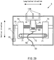
- FIG. 26 to FIG. 29 illustrate the driving mechanism 5 which enables driving of the mobile bodies 13B in three directions of vertical, lateral, and longitudinal directions. This driving mechanism 5 drives the integrally-formed three mobile bodies 13B simultaneously, as illustrated in FIG. 26 .
- the driving mechanism 5 illustrated in FIG. 27 to FIG. 29 has a pair of first ball screws 71 extending in the lateral direction, and the pair of ball screws 71 are configured to be rotationally moved simultaneously via a first toothed belt 72.
- One of the pair of first ball screws 71 forms a first inner port 73 at its one end, and the first inner port 73 is connected to one of the driving force input ports 7 via a flexible wire (not illustrated).
- a pair of first nut members 74 are screwed and fastened to the pair of first ball screws 71, and the pair of first nut members 74 are moved in the lateral direction along a guide rail (not illustrated) by a rotation of the pair of first ball screws 71.
- a second ball screw 75 extending in the longitudinal direction is rotatably inserted through the pair of first nut members 74.
- the center part of the second ball screw 75 is threaded, and a second nut member 76 is screwed and fastened to this threaded part.
- a second toothed belt 77 is engaged with the second ball screw 75, and the second toothed belt 77 is travelably supported by four rotational members 78.
- the second toothed belt 77 may be pressed from above by a roller or the like, for example.
- One of the four rotational members 78 supporting the second toothed belt 77 forms a second inner port 79, and the second inner port 79 is connected to one of the driving force input ports 7 via a flexible wire (not illustrated).
- the second toothed belt 77 travels, the second ball screw 75 is rotated, and accordingly the second nut member 76 is moved in the longitudinal direction along a guide rail (not illustrated).
- a third ball screw 80 extending in the vertical direction is rotatably supported to the second nut member 76, and the third ball screw 80 is screwed to a third nut member 81 connected to the mobile body 13B.
- a lower end portion of the third ball screw 80 is connected to the third inner port 83 via a flexible wire 82.
- the third inner port 83 is connected to one of the driving force input ports 7 via a flexible wire (not illustrated).
- the mobile body 13B can perform a rotational motion about a lateral axis, namely a moving motion of a patient in the height direction, in addition to the rotational motion about a longitudinal axis, namely the moving motion of the trunk of the patient in the lateral direction ( FIG. 5 , FIG. 6 ).
- the second nut member 76 is moved in the lateral direction when the first inner port 73 is rotated, but at this time, if the second toothed belt 77 is stopped, the second ball screw 75 is rotationally driven and the second nut member 76 is moved also in the longitudinal direction simultaneously.
- the second inner port 79 is rotated simultaneously so as to cancel the derived movement.
- the robot arm 6 of the second robot is used to rotationally drive the driving force input port 7 connected to the second inner port 79.
- the mobile body 13B can be moved exactly to a predetermined position in each of the vertical, lateral, and longitudinal directions.
- the driving mechanism 5 illustrated in FIG. 30 is configured to drive each of a plurality of mobile bodies 13B separately.
- one mobile body 13B is assigned to one third ball screw 80.
- the individual mobile body 13B can be driven in the vertical, lateral, and longitudinal directions, independently.
- the robot arm 6 is driven by a program previously installed in the robot control portion 58 so as to automatically perform a predetermined bedsore prevention motion, and therefore a caregiver does not need to work periodically in midnight or the like, relieving mental and physical burden on the caregiver and also relieving mental burden on the care receiver P to the caregiver.
- the rotational driving force is selectively transmitted to a plurality of driving force input ports 7 by the common rotational driver 52, and thereby a plurality of different motions can be realized by a single drive source, simplifying the configuration.
- a specifying order (sequence) of a supply point of driving force (driving force input port 7) can be easily changed. Therefore, flexibility for realizing a plurality of different motions can be enhanced.
- the mobile body (movable member) 13B performs rotational motion in a range where the fixed member 13A exists in every direction of the vertical, lateral, and longitudinal directions
- the mobile body 13B can be moved in the longitudinal direction in addition to the lateral direction of the bed, and also the mobile body 13B does not protrude in that direction and delicate motions become possible.
- the upper body is moved to the fore side and the lower body is moved to the rear side, a motion for stretching the upper and lower bodies becomes possible.
- FIG. 31 to FIG. 35 Next, a nursing bed according to another embodiment of the present invention will be described referring to FIG. 31 to FIG. 35 .
- the bed portion 3 comprises a plurality of bed portion units 3A, as illustrated in FIG. 31 and FIG. 32 .
- the driving mechanism 5 illustrated in FIG. 27 to FIG. 29 is stored inside each bed portion unit 3A.
- Each bed portion unit 3A has a slit-shaped fixed member 13A and a plurality of slender mobile bodies (movable members) 13B, as illustrated in FIG. 33 .
- the driving force input ports 7 and the inner ports 73, 79, and 83 are connected by flexible wires 85, and power is supplied to the driving mechanism 5 in the bed portion unit 3A via the flexible wires 85.
- a plurality of bed portion units 3A are driven to be inclined independently to each other by bed portion unit driving unit 86.
- the bed portion unit driving unit 86 are connected to the driving force input ports 7 via flexible wires (not illustrated), and power is supplied therefrom.
- the elevating/lowering driving mechanism illustrated in FIG. 13 for example may be employed.
- the mobile bodies 13B can be driven in different motions for each bed portion unit 3A.
- a plurality of mobile bodies 13B belonging to the same bed portion unit 3A may be integrally formed and driven simultaneously or they may be formed separately and driven individually.
- a plurality of mobile bodies 13B belonging to the same bed portion unit 3A may be divided into several groups and the plurality of mobile bodies 13B belonging to each group may be driven simultaneously.
- the driving mechanism 5 can make the mobile body 13B perform the rotational motion illustrated in FIG. 5 and FIG. 6 .
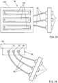
- each bed portion unit 3A may be configured by a lattice-shaped fixed member 13A and a plurality of mobile bodies (movable members) 13B, as illustrated in FIG. 36 and FIG. 37 .
- the mobile bodies 13B can be driven in different motions for each bed portion unit 3A.
- a plurality of mobile bodies 13B belonging to the same bed portion unit 3A may be integrally formed and driven simultaneously or they may be formed separately and driven individually.
- a plurality of mobile bodies 13B belonging to the same bed portion unit 3A may be divided into several groups and the plurality of mobile bodies 13B belonging to each group may be driven simultaneously.
- FIG. 38 and FIG. 39 Next, a nursing bed according to another embodiment of this invention will be described referring to FIG. 38 and FIG. 39 .
- the nursing bed according to this embodiment is configured as a module type such that the bed portion unit 3A and the driving mechanism 5 can be detachably mounted to a desired position of the whole bed portion.
- the driving mechanism 5 is modularized into separable units 5A, 5B so as to be detachable, as illustrated in FIG. 38 .
- the unit 5B as a part of the driving mechanism 5 can be removed as illustrated in FIG. 39 .
- a single robot is shared by a plurality of modules 5A, 5B.
- the structure can be simplified and manufacturing cost can be reduced.
- the nursing bed according to this embodiment is configured as a module type such that the bed portion unit 3A and the driving mechanism 5 can be detachably mounted to a desired position of the whole bed portion, a module can be properly added to a part where especially bedsores need to be prevented according to types of the care receivers P (severely ill in legs, severely ill in the waist, or the like). Thereby, various types of care receivers P can be flexibly cared.
- FIG. 40 to FIG. 42 Next, a nursing bed according to another embodiment of this invention will be described referring to FIG. 40 to FIG. 42 .
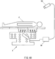
- the nursing bed comprises, in above-mentioned each embodiment and its variation, a posture information acquisition unit 90 to acquire a posture information about a posture of the care receiver P lying on the bed and a control unit 58 to control the driving mechanism (movable member driving unit) 5 based on the posture information acquired by the posture information acquisition unit 90 so as to change the posture of the care receiver P into a predetermined posture by motions of the mobile bodies (movable members) 13B.
- the control unit 58 analyzes a current posture information acquired by the posture information acquisition unit 90 and a posture information of a target predetermined posture, and makes the mobile bodies 13B move multiple times so that the difference between the current posture and the predetermined posture of the care receiver P becomes smaller.
- the posture information acquisition unit 90 is preferably an infrared camera for acquiring a posture information by imaging the care receiver P.
- the infrared camera By using the infrared camera, even when the care receiver P is covered with bedclothes, the posture and position of a human body can be specified by an image process for extracting only the limbs of the human body.
- a plurality of easy postures for the care receiver P or postures instructed by a physician are previously registered so that the current posture can approach one certain easy posture little by little.
- one easy posture can be shifted to another easy posture gradually.
- a plurality of mobile bodies 13B are rotationally moved in order little by little so that the posture of the care receiver P can be a certain (easy) posture, enabling a natural body position movement for the care receiver P.
- FIG. 41 illustrates an operation procedure of the nursing bed according to this embodiment.
- a certain target posture is set (S1)
- the care receiver P is imaged by the camera 90 (S2) so as to specify the posture of the care receiver P (S3).
- the difference between the current posture and the target posture of the care receiver P is analyzed, and the difference in each portion (shoulder portion, waist portion, or the like) of the care receiver is obtained (S4).
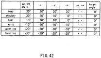
- FIG. 42 illustrates an example of a pattern of changing from the current angle to the target angle when moving the mobile bodies (movable member) 13B.
- a rotational angle about the longitudinal axis direction of the bed is assumed.
- respective portions are moved by a predetermined amount one by one.
- a plurality of portions may be moved simultaneously. Note that, however, a plurality of robot arms 6 are needed in that case.
- a predetermined amount moved at a time may be different between respective portions.
- the shape of the bed is formed in a certain posture and a posture of the care receiver P follows and fits to the shape of the bed.
- a gap is often present between the shape of the bed and the posture of the care receiver P, and therefore there are restrictions to bring the care receiver P into a desirable posture.
- the care receiver P is imaged by the camera 90 so as to specify the posture, and the posture of the care receiver P is proactively brought into a desired posture based on the specified posture. Thereby, the posture of the care receiver P can be exactly changed into a desired posture.
Landscapes
- Health & Medical Sciences (AREA)
- Nursing (AREA)
- General Health & Medical Sciences (AREA)
- Life Sciences & Earth Sciences (AREA)
- Animal Behavior & Ethology (AREA)
- Public Health (AREA)
- Veterinary Medicine (AREA)
- Engineering & Computer Science (AREA)
- Rehabilitation Therapy (AREA)
- Robotics (AREA)
- Mechanical Engineering (AREA)
- Invalid Beds And Related Equipment (AREA)
Abstract
Description
- The present invention relates to a nursing bed and particularly relates to a nursing bed capable of moving the body of a care receiver lying on the bed.
- Care receivers get bedsores easily if they need to be in bed for a long period of time, which is severely painful for them. Bedsores occur especially in protruding parts with bones such as the waist, shoulders, and ankles because of poor blood circulation due to pressure of the body weight, resulting in necrosis.
- Posture of a care receiver needs to be changed appropriately in order to prevent bedsores, and in particular when the care receiver has difficulty moving his/her body by himself/herself, a caregiver needs to take appropriate measures such as putting a pillow under the waist of the care receiver.
- The caregiver needs to move a heavy body of the care receiver in order to prevent bedsores, which is a hard work. Moreover, the work needs to be done night and day, for example every one or two hours, which is a heavy burden for the caregiver. Additionally, the care receiver also tends to feel a mental burden about forcing a hard work on the caregiver.
- In order to reduce such burden on the caregiver (and the care receiver), a technology is proposed, where a part of a bed surface (lying surface) of a nursing bed is made movable and the movable portion of the bed surface is appropriately moved manually or by using power so as to change the posture of the case receiver (refer to
Patent Literatures 1 to 11 below). -
- [Patent Literature 1]
Japanese Patent No. 2716093 - [Patent Literature 2]
Japanese Patent Application Laid-open No. 2000-342633 - [Patent Literature 3]
Japanese Patent Application Laid-open No. 2002-78755 - [Patent Literature 4]
Japanese Patent Application Laid-open No. 4231363 - [Patent Literature 5]
Japanese Patent Application Laid-open No. H01-238859 - [Patent Literature 6]
Japanese Patent Application Laid-open No. H07-8523 - [Patent Literature 7]
Japanese Patent Application Laid-open No. H07-303674 - [Patent Literature 8]
Japanese Patent Application Laid-open No. H11-239524 - [Patent Literature 9]
Japanese Patent Application Laid-open No. 2000-325408 - [Patent Literature 10]
Japanese Patent Application Laid-open No. 2002-85481 - [Patent Literature 11]
Japanese Patent Application Laid-open No. 2004-222908 - However, in a conventionally proposed nursing bed, the whole body of a care receiver is merely slid simultaneously on a bed portion of a bed, or a part (for example, a part corresponding to the upper body) of the bed surface of the bed is merely inclined so as to support the posture of the care receiver on the inclined bed surface of the bed, or alternatively, an unnatural strong force is applied locally when moving the body of the care receiver, imposing a burden on the body of the care receiver.
- Therefore, in a conventionally proposed nursing bed, it is excessively difficult or impossible to change the posture of a care receiver into his/her optimal position for preventing bedsores or the like without difficulty.
- Additionally, in a conventional nursing bed, since a mechanism for changing the posture of a care receiver is mechanically incorporated integrally with a bed body, a posture changing mechanism cannot be appropriately added to especially a portion where bedsores need to be prevented according to types of care receivers (severely ill in legs, severely ill in the waist, or the like).
- The present invention is made considering the above-mentioned problems of the conventional technology and its object is to provide a nursing bed capable of changing the posture of a care receiver lying on the bed into his/her optimal position without difficulty.
- The present invention according to a first aspect is a nursing bed with a dimension in a longitudinal direction and a dimension in a lateral direction, comprising: a fixed member forming a fixed bed surface of a bed portion on which a care receiver lies; a movable member which can be moved relative to the fixed member and forms a movable bed surface of the bed portion; and a movable member driving unit for driving the movable member, wherein the fixed member has a plurality of slender parts each extending in the lateral direction or the longitudinal direction, and wherein the movable member has a mobile body which can be protruded upward relative to the fixed bed surface and also moved in at least one of the longitudinal direction and the lateral direction via an interval between the plurality of slender parts by the movable member driving unit.
- The present invention according to a second aspect is that, in the present invention according to the first aspect, the fixed member further has a plurality of additional slender parts each extending in the longitudinal direction or the lateral direction, wherein the fixed member is formed in a lattice shape by the plurality of slender parts and the plurality of additional slender parts.
- The present invention according to a third aspect is that, in the present invention according to the first or second aspect, the movable member has the plurality of mobile bodies, wherein the movable member driving unit can make the plurality of mobile bodies move simultaneously.
- The present invention according to a fourth aspect is that, in the present invention according to any one of the first to third aspects, the movable member has the plurality of mobile bodies, wherein the movable member driving unit can make the plurality of mobile bodies move independently from each other.
- The present invention according to a fifth aspect is that, in the present invention according to any one of the first to fourth aspects, the movable member driving unit is configured such that a rotational driving force is transmitted from a rotational driver mounted to a distal end portion of a robot arm.
- The present invention according to a sixth aspect is that, in the present invention according to the fifth aspect, the movable member driving unit has a plurality of rotated drivers selectively and separably connected to the rotational driver, and the plurality of rotated drivers are installed corresponding to motions of the movable members different from each other, respectively.
- The present invention according to a seventh aspect is that, in the present invention according to any one of the first to sixth aspects, the movable member is arranged such that the movable bed surface is normally positioned at the same level as the fixed bed surface or at a level lower than the fixed bed surface.
- The present invention according to an eighth aspect is a nursing bed with a dimension in a longitudinal direction and a dimension in a lateral direction, comprising: a bed portion on which a care receiver lies, having a plurality of bed portion units which can be moved so as to be inclined independently from each other; and a bed portion unit driving unit for driving the plurality of bed portion units so as to be inclined independently from each other, wherein each of the plurality of bed portion units has a fixed member forming a fixed bed surface of the bed portion unit; a movable member which can be moved relative to the fixed member and forms a movable bed surface of the bed portion unit; and a movable member driving unit for driving the movable member, and wherein the movable member has a mobile body which can be protruded upward relative to the fixed bed surface and also moved in at least one of the longitudinal direction and the lateral direction via an opening formed in the fixed member by the movable member driving unit.
- The present invention according to a ninth aspect is that, in the present invention according to the eighth aspect, in at least one bed portion unit of the plurality of bed portion units, the movable member driving unit can make the mobile body rotationally move about an axis in the longitudinal direction or an axis in the lateral direction.
- The present invention according to a tenth aspect is that, in the present invention according to the eighth or ninth aspect, at least one bed portion unit of the plurality of bed portion units has the plurality of mobile bodies, wherein the movable member driving unit can make the plurality of mobile bodies move independently from each other.
- The present invention according to an eleventh aspect is that, in the present invention according to the eighth or ninth aspect, at least one bed portion unit of the plurality of bed portion units has the plurality of mobile bodies, wherein the movable member driving unit can make the plurality of mobile bodies belonging to the common bed portion unit move simultaneously.
- The present invention according to the twelfth aspect is that, in the present invention according to the eighth or ninth aspect, each of at least two bed portion units of the plurality of bed portion units has the plurality of mobile bodies, wherein the movable member driving unit can make the plurality of mobile bodies belonging to one of the at least two bed portion units perform a motion different from the plurality of mobile bodies belonging to the other one of the at least two bed portion units.
- The present invention according to a thirteenth aspect is that, in the present invention according to any one of the eighth to twelfth aspects, at least one of the bed portion unit driving unit and the movable member driving unit is configured such that a rotational driving force is transmitted from a rotational driver mounted to a distal end portion of a robot arm.
- The present invention according to a fourteenth aspect is that, in the present invention according to the thirteenth aspect, at least one of the bed portion unit driving unit and the movable member driving unit has a plurality of rotated drivers selectively and separably connected to the rotational driver, and the plurality of rotated drivers are installed corresponding to motions of the bed portion unit and/or the movable members different from each other, respectively.
- The present invention according to a fifteenth aspect is that, in the preset invention according to any one of the eighth to fourteenth aspects, the movable member is arranged such that the movable bed surface is normally positioned at the same level as the fixed bed surface or at a level lower than the fixed bed surface.
- The present invention according to a sixteenth aspect is a nursing bed having a bed portion on which a care receiver lies, comprising: a movable member forming at least a part of the bed portion; a movable member driving unit for making the movable member move; a posture information acquisition unit for acquiring a posture information about a posture of the care receiver lying on the bed portion; and a control unit for controlling the movable member driving unit based on the posture information acquired by the posture information acquisition unit so as to change the posture of the care receiver into a predetermined posture by a motion of the movable member.
- The present invention according to a seventeenth aspect is that, in the present invention according to the sixteenth aspect, the control unit analyzes a current posture information acquired by the posture information acquisition unit and a posture information of the predetermined posture as a target, and makes the movable member move multiple times so as to gradually make a difference between the current posture and the predetermined posture of the care receiver smaller.
- The present invention according to an eighteenth aspect is that, in the present invention according to the sixteenth or seventeenth aspect, the posture information acquisition unit acquires the posture information by imaging the care receiver.
- The present invention according to a nineteenth aspect is that, in the present invention according to any one of the sixteenth to eighteenth aspects, the movable member driving unit is configured such that a rotational driving force is transmitted from a rotational driver mounted to a distal end portion of a robot arm.
- The present invention according to a twentieth aspect is that, in the present invention according to the nineteenth aspect, the movable member driving unit has a plurality of rotated drivers selectively and separably connected to the rotational driver, and the plurality of rotated drivers are installed corresponding to motions of the movable members different from each other, respectively.
- The present invention according to a twenty-first aspect is that, in the present invention according to any one of the sixteenth to twentieth aspects, the movable member is arranged such that the movable bed surface is normally positioned at the same level as the fixed bed surface or at a level lower than the fixed bed surface.
- The present invention according to a twenty-second aspect is a nursing bed having a bed portion on which a care receiver lies, comprising: a movable member forming at least a part of the bed portion; and a movable member driving unit for making the movable member move; the nursing bed being configured as a module type such that the movable member and the movable member driving unit can be detachably mounted to a desired position of the whole bed portion.
- The present invention according to a twenty-third aspect is that, in the present invention according to the twenty-second aspect, the movable member driving unit is configured such that a rotational driving force is transmitted from a rotational driver mounted to a distal end portion of a robot arm.
- The present invention according to a twenty-fourth aspect is that, in the present invention according to the twenty-third aspect, the movable member driving unit has a plurality of rotated drivers selectively and separably connected to the rotational driver, and the plurality of rotated drivers are installed corresponding to motions of the movable members different from each other, respectively.
- The present invention according to a twenty-fifth aspect is that, in the present invention according to any one of the twenty-second to twenty-fourth aspects, the movable member is arranged such that the movable bed surface is normally positioned at the same level as the fixed bed surface or at a level lower than the fixed bed surface.
- The present invention according to a twenty-sixth aspect is a nursing bed having a bed portion on which a care receiver lies, comprising: a movable member forming at least a part of the bed portion; and a movable member driving unit for making the movable member move; wherein the movable member driving unit is configured such that a rotational driving force is transmitted from a rotational driver mounted to a distal end portion of a robot arm, wherein the movable member driving unit has a plurality of rotated drivers selectively and separably connected to the rotational driver, and wherein the plurality of rotated drivers are installed corresponding to motions of the movable members different from each other, respectively.
- By a nursing bed according to the present invention, the posture of a care receiver lying on the bed can be changed into his/her optimal position without difficulty.
-
-
FIG. 1 is a perspective view illustrating a nursing bed according to one embodiment of the present invention. -
FIG. 2 is a plan view schematically illustrating the nursing bed inFIG. 1 . -
FIG. 3 is a plan view schematically illustrating a bed base and a driving mechanism of the nursing bed inFIG. 1 . -
FIG. 4 is a side view illustrating the function of each driving force input port of the driving mechanism of the nursing bed inFIG. 1 . -
FIG. 5 is a schematic view illustrating a motion of the nursing bed inFIG. 1 . -
FIG. 6 is another schematic view illustrating a motion of the nursing bed inFIG. 1 . -
FIG. 7 is a plan view schematically illustrating a variation of the nursing bed inFIG. 1 . -
FIG. 8 is a plan view schematically illustrating another variation of the nursing bed inFIG. 1 . -
FIG. 9 is a plan view schematically illustrating another variation of the nursing bed inFIG. 1 . -
FIG. 10 is a perspective view illustrating a driving mechanism for a waist portion and a shoulder portion of the nursing bed inFIG. 1 . -
FIG. 11 is a perspective view illustrating the driving mechanism inFIG. 10 upon input rotation for vertical motion. -
FIG. 12 is a perspective view illustrating the driving mechanism inFIG. 10 upon input rotation for lateral motion. -
FIG. 13 is a perspective view illustrating a driving mechanism for a leg region of the nursing bed inFIG. 1 . -
FIG. 14 is a side view illustrating how a rotation power is connected to the driving force input port of the driving mechanism of the nursing bed inFIG. 1 . -
FIG. 15 is a front view illustrating how a rotation power is connected to the driving force input port of the driving mechanism of the nursing bed inFIG. 1 . -
FIG. 16 is a sectional view illustrating an internal structure of a robot arm of the driving mechanism of the nursing bed inFIG. 1 . -
FIG. 17 is a sectional view illustrating an enlarged distal end portion of the robot arm inFIG. 16 . -
FIG. 18 is a perspective view illustrating a state that, in the driving mechanism of the nursing bed inFIG. 1 , the driving force input port and a rotation driver on a distal end of the robot arm are connected. -
FIG. 19 is an assembly drawing illustrating the power connection portion of the nursing bed inFIG. 18 . -
FIG. 20 illustrates how backlash (such as eccentricity) is absorbed upon connection in the power connection portion of the nursing bed inFIG. 18 . -
FIG. 21 is a side view illustrating a variation of the driving force input port and the robot arm of the driving mechanism of the nursing bed inFIG. 1 . -
FIG. 22 is a front view of the driving force input port and the robot arm inFIG. 21 . -
FIG. 23 is a perspective view illustrating a variation of the power connection portion of the driving mechanism of the nursing bed inFIG. 1 . -
FIG. 24 is a perspective view illustrating a variation of the power connection portion of the driving mechanism of the nursing bed inFIG. 1 . -
FIG. 25 is a sectional view illustrating a structure that each driving force input port of two nursing beds is driven by one robot, as a variation of the driving mechanism of the nursing bed inFIG. 1 . -
FIG. 26 is a perspective view schematically illustrating a variation of the driving mechanism of the nursing bed inFIG. 1 . -
FIG. 27 is a front view schematically illustrating a variation of the driving mechanism of the nursing bed inFIG. 1 . -
FIG. 28 is a side view schematically illustrating a variation of the driving mechanism of the nursing bed inFIG. 1 . -
FIG. 29 is a bottom view schematically illustrating a variation of the driving mechanism of the nursing bed inFIG. 1 . -
FIG. 30 is a perspective view schematically illustrating another variation of the driving mechanism of the nursing bed inFIG. 1 . -
FIG. 31 is a plan view schematically illustrating a nursing bed according to another embodiment of the present invention. -
FIG. 32 is a side view schematically illustrating the nursing bed inFIG. 31 . -
FIG. 33 is a schematic view illustrating an upper surface of a bed portion unit of the nursing bed inFIG. 31 together with the driving force input port. -
FIG. 34 is a schematic view illustrating a side surface of the bed portion unit inFIG. 33 together with the driving force input port. -
FIG. 35 is a schematic view illustrating a motion of the nursing bed inFIG. 31 . -
FIG. 36 is a plan view schematically illustrating a variation of the bed portion unit of the nursing bed inFIG. 31 . -
FIG. 37 is a side view schematically illustrating the bed portion unit inFIG. 36 . -
FIG. 38 is a side view schematically illustrating another embodiment of the nursing bed inFIG. 1 . -
FIG. 39 is a side view schematically illustrating a state that a unit of the nursing bed inFIG. 38 is removed. -
FIG. 40 is a side view schematically illustrating another embodiment of the nursing bed inFIG. 1 . -
FIG. 41 is a flow chart illustrating the operation of the nursing bed inFIG. 40 . -
FIG. 42 illustrates control parameters concerning motions of the nursing bed inFIG. 40 . - Hereunder, a nursing bed according to one embodiment of the present invention will be described with reference to the drawings.
- As illustrated in
FIG.1 andFIG. 2 , anursing bed 1 according to this embodiment has a dimension L in the longitudinal direction and a dimension W in the lateral direction. The longitudinal dimension L and the lateral dimension W correspond to a longitudinal dimension and a lateral dimension of abed portion 3 forming abed surface 2 on which a care receiver P lies. - The
bed portion 3 is arranged above abed base 4, and adriving mechanism 5 for moving at least a part of thebed portion 3 is provided to thebed base 4. At least a part of thedriving mechanism 5 corresponds to a movable member driving unit in the present invention. - As illustrated in
FIG. 2 , thebed portion 3 of thenursing bed 1 is divided into ahead region 8, ashoulder region 9, awaist region 10, and aleg region 11 along the longitudinal direction. Thehead region 8 of thebed portion 3 is formed of an integrated plate-likesquare member 12. - The
shoulder region 9 and thewaist region 10 in the center portion in the longitudinal direction of thebed portion 3 comprise a fixedmember 13A forming a fixedbed surface 2A andmovable members 13B movable relative to the fixedmember 13A and forming amovable bed surface 2B, respectively. The fixedmember 13A is structured so that a plurality of slender members extending in the lateral direction are connected by a pair of left and right edge members extending in the longitudinal direction. Themovable members 13B are configured by a plurality of slender mobile bodies arranged in intervals between a plurality of slender members of the fixedmember 13A. Intervals are ensured over the whole periphery between the inner peripheral surfaces forming the intervals in the fixedmember 13A and the outer peripheral surfaces of themovable members 13B. - The plurality of mobile bodies (movable members) 13B can be, via the intervals of the plurality of slender members of the fixed
member 13A, protruded upward relative to the fixedbed surface 2A and moved in the lateral direction in the intervals of the fixedmember 13A by means of thedriving mechanism 5. Themobile bodies 13B belonging to theshoulder region 9 and themobile bodies 13B belonging to thewaist region 10 can be driven independently from each other by thedriving mechanism 5. Additionally, the plurality ofmobile bodies 13B belonging to theshoulder region 9 are integrally driven by thedriving mechanism 5. Similarly, the plurality ofmobile bodies 13B belonging to thewaist region 10 are integrally driven by thedriving mechanism 5. - The
leg region 11 is composed of a part corresponding to the right leg and a part corresponding to the left leg. The part corresponding to the right leg is configured by a pair of movablerectangular pieces 14 juxtaposed in the longitudinal direction, and also the part corresponding to the left leg is configured by a pair of movablerectangular pieces 14 juxtaposed in the longitudinal direction, either. - The part corresponding to the right leg and the part corresponding to the left leg in the
leg region 11 are pressed up at their center portions by thedriving mechanism 5 respectively so as to be raised and deformed into a V shape as illustrated inFIG. 1 . Thereby, the right leg or the left leg of the care receiver P can be pressed up from his/her knee back to be bent. - As illustrated in
FIG. 3 , two robots (two robot arms 6) are incorporated in thebed base 4, and eachrobot arm 6 can be driven independently. Note that, inFIG. 3 , thebed base 4 is shown relatively small in order to show the configuration of thedriving mechanism 5 clearly. - As illustrated in
FIG. 4 , thedriving mechanism 5 provided to thebed base 4 comprises arobot arm 6 and a plurality of driving force input ports (rotated drivers) 7 to which a distal end portion of this robot arm is selectively connected. The plurality of driving force input ports 7 (7A, 7B, 7C, 7D, 7E) correspond to moving motions in thebed portion 3 different from each other, respectively. - Next, motions of the
mobile body 13B when changing the posture of the care receiver P on thenursing bed 1 will be described referring toFIG. 5 andFIG. 6 . - As illustrated in
FIG. 5(a) , themobile body 13B is normally arranged so that themovable bed surface 2B is positioned at the same level as the fixedbed surface 2A. Thus, normally, themovable bed surface 2B and the fixedbed surface 2A are positioned at the same level, configuring thebed surface 2 in a common plane. - The
mobile body 13B is lowered from the state inFIG. 5(a) to the state inFIG. 5(b) by thedriving mechanism 5. At this time, since the body of the care receiver P is supported by the fixedbed surface 2A of the fixedmember 13A, it is held at the level of the fixedbed surface 2A. - Next, as illustrated in
FIG. 5(c) , themobile body 13B is moved to one side in the lateral direction by thedriving mechanism 5, utilizing a lateral interval between the fixedmember 13A and themobile body 13B. At this time, since themobile body 13B is away from the body of the care receiver P, it can be moved smoothly without causing discomfort for the care receiver P. - Next, the
mobile body 13B is elevated as illustrated inFIG. 5(d) by thedriving mechanism 5. Thereby, the body of the care receiver P is pressed up by themovable bed surface 2B of themobile body 13B and elevated away from the fixedbed surface 2A. - Next, as illustrated in
FIG. 6(a) , themobile body 13B is moved to another side in the lateral direction by thedriving mechanism 5, utilizing a lateral interval between the fixedmember 13A and themobile body 13B. Thereby, the body of the care receiver P is also moved together with themobile body 13B. At this time, since the body of the care receiver P is away from the fixedbed surface 2A, it can be moved smoothly without causing discomfort for the care receiver P. - Next, the
mobile body 13B is lowered to a position lower than the fixedbed surface 2A as illustrated inFIG. 6(b) by thedriving mechanism 5. Thereby, the body of the care receiver P is placed on the fixedbed surface 2A. - Next, as illustrated in
FIG. 6(c) , themobile body 13B is moved to one side in the lateral direction by thedriving mechanism 5. At this time, since themobile body 13B is away from the body of the care receiver P, it can be moved smoothly without causing discomfort for the care receiver P. - Next, as illustrated in
FIG. 6(d) , themobile body 13B is elevated up to the level of the fixedbed surface 2A by thedriving mechanism 5. Thereby, themovable bed surface 2B of the mobile body (movable member) 13B and the fixedbed surface 2A of the fixedmember 13A become flush with each other, and the both form thebed surface 2 in a common plane. - By repeating the above-mentioned rotational motion of the
mobile body 13B, the body of the care receiver P can be moved little by little locally (for example, only shoulder portion, or only waist portion) to the left (or to the right). - The above-mentioned posture changing motion can be performed in the
shoulder region 9 and thewaist region 10 independently from each other. For example, first the shoulder portion of the care receiver P can be moved in theshoulder region 9, and after that, the waist portion of the care receiver P can be moved in thewaist region 10. - According to the
nursing bed 1 of this embodiment, by repeating the rotational motion of themobile body 13B, the body of the care receiver P can be moved little by little locally (for example, only shoulder portion, or only waist portion) so as to change his/her posture into the optimal one without difficulty. - Further, according to the
nursing bed 1 of this embodiment, there is an interval between the fixedmember 13A and the mobile body (movable member) 13B in the horizontal direction and nothing is filled in this interval, and therefore a large moving stroke of themobile body 13B in the horizontal direction can be secured, and also a filler in the interval would never protrudes upward accompanying the horizontal movement of themobile body 13B. - Note that, a plurality of
mobile bodies 13B belonging to theshoulder region 9 may be moved simultaneously or the plurality ofmobile bodies 13B belonging to theshoulder region 9 may be driven individually. Additionally, the plurality ofmobile bodies 13B belonging to theshoulder region 9 may be divided into several groups so as to drive the plurality ofmobile bodies 13B belonging to each group simultaneously. The same applies to a plurality ofmobile bodies 13B belonging to thewaist region 10. -
FIG. 7 illustrates a variation of the embodiment inFIG. 1 . In this variation, the fixedmember 13A configuring a part of thebed portion 3 is formed in a lattice shape by a plurality of slender members extending in the longitudinal direction and the lateral direction. A plurality of mobile bodies (movable members) 13B configuring another part of thebed portion 3 are movably arranged in each opening of the lattice-shaped fixedmember 13A. - Also in this variation, by moving the
mobile bodies 13B by thedriving mechanism 5 so as to make them perform the rotational motion, the body of the care receiver P can be moved little by little locally so as to change his/her posture into the optimal one without difficulty. - Additionally, also in this variation, a plurality of
mobile bodies 13B belonging to theshoulder region 9 may be driven simultaneously so as to make them perform the rotational motion or they may be driven individually so as to make them perform the rotational motion. Alternatively, the plurality ofmobile bodies 13B belonging to theshoulder region 9 may be divided into several groups so as to drive the plurality ofmobile bodies 13B belonging to each group simultaneously and make them perform the rotational motion. The same applies to a plurality ofmobile bodies 13B belonging to thewaist region 10. -
FIG. 8 illustrates another variation of the embodiment inFIG. 1 . In this variation, thewhole bed portion 3 of thenursing bed 1 is configured by a slit-shaped fixedmember 13A and a plurality of slender mobile bodies (movable members) 13B. - In this variation, the plurality of
mobile bodies 13B are divided into several groups and the plurality ofmobile bodies 13B belonging to each group are driven simultaneously so as to make them perform the rotational motion. Alternatively, the plurality ofmobile bodies 13B may be individually driven respectively so as to make them perform the rotational motion. - In this variation, the whole body of the care receiver P can be moved by the
mobile bodies 13B little by little locally so as to change his/her posture into the optimal one without difficulty. -
FIG. 9 illustrates another variation of the embodiment inFIG. 1 . In this variation, thewhole bed portion 3 of thenursing bed 1 is configured by a lattice-shaped fixedmember 13A and a plurality of mobile bodies (movable members) 13B. - Also in this variation, the plurality of
mobile bodies 13B are divided into several groups and the plurality ofmobile bodies 13B belonging to each group are driven simultaneously so as to make them perform the rotational motion. Alternatively, the plurality ofmobile bodies 13B may be individually driven respectively so as to make them perform the rotational motion. - Also in this variation, the whole body of the care receiver P can be moved by the
mobile bodies 13B little by little locally so as to change his/her posture into the optimal one without difficulty. - Next, an internal structure of the
driving mechanism 5 of thenursing bed 1 according to the embodiment inFIG. 1 will be described. - As illustrated in
FIG. 10 , thedriving mechanism 5 comprises asupport base portion 15 whose upper end is provided with (a part of) thebed portion 3. Note that, inFIG. 10 , (a part of) thebed portion 3 composed of a plurality of mobile bodies (movable members) 13B is schematically illustrated as an integrated object. - A lower end portion of the
support base portion 15 is supported by a linear motion support member (linear guide) 16. Thereby, thesupport base portion 15 can move horizontally in the lateral direction of the bed. The linearmotion support member 16 supporting thesupport base portion 15 is provided to an upper end of amovable support plate 17. Themovable support plate 17 is supported so as to be moved vertically by a pair of linear motion support members (linear guide) 18 which are extendedly arranged in the vertical direction. - A
rack 19 is extendedly arranged in the vertical direction on one side end portion of themovable support plate 17, and apinion 20 is engaged with therack 19. Thispinion 20 is provided to one end of aconnection shaft 21, and a wheel of aworm gear 22 is provided to the other end of theconnection shaft 21. This wheel of theworm gear 22 is engaged with a worm of theworm gear 22, and this worm is formed in aninput shaft 23 whose distal end portion forms a drivingforce input port 7. This drivingforce input port 7 is an input portion of rotational power for vertically moving thebed portion 3. - A
rack 24 is provided to a lower end portion of thesupport base portion 15, and apinion 25 is engaged with thisrack 24. Thispinion 25 is provided to an upper end of aconnection shaft 26, and abevel gear 27 is provided to a lower end of theconnection shaft 26. Thisbevel gear 27 is engaged with abevel gear 28 which is rotatably provided to themovable support plate 17. - A
pulley 29 is integrally formed in thebevel gear 28 provided to themovable support plate 17, and abelt 30 is wound on thispulley 29. Thisbelt 30 is wound on anotherpulley 31 which is provided to one end of aconnection shaft 32, and a wheel of aworm gear 33 is provided to the other end of theconnection shaft 32. The wheel of theworm gear 33 is engaged with the worm of theworm gear 33. - A
pinion 35 is provided to an end portion of aconnection shaft 34 where the worm of theworm gear 33 is formed, and thispinion 35 is engaged with arack 36 extendedly arranged in the vertical direction. Thisrack 36 is supported so as to be moved vertically by a linear motion support member (linear guide) 37 extendedly arranged in the vertical direction. Anotherrack 38 is supported by this linearmotion support member 37 integrally with therack 36 so as to be moved vertically, and thisrack 38 is engaged with apinion 39. - This
pinion 39 is provided to one end of aninput shaft 40, and the other end of thisinput shaft 40 forms the drivingforce input port 7. This drivingforce input port 7 is an input portion of rotational power for horizontally moving thebed portion 3 in the lateral direction. - Next, motions for vertically moving the
bed portion 3 of thenursing bed 1 will be described with reference toFIG. 11 . - When a driving
force input port 7B for vertical movement is rotated, its rotational power is transmitted to theconnection shaft 21 via theworm gear 22. Then, thepinion 20 is rotated integrally with theconnection shaft 21, and therack 19 is moved in the vertical direction by the rotation of thepinion 20. Since therack 19 is fixed to themovable support plate 17, themovable support plate 17 is moved in the vertical direction together with therack 19. Thereby, thebed portion 3 is moved in the vertical direction together with thesupport base portion 15. - Note that, since the
connection shaft 34 is vertically moved integrally with themovable support plate 17, therack 36 is also moved vertically at the same time. At this time, a drivingforce input port 7C for lateral movement is rotated, which causes no problem since this drivingforce input port 7C for lateral movement is free. - Additionally, since the
worm gear 22 has a structure which cannot be rotated from the output side, even when an applied torque of the drivingforce input port 7B for vertical movement is removed, its posture at the time can be kept. - Next, motions for horizontally moving the
bed portion 3 of thenursing bed 1 in the lateral direction will be described with reference toFIG. 12 . - When the driving
force input port 7C for lateral movement is rotated, this rotational force is transmitted to therack 38, and therack 38 is moved in the vertical direction together with theother rack 36. Thepinion 35 is rotated according to the vertical movement of therack 36, and this rotational force is transmitted to thepulley 31 via theworm gear 33. - When the
pulley 31 is rotated, theother pulley 29 is rotated at the same time via thebelt 30. Thereby, thebevel gear 28 integrally provided to thepulley 29 is rotated, and thebevel gear 27 engaged with thisbevel gear 28 is rotated. - When the
bevel gear 27 is rotated, thepinion 25 is rotated at the same time, and therack 24 is moved in the lateral direction by this rotation of thepinion 25. As a result, thebed portion 3 is horizontally moved in the lateral direction together with thesupport base portion 15. - Note that, since the
worm gear 33 has a structure which cannot be rotated from the output side, even when an applied torque of the drivingforce input port 7C for lateral movement is removed, its posture at the time can be kept. -
FIG. 13 illustrates a driving mechanism for the leg portion for pressing up the movablerectangular piece 14 configuring theleg region 11 from below. In this driving mechanism for the leg portion, when a drivingforce input port 7A (7) for the leg portion is rotated, aninput shaft 41 where this drivingforce input port 7A is formed in a distal end portion thereof is rotated. - A worm configuring a
worm gear 42 is formed in thisinput shaft 41 so that power is transmitted to a wheel also configuring theworm gear 42. The wheel of theworm gear 42 is provided to one end of aconnection shaft 43, and apinion 44 is provided to the other end of thisconnection shaft 43. - The
pinion 44 is engaged with arack 45 which is provided to a side end portion of themovable support plate 17. Themovable support plate 17 is supported so as to be moved vertically by a pair of linear motion support members (linear guide) 46 extendedly arranged in the vertical direction. - The
rack 45 is moved vertically by a rotation of thepinion 44, and thereby themovable support plate 17 is moved vertically. A lower end portion of a pressing-up member 47 is fixed to an upper end portion of themovable support plate 17, and the movablerectangular piece 14 is pressed up from below the same by an upper end portion of this pressing-up member 47. - As illustrated in
FIG. 14 andFIG. 15 , therobot arm 6 has aproximal end portion 6a and adistal end portion 6b, and theproximal end portion 6a of therobot arm 6 is mounted to an upper end portion of a robotmain shaft 51. Arotational driver 52 is rotatably provided to thedistal end portion 6b of therobot arm 6. - The
robot arm 6 has a proximal endside link member 53 and a distal endside link member 54. A proximal end portion of the proximal endside link member 53 configures theproximal end portion 6a of the robot arm, and a distal end portion of the distal endside link member 54 configures thedistal end portion 6b of therobot arm 6. A distal end portion of the proximal endside link member 53 and a proximal end portion of the distal endside link member 54 are rotatably connected with each other. - As illustrated in
FIG. 16 , a drivingmotor 55 for the robotmain shaft 51 is provided inside thebed base 4, and the robotmain shaft 51 is rotationally driven about a first axis L1 by this drivingmotor 55. - A driving
motor 56 for the distal endside link member 53 is provided inside the proximal endside link member 53, and the distal endside link member 54 is rotationally driven about a second axis L2 by this drivingmotor 56. - A driving
motor 57 for therotational driver 52 is provided inside the distal endside link member 54, and therotational driver 52 is rotationally driven about a third axis L3 by this drivingmotor 57. - Note that the first axis L1, the second axis L2, and the third axis L3 are parallel to one another.
- Rotations of the
respective driving motors robot control portion 58. Therobot control portion 58 can store a program particular to a care receiver P so as to realize a bedsore-prevention motion particular to said care receiver P. - As illustrated in
FIG. 17 , abevel gear 59 on the drivingmotor 57 side and abevel gear 60 on therotational driver 52 side are engaged with each other. A throughhole 61 including a spline groove is formed at the center of thebevel gear 60 on therotational driver 52 side, and arotational driving shaft 62 is inserted through this throughhole 61 so as to be moved along the third axis L3. This rotational drivingshaft 62 is spline-fitted to the through hole of thebevel gear 60. Thereby, therotational driving shaft 62 is prevented from rotating about the third axis L3 with respect to thebevel gear 60 and allowed to be linearly moved along the third axis L3. - The
rotational driver 52 is mounted to one end portion of therotational driving shaft 62, and a distal end portion of apiston 64 of anair cylinder 63 is connected to the other end portion of therotational driving shaft 62 via abearing 65. By driving theair cylinder 63 so as to advance thepiston 64, therotational driver 52 moves forward together with therotational driving shaft 62 along the third axis L3. - When the driving
motor 57 is driven, its rotational driving force is transmitted to thebevel gear 60 on therotational driver 52 side from thebevel gear 59 on the drivingmotor 57 side. Since therotational driving shaft 62 of therotational driver 52 and thebevel gear 60 are spline-fitted to each other, the rotational driving force of thebevel gear 60 is transmitted to therotational driving shaft 62, and thereby therotational driver 52 is rotated integrally with therotational driving shaft 62. - Next, a connection mechanism for connecting the driving
force input port 7 on thebed base 4 side and therotational driver 52 on therobot arm 6 side will be described with reference toFIG. 18 to FIG. 20 . - When driving the
air cylinder 63 so as to connect therotational driver 52 on the distal end of therobot arm 6 to the drivingforce input port 7 on thebed base 4 side, it is necessary to absorb a positioning error of therotational driver 52 to the drivingforce input port 7 and a deviation due to the mechanical tolerance (such as eccentricity) of therotational driver 52 and the drivingforce input port 7, and this needs to be performed by means of coupling. - Thus, in this embodiment, an oldham coupling is employed as illustrated in
FIG. 18 andFIG. 19 so as to absorb this deviation. Namely, in the oldham coupling, projections of itshubs slider 68 so as to absorb the deviation (refer toFIG. 20 ). Note that thehub 66 and theslider 68 configure therotational driver 52, and thehub 67 configures the drivingforce input port 7. - Here, in the
driving mechanism 5 of this embodiment, theslider 68 is mounted to thehub 66 on therobot arm 6 side to be free in the horizontal direction for attaching/detaching between a driving side and a driven side, and aspring 69 is interposed between thehub 66 on therobot arm 6 side and theslider 68 for mitigating impact in the axis direction upon coupling. - Next, a motion example of the
driving mechanism 5 of thenursing bed 1 according to this embodiment will be described. - The
robot arm 6 is driven, thereby bringing and positioning therotational driver 52 on the distal end of the arm close to a desired drivingforce input port 7 so as to face the same. Theair cylinder 63 on the distal end of therobot arm 6 is driven, thereby advancing therotational driver 52 toward the drivingforce input port 7 along the third axis L3 so that the both are engaged with each other. At this time, a stroke length of theair cylinder 63 is detected so as to confirm that therotational driver 52 and the drivingforce input port 7 are normally engaged with each other. - Next, the driving
motor 57 on the distal end of therobot arm 6 is driven so as to rotate therotational driver 52. Since therotational driver 52 is connected to the drivingforce input port 7, the rotational force from therotational driver 52 is transmitted to the drivingforce input port 7. As a result, a part of thebed portion 3 corresponding to this drivingforce input port 7 performs a predetermined motion. - After rotating the driving
force input port 7 by a predetermined amount, the drivingmotor 57 is stopped. Theair cylinder 63 is driven so as to bring back therotational driver 52, thereby separating therotational driver 52 from the drivingforce input port 7. Therobot arm 6 is driven so as to move and position therotational driver 52 to the next drivingforce input port 7. - Next, a motion example of the nursing bed according to this embodiment, namely a shape change method will be described.
- The
rotational driver 52 on the distal end of therobot arm 6 is connected to the first drivingforce input port 7A (corresponding to the right knee) and the drivingmotor 57 is rotated. Thereby, the rotational driving force from therotational driver 52 is transmitted to a driving system of a part corresponding to the right knee of thebed portion 3 of thenursing bed 1. As a result, the part corresponding to the right knee is deformed into a mountain shape. - After stopping the rotation of the driving
motor 57, theair cylinder 63 is driven so as to separate the power connection portions (therotational driver 52 and the driving force input port 7), and therobot arm 6 is driven so as to connect therotational driver 52 on the distal end of therobot arm 6 to the second drivingforce input port 7B (corresponding to vertical motions of the waist region). - In this state, the driving
motor 57 is rotated. Thereby, the rotational driving force from therotational driver 52 is transmitted to a vertical driving system of themobile bodies 13B corresponding to thewaist region 10 of thebed portion 3 of thenursing bed 1. As a result, themobile bodies 13B corresponding to thewaist region 10 are elevated. - After stopping the rotation of the driving
motor 57, theair cylinder 63 is driven so as to separate the power connection portions, and therobot arm 6 is driven so as to connect therotational driver 52 on the distal end of therobot arm 6 to the third drivingforce input port 7C (corresponding to horizontal motions of the waist region). - In this state, the driving
motor 57 is rotated. Thereby, the rotational driving force from therotational driver 52 is transmitted to a horizontal driving system of themobile bodies 13B corresponding to thewaist region 10 of thebed portion 3 of thenursing bed 1. As a result, themobile bodies 13B corresponding to thewaist region 10 are moved horizontally. - After stopping the rotation of the driving
motor 57, theair cylinder 63 is driven so as to separate the power connection portions, and therobot arm 6 is driven so as to connect therotational driver 52 on the distal end of therobot arm 6 to the fourth drivingforce input port 7D (corresponding to vertical motions of the shoulder region). - In this state, the driving
motor 57 is rotated. Thereby, the rotational driving force from therotational driver 52 is transmitted to a vertical driving system of themobile bodies 13B corresponding to theshoulder region 9 of thebed portion 3 of thenursing bed 1. As a result, themobile bodies 13B corresponding to theshoulder region 9 are elevated. - After stopping the rotation of the driving
motor 57, theair cylinder 63 is driven so as to separate the power connection portions, and therobot arm 6 is driven so as to connect therotational driver 52 on the distal end of therobot arm 6 to the fifth drivingforce input port 7E (corresponding to horizontal motions of the shoulder region). - In this state, the driving
motor 57 is rotated. Thereby, the rotational driving force from therotational driver 52 is transmitted to a horizontal driving system of themobile bodies 13B corresponding to theshoulder region 9 of thebed portion 3 of thenursing bed 1. As a result, themobile bodies 13B corresponding to theshoulder region 9 are moved horizontally. - After stopping the rotation of the driving
motor 57, theair cylinder 63 is driven so as to separate the power connection portions, and therobot arm 6 is driven so as to connect therotational driver 52 on the distal end of therobot arm 6 to the third drivingforce input port 7C (corresponding to horizontal motions of the waist region). - In this state, the driving
motor 57 is rotated. Thereby, the rotational driving force from therotational driver 52 is transmitted to the horizontal driving system of themobile bodies 13B corresponding to thewaist region 10 of thebed portion 3 of thenursing bed 1. As a result, themobile bodies 13B corresponding to thewaist region 10 are further moved horizontally. - After stopping the rotation of the driving
motor 57, theair cylinder 63 is driven so as to separate the power connection portions, and therobot arm 6 is driven so as to connect therotational driver 52 on the distal end of therobot arm 6 to the fifth drivingforce input port 7E (corresponding to horizontal motions of the shoulder region). - In this state, the driving
motor 57 is rotated. Thereby, the rotational driving force from therotational driver 52 is transmitted to the horizontal driving system of themobile bodies 13B corresponding to theshoulder region 9 of thebed portion 3 of thenursing bed 1. As a result, themobile bodies 13B corresponding to theshoulder region 9 are further moved horizontally. - A robot is taught as mentioned above so as to program a bedsore prevention motion suitable for a care receiver P. The above-mentioned motion example is of the case when the trunk in the shoulder portion and the waist portion is shifted to the left. Further, for shifting the trunk to the right hereafter, the above-mentioned procedure is performed inversely where the trunk is once returned straight, and further the driving force input port corresponding to the left knee is selected so as to change the posture.
- Note that, the upward and downward directions of the vertical motion and the right and left directions of the horizontal motion are switched by a forward/reverse rotation of the driving
motor 57. - As a variation of the embodiment above, the
robot arm 6 may be configured by a single link member including aproximal end portion 6a and adistal end portion 6b. Namely, as illustrated inFIG. 21 and FIG 22 , a base end portion of asingle link member 49 is mounted to the upper end portion of the robotmain shaft 51 and therotational driver 52 is provided to the distal end portion of saidlink member 49. - Additionally, the plurality of driving
force input ports 7 are arranged on a virtual circle about the rotational axis (the first axis L1) of the robotmain shaft 51. In this configuration, therobot arm 6 is turned by the rotation of the robotmain shaft 51 so that therotational driver 52 on the distal end portion of therobot arm 6 can be positioned in front of a desired drivingforce input port 7. - Note that, in this variation, the connection mechanism of the
rotational driver 52 and the drivingforce input port 7 is the same as that of the embodiment above. - As another variation of the embodiment above, as illustrated in
FIG. 23 , a cross-shaped connecting recessedportion 7a is formed in the drivingforce input port 7, and also a cross-shaped connectingprotruding portion 52a is formed in therotational driver 52. The connecting recessedportion 7a and the connectingprotruding portion 52a respectively have a dimension and a shape to be gently fitted to each other. - Additionally, as illustrated in
FIG. 23 , the connectingprotruding portion 52a has a tapered shape, while the connecting recessedportion 7a has an inclined shape corresponding to the tapered shape of the connectingprotruding portion 52a. - In this connecting method, the connecting
protruding portion 52a of therotational driver 52 is fitted to the connecting recessedportion 7a formed in the drivingforce input port 7 from the front. At this time, by the tapered shape of the connectingprotruding portion 52a and the inclined shape of the connecting recessedportion 7a being engaged with each other, a positioning function is exerted in a direction that a positioning error of therotational driver 52 to the drivingforce input port 7 or the like is absorbed, thereby achieving a natural engagement. - In another variation of the embodiment above, concerning a connecting method of the
rotational driver 52 and the drivingforce input port 7, the connection may be configured so that the both are brought close to each other and connected along a direction orthogonal to the rotational axis(the third axis L3). - Specifically, as illustrated in
FIG. 24 , the connecting recessedportion 7a is formed in the drivingforce input port 7 along its diameter direction, and also the connectingprotruding portion 52a is formed in therotational driver 52 along its diameter direction. The connecting recessedportion 7a and the connectingprotruding portion 52a respectively have a dimension and a shape to be gently fitted to each other. - In this connecting method, as illustrated in
FIG. 24 , the connectingprotruding portion 52a of therotational driver 52 can be fitted to the connecting recessedportion 7a formed in the drivingforce input port 7 from its side. Therefore, in connection to the drivingforce input port 7, therotational driver 52 does not need to be advanced in the rotational axis (the third axis L3) direction, and therefore theair cylinder 63 or the like can be omitted so that the structure is simplified. - As another variation of the embodiment above, a plurality of driving
force input ports 7 of twonursing beds 1 may be selectively driven by therotational driver 52 of thecommon robot arm 6. - Namely, in this variation, as illustrated in
FIG. 25 , two each ofbed portion 3 of thenursing bed 1 and its driving mechanism (except for the robot arm part) are arranged. The robotmain shaft 51 is arranged in the vertical direction, and each drivingforce input port 7 is also arranged in the vertical direction via thebevel gear 70. - Additionally, in the variation, by rotationally driving the
robot arm 6 in the horizontal direction so as to position the same to a desired drivingforce input port 7, a plurality of drivingforce input ports 7 of onenursing bed 1 and a plurality of drivingforce input ports 7 of theother nursing bed 1 can be rotationally driven selectively by therotational driver 52 of thecommon robot arm 6. - In another variation of the embodiment above, as a mechanism for advancing/retreating the
rotational driver 52 on the distal end of therobot arm 6, a mechanism for moving the robotmain shaft 51 along its rotational axis may be provided instead of the mechanism that the air cylinder is provided to the arm distal end, so as to move thewhole robot arm 6 by advance/retreat motion of the robotmain shaft 51. - As another variation of the embodiment above, a connecting mechanism of the
rotational driver 52 and the drivingforce input port 7 may be configured so that the air cylinder or the like is provided on the drivingforce input port 7 side so as to drive the drivingforce input port 7 forward and backward to therotational driver 52, instead of the method that therotational driver 52 is driven forward and backward to the drivingforce input port 7. - As another variation of the embodiment above, concerning a connecting method of the power connection portions (driving
force input port 7 and rotational driver 52), a friction plate may be provided to therotational driver 52 on the distal end of therobot arm 6 and also a friction plate may be provided to the drivingforce input port 7 as well, instead of the method that the recessed portion and the protruding portion are fitted to each other as mentioned above. - In this variation, by rotating the
rotational driver 52 while pressing the same against the drivingforce input port 7, the both friction plates are engaged with each other so as to achieve a connected state. Thereby, sliding is generated between the friction plates upon connection, and therefore power is transmitted smoothly. Thereby, motion of thebed portion 3 also becomes smooth, reducing a burden on the care receiver P further. - Additionally, as another connecting method of the power connection portions (driving
force input port 7 and rotational driver 52), a method to connect therotational driver 52 and the drivingforce input port 7 by magnetic force may be employed. - Next, various variations of the above-mentioned
driving mechanism 5 of thenursing bed 1 will be described. - In the embodiment above, the driving
motor 57 is installed on the distal end of therobot arm 6 so as to supply its rotational driving force to each drivingforce input port 7. Instead of this configuration, a plurality of driving motors may be installed on thebed base 4 side for each part of thebed portion 3 and a clutch switching when transmitting the driving force to each part may be operated by therobot arm 6. In this case, a switch for operating the clutch is installed on thebed base 4 side instead of the drivingforce input port 7. - Additionally, a single driving motor may be installed on the
bed base 4 side and the clutch switching when distributing/transmitting its driving force to each part may be operated by therobot arm 6. In that case, a switch for operating the clutch is installed on thebed base 4 side instead of the drivingforce input port 7. - Additionally, the driving method may be air driving (such as air bag, air cylinder) instead of the motor rotation, regardless of whether the driving source is on either the robot side or the
bed base 4 side, or regardless of either a single or a plurality of driving source/sources is/are installed. - Additionally, the robot as a switching mechanism of driving force may be mounted on a mobile carriage without installing the same on the
bed base 4 side. - Additionally, the switching mechanism of driving force may be configured so as to switch by a sequencer, for example without using the robot.
- As another variation of the
driving mechanism 5 above, the mobile bodies (movable members) 13B may be driven to move also in the longitudinal direction in addition to the vertical direction and the lateral direction, and themobile bodies 13B are made to move rotationally in each of the lateral direction and the longitudinal direction.FIG. 26 to FIG. 29 illustrate thedriving mechanism 5 which enables driving of themobile bodies 13B in three directions of vertical, lateral, and longitudinal directions. Thisdriving mechanism 5 drives the integrally-formed threemobile bodies 13B simultaneously, as illustrated inFIG. 26 . - The
driving mechanism 5 illustrated inFIG. 27 to FIG. 29 has a pair of first ball screws 71 extending in the lateral direction, and the pair of ball screws 71 are configured to be rotationally moved simultaneously via a firsttoothed belt 72. One of the pair of first ball screws 71 forms a firstinner port 73 at its one end, and the firstinner port 73 is connected to one of the drivingforce input ports 7 via a flexible wire (not illustrated). - A pair of
first nut members 74 are screwed and fastened to the pair of first ball screws 71, and the pair offirst nut members 74 are moved in the lateral direction along a guide rail (not illustrated) by a rotation of the pair of first ball screws 71. - A
second ball screw 75 extending in the longitudinal direction is rotatably inserted through the pair offirst nut members 74. The center part of thesecond ball screw 75 is threaded, and asecond nut member 76 is screwed and fastened to this threaded part. - A second
toothed belt 77 is engaged with thesecond ball screw 75, and the secondtoothed belt 77 is travelably supported by fourrotational members 78. In order to ensure the engaging state of the secondtoothed belt 77 and thesecond ball screw 75, the secondtoothed belt 77 may be pressed from above by a roller or the like, for example. - One of the four
rotational members 78 supporting the secondtoothed belt 77 forms a secondinner port 79, and the secondinner port 79 is connected to one of the drivingforce input ports 7 via a flexible wire (not illustrated). By making the secondtoothed belt 77 travel, thesecond ball screw 75 is rotated, and accordingly thesecond nut member 76 is moved in the longitudinal direction along a guide rail (not illustrated). - A third ball screw 80 extending in the vertical direction is rotatably supported to the
second nut member 76, and thethird ball screw 80 is screwed to athird nut member 81 connected to themobile body 13B. A lower end portion of thethird ball screw 80 is connected to the thirdinner port 83 via aflexible wire 82. The thirdinner port 83 is connected to one of the drivingforce input ports 7 via a flexible wire (not illustrated). By rotating thethird ball screw 80, thethird nut member 81 guided by a guide rail (not illustrated) can be driven to be elevated/lowered. - By using the
driving mechanism 5 above, themobile body 13B can perform a rotational motion about a lateral axis, namely a moving motion of a patient in the height direction, in addition to the rotational motion about a longitudinal axis, namely the moving motion of the trunk of the patient in the lateral direction (FIG. 5 ,FIG. 6 ). - Note that, the
second nut member 76 is moved in the lateral direction when the firstinner port 73 is rotated, but at this time, if the secondtoothed belt 77 is stopped, thesecond ball screw 75 is rotationally driven and thesecond nut member 76 is moved also in the longitudinal direction simultaneously. Thus, in order to move the second nut member only in the lateral direction, the secondinner port 79 is rotated simultaneously so as to cancel the derived movement. Note that therobot arm 6 of the second robot is used to rotationally drive the drivingforce input port 7 connected to the secondinner port 79. - By arranging a limit switch 84 in a predetermined position in a movable range of the
mobile body 13B as illustrated inFIG. 27 , themobile body 13B can be moved exactly to a predetermined position in each of the vertical, lateral, and longitudinal directions. - The
driving mechanism 5 illustrated inFIG. 30 is configured to drive each of a plurality ofmobile bodies 13B separately. In thisdriving mechanism 5, onemobile body 13B is assigned to onethird ball screw 80. Thereby, the individualmobile body 13B can be driven in the vertical, lateral, and longitudinal directions, independently. - In the
nursing bed 1 according to this embodiment, therobot arm 6 is driven by a program previously installed in therobot control portion 58 so as to automatically perform a predetermined bedsore prevention motion, and therefore a caregiver does not need to work periodically in midnight or the like, relieving mental and physical burden on the caregiver and also relieving mental burden on the care receiver P to the caregiver. - Additionally, by positioning the
robot arm 6, the rotational driving force is selectively transmitted to a plurality of drivingforce input ports 7 by the commonrotational driver 52, and thereby a plurality of different motions can be realized by a single drive source, simplifying the configuration. - Additionally, by changing teaching contents for the robot, a specifying order (sequence) of a supply point of driving force (driving force input port 7) can be easily changed. Therefore, flexibility for realizing a plurality of different motions can be enhanced.
- Additionally, since the
robot arm 6 itself functions to switch power transmission to a plurality of drivingforce input ports 7, a conventional clutch mechanism for switching the destination of power transmission can be eliminated. - Additionally, since the mobile body (movable member) 13B performs rotational motion in a range where the fixed
member 13A exists in every direction of the vertical, lateral, and longitudinal directions, themobile body 13B can be moved in the longitudinal direction in addition to the lateral direction of the bed, and also themobile body 13B does not protrude in that direction and delicate motions become possible. For example, when the upper body is moved to the fore side and the lower body is moved to the rear side, a motion for stretching the upper and lower bodies becomes possible. - Next, a nursing bed according to another embodiment of the present invention will be described referring to
FIG. 31 to FIG. 35 . - In the nursing bed according to this embodiment, the
bed portion 3 comprises a plurality ofbed portion units 3A, as illustrated inFIG. 31 and FIG. 32 . Thedriving mechanism 5 illustrated inFIG. 27 to FIG. 29 is stored inside eachbed portion unit 3A. Eachbed portion unit 3A has a slit-shaped fixedmember 13A and a plurality of slender mobile bodies (movable members) 13B, as illustrated inFIG. 33 . The drivingforce input ports 7 and theinner ports flexible wires 85, and power is supplied to thedriving mechanism 5 in thebed portion unit 3A via theflexible wires 85. - As illustrated in
FIG. 35 (a), (b), (c) , a plurality ofbed portion units 3A are driven to be inclined independently to each other by bed portionunit driving unit 86. The bed portionunit driving unit 86 are connected to the drivingforce input ports 7 via flexible wires (not illustrated), and power is supplied therefrom. As the bed portionunit driving unit 86, the elevating/lowering driving mechanism illustrated inFIG. 13 , for example may be employed. - In this embodiment, the
mobile bodies 13B can be driven in different motions for eachbed portion unit 3A. Alternatively, a plurality ofmobile bodies 13B belonging to the samebed portion unit 3A may be integrally formed and driven simultaneously or they may be formed separately and driven individually. Alternatively, a plurality ofmobile bodies 13B belonging to the samebed portion unit 3A may be divided into several groups and the plurality ofmobile bodies 13B belonging to each group may be driven simultaneously. - Also in this embodiment, the
driving mechanism 5 can make themobile body 13B perform the rotational motion illustrated inFIG. 5 andFIG. 6 . - As a variation of this embodiment, each
bed portion unit 3A may be configured by a lattice-shaped fixedmember 13A and a plurality of mobile bodies (movable members) 13B, as illustrated inFIG. 36 and FIG. 37 . Also in this variation, themobile bodies 13B can be driven in different motions for eachbed portion unit 3A. Alternatively, a plurality ofmobile bodies 13B belonging to the samebed portion unit 3A may be integrally formed and driven simultaneously or they may be formed separately and driven individually. Alternatively, a plurality ofmobile bodies 13B belonging to the samebed portion unit 3A may be divided into several groups and the plurality ofmobile bodies 13B belonging to each group may be driven simultaneously. - Next, a nursing bed according to another embodiment of this invention will be described referring to
FIG. 38 and FIG. 39 . - The nursing bed according to this embodiment is configured as a module type such that the
bed portion unit 3A and thedriving mechanism 5 can be detachably mounted to a desired position of the whole bed portion. Specifically, in the above-mentioned embodiment inFIG. 32 , thedriving mechanism 5 is modularized intoseparable units FIG. 38 . Thereby, theunit 5B as a part of thedriving mechanism 5 can be removed as illustrated inFIG. 39 . - In this embodiment, a single robot is shared by a plurality of
modules - Since the nursing bed according to this embodiment is configured as a module type such that the
bed portion unit 3A and thedriving mechanism 5 can be detachably mounted to a desired position of the whole bed portion, a module can be properly added to a part where especially bedsores need to be prevented according to types of the care receivers P (severely ill in legs, severely ill in the waist, or the like). Thereby, various types of care receivers P can be flexibly cared. - Next, a nursing bed according to another embodiment of this invention will be described referring to
FIG. 40 to FIG. 42 . - The nursing bed according to this embodiment comprises, in above-mentioned each embodiment and its variation, a posture
information acquisition unit 90 to acquire a posture information about a posture of the care receiver P lying on the bed and acontrol unit 58 to control the driving mechanism (movable member driving unit) 5 based on the posture information acquired by the postureinformation acquisition unit 90 so as to change the posture of the care receiver P into a predetermined posture by motions of the mobile bodies (movable members) 13B. - The
control unit 58 analyzes a current posture information acquired by the postureinformation acquisition unit 90 and a posture information of a target predetermined posture, and makes themobile bodies 13B move multiple times so that the difference between the current posture and the predetermined posture of the care receiver P becomes smaller. - The posture
information acquisition unit 90 is preferably an infrared camera for acquiring a posture information by imaging the care receiver P. By using the infrared camera, even when the care receiver P is covered with bedclothes, the posture and position of a human body can be specified by an image process for extracting only the limbs of the human body. - In the nursing bed according to this embodiment, a plurality of easy postures for the care receiver P or postures instructed by a physician are previously registered so that the current posture can approach one certain easy posture little by little. Alternatively, one easy posture can be shifted to another easy posture gradually.
- In this manner, a plurality of
mobile bodies 13B are rotationally moved in order little by little so that the posture of the care receiver P can be a certain (easy) posture, enabling a natural body position movement for the care receiver P. -
FIG. 41 illustrates an operation procedure of the nursing bed according to this embodiment. First, a certain target posture is set (S1), and the care receiver P is imaged by the camera 90 (S2) so as to specify the posture of the care receiver P (S3). Next, the difference between the current posture and the target posture of the care receiver P is analyzed, and the difference in each portion (shoulder portion, waist portion, or the like) of the care receiver is obtained (S4). - It is determined whether the obtained posture difference in each portion is zero or a predetermined value or less (S5), and if YES, the operation is once ended. In contrast, if the obtained difference is not zero or more than the predetermined value (NO), the mobile bodies (movable members) 13B corresponding to each portion are moved in a predetermined order or by a predetermined amount, and then return to the step S2.
- Note that the rotational motions of the
mobile bodies 13B above are sequentially performed at a predetermined time interval by sequentially setting new target postures in the step S1. Thereby, bedsores of the care receiver P lying on the bed for a long period of time can be effectively prevented. -
FIG. 42 illustrates an example of a pattern of changing from the current angle to the target angle when moving the mobile bodies (movable member) 13B. For convenience, for each portion, a rotational angle about the longitudinal axis direction of the bed is assumed. As a basic motion, respective portions are moved by a predetermined amount one by one. A plurality of portions may be moved simultaneously. Note that, however, a plurality ofrobot arms 6 are needed in that case. A predetermined amount moved at a time may be different between respective portions. - In a conventional nursing bed, the shape of the bed is formed in a certain posture and a posture of the care receiver P follows and fits to the shape of the bed. However, a gap is often present between the shape of the bed and the posture of the care receiver P, and therefore there are restrictions to bring the care receiver P into a desirable posture.
- In contrast, in the nursing bed according to this embodiment, the care receiver P is imaged by the
camera 90 so as to specify the posture, and the posture of the care receiver P is proactively brought into a desired posture based on the specified posture. Thereby, the posture of the care receiver P can be exactly changed into a desired posture. -
- 1 ... nursing bed
- 2 ... bed surface
- 2A ... fixed bed surface
- 2B ... movable bed surface
- 3 ... bed portion
- 3A ... bed portion unit
- 4 ... bed base
- 5 ... driving mechanism
- 6 ... robot arm
- 6a ... proximal end portion of robot arm
- 6b ... distal end portion of robot arm
- 7 ... driving force input port
- 8 ... head region
- 9 ... shoulder region
- 10 ... waist region
- 11 ... leg region
- 12 ... rectangular member
- 13A ... fixed member
- 13B ... movable member (mobile body)
- 14 ... movable rectangular piece
- 15 ... support base portion
- 16, 18, 37, 46 ... linear motion support member (linear guide)
- 17 ... movable support plate
- 19, 24, 24A, 36, 38, 45 ... rack
- 20, 25, 35, 39, 44 ... pinion
- 21, 26, 32, 34, 43 ... connection shaft
- 22, 33, 42 ... worm gear
- 23, 40, 41 ... input shaft
- 27, 28, 48, 59, 60, 70 ... bevel gear
- 29, 31 ... pulley
- 30 ... belt
- 47 ... pressing-up member
- 49 ... link member
- 51 ... robot main shaft
- 52 ... rotational driver
- 53 ... proximal end side link member
- 54 ... distal end side link member
- 55, 56, 57 ... driving motor
- 58 ... robot control portion
- 61 ... through hole
- 62 ... rotational driving shaft
- 63 ... air cylinder
- 64 ... piston
- 65 ... bearing
- 66, 67 ... hub of oldham coupling
- 68 ... slider of oldham coupling
- 69 ... spring
- 71, 75, 80 ... ball screw
- 72, 77 ... toothed belt
- 73, 79, 83 ... inner port
- 74, 76, 81 ... nut member
- 82, 85 ... flexible wire
- 84 ... limit switch
- 86 ... bed portion unit driving unit
- L1 ... first axis
- L2 ... second axis
- L3 ... third axis
- P ... care receiver P
Claims (26)
- A nursing bed with a dimension in a longitudinal direction and a dimension in a lateral direction, comprising:a fixed member forming a fixed bed surface of a bed portion on which a care receiver lies;a movable member which can be moved relative to the fixed member and forms a movable bed surface of the bed portion; anda movable member driving unit configured to drive the movable member,wherein the fixed member has a plurality of slender parts each extending in the lateral direction or the longitudinal direction,and wherein the movable member has a mobile body which can be protruded upward relative to the fixed bed surface and also moved in at least one of the longitudinal direction and the lateral direction via an interval between the plurality of slender parts by the movable member driving unit.
- The nursing bed according to claim 1,
wherein the fixed member further has a plurality of additional slender parts each extending in the longitudinal direction or the lateral direction, and
wherein the fixed member is formed in a lattice shape by the plurality of slender parts and the plurality of additional slender parts. - The nursing bed according to claim 1 or 2,
wherein the movable member has a plurality of mobile bodies, and
wherein the movable member driving unit can make the plurality of mobile bodies move simultaneously. - The nursing bed according to any one of claims 1 to 3,
wherein the movable member has a plurality of mobile bodies, and
wherein the movable member driving unit can make the plurality of mobile bodies move independently from each other. - The nursing bed according to any one of claims 1 to 4, wherein the movable member driving unit is configured such that a rotational driving force is transmitted from a rotational driver mounted to a distal end portion of a robot arm.
- The nursing bed according to claim 5, wherein the movable member driving unit has a plurality of rotated drivers selectively and separably connected to the rotational driver, and the plurality of rotated drivers are installed corresponding to motions of the movable members different from each other, respectively.
- The nursing bed according to any one of claims 1 to 6, wherein the movable member is arranged such that the movable bed surface is normally positioned at a same level as the fixed bed surface or at a level lower than the fixed bed surface.
- A nursing bed with a dimension in a longitudinal direction and a dimension in a lateral direction, comprising:a bed portion on which a care receiver lies, the bed portion having a plurality of bed portion units which can be moved so as to be inclined independently from each other; anda bed portion unit driving unit configured to drive the plurality of bed portion units so as to be inclined independently from each other,wherein each of the plurality of bed portion units has a fixed member forming a fixed bed surface of the bed portion unit, a movable member which can be moved relative to the fixed member and forms a movable bed surface of the bed portion unit, and a movable member driving unit configured to drive the movable member, andwherein the movable member has a mobile body which can be protruded upward relative to the fixed bed surface and also moved in at least one of the longitudinal direction and the lateral direction via an opening formed in the fixed member by the movable member driving unit.
- The nursing bed according to claim 8, wherein, in at least one bed portion unit of the plurality of bed portion units, the movable member driving unit can make the mobile body rotationally move about an axis in the longitudinal direction or an axis in the lateral direction.
- The nursing bed according to claim 8 or 9,
wherein at least one bed portion unit of the plurality of bed portion units has a plurality of mobile bodies, and
wherein the movable member driving unit can make the plurality of mobile bodies move independently from each other. - The nursing bed according to claim 8 or 9,
wherein at least one bed portion unit of the plurality of bed portion units has the plurality of mobile bodies, and
wherein the movable member driving unit can make the plurality of mobile bodies belonging to a common bed portion unit move simultaneously. - The nursing bed according to claim 8 or 9,
wherein each of at least two bed portion units of the plurality of bed portion units has a plurality of mobile bodies, and
wherein the movable member driving unit can make the plurality of mobile bodies belonging to one of the at least two bed portion units perform a motion different from the plurality of mobile bodies belonging to an other one of the at least two bed portion units. - The nursing bed according to any one of claims 8 to 12, wherein at least one of the bed portion unit driving unit and the movable member driving unit is configured such that a rotational driving force is transmitted from a rotational driver mounted to a distal end portion of a robot arm.
- The nursing bed according to claim 13, wherein at least one of the bed portion unit driving unit and the movable member driving unit has a plurality of rotated drivers selectively and separably connected to the rotational driver, and the plurality of rotated drivers are installed corresponding to motions of the bed portion unit and/or the movable members different from each other, respectively.
- The nursing bed according to any one of claims 8 to 14, wherein the movable member is arranged such that the movable bed surface is normally positioned at a same level as the fixed bed surface or at a level lower than the fixed bed surface.
- A nursing bed having a bed portion on which a care receiver lies, comprising:a movable member forming at least a part of the bed portion;a movable member driving unit configured to make the movable member move;a posture information acquisition unit configured to acquire a posture information about a posture of the care receiver lying on the bed portion; anda control unit configured to control the movable member driving unit based on the posture information acquired by the posture information acquisition unit so as to change the posture of the care receiver into a predetermined posture by a motion of the movable member.
- The nursing bed according to claim 16, wherein the control unit analyzes a current posture information acquired by the posture information acquisition unit and a posture information of the predetermined posture as a target, and makes the movable member move multiple times so as to gradually make a difference between the current posture and the predetermined posture of the care receiver smaller.
- The nursing bed according to claim 16 or 17, wherein the posture information acquisition unit acquires the posture information by imaging the care receiver.
- The nursing bed according to any one of claims 16 to 18, wherein the movable member driving unit is configured such that a rotational driving force is transmitted from a rotational driver mounted to a distal end portion of a robot arm.
- The nursing bed according to claim 19, wherein the movable member driving unit has a plurality of rotated drivers selectively and separably connected to the rotational driver, and the plurality of rotated drivers are installed corresponding to motions of the movable members different from each other, respectively.
- The nursing bed according to any one of claims 16 to 20, wherein the movable member is arranged such that the movable bed surface is normally positioned at a same level as the fixed bed surface or at a level lower than the fixed bed surface.
- A nursing bed having a bed portion on which a care receiver lies, comprising:a movable member forming at least a part of the bed portion; anda movable member driving unit configured to make the movable member move;wherein the movable member and the movable member driving unit are configured as a module type so as to be capable of being detachably mounted to a desired position of a whole bed portion.
- The nursing bed according to claim 22, wherein the movable member driving unit is configured such that a rotational driving force is transmitted from a rotational driver mounted to a distal end portion of a robot arm.
- The nursing bed according to claim 23, wherein the movable member driving unit has a plurality of rotated drivers selectively and separably connected to the rotational driver, and the plurality of rotated drivers are installed corresponding to motions of the movable members different from each other, respectively.
- The nursing bed according to any one of claims 22 to 24, wherein the movable member is arranged such that the movable bed surface is normally positioned at a same level as the fixed bed surface or at a level lower than the fixed bed surface.
- A nursing bed having a bed portion on which a care receiver lies, comprising:a movable member forming at least a part of the bed portion; anda movable member driving unit configured to make the movable member move;wherein the movable member driving unit is configured such that a rotational driving force is transmitted from a rotational driver mounted to a distal end portion of a robot arm,wherein the movable member driving unit has a plurality of rotated drivers selectively and separably connected to the rotational driver,and wherein the plurality of rotated drivers are installed corresponding to motions of the movable members different from each other, respectively.
Applications Claiming Priority (2)
| Application Number | Priority Date | Filing Date | Title |
|---|---|---|---|
| JP2014130340A JP6734012B2 (en) | 2014-06-25 | 2014-06-25 | Nursing bed |
| PCT/JP2015/068219 WO2015199137A1 (en) | 2014-06-25 | 2015-06-24 | Nursing bed |
Publications (3)
| Publication Number | Publication Date |
|---|---|
| EP3162345A1 true EP3162345A1 (en) | 2017-05-03 |
| EP3162345A4 EP3162345A4 (en) | 2018-05-09 |
| EP3162345B1 EP3162345B1 (en) | 2019-06-12 |
Family
ID=54938215
Family Applications (1)
| Application Number | Title | Priority Date | Filing Date |
|---|---|---|---|
| EP15811838.0A Active EP3162345B1 (en) | 2014-06-25 | 2015-06-24 | Nursing bed |
Country Status (6)
| Country | Link |
|---|---|
| US (1) | US10660808B2 (en) |
| EP (1) | EP3162345B1 (en) |
| JP (1) | JP6734012B2 (en) |
| KR (1) | KR101911189B1 (en) |
| CN (1) | CN106659624B (en) |
| WO (1) | WO2015199137A1 (en) |
Families Citing this family (11)
| Publication number | Priority date | Publication date | Assignee | Title |
|---|---|---|---|---|
| TWI629054B (en) * | 2016-09-30 | 2018-07-11 | 龍華科技大學 | Health care bed constituted by cube array |
| US11045372B2 (en) * | 2018-09-06 | 2021-06-29 | Tera Autotech Corporation | Anti-bedsore bed |
| KR102163755B1 (en) * | 2019-05-09 | 2020-10-08 | 경남대학교 산학협력단 | Medical bed having retractable groove formation function for lifting patient |
| CN110584914A (en) * | 2019-10-23 | 2019-12-20 | 桂林电子科技大学 | Comfortable type PLC automatic multifunctional medical nursing bed |
| JP7214887B2 (en) * | 2019-11-07 | 2023-01-30 | 川崎重工業株式会社 | Nursing care bed system and nursing care bed position changing device |
| CN112353567B (en) * | 2020-11-16 | 2022-04-22 | 泰安仁和屏蔽防护工程有限公司 | Multifunctional non-magnetic operation bed |
| KR102630517B1 (en) * | 2021-08-30 | 2024-02-01 | 건양대학교산학협력단 | Medical bed |
| CN114983708B (en) * | 2022-05-03 | 2025-02-18 | 安徽卡依珙智能科技有限公司 | Hygienic excretion care bed |
| CN115909826B (en) * | 2022-11-03 | 2024-11-01 | 淮南联合大学 | Cosmetic teaching demonstration auxiliary system convenient to use operation |
| CN117618203A (en) * | 2024-01-25 | 2024-03-01 | 山东中泰医疗器械有限公司 | A nursing device that facilitates posture adjustment |
| CN119950233B (en) * | 2025-02-05 | 2025-07-08 | 中国人民解放军总医院第六医学中心 | Body position auxiliary adjustment device and method for digestive endoscopy detection |
Family Cites Families (30)
| Publication number | Priority date | Publication date | Assignee | Title |
|---|---|---|---|---|
| JPH01238859A (en) | 1988-03-18 | 1989-09-25 | Sanei Seisakusho:Kk | Bed |
| JPH023721U (en) * | 1988-06-17 | 1990-01-11 | ||
| JP2716093B2 (en) * | 1989-09-05 | 1998-02-18 | フランスベッド株式会社 | Medical bed |
| US4999861A (en) * | 1990-04-02 | 1991-03-19 | Huang Mike H | Wave motion bed |
| US5092315A (en) * | 1990-06-18 | 1992-03-03 | Bennett Daniel L | Power-driven massager |
| US5233712A (en) * | 1992-07-27 | 1993-08-10 | David Jurus | Pressure relief bed |
| JPH0822297B2 (en) * | 1992-11-26 | 1996-03-06 | フランスベッド株式会社 | Medical bed equipment |
| JPH078523A (en) | 1993-06-22 | 1995-01-13 | Katsuyoshi Omoto | Bed with bedsore prevention device |
| JPH07303674A (en) | 1994-05-13 | 1995-11-21 | Sanko:Kk | Bed for bed sores prevention |
| JP3026674U (en) * | 1996-01-09 | 1996-07-16 | 荘 錦山 | Ventilation bed improvement device |
| US5699566A (en) * | 1996-06-07 | 1997-12-23 | Chuang; Ching-Shan | Sickbed |
| JPH11239524A (en) | 1997-12-27 | 1999-09-07 | Kanayama Kosan Kk | Nursing beds and mattresses for nursing beds |
| JP2000325408A (en) | 1999-05-20 | 2000-11-28 | Data Tecno:Kk | Nursing bedding |
| JP2000342633A (en) | 1999-06-04 | 2000-12-12 | Kohei Tanaka | Nursing beds |
| US6360386B1 (en) * | 2000-05-31 | 2002-03-26 | Paul Chuang | Sickbed |
| JP2002078755A (en) | 2000-09-06 | 2002-03-19 | Maeda Shigeo | Method and apparatus for preventing floor rubbing |
| JP3712600B2 (en) | 2000-09-11 | 2005-11-02 | 株式会社ライジング・セブン | bed |
| US20060085913A1 (en) * | 2002-08-29 | 2006-04-27 | Hideo Kawakami | Movable bed |
| US6829797B2 (en) * | 2002-10-08 | 2004-12-14 | Syrus Jacob Partian | Contour and topography adjusting massaging mattress |
| JP2004222908A (en) | 2003-01-22 | 2004-08-12 | Yoshihiro Ito | Bed-sore preventing bed |
| US6799342B1 (en) * | 2003-05-27 | 2004-10-05 | Robert G. Jarmon | Method and apparatus for supporting a body |
| JP4231363B2 (en) | 2003-07-15 | 2009-02-25 | フランスベッド株式会社 | Back-up bed equipment |
| JP2006263051A (en) * | 2005-03-23 | 2006-10-05 | Daisuke Otsuka | Bed-shaped exerciser |
| CN100493483C (en) * | 2005-12-31 | 2009-06-03 | 黄垤树 | Health pad and health bed comprising same |
| CN101032440B (en) * | 2007-04-05 | 2011-09-28 | 上海品兴科技有限公司 | Multifunctional turning-over bed |
| US20090077748A1 (en) * | 2007-09-21 | 2009-03-26 | Kim Willie W | Articulating bed and mattress for the same |
| CN104582661B (en) * | 2012-08-18 | 2017-11-28 | 有限会社知财经营社 | Sleep Position Control Bed System |
| JP2014061053A (en) * | 2012-09-20 | 2014-04-10 | Tokai Rubber Ind Ltd | Mattress and control method therefor |
| CN104884021B (en) * | 2012-12-21 | 2017-09-22 | 川崎重工业株式会社 | Nursing bed and method for changing its shape |
| CN203425157U (en) * | 2013-08-12 | 2014-02-12 | 天津康丽医疗器械有限公司 | Novel sickbed |
-
2014
- 2014-06-25 JP JP2014130340A patent/JP6734012B2/en active Active
-
2015
- 2015-06-24 EP EP15811838.0A patent/EP3162345B1/en active Active
- 2015-06-24 WO PCT/JP2015/068219 patent/WO2015199137A1/en not_active Ceased
- 2015-06-24 US US15/322,366 patent/US10660808B2/en active Active
- 2015-06-24 KR KR1020177001993A patent/KR101911189B1/en active Active
- 2015-06-24 CN CN201580034251.4A patent/CN106659624B/en active Active
Also Published As
| Publication number | Publication date |
|---|---|
| US10660808B2 (en) | 2020-05-26 |
| EP3162345B1 (en) | 2019-06-12 |
| JP2016007425A (en) | 2016-01-18 |
| KR20170021333A (en) | 2017-02-27 |
| CN106659624B (en) | 2020-07-03 |
| KR101911189B1 (en) | 2018-10-24 |
| EP3162345A4 (en) | 2018-05-09 |
| WO2015199137A1 (en) | 2015-12-30 |
| US20170258656A1 (en) | 2017-09-14 |
| CN106659624A (en) | 2017-05-10 |
| JP6734012B2 (en) | 2020-08-05 |
Similar Documents
| Publication | Publication Date | Title |
|---|---|---|
| EP3162345B1 (en) | Nursing bed | |
| US10092468B2 (en) | Nursing bed and shape change method thereof | |
| EP1048281B1 (en) | Massager to be inserted in the back of a massage chair or the like, provided with massage pressure adjustment | |
| CN207306823U (en) | It is a kind of that there is the orthopaedics hospital bed of traction reduction | |
| CN114795723A (en) | Head is fixed with nursing bed | |
| KR101487253B1 (en) | Power transfer unit for medical and stereotactic apparatus for stereotactic surgery of brain using the same | |
| CN205458683U (en) | Spacing regulation support frame of magnetic resonance imaging | |
| US11458057B2 (en) | Medical device | |
| CN213697737U (en) | Gynecological operation table | |
| CN116831503A (en) | Power transmission mechanism and endoscope system | |
| CN210095666U (en) | Multidimensional moving device and endoscope operating device | |
| CN113180948A (en) | Pediatric nursing sickbed | |
| JP2014121463A (en) | Power transmission device | |
| CN205459665U (en) | Backrest angle is adjustable and move stable chair for medical treatment | |
| CN205515423U (en) | Backrest angle is adjustable and convenient chair for medical treatment that removes | |
| CN214963953U (en) | Multi-angle adjustment foot rest for sitting posture correction chair | |
| CN213250151U (en) | Orthopedic patient skin traction nursing device | |
| CN221411469U (en) | Silica gel restraint strap | |
| CN205459634U (en) | Backrest angle adjustable chair for medical treatment | |
| CN210583003U (en) | Neurosurgery diagnosis and treatment device | |
| CN120204011A (en) | Exoskeleton robot adjustment device | |
| CN105380769A (en) | Backrest-angle-adjustable medical chair controlled by sensor | |
| CN205515424U (en) | Backrest angle is adjustable and easy operation's chair for medical treatment | |
| CN105534675A (en) | Medical chair adjustable in backrest angle and stable in operation | |
| CN110634252A (en) | Visual hospital bed calling system |
Legal Events
| Date | Code | Title | Description |
|---|---|---|---|
| STAA | Information on the status of an ep patent application or granted ep patent |
Free format text: STATUS: THE INTERNATIONAL PUBLICATION HAS BEEN MADE |
|
| PUAI | Public reference made under article 153(3) epc to a published international application that has entered the european phase |
Free format text: ORIGINAL CODE: 0009012 |
|
| STAA | Information on the status of an ep patent application or granted ep patent |
Free format text: STATUS: REQUEST FOR EXAMINATION WAS MADE |
|
| 17P | Request for examination filed |
Effective date: 20170124 |
|
| AK | Designated contracting states |
Kind code of ref document: A1 Designated state(s): AL AT BE BG CH CY CZ DE DK EE ES FI FR GB GR HR HU IE IS IT LI LT LU LV MC MK MT NL NO PL PT RO RS SE SI SK SM TR |
|
| AX | Request for extension of the european patent |
Extension state: BA ME |
|
| DAV | Request for validation of the european patent (deleted) | ||
| DAX | Request for extension of the european patent (deleted) | ||
| RIC1 | Information provided on ipc code assigned before grant |
Ipc: A61G 7/018 20060101ALN20171222BHEP Ipc: A61G 7/005 20060101ALN20171222BHEP Ipc: A61G 7/015 20060101ALN20171222BHEP Ipc: A61G 7/057 20060101AFI20171222BHEP Ipc: A61G 7/10 20060101ALN20171222BHEP |
|
| A4 | Supplementary search report drawn up and despatched |
Effective date: 20180409 |
|
| RIC1 | Information provided on ipc code assigned before grant |
Ipc: A61G 7/005 20060101ALN20180403BHEP Ipc: A61G 7/057 20060101AFI20180403BHEP Ipc: A61G 7/10 20060101ALN20180403BHEP Ipc: A61G 7/015 20060101ALN20180403BHEP Ipc: A61G 7/018 20060101ALN20180403BHEP |
|
| REG | Reference to a national code |
Ref country code: DE Ref legal event code: R079 Ref document number: 602015031960 Country of ref document: DE Free format text: PREVIOUS MAIN CLASS: A61G0007000000 Ipc: A61G0007057000 |
|
| GRAP | Despatch of communication of intention to grant a patent |
Free format text: ORIGINAL CODE: EPIDOSNIGR1 |
|
| STAA | Information on the status of an ep patent application or granted ep patent |
Free format text: STATUS: GRANT OF PATENT IS INTENDED |
|
| RIC1 | Information provided on ipc code assigned before grant |
Ipc: A61G 7/018 20060101ALN20181130BHEP Ipc: A61G 7/005 20060101ALN20181130BHEP Ipc: A61G 7/10 20060101ALN20181130BHEP Ipc: A61G 7/015 20060101ALN20181130BHEP Ipc: A61G 7/057 20060101AFI20181130BHEP |
|
| INTG | Intention to grant announced |
Effective date: 20190102 |
|
| GRAS | Grant fee paid |
Free format text: ORIGINAL CODE: EPIDOSNIGR3 |
|
| GRAA | (expected) grant |
Free format text: ORIGINAL CODE: 0009210 |
|
| STAA | Information on the status of an ep patent application or granted ep patent |
Free format text: STATUS: THE PATENT HAS BEEN GRANTED |
|
| AK | Designated contracting states |
Kind code of ref document: B1 Designated state(s): AL AT BE BG CH CY CZ DE DK EE ES FI FR GB GR HR HU IE IS IT LI LT LU LV MC MK MT NL NO PL PT RO RS SE SI SK SM TR |
|
| REG | Reference to a national code |
Ref country code: GB Ref legal event code: FG4D |
|
| REG | Reference to a national code |
Ref country code: CH Ref legal event code: EP |
|
| REG | Reference to a national code |
Ref country code: AT Ref legal event code: REF Ref document number: 1141644 Country of ref document: AT Kind code of ref document: T Effective date: 20190615 |
|
| REG | Reference to a national code |
Ref country code: DE Ref legal event code: R096 Ref document number: 602015031960 Country of ref document: DE |
|
| REG | Reference to a national code |
Ref country code: IE Ref legal event code: FG4D |
|
| REG | Reference to a national code |
Ref country code: NL Ref legal event code: MP Effective date: 20190612 |
|
| REG | Reference to a national code |
Ref country code: LT Ref legal event code: MG4D |
|
| PG25 | Lapsed in a contracting state [announced via postgrant information from national office to epo] |
Ref country code: AL Free format text: LAPSE BECAUSE OF FAILURE TO SUBMIT A TRANSLATION OF THE DESCRIPTION OR TO PAY THE FEE WITHIN THE PRESCRIBED TIME-LIMIT Effective date: 20190612 Ref country code: LT Free format text: LAPSE BECAUSE OF FAILURE TO SUBMIT A TRANSLATION OF THE DESCRIPTION OR TO PAY THE FEE WITHIN THE PRESCRIBED TIME-LIMIT Effective date: 20190612 Ref country code: HR Free format text: LAPSE BECAUSE OF FAILURE TO SUBMIT A TRANSLATION OF THE DESCRIPTION OR TO PAY THE FEE WITHIN THE PRESCRIBED TIME-LIMIT Effective date: 20190612 Ref country code: SE Free format text: LAPSE BECAUSE OF FAILURE TO SUBMIT A TRANSLATION OF THE DESCRIPTION OR TO PAY THE FEE WITHIN THE PRESCRIBED TIME-LIMIT Effective date: 20190612 Ref country code: NO Free format text: LAPSE BECAUSE OF FAILURE TO SUBMIT A TRANSLATION OF THE DESCRIPTION OR TO PAY THE FEE WITHIN THE PRESCRIBED TIME-LIMIT Effective date: 20190912 Ref country code: FI Free format text: LAPSE BECAUSE OF FAILURE TO SUBMIT A TRANSLATION OF THE DESCRIPTION OR TO PAY THE FEE WITHIN THE PRESCRIBED TIME-LIMIT Effective date: 20190612 |
|
| PG25 | Lapsed in a contracting state [announced via postgrant information from national office to epo] |
Ref country code: LV Free format text: LAPSE BECAUSE OF FAILURE TO SUBMIT A TRANSLATION OF THE DESCRIPTION OR TO PAY THE FEE WITHIN THE PRESCRIBED TIME-LIMIT Effective date: 20190612 Ref country code: RS Free format text: LAPSE BECAUSE OF FAILURE TO SUBMIT A TRANSLATION OF THE DESCRIPTION OR TO PAY THE FEE WITHIN THE PRESCRIBED TIME-LIMIT Effective date: 20190612 Ref country code: GR Free format text: LAPSE BECAUSE OF FAILURE TO SUBMIT A TRANSLATION OF THE DESCRIPTION OR TO PAY THE FEE WITHIN THE PRESCRIBED TIME-LIMIT Effective date: 20190913 Ref country code: BG Free format text: LAPSE BECAUSE OF FAILURE TO SUBMIT A TRANSLATION OF THE DESCRIPTION OR TO PAY THE FEE WITHIN THE PRESCRIBED TIME-LIMIT Effective date: 20190912 |
|
| REG | Reference to a national code |
Ref country code: AT Ref legal event code: MK05 Ref document number: 1141644 Country of ref document: AT Kind code of ref document: T Effective date: 20190612 |
|
| PG25 | Lapsed in a contracting state [announced via postgrant information from national office to epo] |
Ref country code: PT Free format text: LAPSE BECAUSE OF FAILURE TO SUBMIT A TRANSLATION OF THE DESCRIPTION OR TO PAY THE FEE WITHIN THE PRESCRIBED TIME-LIMIT Effective date: 20191014 Ref country code: SK Free format text: LAPSE BECAUSE OF FAILURE TO SUBMIT A TRANSLATION OF THE DESCRIPTION OR TO PAY THE FEE WITHIN THE PRESCRIBED TIME-LIMIT Effective date: 20190612 Ref country code: NL Free format text: LAPSE BECAUSE OF FAILURE TO SUBMIT A TRANSLATION OF THE DESCRIPTION OR TO PAY THE FEE WITHIN THE PRESCRIBED TIME-LIMIT Effective date: 20190612 Ref country code: AT Free format text: LAPSE BECAUSE OF FAILURE TO SUBMIT A TRANSLATION OF THE DESCRIPTION OR TO PAY THE FEE WITHIN THE PRESCRIBED TIME-LIMIT Effective date: 20190612 Ref country code: CZ Free format text: LAPSE BECAUSE OF FAILURE TO SUBMIT A TRANSLATION OF THE DESCRIPTION OR TO PAY THE FEE WITHIN THE PRESCRIBED TIME-LIMIT Effective date: 20190612 Ref country code: RO Free format text: LAPSE BECAUSE OF FAILURE TO SUBMIT A TRANSLATION OF THE DESCRIPTION OR TO PAY THE FEE WITHIN THE PRESCRIBED TIME-LIMIT Effective date: 20190612 Ref country code: EE Free format text: LAPSE BECAUSE OF FAILURE TO SUBMIT A TRANSLATION OF THE DESCRIPTION OR TO PAY THE FEE WITHIN THE PRESCRIBED TIME-LIMIT Effective date: 20190612 |
|
| REG | Reference to a national code |
Ref country code: CH Ref legal event code: PL |
|
| PG25 | Lapsed in a contracting state [announced via postgrant information from national office to epo] |
Ref country code: ES Free format text: LAPSE BECAUSE OF FAILURE TO SUBMIT A TRANSLATION OF THE DESCRIPTION OR TO PAY THE FEE WITHIN THE PRESCRIBED TIME-LIMIT Effective date: 20190612 Ref country code: SM Free format text: LAPSE BECAUSE OF FAILURE TO SUBMIT A TRANSLATION OF THE DESCRIPTION OR TO PAY THE FEE WITHIN THE PRESCRIBED TIME-LIMIT Effective date: 20190612 Ref country code: IS Free format text: LAPSE BECAUSE OF FAILURE TO SUBMIT A TRANSLATION OF THE DESCRIPTION OR TO PAY THE FEE WITHIN THE PRESCRIBED TIME-LIMIT Effective date: 20191012 |
|
| REG | Reference to a national code |
Ref country code: DE Ref legal event code: R097 Ref document number: 602015031960 Country of ref document: DE |
|
| REG | Reference to a national code |
Ref country code: BE Ref legal event code: MM Effective date: 20190630 |
|
| PG25 | Lapsed in a contracting state [announced via postgrant information from national office to epo] |
Ref country code: MC Free format text: LAPSE BECAUSE OF FAILURE TO SUBMIT A TRANSLATION OF THE DESCRIPTION OR TO PAY THE FEE WITHIN THE PRESCRIBED TIME-LIMIT Effective date: 20190612 Ref country code: TR Free format text: LAPSE BECAUSE OF FAILURE TO SUBMIT A TRANSLATION OF THE DESCRIPTION OR TO PAY THE FEE WITHIN THE PRESCRIBED TIME-LIMIT Effective date: 20190612 |
|
| PLBE | No opposition filed within time limit |
Free format text: ORIGINAL CODE: 0009261 |
|
| STAA | Information on the status of an ep patent application or granted ep patent |
Free format text: STATUS: NO OPPOSITION FILED WITHIN TIME LIMIT |
|
| PG25 | Lapsed in a contracting state [announced via postgrant information from national office to epo] |
Ref country code: IE Free format text: LAPSE BECAUSE OF NON-PAYMENT OF DUE FEES Effective date: 20190624 Ref country code: DK Free format text: LAPSE BECAUSE OF FAILURE TO SUBMIT A TRANSLATION OF THE DESCRIPTION OR TO PAY THE FEE WITHIN THE PRESCRIBED TIME-LIMIT Effective date: 20190612 Ref country code: PL Free format text: LAPSE BECAUSE OF FAILURE TO SUBMIT A TRANSLATION OF THE DESCRIPTION OR TO PAY THE FEE WITHIN THE PRESCRIBED TIME-LIMIT Effective date: 20190612 |
|
| 26N | No opposition filed |
Effective date: 20200313 |
|
| PG25 | Lapsed in a contracting state [announced via postgrant information from national office to epo] |
Ref country code: CH Free format text: LAPSE BECAUSE OF NON-PAYMENT OF DUE FEES Effective date: 20190630 Ref country code: LI Free format text: LAPSE BECAUSE OF NON-PAYMENT OF DUE FEES Effective date: 20190630 Ref country code: LU Free format text: LAPSE BECAUSE OF NON-PAYMENT OF DUE FEES Effective date: 20190624 Ref country code: IS Free format text: LAPSE BECAUSE OF FAILURE TO SUBMIT A TRANSLATION OF THE DESCRIPTION OR TO PAY THE FEE WITHIN THE PRESCRIBED TIME-LIMIT Effective date: 20200224 Ref country code: SI Free format text: LAPSE BECAUSE OF FAILURE TO SUBMIT A TRANSLATION OF THE DESCRIPTION OR TO PAY THE FEE WITHIN THE PRESCRIBED TIME-LIMIT Effective date: 20190612 Ref country code: BE Free format text: LAPSE BECAUSE OF NON-PAYMENT OF DUE FEES Effective date: 20190630 |
|
| PG2D | Information on lapse in contracting state deleted |
Ref country code: IS |
|
| PG25 | Lapsed in a contracting state [announced via postgrant information from national office to epo] |
Ref country code: CY Free format text: LAPSE BECAUSE OF FAILURE TO SUBMIT A TRANSLATION OF THE DESCRIPTION OR TO PAY THE FEE WITHIN THE PRESCRIBED TIME-LIMIT Effective date: 20190612 |
|
| PG25 | Lapsed in a contracting state [announced via postgrant information from national office to epo] |
Ref country code: MT Free format text: LAPSE BECAUSE OF FAILURE TO SUBMIT A TRANSLATION OF THE DESCRIPTION OR TO PAY THE FEE WITHIN THE PRESCRIBED TIME-LIMIT Effective date: 20190612 Ref country code: HU Free format text: LAPSE BECAUSE OF FAILURE TO SUBMIT A TRANSLATION OF THE DESCRIPTION OR TO PAY THE FEE WITHIN THE PRESCRIBED TIME-LIMIT; INVALID AB INITIO Effective date: 20150624 |
|
| PG25 | Lapsed in a contracting state [announced via postgrant information from national office to epo] |
Ref country code: MK Free format text: LAPSE BECAUSE OF FAILURE TO SUBMIT A TRANSLATION OF THE DESCRIPTION OR TO PAY THE FEE WITHIN THE PRESCRIBED TIME-LIMIT Effective date: 20190612 |
|
| PGFP | Annual fee paid to national office [announced via postgrant information from national office to epo] |
Ref country code: DE Payment date: 20250429 Year of fee payment: 11 |
|
| PGFP | Annual fee paid to national office [announced via postgrant information from national office to epo] |
Ref country code: GB Payment date: 20250501 Year of fee payment: 11 |
|
| PGFP | Annual fee paid to national office [announced via postgrant information from national office to epo] |
Ref country code: IT Payment date: 20250522 Year of fee payment: 11 |
|
| PGFP | Annual fee paid to national office [announced via postgrant information from national office to epo] |
Ref country code: FR Payment date: 20250508 Year of fee payment: 11 |