EP3162322A1 - Fork-type covered stent - Google Patents
Fork-type covered stent Download PDFInfo
- Publication number
- EP3162322A1 EP3162322A1 EP15811786.1A EP15811786A EP3162322A1 EP 3162322 A1 EP3162322 A1 EP 3162322A1 EP 15811786 A EP15811786 A EP 15811786A EP 3162322 A1 EP3162322 A1 EP 3162322A1
- Authority
- EP
- European Patent Office
- Prior art keywords
- stent
- bare stent
- side branch
- bare
- vertices
- Prior art date
- Legal status (The legal status is an assumption and is not a legal conclusion. Google has not performed a legal analysis and makes no representation as to the accuracy of the status listed.)
- Granted
Links
Images





Classifications
-
- A—HUMAN NECESSITIES
- A61—MEDICAL OR VETERINARY SCIENCE; HYGIENE
- A61F—FILTERS IMPLANTABLE INTO BLOOD VESSELS; PROSTHESES; DEVICES PROVIDING PATENCY TO, OR PREVENTING COLLAPSING OF, TUBULAR STRUCTURES OF THE BODY, e.g. STENTS; ORTHOPAEDIC, NURSING OR CONTRACEPTIVE DEVICES; FOMENTATION; TREATMENT OR PROTECTION OF EYES OR EARS; BANDAGES, DRESSINGS OR ABSORBENT PADS; FIRST-AID KITS
- A61F2/00—Filters implantable into blood vessels; Prostheses, i.e. artificial substitutes or replacements for parts of the body; Appliances for connecting them with the body; Devices providing patency to, or preventing collapsing of, tubular structures of the body, e.g. stents
- A61F2/02—Prostheses implantable into the body
- A61F2/04—Hollow or tubular parts of organs, e.g. bladders, tracheae, bronchi or bile ducts
- A61F2/06—Blood vessels
- A61F2/07—Stent-grafts
-
- A—HUMAN NECESSITIES
- A61—MEDICAL OR VETERINARY SCIENCE; HYGIENE
- A61F—FILTERS IMPLANTABLE INTO BLOOD VESSELS; PROSTHESES; DEVICES PROVIDING PATENCY TO, OR PREVENTING COLLAPSING OF, TUBULAR STRUCTURES OF THE BODY, e.g. STENTS; ORTHOPAEDIC, NURSING OR CONTRACEPTIVE DEVICES; FOMENTATION; TREATMENT OR PROTECTION OF EYES OR EARS; BANDAGES, DRESSINGS OR ABSORBENT PADS; FIRST-AID KITS
- A61F2/00—Filters implantable into blood vessels; Prostheses, i.e. artificial substitutes or replacements for parts of the body; Appliances for connecting them with the body; Devices providing patency to, or preventing collapsing of, tubular structures of the body, e.g. stents
- A61F2/02—Prostheses implantable into the body
- A61F2/04—Hollow or tubular parts of organs, e.g. bladders, tracheae, bronchi or bile ducts
- A61F2/06—Blood vessels
-
- A—HUMAN NECESSITIES
- A61—MEDICAL OR VETERINARY SCIENCE; HYGIENE
- A61F—FILTERS IMPLANTABLE INTO BLOOD VESSELS; PROSTHESES; DEVICES PROVIDING PATENCY TO, OR PREVENTING COLLAPSING OF, TUBULAR STRUCTURES OF THE BODY, e.g. STENTS; ORTHOPAEDIC, NURSING OR CONTRACEPTIVE DEVICES; FOMENTATION; TREATMENT OR PROTECTION OF EYES OR EARS; BANDAGES, DRESSINGS OR ABSORBENT PADS; FIRST-AID KITS
- A61F2/00—Filters implantable into blood vessels; Prostheses, i.e. artificial substitutes or replacements for parts of the body; Appliances for connecting them with the body; Devices providing patency to, or preventing collapsing of, tubular structures of the body, e.g. stents
- A61F2/82—Devices providing patency to, or preventing collapsing of, tubular structures of the body, e.g. stents
- A61F2/856—Single tubular stent with a side portal passage
-
- A—HUMAN NECESSITIES
- A61—MEDICAL OR VETERINARY SCIENCE; HYGIENE
- A61F—FILTERS IMPLANTABLE INTO BLOOD VESSELS; PROSTHESES; DEVICES PROVIDING PATENCY TO, OR PREVENTING COLLAPSING OF, TUBULAR STRUCTURES OF THE BODY, e.g. STENTS; ORTHOPAEDIC, NURSING OR CONTRACEPTIVE DEVICES; FOMENTATION; TREATMENT OR PROTECTION OF EYES OR EARS; BANDAGES, DRESSINGS OR ABSORBENT PADS; FIRST-AID KITS
- A61F2/00—Filters implantable into blood vessels; Prostheses, i.e. artificial substitutes or replacements for parts of the body; Appliances for connecting them with the body; Devices providing patency to, or preventing collapsing of, tubular structures of the body, e.g. stents
- A61F2/82—Devices providing patency to, or preventing collapsing of, tubular structures of the body, e.g. stents
- A61F2/86—Stents in a form characterised by the wire-like elements; Stents in the form characterised by a net-like or mesh-like structure
- A61F2/90—Stents in a form characterised by the wire-like elements; Stents in the form characterised by a net-like or mesh-like structure characterised by a net-like or mesh-like structure
- A61F2/91—Stents in a form characterised by the wire-like elements; Stents in the form characterised by a net-like or mesh-like structure characterised by a net-like or mesh-like structure made from perforated sheets or tubes, e.g. perforated by laser cuts or etched holes
- A61F2/915—Stents in a form characterised by the wire-like elements; Stents in the form characterised by a net-like or mesh-like structure characterised by a net-like or mesh-like structure made from perforated sheets or tubes, e.g. perforated by laser cuts or etched holes with bands having a meander structure, adjacent bands being connected to each other
-
- A—HUMAN NECESSITIES
- A61—MEDICAL OR VETERINARY SCIENCE; HYGIENE
- A61F—FILTERS IMPLANTABLE INTO BLOOD VESSELS; PROSTHESES; DEVICES PROVIDING PATENCY TO, OR PREVENTING COLLAPSING OF, TUBULAR STRUCTURES OF THE BODY, e.g. STENTS; ORTHOPAEDIC, NURSING OR CONTRACEPTIVE DEVICES; FOMENTATION; TREATMENT OR PROTECTION OF EYES OR EARS; BANDAGES, DRESSINGS OR ABSORBENT PADS; FIRST-AID KITS
- A61F2/00—Filters implantable into blood vessels; Prostheses, i.e. artificial substitutes or replacements for parts of the body; Appliances for connecting them with the body; Devices providing patency to, or preventing collapsing of, tubular structures of the body, e.g. stents
- A61F2/82—Devices providing patency to, or preventing collapsing of, tubular structures of the body, e.g. stents
- A61F2/86—Stents in a form characterised by the wire-like elements; Stents in the form characterised by a net-like or mesh-like structure
- A61F2/89—Stents in a form characterised by the wire-like elements; Stents in the form characterised by a net-like or mesh-like structure the wire-like elements comprising two or more adjacent rings flexibly connected by separate members
-
- A—HUMAN NECESSITIES
- A61—MEDICAL OR VETERINARY SCIENCE; HYGIENE
- A61F—FILTERS IMPLANTABLE INTO BLOOD VESSELS; PROSTHESES; DEVICES PROVIDING PATENCY TO, OR PREVENTING COLLAPSING OF, TUBULAR STRUCTURES OF THE BODY, e.g. STENTS; ORTHOPAEDIC, NURSING OR CONTRACEPTIVE DEVICES; FOMENTATION; TREATMENT OR PROTECTION OF EYES OR EARS; BANDAGES, DRESSINGS OR ABSORBENT PADS; FIRST-AID KITS
- A61F2/00—Filters implantable into blood vessels; Prostheses, i.e. artificial substitutes or replacements for parts of the body; Appliances for connecting them with the body; Devices providing patency to, or preventing collapsing of, tubular structures of the body, e.g. stents
- A61F2/02—Prostheses implantable into the body
- A61F2/04—Hollow or tubular parts of organs, e.g. bladders, tracheae, bronchi or bile ducts
- A61F2/06—Blood vessels
- A61F2002/061—Blood vessels provided with means for allowing access to secondary lumens
-
- A—HUMAN NECESSITIES
- A61—MEDICAL OR VETERINARY SCIENCE; HYGIENE
- A61F—FILTERS IMPLANTABLE INTO BLOOD VESSELS; PROSTHESES; DEVICES PROVIDING PATENCY TO, OR PREVENTING COLLAPSING OF, TUBULAR STRUCTURES OF THE BODY, e.g. STENTS; ORTHOPAEDIC, NURSING OR CONTRACEPTIVE DEVICES; FOMENTATION; TREATMENT OR PROTECTION OF EYES OR EARS; BANDAGES, DRESSINGS OR ABSORBENT PADS; FIRST-AID KITS
- A61F2/00—Filters implantable into blood vessels; Prostheses, i.e. artificial substitutes or replacements for parts of the body; Appliances for connecting them with the body; Devices providing patency to, or preventing collapsing of, tubular structures of the body, e.g. stents
- A61F2/02—Prostheses implantable into the body
- A61F2/04—Hollow or tubular parts of organs, e.g. bladders, tracheae, bronchi or bile ducts
- A61F2/06—Blood vessels
- A61F2002/065—Y-shaped blood vessels
-
- A—HUMAN NECESSITIES
- A61—MEDICAL OR VETERINARY SCIENCE; HYGIENE
- A61F—FILTERS IMPLANTABLE INTO BLOOD VESSELS; PROSTHESES; DEVICES PROVIDING PATENCY TO, OR PREVENTING COLLAPSING OF, TUBULAR STRUCTURES OF THE BODY, e.g. STENTS; ORTHOPAEDIC, NURSING OR CONTRACEPTIVE DEVICES; FOMENTATION; TREATMENT OR PROTECTION OF EYES OR EARS; BANDAGES, DRESSINGS OR ABSORBENT PADS; FIRST-AID KITS
- A61F2/00—Filters implantable into blood vessels; Prostheses, i.e. artificial substitutes or replacements for parts of the body; Appliances for connecting them with the body; Devices providing patency to, or preventing collapsing of, tubular structures of the body, e.g. stents
- A61F2/02—Prostheses implantable into the body
- A61F2/04—Hollow or tubular parts of organs, e.g. bladders, tracheae, bronchi or bile ducts
- A61F2/06—Blood vessels
- A61F2/07—Stent-grafts
- A61F2002/075—Stent-grafts the stent being loosely attached to the graft material, e.g. by stitching
-
- A—HUMAN NECESSITIES
- A61—MEDICAL OR VETERINARY SCIENCE; HYGIENE
- A61F—FILTERS IMPLANTABLE INTO BLOOD VESSELS; PROSTHESES; DEVICES PROVIDING PATENCY TO, OR PREVENTING COLLAPSING OF, TUBULAR STRUCTURES OF THE BODY, e.g. STENTS; ORTHOPAEDIC, NURSING OR CONTRACEPTIVE DEVICES; FOMENTATION; TREATMENT OR PROTECTION OF EYES OR EARS; BANDAGES, DRESSINGS OR ABSORBENT PADS; FIRST-AID KITS
- A61F2/00—Filters implantable into blood vessels; Prostheses, i.e. artificial substitutes or replacements for parts of the body; Appliances for connecting them with the body; Devices providing patency to, or preventing collapsing of, tubular structures of the body, e.g. stents
- A61F2/82—Devices providing patency to, or preventing collapsing of, tubular structures of the body, e.g. stents
- A61F2002/828—Means for connecting a plurality of stents allowing flexibility of the whole structure
-
- A—HUMAN NECESSITIES
- A61—MEDICAL OR VETERINARY SCIENCE; HYGIENE
- A61F—FILTERS IMPLANTABLE INTO BLOOD VESSELS; PROSTHESES; DEVICES PROVIDING PATENCY TO, OR PREVENTING COLLAPSING OF, TUBULAR STRUCTURES OF THE BODY, e.g. STENTS; ORTHOPAEDIC, NURSING OR CONTRACEPTIVE DEVICES; FOMENTATION; TREATMENT OR PROTECTION OF EYES OR EARS; BANDAGES, DRESSINGS OR ABSORBENT PADS; FIRST-AID KITS
- A61F2230/00—Geometry of prostheses classified in groups A61F2/00 - A61F2/26 or A61F2/82 or A61F9/00 or A61F11/00 or subgroups thereof
- A61F2230/0002—Two-dimensional shapes, e.g. cross-sections
- A61F2230/0028—Shapes in the form of latin or greek characters
- A61F2230/0054—V-shaped
-
- A—HUMAN NECESSITIES
- A61—MEDICAL OR VETERINARY SCIENCE; HYGIENE
- A61F—FILTERS IMPLANTABLE INTO BLOOD VESSELS; PROSTHESES; DEVICES PROVIDING PATENCY TO, OR PREVENTING COLLAPSING OF, TUBULAR STRUCTURES OF THE BODY, e.g. STENTS; ORTHOPAEDIC, NURSING OR CONTRACEPTIVE DEVICES; FOMENTATION; TREATMENT OR PROTECTION OF EYES OR EARS; BANDAGES, DRESSINGS OR ABSORBENT PADS; FIRST-AID KITS
- A61F2250/00—Special features of prostheses classified in groups A61F2/00 - A61F2/26 or A61F2/82 or A61F9/00 or A61F11/00 or subgroups thereof
- A61F2250/0014—Special features of prostheses classified in groups A61F2/00 - A61F2/26 or A61F2/82 or A61F9/00 or A61F11/00 or subgroups thereof having different values of a given property or geometrical feature, e.g. mechanical property or material property, at different locations within the same prosthesis
- A61F2250/0037—Special features of prostheses classified in groups A61F2/00 - A61F2/26 or A61F2/82 or A61F9/00 or A61F11/00 or subgroups thereof having different values of a given property or geometrical feature, e.g. mechanical property or material property, at different locations within the same prosthesis differing in height or in length
Definitions
- the present invention relates to the technical field of medical devices, particularly to a bifurcated stent graft.
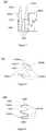
- Aneurysm is a permanent limitation expansion of the blood vessel and it is called an aneurysm when the vessel diameter is increased by more than 50% of its normal size. If an aneurysm is in the abdominal aorta, an abdominal aortic aneurysm is formed. Iliac aneurysm is usually defined as the case that the local extension of the iliac artery diameter exceeds 1.5cm. The iliac aneurysm is divided into isolated iliac aneurysm (see Fig. 1 ), independent iliac aneurysm (see Fig. 2 ), and iliac aneurysm accompanied by abdominal aortic aneurism (see Fig. 3 ).
- iliac aneurysm In 75% of the cases, iliac aneurysm is associated with abdominal artery. There are about 7.5% of the cases being isolated iliac aneurysm. The remaining aneurysm is the independent iliac aneurysm. In the United States, about 15,000 people die of abdominal aortic aneurysm (abdominal aortic aneurysm, AAA) rupture each year. It was believed in early reports that the iliac aneurysm having a diameter of more than 3cm was fatal and it is recommended to be treated by surgery. Although this disease is thought to involve only 2% of the general population, it tends to occur in the elderly, and with the arrival of China's aging population, its incidence is rising.
- the abdominal iliac artery 1 includes the renal artery 11 on the abdominal aorta, the abdominal aorta 12, the right arteria iliaca communis 13, the right internal iliac artery 14, the right external iliac artery 15, the left arteria iliaca communis 16, the left internal iliac artery 17 and the left external iliac artery 18.
- Single iliac aneurysm being not accompanied by abdominal aortic aneurysm, is known as an isolated iliac aneurysm, such as the right iliac aneurysm 19 as shown in Fig. 1 .
- Several iliac aneurysms being not accompanied by abdominal aortic aneurysm, are known as independent iliac aneurysm, such as the right iliac aneurysm 19 and the left iliac aneurysm 20 as shown in Fig. 2 .
- Aneurysms existing in abdominal aorta and iliac artery are called iliac aneurysms accompanied by abdominal aneurysm, such as the right iliac aneurysm 19, the left iliac aneurysm 20 and abdominal aortic aneurysm 21 as shown in Fig. 3 .
- Either open surgery or endovascular surgery can be used to repair the iliac aneurysms.
- Open repair can be carried out on all iliac aneurysms under anatomical conditions to replace arterial segments having pathological changes with artificial blood vessels, with good long-term results; however, the complications and mortality of iliac aneurysm open repair are equivalent to those of a major vascular surgery.
- a covered stent is usually adopted to cover the aneurysm.
- the commercially available covered stent is mainly composed of wire and PET (polyethylene terephthalate resin) membrane or ePTFE (polytetrafluoroethylene) membrane covered thereon, and the metal stent is made into a cylindrical or bifurcated metal frame.
- the compressed covered stent is delivered to the location of pathological changes and accurately released by a delivery system, and with the help of a developing system to cover the aneurysm, the stent isolates pathological changes and forms a new blood flow channel so that the aneurysm and arterial pressure are isolated, and the blood remaining in the lumen of the aneurysm gradually forms thrombosis and vascular tissue by muscularization.
- the expanded aneurysm wall contracts due to the negative pressure, thereby eliminating the hidden risks of tumor rupture and bleeding so as to achieve the purpose of healing.
- endovascular repair is adopted to treat iliac aneurysms, which can only block the bilateral internal iliac arteries or unilateral internal iliac artery, which may cause complications such as impotence, gluteus claudication and pelvic ischemia.
- Many clinical research data show that retaining at least one side of the internal iliac artery can significantly reduce the incidence of above-mentioned complications.
- the internal iliac bifurcated stent in the treatment of iliac aneurysms can open the bilateral internal iliac arteries and significantly reduce or avoid complications caused by the internal iliac artery blocking, which has distinct advantages.
- the proximal end and distal end of the stent can be defined by the blood flow, which flows from the proximal end to the distal end of the stent.
- the covered stent used for interventional treatment in the lumen of the iliac communis aneurysm affecting the internal iliac artery mainly consists of two types, respectively, a straight-tube type covered stent and a bifurcated stent graft, wherein the straight-tube type graft stent further includes two types, including one with a horn mouth at the distal end and the other one without a horn mouth at the distal end.
- the straight-tube type stent has a proximal end and a distal end.
- a bifurcated stent means that the stent has a proximal end of the body and two distal ends of the branch.
- the distal end of the stent When the straight-tube type covered stent without a horn mouth at the distal end is adopted, the distal end of the stent must be released in the external iliac artery in order to ensure that the distal end of the stent has a reliable anchoring and that no endo-leak will occur. Thus, the covered stent will block the internal iliac artery, which will result in pelvic ischemia, thereby causing the occurrence of complications such as gluteus claudication, colon ischemia, spinal cord ischemia, perineum necrosis and sexual dysfunction.
- the bifurcated stent graft is composed of a body, a main branch and a side branch part.
- the body and the side branch are released in the arteria iliaca communis, with the distal end of the side branch being approximate to the internal iliac artery and the distal end of the main branch is released within the external iliac artery involved by no aneurysm.
- an outer periphery covered stent is released into the internal iliac artery via the side branch and connected to the side branch. This ensures the circulation of the internal iliac artery and the complete isolation of the arteria iliaca communis.
- the bifurcated stent graft is a preferred option for the treatment of the arteria iliaca communis involving internal iliac artery.
- a common bifurcated stent graft comprises a body and a side branch, and an independent waveform ring is used to extend across the connection part of the body and the side branch of the stent, and surround a circle.
- the independent waveform ring is hard to set, and the axial origination site of the side branch is not fully attached with the waveform ring, so that the side branch has insufficient radial support force at this site, resulting problems such as the covering film being likely to retract due to insufficient support force at this site, and difficulties for the guidewire to enter the side branch through the body.
- a bifurcated stent graft comprises a body and a side branch that forms an acute angle with the body, the side branch comprising a covering film and a first bare stent disposed only on the covering film, a part of the first bare stent is positioned adjacent the boundary between the body and the covering film, and is located in the vertex angle area of the acute angle.
- the first bare stent comprises a plurality of proximal vertices and distal vertices, the connection lines of the plurality of distal vertices are annular, and at least a part of the plurality of proximal vertices is located in the vertex angle area.
- the first bare stent comprises a plurality of proximal vertices and distal vertices, the connection lines of the plurality of distal vertices are along the same circumference, and at least a part of the plurality of proximal vertices is located in the vertex angle area.
- the plurality of distal vertices is aligned with the distal end portion of the covering film.
- the body comprises a second bare stent positioned adjacent the boundary line, the second bare stent comprising two end support bars disposed at the opposite sides of the side branch, and the two end support bars are parallel to each other or symmetrical relative to the side branch.
- the tails of the end support bars are substantially smoothly rounded.
- the first bare stent is structured as a waveform open loop
- the side branch also comprises a third bare stent disposed on the covering film
- the third bare stent is structured as a waveform close loop and connected with the first bare stent.
- the body comprises a second bare stent positioned adjacent the boundary, the second bare stent comprising two end support bars disposed at the opposite sides of the side branch, and the two end support bars are parallel to each other or symmetrical relative to the side branch.
- the tails of the end support bars are substantially smoothly rounded.
- the covering film is retracted because the vertex angle area of the side branch is not supported by the bare stent, which not only results in the narrowing of the blood flow channel but also prevents the smooth entrance of the guidewire.
- a part of the first bare stent is attached to the vertex angle area, after the stent is released, the self-expanded part of the first bare stent can effectively support the vertex angle area of the side branch, so as to avoid the retraction of the covering film and facilitate the entrance of the guidewire.
- the technology for preparing the bare stent is simplified, and the first bare stent is disposed only on the side branch without going across the connection part of the body and the side branch, thus facilitating the waveform setting.
- the bifurcated stent graft will now be described more fully with reference to the related drawings. Preferred embodiments of the bifurcated stent grafts are shown in the drawings. However, the bifurcated stent graft can be achieved in many different ways and is not limited to the embodiments described herein. Conversely, these embodiments are provided so that this disclosure of the bifurcated stent graft will be more thorough and complete.
- the bifurcated stent graft 10 of one embodiment (hereinafter simply referred to as stent 10) comprises a body 100 and a side branch 200 that forms an acute angle with the body 100.
- the side branch 200 comprises a covering film 220 and a first bare stent 240 disposed only on the covering film 220. Part of the first bare stent 240 is approximate to a boundary line 230 of the body 100 and the covering film 220, and is located in a vertex angle area 250 of the acute angle.
- the boundary line 230 is the borderline connecting the body 100 and the covering film 220; the vertex angle area 250 is a part of the side branch 200, as shown by the portion of the dashed lines in Fig. 4 .
- the vertex angle area 250 is curved; the curve is formed by surrounding the boundary line 230 between the body 100 and the covering film 220 and the round section of the distal vertexes 270 through an acute angle; the round section preferably is parallel to the distal end of the side branch 200.
- the first bare stent 240 is attached to the covering film 220 by means of suturing or glue.
- the stent 10 has two states, a compressed state and an expanded state; the compressed stent 10 is constrained to the sheath of the delivery apparatus for delivery in blood vessels.
- Each bare stent on each covering film is released in a self-expanding manner after delivery at the target place, with the diameter of stent 10 being slightly larger than that of the vessel, so that stent 10 can be closely attached to the vascular wall to form a new blood flow channel.
- the included angle between the body 100 and the side branch 200 is an acute angle
- the covering film 220 will experienceshortening, which not only results in the narrowing of the blood flow channel, but also prevents the smooth entry of the guidewire.
- the self-expanded part of the first bare stent 240 can effectively support the vertex angle area 250 of the side branch 200, so as to avoid the retraction of the covering film 240 and facilitate the entry of the guidewire.
- a special bare stent attached to the vertex angle area 250 does not need to be additionally disposed on the first bare stent 240, and thus the technology for preparing the bare stent is simplified; furthermore, the first bare stent 240 is disposed only on the side branch 200 without extending across the connecting part of the body 100 and the side branch 200, thereby facilitating the waveform setting.
- the body 100 may comprise the body covering film 120 and the body bare stent 140 attached thereon; the body covering film 120 comprises axially the body segment 122, the connecting segment 124 and the long branch segment 126 in sequence; both the body segment 122 and the long branch segment 126 communicate with the connecting segment 124; after the stent 10 is implanted in the vessel, all covering films surround to form a new blood flow channel.
- Either end of the connecting segment 124 is connected with the body segment 122 and the long branch segment 126 respectively; all three can be integrally formed.
- the covering film 220 of the side branch 200 communicates with the connecting segment 124; the inner and outer surfaces of the connecting segment 124 are partially cylindrical.
- the body bare stent 140 comprises the body metal ring 142 disposed on the body segment 122, the second bare stent 144 disposed on the connecting segment 124 and the long branch metal ring 146 disposed on the long branch segment 126; both the body metal ring 142 and the long branch metal ring 146 can be multi-turn metal rings; the second bare stent 144 can be a single-turn; the multi-turn body metal ring 142, the single-turn second bare stent 144 and the multi-turn long branch metal ring 146 are arranged sequentially.
- the first bare stent 240 can be a single-turn metal ring. It is to be noted that the structure of the body 100 is not limiting the scope of this invention, as other configurations are available in other embodiments for the body 100.
- a first bare stent 240 comprises a plurality of proximal vertices 242a, 242b and 242c, and a plurality of distal vertices 244, and the proximal vertices are connected with the distal vertices 244 through support parts.
- the connection lines of the distal vertices 244 are annular (open loop or closed loop), preferably, the connection lines of the distal vertices 244 are positioned along the same circumference, and at least one part of the proximal vertices is positioned in a vertex angle area 250. More preferably, the distal vertices 244 are aligned with the distal end of a covering film 220.
- a part of the proximal vertices of the first bare stent 240 is positioned within the vertex angle area 250, such as the proximal vertices 242a and 242b, so that the first bare stent 240 has different waveform heights in the axial length direction of the covering film 220 of a side branch 200, and the waveform heights refer to the axial distances of the proximal vertex and the distal vertex 244. As shown in Fig.
- the axial distance h1 of the proximal vertices 242a and the distal vertices 244 is greater than the axial distance h2 of the proximal vertices 242b and the distal vertices 244, and the axial distance h2 of the proximal vertices 242b and the distal vertices 244 is greater than the axial distance h3 of the proximal vertices 242c and the distal vertices 244.
- the first bare stent 240 is designed into metal rings with different waveforms, so that other metal rings are not additionally arranged.
- the first bare stent 240 can be used for sufficiently supporting various parts of the side branch lumen 220, and a second bare stent 144 sufficiently supports a connecting segment 124.
- a guidewire easily enters the side branch lumen 220.
- the boundary line 230 and the vertex angle area 250 can be well supported, so that the situation where the covering film 220 is shortened, so that blood vessel channels are narrowed, can be avoided.
- the first bare stent 240 and the second bare stent 144 are interdependent, so that the waveform is easily shaped and the technology is simple.
- the second bare stent can also be provided in other structures or waveform structures of other materials, for example, the materials are not provided with elastic rings having swelling capacity, waveform rings made of polymers, and the like.
- the second bare stent 144 is an open loop single-ring waveform, and comprises a terminal end 1442 and a waveform, wherein the waveform comprises a plurality of proximal vertices 1444a and a plurality of distal vertices 1444b; the proximal vertices 1444a and the distal vertices 1444b are connected through the support part.
- the bare stent 144 is positioned adjacent the boundary line 230, and comprises two end support bars 1446 positioned on two opposite sides of the side branch 200, so as to support the boundary line 230.
- a waveform segment connected with the terminal end 1442 forms an end support bar 1446, wherein the terminal end 1442 is the tail of the end support bar 1446.
- two end support bars 1446 of the second bare stent 144 can be mutually parallel and or symmetrical relative to the side branch 200, can be parallel to the axial direction of the second bare stent 144, and can also be non-parallel to the axial direction of the second bare stent 144; of course, one of the end support bars 1446 can also be parallel to the axial direction of the second bare stent 144, and the other be non-parallel to the axial direction of the second bare stent 144.
- the terminal end 1442 can be fixed to a positionadjacent a long branch segment 126 of the connecting segment 124, and can be fixed at the position of a body segment 122; one proximal vertex can be fixed at the position adjacent the long branch segment 126, and the other terminal ends 1442 can be fixed at the position adjcent the body segment 122.
- the waveform of the second bare stent 144 can be a first waveform as shown in Fig. 10 and Fig. 11 , and the two end support bars 1446 and the second bare stent 144 are not parallel in the axial direction, and the two end support bars 1446 are mutually non-parallel.
- the two end support bars 1446 are symmetrical relative to the side branch 200, and the two terminal ends 1442 are fixed at the position adjacent the long branch segment 126 of the connecting segment 124.
- the wavefonn of the second bare stent 144 can also be a second waveform as shown in Fig. 12 to Fig. 15 , the two end support bars 1446 and the second bare stent 144 are parallel in the axial direction, the two end support bars are parallel with each other, and the two end support bars 1446 are symmetrical relative to the side branch 200.
- the two terminal ends 1442 are fixed at the position adjacent the body segment 122 of the connecting segment 124.
- the two terminal ends 1442 are fixed at the position adjacent the long branch segment 126 of the connecting segment 124.
- one terminal end 1442 is fixed at the position adjacent the long branch segment 126, and the other terminal end 1442 is fixed at the position adjacent the body segment 122.
- the end support bars 1446 are parallel to the axial direction of the metal ring, so that the end support bars 1446 on two sides of the opening of the side branch lumen 220 are symmetrical relative to the opening as well as the cross section of the tubular cavity, so that the end support bars 1446 can effectively support the side branch lumen 220, so as to facilitate the entry of the guidewire into the side branch lumen 220.
- the waveform of the second bare stent 144 can be a third waveform as shown in Fig. 16 and Fig. 17 , wherein one end support bar 1446 is parallel to the axial direction of the second bare stent 144, and the other end support bar 1446 is not parallel to the axial direction of the second bare stent 144.
- the two end support bars 1446 are not parallel with each other, and the two end support bars 1446 are asymmetric relative to the side branch 200. Compared with the construction shown in Fig. 10 to Fig. 15 , the two end support bars 1446 cannot be symmetrical relative to the side branch 200, so that the supporting effect is poor.
- the interior surface 1444c of the second bare stent 144 is on one cylindrical surface
- the exterior surface 1444d of the second bare stent 144 is on another cylindrical surface
- the interior surface 1444c of the second bare stent 144 and the exterior surface 1444d of the second bare stent 144 both only occupy part of the cylindrical surface.
- the second bare stent 144 is only fixed on the position of the connection segment 124, and does not extend to the side branch lumen 220; i.e., two terminal ends 1442 both terminate at the junction of the two sides of the body 100 and the side branch 200, and can completely support the connecting segment 124 to form an unobstructed blood flow channel.
- two terminal ends 1442 both terminate at the junction of the two sides of the body 100 and the side branch 200, and can completely support the connecting segment 124 to form an unobstructed blood flow channel.
- the two terminal ends 1442 of the second bare stent 144 can abut on two proximal vertices 242b of the first bare stent 240 respectively.
- the terminal ends 1442 can be designed as a smoothly rounded structure, which can generally be ring shaped, oval shaped, or any curve shaped, and so on. Specifically, the terminal ends 1442 can be generally ring shaped, and in the above-mentioned embodiments, the terminal eds 1442 are ring shaped.
- the multi-turn metal rings of the body metal ring 142 and the long branch metal ring 146 both can be a closed independent wave loop, and if there are other metal rings on the stent 10, the other metal rings also can be a closed independent wave loop.
- the body metal ring 142 includes a plurality of proximal vertices 1442a and a plurality of distal vertices 1442b, wherein the proximal vertices 1442a are connected with the distal vertices 1442b through a support part.
- the interior surface 1442c of the body metal ring 142 is on one cylindrical surface
- the exterior surface 1442d of the body metal ring 142 is on another cylindrical surface.
- the multi-turn metal rings of the body metal ring 142 and the long branch metal ring 146 both have the same or a similar shape, for example a Z-shaped wave or other waveforms.
- a metal wire can be woven or cut into a desired waveform, and after the heat setting of the metal wire via a mold, the steel socket 300 as shown in Fig. 7 and Fig. 21 is used as a socket joint to connect both ends of the metal wire, and the mechanical compression method is used to fixedly connect the metal wire and the steel socket 300, thereby forming a metal ring.
- the metal wire can be a nickel-titanium alloy wire, for example a nickel-titanium alloy wire with the wire diameter of 0.40 mm.
- surface covering films of the multi-turn metal rings are spaced intermittently and sequentially, and polyethyleneterephthalate (PET) or Polytetranuoroethene (PTFE) can be optionally used as a material for the covering films.
- PET polyethyleneterephthalate
- PTFE Polytetranuoroethene
- FIG. 23 Schematic diagrams of the implantation of the bifurcated stent graft 10 in Fig. 4 being implanted into the abdominal iliac arteries are shown in Fig. 23, Fig. 24 and Fig. 25 .
- FIG. 24 A schematic diagram showing how the iliac artery bifurcated stent graft 10 in Fig. 4 combined with the peripheral covering stent 30 opens up the bilateral iliac artery is shown in Fig. 24 .
- stent 10 can effectively isolate the blood flow and the artery aneurysm, and the relatively good radial support force of the bifurcation part can maintain the stent 10 continuously in an unobstructed state, thereby guaranteeing that the blood flow is unobstructed in every lumen.
- the diameter of the body segment 122 can be as large as that of the lumen of the long branch stent 10. In another embodiment, with reference to Fig. 27 , the diameter of the body segment 122 can also be designed to be not as large as that of the long branch segment 126 according to desired requirements, for example, the diameter of the body segment 122 is larger than that of the long branch segment 126.
- the first bare stent 260 can also be structured as a waveform open loop.
- the side branch 200 also comprises a third bare stent 280 disposed on the covering film 220, and the third bare stent 280 is structured as a waveform close loop and connected with the first bare stent 260.
- the first bare stent 260 is combined with the third bare stent 280, in order to completely support the side branch 200.
- most or all of the first bare stent 260 is disposed within the top corner region 250 for supporting the top corner region 250, and the second bare stent 280 is used for supporting the other regions of the side branch 200.
- the first bare stent 260 and the second bare stent 280 can be connected and fixed together via the steel socket 300.
- the first bare stent 260 can be a wave loop with non-equal length waves and/or non-equal heights, the distal vertices of the first bare stent 260, i.e. one end proximate to the second bare stent 280 is on the same plane perpendicular to the axis of the side branch 200.
- the number of the proximal vertices of the first bare stent 260 can be one or more than one; in this example, the number of the proximal vertices of the first bare stent 260 is more than one, and the height of the proximal vertices at the middle position on the plane perpendicular to the axis of the side branch 200 is larger than that of the proximal vertices at either end position.
- the number of the second bare stent 280 can be one or more than one; in this example, the number of the second bare stent 280 is one, and the second bare stent 280 is a wave loop with average equal length waves and/or non-equal heights.
- the first bare stent 260 and the second bare stent 280 are both fixed on the side branch lumen 220, and can completely support the side branch lumen 220.
- the other parts of this embodiment can be the same as those shown in Fig. 4 to Fig. 27 .
Landscapes
- Health & Medical Sciences (AREA)
- Engineering & Computer Science (AREA)
- Biomedical Technology (AREA)
- Heart & Thoracic Surgery (AREA)
- Public Health (AREA)
- Transplantation (AREA)
- Cardiology (AREA)
- Veterinary Medicine (AREA)
- Oral & Maxillofacial Surgery (AREA)
- Vascular Medicine (AREA)
- Life Sciences & Earth Sciences (AREA)
- Animal Behavior & Ethology (AREA)
- General Health & Medical Sciences (AREA)
- Gastroenterology & Hepatology (AREA)
- Pulmonology (AREA)
- Physics & Mathematics (AREA)
- Optics & Photonics (AREA)
- Prostheses (AREA)
Description
- The present invention relates to the technical field of medical devices, particularly to a bifurcated stent graft.
- Aneurysm is a permanent limitation expansion of the blood vessel and it is called an aneurysm when the vessel diameter is increased by more than 50% of its normal size. If an aneurysm is in the abdominal aorta, an abdominal aortic aneurysm is formed. Iliac aneurysm is usually defined as the case that the local extension of the iliac artery diameter exceeds 1.5cm. The iliac aneurysm is divided into isolated iliac aneurysm (see
Fig. 1 ), independent iliac aneurysm (seeFig. 2 ), and iliac aneurysm accompanied by abdominal aortic aneurism (seeFig. 3 ). In 75% of the cases, iliac aneurysm is associated with abdominal artery. There are about 7.5% of the cases being isolated iliac aneurysm. The remaining aneurysm is the independent iliac aneurysm. In the United States, about 15,000 people die of abdominal aortic aneurysm (abdominal aortic aneurysm, AAA) rupture each year. It was believed in early reports that the iliac aneurysm having a diameter of more than 3cm was fatal and it is recommended to be treated by surgery. Although this disease is thought to involve only 2% of the general population, it tends to occur in the elderly, and with the arrival of China's aging population, its incidence is rising. - As shown in
Fig. 1 to Fig. 3 , theabdominal iliac artery 1 includes therenal artery 11 on the abdominal aorta, theabdominal aorta 12, the right arteria iliaca communis 13, the rightinternal iliac artery 14, the rightexternal iliac artery 15, the left arteria iliaca communis 16, the leftinternal iliac artery 17 and the leftexternal iliac artery 18. The protein degradation of connective tissues in arterial walls, inflammation and immune responses, as well as other factors, result in the loss of elastin in the middle and outer membranes, which causes the extension of tumors. Single iliac aneurysm, being not accompanied by abdominal aortic aneurysm, is known as an isolated iliac aneurysm, such as theright iliac aneurysm 19 as shown inFig. 1 . Several iliac aneurysms, being not accompanied by abdominal aortic aneurysm, are known as independent iliac aneurysm, such as theright iliac aneurysm 19 and theleft iliac aneurysm 20 as shown inFig. 2 . Aneurysms existing in abdominal aorta and iliac artery are called iliac aneurysms accompanied by abdominal aneurysm, such as theright iliac aneurysm 19, theleft iliac aneurysm 20 and abdominalaortic aneurysm 21 as shown inFig. 3 . - Either open surgery or endovascular surgery can be used to repair the iliac aneurysms. Open repair can be carried out on all iliac aneurysms under anatomical conditions to replace arterial segments having pathological changes with artificial blood vessels, with good long-term results; however, the complications and mortality of iliac aneurysm open repair are equivalent to those of a major vascular surgery.
- In the minimally invasive interventional treatment techniques which make use of endovascular exclusion principle, a covered stent is usually adopted to cover the aneurysm. At present, the commercially available covered stent is mainly composed of wire and PET (polyethylene terephthalate resin) membrane or ePTFE (polytetrafluoroethylene) membrane covered thereon, and the metal stent is made into a cylindrical or bifurcated metal frame. The compressed covered stent is delivered to the location of pathological changes and accurately released by a delivery system, and with the help of a developing system to cover the aneurysm, the stent isolates pathological changes and forms a new blood flow channel so that the aneurysm and arterial pressure are isolated, and the blood remaining in the lumen of the aneurysm gradually forms thrombosis and vascular tissue by muscularization. The expanded aneurysm wall contracts due to the negative pressure, thereby eliminating the hidden risks of tumor rupture and bleeding so as to achieve the purpose of healing.
- In comparison, at present, endovascular repair is adopted to treat iliac aneurysms, which can only block the bilateral internal iliac arteries or unilateral internal iliac artery, which may cause complications such as impotence, gluteus claudication and pelvic ischemia. Many clinical research data show that retaining at least one side of the internal iliac artery can significantly reduce the incidence of above-mentioned complications. At present, it has been reported in the literature that the internal iliac bifurcated stent in the treatment of iliac aneurysms can open the bilateral internal iliac arteries and significantly reduce or avoid complications caused by the internal iliac artery blocking, which has distinct advantages.
- The proximal end and distal end of the stent can be defined by the blood flow, which flows from the proximal end to the distal end of the stent.
- Currently, the covered stent used for interventional treatment in the lumen of the iliac communis aneurysm affecting the internal iliac artery mainly consists of two types, respectively, a straight-tube type covered stent and a bifurcated stent graft, wherein the straight-tube type graft stent further includes two types, including one with a horn mouth at the distal end and the other one without a horn mouth at the distal end. The straight-tube type stent has a proximal end and a distal end. A bifurcated stent means that the stent has a proximal end of the body and two distal ends of the branch.
- When the straight-tube type covered stent without a horn mouth at the distal end is adopted, the distal end of the stent must be released in the external iliac artery in order to ensure that the distal end of the stent has a reliable anchoring and that no endo-leak will occur. Thus, the covered stent will block the internal iliac artery, which will result in pelvic ischemia, thereby causing the occurrence of complications such as gluteus claudication, colon ischemia, spinal cord ischemia, perineum necrosis and sexual dysfunction.
- When the straight-tube type covered stent with a horn mouth at the distal end is adopted, the distal end of the stent may be released approximate to the opening of the internal iliac artery and the stent with a horn mouth at the distal end is attached to the arteria iliaca communis wall. Thus, circulation of the internal iliac artery can be ensured; however, the stent does not completely isolate the arteria iliaca communis, which still carries the risk of rupture.
The bifurcated stent graft is composed of a body, a main branch and a side branch part. The body and the side branch are released in the arteria iliaca communis, with the distal end of the side branch being approximate to the internal iliac artery and the distal end of the main branch is released within the external iliac artery involved by no aneurysm. After the bifurcated stent graft has been completely released, an outer periphery covered stent is released into the internal iliac artery via the side branch and connected to the side branch. This ensures the circulation of the internal iliac artery and the complete isolation of the arteria iliaca communis. In summary, the bifurcated stent graft is a preferred option for the treatment of the arteria iliaca communis involving internal iliac artery. A common bifurcated stent graft comprises a body and a side branch, and an independent waveform ring is used to extend across the connection part of the body and the side branch of the stent, and surround a circle. However, because of irregular shape at the boundary between the body and the side branch, the independent waveform ring is hard to set, and the axial origination site of the side branch is not fully attached with the waveform ring, so that the side branch has insufficient radial support force at this site, resulting problems such as the covering film being likely to retract due to insufficient support force at this site, and difficulties for the guidewire to enter the side branch through the body. - Based on the above, there is a need to provide a bifurcated stent graft to address the problems that the support force at the boundary between the body and the side branch is insufficient, and that it is difficult for the guidewire to enter.
- A bifurcated stent graft comprises a body and a side branch that forms an acute angle with the body, the side branch comprising a covering film and a first bare stent disposed only on the covering film, a part of the first bare stent is positioned adjacent the boundary between the body and the covering film, and is located in the vertex angle area of the acute angle.
- In one of the embodiments, the first bare stent comprises a plurality of proximal vertices and distal vertices, the connection lines of the plurality of distal vertices are annular, and at least a part of the plurality of proximal vertices is located in the vertex angle area.
- In one of the embodiments, the first bare stent comprises a plurality of proximal vertices and distal vertices, the connection lines of the plurality of distal vertices are along the same circumference, and at least a part of the plurality of proximal vertices is located in the vertex angle area.
- In one of the embodiments, the plurality of distal vertices is aligned with the distal end portion of the covering film.
- In one of the embodiments, the body comprises a second bare stent positioned adjacent the boundary line, the second bare stent comprising two end support bars disposed at the opposite sides of the side branch, and the two end support bars are parallel to each other or symmetrical relative to the side branch.
- In one of the embodiments, the tails of the end support bars are substantially smoothly rounded.
- In one of the embodiments, the first bare stent is structured as a waveform open loop, the side branch also comprises a third bare stent disposed on the covering film, and the third bare stent is structured as a waveform close loop and connected with the first bare stent.
- In one of the embodiments, the body comprises a second bare stent positioned adjacent the boundary, the second bare stent comprising two end support bars disposed at the opposite sides of the side branch, and the two end support bars are parallel to each other or symmetrical relative to the side branch.
- In one of the embodiments, the tails of the end support bars are substantially smoothly rounded.In the above bifurcated stent graft, since the included angle between the body and the side branch is an acute angle, the covering film is retracted because the vertex angle area of the side branch is not supported by the bare stent, which not only results in the narrowing of the blood flow channel but also prevents the smooth entrance of the guidewire. In this application, a part of the first bare stent is attached to the vertex angle area, after the stent is released, the self-expanded part of the first bare stent can effectively support the vertex angle area of the side branch, so as to avoid the retraction of the covering film and facilitate the entrance of the guidewire. Meanwhile, there is no need for an additional bare stent to attach to the vertex angle area on the basis of the first bare stent, thus the technology for preparing the bare stent is simplified, and the first bare stent is disposed only on the side branch without going across the connection part of the body and the side branch, thus facilitating the waveform setting.
-
-
Fig. 1 is a schematic view of an isolated iliac artery aneurysm; -
Fig. 2 is a schematic view of an independent iliac artery aneurysm; -
Fig. 3 is a schematic view of an iliac artery aneurysm accompanied with abdominal arterial aneurysm; -
Fig. 4 is a schematic view of one embodiment of a bifurcated stent graft; -
Fig. 5 is a schematic view of a covering film of the bifurcated stent graft and a body covering film ofFig. 4 ; -
Fig. 6 is a schematic view of a first bare stent of the bifurcated stent graft and a body bare stent ofFig. 4 ; -
Fig. 7 is a schematic view of a first bare stent of the bifurcated stent graft ofFig. 4 ; -
Fig. 8 is a schematic view of a second bare stent of the bifurcated stent graft ofFig. 4 ; -
Fig. 9 is a side view of a second bare stent of the bifurcated stent graft ofFig. 4 ; -
Fig. 10 is a schematic view of a first waveform of the bifurcated stent graft ofFig. 4 ; -
Fig. 11 is a schematic view of the position of a first waveform and covering film of the bifurcated stent graft ofFig. 10 ; -
Fig. 12 is a schematic view of a second waveform of the bifurcated stent graft ofFig. 4 ; -
Fig. 13 is a schematic view of the position of a second waveform and covering film of the bifurcated stent graft ofFig. 12 ; -
Fig. 14 is another schematic view of the position of a second waveform and covering film of the bifurcated stent graft ofFig. 12 ; -
Fig. 15 is still another schematic view of the position of a second waveform and covering film of the bifurcated stent graft ofFig. 12 ; -
Fig. 16 is a schematic view of a third waveform of the bifurcated stent graft ofFig. 4 ; -
Fig. 17 is a schematic view of the position of a third waveform and covering film of the bifurcated stent graft ofFig. 16 ; -
Fig. 18 is a top view of a second bare stent of the bifurcated stent graft ofFig. 4 ; -
Fig. 19 is a schematic view of a first bare stent and a second bare stent of the bifurcated stent graft ofFig. 4 ; -
Fig. 20 is a perspective view of a body metal ring of the bifurcated stent graft ofFig. 4 ; -
Fig. 21 is a side view of a body metal ring of the bifurcated stent graft ofFig. 4 ; -
Fig. 22 is a top view of a body metal ring of the bifurcated stent graft ofFig. 4 ; -
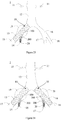
Fig. 23 is an illustration of the bifurcated stent graft implanted into the unilateral isolated iliac communis aneurysm ofFig. 4 ; -
Fig. 24 is an illustration of the bifurcated stent graft implanted into the bilateral isolated iliac communis aneurysm ofFig. 4 ; -
Fig. 25 is an illustration of the bifurcated stent graft in combination with an abdominal aortic bifurcated stent graft for the treatment of abdominal iliac aneurysm accompanied with abdominal aortic aneurysm ofFig. 4 ; -
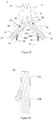
Fig. 26 is a schematic diagram of another embodiment of the bifurcated stent graft; -
Fig. 27 is a schematic diagram of yet another embodiment of the bifurcated stent graft; -
Fig. 28 is a schematic diagram of yet another embodiment of the bifurcated stent graft; -
Fig. 29 is a schematic diagram of yet another embodiment of the bifurcated stent graft. - In order to fully understand the invention, the bifurcated stent graft will now be described more fully with reference to the related drawings. Preferred embodiments of the bifurcated stent grafts are shown in the drawings. However, the bifurcated stent graft can be achieved in many different ways and is not limited to the embodiments described herein. Conversely, these embodiments are provided so that this disclosure of the bifurcated stent graft will be more thorough and complete.
- It will be understood that when an element is referred to as being "fixed on" another element, it can be directly on the other element or intervening elements may also be present. When an element is referred to as being "connected with" another element, it can be directly connected with the other element or intervening elements may also be present. The terms "vertical", "horizontal", "left", "right" and the like are used herein for the purpose of explanation only and not intended to represent the only examples that can be practiced.
- Unless otherwise defined, all technical and scientific terms used herein have the same meaning as commonly understood by those skilled in the art to which this invention belongs. The terms used in the description of the bifurcated stent graft herein are for the purpose of describing particular examples only and are not intended to limit the invention. As used herein, the term "and / or" includes any and all combinations of one or more of the associated listed items.
- As shown in
Fig. 4 , thebifurcated stent graft 10 of one embodiment (hereinafter simply referred to as stent 10) comprises abody 100 and aside branch 200 that forms an acute angle with thebody 100. Theside branch 200 comprises acovering film 220 and a firstbare stent 240 disposed only on thecovering film 220. Part of the firstbare stent 240 is approximate to aboundary line 230 of thebody 100 and thecovering film 220, and is located in avertex angle area 250 of the acute angle. - The
boundary line 230 is the borderline connecting thebody 100 and thecovering film 220; thevertex angle area 250 is a part of theside branch 200, as shown by the portion of the dashed lines inFig. 4 . Thevertex angle area 250 is curved; the curve is formed by surrounding theboundary line 230 between thebody 100 and thecovering film 220 and the round section of thedistal vertexes 270 through an acute angle; the round section preferably is parallel to the distal end of theside branch 200. In one embodiment, the firstbare stent 240 is attached to thecovering film 220 by means of suturing or glue. Thestent 10 has two states, a compressed state and an expanded state; thecompressed stent 10 is constrained to the sheath of the delivery apparatus for delivery in blood vessels. Each bare stent on each covering film is released in a self-expanding manner after delivery at the target place, with the diameter ofstent 10 being slightly larger than that of the vessel, so thatstent 10 can be closely attached to the vascular wall to form a new blood flow channel. - As the included angle between the
body 100 and theside branch 200 is an acute angle, when no bare stent supports theside branch 200 from inside approximate to theboundary line 230 proximally connecting them (i.e. the vertex angle area 250), the coveringfilm 220 will experienceshortening, which not only results in the narrowing of the blood flow channel, but also prevents the smooth entry of the guidewire. In this invention, due to the fact that part of the firstbare stent 240 is attached to thevertex angle area 250, after thestent 10 is released, the self-expanded part of the firstbare stent 240 can effectively support thevertex angle area 250 of theside branch 200, so as to avoid the retraction of thecovering film 240 and facilitate the entry of the guidewire. Meanwhile, a special bare stent attached to thevertex angle area 250 does not need to be additionally disposed on the firstbare stent 240, and thus the technology for preparing the bare stent is simplified; furthermore, the firstbare stent 240 is disposed only on theside branch 200 without extending across the connecting part of thebody 100 and theside branch 200, thereby facilitating the waveform setting. - Meanwhile, with reference to
Figs. 5 and 6 , in one of the embodiments, thebody 100 may comprise thebody covering film 120 and the bodybare stent 140 attached thereon; thebody covering film 120 comprises axially thebody segment 122, the connectingsegment 124 and thelong branch segment 126 in sequence; both thebody segment 122 and thelong branch segment 126 communicate with the connectingsegment 124; after thestent 10 is implanted in the vessel, all covering films surround to form a new blood flow channel. Either end of the connectingsegment 124 is connected with thebody segment 122 and thelong branch segment 126 respectively; all three can be integrally formed. Thecovering film 220 of theside branch 200 communicates with the connectingsegment 124; the inner and outer surfaces of the connectingsegment 124 are partially cylindrical. - The body
bare stent 140 comprises thebody metal ring 142 disposed on thebody segment 122, the secondbare stent 144 disposed on the connectingsegment 124 and the longbranch metal ring 146 disposed on thelong branch segment 126; both thebody metal ring 142 and the longbranch metal ring 146 can be multi-turn metal rings; the secondbare stent 144 can be a single-turn; the multi-turnbody metal ring 142, the single-turn secondbare stent 144 and the multi-turn longbranch metal ring 146 are arranged sequentially. In this embodiment, the firstbare stent 240 can be a single-turn metal ring. It is to be noted that the structure of thebody 100 is not limiting the scope of this invention, as other configurations are available in other embodiments for thebody 100. - At the same time, with reference to
Fig. 7 , a firstbare stent 240 comprises a plurality ofproximal vertices distal vertices 244, and the proximal vertices are connected with thedistal vertices 244 through support parts. The connection lines of thedistal vertices 244 are annular (open loop or closed loop), preferably, the connection lines of thedistal vertices 244 are positioned along the same circumference, and at least one part of the proximal vertices is positioned in avertex angle area 250. More preferably, thedistal vertices 244 are aligned with the distal end of acovering film 220. - A part of the proximal vertices of the first
bare stent 240 is positioned within thevertex angle area 250, such as theproximal vertices bare stent 240 has different waveform heights in the axial length direction of thecovering film 220 of aside branch 200, and the waveform heights refer to the axial distances of the proximal vertex and thedistal vertex 244. As shown inFig. 7 , according to the position distribution of the proximal vertices relative to thevertex angle area 250, the axial distance h1 of theproximal vertices 242a and thedistal vertices 244 is greater than the axial distance h2 of theproximal vertices 242b and thedistal vertices 244, and the axial distance h2 of theproximal vertices 242b and thedistal vertices 244 is greater than the axial distance h3 of theproximal vertices 242c and thedistal vertices 244. According to the differences of the axial lengths ofside branch lumen 220, the firstbare stent 240 is designed into metal rings with different waveforms, so that other metal rings are not additionally arranged. The firstbare stent 240 can be used for sufficiently supporting various parts of theside branch lumen 220, and a secondbare stent 144 sufficiently supports a connectingsegment 124. Under the sufficient support of theside branch 200 and the connectingsegment 124, on one side, a guidewire easily enters theside branch lumen 220. On the other hand, theboundary line 230 and thevertex angle area 250 can be well supported, so that the situation where thecovering film 220 is shortened, so that blood vessel channels are narrowed, can be avoided. Meanwhile, the firstbare stent 240 and the secondbare stent 144 are interdependent, so that the waveform is easily shaped and the technology is simple. - In other embodiments, the second bare stent can also be provided in other structures or waveform structures of other materials, for example, the materials are not provided with elastic rings having swelling capacity, waveform rings made of polymers, and the like. In the embodiment, referring to
Fig. 8 and Fig. 9 , specifically, the secondbare stent 144 is an open loop single-ring waveform, and comprises aterminal end 1442 and a waveform, wherein the waveform comprises a plurality ofproximal vertices 1444a and a plurality ofdistal vertices 1444b; theproximal vertices 1444a and thedistal vertices 1444b are connected through the support part. Thebare stent 144 is positioned adjacent theboundary line 230, and comprises two end support bars 1446 positioned on two opposite sides of theside branch 200, so as to support theboundary line 230. A waveform segment connected with theterminal end 1442 forms anend support bar 1446, wherein theterminal end 1442 is the tail of theend support bar 1446. - Further, two end support bars 1446 of the second
bare stent 144 can be mutually parallel and or symmetrical relative to theside branch 200, can be parallel to the axial direction of the secondbare stent 144, and can also be non-parallel to the axial direction of the secondbare stent 144; of course, one of the end support bars 1446 can also be parallel to the axial direction of the secondbare stent 144, and the other be non-parallel to the axial direction of the secondbare stent 144. Theterminal end 1442 can be fixed to a positionadjacent along branch segment 126 of the connectingsegment 124, and can be fixed at the position of abody segment 122; one proximal vertex can be fixed at the position adjacent thelong branch segment 126, and the other terminal ends 1442 can be fixed at the position adjcent thebody segment 122. - In one embodment, the waveform of the second
bare stent 144 can be a first waveform as shown inFig. 10 and Fig. 11 , and the two end support bars 1446 and the secondbare stent 144 are not parallel in the axial direction, and the two end support bars 1446 are mutually non-parallel. The two end support bars 1446 are symmetrical relative to theside branch 200, and the two terminal ends 1442 are fixed at the position adjacent thelong branch segment 126 of the connectingsegment 124. - The wavefonn of the second
bare stent 144 can also be a second waveform as shown inFig. 12 to Fig. 15 , the two end support bars 1446 and the secondbare stent 144 are parallel in the axial direction, the two end support bars are parallel with each other, and the two end support bars 1446 are symmetrical relative to theside branch 200. In the embodiment as shown inFig.13 , the two terminal ends 1442 are fixed at the position adjacent thebody segment 122 of the connectingsegment 124. In the embodiment ofFig. 14 , the two terminal ends 1442 are fixed at the position adjacent thelong branch segment 126 of the connectingsegment 124. In the embodiment ofFig. 15 , oneterminal end 1442 is fixed at the position adjacent thelong branch segment 126, and the otherterminal end 1442 is fixed at the position adjacent thebody segment 122. The end support bars 1446 are parallel to the axial direction of the metal ring, so that the end support bars 1446 on two sides of the opening of theside branch lumen 220 are symmetrical relative to the opening as well as the cross section of the tubular cavity, so that the end support bars 1446 can effectively support theside branch lumen 220, so as to facilitate the entry of the guidewire into theside branch lumen 220. - The waveform of the second
bare stent 144 can be a third waveform as shown inFig. 16 and Fig. 17 , wherein oneend support bar 1446 is parallel to the axial direction of the secondbare stent 144, and the otherend support bar 1446 is not parallel to the axial direction of the secondbare stent 144. The two end support bars 1446 are not parallel with each other, and the two end support bars 1446 are asymmetric relative to theside branch 200. Compared with the construction shown inFig. 10 to Fig. 15 , the two end support bars 1446 cannot be symmetrical relative to theside branch 200, so that the supporting effect is poor. - Meanwhile, with reference to
Fig. 18 , theinterior surface 1444c of the secondbare stent 144 is on one cylindrical surface, theexterior surface 1444d of the secondbare stent 144 is on another cylindrical surface, and theinterior surface 1444c of the secondbare stent 144 and theexterior surface 1444d of the secondbare stent 144 both only occupy part of the cylindrical surface. The secondbare stent 144 is only fixed on the position of theconnection segment 124, and does not extend to theside branch lumen 220; i.e., two terminal ends 1442 both terminate at the junction of the two sides of thebody 100 and theside branch 200, and can completely support the connectingsegment 124 to form an unobstructed blood flow channel. Meanwhile, with reference toFig. 19 , in the embodiment that the terminal ends are fixed on the position of the connectingsegment 124 adjacent thelong branch segment 126, the two terminal ends 1442 of the secondbare stent 144 can abut on twoproximal vertices 242b of the firstbare stent 240 respectively. - In order to avoid scratching the blood vessels, sharp parts should not be formed on the second
bare stent 144, and the terminal ends 1442 can be designed as a smoothly rounded structure, which can generally be ring shaped, oval shaped, or any curve shaped, and so on. Specifically, the terminal ends 1442 can be generally ring shaped, and in the above-mentioned embodiments, theterminal eds 1442 are ring shaped. - The multi-turn metal rings of the
body metal ring 142 and the longbranch metal ring 146 both can be a closed independent wave loop, and if there are other metal rings on thestent 10, the other metal rings also can be a closed independent wave loop. Meanwhile, with reference toFig. 20 and Fig. 21 , taking thebody metal ring 142 for example, thebody metal ring 142 includes a plurality of proximal vertices 1442a and a plurality of distal vertices 1442b, wherein the proximal vertices 1442a are connected with the distal vertices 1442b through a support part. Meanwhile, with reference toFig. 22 , the interior surface 1442c of thebody metal ring 142 is on one cylindrical surface, and the exterior surface 1442d of thebody metal ring 142 is on another cylindrical surface. The multi-turn metal rings of thebody metal ring 142 and the longbranch metal ring 146 both have the same or a similar shape, for example a Z-shaped wave or other waveforms. - During the fabrication of the above-mentioned first
bare stent 240, thebody metal ring 142 and the longbranch metal ring 146, a metal wire can be woven or cut into a desired waveform, and after the heat setting of the metal wire via a mold, thesteel socket 300 as shown inFig. 7 andFig. 21 is used as a socket joint to connect both ends of the metal wire, and the mechanical compression method is used to fixedly connect the metal wire and thesteel socket 300, thereby forming a metal ring. The metal wire can be a nickel-titanium alloy wire, for example a nickel-titanium alloy wire with the wire diameter of 0.40 mm. After the fabrication of the multi-turn metal rings is completed, surface covering films of the multi-turn metal rings are spaced intermittently and sequentially, and polyethyleneterephthalate (PET) or Polytetranuoroethene (PTFE) can be optionally used as a material for the covering films. - Schematic diagrams of the implantation of the
bifurcated stent graft 10 inFig. 4 being implanted into the abdominal iliac arteries are shown inFig. 23, Fig. 24 andFig. 25 . A schematic diagram showing how the iliac artery bifurcatedstent graft 10 inFig. 4 combined with theperipheral covering stent 30 opens up the right internal iliac artery is shown inFig. 23 . A schematic diagram showing how the iliac artery bifurcatedstent graft 10 inFig. 4 combined with theperipheral covering stent 30 opens up the bilateral iliac artery is shown inFig. 24 . A schematic diagram showing how the iliac artery bifurcatedstent graft 10 inFig. 4 combined with theperipheral covering stent 30 and abdominal mainbifurcated stent graft 50 treats the arteria iliaca communis accompanied with the abdominal aortic aneurysm is shown inFig. 25 . Thestent 10 can effectively isolate the blood flow and the artery aneurysm, and the relatively good radial support force of the bifurcation part can maintain thestent 10 continuously in an unobstructed state, thereby guaranteeing that the blood flow is unobstructed in every lumen. - In one embodiment, with reference to
Fig. 26 , the diameter of thebody segment 122 can be as large as that of the lumen of thelong branch stent 10. In another embodiment, with reference toFig. 27 , the diameter of thebody segment 122 can also be designed to be not as large as that of thelong branch segment 126 according to desired requirements, for example, the diameter of thebody segment 122 is larger than that of thelong branch segment 126. - As shown in
Fig. 28 and Fig. 29 , in another embodiment, the firstbare stent 260 can also be structured as a waveform open loop. Theside branch 200 also comprises a thirdbare stent 280 disposed on thecovering film 220, and the thirdbare stent 280 is structured as a waveform close loop and connected with the firstbare stent 260. The firstbare stent 260 is combined with the thirdbare stent 280, in order to completely support theside branch 200. Preferably, most or all of the firstbare stent 260 is disposed within thetop corner region 250 for supporting thetop corner region 250, and the secondbare stent 280 is used for supporting the other regions of theside branch 200. - In an embodiment, the first
bare stent 260 and the secondbare stent 280 can be connected and fixed together via thesteel socket 300. The firstbare stent 260 can be a wave loop with non-equal length waves and/or non-equal heights, the distal vertices of the firstbare stent 260, i.e. one end proximate to the secondbare stent 280 is on the same plane perpendicular to the axis of theside branch 200. The number of the proximal vertices of the firstbare stent 260 can be one or more than one; in this example, the number of the proximal vertices of the firstbare stent 260 is more than one, and the height of the proximal vertices at the middle position on the plane perpendicular to the axis of theside branch 200 is larger than that of the proximal vertices at either end position. The number of the secondbare stent 280 can be one or more than one; in this example, the number of the secondbare stent 280 is one, and the secondbare stent 280 is a wave loop with average equal length waves and/or non-equal heights. The firstbare stent 260 and the secondbare stent 280 are both fixed on theside branch lumen 220, and can completely support theside branch lumen 220. The other parts of this embodiment can be the same as those shown inFig. 4 to Fig. 27 . - The above embodiments only express a few embodiments of the present invention, and the description thereof is relatively specific and particular, but these should not thereby be construed as limitations on the scope of the present invention. It should be noted that for those skilled in the art, it will be appreciated that various changes and modifications may be made to the invention as described herein without departing from the spirit and scope thereof, which belongs to the protective scope of the present invention. Therefore, the protective scope of the present invention should only be determined by the appended claims.
Claims (9)
- A bifurcated stent graft, characterized in comprising a body and a side branch that forms an acute angle with the body; the side branch comprising a covering film and a first bare stent disposed only on the covering film; a part of the first bare stent is positioned adjacent a boundary line of the body and the covering film, and is located in a vertex angle area of the acute angle.
- The bifurcated stent graft of claim 1, characterized in that the first bare stent comprises a plurality of proximal vertices and distal vertices; the connection line of the plurality of distal vertices is annular; and at least a part of the plurality of proximal vertices is located in the vertex angle area.
- The bifurcated stent graft of claim 1, characterized in that the first bare stent comprises a plurality of proximal vertices and distal vertices; the connection line of the plurality of distal vertices is located along the same circumference; at least a part of the plurality of proximal vertices is located in the vertex angle area.
- The bifurcated stent graft of claim 3, characterized in that the plurality of distal vertices are aligned with the distal end of the covering film.
- The bifurcated stent graft according to any of the claims 1 to 4, characterized in that the body comprises a second bare stent positioned adjacent the boundary line; the second bare stent comprises two end support bars disposed at the opposite sides of the side branch; and the two end support bars are parallel to each other or symmetrical relative to the side branch.
- The bifurcated stent graft of claim 5, characterized in that the tails of the end support bars are smoothly rounded.
- The bifurcated stent graft according to any of the claims 1 to 3, characterized in that the first bare stent is structured as a waveform open loop; the side branch also comprises a third bare stent disposed on the covering film; the third bare stent is structured as a waveform close loop and connected with the first bare stent.
- The bifurcated stent graft according to claim 7, characterized in that the body comprises a second bare stent positioned adjacent the boundary line; the second bare stent comprises two end support bars disposed at the opposite sides of the side branch; the two end support bars are parallel to one another or symmetrical relative to the side branch.
- The bifurcated stent graft of claim 8, characterized in that the tails of the end support bars are smoothly rounded.
Priority Applications (1)
| Application Number | Priority Date | Filing Date | Title |
|---|---|---|---|
| PL15811786T PL3162322T3 (en) | 2014-06-27 | 2015-06-19 | Fork-type covered stent |
Applications Claiming Priority (2)
| Application Number | Priority Date | Filing Date | Title |
|---|---|---|---|
| CN201410302282.0A CN104116577B (en) | 2014-06-27 | 2014-06-27 | Branch type overlay film frame |
| PCT/CN2015/081893 WO2015196948A1 (en) | 2014-06-27 | 2015-06-19 | Fork-type covered stent |
Publications (3)
| Publication Number | Publication Date |
|---|---|
| EP3162322A1 true EP3162322A1 (en) | 2017-05-03 |
| EP3162322A4 EP3162322A4 (en) | 2017-12-27 |
| EP3162322B1 EP3162322B1 (en) | 2021-05-19 |
Family
ID=51762362
Family Applications (1)
| Application Number | Title | Priority Date | Filing Date |
|---|---|---|---|
| EP15811786.1A Active EP3162322B1 (en) | 2014-06-27 | 2015-06-19 | Fork-type covered stent |
Country Status (6)
| Country | Link |
|---|---|
| US (1) | US10188501B2 (en) |
| EP (1) | EP3162322B1 (en) |
| CN (1) | CN104116577B (en) |
| ES (1) | ES2874885T3 (en) |
| PL (1) | PL3162322T3 (en) |
| WO (1) | WO2015196948A1 (en) |
Families Citing this family (14)
| Publication number | Priority date | Publication date | Assignee | Title |
|---|---|---|---|---|
| US8734504B2 (en) * | 2012-04-12 | 2014-05-27 | Sanford Health | Aortic arch double-barreled main body stent graft and methods for use |
| CN104116577B (en) | 2014-06-27 | 2017-07-14 | 先健科技(深圳)有限公司 | Branch type overlay film frame |
| US10537419B2 (en) | 2016-10-27 | 2020-01-21 | Cook Medical Technologies Llc | Prosthesis with branched portion |
| CN106821545B (en) * | 2016-11-29 | 2018-11-20 | 刘永民 | Blocking-up type branch stent blood vessel on demand in a kind of combined type art |
| CN108236512B (en) * | 2016-12-27 | 2020-05-05 | 先健科技(深圳)有限公司 | stent graft |
| CN108261254B (en) * | 2016-12-31 | 2024-05-28 | 先健科技(深圳)有限公司 | Bifurcated stent graft |
| CN107397610A (en) * | 2017-08-25 | 2017-11-28 | 杭州唯强医疗科技有限公司 | Overlay film frame |
| US11439496B2 (en) * | 2017-10-20 | 2022-09-13 | SB-Kawasumi Laboratories, Inc. | Tubular therapeutic implement, tubular therapeutic implement set, and device for indwelling tubular therapeutic implement |
| CN109966034B (en) * | 2017-12-27 | 2021-08-17 | 先健科技(深圳)有限公司 | Covered stent |
| CN108158701A (en) * | 2018-02-09 | 2018-06-15 | 天津市胸科医院 | For treating the biological absorbable membrane part overlay film frame of bifurcated lesions coronary artery perforation |
| US11931239B2 (en) * | 2018-08-01 | 2024-03-19 | Arizona Board Of Regents On Behalf Of The University Of Arizona | Percutaneous vascular anastomosis |
| CN111317595B (en) * | 2018-12-17 | 2025-04-25 | 杭州唯强医疗科技有限公司 | A vascular stent for preventing the covering from slipping off |
| PL3941392T3 (en) | 2019-03-20 | 2025-08-25 | inQB8 Medical Technologies, LLC | Aortic dissection implant |
| CN115192281B (en) * | 2022-07-21 | 2024-10-11 | 复旦大学附属中山医院 | Iliac artery branch stent |
Family Cites Families (69)
| Publication number | Priority date | Publication date | Assignee | Title |
|---|---|---|---|---|
| ATE539702T1 (en) * | 1996-11-04 | 2012-01-15 | Advanced Stent Tech Inc | DEVICE FOR EXPANDING A STENT AND METHOD FOR DEPLOYING IT |
| US6599316B2 (en) * | 1996-11-04 | 2003-07-29 | Advanced Stent Technologies, Inc. | Extendible stent apparatus |
| US7220275B2 (en) * | 1996-11-04 | 2007-05-22 | Advanced Stent Technologies, Inc. | Stent with protruding branch portion for bifurcated vessels |
| US6325826B1 (en) * | 1998-01-14 | 2001-12-04 | Advanced Stent Technologies, Inc. | Extendible stent apparatus |
| DE29708803U1 (en) * | 1997-05-17 | 1997-07-31 | Jomed Implantate GmbH, 72414 Rangendingen | Radially expandable stent for implantation in a body vessel in the area of a vascular branch |
| US6520988B1 (en) * | 1997-09-24 | 2003-02-18 | Medtronic Ave, Inc. | Endolumenal prosthesis and method of use in bifurcation regions of body lumens |
| US6086611A (en) * | 1997-09-25 | 2000-07-11 | Ave Connaught | Bifurcated stent |
| US6033435A (en) * | 1997-11-03 | 2000-03-07 | Divysio Solutions Ulc | Bifurcated stent and method for the manufacture and delivery of same |
| US6030414A (en) * | 1997-11-13 | 2000-02-29 | Taheri; Syde A. | Variable stent and method for treatment of arterial disease |
| US6059824A (en) * | 1998-12-23 | 2000-05-09 | Taheri; Syde A. | Mated main and collateral stent and method for treatment of arterial disease |
| CA2383297C (en) * | 1999-09-23 | 2010-04-13 | Advanced Stent Technologies, Inc. | Bifurcation stent system and method |
| US6645242B1 (en) * | 2000-12-11 | 2003-11-11 | Stephen F. Quinn | Bifurcated side-access intravascular stent graft |
| US8870946B1 (en) * | 2000-12-11 | 2014-10-28 | W.L. Gore & Associates, Inc. | Method of deploying a bifurcated side-access intravascular stent graft |
| FR2822370B1 (en) * | 2001-03-23 | 2004-03-05 | Perouse Lab | TUBULAR ENDOPROSTHESIS COMPRISING A DEFORMABLE RING AND REQUIRED OF INTERVENTION FOR ITS IMPLANTATION |
| US8337540B2 (en) * | 2001-05-17 | 2012-12-25 | Advanced Cardiovascular Systems, Inc. | Stent for treating bifurcations and method of use |
| CA2486363A1 (en) * | 2002-05-28 | 2003-12-04 | The Cleveland Clinic Foundation | Minimally invasive treatment system for aortic aneurysms |
| US7326242B2 (en) * | 2002-11-05 | 2008-02-05 | Boston Scientific Scimed, Inc. | Asymmetric bifurcated crown |
| US9125733B2 (en) * | 2003-01-14 | 2015-09-08 | The Cleveland Clinic Foundation | Branched vessel endoluminal device |
| US20050033406A1 (en) * | 2003-07-15 | 2005-02-10 | Barnhart William H. | Branch vessel stent and graft |
| US8298280B2 (en) * | 2003-08-21 | 2012-10-30 | Boston Scientific Scimed, Inc. | Stent with protruding branch portion for bifurcated vessels |
| JP4970944B2 (en) * | 2003-10-10 | 2012-07-11 | ウィリアム・エイ・クック・オーストラリア・プロプライエタリー・リミテッド | Stent graft with opening |
| CN2675083Y (en) * | 2004-01-06 | 2005-02-02 | 微创医疗器械(上海)有限公司 | Y-shaped aortic stent graft |
| WO2006065644A1 (en) * | 2004-12-17 | 2006-06-22 | William A. Cook Australia Pty. Ltd. | Stented side branch graft |
| US20060155362A1 (en) * | 2005-01-13 | 2006-07-13 | Israel Henry M | Stent with expandable aperture |
| US7828837B2 (en) * | 2005-02-17 | 2010-11-09 | Khoury Medical Devices, LLC. | Vascular endograft |
| US9597209B2 (en) * | 2005-02-17 | 2017-03-21 | Khoury Medical Devices, Llc | Vascular endograft |
| US8480728B2 (en) * | 2005-05-26 | 2013-07-09 | Boston Scientific Scimed, Inc. | Stent side branch deployment initiation geometry |
| US20060271161A1 (en) * | 2005-05-26 | 2006-11-30 | Boston Scientific Scimed, Inc. | Selective treatment of stent side branch petals |
| EP1885289B1 (en) * | 2005-06-01 | 2013-01-09 | William A. Cook Australia Pty. Ltd. | Side branch stent graft |
| US7731741B2 (en) * | 2005-09-08 | 2010-06-08 | Boston Scientific Scimed, Inc. | Inflatable bifurcation stent |
| US20070067023A1 (en) * | 2005-09-22 | 2007-03-22 | Boston Scientific Scimed, Inc. | Tether guided stent side branch |
| US8343211B2 (en) * | 2005-12-14 | 2013-01-01 | Boston Scientific Scimed, Inc. | Connectors for bifurcated stent |
| US20070142904A1 (en) * | 2005-12-20 | 2007-06-21 | Boston Scientific Scimed, Inc. | Bifurcated stent with multiple locations for side branch access |
| AU2007207602B2 (en) * | 2006-01-18 | 2012-08-23 | Cook Incorporated | Self expanding stent |
| US7833264B2 (en) * | 2006-03-06 | 2010-11-16 | Boston Scientific Scimed, Inc. | Bifurcated stent |
| US20070208411A1 (en) * | 2006-03-06 | 2007-09-06 | Boston Scientific Scimed, Inc. | Bifurcated stent with surface area gradient |
| US20070208419A1 (en) * | 2006-03-06 | 2007-09-06 | Boston Scientific Scimed, Inc. | Bifurcation stent with uniform side branch projection |
| US20070208415A1 (en) * | 2006-03-06 | 2007-09-06 | Kevin Grotheim | Bifurcated stent with controlled drug delivery |
| US20070208414A1 (en) * | 2006-03-06 | 2007-09-06 | Shawn Sorenson | Tapered strength rings on a bifurcated stent petal |
| US20080027533A1 (en) * | 2006-04-19 | 2008-01-31 | Abbott Laboratories | Dedicated bifurcation stent apparatus and method |
| US20070260304A1 (en) * | 2006-05-02 | 2007-11-08 | Daniel Gregorich | Bifurcated stent with minimally circumferentially projected side branch |
| US7922758B2 (en) * | 2006-06-23 | 2011-04-12 | Boston Scientific Scimed, Inc. | Nesting twisting hinge points in a bifurcated petal geometry |
| EP2051663B1 (en) * | 2006-08-18 | 2009-11-18 | William, a Cook Australia Pty. Ltd. | Stent graft |
| US20080097578A1 (en) * | 2006-10-20 | 2008-04-24 | Medtronic Vascular, Inc. | Extender Cuff for Branch Vessel |
| CN200970283Y (en) * | 2006-10-31 | 2007-11-07 | 中国人民解放军第二军医大学 | Integrated open window type blood vessel intracavity transplanter |
| US20080114437A1 (en) * | 2006-11-13 | 2008-05-15 | Boston Scientific Scimed, Inc. | Self-expanding side branch bifurcated stent |
| CN201046170Y (en) | 2007-02-28 | 2008-04-16 | 许尚栋 | Collateral type tectorial bracket |
| US7833266B2 (en) * | 2007-11-28 | 2010-11-16 | Boston Scientific Scimed, Inc. | Bifurcated stent with drug wells for specific ostial, carina, and side branch treatment |
| CN101259045A (en) * | 2008-04-01 | 2008-09-10 | 中国人民解放军第二军医大学 | An abdominal aorta-internal and external iliac artery endoluminal isolation graft |
| US7806923B2 (en) * | 2008-04-11 | 2010-10-05 | Medtronic Vascular, Inc. | Side branch stent having a proximal split ring |
| CN101283937B (en) * | 2008-05-21 | 2010-08-18 | 微创医疗器械(上海)有限公司 | Tethering methods for open stent grafts |
| US8932340B2 (en) * | 2008-05-29 | 2015-01-13 | Boston Scientific Scimed, Inc. | Bifurcated stent and delivery system |
| EP2349085B1 (en) * | 2008-08-26 | 2018-01-03 | Cook Medical Technologies LLC | Thoracic aorta stent graft with access region |
| US8052741B2 (en) * | 2009-03-23 | 2011-11-08 | Medtronic Vascular, Inc. | Branch vessel prosthesis with a roll-up sealing assembly |
| CA2748206C (en) * | 2010-08-21 | 2015-06-23 | Blayne A. Roeder | Prosthesis having pivoting fenestration |
| US8870939B2 (en) * | 2010-08-21 | 2014-10-28 | Cook Medical Technologies Llc | Prosthesis having pivoting fenestration |
| US8551158B2 (en) * | 2011-05-13 | 2013-10-08 | Cook Medical Technologies Llc | Steerable iliac branch device |
| EP2739327B1 (en) * | 2011-08-01 | 2019-07-24 | Laminate Medical Technologies Ltd | Vessel shaping devices |
| ES2925101T3 (en) * | 2011-08-12 | 2022-10-13 | Gore & Ass | Devices for Approximating the Cross-Sectional Profile of Branching Vasculature |
| US9095421B2 (en) * | 2012-04-18 | 2015-08-04 | Medtronic Vascular, Inc. | Multi-leaflet coupling for branch vessel connection |
| US20130289701A1 (en) * | 2012-04-27 | 2013-10-31 | Medtronic Vascular, Inc. | Stent-graft prosthesis for placement in the abdominal aorta |
| DE102012111225A1 (en) * | 2012-11-21 | 2014-05-22 | Jotec Gmbh | Vascular implant with lateral branch |
| EP2749252B1 (en) * | 2012-12-26 | 2017-02-01 | Cook Medical Technologies LLC | Prosthesis system |
| AU2013206465B1 (en) * | 2013-06-18 | 2014-01-16 | Cook Medical Technologies Llc | Endovascular graft with an expanded lumen at a bifurcation |
| CN103720529B (en) * | 2013-12-30 | 2017-02-08 | 先健科技(深圳)有限公司 | Arcus aortae intraoperative stent and method for manufacturing stent |
| US20170007392A1 (en) * | 2014-01-23 | 2017-01-12 | Biokyra Pesquisa E Desenvolvimento Ltda. | Endoprosthesis for endovascular treatment of thoracic-abdominal aortic aneurysms or dissections and endoprosthesis for endovascular treatment of abdominal aortic aneurysms or dissections which compromise the iliac arteries |
| CN104116577B (en) | 2014-06-27 | 2017-07-14 | 先健科技(深圳)有限公司 | Branch type overlay film frame |
| CN203988497U (en) * | 2014-06-27 | 2014-12-10 | 先健科技(深圳)有限公司 | Branch type overlay film frame |
| US9931231B2 (en) * | 2014-12-29 | 2018-04-03 | Cook Medical Technologies Llc | Support structures for prostheses with branching portions |
-
2014
- 2014-06-27 CN CN201410302282.0A patent/CN104116577B/en active Active
-
2015
- 2015-06-19 US US15/320,901 patent/US10188501B2/en active Active
- 2015-06-19 PL PL15811786T patent/PL3162322T3/en unknown
- 2015-06-19 ES ES15811786T patent/ES2874885T3/en active Active
- 2015-06-19 EP EP15811786.1A patent/EP3162322B1/en active Active
- 2015-06-19 WO PCT/CN2015/081893 patent/WO2015196948A1/en not_active Ceased
Also Published As
| Publication number | Publication date |
|---|---|
| EP3162322B1 (en) | 2021-05-19 |
| ES2874885T3 (en) | 2021-11-05 |
| EP3162322A4 (en) | 2017-12-27 |
| US20170128189A1 (en) | 2017-05-11 |
| PL3162322T3 (en) | 2021-11-15 |
| CN104116577B (en) | 2017-07-14 |
| US10188501B2 (en) | 2019-01-29 |
| WO2015196948A1 (en) | 2015-12-30 |
| CN104116577A (en) | 2014-10-29 |
Similar Documents
| Publication | Publication Date | Title |
|---|---|---|
| EP3162322B1 (en) | Fork-type covered stent | |
| EP3075352B1 (en) | Thoracic aortic covered stent | |
| US9427306B2 (en) | Variable depression stents (VDS) and billowing graft assemblies | |
| CN205729570U (en) | Ink vessel transfusing implant and implant is deployed in the delivery apparatus in health tremulous pulse | |
| US11266411B2 (en) | Anastomosis devices | |
| US20190282355A1 (en) | Vascular Prosthesis with Fenestration Ring and Methods of Use | |
| EP3040050B1 (en) | Support structures for prostheses with branching portions | |
| US10905540B2 (en) | Stent-grafts systems with skirt | |
| US20140288634A1 (en) | Double-layer stent | |
| WO2018156848A1 (en) | Vascular prosthesis with crimped adapter and methods of use | |
| EP3714838A1 (en) | Multi-chamber covered stent | |
| US20240173119A1 (en) | Percutaneous endovascular apparatus for repair of aneurysms and arterial blockages | |
| CN105726164A (en) | A plastic stent graft for aortic dissection and aortic dissection stent | |
| US20150119975A1 (en) | Branched vessel prosthesis for repair of a failed stent graft | |
| CN104287870A (en) | Tubular cavity stent | |
| CN203988497U (en) | Branch type overlay film frame | |
| US20210093471A1 (en) | Luminal stent | |
| US20150005868A1 (en) | Endovascular prosthesis | |
| CN107174376A (en) | A kind of arteria covering membrane supporter | |
| WO2015126768A1 (en) | Billowing graft assemblies formed from one or more advantageously selected structural features | |
| JP6832875B2 (en) | Intraluminal prosthetic system and method | |
| US20230248506A1 (en) | Stent-Graft System | |
| CN205612591U (en) | Plasticity aorta intermediate layer tectorial membrane support and aorta intermediate layer support | |
| JP2020512914A (en) | Stent graft for sealing around external disturbances | |
| CN110464522A (en) | Bracket in art |
Legal Events
| Date | Code | Title | Description |
|---|---|---|---|
| STAA | Information on the status of an ep patent application or granted ep patent |
Free format text: STATUS: THE INTERNATIONAL PUBLICATION HAS BEEN MADE |
|
| PUAI | Public reference made under article 153(3) epc to a published international application that has entered the european phase |
Free format text: ORIGINAL CODE: 0009012 |
|
| STAA | Information on the status of an ep patent application or granted ep patent |
Free format text: STATUS: REQUEST FOR EXAMINATION WAS MADE |
|
| 17P | Request for examination filed |
Effective date: 20170127 |
|
| AK | Designated contracting states |
Kind code of ref document: A1 Designated state(s): AL AT BE BG CH CY CZ DE DK EE ES FI FR GB GR HR HU IE IS IT LI LT LU LV MC MK MT NL NO PL PT RO RS SE SI SK SM TR |
|
| AX | Request for extension of the european patent |
Extension state: BA ME |
|
| DAV | Request for validation of the european patent (deleted) | ||
| DAX | Request for extension of the european patent (deleted) | ||
| A4 | Supplementary search report drawn up and despatched |
Effective date: 20171128 |
|
| RIC1 | Information provided on ipc code assigned before grant |
Ipc: A61F 2/915 20130101ALN20171122BHEP Ipc: A61F 2/07 20130101AFI20171122BHEP Ipc: A61F 2/856 20130101ALN20171122BHEP |
|
| STAA | Information on the status of an ep patent application or granted ep patent |
Free format text: STATUS: EXAMINATION IS IN PROGRESS |
|
| 17Q | First examination report despatched |
Effective date: 20200608 |
|
| REG | Reference to a national code |
Ref country code: DE Ref legal event code: R079 Ref document number: 602015069509 Country of ref document: DE Free format text: PREVIOUS MAIN CLASS: A61F0002060000 Ipc: A61F0002070000 |
|
| GRAP | Despatch of communication of intention to grant a patent |
Free format text: ORIGINAL CODE: EPIDOSNIGR1 |
|
| STAA | Information on the status of an ep patent application or granted ep patent |
Free format text: STATUS: GRANT OF PATENT IS INTENDED |
|
| RIC1 | Information provided on ipc code assigned before grant |
Ipc: A61F 2/856 20130101ALN20201106BHEP Ipc: A61F 2/915 20130101ALN20201106BHEP Ipc: A61F 2/07 20130101AFI20201106BHEP |
|
| INTG | Intention to grant announced |
Effective date: 20201207 |
|
| GRAS | Grant fee paid |
Free format text: ORIGINAL CODE: EPIDOSNIGR3 |
|
| GRAA | (expected) grant |
Free format text: ORIGINAL CODE: 0009210 |
|
| STAA | Information on the status of an ep patent application or granted ep patent |
Free format text: STATUS: THE PATENT HAS BEEN GRANTED |
|
| AK | Designated contracting states |
Kind code of ref document: B1 Designated state(s): AL AT BE BG CH CY CZ DE DK EE ES FI FR GB GR HR HU IE IS IT LI LT LU LV MC MK MT NL NO PL PT RO RS SE SI SK SM TR |
|
| REG | Reference to a national code |
Ref country code: GB Ref legal event code: FG4D |
|
| REG | Reference to a national code |
Ref country code: CH Ref legal event code: EP |
|
| REG | Reference to a national code |
Ref country code: DE Ref legal event code: R096 Ref document number: 602015069509 Country of ref document: DE |
|
| REG | Reference to a national code |
Ref country code: AT Ref legal event code: REF Ref document number: 1393265 Country of ref document: AT Kind code of ref document: T Effective date: 20210615 |
|
| REG | Reference to a national code |
Ref country code: IE Ref legal event code: FG4D |
|
| REG | Reference to a national code |
Ref country code: GR Ref legal event code: EP Ref document number: 20210401587 Country of ref document: GR Effective date: 20210709 |
|
| REG | Reference to a national code |
Ref country code: LT Ref legal event code: MG9D |
|
| REG | Reference to a national code |
Ref country code: AT Ref legal event code: MK05 Ref document number: 1393265 Country of ref document: AT Kind code of ref document: T Effective date: 20210519 |
|
| REG | Reference to a national code |
Ref country code: NL Ref legal event code: MP Effective date: 20210519 |
|
| PG25 | Lapsed in a contracting state [announced via postgrant information from national office to epo] |
Ref country code: FI Free format text: LAPSE BECAUSE OF FAILURE TO SUBMIT A TRANSLATION OF THE DESCRIPTION OR TO PAY THE FEE WITHIN THE PRESCRIBED TIME-LIMIT Effective date: 20210519 Ref country code: LT Free format text: LAPSE BECAUSE OF FAILURE TO SUBMIT A TRANSLATION OF THE DESCRIPTION OR TO PAY THE FEE WITHIN THE PRESCRIBED TIME-LIMIT Effective date: 20210519 Ref country code: BG Free format text: LAPSE BECAUSE OF FAILURE TO SUBMIT A TRANSLATION OF THE DESCRIPTION OR TO PAY THE FEE WITHIN THE PRESCRIBED TIME-LIMIT Effective date: 20210819 Ref country code: AT Free format text: LAPSE BECAUSE OF FAILURE TO SUBMIT A TRANSLATION OF THE DESCRIPTION OR TO PAY THE FEE WITHIN THE PRESCRIBED TIME-LIMIT Effective date: 20210519 Ref country code: HR Free format text: LAPSE BECAUSE OF FAILURE TO SUBMIT A TRANSLATION OF THE DESCRIPTION OR TO PAY THE FEE WITHIN THE PRESCRIBED TIME-LIMIT Effective date: 20210519 |
|
| REG | Reference to a national code |
Ref country code: ES Ref legal event code: FG2A Ref document number: 2874885 Country of ref document: ES Kind code of ref document: T3 Effective date: 20211105 |
|
| PG25 | Lapsed in a contracting state [announced via postgrant information from national office to epo] |
Ref country code: LV Free format text: LAPSE BECAUSE OF FAILURE TO SUBMIT A TRANSLATION OF THE DESCRIPTION OR TO PAY THE FEE WITHIN THE PRESCRIBED TIME-LIMIT Effective date: 20210519 Ref country code: IS Free format text: LAPSE BECAUSE OF FAILURE TO SUBMIT A TRANSLATION OF THE DESCRIPTION OR TO PAY THE FEE WITHIN THE PRESCRIBED TIME-LIMIT Effective date: 20210919 Ref country code: RS Free format text: LAPSE BECAUSE OF FAILURE TO SUBMIT A TRANSLATION OF THE DESCRIPTION OR TO PAY THE FEE WITHIN THE PRESCRIBED TIME-LIMIT Effective date: 20210519 Ref country code: SE Free format text: LAPSE BECAUSE OF FAILURE TO SUBMIT A TRANSLATION OF THE DESCRIPTION OR TO PAY THE FEE WITHIN THE PRESCRIBED TIME-LIMIT Effective date: 20210519 Ref country code: PT Free format text: LAPSE BECAUSE OF FAILURE TO SUBMIT A TRANSLATION OF THE DESCRIPTION OR TO PAY THE FEE WITHIN THE PRESCRIBED TIME-LIMIT Effective date: 20210920 Ref country code: NO Free format text: LAPSE BECAUSE OF FAILURE TO SUBMIT A TRANSLATION OF THE DESCRIPTION OR TO PAY THE FEE WITHIN THE PRESCRIBED TIME-LIMIT Effective date: 20210819 |
|
| PG25 | Lapsed in a contracting state [announced via postgrant information from national office to epo] |
Ref country code: NL Free format text: LAPSE BECAUSE OF FAILURE TO SUBMIT A TRANSLATION OF THE DESCRIPTION OR TO PAY THE FEE WITHIN THE PRESCRIBED TIME-LIMIT Effective date: 20210519 |
|
| PG25 | Lapsed in a contracting state [announced via postgrant information from national office to epo] |
Ref country code: DK Free format text: LAPSE BECAUSE OF FAILURE TO SUBMIT A TRANSLATION OF THE DESCRIPTION OR TO PAY THE FEE WITHIN THE PRESCRIBED TIME-LIMIT Effective date: 20210519 Ref country code: CZ Free format text: LAPSE BECAUSE OF FAILURE TO SUBMIT A TRANSLATION OF THE DESCRIPTION OR TO PAY THE FEE WITHIN THE PRESCRIBED TIME-LIMIT Effective date: 20210519 Ref country code: EE Free format text: LAPSE BECAUSE OF FAILURE TO SUBMIT A TRANSLATION OF THE DESCRIPTION OR TO PAY THE FEE WITHIN THE PRESCRIBED TIME-LIMIT Effective date: 20210519 Ref country code: SM Free format text: LAPSE BECAUSE OF FAILURE TO SUBMIT A TRANSLATION OF THE DESCRIPTION OR TO PAY THE FEE WITHIN THE PRESCRIBED TIME-LIMIT Effective date: 20210519 Ref country code: SK Free format text: LAPSE BECAUSE OF FAILURE TO SUBMIT A TRANSLATION OF THE DESCRIPTION OR TO PAY THE FEE WITHIN THE PRESCRIBED TIME-LIMIT Effective date: 20210519 Ref country code: RO Free format text: LAPSE BECAUSE OF FAILURE TO SUBMIT A TRANSLATION OF THE DESCRIPTION OR TO PAY THE FEE WITHIN THE PRESCRIBED TIME-LIMIT Effective date: 20210519 |
|
| REG | Reference to a national code |
Ref country code: CH Ref legal event code: PL |
|
| REG | Reference to a national code |
Ref country code: DE Ref legal event code: R097 Ref document number: 602015069509 Country of ref document: DE |
|
| REG | Reference to a national code |
Ref country code: BE Ref legal event code: MM Effective date: 20210630 |
|
| PLBE | No opposition filed within time limit |
Free format text: ORIGINAL CODE: 0009261 |
|
| STAA | Information on the status of an ep patent application or granted ep patent |
Free format text: STATUS: NO OPPOSITION FILED WITHIN TIME LIMIT |
|
| PG25 | Lapsed in a contracting state [announced via postgrant information from national office to epo] |
Ref country code: MC Free format text: LAPSE BECAUSE OF FAILURE TO SUBMIT A TRANSLATION OF THE DESCRIPTION OR TO PAY THE FEE WITHIN THE PRESCRIBED TIME-LIMIT Effective date: 20210519 Ref country code: LU Free format text: LAPSE BECAUSE OF NON-PAYMENT OF DUE FEES Effective date: 20210619 |
|
| 26N | No opposition filed |
Effective date: 20220222 |
|
| GBPC | Gb: european patent ceased through non-payment of renewal fee |
Effective date: 20210819 |
|
| PG25 | Lapsed in a contracting state [announced via postgrant information from national office to epo] |
Ref country code: LI Free format text: LAPSE BECAUSE OF NON-PAYMENT OF DUE FEES Effective date: 20210630 Ref country code: IE Free format text: LAPSE BECAUSE OF NON-PAYMENT OF DUE FEES Effective date: 20210619 Ref country code: CH Free format text: LAPSE BECAUSE OF NON-PAYMENT OF DUE FEES Effective date: 20210630 |
|
| PG25 | Lapsed in a contracting state [announced via postgrant information from national office to epo] |
Ref country code: IS Free format text: LAPSE BECAUSE OF FAILURE TO SUBMIT A TRANSLATION OF THE DESCRIPTION OR TO PAY THE FEE WITHIN THE PRESCRIBED TIME-LIMIT Effective date: 20210919 Ref country code: AL Free format text: LAPSE BECAUSE OF FAILURE TO SUBMIT A TRANSLATION OF THE DESCRIPTION OR TO PAY THE FEE WITHIN THE PRESCRIBED TIME-LIMIT Effective date: 20210519 |
|
| PG25 | Lapsed in a contracting state [announced via postgrant information from national office to epo] |
Ref country code: GB Free format text: LAPSE BECAUSE OF NON-PAYMENT OF DUE FEES Effective date: 20210819 Ref country code: BE Free format text: LAPSE BECAUSE OF NON-PAYMENT OF DUE FEES Effective date: 20210630 |
|
| PG25 | Lapsed in a contracting state [announced via postgrant information from national office to epo] |
Ref country code: HU Free format text: LAPSE BECAUSE OF FAILURE TO SUBMIT A TRANSLATION OF THE DESCRIPTION OR TO PAY THE FEE WITHIN THE PRESCRIBED TIME-LIMIT; INVALID AB INITIO Effective date: 20150619 |
|
| P01 | Opt-out of the competence of the unified patent court (upc) registered |
Effective date: 20230515 |
|
| PG25 | Lapsed in a contracting state [announced via postgrant information from national office to epo] |
Ref country code: CY Free format text: LAPSE BECAUSE OF FAILURE TO SUBMIT A TRANSLATION OF THE DESCRIPTION OR TO PAY THE FEE WITHIN THE PRESCRIBED TIME-LIMIT Effective date: 20210519 |
|
| PG25 | Lapsed in a contracting state [announced via postgrant information from national office to epo] |
Ref country code: MK Free format text: LAPSE BECAUSE OF FAILURE TO SUBMIT A TRANSLATION OF THE DESCRIPTION OR TO PAY THE FEE WITHIN THE PRESCRIBED TIME-LIMIT Effective date: 20210519 |
|
| PG25 | Lapsed in a contracting state [announced via postgrant information from national office to epo] |
Ref country code: TR Free format text: LAPSE BECAUSE OF FAILURE TO SUBMIT A TRANSLATION OF THE DESCRIPTION OR TO PAY THE FEE WITHIN THE PRESCRIBED TIME-LIMIT Effective date: 20210519 |
|
| PG25 | Lapsed in a contracting state [announced via postgrant information from national office to epo] |
Ref country code: MT Free format text: LAPSE BECAUSE OF FAILURE TO SUBMIT A TRANSLATION OF THE DESCRIPTION OR TO PAY THE FEE WITHIN THE PRESCRIBED TIME-LIMIT Effective date: 20210519 |
|
| PGFP | Annual fee paid to national office [announced via postgrant information from national office to epo] |
Ref country code: PL Payment date: 20250522 Year of fee payment: 11 Ref country code: DE Payment date: 20250617 Year of fee payment: 11 |
|
| PGFP | Annual fee paid to national office [announced via postgrant information from national office to epo] |
Ref country code: FR Payment date: 20250630 Year of fee payment: 11 |
|
| PGFP | Annual fee paid to national office [announced via postgrant information from national office to epo] |
Ref country code: GR Payment date: 20250523 Year of fee payment: 11 |
|
| PGFP | Annual fee paid to national office [announced via postgrant information from national office to epo] |
Ref country code: ES Payment date: 20250710 Year of fee payment: 11 |
|
| PGFP | Annual fee paid to national office [announced via postgrant information from national office to epo] |
Ref country code: IT Payment date: 20250609 Year of fee payment: 11 |