EP3161822B1 - High-band signal coding using mismatched frequency ranges - Google Patents
High-band signal coding using mismatched frequency ranges Download PDFInfo
- Publication number
- EP3161822B1 EP3161822B1 EP15734039.9A EP15734039A EP3161822B1 EP 3161822 B1 EP3161822 B1 EP 3161822B1 EP 15734039 A EP15734039 A EP 15734039A EP 3161822 B1 EP3161822 B1 EP 3161822B1
- Authority
- EP
- European Patent Office
- Prior art keywords
- signal
- band
- frequency
- frequency range
- khz
- Prior art date
- Legal status (The legal status is an assumption and is not a legal conclusion. Google has not performed a legal analysis and makes no representation as to the accuracy of the status listed.)
- Active
Links
Images


Classifications
-
- G—PHYSICS
- G10—MUSICAL INSTRUMENTS; ACOUSTICS
- G10L—SPEECH ANALYSIS TECHNIQUES OR SPEECH SYNTHESIS; SPEECH RECOGNITION; SPEECH OR VOICE PROCESSING TECHNIQUES; SPEECH OR AUDIO CODING OR DECODING
- G10L19/00—Speech or audio signals analysis-synthesis techniques for redundancy reduction, e.g. in vocoders; Coding or decoding of speech or audio signals, using source filter models or psychoacoustic analysis
- G10L19/04—Speech or audio signals analysis-synthesis techniques for redundancy reduction, e.g. in vocoders; Coding or decoding of speech or audio signals, using source filter models or psychoacoustic analysis using predictive techniques
- G10L19/26—Pre-filtering or post-filtering
- G10L19/265—Pre-filtering, e.g. high frequency emphasis prior to encoding
-
- G—PHYSICS
- G10—MUSICAL INSTRUMENTS; ACOUSTICS
- G10L—SPEECH ANALYSIS TECHNIQUES OR SPEECH SYNTHESIS; SPEECH RECOGNITION; SPEECH OR VOICE PROCESSING TECHNIQUES; SPEECH OR AUDIO CODING OR DECODING
- G10L19/00—Speech or audio signals analysis-synthesis techniques for redundancy reduction, e.g. in vocoders; Coding or decoding of speech or audio signals, using source filter models or psychoacoustic analysis
- G10L19/04—Speech or audio signals analysis-synthesis techniques for redundancy reduction, e.g. in vocoders; Coding or decoding of speech or audio signals, using source filter models or psychoacoustic analysis using predictive techniques
-
- G—PHYSICS
- G10—MUSICAL INSTRUMENTS; ACOUSTICS
- G10L—SPEECH ANALYSIS TECHNIQUES OR SPEECH SYNTHESIS; SPEECH RECOGNITION; SPEECH OR VOICE PROCESSING TECHNIQUES; SPEECH OR AUDIO CODING OR DECODING
- G10L21/00—Speech or voice signal processing techniques to produce another audible or non-audible signal, e.g. visual or tactile, in order to modify its quality or its intelligibility
- G10L21/02—Speech enhancement, e.g. noise reduction or echo cancellation
- G10L21/038—Speech enhancement, e.g. noise reduction or echo cancellation using band spreading techniques
Definitions
- the present disclosure is generally related to signal processing.
- wireless computing devices such as portable wireless telephones, personal digital assistants (PDAs), and paging devices that are small, lightweight, and easily carried by users.
- portable wireless telephones such as cellular telephones and Internet Protocol (IP) telephones
- IP Internet Protocol
- a wireless telephone can also include a digital still camera, a digital video camera, a digital recorder, and an audio file player.
- Transmission of voice by digital techniques is widespread, particularly in long distance and digital radio telephone applications. There may be an interest in determining the least amount of information that can be sent over a channel while maintaining a perceived quality of reconstructed speech. If speech is transmitted by sampling and digitizing, a data rate on the order of sixty-four kilobits per second (kbps) may be used to achieve a speech quality of an analog telephone. Through the use of speech analysis, followed by coding, transmission, and re-synthesis at a receiver, a significant reduction in the data rate may be achieved.
- Devices for compressing speech may find use in many fields of communications.
- An exemplary field is wireless communications.
- the field of wireless communications has many applications including, e.g., cordless telephones, paging, wireless local loops, wireless telephony such as cellular and personal communication service (PCS) telephone systems, mobile IP telephony, and satellite communication systems.
- PCS personal communication service
- a particular application is wireless telephony for mobile subscribers.
- FDMA frequency division multiple access
- TDMA time division multiple access
- CDMA code division multiple access
- TD-SCDMA time division-synchronous CDMA
- AMPS Advanced Mobile Phone Service
- GSM Global System for Mobile Communications
- IS-95 Interim Standard 95
- An exemplary wireless telephony communication system is a CDMA system.
- IS-95 The IS-95 standard and its derivatives, IS-95A, ANSI J-STD-008, and IS-95B (referred to collectively herein as IS-95), are promulgated by the Telecommunication Industry Association (TIA) and other well-known standards bodies to specify the use of a CDMA over-the-air interface for cellular or PCS telephony communication systems.
- TIA Telecommunication Industry Association
- other well-known standards bodies to specify the use of a CDMA over-the-air interface for cellular or PCS telephony communication systems.
- the IS-95 standard subsequently evolved into "3G" systems, such as cdma2000 and WCDMA, which provide more capacity and high speed packet data services.
- cdma2000 Two variations of cdma2000 are presented by the documents IS-2000 (cdma2000 1xRTT) and IS-856 (cdma2000 1xEV-DO), which are issued by TIA.
- the cdma2000 1xRTT communication system offers a peak data rate of 153 kbps whereas the cdma2000 1xEV-DO communication system defines a set of data rates, ranging from 38.4 kbps to 2.4 Mbps.
- the WCDMA standard is embodied in 3rd Generation Partnership Project "3GPP", Document Nos.
- the International Mobile Telecommunications Advanced (IMT-Advanced) specification sets out "4G" standards.
- the IMT-Advanced specification sets peak data rate for 4G service at 100 megabits per second (Mbit/s) for high mobility communication (e.g., from trains and cars) and 1 gigabit per second (Gbit/s) for low mobility communication (e.g., from pedestrians and stationary users).
- Mbit/s megabits per second
- Gbit/s gigabit per second
- Speech coders may comprise an encoder and a decoder.
- the encoder divides the incoming speech signal into blocks of time, or analysis frames.
- the duration of each segment in time may be selected to be short enough that the spectral envelope of the signal maybe expected to remain relatively stationary. For example, one frame length is twenty milliseconds, which corresponds to 160 samples at a sampling rate of eight kilohertz (kHz), although any frame length or sampling rate deemed suitable for the particular application may be used.
- the encoder analyzes the incoming speech frame to extract certain relevant parameters, and then quantizes the parameters into binary representation, e.g., to a set of bits or a binary data packet.
- the data packets are transmitted over a communication channel (i.e., a wired and/or wireless network connection) to a receiver and a decoder.
- the decoder processes the data packets, unquantizes the processed data packets to produce the parameters, and resynthesizes the speech frames using the unquantized parameters.
- the function of the speech coder is to compress the digitized speech signal into a low-bit-rate signal by removing natural redundancies inherent in speech.
- the challenge is to retain high voice quality of the decoded speech while achieving the target compression factor.
- the performance of a speech coder depends on (1) how well the speech model, or the combination of the analysis and synthesis process described above, performs, and (2) how well the parameter quantization process is performed at the target bit rate of N o bits per frame.
- the goal of the speech model is thus to capture the essence of the speech signal, or the target voice quality, with a small set of parameters for each frame.
- Speech coders may be implemented as time-domain coders, which attempt to capture the time-domain speech waveform by employing high time-resolution processing to encode small segments of speech (e.g., 5 millisecond (ms) sub-frames) at a time. For each sub-frame, a high-precision representative from a codebook space is found by means of a search algorithm.
- speech coders may be implemented as frequency-domain coders, which attempt to capture the short-term speech spectrum of the input speech frame with a set of parameters (analysis) and employ a corresponding synthesis process to recreate the speech waveform from the spectral parameters.
- the parameter quantizer preserves the parameters by representing them with stored representations of code vectors in accordance with known quantization techniques.
- CELP Code Excited Linear Predictive
- LP linear prediction
- CELP coding divides the task of encoding the time-domain speech waveform into the separate tasks of encoding the LP short-term filter coefficients and encoding the LP residue.
- Time-domain coding can be performed at a fixed rate (i.e., using the same number of bits, N o , for each frame) or at a variable rate (in which different bit rates are used for different types of frame contents).
- Variable-rate coders attempt to use the amount of bits needed to encode the codec parameters to a level adequate to obtain a target quality.
- Time-domain coders such as the CELP coder may rely upon a high number of bits, N 0 , per frame to preserve the accuracy of the time-domain speech waveform.
- Such coders may deliver excellent voice quality provided that the number of bits, N o , per frame is relatively large (e.g., 8 kbps or above).
- N o the number of bits
- time-domain coders may fail to retain high quality and robust performance due to the limited number of available bits.
- the limited codebook space clips the waveform-matching capability of time-domain coders, which are deployed in higher-rate commercial applications.
- many CELP coding systems operating at low bit rates suffer from perceptually significant distortion characterized as noise.
- NELP Noise Excited Linear Predictive
- CELP coders use a filtered pseudo-random noise signal to model speech, rather than a codebook. Since NELP uses a simpler model for coded speech, NELP achieves a lower bit rate than CELP. NELP maybe used for compressing or representing unvoiced speech or silence.
- Coding systems that operate at rates on the order of 2.4 kbps are generally parametric in nature. That is, such coding systems operate by transmitting parameters describing the pitch-period and the spectral envelope (or formants) of the speech signal at regular intervals. Illustrative of these so-called parametric coders is the LP vocoder system.
- LP vocoders model a voiced speech signal with a single pulse per pitch period. This basic technique may be augmented to include transmission information about the spectral envelope, among other things. Although LP vocoders provide reasonable performance generally, they may introduce perceptually significant distortion, characterized as buzz.
- PWI prototype-waveform interpolation
- PPP prototype pitch period
- a PWI coding system provides an efficient method for coding voiced speech.
- the basic concept of PWI is to extract a representative pitch cycle (the prototype waveform) at fixed intervals, to transmit its description, and to reconstruct the speech signal by interpolating between the prototype waveforms.
- the PWI method may operate either on the LP residual signal or the speech signal.
- a communication device may receive a speech signal with lower than optimal voice quality.
- the communication device may receive the speech signal from another communication device during a voice call.
- the voice call quality may suffer due to various reasons, such as environmental noise (e.g., wind, street noise), limitations of the interfaces of the communication devices, signal processing by the communication devices, packet loss, bandwidth limitations, bit-rate limitations, etc.
- signal bandwidth In traditional telephone systems (e.g., public switched telephone networks (PSTNs)), signal bandwidth is limited to the frequency range of 300 Hertz (Hz) to 3.4 kHz. In wideband (WB) applications, such as cellular telephony and voice over internet protocol (VoIP), signal bandwidth may span the frequency range from 50 Hz to 7 kHz. Super wideband (SWB) coding techniques support bandwidth that extends up to around 16 kHz. Extending signal bandwidth from narrowband telephony at 3.4 kHz to SWB telephony of 16 kHz may improve the quality of signal reconstruction, intelligibility, and naturalness.
- WB wideband
- SWB super wideband
- SWB coding techniques typically involve encoding and transmitting the lower frequency portion of the signal (e.g., 0 Hz to 6.4 kHz, also called the "low-band").
- the low-band may be represented using filter parameters and/or a low-band excitation signal.
- the higher frequency portion of the signal e.g., 6.4 kHz to 16 kHz, also called the "high-band”
- a receiver may utilize signal modeling to predict the high-band, see e.g. WO 2006/116025 A1 .
- data associated with the high-band maybe provided to the receiver to assist in the prediction.
- Such data may be referred to as "side information," and may include gain information, line spectral frequencies (LSFs, also referred to as line spectral pairs (LSPs)), etc.
- LSFs line spectral frequencies
- LSPs line spectral pairs
- Predicting the high-band using signal modeling may include generating a high-band excitation signal based on data (e.g., a low-band excitation signal) associated with the low-band.
- generating the high-band excitation signal may include pole-zero filtering operations and down-mixing operations, which may be complex and computationally expensive.
- An encoder e.g., a speech encoder or "vocoder” may generate side-band information such as filter coefficients corresponding to a first component in a first frequency range (e.g., 6.4 kHz - 14.4 kHz) of the high-band portion of the audio signal.
- the encoder may also generate a high-band excitation signal corresponding to a second component in a second frequency range (e.g., 8 kHz - 16 kHz) of the high-band portion of the audio signal.
- the encoder filters the high-band excitation signal based on the filter coefficients to generate a synthesized version of the high-band portion of the audio signal.
- the high-band excitation signal corresponding to the second frequency range instead of the first frequency range enables the high-band excitation signal to be generated without using high-complexity components such as pole-zero filters and/or down-mixers.
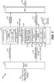
- a system that is operable to perform noise modulation and gain adjustment is shown and generally designated 100.
- the system 100 maybe integrated into an encoding system or apparatus (e.g., in a wireless telephone or coder/decoder (CODEC)).
- the system 100 is configured to encode a high-band portion of an input signal using mismatched frequencies. For example, a first component of the high-band portion in a first frequency range may be analyzed to generate filter coefficients for a synthesis filter, while a second component of the high-band portion in a different frequency range may be used to generate an excitation signal for the synthesis filter.
- the low-band signal 122 and the high-band signal 124 occupy non-overlapping frequency bands.
- the low-band signal 122 and the high-band signal 124 may occupy non-overlapping frequency bands of 50 Hz - 7 kHz and 7 kHz - 16 kHz, respectively.
- the low-band signal 122 and the high-band signal 124 may occupy non-overlapping frequency bands of 50 Hz - 8 kHz and 8 kHz - 16 kHz, respectively.
- the low-band signal 122 and the high-band signal 124 overlap (e.g., 50 Hz - 8 kHz and 7 kHz - 16 kHz), which may enable a low-pass filter and a high-pass filter of the analysis filter bank 110 to have a smooth rolloff, which may simplify design and reduce cost of the low-pass filter and the high-pass filter.
- Overlapping the low-band signal 122 and the high-band signal 124 may also enable smooth blending of low-band and high-band signals at a receiver, which may result in fewer audible artifacts.
- the input audio signal 102 may be a wideband (WB) signal having a frequency range of approximately 50 Hz to approximately 8 kHz.
- the low-band signal 122 may correspond to a frequency range of approximately 50 Hz to approximately 6.4 kHz
- the high-band signal 124 may correspond to a frequency range of approximately 6.4 kHz to approximately 8 kHz.
- the system 100 may include a low-band analysis module 130 configured to receive the low-band signal 122.
- the low-band analysis module 130 may represent a code excited linear prediction (CELP) encoder.
- the low-band analysis module 130 may include a LP analysis and coding module 132, a linear prediction coefficient (LPC) to line spectral pair (LSP) transform module 134, and a quantizer 136.
- LSPs may also be referred to as line spectral frequencies (LSFs), and the two terms may be used interchangeably herein.
- the LP analysis and coding module 132 may encode a spectral envelope of the low-band signal 122 as a set of LPCs.
- LPCs may be generated for each frame of audio (e.g., 20 ms of audio, corresponding to 320 samples at a sampling rate of 16 kHz), each sub-frame of audio (e.g., 5 ms of audio), or any combination thereof.
- the number of LPCs generated for each frame or sub-frame may be determined by the "order" of the LP analysis performed.
- the LP analysis and coding module 132 may generate a set of eleven LPCs corresponding to a tenth-order LP analysis.
- the LPC to LSP transform module 134 may transform the set of LPCs generated by the LP analysis and coding module 132 into a corresponding set of LSPs (e.g., using a one-to-one transform). Alternately, the set of LPCs may be one-to-one transformed into a corresponding set of parcor coefficients, log-area-ratio values, immittance spectral pairs (ISPs), or immittance spectral frequencies (ISFs).
- the transform between the set of LPCs and the set of LSPs maybe reversible without error.
- the quantizer 136 may quantize the set of LSPs generated by the transform module 134.
- the quantizer 136 may include or be coupled to multiple codebooks that include multiple entries (e.g., vectors).
- the quantizer 136 may identify entries of codebooks that are "closest to" (e.g., based on a distortion measure such as least squares or mean square error) the set of LSPs.
- the quantizer 136 may output an index value or series of index values corresponding to the location of the identified entries in the codebook.
- the output of the quantizer 136 may thus represent low-band filter parameters that are included in a low-band bit stream 142.
- the low-band analysis module 130 may also generate a low-band excitation signal 144.
- the low-band excitation signal 144 maybe an encoded signal that is generated by quantizing a LP residual signal that is generated during the LP process performed by the low-band analysis module 130.
- the LP residual signal may represent prediction error.
- the system 100 may further include a high-band analysis module 150 configured to receive the high-band signal 124 from the analysis filter bank 110 and the low-band excitation signal 144 from the low-band analysis module 130.
- the high-band analysis module 150 may generate high-band side information 172 based on the high-band signal 124 and the low-band excitation signal 144.
- the high-band side information 172 may include high-band LSPs and/or gain information (e.g., based on at least a ratio of high-band energy to low-band energy), as further described herein.
- the high-band analysis module 150 may include a high-band excitation generator 160.
- the high-band excitation generator 160 may generate a high-band excitation signal 161 by extending a spectrum of the low-band excitation signal 144 into the second high-band frequency range (e.g., 8 kHz - 16 kHz).
- the high-band excitation generator 160 may apply a transform to the low-band excitation signal (e.g., a non-linear transform such as an absolute-value or square operation) and may mix the transformed low-band excitation signal with a noise signal (e.g., white noise modulated according to an envelope corresponding to the low-band excitation signal 144 that mimics slow varying temporal characteristics of the low-band signal 122) to generate the high-band excitation signal 161.
- a transform e.g., a non-linear transform such as an absolute-value or square operation
- a noise signal e.g., white noise modulated according to an envelope corresponding to the low-band excitation signal 144 that mimics slow varying temporal characteristics of the low-band signal 122
- the LP analysis and coding module 152 may generate a set of LPCs that are transformed to LSPs by the transform module 154 and quantized by the quantizer 156 based on a codebook 163.
- the LP analysis and coding module 152, the transform module 154, and the quantizer 156 may use the high-band signal 124 to determine high-band filter information (e.g., high-band LSPs) that is included in the high-band side information 172.
- the high-band side information 172 may include high-band LSPs as well as high-band gain parameters.
- different signal models may be used for different kinds of audio data (e.g., speech, music, etc.), and the particular signal model that is in use may be negotiated by a transmitter and a receiver (or defined by an industry standard) prior to communication of encoded audio data.
- the high-band analysis module 150 at a transmitter may be able to generate the high-band side information 172 such that a corresponding high-band analysis module at a receiver is able to use the signal model to reconstruct the high-band signal 124 from the output bit stream 192.
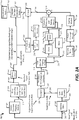
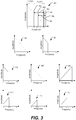
- FIG. 2A components used in an encoder 200 is shown, and graphs depicting frequency components of various signals that may represent signals of the encoder 200 are depicted in FIG. 3 .
- the encoder 200 may correspond to the system 100 of FIG. 1 .
- the input signal 201 may have frequency components such as illustrated in a graph 302 of FIG. 3 .
- the graphs in FIG. 3 are illustrative and some features may be emphasized for clarity.
- the graphs of FIG. 3 provide a simplified, non-limiting example according to one implementation to graphically illustrate simplified frequency spectrums of various signals that may be generated during encoding and/or decoding and are not necessarily drawn to scale.
- a low-band encoder 204 such as an ACELP encoder (e.g., the LP analysis and coding module 132 in the low-band analysis module 130 of FIG. 1 ), may encode the signal 203.
- the low-band encoder 204 may generate coding information, such as LPCs, and a low-band excitation signal 205.
- the low-band excitation signal 205 may have frequency components such as illustrated in the graph 304 of FIG. 3 .
- the band-pass signal 215 may be provided to the down-mixer 216, which may generate a signal 217 having an effective signal bandwidth extending from 0 Hz to (F2-F1) Hz, such as from 0 Hz to 8 kHz.
- the down-mixer 216 maybe configured to down-mix the band-pass signal 215 from the frequency range between 1.6 kHz and 9.6 kHz to baseband (e.g., a frequency range between 0 Hz and 8 kHz) to generate the signal 217.
- the down-mixer 216 may be implemented using two-stage Hilbert transforms.
- a switch 220 outputs one of the signals 217, 219 to be processed at an adaptive whitening and scaling module 222 according to the mode of operation, and an output of the adaptive whitening and scaling module is provided to a first input of a combiner 240, such as an adder.
- a second input of the combiner 240 receives a signal resulting from an output of a random noise generator 230 that has been processed according to a noise envelope module 232 (e.g., a modulator) and a scaling module 234.
- the combiner 240 generates a high-band excitation signal 241, such as the high-band excitation signal 161 of FIG. 1 .
- the input signal 201 that has an effective bandwidth in the frequency range between 0 Hz and F Hz may also be processed at a baseband signal generation path.
- the input signal 201 may be spectrally flipped at a second spectrum flipping module 242 to generate a flipped signal 243.
- the flipped signal 243 may be band-pass filtered at a filter 244 to generate a band-pass signal 245 having removed or reduced signal components outside the frequency range from (F-F2) Hz to (F-F1) Hz (e.g., from 1.6 kHz to 9.6 kHz).
- the LPCs may be used to configure a synthesis filter 260 that receives the high-band excitation signal 241 as an input and generates a synthesized high-band signal 261 as an output.
- the synthesized high-band signal 261 is compared to the high-band target signal 247 (e.g., energies of the signals 261 and 247 maybe compared at each sub-frame of the respective signals) at a temporal envelope estimation module 262 to generate gain information 263, such as gain shape parameter values.
- the gain information 263 is provided to a quantization module 264 to generate quantized gain information indices to be sent to the decoder, such as in the high-band side information 172 of FIG. 1 .
- the high-band excitation signal 241 generation path includes a downmix operation to generate the signal 217.
- This downmix operation can be complex if implemented through Hilbert transformers.
- An alternate implementation based on quadrature mirror filters (QMFs) can result in significantly higher overall system delays.
- the downmix operation is not included in high-band excitation signal 241 generation path. This may result in a mismatch between the high-band excitation signal 241 and the high-band target signal 247, as can be graphically visualized via comparison of the graph 312 to the graph 314 of FIG. 3 .
- generating the high-band excitation signal 241 according to the second mode may bypass the filter 214 (e.g., the pole-zero filter) and the down-mixer 216 and reduce complex and computationally expensive operations associated with pole-zero filtering and the down-mixer.
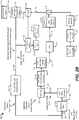
- the spectrum flipping operations, the band-pass filtering operations, and the down-mixing operations described with respect to the baseband signal generation path of FIG. 2A may be bypassed, and the spectral flip and synthesis module 292 of FIG. 2B may implicitly perform a synthesis operation to generate the baseband signal 247.
- the flipped signal 211 from the first spectrum flipping module 210 may be provided to the filter 218, and the filter 218 may filter the flipped signal 211 to generate the signal 219.
- the signal 219 may be provided to the input of the adaptive whitening and scaling module 222.
- Cost and design complexity of the encoder 200 of FIG. 2A may be reduced by implementing the techniques described herein using the encoder 290 of FIG. 2B (e.g., by removing the switches 212, 220, the filter 214, and the down-mixer 216 of FIG. 2A ).
- the low-band decoder 404 generates a synthesized low-band decoded signal 471.
- High-band signal synthesis includes providing the low-band excitation signal 205 of FIG. 2A (or a representation of the low-band excitation signal 205, such as a quantized version of the low-band excitation signal 205 received from an encoder) to the sampler 206 of FIG. 2A .
- High-band synthesis includes generating the high-band excitation signal 241 using the sampler 206, the non-linear transformation generator 208, the first spectrum flipping module 210, the filter 218, and the adaptive whitening and scaling module 222 to provide a first input to the combiner 240 of FIG. 2A .
- a second input to the combiner is generated by an output of the random noise generator 230 processed by the noise envelope module 232 and scaled at the scaling module 234 of FIG. 2A .
- High-band synthesis continues with processing by a mixer 464 configured to upmix the adjusted signal from the frequency range of 0 Hz to (F2-F1) Hz to the frequency range of (F-F2) Hz to (F-F1) Hz (e.g., 1.6 kHz to 9.6 kHz).
- An upmixed signal output by the mixer 464 is upsampled at a sampler 466, and an upsampled output of the sampler 466 is provided to a spectral flip module 468 that may operate as described with respect to the first spectrum flipping module 210 to generate a high-band decoded signal 469 that has a frequency band extending from F1 Hz to F2 Hz.
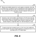
- a high-band excitation signal is generated based on the first data, at 604.
- the high-band excitation signal corresponds to a second component of the high-band portion of the audio signal.
- the second component has a second frequency range that differs from the first frequency range.
- the decoder may generate the high-band excitation signal without using a pole-zero filter and without using a down-mixing operation, such as by using the filter 218 of FIG. 4 (e.g., by bypassing or omitting the filter 214 and the down-mixer 216).
- the high-band excitation signal may correspond to the high-band excitation signal 241 of FIG. 4 .
- the high-band excitation signal is provided to a filter having filter coefficients generated based on the second data to generate a synthesized version of the high-band portion of the audio signal, at 606.
- the high-band excitation signal 241 of FIG. 4 is provided to the synthesis filter 260 of FIG. 4 , and the synthesis filter 260 of FIG. 4 may have filter coefficients that are generated based on the quantized LSP indices 461 received in the second data 403 of FIG. 4 .
- the method FIG. 6 may reduce complex and computationally expensive operations associated with the filter 214 and the down-mixer 216.
- speech and music CODEC 708 is illustrated as a component of the processors 710, in other implementations, one or more components of the speech and music CODEC 708 may be included in the processor 706, the CODEC 734, another processing component, or a combination thereof.
- the device 700 may include a memory 732 and a wireless controller 740 coupled to an antenna 742 via transceiver 750.
- the device 700 may include a display 728 coupled to a display controller 726.
- a speaker 748, a microphone 746, or both may be coupled to the CODEC 734.
- the CODEC 734 may include a digital-to-analog converter (DAC) 702 and an analog-to-digital converter (ADC) 704.
- DAC digital-to-analog converter
- ADC analog-to-digital converter
- the memory 732 may include instructions 756 executable by the processor 706, the processors 710, the CODEC 734, another processing unit of the device 700, or a combination thereof, to perform methods and processes disclosed herein, such as one or more of the methods of FIGS. 5-6 .
- One or more components of the systems of FIGS. 1 , 2A , 2B , or 4 may be implemented via dedicated hardware (e.g., circuitry), by a processor executing instructions to perform one or more tasks, or a combination thereof.
- the memory 732 or one or more components of the processor 706, the processors 710, and/or the CODEC 734 may be a memory device, such as a random access memory (RAM), magnetoresistive random access memory (MRAM), spin-torque transfer MRAM (STT-MRAM), flash memory, read-only memory (ROM), programmable read-only memory (PROM), erasable programmable read-only memory (EPROM), electrically erasable programmable read-only memory (EEPROM), registers, hard disk, a removable disk, or a compact disc read-only memory (CD-ROM).
- RAM random access memory
- MRAM magnetoresistive random access memory
- STT-MRAM spin-torque transfer MRAM
- ROM read-only memory
- PROM programmable read-only memory
- EPROM erasable programmable read-only memory
- EEPROM electrically erasable programmable read-only memory
- registers hard disk, a removable disk, or a compact disc read-only
- the memory device may include instructions (e.g., the instructions 756) that, when executed by a computer (e.g., a processor in the CODEC 734, the processor 706, and/or the processors 710), may cause the computer to perform at least a portion of one or more of the methods of FIGS. 5-6 .
- a computer e.g., a processor in the CODEC 734, the processor 706, and/or the processors 710
- the memory 732 or the one or more components of the processor 706, the processors 710, the CODEC 734 may be a non-transitory computer-readable medium that includes instructions (e.g., the instructions 756) that, when executed by a computer (e.g., a processor in the CODEC 734, the processor 706, and/or the processors 710), cause the computer perform at least a portion of one or more of the methods of FIGS. 5-6 .
- a computer e.g., a processor in the CODEC 734, the processor 706, and/or the processors 710
- the device 700 may be included in a system-in-package or system-on-chip device 722, such as a mobile station modem (MSM).
- MSM mobile station modem
- the processor 706, the processors 710, the display controller 726, the memory 732, the CODEC 734, the wireless controller 740, and the transceiver 750 are included in a system-in-package or the system-on-chip device 722.
- an input device 730 such as a touchscreen and/or keypad, and a power supply 744 are coupled to the system-on-chip device 722.
- the device 700 corresponds to a mobile communication device, a smartphone, a cellular phone, a laptop computer, a computer, a tablet computer, a PDA, a display device, a television, a gaming console, a music player, a radio, a digital video player, an optical disc player, a tuner, a camera, a navigation device, a decoder system, an encoder system, or any combination thereof.
- the processors 710 maybe operable to perform signal encoding and decoding operations in accordance with the described techniques.
- the microphone 746 may capture an audio signal.
- the ADC 704 may convert the captured audio signal from an analog waveform into a digital waveform that includes digital audio samples.
- the processors 710 may process the digital audio samples.
- the echo canceller 712 may reduce an echo that may have been created by an output of the speaker 748 entering the microphone 746.
- the vocoder encoder 736 may compress digital audio samples corresponding to a processed speech signal and may form a transmit packet (e.g. a representation of the compressed bits of the digital audio samples).
- the transmit packet may correspond to at least a portion of the bit stream 192 of FIG. 1 .
- the transmit packet may be stored in the memory 732.
- the transceiver 750 may modulate some form of the transmit packet (e.g., other information may be appended to the transmit packet) and may transmit the modulated data via the antenna 742.
- the antenna 742 may receive incoming packets that include a receive packet.
- the receive packet may be sent by another device via a network.
- the receive packet may correspond to at least a portion of the bit stream received at the ACELP core decoder 404 of FIG. 4 .
- the vocoder decoder 738 may decompress and decode the receive packet to generate reconstructed audio samples (e.g., corresponding to the synthesized audio signal 473).
- the echo canceller 712 may remove echo from the reconstructed audio samples.
- the DAC 702 may convert an output of the vocoder decoder 738 from a digital waveform to an analog waveform and may provide the converted waveform to the speaker 748 for output.
- a first apparatus includes means for generating a first signal corresponding to a first component of a high-band portion of an input audio signal.
- the first component may have a first frequency range.
- the means for generating the first signal may include the system 100 of FIG. 1 , the second spectrum flipping module 242 of FIG. 2A , the filter 244 of FIG. 2A , the down-mixer 246 of FIG. 2A , the spectral flip and synthesis module 292 of FIG. 2B , the vocoder encoder 736 of FIG. 7 , the processors 710 of FIG. 7 , the processor 706 of FIG. 7 , one or more additional processors configured to execute instructions, such as the instructions 756 of FIG. 7 , or a combination thereof.
- the first apparatus may also include means for generating a high-band excitation signal corresponding to a second component of the high-band portion of the audio signal.
- the second component may have a second frequency range that differs from the first frequency range.
- the means for generating the high-band excitation signal may include the high-band analysis module 150 of FIG. 1 , the analysis filter 202 of FIGS. 2A and 2B , the low-band encoder 204 of FIGS. 2A and 2B , the sampler 206 of FIGS. 2A and 2B , the non-linear transformation generator 208 of FIGS. 2A and 2B , the first spectrum flipping module 210 of FIGS. 2A and 2B , the filter 218 of FIGS.
- the adaptive whitening and scaling module 222 of FIGS. 2A and 2B the adaptive whitening and scaling module 222 of FIGS. 2A and 2B , the vocoder encoder 736 of FIG. 7 , the processors 710 of FIG. 7 , the processor 706 of FIG. 7 , one or more additional processors configured to execute instructions, such as the instructions 756 of FIG. 7 , or a combination thereof.
- the first apparatus may also include means for generating a synthesized version of the high-band portion of the audio signal.
- the means for generating the synthesized version may be configured to receive the high-band excitation signal and has filter coefficients generated based on the first signal.
- the means for generating the synthesized version may include the high-band analysis module 150 of FIG. 1 , the synthesis filter 260 of FIGS. 2A and 2B , the vocoder encoder 736 of FIG. 7 , the processors 710 of FIG. 7 , the processor 706 of FIG. 7 , one or more additional processors configured to execute instructions, such as the instructions 756 of FIG. 7 , or a combination thereof.
- a second apparatus may include means for generating a high-band excitation signal based on first data corresponding to a low-band portion of an audio signal.
- the audio signal may correspond to a received encoded audio signal that includes the first data and that further includes second data corresponding to a first component of a high-band portion of the audio signal.
- the first component may have a first frequency range.
- the high-band excitation signal may correspond to a second component of the high-band portion of the audio signal.
- the second component may have a second frequency range that differs from the first frequency range.
- the means for generating the high-band excitation signal may include the low-band encoder 404 of FIG. 4 , the sampler 206 of FIG.
- the non-linear transformation generator 208 of FIG. 4 the non-linear transformation generator 208 of FIG. 4 , the first spectrum flipping module 210 of FIG. 4 , the filter 218 of FIG. 4 , the adaptive whitening and scaling module 222 of FIG. 4 , the vocoder decoder 738 of FIG. 7 , the processors 710 of FIG. 7 , the processor 706 of FIG. 7 , one or more additional processors configured to execute instructions, such as the instructions 756 of FIG. 7 , or a combination thereof.
- the second apparatus may also include means for generating a synthesized version of the high-band portion of the audio signal.
- the means for generating the synthesized version may be configured to receive the high-band excitation signal and has filter coefficients generated based on the second data.
- the means for generating the synthesized version may include the synthesis filter bank 470 of FIG. 4 , the vocoder decoder 738 of FIG. 7 , the processors 710 of FIG. 7 , the processor 706 of FIG. 7 , one or more additional processors configured to execute instructions, such as the instructions 756 of FIG. 7 , or a combination thereof.
- the synthesis filter bank 470 may receive the high-band decoded signal 469. As described with respect to FIG.
- the high-band decoded signal 469 maybe generated using the second data 403 (e.g., the gain envelope data 463 and the quantized LSP indices 461).
- the decoder 400 of FIG. 4 may be included in the vocoder decoder 738 of FIG. 7 .
- components in the vocoder decoder 738 may operate in a substantially similar manner as the synthesis filter bank 470.
- one or more components in the vocoder decoder 738 may receive the high-band decoded signal 469 of FIG. 4 that is generated using the second data 403 (e.g., the gain envelope data 463 and the quantized LSP indices 461)
- a software module may reside in a memory device, such as RAM, MRAM, STT-MRAM, flash memory, ROM, PROM, EPROM, EEPROM, registers, hard disk, a removable disk, or a CD-ROM.
- An exemplary memory device is coupled to the processor such that the processor can read information from, and write information to, the memory device.
- the memory device may be integral to the processor.
- the processor and the storage medium may reside in an ASIC.
- the ASIC may reside in a computing device or a user terminal.
- the processor and the storage medium may reside as discrete components in a computing device or a user terminal.
Landscapes
- Engineering & Computer Science (AREA)
- Computational Linguistics (AREA)
- Signal Processing (AREA)
- Health & Medical Sciences (AREA)
- Audiology, Speech & Language Pathology (AREA)
- Human Computer Interaction (AREA)
- Physics & Mathematics (AREA)
- Acoustics & Sound (AREA)
- Multimedia (AREA)
- Quality & Reliability (AREA)
- Compression, Expansion, Code Conversion, And Decoders (AREA)
Applications Claiming Priority (3)
| Application Number | Priority Date | Filing Date | Title |
|---|---|---|---|
| US201462017753P | 2014-06-26 | 2014-06-26 | |
| US14/750,784 US9984699B2 (en) | 2014-06-26 | 2015-06-25 | High-band signal coding using mismatched frequency ranges |
| PCT/US2015/038120 WO2015200859A1 (en) | 2014-06-26 | 2015-06-26 | High-band signal coding using mismatched frequency ranges |
Publications (2)
| Publication Number | Publication Date |
|---|---|
| EP3161822A1 EP3161822A1 (en) | 2017-05-03 |
| EP3161822B1 true EP3161822B1 (en) | 2018-07-18 |
Family
ID=54931209
Family Applications (1)
| Application Number | Title | Priority Date | Filing Date |
|---|---|---|---|
| EP15734039.9A Active EP3161822B1 (en) | 2014-06-26 | 2015-06-26 | High-band signal coding using mismatched frequency ranges |
Country Status (9)
| Country | Link |
|---|---|
| US (1) | US9984699B2 (enExample) |
| EP (1) | EP3161822B1 (enExample) |
| JP (1) | JP6513718B2 (enExample) |
| KR (1) | KR101988710B1 (enExample) |
| CN (1) | CN106463135B (enExample) |
| CA (1) | CA2952286C (enExample) |
| ES (1) | ES2690096T3 (enExample) |
| HU (1) | HUE039699T2 (enExample) |
| WO (1) | WO2015200859A1 (enExample) |
Families Citing this family (9)
| Publication number | Priority date | Publication date | Assignee | Title |
|---|---|---|---|---|
| US9542955B2 (en) | 2014-03-31 | 2017-01-10 | Qualcomm Incorporated | High-band signal coding using multiple sub-bands |
| EP3067886A1 (en) | 2015-03-09 | 2016-09-14 | Fraunhofer-Gesellschaft zur Förderung der angewandten Forschung e.V. | Audio encoder for encoding a multichannel signal and audio decoder for decoding an encoded audio signal |
| US10109284B2 (en) * | 2016-02-12 | 2018-10-23 | Qualcomm Incorporated | Inter-channel encoding and decoding of multiple high-band audio signals |
| US10553222B2 (en) | 2017-03-09 | 2020-02-04 | Qualcomm Incorporated | Inter-channel bandwidth extension spectral mapping and adjustment |
| US10573326B2 (en) * | 2017-04-05 | 2020-02-25 | Qualcomm Incorporated | Inter-channel bandwidth extension |
| US10825467B2 (en) * | 2017-04-21 | 2020-11-03 | Qualcomm Incorporated | Non-harmonic speech detection and bandwidth extension in a multi-source environment |
| US20190051286A1 (en) * | 2017-08-14 | 2019-02-14 | Microsoft Technology Licensing, Llc | Normalization of high band signals in network telephony communications |
| EP4122217B1 (en) | 2020-03-20 | 2025-05-07 | Dolby International AB | Bass enhancement for loudspeakers |
| WO2022240442A1 (en) * | 2021-05-08 | 2022-11-17 | Cerence Operating Company | Noise reduction based on dynamic neural networks |
Family Cites Families (21)
| Publication number | Priority date | Publication date | Assignee | Title |
|---|---|---|---|---|
| SE9903553D0 (sv) * | 1999-01-27 | 1999-10-01 | Lars Liljeryd | Enhancing percepptual performance of SBR and related coding methods by adaptive noise addition (ANA) and noise substitution limiting (NSL) |
| JP4977471B2 (ja) * | 2004-11-05 | 2012-07-18 | パナソニック株式会社 | 符号化装置及び符号化方法 |
| UA94041C2 (ru) * | 2005-04-01 | 2011-04-11 | Квелкомм Инкорпорейтед | Способ и устройство для фильтрации, устраняющей разреженность |
| US8260611B2 (en) | 2005-04-01 | 2012-09-04 | Qualcomm Incorporated | Systems, methods, and apparatus for highband excitation generation |
| PT1875463T (pt) * | 2005-04-22 | 2019-01-24 | Qualcomm Inc | Sistemas, métodos e aparelho para nivelamento de fator de ganho |
| US9454974B2 (en) * | 2006-07-31 | 2016-09-27 | Qualcomm Incorporated | Systems, methods, and apparatus for gain factor limiting |
| KR101346358B1 (ko) * | 2006-09-18 | 2013-12-31 | 삼성전자주식회사 | 대역폭 확장 기법을 이용한 오디오 신호의 부호화/복호화방법 및 장치 |
| US20080267224A1 (en) | 2007-04-24 | 2008-10-30 | Rohit Kapoor | Method and apparatus for modifying playback timing of talkspurts within a sentence without affecting intelligibility |
| WO2010057680A1 (de) | 2008-11-21 | 2010-05-27 | Siemens Aktiengesellschaft | Verfahren und messeinrichtung zur ermittlung eines zustands eines elektrischen zünders eines gasturbinenbrenners sowie zündeinrichtung für einen gasturbinenbrenner |
| PL4231295T3 (pl) * | 2008-12-15 | 2024-05-06 | Fraunhofer-Gesellschaft zur Förderung der angewandten Forschung e.V. | Sposób dekodowania powiększania szerokości pasma audio oraz program komputerowy |
| US8352252B2 (en) | 2009-06-04 | 2013-01-08 | Qualcomm Incorporated | Systems and methods for preventing the loss of information within a speech frame |
| US8428938B2 (en) | 2009-06-04 | 2013-04-23 | Qualcomm Incorporated | Systems and methods for reconstructing an erased speech frame |
| US8600737B2 (en) * | 2010-06-01 | 2013-12-03 | Qualcomm Incorporated | Systems, methods, apparatus, and computer program products for wideband speech coding |
| US9047863B2 (en) | 2012-01-12 | 2015-06-02 | Qualcomm Incorporated | Systems, methods, apparatus, and computer-readable media for criticality threshold control |
| US9275644B2 (en) | 2012-01-20 | 2016-03-01 | Qualcomm Incorporated | Devices for redundant frame coding and decoding |
| US9620134B2 (en) | 2013-10-10 | 2017-04-11 | Qualcomm Incorporated | Gain shape estimation for improved tracking of high-band temporal characteristics |
| US10083708B2 (en) | 2013-10-11 | 2018-09-25 | Qualcomm Incorporated | Estimation of mixing factors to generate high-band excitation signal |
| US9384746B2 (en) | 2013-10-14 | 2016-07-05 | Qualcomm Incorporated | Systems and methods of energy-scaled signal processing |
| US10163447B2 (en) | 2013-12-16 | 2018-12-25 | Qualcomm Incorporated | High-band signal modeling |
| US9685164B2 (en) | 2014-03-31 | 2017-06-20 | Qualcomm Incorporated | Systems and methods of switching coding technologies at a device |
| US9697843B2 (en) | 2014-04-30 | 2017-07-04 | Qualcomm Incorporated | High band excitation signal generation |
-
2015
- 2015-06-25 US US14/750,784 patent/US9984699B2/en active Active
- 2015-06-26 WO PCT/US2015/038120 patent/WO2015200859A1/en not_active Ceased
- 2015-06-26 EP EP15734039.9A patent/EP3161822B1/en active Active
- 2015-06-26 ES ES15734039.9T patent/ES2690096T3/es active Active
- 2015-06-26 CN CN201580033935.2A patent/CN106463135B/zh active Active
- 2015-06-26 JP JP2016575154A patent/JP6513718B2/ja active Active
- 2015-06-26 KR KR1020167036229A patent/KR101988710B1/ko active Active
- 2015-06-26 HU HUE15734039A patent/HUE039699T2/hu unknown
- 2015-06-26 CA CA2952286A patent/CA2952286C/en active Active
Non-Patent Citations (1)
| Title |
|---|
| None * |
Also Published As
| Publication number | Publication date |
|---|---|
| CA2952286A1 (en) | 2015-12-30 |
| WO2015200859A1 (en) | 2015-12-30 |
| US9984699B2 (en) | 2018-05-29 |
| CA2952286C (en) | 2019-07-02 |
| JP6513718B2 (ja) | 2019-05-15 |
| CN106463135A (zh) | 2017-02-22 |
| EP3161822A1 (en) | 2017-05-03 |
| ES2690096T3 (es) | 2018-11-19 |
| HUE039699T2 (hu) | 2019-01-28 |
| CN106463135B (zh) | 2019-11-12 |
| US20150380008A1 (en) | 2015-12-31 |
| KR101988710B1 (ko) | 2019-06-12 |
| KR20170026382A (ko) | 2017-03-08 |
| JP2017523461A (ja) | 2017-08-17 |
Similar Documents
| Publication | Publication Date | Title |
|---|---|---|
| EP3161825B1 (en) | Temporal gain adjustment based on high-band signal characteristic | |
| EP3161822B1 (en) | High-band signal coding using mismatched frequency ranges | |
| US9818419B2 (en) | High-band signal coding using multiple sub-bands | |
| BR112016030386B1 (pt) | Codificação de sinal de banda alta com o uso de faixas de frequência incompatíveis |
Legal Events
| Date | Code | Title | Description |
|---|---|---|---|
| STAA | Information on the status of an ep patent application or granted ep patent |
Free format text: STATUS: THE INTERNATIONAL PUBLICATION HAS BEEN MADE |
|
| PUAI | Public reference made under article 153(3) epc to a published international application that has entered the european phase |
Free format text: ORIGINAL CODE: 0009012 |
|
| STAA | Information on the status of an ep patent application or granted ep patent |
Free format text: STATUS: REQUEST FOR EXAMINATION WAS MADE |
|
| 17P | Request for examination filed |
Effective date: 20161207 |
|
| AK | Designated contracting states |
Kind code of ref document: A1 Designated state(s): AL AT BE BG CH CY CZ DE DK EE ES FI FR GB GR HR HU IE IS IT LI LT LU LV MC MK MT NL NO PL PT RO RS SE SI SK SM TR |
|
| AX | Request for extension of the european patent |
Extension state: BA ME |
|
| DAV | Request for validation of the european patent (deleted) | ||
| DAX | Request for extension of the european patent (deleted) | ||
| GRAP | Despatch of communication of intention to grant a patent |
Free format text: ORIGINAL CODE: EPIDOSNIGR1 |
|
| STAA | Information on the status of an ep patent application or granted ep patent |
Free format text: STATUS: GRANT OF PATENT IS INTENDED |
|
| INTG | Intention to grant announced |
Effective date: 20180125 |
|
| GRAS | Grant fee paid |
Free format text: ORIGINAL CODE: EPIDOSNIGR3 |
|
| GRAA | (expected) grant |
Free format text: ORIGINAL CODE: 0009210 |
|
| STAA | Information on the status of an ep patent application or granted ep patent |
Free format text: STATUS: THE PATENT HAS BEEN GRANTED |
|
| AK | Designated contracting states |
Kind code of ref document: B1 Designated state(s): AL AT BE BG CH CY CZ DE DK EE ES FI FR GB GR HR HU IE IS IT LI LT LU LV MC MK MT NL NO PL PT RO RS SE SI SK SM TR |
|
| REG | Reference to a national code |
Ref country code: GB Ref legal event code: FG4D |
|
| REG | Reference to a national code |
Ref country code: CH Ref legal event code: EP |
|
| REG | Reference to a national code |
Ref country code: IE Ref legal event code: FG4D |
|
| REG | Reference to a national code |
Ref country code: AT Ref legal event code: REF Ref document number: 1020210 Country of ref document: AT Kind code of ref document: T Effective date: 20180815 |
|
| REG | Reference to a national code |
Ref country code: DE Ref legal event code: R096 Ref document number: 602015013752 Country of ref document: DE |
|
| REG | Reference to a national code |
Ref country code: NL Ref legal event code: FP |
|
| REG | Reference to a national code |
Ref country code: ES Ref legal event code: FG2A Ref document number: 2690096 Country of ref document: ES Kind code of ref document: T3 Effective date: 20181119 |
|
| REG | Reference to a national code |
Ref country code: LT Ref legal event code: MG4D |
|
| REG | Reference to a national code |
Ref country code: AT Ref legal event code: MK05 Ref document number: 1020210 Country of ref document: AT Kind code of ref document: T Effective date: 20180718 |
|
| REG | Reference to a national code |
Ref country code: HU Ref legal event code: AG4A Ref document number: E039699 Country of ref document: HU |
|
| PG25 | Lapsed in a contracting state [announced via postgrant information from national office to epo] |
Ref country code: NO Free format text: LAPSE BECAUSE OF FAILURE TO SUBMIT A TRANSLATION OF THE DESCRIPTION OR TO PAY THE FEE WITHIN THE PRESCRIBED TIME-LIMIT Effective date: 20181018 Ref country code: GR Free format text: LAPSE BECAUSE OF FAILURE TO SUBMIT A TRANSLATION OF THE DESCRIPTION OR TO PAY THE FEE WITHIN THE PRESCRIBED TIME-LIMIT Effective date: 20181019 Ref country code: SE Free format text: LAPSE BECAUSE OF FAILURE TO SUBMIT A TRANSLATION OF THE DESCRIPTION OR TO PAY THE FEE WITHIN THE PRESCRIBED TIME-LIMIT Effective date: 20180718 Ref country code: RS Free format text: LAPSE BECAUSE OF FAILURE TO SUBMIT A TRANSLATION OF THE DESCRIPTION OR TO PAY THE FEE WITHIN THE PRESCRIBED TIME-LIMIT Effective date: 20180718 Ref country code: LT Free format text: LAPSE BECAUSE OF FAILURE TO SUBMIT A TRANSLATION OF THE DESCRIPTION OR TO PAY THE FEE WITHIN THE PRESCRIBED TIME-LIMIT Effective date: 20180718 Ref country code: AT Free format text: LAPSE BECAUSE OF FAILURE TO SUBMIT A TRANSLATION OF THE DESCRIPTION OR TO PAY THE FEE WITHIN THE PRESCRIBED TIME-LIMIT Effective date: 20180718 Ref country code: IS Free format text: LAPSE BECAUSE OF FAILURE TO SUBMIT A TRANSLATION OF THE DESCRIPTION OR TO PAY THE FEE WITHIN THE PRESCRIBED TIME-LIMIT Effective date: 20181118 Ref country code: PL Free format text: LAPSE BECAUSE OF FAILURE TO SUBMIT A TRANSLATION OF THE DESCRIPTION OR TO PAY THE FEE WITHIN THE PRESCRIBED TIME-LIMIT Effective date: 20180718 Ref country code: BG Free format text: LAPSE BECAUSE OF FAILURE TO SUBMIT A TRANSLATION OF THE DESCRIPTION OR TO PAY THE FEE WITHIN THE PRESCRIBED TIME-LIMIT Effective date: 20181018 |
|
| PG25 | Lapsed in a contracting state [announced via postgrant information from national office to epo] |
Ref country code: AL Free format text: LAPSE BECAUSE OF FAILURE TO SUBMIT A TRANSLATION OF THE DESCRIPTION OR TO PAY THE FEE WITHIN THE PRESCRIBED TIME-LIMIT Effective date: 20180718 Ref country code: LV Free format text: LAPSE BECAUSE OF FAILURE TO SUBMIT A TRANSLATION OF THE DESCRIPTION OR TO PAY THE FEE WITHIN THE PRESCRIBED TIME-LIMIT Effective date: 20180718 Ref country code: HR Free format text: LAPSE BECAUSE OF FAILURE TO SUBMIT A TRANSLATION OF THE DESCRIPTION OR TO PAY THE FEE WITHIN THE PRESCRIBED TIME-LIMIT Effective date: 20180718 |
|
| REG | Reference to a national code |
Ref country code: DE Ref legal event code: R097 Ref document number: 602015013752 Country of ref document: DE |
|
| PG25 | Lapsed in a contracting state [announced via postgrant information from national office to epo] |
Ref country code: EE Free format text: LAPSE BECAUSE OF FAILURE TO SUBMIT A TRANSLATION OF THE DESCRIPTION OR TO PAY THE FEE WITHIN THE PRESCRIBED TIME-LIMIT Effective date: 20180718 Ref country code: RO Free format text: LAPSE BECAUSE OF FAILURE TO SUBMIT A TRANSLATION OF THE DESCRIPTION OR TO PAY THE FEE WITHIN THE PRESCRIBED TIME-LIMIT Effective date: 20180718 Ref country code: CZ Free format text: LAPSE BECAUSE OF FAILURE TO SUBMIT A TRANSLATION OF THE DESCRIPTION OR TO PAY THE FEE WITHIN THE PRESCRIBED TIME-LIMIT Effective date: 20180718 |
|
| PLBE | No opposition filed within time limit |
Free format text: ORIGINAL CODE: 0009261 |
|
| STAA | Information on the status of an ep patent application or granted ep patent |
Free format text: STATUS: NO OPPOSITION FILED WITHIN TIME LIMIT |
|
| PG25 | Lapsed in a contracting state [announced via postgrant information from national office to epo] |
Ref country code: SM Free format text: LAPSE BECAUSE OF FAILURE TO SUBMIT A TRANSLATION OF THE DESCRIPTION OR TO PAY THE FEE WITHIN THE PRESCRIBED TIME-LIMIT Effective date: 20180718 Ref country code: DK Free format text: LAPSE BECAUSE OF FAILURE TO SUBMIT A TRANSLATION OF THE DESCRIPTION OR TO PAY THE FEE WITHIN THE PRESCRIBED TIME-LIMIT Effective date: 20180718 Ref country code: SK Free format text: LAPSE BECAUSE OF FAILURE TO SUBMIT A TRANSLATION OF THE DESCRIPTION OR TO PAY THE FEE WITHIN THE PRESCRIBED TIME-LIMIT Effective date: 20180718 |
|
| 26N | No opposition filed |
Effective date: 20190423 |
|
| PG25 | Lapsed in a contracting state [announced via postgrant information from national office to epo] |
Ref country code: SI Free format text: LAPSE BECAUSE OF FAILURE TO SUBMIT A TRANSLATION OF THE DESCRIPTION OR TO PAY THE FEE WITHIN THE PRESCRIBED TIME-LIMIT Effective date: 20180718 |
|
| PG25 | Lapsed in a contracting state [announced via postgrant information from national office to epo] |
Ref country code: MC Free format text: LAPSE BECAUSE OF FAILURE TO SUBMIT A TRANSLATION OF THE DESCRIPTION OR TO PAY THE FEE WITHIN THE PRESCRIBED TIME-LIMIT Effective date: 20180718 |
|
| REG | Reference to a national code |
Ref country code: CH Ref legal event code: PL |
|
| REG | Reference to a national code |
Ref country code: BE Ref legal event code: MM Effective date: 20190630 |
|
| PG25 | Lapsed in a contracting state [announced via postgrant information from national office to epo] |
Ref country code: TR Free format text: LAPSE BECAUSE OF FAILURE TO SUBMIT A TRANSLATION OF THE DESCRIPTION OR TO PAY THE FEE WITHIN THE PRESCRIBED TIME-LIMIT Effective date: 20180718 |
|
| PG25 | Lapsed in a contracting state [announced via postgrant information from national office to epo] |
Ref country code: IE Free format text: LAPSE BECAUSE OF NON-PAYMENT OF DUE FEES Effective date: 20190626 |
|
| PG25 | Lapsed in a contracting state [announced via postgrant information from national office to epo] |
Ref country code: BE Free format text: LAPSE BECAUSE OF NON-PAYMENT OF DUE FEES Effective date: 20190630 Ref country code: LU Free format text: LAPSE BECAUSE OF NON-PAYMENT OF DUE FEES Effective date: 20190626 Ref country code: LI Free format text: LAPSE BECAUSE OF NON-PAYMENT OF DUE FEES Effective date: 20190630 Ref country code: CH Free format text: LAPSE BECAUSE OF NON-PAYMENT OF DUE FEES Effective date: 20190630 |
|
| PG25 | Lapsed in a contracting state [announced via postgrant information from national office to epo] |
Ref country code: PT Free format text: LAPSE BECAUSE OF FAILURE TO SUBMIT A TRANSLATION OF THE DESCRIPTION OR TO PAY THE FEE WITHIN THE PRESCRIBED TIME-LIMIT Effective date: 20181118 |
|
| PG25 | Lapsed in a contracting state [announced via postgrant information from national office to epo] |
Ref country code: CY Free format text: LAPSE BECAUSE OF FAILURE TO SUBMIT A TRANSLATION OF THE DESCRIPTION OR TO PAY THE FEE WITHIN THE PRESCRIBED TIME-LIMIT Effective date: 20180718 |
|
| PG25 | Lapsed in a contracting state [announced via postgrant information from national office to epo] |
Ref country code: MT Free format text: LAPSE BECAUSE OF FAILURE TO SUBMIT A TRANSLATION OF THE DESCRIPTION OR TO PAY THE FEE WITHIN THE PRESCRIBED TIME-LIMIT Effective date: 20180718 |
|
| PG25 | Lapsed in a contracting state [announced via postgrant information from national office to epo] |
Ref country code: MK Free format text: LAPSE BECAUSE OF FAILURE TO SUBMIT A TRANSLATION OF THE DESCRIPTION OR TO PAY THE FEE WITHIN THE PRESCRIBED TIME-LIMIT Effective date: 20180718 |
|
| PGFP | Annual fee paid to national office [announced via postgrant information from national office to epo] |
Ref country code: NL Payment date: 20250515 Year of fee payment: 11 |
|
| PGFP | Annual fee paid to national office [announced via postgrant information from national office to epo] |
Ref country code: FI Payment date: 20250527 Year of fee payment: 11 |
|
| PGFP | Annual fee paid to national office [announced via postgrant information from national office to epo] |
Ref country code: DE Payment date: 20250509 Year of fee payment: 11 |
|
| PGFP | Annual fee paid to national office [announced via postgrant information from national office to epo] |
Ref country code: GB Payment date: 20250508 Year of fee payment: 11 |
|
| PGFP | Annual fee paid to national office [announced via postgrant information from national office to epo] |
Ref country code: HU Payment date: 20250605 Year of fee payment: 11 Ref country code: FR Payment date: 20250512 Year of fee payment: 11 |
|
| PGFP | Annual fee paid to national office [announced via postgrant information from national office to epo] |
Ref country code: ES Payment date: 20250709 Year of fee payment: 11 |
|
| PGFP | Annual fee paid to national office [announced via postgrant information from national office to epo] |
Ref country code: IT Payment date: 20250610 Year of fee payment: 11 |