EP3160142A1 - Procédé de codage et procédé de décodage d'une image basée sur un champ de lumière et dispositifs correspondants - Google Patents
Procédé de codage et procédé de décodage d'une image basée sur un champ de lumière et dispositifs correspondants Download PDFInfo
- Publication number
- EP3160142A1 EP3160142A1 EP15306685.7A EP15306685A EP3160142A1 EP 3160142 A1 EP3160142 A1 EP 3160142A1 EP 15306685 A EP15306685 A EP 15306685A EP 3160142 A1 EP3160142 A1 EP 3160142A1
- Authority
- EP
- European Patent Office
- Prior art keywords
- block
- blocks
- spatial
- prediction
- immediately surrounding
- Prior art date
- Legal status (The legal status is an assumption and is not a legal conclusion. Google has not performed a legal analysis and makes no representation as to the accuracy of the status listed.)
- Withdrawn
Links
Images


Classifications
-
- H—ELECTRICITY
- H04—ELECTRIC COMMUNICATION TECHNIQUE
- H04N—PICTORIAL COMMUNICATION, e.g. TELEVISION
- H04N19/00—Methods or arrangements for coding, decoding, compressing or decompressing digital video signals
- H04N19/50—Methods or arrangements for coding, decoding, compressing or decompressing digital video signals using predictive coding
- H04N19/597—Methods or arrangements for coding, decoding, compressing or decompressing digital video signals using predictive coding specially adapted for multi-view video sequence encoding
-
- H—ELECTRICITY
- H04—ELECTRIC COMMUNICATION TECHNIQUE
- H04N—PICTORIAL COMMUNICATION, e.g. TELEVISION
- H04N19/00—Methods or arrangements for coding, decoding, compressing or decompressing digital video signals
- H04N19/10—Methods or arrangements for coding, decoding, compressing or decompressing digital video signals using adaptive coding
- H04N19/134—Methods or arrangements for coding, decoding, compressing or decompressing digital video signals using adaptive coding characterised by the element, parameter or criterion affecting or controlling the adaptive coding
- H04N19/167—Position within a video image, e.g. region of interest [ROI]
-
- H—ELECTRICITY
- H04—ELECTRIC COMMUNICATION TECHNIQUE
- H04N—PICTORIAL COMMUNICATION, e.g. TELEVISION
- H04N19/00—Methods or arrangements for coding, decoding, compressing or decompressing digital video signals
- H04N19/10—Methods or arrangements for coding, decoding, compressing or decompressing digital video signals using adaptive coding
- H04N19/169—Methods or arrangements for coding, decoding, compressing or decompressing digital video signals using adaptive coding characterised by the coding unit, i.e. the structural portion or semantic portion of the video signal being the object or the subject of the adaptive coding
- H04N19/17—Methods or arrangements for coding, decoding, compressing or decompressing digital video signals using adaptive coding characterised by the coding unit, i.e. the structural portion or semantic portion of the video signal being the object or the subject of the adaptive coding the unit being an image region, e.g. an object
- H04N19/176—Methods or arrangements for coding, decoding, compressing or decompressing digital video signals using adaptive coding characterised by the coding unit, i.e. the structural portion or semantic portion of the video signal being the object or the subject of the adaptive coding the unit being an image region, e.g. an object the region being a block, e.g. a macroblock
-
- H—ELECTRICITY
- H04—ELECTRIC COMMUNICATION TECHNIQUE
- H04N—PICTORIAL COMMUNICATION, e.g. TELEVISION
- H04N19/00—Methods or arrangements for coding, decoding, compressing or decompressing digital video signals
- H04N19/50—Methods or arrangements for coding, decoding, compressing or decompressing digital video signals using predictive coding
- H04N19/503—Methods or arrangements for coding, decoding, compressing or decompressing digital video signals using predictive coding involving temporal prediction
- H04N19/51—Motion estimation or motion compensation
- H04N19/577—Motion compensation with bidirectional frame interpolation, i.e. using B-pictures
-
- H—ELECTRICITY
- H04—ELECTRIC COMMUNICATION TECHNIQUE
- H04N—PICTORIAL COMMUNICATION, e.g. TELEVISION
- H04N19/00—Methods or arrangements for coding, decoding, compressing or decompressing digital video signals
- H04N19/50—Methods or arrangements for coding, decoding, compressing or decompressing digital video signals using predictive coding
- H04N19/593—Methods or arrangements for coding, decoding, compressing or decompressing digital video signals using predictive coding involving spatial prediction techniques
-
- H—ELECTRICITY
- H04—ELECTRIC COMMUNICATION TECHNIQUE
- H04N—PICTORIAL COMMUNICATION, e.g. TELEVISION
- H04N19/00—Methods or arrangements for coding, decoding, compressing or decompressing digital video signals
- H04N19/10—Methods or arrangements for coding, decoding, compressing or decompressing digital video signals using adaptive coding
- H04N19/102—Methods or arrangements for coding, decoding, compressing or decompressing digital video signals using adaptive coding characterised by the element, parameter or selection affected or controlled by the adaptive coding
- H04N19/103—Selection of coding mode or of prediction mode
- H04N19/11—Selection of coding mode or of prediction mode among a plurality of spatial predictive coding modes
Definitions
- the present disclosure relates to light field imaging, and to technologies for acquiring and processing light field data. More precisely, a method and a device for encoding and a method and a device for decoding a light field based image, namely a plenoptic image, are disclosed.
- Plenoptic cameras are gaining a lot of popularity in the field of computational photography because of the additional information they capture compared to traditional cameras. Indeed, they are able to measure the amount of light traveling along each ray bundle that intersects the sensor, thanks to a microlens array placed between a main lens and a sensor. As a result, such cameras have novel post-capture processing capabilities. For example, after the image acquisition, the point of view, the focus or the depth of field may be modified.
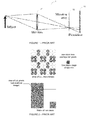
- a schematic view of a plenoptic camera is represented on Figure 1 .
- the plenoptic camera 1 is formed of a lens arrangement associated with a photosensor array 13, also called imaging sensor.
- the lens arrangement comprises a main lens 11 and a microlens array 12, which comprises a plurality of microlenses (e.g. an array of LxL microlenses).
- a micro-image is an nxn image formed on the photosensor 13 array behind a microlens.
- the collection of micro-images forms a raw plenoptic image, more simply called a raw image. From the raw image, a matrix of views (also called light-field content) may be obtained by demosaicing and demultiplexing.
- the demosaicing enables to recover a full color raw image, i.e. to recover full color information (for example RGB information, RGB standing for "Red”, “Green” and “Blue”) for the pixels of the raw image.
- the demultiplexing performed after the demosaicing enables to recover the different views.
- Demultiplexing comprises grouping co-located pixels from every micro-image after demosaicing. A view is also called a sub-aperture image.
- Some cameras such as the Pelican Imaging® camera, directly deliver matrices of views (i.e. does not require de-mozaicing).
- the microlens array is an array of LxL micro-lenses and each micro-image is of size nxn
- the matrix of views obtained after demosaicing and de-multiplexing is of size nxn with each sub-aperture image/view being of size LxL.
- Encoding such content i.e. the raw image or the matrix of views
- video codecs e.g. H.264, HEVC, etc
- a method for encoding a plenoptic image divided into blocks comprises:
- the present embodiments also provide a device for encoding a plenoptic image divided into blocks.
- the device for encoding comprises:
- the present embodiments also provide a non-transitory computer readable medium with instructions stored therein which, upon execution, instruct at least one processor to:
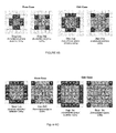
- predictively encoding immediately surrounding blocks by spatially interleaving spatial unidirectional prediction and spatial bi-directional prediction may comprise encoding the immediately surrounding blocks neighboring vertically or horizontally the central block by spatial unidirectional prediction and encoding the other surrounding blocks by spatial bi-directional prediction.
- predictively encoding immediately surrounding blocks by spatially interleaving spatial unidirectional prediction and spatial bi-directional prediction may comprise encoding one immediately surrounding block neighboring vertically the central block and one immediately surrounding block neighboring horizontally the central block spatial by unidirectional prediction; encoding the immediately surrounding block neighboring the two immediately surrounding blocks previously encoded by bi-directional prediction; encoding, by unidirectional prediction, the immediately surrounding blocks neighboring vertically or horizontally one of the previously encoded blocks and encoding the remaining immediately surrounding block by bi-directional prediction.
- remaining blocks are predictively encoded from the center of the plenoptic image up to the borders of the plenoptic image by spatially interleaving spatial unidirectional and spatial bi-directional predictions.
- the blocks are one of a micro-image or a view.
- the central is intra coded without spatial prediction.
- the central block is temporally predicted from a spatially co-located block in a reconstructed plenoptic image.
- the blocks are views and during prediction of a block by a reference block, the reference block is weighted by a weight derived from vignetting information.
- a method for decoding a plenoptic image divided into blocks comprises:
- the present embodiments also provide a device for decoding a plenoptic image divided into blocks.
- the device for decoding comprises:
- the present embodiments also provide a non-transitory computer readable medium with instructions stored therein which, upon execution, instruct at least one processor to:
- predictively decoding immediately surrounding blocks by spatially interleaving spatial unidirectional prediction and spatial bi-directional prediction may comprise decoding the immediately surrounding blocks neighboring vertically or horizontally the central block by spatial unidirectional prediction and decoding the other surrounding blocks by spatial bi-directional prediction.
- predictively decoding immediately surrounding blocks by spatially interleaving spatial unidirectional prediction and spatial bi-directional prediction may comprise decoding one immediately surrounding block neighboring vertically the central block and one immediately surrounding block neighboring horizontally the central block spatial by unidirectional prediction; decoding the immediately surrounding block neighboring the two immediately surrounding blocks previously decoded by bi-directional prediction; decoding, by unidirectional prediction, the immediately surrounding blocks neighboring vertically or horizontally one of the previously decoded blocks and decoding the remaining immediately surrounding block by bi-directional prediction.
- remaining blocks are predictively decoded from the center of the plenoptic image up to the borders of the plenoptic image by interleaving spatial unidirectional and spatial bi-directional predictions
- the blocks are one of a micro-image or a view.
- the central block is intra coded without spatial prediction.
- the central block is temporally predicted from a spatially co-located block in a reconstructed plenoptic image.
- the blocks are views and during prediction of a block by a reference block, the reference block is weighted by a weight derived from vignetting information.
- Figure 3 represents an exemplary architecture of a transmitter 100 configured to encode a plenoptic image in a stream according to an exemplary and non-limiting embodiment.
- the transmitter 100 comprises one or more processor(s) 1000, which could comprise, for example, a CPU, a GPU and/or a DSP (English acronym of Digital Signal Processor), along with internal memory 1030 (e.g. RAM, ROM, and/or EPROM).
- the transmitter 100 comprises one or more communication interface(s) 1010, each adapted to display output information and/or allow a user to enter commands and/or data (e.g. a keyboard, a mouse, a touchpad, a webcam); and a power source 1020 which may be external to the transmitter 100.
- the transmitter 100 may also comprise one or more network interface(s) (not shown).
- Encoder module 1040 represents a module that may be included in a device to perform the coding functions. Additionally, encoder module 1040 may be implemented as a separate element of the transmitter 100 or may be incorporated within processor(s) 1000 as a combination of hardware and software as known to those skilled in the art.
- the plenoptic image may be obtained from a source.
- the source can be, but is not limited to:
- the stream may be sent to a destination.
- the stream is stored in a remote or in a local memory, e.g. a video memory or a RAM, a hard disk.
- the stream is sent to a storage interface, e.g. an interface with a mass storage, a ROM, a flash memory, an optical disc or a magnetic support and/or transmitted over a communication interface, e.g. an interface to a point to point link, a communication bus, a point to multipoint link or a broadcast network.
- the transmitter 100 further comprises a computer program stored in the memory 1030.
- the computer program comprises instructions which, when executed by the transmitter 100, in particular by the processor 1000, enable the transmitter 100 to execute the method described with reference to figure 4 .
- the computer program is stored externally to the transmitter 100 on a non-transitory digital data support, e.g. on an external storage medium such as a HDD, CD-ROM, DVD, a read-only and/or DVD drive and/or a DVD Read/Write drive, all known in the art.
- the transmitter 100 thus comprises a mechanism to read the computer program. Further, the transmitter 100 could access one or more Universal Serial Bus (USB)-type storage devices (e.g., "memory sticks.") through corresponding USB ports (not shown).
- USB Universal Serial Bus
- the transmitter 100 can be, but is not limited to:
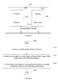
- Figure 4 represents a flowchart of a method for encoding a plenoptic image in a stream according to a specific and non-limiting embodiment.
- the method starts at step S100.
- a step S110 a transmitter accesses a current plenoptic image divided into blocks.
- a block is a view.
- a block is a micro-image.
- Block size may be either read from metadata, or determined from the content. Block size may also be transmitted in the stream, if not deducible from another information available at decoder side (e.g. camera device model).
- the transmitter encodes a central block of the current plenoptic image without spatial prediction, i.e. without reference to another block in the same image.
- a central block is a block located in a central region of the current plenoptic image.
- the central block is located at the center of the current plenoptic image to be encoded.
- the central block may be encoded in intra mode without spatial prediction.
- the central block is thus coded using information contained only in this block.
- the central block is coded in IPCM mode (IPCM stands for Intra Pulse Code Modulation ), the pixel values of the block are coded directly without prediction, transformation or quantization which are bypassed.
- the central block is thus coded without any loss of fidelity.
- the central block is coded with prediction from a constant block, e.g. for example from a block whose pixels are all equal to 128.
- Residues are thus obtained by subtracting the constant block from the central block.
- the residues are then transformed, quantized and entropy coded.
- the central block is temporally predicted from a spatially co-located block in a reconstructed plenoptic image, i.e. a plenoptic image already coded and reconstructed for prediction and stored in a DPB (DPB stands for Decoded Picture Buffer).
- DPB Decoded Picture Buffer
- the spatially co-located block is thus a block whose spatial position in the reconstructed plenoptic image is the same as the spatial position of the central block in the current plenoptic image. Residues are thus obtained by subtracting the co-located block from the central block.
- the central block may be the block of coordinates ⁇ n - 1 2 ⁇ , ⁇ n - 1 2 ⁇ where ⁇ . ⁇ denotes the integer part.
- the transmitter predictively encodes the remaining blocks from the center of the current plenoptic image up to the borders of the current plenoptic image by spatially interleaving spatial unidirectional and spatial bi-directional predictions.
- the transmitter predictively encodes the blocks immediately surrounding the central block by spatially interleaving spatial unidirectional prediction and spatial bi-directional prediction.
- Unidirectional prediction specifically horizontal and vertical predictions
- bi-directional prediction sub-steps are interleaved in order to propagate information from the center to the borders of the array/matrix.
- Figures 6A to 6C show the spatial interleaving of unidirectional and bi-directional predictions in the case where n is even (left side) and in the case where n is odd (right side). The method ends at S140.
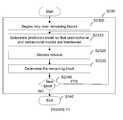
- Step S130 is detailed on figure 7 .
- the methods begins to loop over the remaining blocks, i.e. the blocks different from the central block already coded at step S120.
- the remaining blocks are for example stored in a memory of the transmitter.
- a prediction mode between unidirectional and bidirectional is determined for the block to be coded.
- the prediction mode is determined so that spatial unidirectional and spatial bi-directional predictions are interleaved.
- Prediction modes and coding order are either known at decoder side as default parameters, e.g. defined by a standard, or are explicitly transmitted in the stream, e.g. encoded in the stream.
- P 0 and B 0 are empty sets.
- the blocks to be encoded during a step k, k ⁇ 1, are the following:
- Residues ⁇ are determined by subtracting a reference block R (pixel by pixel) from the block C to be encoded to form a residual block ⁇ [ i,j ] .
- ⁇ [ i,j ] C [ i,j ] - R [ i , j ] .
- R [ i , j ] may be an average of 2 blocks.
- the residual block also called block of residues is encoded.
- Encoding the residual block usually comprises transforming (e.g. using a DCT) the residual block into coefficients, quantizing the coefficients and entropy coding the quantized coefficients. It will be appreciated, however, that the present principles are not restricted to this specific encoding method.
- the transmitter checks whether more remaining blocks exists. If yes, the control returns to step S1310. Otherwise, the method ends at S140.
- the disparity between neighboring blocks is taken into account when determining the residues.
- the disparity has only one component: shifts between horizontal neighbors are horizontal only and shifts between vertical neighbors are vertical only.
- There is a direct relationship between depth and disparity. Specifically, disp (b*f)/depth, where b is the distance between two viewpoints and f is the focal length. Therefore, disparity may be derived from depth estimations using other metadata delivered along with plenoptic material (focal length and micro-centers position for micro-images, or with virtual inter-axial distances for a matrix of views).
- Depth estimations may be determined from a depth map delivered along with plenoptic material (one value per pixel or per block, depending on depth resolution). In a variant, depth may be inferred (e.g. one value for the whole image, by reading metadata encoding the focus distance).
- disparities may be determined (one value per pixel or preferably one value per block) directly from the content, in which case, values have to be transmitted along with the stream.
- step S1320 illustrates the vignetting effect is further taken into account when determining the residues.
- Figure 8 depicts a matrix of views on the left and illustrates the vignetting effect which makes the surrounding outside views darker than center views. In order to compensate the vignetting effect, prediction is adapted.
- ⁇ i j C i j - ⁇ C ⁇ R ⁇ W R ⁇ C R i j
- ⁇ denotes the residue
- C the current block to be encoded
- W R ⁇ C ( R ) is the reference block compensated in disparity
- ⁇ C and ⁇ R respectively the vignetting gain of the blocks C and R.
- ⁇ i j C i j - ⁇ ⁇ R ⁇ R when there is no disparity.
- luminance gains ⁇ are fetched in calibrated white images provided along the video sequence. In another embodiment, they derive from calibration metadata following the cos 4 law of illumination falloff.
- ⁇ u , v cos 4 atan u - c u 2 + v - c v 2 f
- ( u,v ) denote pixel coordinates in the whole matrix of views
- ( c u ,c v ) the coordinates of the principal point
- f focal length in pixels.
- the modules are functional units, which may or not be in relation with distinguishable physical units. For example, these modules or some of them may be brought together in a unique component or circuit, or contribute to functionalities of a software. A contrario, some modules may potentially be composed of separate physical entities.
- the apparatus which are compatible with the disclosure are implemented using either pure hardware, for example using dedicated hardware such ASIC or FPGA or VLSI, respectively « Application Specific Integrated Circuit » « Field-Programmable Gate Array » « Very Large Scale Integration » or from several integrated electronic components embedded in a device or from a blend of hardware and software components.
- Figure 9 represents an exemplary architecture of a receiver 200 configured to decode a plenoptic image from a stream according to an exemplary and non-limiting embodiment.
- the receiver 200 comprises one or more processor(s) 2000, which could comprise, for example, a CPU, a GPU and/or a DSP (English acronym of Digital Signal Processor), along with internal memory 2030 (e.g. RAM, ROM and/or EPROM).
- the receiver 200 comprises one or more communication interface(s) 2010, each adapted to display output information and/or allow a user to enter commands and/or data (e.g. a keyboard, a mouse, a touchpad, a webcam); and a power source 2020 which may be external to the receiver 200.
- the receiver 200 may also comprise one or more network interface(s) (not shown).
- Decoder module 2040 represents a module that may be included in a device to perform the decoding functions.
- decoder module 2040 may be implemented as a separate element of the receiver 200 or may be incorporated within processor(s) 2000 as a combination of hardware and software as known to those skilled in the art.
- the stream may be obtained from a source.
- the source can be, but not limited to:
- the decoded plenoptic image may be sent to a destination, e.g. a display device.
- the decoded plenoptic image is stored in a remote or in a local memory, e.g. a video memory or a RAM, a hard disk.
- the decoded plenoptic image is sent to a storage interface, e.g. an interface with a mass storage, a ROM, a flash memory, an optical disc or a magnetic support and/or transmitted over a communication interface, e.g. an interface to a point to point link, a communication bus, a point to multipoint link or a broadcast network.
- the receiver 200 further comprises a computer program stored in the memory 2030.
- the computer program comprises instructions which, when executed by the receiver 200, in particular by the processor 2000, enable the receiver to execute the method described with reference to figure 10 .
- the computer program is stored externally to the receiver 200 on a non-transitory digital data support, e.g. on an external storage medium such as a HDD, CD-ROM, DVD, a read-only and/or DVD drive and/or a DVD Read/Write drive, all known in the art.
- the receiver 200 thus comprises a mechanism to read the computer program.
- the receiver 200 could access one or more Universal Serial Bus (USB)-type storage devices (e.g., "memory sticks.") through corresponding USB ports (not shown).
- USB Universal Serial Bus
- the receiver 200 can be, but not limited to:
- Figure 10 represents a flowchart of a method for decoding a plenoptic image from a stream F according to an exemplary and non-limiting embodiment.
- a receiver accesses a stream.
- the receiver decodes a central block without spatial prediction, i.e. without reference to another block.
- the block is a view.
- the block is a micro-image.
- a central block is a block located in a central region of the current plenoptic image. As an example, the central block is located at the center of the current plenoptic image to be decoded.
- Block size may be either read from metadata, or determined from the content. Block size may also be received in the stream, if not deducible from another information available at decoder side (e.g. camera device model).
- the central block may be decoded in intra mode without spatial prediction.
- the central block is decoded in IPCM mode (IPCM stands for Intra Pulse Code Modulation ), the pixel values of the block are decoded directly without prediction, transformation or inverse quantization which are bypassed.
- IPCM Intra Pulse Code Modulation
- the central block is decoded with prediction from a constant block, e.g. for example from a block whose pixels are all equal to 128.
- the central block is thus obtained by adding the constant block to a residual block decoded from the stream.
- Decoding the residual block usually comprises entropy decoding, inverse quantization and transformation.
- the central block is temporally predicted from a co-located block of a decoded plenoptic image, i.e.
- the receiver predictively decodes the remaining blocks from the center of the current plenoptic image up to the borders of the current plenoptic image with interleaved unidirectional and bi-directional predictions.
- the receiver predictively decodes the blocks immediately surrounding the central block by spatially interleaving spatial unidirectional prediction and spatial bi-directional prediction. The method ends at step S240.
- the methods begins to loop over the remaining blocks, i.e. the blocks different from the central block already decoded at step S220.
- a prediction mode between spatial unidirectional and spatial bidirectional is determined for the block to be decoded.
- the prediction mode is determined so that spatial unidirectional and spatial bi-directional predictions are interleaved.
- Prediction modes and coding order are either known at decoder side as default parameters, e.g. defined by a standard, or are explicitly received in the stream, e.g. decoded from the stream.
- P 0 and B 0 are empty sets.
- the blocks to be decoded during a step k, k ⁇ 1, are the following:
- residues ⁇ are decoded from the stream.
- Decoding the residual block usually comprises entropy decoding, inverse quantization, transforming (e.g. using an inverse DCT). It will be appreciated, however, that the present principles are not restricted to this specific decoding method.
- the residual block is added to the reference R (pixel by pixel) to form the block C to be decoded.
- C [ i,j ] ⁇ [ i,j ] + R [ i,j ] .
- R may be an average of 2 blocks.
- the transmitter checks whether more remaining blocks to be decoded exists. If yes, the control returns to step S2310. Otherwise, the method ends at S240.
- step S1320 that take into account disparity and/or vignetting effect also apply to the decoder when adding the reference block to the residual block (step S2330) to determine the remaining blocks.
- the implementations described herein may be implemented in, for example, a method or a process, an apparatus, a software program, a data stream, or a signal. Even if only discussed in the context of a single form of implementation (for example, discussed only as a method or a device), the implementation of features discussed may also be implemented in other forms (for example a program).
- An apparatus may be implemented in, for example, appropriate hardware, software, and firmware.
- the methods may be implemented in, for example, an apparatus such as, for example, a processor, which refers to processing devices in general, including, for example, a computer, a microprocessor, an integrated circuit, or a programmable logic device. Processors also include communication devices, such as, for example, computers, block phones, portable/personal digital assistants ("PDAs”), and other devices that facilitate communication of information between end-users.
- PDAs portable/personal digital assistants
- Implementations of the various processes and features described herein may be embodied in a variety of different equipment or applications, particularly, for example, equipment or applications.
- equipment examples include an encoder, a decoder, a post-processor processing output from a decoder, a pre-processor providing input to an encoder, a video coder, a video decoder, a video codec, a web server, a set-top box, a laptop, a personal computer, a block phone, a PDA, and other communication devices.
- the equipment may be mobile and even installed in a mobile vehicle.
- the methods may be implemented by instructions being performed by a processor, and such instructions (and/or data values produced by an implementation) may be stored on a processor-readable medium such as, for example, an integrated circuit, a software carrier or other storage device such as, for example, a hard disk, a compact diskette (“CD"), an optical disc (such as, for example, a DVD, often referred to as a digital versatile disc or a digital video disc), a random access memory (“RAM”), or a read-only memory (“ROM”).
- the instructions may form an application program tangibly embodied on a processor-readable medium. Instructions may be, for example, in hardware, firmware, software, or a combination.
- a processor may be characterized, therefore, as, for example, both a device configured to carry out a process and a device that includes a processor-readable medium (such as a storage device) having instructions for carrying out a process. Further, a processor-readable medium may store, in addition to or in lieu of instructions, data values produced by an implementation.
- implementations may produce a variety of signals formatted to carry information that may be, for example, stored or transmitted.
- the information may include, for example, instructions for performing a method, or data produced by one of the described implementations.
- a signal may be formatted to carry as data the rules for writing or reading the syntax of a described embodiment, or to carry as data the actual syntax-values written by a described embodiment.
- Such a signal may be formatted, for example, as an electromagnetic wave (for example, using a radio frequency portion of spectrum) or as a baseband signal.
- the formatting may include, for example, encoding a data stream and modulating a carrier with the encoded data stream.
- the information that the signal carries may be, for example, analog or digital information.
- the signal may be transmitted over a variety of different wired or wireless links, as is known.
- the signal may be stored on a processor-readable medium.
Priority Applications (7)
| Application Number | Priority Date | Filing Date | Title |
|---|---|---|---|
| EP15306685.7A EP3160142A1 (fr) | 2015-10-21 | 2015-10-21 | Procédé de codage et procédé de décodage d'une image basée sur un champ de lumière et dispositifs correspondants |
| US15/769,896 US10638158B2 (en) | 2015-10-21 | 2016-10-20 | Method for encoding and method for decoding a light field based image and corresponding devices |
| PCT/EP2016/075185 WO2017068022A1 (fr) | 2015-10-21 | 2016-10-20 | Procédé pour coder et procédé pour décoder une image en fonction d'un champ de lumière et dispositifs correspondants |
| JP2018520550A JP6902537B2 (ja) | 2015-10-21 | 2016-10-20 | ライトフィールドベースの画像の符号化方法および復号方法並びに対応する装置 |
| EP16785437.1A EP3366040B1 (fr) | 2015-10-21 | 2016-10-20 | Procédé de codage et procédé de décodage d'une image basée sur un champ de lumière et dispositifs correspondants |
| KR1020187011265A KR20180072702A (ko) | 2015-10-21 | 2016-10-20 | 광 필드 기반 이미지를 인코딩하기 위한 방법 및 디코딩하기 위한 방법 그리고 대응 디바이스들 |
| CN201680067890.5A CN108293135B (zh) | 2015-10-21 | 2016-10-20 | 对基于光场的图像进行编码的方法和进行解码的方法以及对应设备 |
Applications Claiming Priority (1)
| Application Number | Priority Date | Filing Date | Title |
|---|---|---|---|
| EP15306685.7A EP3160142A1 (fr) | 2015-10-21 | 2015-10-21 | Procédé de codage et procédé de décodage d'une image basée sur un champ de lumière et dispositifs correspondants |
Publications (1)
| Publication Number | Publication Date |
|---|---|
| EP3160142A1 true EP3160142A1 (fr) | 2017-04-26 |
Family
ID=54477984
Family Applications (2)
| Application Number | Title | Priority Date | Filing Date |
|---|---|---|---|
| EP15306685.7A Withdrawn EP3160142A1 (fr) | 2015-10-21 | 2015-10-21 | Procédé de codage et procédé de décodage d'une image basée sur un champ de lumière et dispositifs correspondants |
| EP16785437.1A Active EP3366040B1 (fr) | 2015-10-21 | 2016-10-20 | Procédé de codage et procédé de décodage d'une image basée sur un champ de lumière et dispositifs correspondants |
Family Applications After (1)
| Application Number | Title | Priority Date | Filing Date |
|---|---|---|---|
| EP16785437.1A Active EP3366040B1 (fr) | 2015-10-21 | 2016-10-20 | Procédé de codage et procédé de décodage d'une image basée sur un champ de lumière et dispositifs correspondants |
Country Status (6)
| Country | Link |
|---|---|
| US (1) | US10638158B2 (fr) |
| EP (2) | EP3160142A1 (fr) |
| JP (1) | JP6902537B2 (fr) |
| KR (1) | KR20180072702A (fr) |
| CN (1) | CN108293135B (fr) |
| WO (1) | WO2017068022A1 (fr) |
Cited By (1)
| Publication number | Priority date | Publication date | Assignee | Title |
|---|---|---|---|---|
| EP3579561A1 (fr) * | 2018-06-05 | 2019-12-11 | InterDigital VC Holdings, Inc. | Prédiction pour le codage et le décodage de champ de lumière |
Families Citing this family (10)
| Publication number | Priority date | Publication date | Assignee | Title |
|---|---|---|---|---|
| US20170155905A1 (en) * | 2015-11-30 | 2017-06-01 | Intel Corporation | Efficient intra video/image coding using wavelets and variable size transform coding |
| US10602187B2 (en) | 2015-11-30 | 2020-03-24 | Intel Corporation | Efficient, compatible, and scalable intra video/image coding using wavelets and HEVC coding |
| EP3422723B1 (fr) * | 2017-06-30 | 2023-04-26 | InterDigital VC Holdings, Inc. | Procédé de codage et de décodage aux moins une matrice de vues d'image obtenues à partir de données acquises par une caméra à fonction plenoptique, et dispositifs électroniques correspondants |
| EP3422722A1 (fr) * | 2017-06-30 | 2019-01-02 | Thomson Licensing | Procédé de codage dune matrice de vues d'images obtenues à partir de données acquises par une caméra à fonction plénoptique |
| US10678056B2 (en) * | 2018-02-26 | 2020-06-09 | Google Llc | Augmented reality light field head-mounted displays |
| CN109996067B (zh) * | 2019-04-04 | 2021-02-02 | 清华大学深圳研究生院 | 一种基于深度的全光图像自适应卷积编码方法 |
| WO2020253861A1 (fr) | 2019-06-21 | 2020-12-24 | Beijing Bytedance Network Technology Co., Ltd. | Transformation d'espace chromatique en boucle adaptative permettant un codage vidéo |
| WO2021088951A1 (fr) * | 2019-11-07 | 2021-05-14 | Beijing Bytedance Network Technology Co., Ltd. | Propriétés de quantification de transformée d'espace colorimétrique en boucle adaptative pour le codage de vidéo |
| CN111416983B (zh) * | 2020-04-07 | 2022-03-15 | 清华大学深圳国际研究生院 | 基于成像相关的多焦距光场视频帧内预测方法和装置 |
| BR102021009291A2 (pt) | 2021-05-13 | 2022-11-22 | Samsung Eletrônica da Amazônia Ltda. | Método de intrapredição quadridimensional para codificação e decodificação de dados de light field |
Family Cites Families (11)
| Publication number | Priority date | Publication date | Assignee | Title |
|---|---|---|---|---|
| AUPP248298A0 (en) | 1998-03-20 | 1998-04-23 | Canon Kabushiki Kaisha | A method and apparatus for hierarchical encoding and decoding an image |
| JP2004052952A (ja) | 2002-07-23 | 2004-02-19 | Toshiba Corp | 渦巻ばね装置 |
| KR100667830B1 (ko) | 2005-11-05 | 2007-01-11 | 삼성전자주식회사 | 다시점 동영상을 부호화하는 방법 및 장치 |
| WO2008146190A2 (fr) | 2007-05-30 | 2008-12-04 | Nxp B.V. | Procédé de détermination d'une distribution d'images pour une structure de données de champ lumineux |
| CN101389034B (zh) * | 2007-09-14 | 2010-06-09 | 华为技术有限公司 | 一种图像编/解码方法、装置及一种图像处理方法、系统 |
| US20120140829A1 (en) | 2010-12-06 | 2012-06-07 | Shantanu Rane | Signal Coding Using Spatial Statistical Dependencies |
| US8581929B1 (en) * | 2012-06-05 | 2013-11-12 | Francis J. Maguire, Jr. | Display of light field image data using a spatial light modulator at a focal length corresponding to a selected focus depth |
| US20140071235A1 (en) * | 2012-09-13 | 2014-03-13 | Qualcomm Incorporated | Inter-view motion prediction for 3d video |
| JP2014086968A (ja) | 2012-10-25 | 2014-05-12 | Ricoh Co Ltd | 画像処理装置、画像処理方法及びプログラム |
| WO2014130849A1 (fr) | 2013-02-21 | 2014-08-28 | Pelican Imaging Corporation | Génération de données comprimées de représentation de champ lumineux |
| JP2015008387A (ja) * | 2013-06-25 | 2015-01-15 | キヤノン株式会社 | 画像処理装置、画像処理方法およびプログラム並びに撮像装置 |
-
2015
- 2015-10-21 EP EP15306685.7A patent/EP3160142A1/fr not_active Withdrawn
-
2016
- 2016-10-20 CN CN201680067890.5A patent/CN108293135B/zh active Active
- 2016-10-20 EP EP16785437.1A patent/EP3366040B1/fr active Active
- 2016-10-20 JP JP2018520550A patent/JP6902537B2/ja active Active
- 2016-10-20 US US15/769,896 patent/US10638158B2/en active Active
- 2016-10-20 KR KR1020187011265A patent/KR20180072702A/ko active Search and Examination
- 2016-10-20 WO PCT/EP2016/075185 patent/WO2017068022A1/fr active Application Filing
Non-Patent Citations (4)
| Title |
|---|
| CAROLINE CONTI ET AL: "Spatial prediction based on self-similarity compensation for 3D holoscopic image and video coding", IMAGE PROCESSING (ICIP), 2011 18TH IEEE INTERNATIONAL CONFERENCE ON, IEEE, 11 September 2011 (2011-09-11), pages 961 - 964, XP032080657, ISBN: 978-1-4577-1304-0, DOI: 10.1109/ICIP.2011.6116721 * |
| FORMAN M C ET AL: "A novel coding scheme for full parallax 3D-TV pictures", IEEE INTERNATIONAL CONFERENCE ON ACOUSTICS, SPEECH, AND SIGNAL PROCESSING, 1997. ICASSP-97, MUNICH, GERMANY 21-24 APRIL 1997, LOS ALAMITOS, CA, USA,IEEE COMPUT. SOC; US, US, vol. 4, 21 April 1997 (1997-04-21), pages 2945 - 2947, XP010225774, ISBN: 978-0-8186-7919-3, DOI: 10.1109/ICASSP.1997.595407 * |
| LI YUN ET AL: "Efficient intra prediction scheme for light field image compression", 2014 IEEE INTERNATIONAL CONFERENCE ON ACOUSTICS, SPEECH AND SIGNAL PROCESSING (ICASSP), IEEE, 4 May 2014 (2014-05-04), pages 539 - 543, XP032617927, DOI: 10.1109/ICASSP.2014.6853654 * |
| SHASHA SHI ET AL: "Efficient compression method for integral images using multi-view video coding", IMAGE PROCESSING (ICIP), 2011 18TH IEEE INTERNATIONAL CONFERENCE ON, IEEE, 11 September 2011 (2011-09-11), pages 137 - 140, XP032079847, ISBN: 978-1-4577-1304-0, DOI: 10.1109/ICIP.2011.6115695 * |
Cited By (5)
| Publication number | Priority date | Publication date | Assignee | Title |
|---|---|---|---|---|
| EP3579561A1 (fr) * | 2018-06-05 | 2019-12-11 | InterDigital VC Holdings, Inc. | Prédiction pour le codage et le décodage de champ de lumière |
| WO2019236347A1 (fr) * | 2018-06-05 | 2019-12-12 | Interdigital Vc Holdings, Inc. | Prédiction pour codage et décodage de champ lumineux |
| CN112385235A (zh) * | 2018-06-05 | 2021-02-19 | 交互数字Vc控股公司 | 光场编码和解码的预测 |
| EP3804333A1 (fr) * | 2018-06-05 | 2021-04-14 | InterDigital VC Holdings, Inc. | Prédiction pour codage et décodage de champ lumineux |
| US11570471B2 (en) | 2018-06-05 | 2023-01-31 | Interdigital Vc Holdings, Inc. | Prediction for light-field coding and decoding |
Also Published As
| Publication number | Publication date |
|---|---|
| US20180316935A1 (en) | 2018-11-01 |
| CN108293135B (zh) | 2023-03-07 |
| CN108293135A (zh) | 2018-07-17 |
| EP3366040B1 (fr) | 2021-07-21 |
| EP3366040A1 (fr) | 2018-08-29 |
| JP2018533305A (ja) | 2018-11-08 |
| WO2017068022A9 (fr) | 2017-08-10 |
| US10638158B2 (en) | 2020-04-28 |
| WO2017068022A1 (fr) | 2017-04-27 |
| KR20180072702A (ko) | 2018-06-29 |
| JP6902537B2 (ja) | 2021-07-14 |
Similar Documents
| Publication | Publication Date | Title |
|---|---|---|
| EP3366040B1 (fr) | Procédé de codage et procédé de décodage d'une image basée sur un champ de lumière et dispositifs correspondants | |
| KR102596735B1 (ko) | 루마 및 크로마 성분에 대한 ibc 전용 버퍼 및 디폴트 값 리프레싱을 사용하는 인코더, 디코더 및 대응하는 방법들 | |
| US9124874B2 (en) | Encoding of three-dimensional conversion information with two-dimensional video sequence | |
| US20210297701A1 (en) | Apparatus and method for image processing | |
| EP3852370B1 (fr) | Procédé et appareil de prédiction d'images vidéo | |
| JP7275270B2 (ja) | エンコーダ、デコーダ、及びデブロッキングフィルタの境界強度導出の対応する方法 | |
| US20200045313A1 (en) | A method and a device for image encoding and decoding | |
| US20220007028A1 (en) | Method and device for signaling information on chroma format | |
| US11856228B2 (en) | Deblocking filter for sub-partition boundaries caused by intra sub-partition coding tool | |
| US11876997B2 (en) | Encoder, decoder and corresponding methods of most probable mode list construction for blocks with multi-hypothesis prediction | |
| US20210274185A1 (en) | Transform coefficient coding method and device therefor | |
| US11949873B2 (en) | Image coding method based on transform, and device therefor | |
| US20220174270A1 (en) | Method and device for configuring mpm list | |
| WO2023051156A1 (fr) | Procédé et appareil de traitement d'image vidéo | |
| US20170150152A1 (en) | Methods and devices for encoding and decoding a matrix of views obtained from light-field data, corresponding computer program and non-transitory program storage device | |
| IL295985A (en) | Decoder and methods suitable for separating image signal information into slices | |
| US20220417506A1 (en) | Deblocking filtering method and apparatus in video/image coding system |
Legal Events
| Date | Code | Title | Description |
|---|---|---|---|
| PUAI | Public reference made under article 153(3) epc to a published international application that has entered the european phase |
Free format text: ORIGINAL CODE: 0009012 |
|
| AK | Designated contracting states |
Kind code of ref document: A1 Designated state(s): AL AT BE BG CH CY CZ DE DK EE ES FI FR GB GR HR HU IE IS IT LI LT LU LV MC MK MT NL NO PL PT RO RS SE SI SK SM TR |
|
| AX | Request for extension of the european patent |
Extension state: BA ME |
|
| STAA | Information on the status of an ep patent application or granted ep patent |
Free format text: STATUS: THE APPLICATION IS DEEMED TO BE WITHDRAWN |
|
| 18D | Application deemed to be withdrawn |
Effective date: 20171027 |