EP3160141A1 - Zwischenschichtvideocodierungsverfahren zur kompensation der luminanzdifferenz und vorrichtung dafür sowie videodecodierungsverfahren und vorrichtung dafür - Google Patents
Zwischenschichtvideocodierungsverfahren zur kompensation der luminanzdifferenz und vorrichtung dafür sowie videodecodierungsverfahren und vorrichtung dafür Download PDFInfo
- Publication number
- EP3160141A1 EP3160141A1 EP15809344.3A EP15809344A EP3160141A1 EP 3160141 A1 EP3160141 A1 EP 3160141A1 EP 15809344 A EP15809344 A EP 15809344A EP 3160141 A1 EP3160141 A1 EP 3160141A1
- Authority
- EP
- European Patent Office
- Prior art keywords
- layer
- image
- inter
- location
- neighboring sample
- Prior art date
- Legal status (The legal status is an assumption and is not a legal conclusion. Google has not performed a legal analysis and makes no representation as to the accuracy of the status listed.)
- Pending
Links
- 239000011229 interlayer Substances 0.000 title claims abstract description 255
- 238000000034 method Methods 0.000 title claims abstract description 124
- 239000010410 layer Substances 0.000 claims abstract description 741
- 238000005286 illumination Methods 0.000 claims abstract description 177
- 238000004590 computer program Methods 0.000 claims description 2
- 238000005192 partition Methods 0.000 description 160
- 230000009466 transformation Effects 0.000 description 150
- 238000010586 diagram Methods 0.000 description 35
- 238000004891 communication Methods 0.000 description 25
- 230000001965 increasing effect Effects 0.000 description 15
- 230000008569 process Effects 0.000 description 15
- 230000005236 sound signal Effects 0.000 description 12
- 238000003860 storage Methods 0.000 description 12
- 230000008859 change Effects 0.000 description 11
- 239000002356 single layer Substances 0.000 description 11
- 238000004364 calculation method Methods 0.000 description 10
- 239000000284 extract Substances 0.000 description 7
- 230000002123 temporal effect Effects 0.000 description 6
- 238000005516 engineering process Methods 0.000 description 5
- 238000013139 quantization Methods 0.000 description 5
- 101000946275 Homo sapiens Protein CLEC16A Proteins 0.000 description 4
- 241000023320 Luma <angiosperm> Species 0.000 description 4
- 102100034718 Protein CLEC16A Human genes 0.000 description 4
- 230000005540 biological transmission Effects 0.000 description 4
- 238000006243 chemical reaction Methods 0.000 description 4
- 238000013500 data storage Methods 0.000 description 4
- 238000003384 imaging method Methods 0.000 description 4
- OSWPMRLSEDHDFF-UHFFFAOYSA-N methyl salicylate Chemical compound COC(=O)C1=CC=CC=C1O OSWPMRLSEDHDFF-UHFFFAOYSA-N 0.000 description 4
- 101100122750 Caenorhabditis elegans gop-2 gene Proteins 0.000 description 2
- 101100476639 Caenorhabditis elegans gop-3 gene Proteins 0.000 description 2
- 230000007423 decrease Effects 0.000 description 2
- 230000006870 function Effects 0.000 description 2
- 230000001939 inductive effect Effects 0.000 description 2
- 238000012417 linear regression Methods 0.000 description 2
- 238000005457 optimization Methods 0.000 description 2
- 230000004044 response Effects 0.000 description 2
- 102100037812 Medium-wave-sensitive opsin 1 Human genes 0.000 description 1
- 230000003044 adaptive effect Effects 0.000 description 1
- 238000007906 compression Methods 0.000 description 1
- 230000006835 compression Effects 0.000 description 1
- 238000013144 data compression Methods 0.000 description 1
- 238000006073 displacement reaction Methods 0.000 description 1
- 239000004973 liquid crystal related substance Substances 0.000 description 1
- 238000010295 mobile communication Methods 0.000 description 1
- 230000003287 optical effect Effects 0.000 description 1
- 238000012946 outsourcing Methods 0.000 description 1
- 238000011084 recovery Methods 0.000 description 1
- 238000005070 sampling Methods 0.000 description 1
- 239000007787 solid Substances 0.000 description 1
- 230000002194 synthesizing effect Effects 0.000 description 1
- 238000000844 transformation Methods 0.000 description 1
- 230000001131 transforming effect Effects 0.000 description 1
Images


Classifications
-
- H—ELECTRICITY
- H04—ELECTRIC COMMUNICATION TECHNIQUE
- H04N—PICTORIAL COMMUNICATION, e.g. TELEVISION
- H04N19/00—Methods or arrangements for coding, decoding, compressing or decompressing digital video signals
- H04N19/50—Methods or arrangements for coding, decoding, compressing or decompressing digital video signals using predictive coding
- H04N19/597—Methods or arrangements for coding, decoding, compressing or decompressing digital video signals using predictive coding specially adapted for multi-view video sequence encoding
-
- H—ELECTRICITY
- H04—ELECTRIC COMMUNICATION TECHNIQUE
- H04N—PICTORIAL COMMUNICATION, e.g. TELEVISION
- H04N19/00—Methods or arrangements for coding, decoding, compressing or decompressing digital video signals
- H04N19/50—Methods or arrangements for coding, decoding, compressing or decompressing digital video signals using predictive coding
- H04N19/503—Methods or arrangements for coding, decoding, compressing or decompressing digital video signals using predictive coding involving temporal prediction
- H04N19/51—Motion estimation or motion compensation
- H04N19/513—Processing of motion vectors
- H04N19/517—Processing of motion vectors by encoding
- H04N19/52—Processing of motion vectors by encoding by predictive encoding
-
- H—ELECTRICITY
- H04—ELECTRIC COMMUNICATION TECHNIQUE
- H04N—PICTORIAL COMMUNICATION, e.g. TELEVISION
- H04N19/00—Methods or arrangements for coding, decoding, compressing or decompressing digital video signals
- H04N19/10—Methods or arrangements for coding, decoding, compressing or decompressing digital video signals using adaptive coding
- H04N19/102—Methods or arrangements for coding, decoding, compressing or decompressing digital video signals using adaptive coding characterised by the element, parameter or selection affected or controlled by the adaptive coding
- H04N19/103—Selection of coding mode or of prediction mode
- H04N19/105—Selection of the reference unit for prediction within a chosen coding or prediction mode, e.g. adaptive choice of position and number of pixels used for prediction
-
- H—ELECTRICITY
- H04—ELECTRIC COMMUNICATION TECHNIQUE
- H04N—PICTORIAL COMMUNICATION, e.g. TELEVISION
- H04N19/00—Methods or arrangements for coding, decoding, compressing or decompressing digital video signals
- H04N19/10—Methods or arrangements for coding, decoding, compressing or decompressing digital video signals using adaptive coding
- H04N19/169—Methods or arrangements for coding, decoding, compressing or decompressing digital video signals using adaptive coding characterised by the coding unit, i.e. the structural portion or semantic portion of the video signal being the object or the subject of the adaptive coding
- H04N19/17—Methods or arrangements for coding, decoding, compressing or decompressing digital video signals using adaptive coding characterised by the coding unit, i.e. the structural portion or semantic portion of the video signal being the object or the subject of the adaptive coding the unit being an image region, e.g. an object
- H04N19/176—Methods or arrangements for coding, decoding, compressing or decompressing digital video signals using adaptive coding characterised by the coding unit, i.e. the structural portion or semantic portion of the video signal being the object or the subject of the adaptive coding the unit being an image region, e.g. an object the region being a block, e.g. a macroblock
-
- H—ELECTRICITY
- H04—ELECTRIC COMMUNICATION TECHNIQUE
- H04N—PICTORIAL COMMUNICATION, e.g. TELEVISION
- H04N19/00—Methods or arrangements for coding, decoding, compressing or decompressing digital video signals
- H04N19/10—Methods or arrangements for coding, decoding, compressing or decompressing digital video signals using adaptive coding
- H04N19/169—Methods or arrangements for coding, decoding, compressing or decompressing digital video signals using adaptive coding characterised by the coding unit, i.e. the structural portion or semantic portion of the video signal being the object or the subject of the adaptive coding
- H04N19/186—Methods or arrangements for coding, decoding, compressing or decompressing digital video signals using adaptive coding characterised by the coding unit, i.e. the structural portion or semantic portion of the video signal being the object or the subject of the adaptive coding the unit being a colour or a chrominance component
-
- H—ELECTRICITY
- H04—ELECTRIC COMMUNICATION TECHNIQUE
- H04N—PICTORIAL COMMUNICATION, e.g. TELEVISION
- H04N19/00—Methods or arrangements for coding, decoding, compressing or decompressing digital video signals
- H04N19/30—Methods or arrangements for coding, decoding, compressing or decompressing digital video signals using hierarchical techniques, e.g. scalability
-
- H—ELECTRICITY
- H04—ELECTRIC COMMUNICATION TECHNIQUE
- H04N—PICTORIAL COMMUNICATION, e.g. TELEVISION
- H04N19/00—Methods or arrangements for coding, decoding, compressing or decompressing digital video signals
- H04N19/50—Methods or arrangements for coding, decoding, compressing or decompressing digital video signals using predictive coding
- H04N19/503—Methods or arrangements for coding, decoding, compressing or decompressing digital video signals using predictive coding involving temporal prediction
- H04N19/51—Motion estimation or motion compensation
- H04N19/523—Motion estimation or motion compensation with sub-pixel accuracy
-
- H—ELECTRICITY
- H04—ELECTRIC COMMUNICATION TECHNIQUE
- H04N—PICTORIAL COMMUNICATION, e.g. TELEVISION
- H04N19/00—Methods or arrangements for coding, decoding, compressing or decompressing digital video signals
- H04N19/50—Methods or arrangements for coding, decoding, compressing or decompressing digital video signals using predictive coding
- H04N19/503—Methods or arrangements for coding, decoding, compressing or decompressing digital video signals using predictive coding involving temporal prediction
- H04N19/51—Motion estimation or motion compensation
- H04N19/55—Motion estimation with spatial constraints, e.g. at image or region borders
-
- H—ELECTRICITY
- H04—ELECTRIC COMMUNICATION TECHNIQUE
- H04N—PICTORIAL COMMUNICATION, e.g. TELEVISION
- H04N19/00—Methods or arrangements for coding, decoding, compressing or decompressing digital video signals
- H04N19/50—Methods or arrangements for coding, decoding, compressing or decompressing digital video signals using predictive coding
- H04N19/503—Methods or arrangements for coding, decoding, compressing or decompressing digital video signals using predictive coding involving temporal prediction
- H04N19/51—Motion estimation or motion compensation
- H04N19/563—Motion estimation with padding, i.e. with filling of non-object values in an arbitrarily shaped picture block or region for estimation purposes
-
- H—ELECTRICITY
- H04—ELECTRIC COMMUNICATION TECHNIQUE
- H04N—PICTORIAL COMMUNICATION, e.g. TELEVISION
- H04N19/00—Methods or arrangements for coding, decoding, compressing or decompressing digital video signals
- H04N19/60—Methods or arrangements for coding, decoding, compressing or decompressing digital video signals using transform coding
- H04N19/625—Methods or arrangements for coding, decoding, compressing or decompressing digital video signals using transform coding using discrete cosine transform [DCT]
Definitions
- the present disclosure relates to inter-layer video encoding methods and decoding methods, and more particularly, to methods of inducing an illumination compensation parameter for illumination compensation between inter-layer images.
- a need for a video codec for effectively encoding or decoding the high resolution or high quality video content is increasing.
- a video codec is encoded according to a limited encoding method based on a macroblock having a predetermined size.
- Image data of a spatial domain is transformed into coefficients of a frequency domain via frequency transformation.
- a video codec an image is split into blocks having a predetermined size, discrete cosine transformation (DCT) is performed on each block, and frequency coefficients are encoded in block units, for rapid calculation of frequency transformation.
- DCT discrete cosine transformation
- coefficients of a frequency domain are easily compressed.
- an image pixel value of a spatial domain is expressed according to a prediction error via inter prediction or intra prediction of a video codec, when frequency transformation is performed on the prediction error, a large amount of data may be transformed to 0.
- an amount of data may be reduced by replacing data that is consecutively and repeatedly generated with small-sized data.
- a multilayer video codec encodes and decodes a first layer video and at least one second layer video. Amounts of data of the first layer video and the second layer video may be reduced by removing temporal/spatial redundancy and layer redundancy of the first layer video and the second layer video.
- First layer neighboring sample locations for inducing an illumination compensation parameter may be outside a boundary of a first layer image of a multilayer image.
- an inter-layer video encoding method capable of increasing coding efficiency by using sample values of a boundary of a first layer image of a multilayer image when first layer neighboring sample locations used to induce an illumination compensation parameter are outside the boundary of the first layer image.
- an inter-layer video decoding method includes decoding a first layer image, determining a reference location of the first layer image corresponding to a location of a second layer current block, determining neighboring sample values by using sample values of a boundary of the first layer image when neighboring sample locations of the reference location are outside the boundary of the first layer image, and determining an illumination compensation parameter of the second layer current block based on the neighboring sample values.
- an inter-layer video decoding method includes decoding a first layer image, determining a reference location of the first layer image corresponding to a location of a second layer current block, determining neighboring sample values by using sample values of a boundary of the first layer image when neighboring sample locations of the reference location are outside the boundary of the first layer image, and determining an illumination compensation parameter of the second layer current block based on the neighboring sample values.
- the determining of the neighboring sample values may include clipping the neighboring sample locations of the reference location based on the boundary of the first layer image.
- the determining of the neighboring sample values may include determining the neighboring sample values by using sample values of a left boundary or a right boundary of the first layer image when the neighboring sample locations are outside the left boundary or the right boundary of the first layer image, and determining the neighboring sample values by using sample values of a top boundary or a bottom boundary of the first layer image when the neighboring sample locations are outside the top boundary or the bottom boundary of the first layer image.
- the method may further include compensating an illumination value of the second layer current block by using the determined illumination compensation parameter.
- the determining of the reference location of the first layer image may include obtaining a disparity vector indicating a first layer reference block corresponding to the second layer current block, and determining the reference location of the first layer image corresponding to the location of the second layer current block by using the disparity vector.
- the determining of the reference location of the first layer image may include determining the reference location based on an integer-pel location adjacent to a location of a first layer indicated by the disparity vector.
- a sub-pel location of the first layer image may be determined as the reference location when the disparity vector indicates the sub-pel location, and the neighboring sample locations may be determined based on the determined reference location.
- the illumination compensation parameter may include at least one of a scale factor and an offset.
- an inter-layer video decoding apparatus includes a first layer decoder configured to reconstruct a first layer image, and a second layer decoder configured to reconstruct a second layer image by using the reconstructed first layer image, wherein the second layer decoder includes a neighboring sample determiner configured to determine a reference location of the first layer image corresponding to a location of a second layer current block, and determine neighboring sample values by using sample values of a boundary of the first layer image when neighboring sample locations of the reference location are outside the boundary of the first layer image, and an illumination compensation parameter determiner configured to determine an illumination compensation parameter of the second layer current block based on the neighboring sample values.
- an inter-layer video encoding method includes encoding a first layer image, determining a reference location of the first layer image corresponding to a location of a second layer current block, determining neighboring sample values by using sample values of a boundary of the first layer image when neighboring sample locations of the reference location are outside the boundary of the first layer image, and determining an illumination compensation parameter of the second layer current block based on the neighboring sample values.
- the determining of the neighboring sample values may include clipping the neighboring sample locations of the reference location based on the boundary of the first layer image.
- the determining of the neighboring sample values may include determining the neighboring sample values by using sample values of a left boundary or a right boundary of the first layer image when the neighboring sample locations are outside the left boundary or the right boundary of the first layer image, and determining the neighboring sample values by using sample values of a top boundary or a bottom boundary of the first layer image when the neighboring sample locations are outside the top boundary or the bottom boundary of the first layer image.
- the method may further include compensating an illumination value of the second layer current block by using the determined illumination compensation parameter.
- the determining of the reference location of the first layer image may include obtaining a disparity vector indicating a first layer reference block corresponding to the second layer current block, and determining the reference location of the first layer image corresponding to the location of the second layer current block by using the disparity vector.
- the determining of the reference location of the first layer image may include determining the reference location based on an integer-pel location adjacent to a location of a first layer indicated by the disparity vector.
- a sub-pel location of the first layer image may be determined as the reference location when the disparity vector indicates the sub-pel location, and the neighboring sample locations may be determined based on the determined reference location.
- the illumination compensation parameter may include at least one of a scale factor and an offset.
- an inter-layer video encoding apparatus includes a first layer encoder configured to encode a first layer image, and a second layer encoder configured to encode a second layer image by using the first layer image, wherein the second layer encoder includes a neighboring sample determiner configured to determine a reference location of the first layer image corresponding to a location of a second layer current block, and determine neighboring sample values by using sample values of a boundary of the first layer image when neighboring sample locations of the reference location are outside the boundary of the first layer image, and an illumination compensation parameter determiner configured to determine an illumination compensation parameter of the second layer current block based on the neighboring sample values.
- an inter-layer video encoding technique and an inter-layer video decoding technique for determining whether to perform illumination compensation, based on block characteristics, according to various embodiments will be described.
- a video encoding technique and a video decoding technique, which are based on coding units having a tree structure, according to embodiments that are applicable to the inter-layer video encoding and decoding techniques will be described.
- FIGS. 21 through 27 various embodiments to which the video encoding method and the video decoding method are applicable will be described.
- an 'image' may refer to a still image or a moving image of a video, or a video itself.
- a 'sample' refers to data that is assigned to a sampling location of an image and is to be processed.
- pixel values of an image or residuals of a block in the spatial domain may be samples.
- an inter-layer video encoding apparatus an inter-layer video encoding method, an inter-layer video decoding apparatus, and an inter-layer video decoding method according to embodiments will be described.
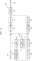
- FIG. 1A is a block diagram of an inter-layer video encoding apparatus 10 according to various embodiments.
- the inter-layer video encoding apparatus 10 includes a first layer encoder 12 and a second layer encoder 14.
- the second layer encoder 14 may include a neighboring sample determiner 16 and an illumination compensation parameter determiner 18.
- the second layer encoder 14 may further include an illumination compensation determiner (not shown) for determining whether to perform illumination compensation on a second layer current block.
- the neighboring sample determiner 16 and the illumination compensation parameter determiner 18 may be located outside the second layer encoder 14.
- the inter-layer video encoding apparatus 10 may classify a plurality of image sequences according to layers, may encode each of the image sequences according to a scalable video coding scheme, and may output separate streams including data encoded according to layers.
- the inter-layer video encoding apparatus 10 may encode a first layer image sequence and a second layer image sequence in different layers.
- the first layer encoder 12 may encode first layer images and output a first layer stream including the encoded data of the first layer images.
- the second layer encoder 14 may encode second layer images and output a second layer stream including the encoded data of the second layer images.
- low resolution images may be encoded as first layer images, and high resolution images may be encoded as second layer images.
- An encoding result of the first layer images may be output as a first layer stream, and an encoding result of the second layer images may be output as a second layer stream.
- a multiview video may be encoded according to a scalable video coding scheme.
- Left-view images may be encoded as first layer images and right-view images may be encoded as second layer images.
- central-view images, left-view images, and right-view images may be each encoded, wherein the central-view images are encoded as first layer images, the left-view images are encoded as second layer images, and the right-view images are encoded as third layer images.
- a central-view texture image, a central-view depth image, a left-view texture image, a left-view depth image, a right-view texture image, and a right-view depth image may be respectively encoded as a first layer image, a second layer image, a third layer image, a fourth layer image, a fifth layer image, and a sixth layer image.
- a central-view texture image, a central-view depth image, a left-view depth image, a left-view texture image, a right-view depth image, and a right-view texture image may be respectively encoded as a first layer image, a second layer image, a third layer image, a fourth layer image, a fifth layer image, and a sixth layer image.
- a scalable video coding method may be performed according to temporal hierarchical prediction based on temporal scalability.
- a first layer stream including encoding information generated by encoding base frame rate images may be output.
- Temporal levels may be classified according to frame rates and each temporal level may be encoded according to layers.
- a second layer stream including encoding information of a high frame rate may be output by further encoding higher frame rate images by referring to the base frame rate images.
- scalable video coding may be performed on a first layer and a plurality of extension layers (e.g., a second layer, a third layer, ..., and a K-th layer).
- first layer images and second to K-th layer images may be encoded.
- a result of encoding the first layer images may be output as a first layer stream
- results of encoding the second to K-th layer images may be output as second to K-th layer streams, respectively.
- the inter-layer video encoding apparatus 10 may perform inter prediction to predict a current image with reference to images of a single layer. Due to inter prediction, a motion vector indicating motion information between a current image and a reference image, and residuals between the current image and the reference image may be generated.
- the inter-layer video encoding apparatus 10 may perform inter-layer prediction to predict second layer images with reference to first layer images.
- the inter-layer video encoding apparatus 10 may perform inter-layer prediction between a first layer image and a third layer image and between a second layer image and a third layer image based on a multilayer prediction structure.
- a displacement component between the current image and a reference image of a different layer, and a residual component between the current image and the reference image of the different layer may be generated.
- the inter-layer video encoding apparatus 10 may perform encoding based on blocks of each image of a video, according to layers.
- a block may have a square shape, a rectangular shape, or an arbitrary geometrical shape, and is not limited to a data unit having a predetermined size.
- the block may be a maximum coding unit, a coding unit, a prediction unit, or a transformation unit, among coding units according to a tree structure.
- a largest coding unit including coding units of a tree structure may be called differently, such as a coding tree unit, a coding block tree, a block tree, a root block tree, a coding tree, a coding root, or a tree trunk.
- Video encoding and decoding methods based on coding units according to a tree structure will be described below with reference to FIGS. 8 through 20 .
- Inter prediction and inter-layer prediction may be performed based on a data unit, such as a coding unit, a prediction unit, or a transformation unit.
- the first layer encoder 12 may generate symbol data by performing source coding operations including inter prediction or intra prediction on first layer images.
- Symbol data indicates a sample value of each encoding parameter and a sample value of a residual.
- the first layer encoder 12 may generate symbol data by performing inter or intra prediction, transformation, and quantization on samples of a data unit of first layer images, and may generate a first layer stream by performing entropy encoding on the symbol data.
- the second layer encoder 14 may encode second layer images based on coding units of a tree structure.
- the second layer encoder 14 may generate symbol data by performing inter/intra prediction, transformation, and quantization on samples of a coding unit of second layer images, and generate a second layer stream by performing entropy encoding on the symbol data.
- the second layer encoder 14 may perform inter-layer prediction to predict a second layer image by using reconstructed samples of a first layer image.
- the second layer encoder 14 may generate a predicted second layer image by using a reconstructed first layer image, and encode a prediction error between an original second layer image and the predicted second layer image.
- the second layer encoder 14 may perform inter-layer prediction on the second layer image per block, e.g., per coding unit or prediction unit.
- a block of the reconstructed first layer image to be referred by a block of the second layer image may be determined.
- a reference block of the first layer image provided at a location corresponding to the location of a current block of the second layer image may be determined.
- the second layer encoder 14 may determine a second layer prediction block by using the first layer reference block corresponding to the second layer block.
- the second layer encoder 14 may use the second layer prediction block determined by using the first layer reference block according to an inter-layer prediction structure, as a reference image for inter-layer prediction with respect to a second layer original block.
- the second layer encoder 14 may perform entropy encoding by transforming and quantizing an error, i.e., a residual component according to inter-layer prediction, between a sample value of a second layer prediction block and a sample value of a second layer original block, by using a reconstructed first layer image.
- the second layer encoder 14 may encode a current layer image sequence with reference to the first layer images reconstructed based on the inter-layer prediction structure.
- the second layer encoder 14 may encode the second layer image sequence based on a single layer prediction structure without reference to samples of another layer. Accordingly, it should be noted that the second layer encoder 14 does not always perform inter-layer prediction to encode the second layer image sequence.
- the first layer encoder 12 may encode a first view video and the second layer encoder 14 may encode a second view video.
- the different view videos may be obtained by using different cameras or different lenses. Since different views may have different characteristics of shooting angles, lighting levels, or imaging devices (e.g., cameras or lenses), an illumination mismatch may occur between the videos obtained in different views. This illumination mismatch phenomenon may be related to the difference of sample values between the different view videos.
- the second layer encoder 14 of the inter-layer video encoding apparatus 10 may compensate for and encode an illumination difference between different view videos. For example, an illumination difference between the first view image to be encoded by the first layer encoder 12 and the second view image to be encoded by the second layer encoder 14 may be encoded. Since the illumination difference between the first view image and the second view image is encoded, illumination compensation may be performed when the second layer encoder 14 encodes the second view video.
- the inter-layer video encoding apparatus 10 may determine whether to perform illumination compensation, in consideration of characteristics per predetermined data unit such as a slice or block of a current image, e.g., partition type information of a current block.
- the inter-layer video encoding apparatus 10 may generate a second layer bitstream including a parameter indicating whether to perform illumination compensation.
- an illumination compensation parameter may be used for illumination compensation between a first layer block and a second layer block.
- the illumination compensation parameter may include at least one of a scale factor and an offset.
- the illumination compensation parameter including the scale factor and the offset for illumination compensation between block units may be transmitted in a bitstream or induced by using neighboring sample values of a second layer current block and neighboring sample values of a first layer reference block corresponding to the current block.
- the neighboring sample determiner 16 of the second layer encoder 14 may determine a reference location of the first layer image, and determine the neighboring sample values of the first layer reference block based on the reference location.
- a disparity vector indicating a view difference between layers may be used to determine the first layer reference block corresponding to the second layer current block.
- the disparity vector may be transmitted in a bitstream or induced from other types of coding information.
- the disparity vector may indicate the reference location of the first layer image corresponding to the location of the second layer current block.
- the location of the second layer current block may be the location of a top-left corner sample of the current block as a base location.
- the reference location of the first layer image may be the location of a top-left corner sample of the first layer reference block.
- the neighboring sample determiner 16 may determine neighboring sample locations based on the reference location.
- the neighboring sample locations may include top sample locations and left sample locations adjacent to the first layer reference block and determined based on the reference location.
- the neighboring sample locations are locations for determining the neighboring sample values used to induce the illumination compensation parameter, and may be locations spaced apart from the reference location by a predetermined offset.
- the illumination compensation parameter determiner 18 of the second layer encoder 14 may determine the neighboring sample values based on whether the neighboring sample locations are valid, and determine the illumination compensation parameter of the second layer current block based on the determined neighboring sample values.
- the fact that the neighboring sample locations are valid may mean that the neighboring sample locations are provided within the first layer image. A method of determining the illumination compensation parameter will be described in detail below with reference to FIG. 4 .
- the neighboring sample locations of the reference block are outside a boundary of the first layer image, no neighboring sample values of the reference block may be present.
- coding efficiency may be reduced.
- the amount of calculation for coding may be increased to determine whether the neighboring sample locations are valid.
- the inter-layer video encoding apparatus 10 may change the neighboring sample locations based on boundary locations of the first layer image and determine the illumination compensation parameter of the second layer current block by using sample values of the boundary of the first layer image.
- the inter-layer video encoding apparatus 10 does not need to check validity of the neighboring sample values and may obtain more accurate sample values, thereby increasing coding efficiency.
- the inter-layer video encoding apparatus 10 may not check validity of the neighboring sample values of the first layer and may perform illumination compensation based on whether neighboring sample values of the second layer current block are valid.
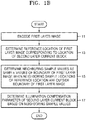
- FIG. 1B is a flowchart of an inter-layer video encoding method according to various embodiments.
- the inter-layer video encoding apparatus 10 may encode a first layer image and output a first layer bitstream including the encoded data.
- the inter-layer video encoding apparatus 10 may determine a reference location of the first layer image corresponding to the location of a second layer current block.
- the inter-layer video encoding apparatus 10 may obtain and use a disparity vector of the second layer current block indicating a first layer reference block.
- the disparity vector may be induced from neighboring blocks of the current block. Otherwise, the disparity vector may be induced from a depth map block corresponding thereto. Alternatively, the disparity vector may be obtained from a bitstream.
- the inter-layer video encoding apparatus 10 may determine the reference location of the first layer image corresponding to the location of the second layer current block, by using the disparity vector.
- the reference location of the first layer image may be the location of a top-left sample of the first layer reference block corresponding to the second layer current block.
- the location of the first layer image indicated by the disparity vector of the second layer current block may be a sub-pel location.
- the sub-pel location may be a pixel location other than an integer-pel location.
- the inter-layer video encoding apparatus 10 may determine an integer-pel location adjacent to the sub-pel location as the reference location to reduce complexity of calculation. Alternatively, when the disparity vector indicates a sub-pel location, the inter-layer video encoding apparatus 10 may determine the sub-pel location as the reference location to improve accuracy of an illumination compensation parameter and thus to increase coding efficiency. A process of determining the reference location will be described in detail below with reference to FIGS. 6A to 7B .
- the inter-layer video encoding apparatus 10 may determine the first layer reference block based on the determined reference location.
- the reference location may be the location of a top-left corner of the first layer reference block.
- the inter-layer video encoding apparatus 10 may determine neighboring sample values by using sample values of the boundary of the first layer image.
- the inter-layer video encoding apparatus 10 may determine the first layer neighboring sample locations based on the reference location.
- the neighboring sample locations may be determined as locations spaced apart from the reference location by a predetermined offset.
- the inter-layer video encoding apparatus 10 may determine whether the determined neighboring sample locations are outside the boundary of the first layer image. For example, the inter-layer video encoding apparatus 10 may determine whether the neighboring sample locations are outside the boundary of the first layer image, by comparing the neighboring sample locations to boundary locations of the first layer image. The inter-layer video encoding apparatus 10 may compare first component values of the neighboring sample locations to a left boundary and a right boundary of the first layer image, and compare second component values of the neighboring sample locations to a top boundary and a bottom boundary of the first layer image.
- the first component values may be x component values
- the second component values may be y component values.
- the inter-layer video encoding apparatus 10 may determine the neighboring sample values by using the sample values of the boundary of the first layer image. For example, the inter-layer video encoding apparatus 10 may change the neighboring sample locations based on the boundary locations of the first layer image, and the neighboring sample values may be the sample values of the boundary of the first layer image.
- the inter-layer video encoding apparatus 10 may determine the neighboring sample values by clipping the neighboring sample locations based on the boundary of the first layer image. For example, when the first component values of the neighboring sample locations are outside the left boundary or the right boundary of the first layer image, the inter-layer video encoding apparatus 10 may change the neighboring sample values into sample values of the left boundary or the right boundary of the first layer image. Alternatively, when the second component values of the neighboring sample locations are outside the top boundary or the bottom boundary of the first layer image, the inter-layer video encoding apparatus 10 may change the neighboring sample values into sample values of the top boundary or the bottom boundary of the first layer image.
- the first component values may be horizontal component values
- the second component values may be vertical component values.
- the inter-layer video encoding apparatus 10 may determine the neighboring sample values by padding the neighboring sample values of the reference location by using the sample values of the boundary of the first layer image.
- the inter-layer video encoding apparatus 10 may determine a first layer illumination compensation sample list including the determined neighboring sample values.
- the inter-layer video encoding apparatus 10 may determine an illumination compensation parameter of the second layer current block based on the determined neighboring sample values.
- the illumination compensation parameter may include at least one of a scale factor and an offset.
- the inter-layer video encoding apparatus 10 may determine the illumination compensation parameter by comparing the determined neighboring sample values of the first layer reference block to neighboring sample values of the second layer current block. For example, the inter-layer video encoding apparatus 10 may determine the illumination compensation parameter by comparing the first layer illumination compensation sample list to a second layer illumination compensation sample list. A method of determining the illumination compensation parameter will be described in detail below with reference to FIG. 4 .
- the inter-layer video encoding apparatus 10 may generate a second layer bitstream including information indicating whether to perform illumination compensation, and inter-layer prediction information between the first layer reference block and the second layer current block, an illumination value of which is compensated based on the illumination compensation parameter.
- the inter-layer video encoding apparatus 10 may encode and transmit information indicating whether to perform illumination compensation on the current block, and the disparity vector used to determine the illumination compensation parameter, in a bitstream.
- the inter-layer video encoding apparatus 10 may not transmit the information indicating whether to perform illumination compensation, and the disparity vector.
- the inter-layer video encoding apparatus 10 may encode and transmit the information indicating whether to perform illumination compensation, in a bitstream, and may encode and transmit the disparity vector used to determine the illumination compensation parameter, in a bitstream, or may not transmit the disparity vector when the disparity vector may be determined based on pre-encoded information.
- an error between the second layer image and the first layer image may be reduced and thus coding efficiency of inter-layer prediction may be improved.
- the inter-layer video encoding apparatus 10 may include a central processor (not shown) for controlling all of the first layer encoder 12, the second layer encoder 14, the neighboring sample determiner 16, and the illumination compensation parameter determiner 18.
- the first layer encoder 12, the second layer encoder 14, the neighboring sample determiner 16, and the illumination compensation parameter determiner 18 may be controlled by individual processors (not shown) and the processors may operate in association with each other to control the inter-layer video encoding apparatus 10.
- the first layer encoder 12, the second layer encoder 14, the neighboring sample determiner 16, and the illumination compensation parameter determiner 18 may be controlled by an external processor (not shown) of the inter-layer video encoding apparatus 10.
- the inter-layer video encoding apparatus 10 may include one or more data storages (not shown) for storing input and output data of the first layer encoder 12, the second layer encoder 14, the neighboring sample determiner 16, and the illumination compensation parameter determiner 18.
- the inter-layer video encoding apparatus 10 may include a memory controller (not shown) for controlling data input and output of the data storages.
- the inter-layer video encoding apparatus 10 may operate in cooperation with an internal video encoding processor installed therein or an external video encoding processor so as to perform video encoding operations including transformation.
- the internal video encoding processor of the inter-layer video encoding apparatus 10 may perform the video encoding operations as a separate processor.
- basic video encoding operations may be realized as the inter-layer video encoding apparatus 10, a central processing apparatus, or a graphic processing apparatus includes a video encoding processing module.
- FIG. 2A is a block diagram of an inter-layer video decoding apparatus 20 according to various embodiments.
- the inter-layer video decoding apparatus 20 includes a first layer decoder 22 and a second layer decoder 24.
- the second layer decoder 24 may include a neighboring sample determiner 26 and an illumination compensation parameter determiner 28.
- the second layer decoder 24 may further include an illumination compensation determiner (not shown) for determining whether to perform illumination compensation on a second layer current block.
- the neighboring sample determiner 26 and the illumination compensation parameter determiner 28 may be located outside the second layer decoder 24.
- the inter-layer video decoding apparatus 20 may receive bitstreams according to layers, via a scalable encoding scheme.
- the number of layers of bitstreams received by the inter-layer video decoding apparatus 20 is not limited. However, for convenience of description, an embodiment in which the first layer decoder 22 of the inter-layer video decoding apparatus 20 receives and decodes a first layer stream and the second layer decoder 24 receives and decodes a second layer stream will be described.
- the inter-layer video decoding apparatus 20 may receive a stream in which image sequences having different resolutions are encoded in different layers.
- a first layer stream may be decoded to reconstruct an image sequence having low resolution and a second layer stream may be decoded to reconstruct an image sequence having high resolution.
- a multiview video may be decoded according to a scalable video coding scheme.
- a first layer stream may be decoded to reconstruct left-view images.
- a second layer stream in addition to the first layer stream may be further decoded to reconstruct right-view images.
- a first layer stream may be decoded to reconstruct central-view images.
- a second layer stream in addition to the first layer stream may be further decoded to reconstruct left-view images.
- a third layer stream in addition to the first layer stream may be further decoded to reconstruct right-view images.
- a scalable video coding method based on temporal scalability may be performed.
- a first layer stream may be decoded to reconstruct base frame rate images.
- a second layer stream may be further decoded to reconstruct high frame rate images.
- first layer images may be reconstructed from a first layer stream, and when a second layer stream is further decoded by referring to reconstructed first layer images, second layer images may be further reconstructed.
- K-th layer stream is further decoded by referring to reconstructed second layer images, K-th layer images may be further reconstructed.
- the inter-layer video decoding apparatus 20 may obtain encoded data of first layer images and second layer images from a first layer stream and a second layer stream, and in addition, may further obtain a motion vector generated via inter prediction and prediction information generated via inter-layer prediction.
- the inter-layer video decoding apparatus 20 may decode inter-predicted data per layer, and may decode inter-layer predicted data between a plurality of layers. Reconstruction may be performed through motion compensation and inter-layer decoding based on a coding unit or a prediction unit.
- Images may be reconstructed by performing motion compensation for a current image by referencing reconstructed images predicted via inter prediction of a same layer, with respect to each layer stream.
- Motion compensation is an operation in which a reconstructed image of a current image is reconstructed by synthesizing a reference image determined by using a motion vector of the current image and a residual component of the current image.
- the inter-layer video decoding apparatus 20 may perform inter-layer decoding with reference to the first layer images to reconstruct the inter-layer predicted second layer images.
- the inter-layer decoding refers to an operation of configuring a reconstructed image of a current image by combining an another-layer reference image determined to predict the current image, and residuals of the current image.
- the inter-layer video decoding apparatus 20 may perform inter-layer decoding for reconstructing third layer images predicted by referring to second layer images.
- An inter-layer prediction structure will be described below with reference to FIG. 3 .
- the second layer decoder 24 may decode a second layer stream without having to reference a first layer image sequence. Accordingly, it should not be limitedly construed that the second layer decoder 24 performs inter-layer prediction to decode a second layer image sequence.
- the inter-layer video decoding apparatus 20 performs decoding according to blocks of each image of a video.
- a block may be, from among coding units according to a tree structure, a largest coding unit, a coding unit, a prediction unit, or a transformation unit.
- the first layer decoder 22 may decode a first layer image by using parsed encoding symbols of the first layer image.
- the first layer decoder 22 may perform decoding based on the coding units of the tree structure, according to a largest coding unit of a first layer stream.
- the first layer decoder 22 may obtain decoding information and decoded data by performing entropy decoding per largest coding unit.
- the first layer decoder 22 may reconstruct a residual component by performing inverse quantization and inverse transformation on encoded data obtained from a stream.
- the first layer decoder 22 according to another embodiment may directly receive a bitstream of quantized transformation coefficients.
- the residual component of images may be reconstructed by performing inverse quantization and inverse transformation on quantized transformation coefficients.
- the first layer decoder 22 may reconstruct first layer images by combining the prediction image and the residual component via motion compensation between same layer images.
- the second layer decoder 24 may generate a second layer prediction image by using samples of a reconstructed first layer image.
- the second layer decoder 24 may obtain a prediction error according to inter-layer prediction by decoding a second layer stream.
- the second layer decoder 24 may generate a reconstructed second layer image by combining a second layer prediction image and the prediction error.
- the second layer decoder 24 may determine a second layer prediction image by using a first layer reference image decoded by the first layer decoder 22.
- the second layer decoder 24 may determine a block of a first layer image which is to be referenced by a block such as a coding unit or a prediction unit of a second layer image. For example, a reference block of the first layer image provided at a location corresponding to the location of a current block of the second layer image may be determined.
- the second layer decoder 24 may determine a second layer prediction block by using the first layer reference block corresponding to the second layer block.
- the second layer decoder 24 may use the second layer prediction block determined by using the first layer reference block based on an inter-layer prediction structure, as a reference image for inter-layer prediction on a second layer original block. In this case, the second layer decoder 24 may reconstruct the second layer block by combining sample values of the second layer prediction block determined by using the reconstructed first layer image, and residuals based on inter-layer prediction.
- the second layer decoder 24 may interpolate the first layer reference image to adjust the resolution thereof to be the same as the resolution of the original second layer image.
- the interpolated first layer reference image may be determined as a predicted second layer image for inter-layer prediction.
- the first layer decoder 22 of the inter-layer video decoding apparatus 20 may reconstruct a first layer image sequence by decoding a first layer stream
- the second layer decoder 24 may reconstruct a second layer image sequence by decoding a second layer stream.
- the illumination compensation parameter determiner 28 of the inter-layer video decoding apparatus 20 may compensate for and reconstruct an illumination difference between different view videos. For example, an illumination difference between the first view image to be decoded by the first layer decoder 22 and the second view image to be encoded by the second layer decoder 24 may be obtained from a bitstream. Since the illumination difference between the first view image and the second view image is obtained, whether to perform illumination compensation may be determined when the second layer decoder 24 decodes the second view video.
- the inter-layer video decoding apparatus 20 may use an illumination compensation parameter for illumination compensation between a first layer block and a second layer block.
- the illumination compensation parameter may include at least one of a scale factor and an offset.
- the inter-layer video decoding apparatus 20 may receive information indicating whether to perform illumination compensation, from the bitstream, and determine whether to perform illumination compensation on the second layer current block. Alternatively, the inter-layer video decoding apparatus 20 may determine whether to perform illumination compensation, in consideration of other types of coding information, e.g., partition type information of a current block.
- the neighboring sample determiner 26 of the second layer decoder 24 may determine a reference location of the first layer image, and determine neighboring sample values of the first layer reference block based on the reference location.
- a disparity vector indicating a view difference between layers may be used to determine the first layer reference block corresponding to the second layer current block.
- the disparity vector may be transmitted in a bitstream or induced from other types of coding information.
- the disparity vector may indicate the reference location of the first layer image corresponding to the location of the second layer current block.
- the location of the second layer current block may be the location of a top-left corner sample of the current block as a base location.
- the reference location of the first layer image may be the location of a top-left corner sample of the first layer reference block.
- the neighboring sample determiner 26 may determine neighboring sample locations based on the reference location.
- the neighboring sample locations may include top sample locations and left sample locations adjacent to the first layer reference block and determined based on the reference location.
- the neighboring sample locations may be locations spaced apart from the reference location by a predetermined offset.
- the illumination compensation parameter determiner 28 of the second layer decoder 24 may determine the neighboring sample values based on whether the neighboring sample locations are valid, and determine the illumination compensation parameter of the second layer current block based on the determined neighboring sample values.
- the fact that the neighboring sample locations are valid may mean that the neighboring sample locations are provided within the first layer image. A method of determining the illumination compensation parameter will be described in detail below with reference to FIG. 4 .
- the neighboring sample locations of the reference block are outside a boundary of the first layer image, no neighboring sample values of the reference block may be present.
- coding efficiency may be reduced.
- the amount of calculation for coding may be increased to determine whether the neighboring sample locations are valid.
- the inter-layer video decoding apparatus 20 may change the neighboring sample locations based on boundary locations of the first layer image and determine the illumination compensation parameter of the second layer current block by using sample values of the boundary of the first layer image.
- the inter-layer video decoding apparatus 20 does not need to check validity of the neighboring sample values and may obtain more accurate sample values, thereby increasing coding efficiency.
- the inter-layer video decoding apparatus 20 may not check validity of the neighboring sample values of the first layer and may perform illumination compensation based on whether neighboring sample values of the second layer current block are valid.
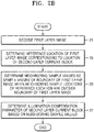
- FIG. 2B is a flowchart of an inter-layer video decoding method according to various embodiments.
- the inter-layer video decoding apparatus 20 may decode a first layer image.
- the inter-layer video decoding apparatus 20 may receive a first layer bitstream and decode the first layer image.
- the inter-layer video decoding apparatus 20 may determine a reference location of the first layer image corresponding to the location of a second layer current block.
- the inter-layer video decoding apparatus 20 may obtain and use a disparity vector of the second layer current block indicating a first layer reference block.
- the disparity vector may be induced from neighboring blocks of the current block.
- the disparity vector may be obtained from a bitstream.
- the inter-layer video decoding apparatus 20 may determine the reference location of the first layer image corresponding to the location of the second layer current block, by using the disparity vector.
- the reference location of the first layer image may be the location of a top-left sample of the first layer reference block corresponding to the second layer current block.
- the location of the first layer image indicated by the disparity vector of the second layer current block may be a sub-pel location.
- the sub-pel location may be a pixel location other than an integer-pel location.
- the inter-layer video decoding apparatus 20 may determine an integer-pel location adjacent to the sub-pel location as the reference location to reduce complexity of calculation. Alternatively, when the disparity vector indicates a sub-pel location, the inter-layer video decoding apparatus 20 may determine the sub-pel location as the reference location to improve accuracy of an illumination compensation parameter and thus to increase coding efficiency. A process of determining the reference location will be described in detail below with reference to FIGS. 6A to 7B .
- the inter-layer video decoding apparatus 20 may determine the first layer reference block based on the determined reference location.
- the reference location may be the location of a top-left corner of the first layer reference block.
- the inter-layer video decoding apparatus 20 may determine neighboring sample values by using sample values of the boundary of the first layer image.
- the inter-layer video decoding apparatus 20 may determine the first layer neighboring sample locations based on the reference location.
- the neighboring sample locations may be determined as locations spaced apart from the reference location by a predetermined offset.
- the inter-layer video decoding apparatus 20 may determine whether the determined neighboring sample locations are outside the boundary of the first layer image. For example, the inter-layer video decoding apparatus 20 may determine whether the neighboring sample locations are outside the boundary of the first layer image, by comparing the neighboring sample locations to boundary locations of the first layer image. The inter-layer video decoding apparatus 20 may compare first component values of the neighboring sample locations to a left boundary and a right boundary of the first layer image, and compare second component values of the neighboring sample locations to a top boundary and a bottom boundary of the first layer image.
- the first component values may be x component values
- the second component values may be y component values.
- the inter-layer video decoding apparatus 20 may determine the neighboring sample values by using the sample values of the boundary of the first layer image. For example, the inter-layer video decoding apparatus 20 may change the neighboring sample locations based on the boundary locations of the first layer image, and the neighboring sample values may be the sample values of the boundary of the first layer image.
- the inter-layer video decoding apparatus 20 may determine the neighboring sample values by clipping the neighboring sample locations based on the boundary of the first layer image. For example, when the first component values of the neighboring sample locations are outside the left boundary or the right boundary of the first layer image, the inter-layer video decoding apparatus 20 may change the neighboring sample values into sample values of the left boundary or the right boundary of the first layer image. Alternatively, when the second component values of the neighboring sample locations are outside the top boundary or the bottom boundary of the first layer image, the inter-layer video decoding apparatus 20 may change the neighboring sample values into sample values of the top boundary or the bottom boundary of the first layer image.
- the first component values may be horizontal component values
- the second component values may be vertical component values.
- the inter-layer video decoding apparatus 20 may determine the neighboring sample values by padding the neighboring sample values of the reference location by using the sample values of the boundary of the first layer image.
- the inter-layer video decoding apparatus 20 may determine a first layer illumination compensation sample list including the determined neighboring sample values.
- the inter-layer video decoding apparatus 20 may determine an illumination compensation parameter of the second layer current block based on the determined neighboring sample values.
- the illumination compensation parameter may include at least one of a scale factor and an offset.
- the inter-layer video decoding apparatus 20 may determine the illumination compensation parameter by comparing the determined neighboring sample values of the first layer reference block to neighboring sample values of the second layer current block. For example, the inter-layer video decoding apparatus 20 may determine the illumination compensation parameter by comparing the first layer illumination compensation sample list to a second layer illumination compensation sample list. A method of determining the illumination compensation parameter will be described in detail below with reference to FIG. 4 .
- the inter-layer video decoding apparatus 20 may decode the second layer block on which illumination compensation, an illumination value of which is compensated based on the determined illumination compensation parameter.
- the inter-layer video decoding apparatus 20 may include a central processor (not shown) for controlling all of the first layer decoder 22, the second layer decoder 24, the neighboring sample determiner 26, and the illumination compensation parameter determiner 28.
- the first layer decoder 22, the second layer decoder 24, the neighboring sample determiner 26, and the illumination compensation parameter determiner 28 may be controlled by individual processors (not shown) and the processors may operate in association with each other to control the inter-layer video decoding apparatus 20.
- the first layer decoder 22, the second layer decoder 24, the neighboring sample determiner 26, and the illumination compensation parameter determiner 28 may be controlled by an external processor (not shown) of the inter-layer video decoding apparatus 20.
- the inter-layer video decoding apparatus 20 may include one or more data storages (not shown) for storing input and output data of the first layer decoder 22, the second layer decoder 24, the neighboring sample determiner 26, and the illumination compensation parameter determiner 28.
- the inter-layer video decoding apparatus 20 may include a memory controller (not shown) for controlling data input and output of the data storages.
- the inter-layer video decoding apparatus 20 may operate in cooperation with an internal video decoding processor installed therein or an external video decoding processor so as to perform video decoding operations including inverse transformation.
- the internal video decoding processor of the inter-layer video decoding apparatus 20 may include an individual processor or a video decoding module included in the inter-layer video decoding apparatus 20, a central processing unit, or a graphics processing unit to perform basic video decoding operations.
- the inter-layer video decoding apparatus 20 compensates for an illumination difference between different layer images or different views per a certain type of block or slice to decode a second layer image, a reconstructed first layer image and a reconstructed second layer image may have uniform illumination values.
- the inter-layer video encoding apparatus 10 compensates for an illumination difference between different layer images per a certain type of block or slice, residuals between a predicted image and an original image may be reduced. Accordingly, coding efficiency may be increased.
- coding efficiency may be further increased by more accurately determining first layer neighboring sample values used to induce an illumination compensation parameter, based on a boundary of the first layer image.
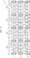
- FIG. 3 illustrates an inter-layer prediction structure according to an embodiment.
- the inter-layer video encoding apparatus 10 may prediction-encode base-view images, left-view images, and right-view images based on a reproduction order 30 of a multiview video prediction structure.
- the reproduction order 30 of the multiview video prediction structure images of the same view are arranged in a horizontal direction. Accordingly, the left-view images indicated by 'Left' are arranged in the horizontal direction in a row, the base view images indicated by 'Center' are arranged in the horizontal direction in a row, and the right-view images indicated by 'Right' are arranged in the horizontal direction in a row.
- the base view images may be central-view images.
- images having the same picture order count (POC) order are arranged in a vertical direction.
- a POC order of images indicates a reproduction order of images forming a video.
- 'POC X' indicated in the reproduction order 30 of the multiview video prediction structure indicates a relative reproduction order of images in a corresponding column, wherein a reproduction order is in front when a value of X is low, and is behind when the value of X is high.
- the left-view images indicated by 'Left' are arranged in the horizontal direction according to the POC order (reproduction order)
- the base view images indicated by 'Center' are arranged in the horizontal direction according to the POC order (reproduction order)
- the right-view images indicated by 'Right' are arranged in the horizontal direction according to the POC order (reproduction order).
- the left-view image and the right-view image located on the same column as the base view image have different views but the same POC order (reproduction order).
- Each GOP includes images between consecutive anchor pictures, and one anchor picture (key picture).
- An anchor picture is a random access point, and when a reproduction location is arbitrarily selected from images arranged according to a reproduction order, i.e., a POC order, while reproducing a video, an anchor picture closest to the reproduction location according to the POC order is reproduced.
- the base layer images include base layer anchor pictures 31, 32, 33, 34, and 35
- the left-view images include left-view anchor pictures 131, 132, 133, 134, and 135
- the right-view images include right-view anchor pictures 231, 232, 233, 234, and 235.
- Multiview images may be reproduced and predicted (reconstructed) according to a GOP order.
- images included in GOP 0 may be reproduced, and then images included in GOP 1 may be reproduced, according to views. That is, images included in each GOP may be reproduced in an order of GOP 0, GOP 1, GOP 2, and GOP 3.
- the images included in GOP 0 may be predicted (reconstructed), and then the images included in GOP 1 may be predicted (reconstructed), according to views. That is, the images included in each GOP may be predicted (reconstructed) in an order of GOP 0, GOP 1, GOP 2, and GOP 3.
- inter-view prediction inter-layer prediction
- inter prediction inter-layer prediction
- an image where an arrow starts is a reference image
- an image where an arrow ends is an image predicted by using a reference image.
- a prediction result of base view images may be encoded and then output in a form of a base view image stream, and a prediction result of additional view images may be encoded and then output in a form of a layer bitstream. Also, a prediction encoding result of left-view images may be output as a first layer bitstream, and a prediction encoding result of right-view images may be output as a second layer bitstream.
- the base layer anchor pictures 31, 32, 33, 34, and 35 of an I-picture type do not refer to other images, but remaining images of B-and b-picture types are predicted by referring to other base view images.
- Images of a B-picture type are predicted by referring to an anchor picture of an I-picture type, which precedes the images of a B-picture type according to a POC order, and a following anchor picture of an I-picture type.
- Images of a b-picture type are predicted by referring to an anchor picture of an I-type, which precedes the image of a b-picture type according a POC order, and a following image of a B-picture type, or by referring to an image of a B-picture type, which precedes the images of a b-picture type according to a POC order, and a following anchor picture of an I-picture type.
- Inter-view prediction (inter-layer prediction) that references different view images, and inter prediction that references same view images are performed on each of left-view images and right-view images.
- Inter-view prediction may be performed on the left-view anchor pictures 131, 132, 133, 134, and 135 by respectively referring to the base view anchor pictures 31, 32, 33, 34, and 35 having the same POC order.
- Inter-view prediction may be performed on the right-view anchor pictures 231, 232, 233, 234, and 235 by respectively referring to the base view anchor pictures 31, 32, 33, 34, and 35 or the left-view anchor pictures 131, 132, 133, 134, and 135 having the same POC order.
- inter-view prediction may be performed on remaining images other than the left-view images 131, 132, 133, 134, and 135 and the right-view images 231, 232, 233, 234, and 235 by referring to other view images having the same POC.
- Remaining images other than the anchor pictures 131, 132, 133, 134, 135, 231, 232, 233, 234, and 235 from among left-view images and right-view images are predicted by referring to the same view images.
- each of the left-view images and the right-view images may not be predicted by referring to an anchor picture that has a preceding reproduction order from among additional view images of the same view.
- left-view images excluding a left-view anchor picture that precedes the current left-view image in a reproduction order may be referenced.
- right-view images excluding a right-view anchor picture that precedes the current right-view image in a reproduction order may be referenced.
- prediction may be performed by referring to a left-view image that belongs to a current GOP but is to be reconstructed before the current left-view image, instead of referring to a left-view image that belongs to a GOP before the current GOP of the current left-view image. The same is applied to a right-view image.
- the inter-layer video decoding apparatus 20 may reconstruct base view images, left-view images, and right-view images according to the reproduction order 30 of the multiview video prediction structure of FIG. 3 .
- Left-view images may be reconstructed via inter-view disparity compensation that references base view images and inter-image motion compensation that references left-view images.
- Right-view images may be reconstructed via inter-view disparity compensation that references base view images and left-view images, and inter-image motion compensation that references right-view images.
- Reference images may be reconstructed first for disparity compensation and motion compensation of left-view images and right-view images.
- left-view images may be reconstructed via inter-image motion compensation that references a reconstructed left-view reference image.
- right-view images may be reconstructed via inter-image motion compensation that references a reconstructed right-view reference image.
- a left-view image that belongs to a current GOP of the current left-view image but is to be reconstructed before the current left-view image may be referenced, and a left-view image that belongs to a GOP before the current GOP is not referenced. The same is applied to a right-view image.
- the inter-layer video encoding apparatus 10 and the inter-layer video decoding apparatus 20 may determine whether to perform illumination compensation, based on image characteristics. For example, whether to perform illumination compensation on a block may be determined based on a coding mode of the block, a prediction direction of the block, and a coding type, which are determined based on rate-distortion (RD) optimization.
- RD rate-distortion
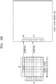
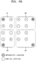
- FIG. 4 illustrates an example of a method of determining an illumination compensation parameter, according to an embodiment.
- the inter-layer video decoding apparatus 20 may obtain information indicating whether to perform illumination compensation per coding unit, and determine the illumination compensation parameter for each color component (e.g., Y, U, or V) of each prediction direction per prediction unit of each coding unit.
- the illumination compensation parameter may be determined based on neighboring samples of a current block and neighboring samples of a reference block of another layer corresponding to the current block. That is, the illumination compensation parameter may be determined by comparing neighboring samples of the reference block of a first layer to neighboring samples of the current block of a second layer.
- the illumination compensation parameter may include at least one of a scale factor a and an offset b.
- the neighboring samples of the current block used to induce the illumination compensation parameter may refer to usable neighboring samples of the current block, which are already reconstructed before the current block is reconstructed. Accordingly, when the neighboring samples of the current block are not usable, the illumination compensation parameter may not be induced. That is, the inter-layer video decoding apparatus 20 may determine whether to perform illumination compensation, based on whether the neighboring sample values of the current block are usable.
- a first layer reference block 45 corresponding to a second layer current block 40 should be found.
- a disparity vector may be used.
- the disparity vector is a vector indicating a location difference between the second layer current block 40 and the first layer reference block 45.
- FIG. 4 shows the second layer current block 40 configured as an 8x8 block and the first layer reference block 45 corresponding to the second layer current block 40.
- the inter-layer video decoding apparatus 20 may determine a reference location 46 of a first layer image indicated by the disparity vector, based on a location 41 of the second layer current block 40.
- the location 41 of the current block is a base location of the current block 40 and may be the location of a top-left corner thereof, and the reference location 46 may be the location of a top-left corner of the first layer reference block 45 corresponding to the second layer current block 40.
- the illumination compensation parameter may be determined by using neighboring samples 42 of the second layer current block 40 and neighboring samples 47 of the first layer reference block 45.
- the illumination compensation parameter may be determined by using all or a part of the neighboring samples 42 and 47. For example, an average illumination difference between the neighboring samples 42 and the neighboring samples 47 may be determined as an offset, and thus illumination compensation may be performed on the current block 40 by the determined offset.
- the inter-layer video decoding apparatus 20 may determine the illumination compensation parameters a and b by using the neighboring samples 42 and 47. That is, the inter-layer video decoding apparatus 20 may determine the illumination compensation parameter based on a first layer illumination compensation sample list including the neighboring samples 47 of the first layer reference block 45 and a second layer illumination compensation sample list including the neighboring samples 42 of the second layer current block 40.
- the inter-layer video decoding apparatus 20 may calculate the illumination compensation parameter. Accordingly, data to be transmitted may be reduced.
- a method of calculating the illumination compensation parameter includes a linear regression scheme, an average of difference based prediction (ADP) scheme, and a difference of average based prediction (DAP) scheme, etc.
- the illumination compensation parameters a and b may be calculated by using Equation 1.
- N may be the number of neighboring samples of a block (N is 16 in FIG. 4 ), NB curr may be the value of the neighboring samples 42 of the current block 40, and NB ref may be the value of the neighboring samples 47 of the reference block 45.
- the inter-layer video decoding apparatus 20 may perform illumination compensation on the second layer current block 40 by using the determined illumination compensation parameter. For example, the inter-layer video decoding apparatus 20 may compensate for an illumination value Pred(x, y) of each sample of the current block 40 by using an illumination compensation model defined by Equation 2.
- Pred ′ x y a ⁇ Pred x y + b
- a coding operation for predicting an illumination difference between layers may increase the amount of calculation.
- an operation of multiplying an illumination value of each pixel by the scale factor a requires many clocks of a computer and thus load may be generated when illumination compensation is performed.
- the inter-layer video decoding apparatus 20 may perform illumination compensation by merely adding an offset in consideration of characteristics per predetermined data unit such as a slice or block of a current image. That is, illumination compensation using only an offset may be performed by using an illumination compensation model defined by Equation 3.
- Pred ′ x y Pred x y + b ′
- the inter-layer video decoding apparatus 20 may determine only the offset b'.
- the inter-layer video decoding apparatus 20 may determine a value obtained by adding the offset b' to the illumination value Pred(x, y) of each sample of the second layer current block 40, as an illumination value Pred'(x, y) of each sample of the illumination-compensated second layer current block 40. Since the illumination compensation model defined by Equation 3 does not include a multiplying operation but includes only an offset-adding operation, the amount of calculation required for illumination compensation may be reduced.
- inter-layer video decoding apparatus 20 determines the illumination compensation model and the illumination compensation parameter in FIG. 4 , it will be understood by one of ordinary skill in the art that the method described above in relation to FIG. 4 is also applicable to the inter-layer video encoding apparatus 10.
- FIGS. 5A and 5B illustrate an example of a process of determining neighboring sample locations of a first layer image 50, according to various embodiments.
- the inter-layer video decoding apparatus 20 may determine a first layer reference block 51 corresponding to a current block 53 of a second layer image 52 by using a disparity vector DV.
- the disparity vector DV may be transmitted in a bitstream or induced from other types of coding information.
- the inter-layer video decoding apparatus 20 may determine neighboring sample values by using sample values of the boundary of the first layer image 50.
- the neighboring sample values may be the sample values of the boundary of the first layer image 50.
- the inter-layer video decoding apparatus 20 does not need to check validity of the neighboring sample values and may obtain more accurate sample values, thereby increasing coding efficiency.
- the inter-layer video decoding apparatus 20 may not check validity of the neighboring sample values of the first layer and may perform illumination compensation based on whether neighboring sample values of the second layer current block 53 are valid.
- FIG. 5B a process of determining the neighboring sample values by the inter-layer video decoding apparatus 20 is shown.
- the inter-layer video decoding apparatus 20 may determine the neighboring sample values by using the sample values of the boundary of the first layer image 50.
- the inter-layer video decoding apparatus 20 may determine the neighboring sample values by changing the neighboring sample locations 54 and 55 based on boundary locations 56 and 57 of the first layer image 50. That is, the inter-layer video decoding apparatus 20 may determine the neighboring sample values by clipping the neighboring sample locations 54 and 55 of the reference location based on the boundary of the first layer image 50.
- the inter-layer video decoding apparatus 20 may compare first component values of the neighboring sample locations 54 and 55 to a left boundary and a right boundary of the first layer image 50, and compare second component values of the neighboring sample locations 54 and 55 to a top boundary and a bottom boundary of the first layer image 50.
- the first component values may be x component values
- the second component values may be y component values.
- the inter-layer video decoding apparatus 20 may determine the neighboring sample values by using sample values of the left boundary or the right boundary of the first layer image 50.
- the inter-layer video decoding apparatus 20 may determine the neighboring sample values by using sample values of the top boundary or the bottom boundary of the first layer image 50.
- the inter-layer video decoding apparatus 20 may determine top neighboring sample values of the first layer reference block 51 by using a sample value of a left boundary location 56 of the first layer image 50.
- the inter-layer video decoding apparatus 20 may determine left neighboring sample values of the first layer reference block 51 by using sample values of left boundary locations 57 of the first layer image 50.
- the top neighboring sample values of the first layer reference block 51 may correspond to the sample value of the left boundary location 56 of the first layer image 50, and the left neighboring sample values of the first layer reference block 51 may be the sample values of the left boundary locations 57 of the first layer image 50.
- the inter-layer video decoding apparatus 20 may determine the neighboring sample values by using sample values of the right boundary.
- the inter-layer video decoding apparatus 20 may determine the neighboring sample values by using sample values of the top or bottom boundary.
- the inter-layer video decoding apparatus 20 may change the first component values of the neighboring sample locations 54 and 55 based on left or right boundary locations of the first layer image 50.
- the inter-layer video decoding apparatus 20 may change the second component values of the neighboring sample locations 54 and 55 based on top or bottom boundary locations of the first layer image 50.
- the neighboring sample values may be sample values of the left or right boundary locations of the first layer image 50, or sample values of the top or bottom boundary locations of the first layer image 50.
- a method of determining the first layer neighboring sample values as described above in relation to FIG. 5B may be expressed as the following pseudo-code.
- curNbColFlag may be information indicating whether neighboring sample locations are top neighboring sample locations or left neighboring sample locations of a first layer reference location.
- availFlagCurLeftCol and availFlagCurAboveRow may be information indicating whether left sample values of a second layer current block are valid, and information indicating whether top sample values of the second layer current block are valid, respectively.
- xRefBlkLX and yRefBlkLX may indicate an x component and a y component of the first layer reference location, respectively.
- xRefBlkLX + xOff and yRefBlkLX + yOff may indicate x components and y components of the neighboring sample locations based on the first layer reference location, respectively.
- the x components (xRefBlkLX + xOff) of the neighboring sample locations may be clipped based on a left boundary location (0) of a first layer image, which is the minimum value, and a right boundary location ((pic_width_in_luma_samples / subWidth ) - 1) of the first layer image, which is the maximum value, and changed into new x components (xP) of the neighboring sample locations.
- the y components (yRefBlkLX + yOff) of the neighboring sample locations may be clipped based on a top boundary location (0) of the first layer image, which is the minimum value, and a bottom boundary location (( pic_height_in_luma_samples / subHeight ) - 1) of the first layer image, which is the maximum value, and changed into new y components (yP) of the neighboring sample locations.
- refRecSamplesLX[ xP ][ yP ] may indicate neighboring sample values of a reconstructed first layer image.
- the inter-layer video decoding apparatus 20 may determine a first layer illumination compensation sample list (refSampleListLX) including the neighboring sample values of the first layer image.
- the inter-layer video decoding apparatus 20 may determine a second layer illumination compensation sample list (curSampleList) including neighboring sample values of a second layer image.
- the inter-layer video decoding apparatus 20 may determine the neighboring sample values by padding the neighboring sample values of the reference location by using the sample values of a boundary of the first layer image.
- the inter-layer video decoding apparatus 20 determines the illumination compensation parameter by using the determined neighboring sample values of the first layer reference block 51, more accurate neighboring sample values may be predicted and thus coding efficiency may be increased.
- inter-layer video decoding apparatus 20 determines the first layer neighboring sample values used to induce the illumination compensation parameter in FIGS. 5A and 5B , it will be understood by one of ordinary skill in the art that the method described above in relation to FIGS. 5A and 5B is also applicable to the inter-layer video encoding apparatus 10.
- FIGS. 6A to 6C illustrate examples of a method of determining a reference location to determine first layer neighboring sample values, according to various embodiments.
- the inter-layer video decoding apparatus 20 may use a disparity vector indicating a view difference between layers, to determine a first layer reference block corresponding to a second layer current block.
- the disparity vector may be transmitted in a bitstream or induced from other types of coding information.
- the location of a first layer image indicated by the disparity vector of the second layer current block may be a sub-pel location.
- the sub-pel location may be a pixel location other than an integer-pel location.
- an integer-pel location adjacent to the sub-pel location may be the reference location of the first layer image to reduce complexity of calculation.
- FIGS. 6A to 6C illustrate examples of determining a neighboring integer-pel indicated by the disparity vector, according to embodiments.
- uppercase A, B, C, and D indicate integer-pel locations
- lowercase a to o indicate sub-pel locations
- the inter-layer video decoding apparatus 20 may determine an integer-pel location of a 1 ⁇ 1 block including the location of the first layer image indicated by the disparity vector at a base location of the second layer current block, as the first layer reference location.
- the first layer reference location may be an integer-pel location A.
- a method of determining the reference location by using the location of the first layer image indicated by the disparity vector at the base location of the current block as described above in relation to FIG. 6A may be expressed as the following pseudo-code.
- xRLX xC + mvLX 0 > > 2 + cIdx ? 1 : 0
- yRLX yC + mvLX 1 > > 2 + cIdx ? 1 : 0
- mvLX[0] and mvLX[1] may denote an x component and a y component of the disparity vector
- (xC, yC) may denote a location coordinate of the current block
- cIdx may denote a Y component or a depth map when the value thereof is 0
- a luma block and a chroma block have different sizes and thus may have different distances between integer-pixels.
- the method of determining the reference location may differ based on whether a conditional "cIdx? 1: 0" indicates a luma block or a chroma block.
- a reference block location (xRLX, yRLX) corresponding to the current block location (xC, yC) may be obtained based on a predetermined shift operation shown by then above pseudo-code.
- each of the current block location (xC, yC) and the reference block location (xRLX, yRLX) may be a coordinate value of a top-left corner of the block.
- each of the current block location (xC, yC) and the reference block location (xRLX, yRLX) is not limited thereto and may be a coordinate value of a center pixel of the block.
- the inter-layer video decoding apparatus 20 may determine the first layer reference location by using the closest integer-pel location to the location of the first layer image indicated by the disparity vector at the base location of the current block.
- the first layer reference location may be the closest integer-pel location to the location of the first layer image indicated by the disparity vector.
- an integer-pel location A may be the first layer reference location.
- an integer-pel location B may be the reference location.
- an integer-pel location C may be the reference location.
- an integer-pel location D may be the reference location.
- the integer-pel location may be determined as the first layer reference location.
- a method of determining the first layer reference location by using the location indicated by the disparity vector at a base pixel 41 of the current block as described above in relation to FIG. 6B may be expressed as the following pseudo-code.
- xRLX xC + mvLX 0 + cIdx ? 4 : 2 > > 2 + cIdx ? 1 : 0
- yRLX yC + mvLX 1 + cIdx ? 4 : 2 > > 2 + cIdx ? 1 : 0
- xRLX xC + mvLX 0 + 2 + cIdx ? 2 : 0 > > 2 + cIdx ? 1 : 0
- yRLX yC + mvLX 1 + 2 + cIdx ? 2 : 0 > > 2 + cIdx ? 1 : 0
- the inter-layer video decoding apparatus 20 may determine the first layer reference location by using an integer-pel location A.
- an integer-pel location B may be determined as the reference location.
- an integer-pel location C may be determined as the reference location.
- an integer-pel location D may be determined as the reference location.
- An integer-pel location determined when the disparity vector indicates a predetermined sub-pixel is not limited to the methods of FIGS. 6A to 6C and may be determined by using various methods.
- the inter-layer video decoding apparatus 20 may determine neighboring sample locations of the first layer reference block based on the determined first layer reference location, determine neighboring sample values based on the neighboring sample locations, and determine a first layer illumination compensation sample list including the neighboring sample values.
- inter-layer video decoding apparatus 20 determines the first layer reference location in FIGS. 6A to 6C , it will be understood by one of ordinary skill in the art that the methods described above in relation to FIGS. 6A to 6C are also applicable to the inter-layer video encoding apparatus 10.
- FIGS. 7A to 7C illustrate examples of a method of determining a reference location to determine first layer neighboring sample values, according to various embodiments.
- FIG. 7A illustrates a process of determining first layer neighboring sample locations in integer-pel units, according to an embodiment
- FIG. 7B illustrates a process of determining first layer neighboring sample locations in sub-pixel units, according to another embodiment.
- the inter-layer video encoding apparatus 10 may determine the first layer reference location by using an integer-pel location adjacent to the sub-pel location, to reduce complexity of calculation. That is, the first layer reference location may be the location of an integer-pixel adjacent to a sub-pixel indicated by the disparity vector.
- the reference block 71 may be a 4x4 block.
- the inter-layer video decoding apparatus 20 may determine a block having a top-left corner location corresponding to a location indicated by the disparity vector of a second layer current block, as the reference block 71.
- the inter-layer video decoding apparatus 20 may determine an integer-pel location based on the location indicated by the disparity vector, as a reference location 73, and determine first layer neighboring pixel locations based on the reference location 73.
- the inter-layer video decoding apparatus 20 may determine the closest integer-pel location to the sub-pel location, as the reference location 73. This principle may be the same as that of the method described above in relation to FIG. 6B . Alternatively, the inter-layer video decoding apparatus 20 may determine an integer-pel location based on the location indicated by the disparity vector, as the reference location 73 according to the method described above in relation to FIG. 6A or 6C .
- the first layer neighboring pixel locations may be integer-pel locations, x component values or y component values of which are smaller than that of the reference location 73 by 1. In this case, the first layer neighboring pixel locations may not be the closest integer-pel locations to a top or left side of the first layer reference block 71.
- the inter-layer video decoding apparatus 20 may determine the reference location by using the sub-pel location indicated by the disparity vector, to improve accuracy of an illumination compensation parameter and thus to increase coding efficiency. That is, the first layer reference location may be the sub-pel location indicated by the disparity vector.
- the reference block 75 may be a 4x4 block.
- the inter-layer video decoding apparatus 20 may determine a block having a top-left corner location corresponding to a location indicated by the disparity vector of the second layer current block, as the reference block 75.
- the first layer reference block corresponding to the second layer current block is determined as a block having a top-left corner location corresponding to the sub-pel location
- the first layer neighboring pixel locations may also be determined based on the sub-pel location and thus accuracy of the illumination compensation parameter may be improved.
- the inter-layer video decoding apparatus 20 may determine the location indicated by the disparity vector, as a reference location 77, and determine the first layer neighboring pixel locations based on the reference location 77. That is, when the location indicated by the disparity vector is a sub-pel location, the inter-layer video decoding apparatus 20 may determine the sub-pel location as the reference location 77.
- the first layer neighboring pixel locations may be sub-pel locations, x component values or y component values of which are smaller than that of the reference location 77 by 1.
- FIG. 7C illustrates examples of a method of determining a reference location to determine first layer neighboring sample values, according to various embodiments.
- the inter-layer video decoding apparatus 20 may determine the sub-pel location as the reference location, and determine first layer neighboring sample locations based on the reference location.
- the first layer neighboring sample locations may be sub-pel locations.
- the inter-layer video decoding apparatus 20 may express the reference location by using an integer coordinate (xRLX, yRLX) and a fractional coordinate (xFrac, yFrac) as shown by the following pseudo-code.
- xRLX xC + mxLV > > 2 + cIdx ? 1 : 0
- yRLX yC + mvLX 1 > > 2 + cIdx ? 1 :
- 0 xFrac mvLX 0 & cIdx ? 7 : 3
- yFrac mvLX 1 & cIdx ? 7 : 3
- mvLX[0] and mvLX[1] may denote an x component and a y component of the disparity vector
- (xC, yC) may denote a location coordinate of the current block
- cIdx may denote a Y component or a depth map when the value thereof is 0
- a luma block and a chroma block have different sizes and thus may have different distances between integer-pixels.
- the method of determining the reference location may differ based on whether a conditional "cIdx? 1: 0" indicates a luma block or a chroma block.
- the inter-layer video decoding apparatus 20 may determine first layer neighboring sample values (refSample) based on the reference location indicated by the disparity vector, by using the integer coordinate (xRLX, yRLX) and the fractional coordinate (xFrac, yFrac) of the reference location and the integer-pel samples A, B, C, and D adjacent to the reference location.
- the first layer neighboring sample values (refSample) may be calculated as shown by the following pseudo-code.
- w denotes the size of a 1 ⁇ 1 block based on a sub-pel unit, and may have a value of 4 when the value of cIdx is 0, and have a value of 8 when the value of cIdx is not 0.
- cIdx may denote a Y component or a depth map when the value thereof is 0, denote a U component when the value thereof is 1, and denote a V component when the value thereof is 2.
- i may have a value ranging from 0 to (No. of Samples included in Illumination Compensation Sample List/2)-1.
- refSampleList[4*i], refSampleList[4*i+1], refSampleList[4*i+2], and refSampleList[4*i+3] may be sample values of the locations A, B, C, and D, respectively.
- the inter-layer video decoding apparatus 20 may determine the sub-pel location as the reference location and use the neighboring sample values determined based on the reference location, thereby improving accuracy of an illumination compensation parameter and increasing coding efficiency.
- inter-layer video decoding apparatus 20 determines the first layer reference location in FIGS. 7A to 7C , it will be understood by one of ordinary skill in the art that the methods described above in relation to FIGS. 7A to 7C are also applicable to the inter-layer video encoding apparatus 10.
- the inter-layer video encoding apparatus 10 may spilt blocks of video data into coding units having a tree structure, and coding units, prediction units, and transformation units may be used for inter-layer prediction or inter prediction of coding units.
- coding units, prediction units, and transformation units may be used for inter-layer prediction or inter prediction of coding units.
- FIGS. 8 through 20 a video encoding method, a video encoding apparatus, a video decoding method, and a video decoding apparatus based on coding units having a tree structure and transformation units, according to an embodiment, will be described.
- encoding and decoding processes for first layer images and encoding and decoding processes for second layer images are separately performed. That is, when inter-layer prediction is performed on a multilayer video, encoding and decoding results of single-layer videos may be mutually referred to, but separate encoding and decoding processes are performed according to single-layer videos.
- the inter-layer video encoding apparatus 10 may include as many video encoding apparatuses 100 of FIG. 8 as the number of layers of the multilayer video so as to perform video encoding according to each single-layer video, thereby controlling each video encoding apparatus 100 to encode an assigned single-layer video. Also, the inter-layer video encoding apparatus 10 may perform inter-view prediction by using encoding results of individual single viewpoints of each video encoding apparatus 100. Accordingly, the encoder 12 of the inter-layer video encoding apparatus 10 may generate a base view video stream and a second layer video stream, which include encoding results according to layers.
- the inter-layer video decoding apparatus 20 may include as many video decoding apparatuses 200 of FIG. 9 as the number of layers of the multilayer video so as to perform video decoding according to layers with respect to a received first layer video stream and a received second layer video stream, thereby controlling each video decoding apparatus 200 to decode an assigned single-layer video.
- the inter-layer video decoding apparatus 20 may perform inter-layer compensation by using a decoding result of an individual single layer of each video decoding apparatus 200. Accordingly, the decoder 24 of the inter-layer video decoding apparatus 20 may generate first layer images and second layer images, which are reconstructed according to layers.
- FIG. 8 is a block diagram of the video encoding apparatus based on coding units according to a tree structure 100, according to an embodiment of the present disclosure.
- the video encoding apparatus involving video prediction based on coding units according to a tree structure 100 includes a largest coding unit splitter 110, a coding unit determiner 120, and an output unit 130.
- the video encoding apparatus involving video prediction based on coding units according to a tree structure 100 will be abbreviated to the 'video encoding apparatus 100'.
- the coding unit determiner 120 may split a current picture based on a largest coding unit that is a coding unit having a maximum size for the current picture of an image. If the current picture is larger than the largest coding unit, image data of the current picture may be split into the at least one largest coding unit.
- the largest coding unit may be a data unit having a size of 32x32, 64x64, 128x128, 256x256, etc., wherein a shape of the data unit is a square having a width and length in squares of 2.
- a coding unit may be characterized by a maximum size and a depth.
- the depth denotes the number of times the coding unit is spatially split from the largest coding unit, and as the depth deepens, deeper coding units according to depths may be split from the largest coding unit to a minimum coding unit.
- a depth of the largest coding unit is an uppermost depth and a depth of the minimum coding unit is a lowermost depth. Since a size of a coding unit corresponding to each depth decreases as the depth of the largest coding unit deepens, a coding unit corresponding to an upper depth may include a plurality of coding units corresponding to lower depths.
- the image data of the current picture is split into the largest coding units according to a maximum size of the coding unit, and each of the largest coding units may include deeper coding units that are split according to depths. Since the largest coding unit according to an embodiment is split according to depths, the image data of a spatial domain included in the largest coding unit may be hierarchically classified according to depths.
- a maximum depth and a maximum size of a coding unit which limit the total number of times a height and a width of the largest coding unit are hierarchically split, may be predetermined.
- the coding unit determiner 120 encodes at least one split region obtained by splitting a region of the largest coding unit according to depths, and determines a depth to output a finally encoded image data according to the at least one split region. In other words, the coding unit determiner 120 determines a final depth by encoding the image data in the deeper coding units according to depths, according to the largest coding unit of the current picture, and selecting a depth having the minimum encoding error. The determined final depth and the encoded image data according to the determined coded depth are output to the output unit 130.
- the image data in the largest coding unit is encoded based on the deeper coding units corresponding to at least one depth equal to or below the maximum depth, and results of encoding the image data are compared based on each of the deeper coding units.
- a depth having the minimum encoding error may be selected after comparing encoding errors of the deeper coding units.
- At least one final depth may be selected for each largest coding unit.
- the size of the largest coding unit is split as a coding unit is hierarchically split according to depths, and as the number of coding units increases. Also, even if coding units correspond to the same depth in one largest coding unit, it is determined whether to split each of the coding units corresponding to the same depth to a lower depth by measuring an encoding error of the image data of the each coding unit, separately. Accordingly, even when image data is included in one largest coding unit, the encoding errors may differ according to regions in the one largest coding unit, and thus the final depths may differ according to regions in the image data. Thus, one or more final depths may be determined in one largest coding unit, and the image data of the largest coding unit may be divided according to coding units of at least one final depth.
- the coding unit determiner 120 may determine coding units having a tree structure included in the largest coding unit.
- the 'coding units having a tree structure' according to an embodiment include coding units corresponding to a depth determined to be the final depth, from among all deeper coding units included in the largest coding unit.
- a coding unit of a final depth may be hierarchically determined according to depths in the same region of the largest coding unit, and may be independently determined in different regions. Similarly, a final depth in a current region may be independently determined from a final depth in another region.
- a maximum depth according to an embodiment is an index related to the number of splitting times from a largest coding unit to a minimum coding unit.
- a first maximum depth according to an embodiment may denote the total number of splitting times from the largest coding unit to the minimum coding unit.
- a second maximum depth according to an embodiment may denote the total number of depth levels from the largest coding unit to the minimum coding unit. For example, when a depth of the largest coding unit is 0, a depth of a coding unit, in which the largest coding unit is split once, may be set to 1, and a depth of a coding unit, in which the largest coding unit is split twice, may be set to 2. In this case, if the minimum coding unit is a coding unit in which the largest coding unit is split four times, depth levels of depths 0, 1, 2, 3, and 4 exist, and thus the first maximum depth may be set to 4, and the second maximum depth may be set to 5.
- Prediction encoding and transformation may be performed according to the largest coding unit.
- the prediction encoding and the transformation are also performed based on the deeper coding units according to a depth equal to or depths less than the maximum depth, according to the largest coding unit.
- encoding including the prediction encoding and the transformation, is performed on all of the deeper coding units generated as the depth deepens.
- the prediction encoding and the transformation will now be described based on a coding unit of a current depth, in a largest coding unit.
- the video encoding apparatus 100 may variously select a size or shape of a data unit for encoding the image data.
- operations such as prediction encoding, transformation, and entropy encoding, are performed, and at this time, the same data unit may be used for all operations or different data units may be used for each operation.
- the video encoding apparatus 100 may select not only a coding unit for encoding the image data, but also a data unit different from the coding unit so as to perform the prediction encoding on the image data in the coding unit.
- the prediction encoding may be performed based on a coding unit corresponding to a final depth according to an embodiment, i.e., based on a coding unit that is no longer split to coding units corresponding to a lower depth.
- the coding unit that is no longer split and becomes a basis unit for prediction encoding will now be referred to as a 'prediction unit'.
- a partition obtained by splitting the prediction unit may include a prediction unit and a data unit obtained by splitting at least one of a height and a width of the prediction unit.
- a partition is a data unit where a prediction unit of a coding unit is split, and a prediction unit may be a partition having the same size as a coding unit.
- a partition mode may selectively include symmetrical partitions that are obtained by symmetrically splitting a height or width of the prediction unit, partitions obtained by asymmetrically splitting the height or width of the prediction unit, such as 1:n or n:1, partitions that are obtained by geometrically splitting the prediction unit, and partitions having arbitrary shapes.
- a prediction mode of the prediction unit may be at least one of an intra mode, a inter mode, and a skip mode.
- the intra mode or the inter mode may be performed on the partition of 2Nx2N, 2NxN, Nx2N, or NxN.
- the skip mode may be performed only on the partition of 2Nx2N.
- the encoding is independently performed on one prediction unit in a coding unit, thereby selecting a prediction mode having a minimum encoding error.
- the video encoding apparatus 100 may also perform the transformation on the image data in a coding unit based not only on the coding unit for encoding the image data, but also based on a data unit that is different from the coding unit.
- the transformation may be performed based on a transformation unit having a size less than or equal to the coding unit.
- the transformation unit may include a data unit for an intra mode and a transformation unit for an inter mode.
- the transformation unit in the coding unit may be recursively split into smaller sized regions in a manner similar to that in which the coding unit is split according to the tree structure, according to an embodiment.
- residual data in the coding unit may be split according to the transformation unit having the tree structure according to transformation depths.
- a transformation depth indicating the number of splitting times to reach the transformation unit by splitting the height and width of the coding unit may also be set in the transformation unit according to an embodiment.
- a transformation depth may be 0 when the size of a transformation unit is 2Nx2N, may be 1 when the size of the transformation unit is NxN, and may be 2 when the size of the transformation unit is N/2xN/2. That is, the transformation unit having the tree structure may be set according to the transformation depths.
- the coding unit determiner 120 not only determines a depth having a minimum encoding error, but also determines a partition mode of splitting a prediction unit into a partition, a prediction mode according to prediction units, and a size of a transformation unit for transformation.
- Coding units according to a tree structure in a largest coding unit and methods of determining a prediction unit/partition, and a transformation unit, according to various embodiments, will be described in detail below with reference to FIGS. 9 through 19 .
- the coding unit determiner 120 may measure an encoding error of deeper coding units according to depths by using Rate-Distortion Optimization based on Lagrangian multipliers.
- the output unit 130 outputs the image data of the largest coding unit, which is encoded based on the at least one depth determined by the coding unit determiner 120, and split information according to the depth, in bitstreams.
- the encoded image data may be obtained by encoding residual data of an image.
- the split information according to depth may include information about the depth, about the partition mode in the prediction unit, about the prediction mode, and about split of the transformation unit.
- the information about the final depth may be defined by using split information according to depths, which indicates whether encoding is performed on coding units of a lower depth instead of a current depth. If the current depth of the current coding unit is a depth, the current coding unit is encoded, and thus the split information may be defined not to split the current coding unit to a lower depth. On the other hand, if the current depth of the current coding unit is not the depth, the encoding is performed on the coding unit of the lower depth, and thus the split information may be defined to split the current coding unit to obtain the coding units of the lower depth.
- encoding is performed on the coding unit that is split into the coding unit of the lower depth. Since at least one coding unit of the lower depth exists in one coding unit of the current depth, the encoding is repeatedly performed on each coding unit of the lower depth, and thus the encoding may be recursively performed for the coding units having the same depth.
- coding units having a tree structure are determined for one largest coding unit, and split information is determined for a coding unit of a depth, at least one piece of split information may be determined for one largest coding unit.
- a depth of the image data of the largest coding unit may be different according to locations since the image data is hierarchically split according to depths, and thus a depth and split information may be set for the image data.
- the output unit 130 may assign a corresponding depth and encoding information about an encoding mode to at least one of the coding unit, the prediction unit, and a minimum unit included in the largest coding unit.
- the minimum unit according to an embodiment is a square data unit obtained by splitting the minimum coding unit constituting the lowermost depth by 4.
- the minimum unit according to an embodiment may be a maximum square data unit that may be included in all of the coding units, prediction units, partition units, and transformation units included in the largest coding unit.
- the encoding information output by the output unit 130 may be classified into encoding information according to deeper coding units, and encoding information according to prediction units.
- the encoding information according to the deeper coding units may include the information about the prediction mode and about the size of the partitions.
- the encoding information according to the prediction units may include information about an estimated direction of an inter mode, about a reference image index of the inter mode, about a motion vector, about a chroma component of an intra mode, and about an interpolation method of the intra mode.
- Information about a maximum size of the coding unit defined according to pictures, slices, or GOPs, and information about a maximum depth may be inserted into a header of a bitstream, a sequence parameter set, or a picture parameter set.
- Information about a maximum size of the transformation unit allowed with respect to a current video, and information about a minimum size of the transformation unit may also be output through a header of a bitstream, a sequence parameter set, or a picture parameter set.
- the output unit 130 may encode and output reference information related to prediction, prediction information, and slice type information.
- the deeper coding unit may be a coding unit obtained by dividing a height or width of a coding unit of an upper depth, which is one layer above, by two. That is, when the size of the coding unit of the current depth is 2Nx2N, the size of the coding unit of the lower depth is NxN. Also, a current coding unit having a size of 2Nx2N may maximally include four lower-depth coding units each having a size of NxN.
- the video encoding apparatus 100 may form the coding units having the tree structure by determining coding units having an optimum shape and an optimum size for each largest coding unit, based on the size of the largest coding unit and the maximum depth determined considering characteristics of the current picture. Also, since encoding may be performed on each largest coding unit by using any one of various prediction modes and transformations, an optimum encoding mode may be determined considering characteristics of the coding unit of various image sizes.
- image compression efficiency may be increased since a coding unit is adjusted while considering characteristics of an image while increasing a maximum size of a coding unit while considering a size of the image.
- the inter-layer video encoding apparatus 10 described above with reference to FIG. 1A may include as many video encoding apparatuses 100 as the number of layers, in order to encode single-layer images according to layers of a multilayer video.
- the first layer encoder 12 may include one video encoding apparatus 100 and the second layer encoder 14 may include as many video encoding apparatuses 100 as the number of second layers.
- the coding unit determiner 120 may determine, for each largest coding unit, a prediction unit for inter-prediction according to coding units having a tree structure, and perform inter-prediction according to prediction units.
- the coding unit determiner 120 may determine, for each largest coding unit, coding units and prediction units having a tree structure, and perform inter-prediction according to prediction units.
- the video encoding apparatus 100 may encode a luminance difference to compensate for a luminance difference between a first layer image and a second layer image.
- whether to perform luminance may be determined according to an encoding mode of a coding unit. For example, luminance compensation may be performed only on a prediction unit having a size of 2Nx2N.
- FIG. 9 is a block diagram of the video decoding apparatus based on coding units according to a tree structure 200, according to various embodiments.
- the video decoding apparatus that involves video prediction based on coding units having a tree structure 200 includes a receiver 210, an image data and encoding information extractor 220, and an image data decoder 230.
- the video decoding apparatus that involves video prediction based on coding units having a tree structure 200 according to an embodiment will be abbreviated to the 'video decoding apparatus 200'.
- Definitions of various terms, such as a coding unit, a depth, a prediction unit, a transformation unit, and various split information, for decoding operations of the video decoding apparatus 200 according to an embodiment are identical to those described with reference to FIG. 8 and the video encoding apparatus 100.
- the receiver 210 receives and parses a bitstream of an encoded video.
- the image data and encoding information extractor 220 extracts encoded image data for each coding unit from the parsed bitstream, wherein the coding units have a tree structure according to each largest coding unit, and outputs the extracted image data to the image data decoder 230.
- the image data and encoding information extractor 220 may extract information about a maximum size of a coding unit of a current picture, from a header about the current picture, a sequence parameter set, or a picture parameter set.
- the image data and encoding information extractor 220 extracts a final depth and split information for the coding units having a tree structure according to each largest coding unit, from the parsed bitstream.
- the extracted final depth and split information are output to the image data decoder 230. That is, the image data in a bit stream is split into the largest coding unit so that the image data decoder 230 decodes the image data for each largest coding unit.
- a depth and split information according to the largest coding unit may be set for at least one piece of depth information, and split information may include information about a partition mode of a corresponding coding unit, about a prediction mode, and about split of a transformation unit. Also, split information according to depths may be extracted as the information about a depth.
- the depth and the split information according to each largest coding unit extracted by the image data and encoding information extractor 220 is a depth and split information determined to generate a minimum encoding error when an encoder, such as the video encoding apparatus 100 according to an embodiment, repeatedly performs encoding for each deeper coding unit according to depths according to each largest coding unit. Accordingly, the video decoding apparatus 200 may reconstruct an image by decoding the image data according to a coded depth and an encoding mode that generates the minimum encoding error.
- the image data and encoding information extractor 220 may extract the depth and the split information according to the predetermined data units. If the depth and the split information of a corresponding largest coding unit is recorded according to predetermined data units, the predetermined data units to which the same depth and the same split information is assigned may be inferred to be the data units included in the same largest coding unit.
- the image data decoder 230 may reconstruct the current picture by decoding the image data in each largest coding unit based on the depth and the split information according to the largest coding units. That is, the image data decoder 230 may decode the encoded image data based on the extracted information about the partition mode, the prediction mode, and the transformation unit for each coding unit from among the coding units having the tree structure included in each largest coding unit.
- a decoding process may include a prediction including intra prediction and motion compensation, and an inverse transformation.
- the image data decoder 230 may perform intra prediction or motion compensation according to a partition and a prediction mode of each coding unit, based on the information about the partition mode and the prediction mode of the prediction unit of the coding unit according to depths.
- the image data decoder 230 may read information about a transformation unit according to a tree structure for each coding unit so as to perform inverse transformation based on transformation units for each coding unit, for inverse transformation for each largest coding unit. Via the inverse transformation, a pixel value of a spatial domain of the coding unit may be reconstructed.
- the image data decoder 230 may determine a depth of a current largest coding unit by using split information according to depths. If the split information indicates that image data is no longer split in the current depth, the current depth is a depth. Accordingly, the image data decoder 230 may decode encoded data in the current largest coding unit by using the information about the partition mode of the prediction unit, the prediction mode, and the size of the transformation unit.
- data units containing the encoding information including the same split information may be gathered by observing the encoding information set assigned for the predetermined data unit from among the coding unit, the prediction unit, and the minimum unit, and the gathered data units may be considered to be one data unit to be decoded by the image data decoder 230 in the same encoding mode.
- the current coding unit may be decoded by obtaining the information about the encoding mode for each coding unit.
- the inter-layer video decoding apparatus 20 described above with reference to FIG. 2A may include the number of video decoding apparatuses 200 as much as the number of viewpoints, so as to reconstruct first layer images and second layer images by decoding a received first layer image stream and a received second layer image stream.
- the image data decoder 230 of the video decoding apparatus 200 may split samples of first layer images extracted from the first layer image stream by the image data and encoding information extractor 220 into coding units having a tree structure.
- the image data decoder 230 may reconstruct the first layer images by performing motion compensation according to prediction units for inter prediction, on the coding units having the tree structure obtained by splitting the samples of the first layer images.
- the image data decoder 230 of the video decoding apparatus 200 may split samples of second layer images extracted from the second layer image stream by the image data and encoding information extractor 220 into coding units having a tree structure.
- the image data decoder 230 may reconstruct the second layer images by performing motion compensation according to prediction units for inter prediction, on the coding units obtained by splitting the samples of the second layer images.
- the extractor 220 may obtain information related to a luminance error from a bitstream so as to compensate for a luminance difference between a first layer image and a second layer image. However, whether to perform luminance may be determined according to an encoding mode of a coding unit. For example, luminance compensation may be performed only on a prediction unit having a size of 2Nx2N.
- the video decoding apparatus 200 may obtain information about at least one coding unit that generates the minimum encoding error when encoding is recursively performed for each largest coding unit, and may use the information to decode the current picture.
- the coding units having the tree structure determined to be the optimum coding units in each largest coding unit may be decoded.
- the image data may be efficiently decoded and reconstructed by using a size of a coding unit and an encoding mode, which are adaptively determined according to characteristics of the image data, by using optimum split information received from an encoder.
- FIG. 10 is a diagram for describing a concept of coding units, according to various embodiments.
- a size of a coding unit may be expressed by width x height, and may be 64x64, 32x32, 16x16, and 8x8.
- a coding unit of 64x64 may be split into partitions of 64x64, 64x32, 32x64, or 32x32, and a coding unit of 32x32 may be split into partitions of 32x32, 32x16, 16x32, or 16x16, a coding unit of 16x16 may be split into partitions of 16x16, 16x8, 8x16, or 8x8, and a coding unit of 8x8 may be split into partitions of 8x8, 8x4, 4x8, or 4x4.
- a resolution is 1920x1080
- a maximum size of a coding unit is 64
- a maximum depth is 2.
- a resolution is 1920x1080
- a maximum size of a coding unit is 64
- a maximum depth is 3.
- a resolution is 352x288, a maximum size of a coding unit is 16, and a maximum depth is 1.
- the maximum depth shown in FIG. 10 denotes a total number of splits from a largest coding unit to a minimum decoding unit.
- a maximum size of a coding unit may be large so as to not only increase encoding efficiency but also to accurately reflect characteristics of an image. Accordingly, the maximum size of the coding unit of the video data 310 and 320 having a higher resolution than the video data 330 may be 64.
- coding units 315 of the vide data 310 may include a largest coding unit having a long axis size of 64, and coding units having long axis sizes of 32 and 16 since depths are deepened to two layers by splitting the largest coding unit twice. Since the maximum depth of the video data 330 is 1, coding units 335 of the video data 330 may include a largest coding unit having a long axis size of 16, and coding units having a long axis size of 8 since depths are deepened to one layer by splitting the largest coding unit once.
- coding units 325 of the video data 320 may include a largest coding unit having a long axis size of 64, and coding units having long axis sizes of 32, 16, and 8 since the depths are deepened to 3 layers by splitting the largest coding unit three times. As a depth deepens, detailed information may be precisely expressed.
- FIG. 11 is a block diagram of an image encoder 400 based on coding units, according to various embodiments.
- the image encoder 400 performs operations of the coding unit determiner 120 of the video encoding apparatus 100 to encode image data.
- an intra predictor 420 performs intra prediction on coding units in an intra mode, from among a current frame 405, per prediction unit, and an inter predictor 415 performs inter prediction on coding units in an inter mode by using the current image 405 and a reference image obtained by a restored picture buffer 410, per prediction unit.
- the current picture 405 may be split into largest coding units, and then the largest coding units may be sequentially encoded.
- the encoding may be performed on coding units split in a tree structure from the largest coding unit.
- Residual data is generated by subtracting prediction data of a coding unit of each mode output from the intra predictor 420 or the inter predictor 415 from data of the current image 405 to be encoded, and the residual data is output as a quantized transformation coefficient through a transformer 425 and a quantizer 430 per transformation unit.
- the quantized transformation coefficient is restored to residual data in a spatial domain through an inverse quantizer 445 and an inverse transformer 450.
- the residual data in the spatial domain is added to the prediction data of the coding unit of each mode output from the intra predictor 420 or the inter predictor 415 to be restored as data in a spatial domain of the coding unit of the current image 405.
- the data in the spatial domain passes through a deblocker 455 and a sample adaptive offset (SAO) performer 460 and thus a restored image is generated.
- the restored image is stored in the restored picture buffer 410.
- Restored images stored in the restored picture buffer 410 may be used as a reference image for inter prediction of another image.
- the quantized transformation coefficient obtained through the transformer 425 and the quantizer 430 may be output as a bitstream 440 through an entropy encoder 435.
- components of the image encoder 400 i.e., the inter predictor 415, the intra predictor 420, the transformer 425, the quantizer 430, the entropy encoder 435, the inverse quantizer 445, the inverse transformer 450, the deblocking unit 455, and the SAO performer 460 perform operations based on each coding unit among coding units having a tree structure per largest coding unit.
- the intra predictor 420 and the inter predictor 415 determine partitions and a prediction mode of each coding unit from among the coding units having a tree structure while considering the maximum size and the maximum depth of a current largest coding unit, and the transformer 425 may determine whether to split a transformation unit according to a quad-tree in each coding unit from among the coding units having the tree structure.
- FIG. 12 is a block diagram of an image decoder 500 based on coding units, according to various embodiments.
- An entropy decoder 515 parses encoded image data that is to be decoded and encoding information required for decoding from a bitstream 505.
- the encoded image data is a quantized transformation coefficient, and an inverse quantizer 520 and an inverse transformer 525 restores residual data from the quantized transformation coefficient.
- An intra predictor 540 performs intra prediction on a coding unit in an intra mode according to prediction units.
- An inter predictor performs inter prediction on a coding unit in an inter mode from a current image according to prediction units, by using a reference image obtained by a restored picture buffer 530.
- Data in a spatial domain of coding units of the current image is restored by adding the residual data and the prediction data of a coding unit of each mode through the intra predictor and the inter predictor 535, and the data in the spatial domain may be output as a restored image through a deblocking unit 545 and an SAO performer 550. Also, restored images stored in the restored picture buffer 530 may be output as reference images.
- components of the image decoder 500 i.e., the entropy decoder 515, the inverse quantizer 520, the inverse transformer 525, the intra predictor 540, the inter predictor 535, the deblocking unit 545, and the SAO performer 550 may perform operations based on coding units having a tree structure for each largest coding unit.
- the intra predictor 540 and the inter predictor 535 determine a partition mode and a prediction mode according to each of coding units having a tree structure, and the inverse transformer 525 may determine whether to split a transformation unit according to a quad-tree structure per coding unit.
- An encoding operation of FIG. 10 and a decoding operation of FIG. 11 are respectively a video stream encoding operation and a video stream decoding operation in a single layer. Accordingly, when the encoder 12 of FIG. 1A encodes a video stream of at least two layers, the video encoding apparatus 100 of FIG 1A may include as many image encoder 400 as the number of layers. Similarly, when the decoder 24 of FIG. 2A decodes a video stream of at least two layers, the video decoding apparatus 200 of FIG. 2A may include as many image decoders 500 as the number of layers.
- FIG. 13 is a diagram illustrating coding units and partitions, according to various embodiments.
- the video encoding apparatus 100 according to an embodiment and the video decoding apparatus 200 according to an embodiment use hierarchical coding units so as to consider characteristics of an image.
- a maximum height, a maximum width, and a maximum depth of coding units may be adaptively determined according to the characteristics of the image, or may be variously set according to user requirements. Sizes of deeper coding units according to depths may be determined according to the predetermined maximum size of the coding unit.
- the maximum height and the maximum width of the coding units are each 64, and the maximum depth is 3.
- the maximum depth refers to a total number of times the coding unit is split from the largest coding unit to the minimum coding unit. Since a depth deepens along a vertical axis of the hierarchical structure 600 of coding units according to an embodiment, a height and a width of the deeper coding unit are each split. Also, a prediction unit and partitions, which are bases for prediction encoding of each deeper coding unit, are shown along a horizontal axis of the hierarchical structure 600.
- a coding unit 610 is a largest coding unit in the hierarchical structure 600, wherein a depth is 0 and a size, i.e., a height by width, is 64x64.
- the depth deepens along the vertical axis, and a coding unit 620 having a size of 32x32 and a depth of 1, a coding unit 630 having a size of 16x16 and a depth of 2, and a coding unit 640 having a size of 8x8 and a depth of 3.
- the coding unit 640 having a size of 8x8 and a depth of 3 is a minimum coding unit.
- the prediction unit and the partitions of a coding unit are arranged along the horizontal axis according to each depth. That is, if the coding unit 610 having a size of 64x64 and a depth of 0 is a prediction unit, the prediction unit may be split into partitions included in the encoding unit 610 having a size of 64x64, i.e. a partition 610 having a size of 64x64, partitions 612 having the size of 64x32, partitions 614 having the size of 32x64, or partitions 616 having the size of 32x32.
- a prediction unit of the coding unit 620 having the size of 32x32 and the depth of 1 may be split into partitions included in the coding unit 620 having the size of 32x32, i.e. a partition 620 having a size of 32x32, partitions 622 having a size of 32x16, partitions 624 having a size of 16x32, and partitions 626 having a size of 16x16.
- a prediction unit of the coding unit 630 having the size of 16x16 and the depth of 2 may be split into partitions included in the coding unit 630 having the size of 16x16, i.e. a partition having a size of 16x16 included in the coding unit 630, partitions 632 having a size of 16x8, partitions 634 having a size of 8x16, and partitions 636 having a size of 8x8.
- a prediction unit of the coding unit 640 having the size of 8x8 and the depth of 3 may be split into partitions included in the coding unit 640 having the size of 8x8, i.e. a partition having a size of 8x8 included in the coding unit 640, partitions 642 having a size of 8x4, partitions 644 having a size of 4x8, and partitions 646 having a size of 4x4.
- the coding unit determiner 120 of the video encoding apparatus 100 performs encoding for coding units corresponding to each depth included in the maximum coding unit 610.
- a number of deeper coding units according to depths including data in the same range and the same size increases as the depth deepens. For example, four coding units corresponding to a depth of 2 are required to cover data that is included in one coding unit corresponding to a depth of 1. Accordingly, in order to compare encoding results of the same data according to depths, the coding unit corresponding to the depth of 1 and four coding units corresponding to the depth of 2 are each encoded.
- a minimum encoding error may be selected for the current depth by performing encoding for each prediction unit in the coding units corresponding to the current depth, along the horizontal axis of the hierarchical structure 600.
- the minimum encoding error may be searched for by comparing the minimum encoding errors according to depths, by performing encoding for each depth as the depth deepens along the vertical axis of the hierarchical structure 600.
- a depth and a partition having the minimum encoding error in the largest coding unit 610 may be selected as the depth and a partition mode of the largest coding unit 610.
- FIG. 14 is a diagram for describing a relationship between a coding unit and transformation units, according to various embodiments.
- the video encoding apparatus 100 encodes or decodes an image according to coding units having sizes less than or equal to a largest coding unit for each largest coding unit. Sizes of transformation units for transformation during encoding may be selected based on data units that are not larger than a corresponding coding unit.
- transformation may be performed by using a transformation unit 720 having a size of 32x32.
- data of the coding unit 710 having the size of 64x64 may be encoded by performing the transformation on each of the transformation units having the size of 32x32, 16x16, 8x8, and 4x4, which are smaller than 64x64, and then a transformation unit having the least coding error may be selected.
- FIG. 15 illustrates a plurality of pieces of encoding information, according to various embodiments.
- the output unit 130 of the video encoding apparatus 100 may encode and transmit information 800 about a partition mode, information 810 about a prediction mode, and information 820 about a size of a transformation unit for each coding unit corresponding to a depth, as split information.
- the information 800 indicates information about a shape of a partition obtained by splitting a prediction unit of a current coding unit, wherein the partition is a data unit for prediction encoding the current coding unit.
- a current coding unit CU_0 having a size of 2Nx2N may be split into any one of a partition 802 having a size of 2Nx2N, a partition 804 having a size of 2NxN, a partition 806 having a size of Nx2N, and a partition 808 having a size of NxN.
- the information 800 about a partition type of a current coding unit is set to indicate one of the partition 804 having a size of 2NxN, the partition 806 having a size of Nx2N, and the partition 808 having a size of NxN.
- the information 810 indicates a prediction mode of each partition.
- the information 810 may indicate a mode of prediction encoding performed on a partition indicated by the information 800, i.e., an intra mode 812, an inter mode 814, or a skip mode 816.
- the information 820 indicates a transformation unit to be based on when transformation is performed on a current coding unit.
- the transformation unit may be a first intra transformation unit 822, a second intra transformation unit 824, a first inter transformation unit 826, or a second inter transformation unit 828.
- the image data and encoding information extractor 220 of the video decoding apparatus 200 may extract and use the information 800, 810, and 820 for decoding, according to each deeper coding unit.
- FIG. 16 is a diagram of deeper coding units according to depths, according to various embodiments.
- Split information may be used to indicate a change of a depth.
- the spilt information indicates whether a coding unit of a current depth is split into coding units of a lower depth.
- a prediction unit 910 for prediction encoding a coding unit 900 having a depth of 0 and a size of 2N_0x2N_0 may include partitions of a partition mode 912 having a size of 2N_0x2N_0, a partition mode 914 having a size of 2N_0xN_0, a partition mode 916 having a size of N_0x2N_0, and a partition mode 918 having a size of N_0xN_0.
- partitions 912 through 918 which are obtained by symmetrically splitting the prediction unit, but a partition mode is not limited thereto, and the partitions of the prediction unit may include asymmetrical partitions, partitions having an arbitrary shape, and partitions having a geometrical shape.
- Prediction encoding is repeatedly performed on one partition having a size of 2N_0x2N_0, two partitions having a size of 2N_0xN_0, two partitions having a size of N_0x2N_0, and four partitions having a size of N_0xN_0, according to each partition mode.
- the prediction encoding in an intra mode and an inter mode may be performed on the partitions having the sizes of 2N_0x2N_0, N_0x2N_0, 2N_0xN_0, and N_0xN_0.
- the prediction encoding in a skip mode is performed only on the partition having the size of 2N_0x2N_0.
- the prediction unit 910 may not be split into a lower depth.
- a depth is changed from 0 to 1 to split the partition mode 918 in operation 920, and encoding is repeatedly performed on coding units 930 having a depth of 2 and a size of N_0xN_0 to search for a minimum encoding error.
- a depth is changed from 1 to 2 to split the partition mode 948 in operation 950, and encoding is repeatedly performed on coding units 960, which have a depth of 2 and a size of N_2xN_2 to search for a minimum encoding error.
- a prediction unit 990 for prediction encoding a coding unit 980 having a depth of d-1 and a size of 2N_(d-1)x2N_(d-1) may include partitions of a partition mode 992 having a size of 2N_(d-1)x2N_(d-1), a partition mode 994 having a size of 2N_(d-1)xN_(d-1), a partition mode 996 having a size of N_(d-1)x2N_(d-1), and a partition mode 998 having a size of N_(d-1)xN_(d-1).
- Prediction encoding may be repeatedly performed on one partition having a size of 2N_(d-1)x2N_(d-1), two partitions having a size of 2N_(d-1)xN_(d-1), two partitions having a size of N_(d-1)x2N_(d-1), four partitions having a size of N_(d-1)xN_(d-1) from among the partition modes to search for a partition mode having a minimum encoding error.
- a coding unit CU_(d-1) having a depth of d-1 is no longer split to a lower depth, and a depth for the coding units constituting a current largest coding unit 900 is determined to be d-1 and a partition mode of the current largest coding unit 900 may be determined to be N_(d-1)xN_(d-1). Also, since the maximum depth is d, split information for a coding unit 952 having a depth of d-1 is not set.
- a data unit 999 may be a 'minimum unit' for the current largest coding unit.
- a minimum unit according to an embodiment may be a square data unit obtained by splitting a minimum coding unit having a lowermost depth by 4.
- the video encoding apparatus 100 may select a depth having the minimum encoding error by comparing encoding errors according to depths of the coding unit 900 to determine a depth, and set a corresponding partition mode and a prediction mode as an encoding mode of the depth.
- the minimum encoding errors according to depths are compared in all of the depths of 0, 1, ..., d-1, d, and a depth having the minimum encoding error may be determined as a depth.
- the depth, the partition mode of the prediction unit, and the prediction mode may be encoded and transmitted as split information. Also, since a coding unit is split from a depth of 0 to a depth, only split information of the depth is set to 0, and split information of depths excluding the depth is set to 1.
- the image data and encoding information extractor 220 of the video decoding apparatus 200 may extract and use the information about the depth and the prediction unit of the coding unit 900 to decode the partition 912.
- the video decoding apparatus 200 may determine a depth, in which split information is 0, as a depth by using split information according to depths, and use split information of the corresponding depth for decoding.
- FIGS. 17 , 18 , and 19 are diagrams for describing a relationship between coding units, prediction units, and transformation units, according to various embodiments.
- Coding units 1010 are coding units having a tree structure, according to depths determined by the video encoding apparatus 100 according to an embodiment, in a largest coding unit.
- Prediction units 1060 are partitions of prediction units of each of coding units according to depths
- transformation units 1070 are transformation units of each of coding units according to depths.
- depths of coding units 1012 and 1054 are 1, depths of coding units 1014, 1016, 1018, 1028, 1050, and 1052 are 2, depths of coding units 1020, 1022, 1024, 1026, 1030, 1032, and 1048 are 3, and depths of coding units 1040, 1042, 1044, and 1046 are 4.
- some encoding units 1014, 1016, 1022, 1032, 1048, 1050, 1052, and 1054 are obtained by splitting the coding units in the encoding units 1010. That is, partition modes in the coding units 1014, 1022, 1050, and 1054 have a size of 2NxN, partition modes in the coding units 1016, 1048, and 1052 have a size of Nx2N, and a partition modes of the coding unit 1032 has a size of NxN. Prediction units and partitions of the coding units 1010 are smaller than or equal to each coding unit.
- Transformation or inverse transformation is performed on image data of the coding unit 1052 in the transformation units 1070 in a data unit that is smaller than the coding unit 1052.
- the coding units 1014, 1016, 1022, 1032, 1048, 1050, and 1052 in the transformation units 1070 are data units different from those in the prediction units 1060 in terms of sizes and shapes. That is, the video encoding and decoding apparatuses 100 and 200 according to embodiments may perform intra prediction, motion estimation, motion compensation, transformation, and inverse transformation on an individual data unit in the same coding unit.
- Encoding information may include split information about a coding unit, information about a partition mode, information about a prediction mode, and information about a size of a transformation unit.
- Table 1 shows the encoding information that may be set by the video encoding and decoding apparatuses 100 and 200 according to embodiments.
- the output unit 130 of the video encoding apparatus 100 may output the encoding information about the coding units having a tree structure, and the image data and encoding information extractor 220 of the video decoding apparatus 200 according to an embodiment may extract the encoding information about the coding units having a tree structure from a received bitstream.
- Split information indicates whether a current coding unit is split into coding units of a lower depth. If split information of a current depth d is 0, a depth, in which a current coding unit is no longer split into a lower depth, is a depth, and thus information about a partition mode, prediction mode, and a size of a transformation unit may be defined for the depth. If the current coding unit is further split according to the split information, encoding has to be independently performed on four split coding units of a lower depth.
- a prediction mode may be one of an intra mode, an inter mode, and a skip mode.
- the intra mode and the inter mode may be defined in all partition modes, and the skip mode may be defined only in a partition mode having a size of 2Nx2N.
- the information about the partition mode may indicate symmetrical partition modes having sizes of 2Nx2N, 2NxN, Nx2N, and NxN, which are obtained by symmetrically splitting a height or a width of a prediction unit, and asymmetrical partition modes having sizes of 2NxnU, 2NxnD, nLx2N, and nRx2N, which are obtained by asymmetrically splitting the height or width of the prediction unit.
- the asymmetrical partition modes having the sizes of 2NxnU and 2NxnD may be respectively obtained by splitting the height of the prediction unit in 1:3 and 3:1, and the asymmetrical partition modes having the sizes of nLx2N and nRx2N may be respectively obtained by splitting the width of the prediction unit in 1:3 and 3:1.
- the size of the transformation unit may be set to be two types in the intra mode and two types in the inter mode. That is, if split information of the transformation unit is 0, the size of the transformation unit may be 2Nx2N, which is the size of the current coding unit. If the split information of the transformation unit is 1, the transformation units may be obtained by splitting the current coding unit. Also, if a partition mode of the current coding unit having the size of 2Nx2N is a symmetrical partition mode, a size of a transformation unit may be NxN, and if the partition type of the current coding unit is an asymmetrical partition mode, the size of the transformation unit may be N/2xN/2.
- the encoding information about coding units having a tree structure may be assigned to at least one of a coding unit corresponding to a depth, a prediction unit, and a minimum unit.
- the coding unit corresponding to the depth may include at least one of a prediction unit and a minimum unit that have the same encoding information.
- a corresponding coding unit corresponding to a depth is determined by using encoding information of a data unit, and thus a distribution of depths in a largest coding unit may be determined.
- encoding information of data units in deeper coding units adjacent to the current coding unit may be directly referred to and used.
- a current coding unit is prediction-encoded by referring to adjacent coding units
- a data unit that is adjacent to the current coding unit and is in adjacent deeper coding units is searched by using a plurality of pieces of encoding information of the adjacent coding units, in such a manner that the adjacent coding units may be referred to.
- FIG. 20 is a diagram for describing a relationship between a coding unit, a prediction unit, and a transformation unit, according to encoding mode information of Table 1.
- a largest coding unit 1300 includes coding units 1302, 1304, 1306, 1312, 1314, 1316, and 1318 of depths.
- the coding unit 1318 is a coding unit of a depth
- split information may be set to 0.
- Information about a partition mode of the coding unit 1318 having a size of 2Nx2N may be set to be one of a partition mode 1322 having a size of 2Nx2N, a partition mode 1324 having a size of 2NxN, a partition mode 1326 having a size of Nx2N, a partition mode 1328 having a size of NxN, a partition mode 1332 having a size of 2NxnU, a partition mode 1334 having a size of 2NxnD, a partition mode 1336 having a size of nLx2N, and a partition mode 1338 having a size of nRx2N.
- Split information (TU size flag) of a transformation unit is a type of a transformation index.
- a size of the transformation unit corresponding to the transformation index may be changed according to a prediction unit type or a partition mode of the coding unit.
- a transformation unit 1342 having a size of 2Nx2N may be set if the TU size flag of the transformation unit is 0, and a transformation unit 1344 having a size of NxN may be set if the TU size flag is 1.
- a transformation unit 1352 having a size of 2Nx2N may be set if the TU size flag is 0, and a transformation unit 1354 having a size of N/2xN/2 may be set if the TU size flag is 1.
- the TU size flag is a flag having a value or 0 or 1, but the TU size flag according to an embodiment is not limited to a flag of 1 bit, and the transformation unit may be hierarchically split while the TU size flag increases from 0.
- the TU size flag may be an example of the transformation index.
- the size of the transformation unit that has been actually used may be expressed by using the TU size flag according to an embodiment together with a maximum size of the transformation unit and a minimum size of the transformation unit.
- the video encoding apparatus 100 may encode maximum transformation unit size information, minimum transformation unit size information, and maximum TU size flag information.
- the result of encoding the maximum transformation unit size information, the minimum transformation unit size information, and the maximum TU size flag information may be inserted into an SPS.
- the video decoding apparatus 200 may decode video by using the maximum transformation unit size information, the minimum transformation unit size information, and the maximum TU size flag information.
- a size of a current coding unit is 64x64 and a maximum transformation unit size is 32x32
- a size of a transformation unit may be 32x32 when a TU size flag is 0,
- a-2) may be 16x16 when the TU size flag is 1, and
- a-3) may be 8x8 when the TU size flag is 2.
- the size of the transformation unit may be 32x32 when the TU size flag is 0.
- the TU size flag cannot be set to a value other than 0, since the size of the transformation unit cannot be less than 32x32.
- the TU size flag may be 0 or 1.
- the TU size flag cannot be set to a value other than 0 or 1.
- a transformation unit size 'RootTuSize' when the TU size flag is 0 may denote a maximum transformation unit size that can be selected in the system.
- 'RootTuSize/(2 ⁇ MaxTransformSizeIndex)' denotes a transformation unit size when the transformation unit size 'RootTuSize', when the TU size flag is 0, is split a number of times corresponding to the maximum TU size flag, and 'MinTransformSize' denotes a minimum transformation size.
- a smaller value from among 'RootTuSize/(2 ⁇ MaxTransformSizeIndex)' and 'MinTransformSize' may be the current minimum transformation unit size 'CurrMinTuSize' that can be determined in the current coding unit.
- the maximum transformation unit size RootTuSize may vary according to a prediction mode.
- 'RootTuSize' may be determined by using Equation (2) below.
- Equation (2) 'MaxTransformSize' denotes a maximum transformation unit size
- 'PUSize' denotes a current prediction unit size.
- RootTuSize min MaxTransformSize PUSize
- the transformation unit size 'RootTuSize' when the TU size flag is 0, may be a smaller value from among the maximum transformation unit size and the current prediction unit size.
- 'RootTuSize' may be determined by using Equation (3) below.
- 'PartitionSize' denotes the size of the current partition unit.
- RootTuSize min MaxTransformSize PartionSize
- the transformation unit size 'RootTuSize' when the TU size flag is 0 may be a smaller value from among the maximum transformation unit size and the size of the current partition unit.
- the current maximum transformation unit size 'RootTuSize' that varies according to the type of a prediction mode in a partition unit is just an example and the present disclosure is not limited thereto.
- image data of a spatial domain is encoded for each coding unit of a tree structure.
- decoding is performed for each largest coding unit to reconstruct image data of a spatial domain.
- a picture and a video that is a picture sequence may be reconstructed.
- the reconstructed video may be reproduced by a reproducing apparatus, may be stored in a storage medium, or may be transmitted through a network.
- the embodiments according to the present disclosure may be written as computer programs and may be implemented in general-use digital computers that execute the programs using a computer-readable recording medium.
- Examples of the computer-readable recording medium include magnetic storage media (e.g., ROM, floppy discs, hard discs, etc.) and optical recording media (e.g., CD-ROMs, or DVDs).
- the inter-layer video encoding method and/or the video encoding method described above with reference to FIGS. 1A through 20 will be collectively referred to as a 'video encoding method of the present disclosure'.
- the inter-layer video decoding method and/or the video decoding method described above with reference to FIGS. 1A through 20 will be referred to as a 'video decoding method of the present disclosure'.
- a video encoding apparatus including the inter-layer video encoding apparatus 10, the video encoding apparatus 100, or the image encoder 400, which has been described with reference to FIGS. 1A through 20 will be referred to as a 'video encoding apparatus of the present disclosure'.
- a video decoding apparatus including the inter-layer video decoding apparatus 20, the video decoding apparatus 200, or the image decoder 500, which has been descried with reference to FIGS. 1A through 20 will be referred to as a 'video decoding apparatus of the present disclosure'.
- the computer-readable recording medium such as a disc 26000 that stores the programs according to an embodiment will now be described in detail.
- FIG. 21 is a diagram of a physical structure of the disc 26000 in which a program is stored, according to various embodiments.
- the disc 26000 which is a storage medium, may be a hard drive, a compact disc-read only memory (CD-ROM) disc, a Blu-ray disc, or a digital versatile disc (DVD).
- the disc 26000 includes a plurality of concentric tracks Tr that are each divided into a specific number of sectors Se in a circumferential direction of the disc 26000.
- a program that executes the quantization parameter determining method, the video encoding method, and the video decoding method described above may be assigned and stored.
- a computer system embodied using the storage medium that stores the program for executing the video encoding method and the video decoding method as described above will now be described with reference to FIG. 22 .
- FIG. 22 is a diagram of a disc drive 26800 for recording and reading a program by using the disc 26000.
- a computer system 27000 may store a program that executes at least one of a video encoding method and a video decoding method of the present disclosure, in the disc 26000 via the disc drive 26800.
- the program may be read from the disc 26000 and be transmitted to the computer system 26700 by using the disc drive 27000.
- the program that executes at least one of a video encoding method and a video decoding method of the present disclosure may be stored not only in the disc 26000 illustrated in FIGS. 21 and 22 but also in a memory card, a ROM cassette, or a solid state drive (SSD).
- SSD solid state drive
- FIG. 23 is a diagram of an overall structure of a content supply system 11000 for providing a content distribution service.
- a service area of a communication system is divided into predetermined-sized cells, and wireless base stations 11700, 11800, 11900, and 12000 are installed in these cells, respectively.
- the content supply system 11000 includes a plurality of independent devices.
- the plurality of independent devices such as a computer 12100, a personal digital assistant (PDA) 12200, a video camera 12300, and a mobile phone 12500, are connected to the Internet 11100 via an internet service provider 11200, a communication network 11400, and the wireless base stations 11700, 11800, 11900, and 12000.
- PDA personal digital assistant
- the content supply system 11000 is not limited to as illustrated in FIG. 24 , and devices may be selectively connected thereto.
- the plurality of independent devices may be directly connected to the communication network 11400, not via the wireless base stations 11700, 11800, 11900, and 12000.
- the video camera 12300 is an imaging device, e.g., a digital video camera, which is capable of capturing video images.
- the mobile phone 12500 may employ at least one communication method from among various protocols, e.g., Personal Digital Communications (PDC), Code Division Multiple Access (CDMA), Wideband-Code Division Multiple Access (W-CDMA), Global System for Mobile Communications (GSM), and Personal Handyphone System (PHS).
- PDC Personal Digital Communications
- CDMA Code Division Multiple Access
- W-CDMA Wideband-Code Division Multiple Access
- GSM Global System for Mobile Communications
- PHS Personal Handyphone System
- the video camera 12300 may be connected to a streaming server 11300 via the wireless base station 11900 and the communication network 11400.
- the streaming server 11300 allows content received from a user via the video camera 12300 to be streamed via a real-time broadcast.
- the content received from the video camera 12300 may be encoded by the video camera 12300 or the streaming server 11300.
- Video data captured by the video camera 12300 may be transmitted to the streaming server 11300 via the computer 12100.
- Video data captured by a camera 12600 may also be transmitted to the streaming server 11300 via the computer 12100.
- the camera 12600 is an imaging device capable of capturing both still images and video images, similar to a digital camera.
- the video data captured by the camera 12600 may be encoded using the camera 12600 or the computer 12100.
- Software that performs encoding and decoding video may be stored in a computer-readable recording medium, e.g., a CD-ROM disc, a floppy disc, a hard disc drive, an SSD, or a memory card, which may be accessible by the computer 12100.
- the video data may be received from the mobile phone 12500.
- the video data may also be encoded by a large scale integrated circuit (LSI) system installed in the video camera 12300, the mobile phone 12500, or the camera 12600.
- LSI large scale integrated circuit
- content data e.g., content recorded during a concert, which has been recorded by a user using the video camera 12300, the camera 12600, the mobile phone 12500, or another imaging device is encoded and is transmitted to the streaming server 11300.
- the streaming server 11300 may transmit the encoded content data in a type of a streaming content to other clients that request the content data.
- the clients are devices capable of decoding the encoded content data, e.g., the computer 12100, the PDA 12200, the video camera 12300, or the mobile phone 12500.
- the content supply system 11000 allows the clients to receive and reproduce the encoded content data.
- the content supply system 11000 allows the clients to receive the encoded content data and decode and reproduce the encoded content data in real-time, thereby enabling personal broadcasting.
- the video encoding apparatus and the video decoding apparatus of the present disclosure may be applied to encoding and decoding operations of the plurality of independent devices included in the content supply system 11000.
- FIG. 24 illustrates an external structure of the mobile phone 12500 to which the video encoding method and the video decoding method of the present disclosure are applied, according to various embodiments.
- the mobile phone 12500 may be a smart phone, the functions of which are not limited and a large number of the functions of which may be changed or expanded.
- the mobile phone 12500 includes an internal antenna 12510 via which a radio-frequency (RF) signal may be exchanged with the wireless base station 12000 of FIG. 21 , and includes a display screen 12520 for displaying images captured by a camera 12530 or images that are received via the antenna 12510 and decoded, e.g., a liquid crystal display (LCD) or an organic light-emitting diode (OLED) screen.
- the mobile phone 12500 includes an operation panel 12540 including a control button and a touch panel. If the display screen 12520 is a touch screen, the operation panel 12540 further includes a touch sensing panel of the display screen 12520.
- the mobile phone 12500 includes a speaker 12580 for outputting voice and sound or another type of sound output unit, and a microphone 12550 for inputting voice and sound or another type sound input unit.
- the mobile phone 12500 further includes the camera 12530, such as a charge-coupled device (CCD) camera, to capture video and still images.
- the mobile phone 12500 may further include a storage medium 12570 for storing encoded/decoded data, e.g., video or still images captured by the camera 12530, received via email, or obtained according to various ways; and a slot 12560 via which the storage medium 12570 is loaded into the mobile phone 12500.
- the storage medium 12570 may be a flash memory, e.g., a secure digital (SD) card or an electrically erasable and programmable read only memory (EEPROM) included in a plastic case.
- SD secure digital
- EEPROM electrically erasable and programmable read only memory
- FIG. 25 illustrates an internal structure of the mobile phone 12500.
- a power supply circuit 12700 In order to systemically control parts of the mobile phone 12500 including the display screen 12520 and the operation panel 12540, a power supply circuit 12700, an operation input controller 12640, an image encoding unit 12720, a camera interface 12630, an LCD controller 12620, an image decoding unit 12690, a multiplexer/demultiplexer 12680, a recording/reading unit 12670, a modulation/demodulation unit 12660, and a sound processor 12650 are connected to a central controller 12710 via a synchronization bus 12730.
- the power supply circuit 12700 supplies power to all the parts of the mobile phone 12500 from a battery pack, thereby setting the mobile phone 12500 in an operation mode.
- the central controller 12710 includes a central processing unit (CPU), a ROM, and a RAM.
- a digital signal is generated by the mobile phone 12500 under control of the central controller 12710.
- the sound processor 12650 may generate a digital sound signal
- the image encoding unit 12720 may generate a digital image signal
- text data of a message may be generated via the operation panel 12540 and the operation input controller 12640.
- the modulation/demodulation unit 12660 modulates a frequency band of the digital signal
- a communication circuit 12610 performs digital-to-analog conversion (DAC) and frequency conversion on the frequency band-modulated digital sound signal.
- a transmission signal output from the communication circuit 12610 may be transmitted to a voice communication base station or the wireless base station 12000 via the antenna 12510.
- a sound signal obtained via the microphone 12550 is converted into a digital sound signal by the sound processor 12650, under control of the central controller 12710.
- the digital sound signal may be converted into a transmission signal via the modulation/demodulation unit 12660 and the communication circuit 12610, and may be transmitted via the antenna 12510.
- text data of the text message is input via the operation panel 12540 and is transmitted to the central controller 12610 via the operation input controller 12640.
- the text data is transformed into a transmission signal via the modulation/demodulation unit 12660 and the communication circuit 12610 and is transmitted to the wireless base station 12000 via the antenna 12510.
- image data captured by the camera 12530 is provided to the image encoding unit 12720 via the camera interface 12630.
- the captured image data may be directly displayed on the display screen 12520 via the camera interface 12630 and the LCD controller 12620.
- a structure of the image encoding unit 12720 may correspond to that of the video encoding apparatus 100 described above.
- the image encoding unit 12720 may transform the image data received from the camera 12530 into compressed and encoded image data according to the video encoding method described above, and then output the encoded image data to the multiplexer/demultiplexer 12680.
- a sound signal obtained by the microphone 12550 of the mobile phone 12500 may be transformed into digital sound data via the sound processor 12650, and the digital sound data may be transmitted to the multiplexer/demultiplexer 12680.
- the multiplexer/demultiplexer 12680 multiplexes the encoded image data received from the image encoding unit 12720, together with the sound data received from the sound processor 12650. A result of multiplexing the data may be transformed into a transmission signal via the modulation/demodulation unit 12660 and the communication circuit 12610, and may then be transmitted via the antenna 12510.
- the modulation/demodulation unit 12660 modulates a frequency band of the digital signal.
- the frequency-band modulated digital signal is transmitted to the video decoding unit 12690, the sound processor 12650, or the LCD controller 12620, according to the type of the digital signal.
- the mobile phone 12500 In the conversation mode, the mobile phone 12500 amplifies a signal received via the antenna 12510, and obtains a digital sound signal by performing frequency conversion and ADC on the amplified signal.
- a received digital sound signal is transformed into an analog sound signal via the modulation/demodulation unit 12660 and the sound processor 12650, and the analog sound signal is output via the speaker 12580, under control of the central controller 12710.
- a signal received from the wireless base station 12000 via the antenna 12510 is output as multiplexed data via the modulation/demodulation unit 12660, and the multiplexed data is transmitted to the multiplexer/demultiplexer 12680.
- the multiplexer/demultiplexer 12680 demultiplexes the multiplexed data into an encoded video data stream and an encoded audio data stream.
- the encoded video data stream and the encoded audio data stream are provided to the video decoding unit 12690 and the sound processor 12650, respectively.
- a structure of the image decoding unit 12690 may correspond to that of the video decoding apparatus 200 described above.
- the image decoding unit 12690 may decode the encoded video data to obtain reconstructed video data and provide the reconstructed video data to the display screen 12520 via the LCD controller 12620, according to a video decoding method employed by the video decoding apparatus 200 or the image decoder 500 described above.
- the data of the video file accessed at the Internet website may be displayed on the display screen 12520.
- the sound processor 12650 may transform audio data into an analog sound signal, and provide the analog sound signal to the speaker 12580.
- audio data contained in the video file accessed at the Internet website may also be reproduced via the speaker 12580.
- the mobile phone 12500 or another type of communication terminal may be a transceiving terminal including both a video encoding apparatus and a video decoding apparatus of the present disclosure, may be a transceiving terminal including only the video encoding apparatus, or may be a transceiving terminal including only the video decoding apparatus.
- FIG. 26 illustrates a digital broadcasting system employing a communication system, according to various embodiments.
- the digital broadcasting system of FIG. 26 may receive a digital broadcast transmitted via a satellite or a terrestrial network by using the video encoding apparatus and the video decoding apparatus of the present disclosure.
- a broadcasting station 12890 transmits a video data stream to a communication satellite or a broadcasting satellite 12900 by using radio waves.
- the broadcasting satellite 12900 transmits a broadcast signal, and the broadcast signal is transmitted to a satellite broadcast receiver via a household antenna 12860.
- an encoded video stream may be decoded and reproduced by a TV receiver 12810, a set-top box 12870, or another device.
- the reproducing apparatus 12830 may parse and decode an encoded video stream recorded on a storage medium 12820, such as a disc or a memory card to reconstruct digital signals.
- a storage medium 12820 such as a disc or a memory card
- the reconstructed video signal may be reproduced, for example, on a monitor 12840.
- a video decoding apparatus of the present disclosure may be installed in the set-top box 12870 connected to the antenna 12860 for a satellite/terrestrial broadcast or a cable antenna 12850 for receiving a cable television (TV) broadcast. Data output from the set-top box 12870 may also be reproduced on a TV monitor 12880.
- a video decoding apparatus of the present disclosure may be installed in the TV receiver 12810 instead of the set-top box 12870.
- An automobile 12920 that has an appropriate antenna 12910 may receive a signal transmitted from the satellite 12900 or the wireless base station 11700 of FIG. 23 .
- a decoded video may be reproduced on a display screen of an automobile navigation system 12930 installed in the automobile 12920.
- a video signal may be encoded by a video encoding apparatus of the present disclosure and may then be recorded to and stored in a storage medium.
- an image signal may be stored in a DVD disc 12960 by a DVD recorder or may be stored in a hard disc by a hard disc recorder 12950.
- the video signal may be stored in an SD card 12970. If the hard disc recorder 12950 includes a video decoding apparatus of the present disclosure according to an embodiment, a video signal recorded on the DVD disc 12960, the SD card 12970, or another storage medium may be reproduced on the TV monitor 12880.
- the automobile navigation system 12930 may not include the camera 12530, the camera interface 12630, and the image encoding unit 12720 of FIG. 26 .
- the computer 12100 and the TV receiver 12810 may not include the camera 12530, the camera interface 12630, and the image encoding unit 12720 of FIG. 26 .
- FIG. 27 is a diagram illustrating a network structure of a cloud computing system using a video encoding apparatus and a video decoding apparatus, according to various embodiments.
- the cloud computing system of the present disclosure may include a cloud computing server 14000, a user database (DB) 14100, a plurality of computing resources 14200, and a user terminal.
- DB user database
- the cloud computing system provides an on-demand outsourcing service of the plurality of computing resources 14200 via a data communication network, e.g., the Internet, in response to a request from the user terminal.
- a service provider provides users with desired services by combining computing resources at data centers located at physically different locations by using virtualization technology.
- a service user does not have to install computing resources, e.g., an application, a storage, an operating system (OS), and security, into his/her own terminal in order to use them, but may select and use desired services from among services in a virtual space generated through the virtualization technology, at a desired point in time.
- computing resources e.g., an application, a storage, an operating system (OS), and security
- a user terminal of a specified service user is connected to the cloud computing server 14000 via a data communication network including the Internet and a mobile telecommunication network.
- User terminals may be provided cloud computing services, and particularly video reproduction services, from the cloud computing server 14000.
- the user terminals may be various types of electronic devices capable of being connected to the Internet, e.g., a desktop PC 14300, a smart TV 14400, a smart phone 14500, a notebook computer 14600, a portable multimedia player (PMP) 14700, a tablet PC 14800, and the like.
- PMP portable multimedia player
- the cloud computing server 14000 may combine the plurality of computing resources 14200 distributed in a cloud network and provide user terminals with a result of combining.
- the plurality of computing resources 14200 may include various data services, and may include data uploaded from user terminals.
- the cloud computing server 14000 may provide user terminals with desired services by combining video database distributed in different regions according to the virtualization technology.
- User information about users who have subscribed for a cloud computing service is stored in the user DB 14100.
- the user information may include logging information, addresses, names, and personal credit information of the users.
- the user information may further include indexes of videos.
- the indexes may include a list of videos that have already been reproduced, a list of videos that are being reproduced, a pausing point of a video that was being reproduced, and the like.
- Information about a video stored in the user DB 14100 may be shared between user devices. For example, when a video service is provided to the notebook computer 14600 in response to a request from the notebook computer 14600, a reproduction history of the video service is stored in the user DB 14100. When a request to reproduce this video service is received from the smart phone 14500, the cloud computing server 14000 searches for and reproduces this video service, based on the user DB 14100. When the smart phone 14500 receives a video data stream from the cloud computing server 14000, a process of reproducing video by decoding the video data stream is similar to an operation of the mobile phone 12500 described above with reference to FIG. 24 .
- the cloud computing server 14000 may refer to a reproduction history of a desired video service, stored in the user DB 14100. For example, the cloud computing server 14000 receives a request to reproduce a video stored in the user DB 14100, from a user terminal. If this video was being reproduced, then a method of streaming this video, performed by the cloud computing server 14000, may vary according to the request from the user terminal, i.e., according to whether the video will be reproduced, starting from a start thereof or a pausing point thereof. For example, if the user terminal requests to reproduce the video, starting from the start thereof, the cloud computing server 14000 transmits streaming data of the video starting from a first frame thereof to the user terminal. If the user terminal requests to reproduce the video, starting from the pausing point thereof, the cloud computing server 14000 transmits streaming data of the video starting from a frame corresponding to the pausing point, to the user terminal.
- the user terminal may include a video decoding apparatus of the present disclosure as described above with reference to FIGS. 1A through 20 .
- the user terminal may include a video encoding apparatus of the present disclosure as described above with reference to FIGS. 1A through 20 .
- the user terminal may include both the video decoding apparatus and the video encoding apparatus of the present disclosure as described above with reference to FIGS. 1A through 20 .
- FIGS. 21 through 27 Various applications of a video encoding method, a video decoding method, a video encoding apparatus, and a video decoding apparatus according to various embodiments described above with reference to FIGS. 1A through 20 have been described above with reference to FIGS. 21 through 27 .
- methods of storing the video encoding method and the video decoding method in a storage medium or methods of implementing the video encoding apparatus and the video decoding apparatus in a device are not limited to the embodiments described above with reference to FIGS. 21 through 27 .
Applications Claiming Priority (2)
| Application Number | Priority Date | Filing Date | Title |
|---|---|---|---|
| US201462013805P | 2014-06-18 | 2014-06-18 | |
| PCT/KR2015/006215 WO2015194896A1 (ko) | 2014-06-18 | 2015-06-18 | 휘도차를 보상하기 위한 인터 레이어 비디오 부호화 방법 및 그 장치, 비디오 복호화 방법 및 그 장치 |
Publications (2)
| Publication Number | Publication Date |
|---|---|
| EP3160141A1 true EP3160141A1 (de) | 2017-04-26 |
| EP3160141A4 EP3160141A4 (de) | 2018-01-17 |
Family
ID=54935804
Family Applications (1)
| Application Number | Title | Priority Date | Filing Date |
|---|---|---|---|
| EP15809344.3A Pending EP3160141A4 (de) | 2014-06-18 | 2015-06-18 | Zwischenschichtvideocodierungsverfahren zur kompensation der luminanzdifferenz und vorrichtung dafür sowie videodecodierungsverfahren und vorrichtung dafür |
Country Status (6)
| Country | Link |
|---|---|
| US (1) | US10547865B2 (de) |
| EP (1) | EP3160141A4 (de) |
| KR (1) | KR102425577B1 (de) |
| CN (1) | CN106664413B (de) |
| MX (1) | MX2016016867A (de) |
| WO (1) | WO2015194896A1 (de) |
Cited By (2)
| Publication number | Priority date | Publication date | Assignee | Title |
|---|---|---|---|---|
| WO2020149770A1 (en) | 2019-01-18 | 2020-07-23 | Huawei Technologies Co., Ltd. | Method and apparatus of local illumination compensation for predictive coding |
| US11985304B2 (en) | 2021-07-19 | 2024-05-14 | Huawei Technologies Co., Ltd. | Method and apparatus of local illumination compensation for predictive coding |
Families Citing this family (9)
| Publication number | Priority date | Publication date | Assignee | Title |
|---|---|---|---|---|
| WO2016204360A1 (ko) * | 2015-06-16 | 2016-12-22 | 엘지전자 주식회사 | 영상 코딩 시스템에서 조도 보상에 기반한 블록 예측 방법 및 장치 |
| JP6559337B2 (ja) * | 2015-09-23 | 2019-08-14 | ノキア テクノロジーズ オーユー | 360度パノラマビデオの符号化方法、符号化装置、及びコンピュータプログラム |
| MX2019004151A (es) * | 2016-10-11 | 2019-08-05 | Lg Electronics Inc | Metodo y aparato de decodificación de imagen basados en la intrapredicción en sistema de codificación de imagen. |
| CN111194553A (zh) | 2017-10-05 | 2020-05-22 | 交互数字Vc控股公司 | 用于视频编码和解码中的自适应照明补偿的方法和装置 |
| WO2019135447A1 (ko) * | 2018-01-02 | 2019-07-11 | 삼성전자 주식회사 | 움직임 예측에 의한 패딩 기법을 이용한 비디오 부호화 방법 및 장치, 비디오 복호화 방법 및 장치 |
| AU2018454766A1 (en) * | 2018-12-25 | 2021-04-08 | Guangdong Oppo Mobile Telecommunications Corp., Ltd. | Decoding prediction method and apparatus, and computer storage medium |
| US11172195B2 (en) * | 2019-01-26 | 2021-11-09 | Qualcomm Incorporated | Excluding intra coded reference samples from local illumination compensation parameter derivation |
| WO2022080773A1 (ko) * | 2020-10-12 | 2022-04-21 | 엘지전자 주식회사 | 포인트 클라우드 데이터 전송 방법, 포인트 클라우드 데이터 전송 장치, 포인트 클라우드 데이터 수신 방법 및 포인트 클라우드 데이터 수신 장치 |
| KR20220099310A (ko) * | 2021-01-06 | 2022-07-13 | 삼성전자주식회사 | 디스플레이 장치 및 그 제어 방법 |
Family Cites Families (10)
| Publication number | Priority date | Publication date | Assignee | Title |
|---|---|---|---|---|
| EP0986262A3 (de) * | 1998-08-31 | 2004-04-07 | Texas Instruments Incorporated | Uneingeschränkte Bewegungskompensation |
| US8311095B2 (en) | 2002-07-17 | 2012-11-13 | Onmobile Global Limited | Method and apparatus for transcoding between hybrid video codec bitstreams |
| US20040057521A1 (en) * | 2002-07-17 | 2004-03-25 | Macchina Pty Ltd. | Method and apparatus for transcoding between hybrid video CODEC bitstreams |
| US20110122950A1 (en) * | 2009-11-26 | 2011-05-26 | Ji Tianying | Video decoder and method for motion compensation for out-of-boundary pixels |
| US9083983B2 (en) * | 2011-10-04 | 2015-07-14 | Qualcomm Incorporated | Motion vector predictor candidate clipping removal for video coding |
| CA2841058C (en) * | 2011-12-16 | 2021-03-23 | Panasonic Corporation | Video image coding method, video image coding device, video image decoding method, video image decoding device and video image coding/decoding device |
| WO2013189257A1 (en) * | 2012-06-20 | 2013-12-27 | Mediatek Inc. | Method and apparatus of bi-directional prediction for scalable video coding |
| US20160037177A1 (en) | 2013-04-05 | 2016-02-04 | Samsung Electronics Co., Ltd. | Interlayer video encoding method and apparatus and interlayer video decoding method and apparatus for compensating luminance difference |
| CN105325003B (zh) * | 2013-04-17 | 2019-05-28 | 诺基亚技术有限公司 | 用于视频编码和解码的装置、方法 |
| CN105393534A (zh) * | 2013-06-18 | 2016-03-09 | 夏普株式会社 | 照度补偿装置、lm预测装置、图像解码装置、图像编码装置 |
-
2015
- 2015-06-18 EP EP15809344.3A patent/EP3160141A4/de active Pending
- 2015-06-18 KR KR1020167035194A patent/KR102425577B1/ko active IP Right Grant
- 2015-06-18 CN CN201580043773.0A patent/CN106664413B/zh active Active
- 2015-06-18 WO PCT/KR2015/006215 patent/WO2015194896A1/ko active Application Filing
- 2015-06-18 MX MX2016016867A patent/MX2016016867A/es active IP Right Grant
- 2015-06-28 US US15/319,487 patent/US10547865B2/en active Active
Cited By (5)
| Publication number | Priority date | Publication date | Assignee | Title |
|---|---|---|---|---|
| WO2020149770A1 (en) | 2019-01-18 | 2020-07-23 | Huawei Technologies Co., Ltd. | Method and apparatus of local illumination compensation for predictive coding |
| CN113170152A (zh) * | 2019-01-18 | 2021-07-23 | 华为技术有限公司 | 用于预测译码的局部亮度补偿的方法和装置 |
| EP3868098A4 (de) * | 2019-01-18 | 2021-12-29 | Huawei Technologies Co., Ltd. | Verfahren und vorrichtung zur lokalen beleuchtungskompensation für prädiktive codierung |
| CN113170152B (zh) * | 2019-01-18 | 2023-07-07 | 华为技术有限公司 | 用于预测译码的局部亮度补偿的方法和装置 |
| US11985304B2 (en) | 2021-07-19 | 2024-05-14 | Huawei Technologies Co., Ltd. | Method and apparatus of local illumination compensation for predictive coding |
Also Published As
| Publication number | Publication date |
|---|---|
| US20170155920A1 (en) | 2017-06-01 |
| EP3160141A4 (de) | 2018-01-17 |
| KR20170019363A (ko) | 2017-02-21 |
| WO2015194896A1 (ko) | 2015-12-23 |
| MX2016016867A (es) | 2017-03-27 |
| CN106664413B (zh) | 2020-01-17 |
| US10547865B2 (en) | 2020-01-28 |
| CN106664413A (zh) | 2017-05-10 |
| KR102425577B1 (ko) | 2022-07-26 |
Similar Documents
| Publication | Publication Date | Title |
|---|---|---|
| EP3107290B1 (de) | Verfahren und vorrichtung zum konfigurieren einer zusammenführungskandidatenliste zur decodierung und codierung eines zwischenschichtvideos | |
| EP3128754B1 (de) | Zwischenschicht-videodekodierungsverfahren zur durchführung einer subblock-basierten vorhersage und zugehörige vorrichtung sowie zwischenschicht-videokodierungsverfahren zur durchführung einer subblock-basierten vorhersage und zugehörige vorrichtung | |
| US10567773B2 (en) | Inter-layer video decoding method for performing subblock-based prediction and apparatus therefor, and inter-layer video encoding method for performing subblock-based prediction and apparatus therefor | |
| EP2947879B1 (de) | Verfahren zur videodecodierung auf basis einer decodierereinstellung | |
| EP3021584A1 (de) | Verfahren und vorrichtung zur zwischenschicht-videodecodierung mithilfe eines tiefenbasierten disparitätsvektors sowie verfahren und vorrichtung zur zwischenschicht-videocodierung mithilfe eines tiefenbasierten disparitätsvektors | |
| EP2966866A1 (de) | Videocodierungsverfahren und vorrichtung dafür sowie videodecodierungsverfahren und vorrichtung dafür | |
| EP2916551A2 (de) | Verfahren und vorrichtung zur bewegungsvektorbestimmung bei der videocodierung oder -decodierung | |
| EP3160141A1 (de) | Zwischenschichtvideocodierungsverfahren zur kompensation der luminanzdifferenz und vorrichtung dafür sowie videodecodierungsverfahren und vorrichtung dafür | |
| US10820007B2 (en) | Method and apparatus for decoding inter-layer video, and method and apparatus for encoding inter-layer video | |
| EP2843946A1 (de) | Mehrfachansichtsvideocodierungsverfahren unter verwendung eines referenzbildsatzes zur mehrfachansichtsvideovorhersage und vorrichtung dafür sowie mehrfachansichtsvideodecodierungsverfahren unter verwendung eines referenzbildsatzes zur mehrfachansichtsvideovorhersage und vorrichtung dafür | |
| EP2838262A1 (de) | Verfahren zu mehrfachansichtsvideocodierung auf basis einer baumstrukturcodierungseinheit und vorrichtung dafür sowie verfahren zur mehrfachansichtsvideodecodierung auf basis einer baumstrukturcodierungseinheit und vorrichtung dafür | |
| US9924182B2 (en) | Method for predicting disparity vector based on blocks for apparatus and method for inter-layer encoding and decoding video | |
| EP2983369A1 (de) | Codierungsverfahren für video mit mehreren blickpunkten unter verwendung von blickpunktsynthesevorhersage und vorrichtung dafür sowie decodierungsverfahren für video mit mehreren blickpunkten und vorrichtung dafür | |
| EP2838264A1 (de) | Verfahren zur mehrfachansichtsvideocodierung unter verwendung einer referenzliste zur mehrfachansichtsvideovorhersage und vorrichtung dafür sowie mehrfachansichtsvideodecodierung unter verwendung einer referenzliste zur mehrfachansichtsvideovorhersage und vorrichtung dafür | |
| EP2838263A1 (de) | Interprädiktionsverfahren mit änderbaren referenzbildlisten und vorrichtung dafür | |
| EP3024240A1 (de) | Intraszenenvorhersageverfahren für ein tiefenbild für eine zwischenschicht-videodecodierungs- und -codierungsvorrichtung und verfahren | |
| EP2988509A1 (de) | Mehrfachansichtsvideocodierungsverfahren mit ansichtssynthesevorhersage und vorrichtung dafür sowie mehrfachansichtsvideodecodierungsverfahren und vorrichtung dafür | |
| EP2961167A1 (de) | Vorrichtung und verfahren für skalierbare videocodierung unter berücksichtigung von speicherbandbreite und berechnungsquantität sowie vorrichtung und verfahren zur skalierbaren videocodierung | |
| EP3119090A1 (de) | Verfahren zur durchführung einer filtrierung an der partitionsgrenze eines blocks im zusammenhang mit einem 3d-bild | |
| EP3160143A1 (de) | Verfahren und vorrichtungen zur mehrfachansichtsbildcodierung/decodierung | |
| US20170127060A1 (en) | Multi-layer video encoding method and multi-layer video decoding method using depth blocks | |
| EP3197163A1 (de) | Verfahren und vorrichtung zur codierung oder decodierung eines mehrschichtigen bildes unter verwendung von zwischenschichtprädiktion | |
| EP3193505A1 (de) | Verfahren und vorrichtung zur codierung oder decodierung eines bildes durch vorhersage von ansichtszusammenführung | |
| AU2015230086A1 (en) | Multi-layer video encoding method and multi-layer video decoding method using depth block | |
| EP2983359A1 (de) | Zwischenschicht-videocodierungsverfahren und vorrichtung sowie zwischenschicht-videodecodierungsverfahren und vorrichtung zur kompensation des luminanzunterschieds |
Legal Events
| Date | Code | Title | Description |
|---|---|---|---|
| STAA | Information on the status of an ep patent application or granted ep patent |
Free format text: STATUS: THE INTERNATIONAL PUBLICATION HAS BEEN MADE |
|
| PUAI | Public reference made under article 153(3) epc to a published international application that has entered the european phase |
Free format text: ORIGINAL CODE: 0009012 |
|
| STAA | Information on the status of an ep patent application or granted ep patent |
Free format text: STATUS: REQUEST FOR EXAMINATION WAS MADE |
|
| 17P | Request for examination filed |
Effective date: 20161230 |
|
| AK | Designated contracting states |
Kind code of ref document: A1 Designated state(s): AL AT BE BG CH CY CZ DE DK EE ES FI FR GB GR HR HU IE IS IT LI LT LU LV MC MK MT NL NO PL PT RO RS SE SI SK SM TR |
|
| AX | Request for extension of the european patent |
Extension state: BA ME |
|
| DAV | Request for validation of the european patent (deleted) | ||
| DAX | Request for extension of the european patent (deleted) | ||
| A4 | Supplementary search report drawn up and despatched |
Effective date: 20171220 |
|
| RIC1 | Information provided on ipc code assigned before grant |
Ipc: H04N 19/52 20140101ALI20171214BHEP Ipc: H04N 19/563 20140101ALI20171214BHEP Ipc: H04N 19/186 20140101AFI20171214BHEP Ipc: H04N 19/55 20140101ALI20171214BHEP Ipc: H04N 19/625 20140101ALI20171214BHEP Ipc: H04N 19/176 20140101ALI20171214BHEP Ipc: H04N 19/105 20140101ALI20171214BHEP Ipc: H04N 19/30 20140101ALI20171214BHEP Ipc: H04N 19/503 20140101ALI20171214BHEP |
|
| STAA | Information on the status of an ep patent application or granted ep patent |
Free format text: STATUS: EXAMINATION IS IN PROGRESS |
|
| 17Q | First examination report despatched |
Effective date: 20210317 |
|
| STAA | Information on the status of an ep patent application or granted ep patent |
Free format text: STATUS: EXAMINATION IS IN PROGRESS |
|
| GRAP | Despatch of communication of intention to grant a patent |
Free format text: ORIGINAL CODE: EPIDOSNIGR1 |
|
| STAA | Information on the status of an ep patent application or granted ep patent |
Free format text: STATUS: GRANT OF PATENT IS INTENDED |
|
| INTG | Intention to grant announced |
Effective date: 20231106 |
|
| GRAJ | Information related to disapproval of communication of intention to grant by the applicant or resumption of examination proceedings by the epo deleted |
Free format text: ORIGINAL CODE: EPIDOSDIGR1 |
|
| STAA | Information on the status of an ep patent application or granted ep patent |
Free format text: STATUS: EXAMINATION IS IN PROGRESS |
|
| GRAP | Despatch of communication of intention to grant a patent |
Free format text: ORIGINAL CODE: EPIDOSNIGR1 |
|
| STAA | Information on the status of an ep patent application or granted ep patent |
Free format text: STATUS: GRANT OF PATENT IS INTENDED |
|
| INTC | Intention to grant announced (deleted) | ||
| INTG | Intention to grant announced |
Effective date: 20240325 |
|
| RIN1 | Information on inventor provided before grant (corrected) |
Inventor name: LEE, JIN-YOUNG Inventor name: PARK, MIN-WOO |