EP3160009A1 - Power supply device - Google Patents
Power supply device Download PDFInfo
- Publication number
- EP3160009A1 EP3160009A1 EP16194306.3A EP16194306A EP3160009A1 EP 3160009 A1 EP3160009 A1 EP 3160009A1 EP 16194306 A EP16194306 A EP 16194306A EP 3160009 A1 EP3160009 A1 EP 3160009A1
- Authority
- EP
- European Patent Office
- Prior art keywords
- power
- external devices
- variation pattern
- power receiving
- receiving device
- Prior art date
- Legal status (The legal status is an assumption and is not a legal conclusion. Google has not performed a legal analysis and makes no representation as to the accuracy of the status listed.)
- Granted
Links
Images





Classifications
-
- H—ELECTRICITY
- H02—GENERATION; CONVERSION OR DISTRIBUTION OF ELECTRIC POWER
- H02J—ELECTRIC POWER NETWORKS; CIRCUIT ARRANGEMENTS OR SYSTEMS FOR SUPPLYING OR DISTRIBUTING ELECTRIC POWER; SYSTEMS FOR STORING ELECTRIC ENERGY
- H02J50/00—Circuit arrangements or systems for wireless supply or distribution of electric power
- H02J50/80—Circuit arrangements or systems for wireless supply or distribution of electric power involving the exchange of data, concerning supply or distribution of electric power, between transmitting devices and receiving devices
-
- H—ELECTRICITY
- H02—GENERATION; CONVERSION OR DISTRIBUTION OF ELECTRIC POWER
- H02J—ELECTRIC POWER NETWORKS; CIRCUIT ARRANGEMENTS OR SYSTEMS FOR SUPPLYING OR DISTRIBUTING ELECTRIC POWER; SYSTEMS FOR STORING ELECTRIC ENERGY
- H02J13/00—Circuit arrangements for providing remote monitoring or remote control of equipment in a power distribution network
-
- H—ELECTRICITY
- H02—GENERATION; CONVERSION OR DISTRIBUTION OF ELECTRIC POWER
- H02J—ELECTRIC POWER NETWORKS; CIRCUIT ARRANGEMENTS OR SYSTEMS FOR SUPPLYING OR DISTRIBUTING ELECTRIC POWER; SYSTEMS FOR STORING ELECTRIC ENERGY
- H02J50/00—Circuit arrangements or systems for wireless supply or distribution of electric power
- H02J50/10—Circuit arrangements or systems for wireless supply or distribution of electric power using inductive coupling
- H02J50/12—Circuit arrangements or systems for wireless supply or distribution of electric power using inductive coupling of the resonant type
-
- H—ELECTRICITY
- H02—GENERATION; CONVERSION OR DISTRIBUTION OF ELECTRIC POWER
- H02J—ELECTRIC POWER NETWORKS; CIRCUIT ARRANGEMENTS OR SYSTEMS FOR SUPPLYING OR DISTRIBUTING ELECTRIC POWER; SYSTEMS FOR STORING ELECTRIC ENERGY
- H02J50/00—Circuit arrangements or systems for wireless supply or distribution of electric power
- H02J50/40—Circuit arrangements or systems for wireless supply or distribution of electric power using two or more transmitting or receiving devices
-
- H—ELECTRICITY
- H02—GENERATION; CONVERSION OR DISTRIBUTION OF ELECTRIC POWER
- H02J—ELECTRIC POWER NETWORKS; CIRCUIT ARRANGEMENTS OR SYSTEMS FOR SUPPLYING OR DISTRIBUTING ELECTRIC POWER; SYSTEMS FOR STORING ELECTRIC ENERGY
- H02J7/00—Circuit arrangements for charging or discharging batteries or for supplying loads from batteries
- H02J7/40—Circuit arrangements for charging or discharging batteries or for supplying loads from batteries characterised by the exchange of charge or discharge related data
- H02J7/42—Circuit arrangements for charging or discharging batteries or for supplying loads from batteries characterised by the exchange of charge or discharge related data with electronic devices having internal batteries, e.g. mobile phones
-
- H—ELECTRICITY
- H04—ELECTRIC COMMUNICATION TECHNIQUE
- H04B—TRANSMISSION
- H04B5/00—Near-field transmission systems, e.g. inductive or capacitive transmission systems
- H04B5/70—Near-field transmission systems, e.g. inductive or capacitive transmission systems specially adapted for specific purposes
- H04B5/79—Near-field transmission systems, e.g. inductive or capacitive transmission systems specially adapted for specific purposes for data transfer in combination with power transfer
-
- H—ELECTRICITY
- H04—ELECTRIC COMMUNICATION TECHNIQUE
- H04W—WIRELESS COMMUNICATION NETWORKS
- H04W52/00—Power management, e.g. Transmission Power Control [TPC] or power classes
- H04W52/02—Power saving arrangements
- H04W52/0209—Power saving arrangements in terminal devices
- H04W52/0261—Power saving arrangements in terminal devices managing power supply demand, e.g. depending on battery level
-
- Y—GENERAL TAGGING OF NEW TECHNOLOGICAL DEVELOPMENTS; GENERAL TAGGING OF CROSS-SECTIONAL TECHNOLOGIES SPANNING OVER SEVERAL SECTIONS OF THE IPC; TECHNICAL SUBJECTS COVERED BY FORMER USPC CROSS-REFERENCE ART COLLECTIONS [XRACs] AND DIGESTS
- Y02—TECHNOLOGIES OR APPLICATIONS FOR MITIGATION OR ADAPTATION AGAINST CLIMATE CHANGE
- Y02D—CLIMATE CHANGE MITIGATION TECHNOLOGIES IN INFORMATION AND COMMUNICATION TECHNOLOGIES [ICT], I.E. INFORMATION AND COMMUNICATION TECHNOLOGIES AIMING AT THE REDUCTION OF THEIR OWN ENERGY USE
- Y02D30/00—Reducing energy consumption in communication networks
- Y02D30/70—Reducing energy consumption in communication networks in wireless communication networks
Definitions
- the invention relates to a power supply device, and more particularly, relates to a power supply device having a communication part and a power supply method thereof.
- a wireless power device having communication channels is disclosed.
- Said wireless power device is disposed with the communication channels and a transmitting coil, and configured to supply a power from the transmitting coil to receiving coils of a plurality of receivers.
- the communication channels are capable of wirelessly communicating with the receivers, respectively.
- the communication channels are configured to transmit a signal for requesting correction of load resistance to the receivers.
- the receivers are configured to correct the load resistances based on the signal requesting correction of the load resistance.
- the wireless power device is configured to control a power distribution for each of the receivers by making the receivers correct the load resistances in addition to supplying the power from the transmitting coil to the receiving coils of the receivers.
- Patent Document 1 Japanese Patent Publication No. 2014-54182
- the upper limit refers to a quantity (a number of units) that the communication channels are capable of simultaneously communicating with.
- the upper limit is eight units at the most, but the upper limit may sometimes be less than eight units (e.g., 3 units) based on the specification. Therefore, when the power is supplied to the receivers having a number exceeding the number of the communication channels in the wireless power device according to Patent Document 1, it is considered that the power may be supplied to the extra receiver before the signal requesting for correction of load resistance can arrive.
- the wireless power device in Patent Document 1 may have a problem in which the wireless power device is unable to properly supply the power when the number of the receivers (power receiving devices) exceeds the number of units that the communication channels (communication part) are capable of simultaneously communicating with.
- the invention is proposed to solve the above problem.
- the invention aims to provide a power supply device, which is capable of properly supplying the power even if the power is supplied to the power receiving devices (external device) having a number exceeding the number that the communication part is capable of simultaneously communicating with.
- a power supply device includes: a power supply part, configured to be capable of supplying a power to a plurality of external devices; a communication part, configured to be capable of communicating with the external devices; and a controller, configured to disconnect one or more of the external devices based on a power supplied information of the external devices being in a predetermined range in a case that a number of requests for a communication from the external devices exceeds a number that the communication part is capable of communicating with at the same time.
- the power supply device can also have a power source for providing the power.
- the controller is configured to determine a disconnection based on a comparison of the power supplied information and predicted values of the power supplied information of the external devices.
- the power supplied information comprises a plurality of plotted results
- the controller is configured to decide to disconnect one or more of the external devices when a fixed ratio or more of the plotted results fall within a fixed range of the predicted values of the power supplied information.
- the variation of the power supplied information in the elapsed time becomes predictable after the controller compares the power supplied information and the predicted values of the power supplied information. Therefore, because of the predictable variation, one or more of the external devices not requiring the communication may be disconnected so the external devices requiring the communication may be preferentially connected. Also, by predicting the variation of the power supplied information in the elapsed time, the power may still be properly supplied even if the power is supplied to the external devices having a number exceeding the number that the communication part is capable of communicating with.
- the power supply device when a number of requests for the communication from the external devices exceeds a number that the communication part is capable of communicating with, one or more of the external devices will be decided to be disconnected by the controller.
- the number of the external devices that the communication part communicates with may be prevented from exceeding the predetermined number of the external devices that the communication part is capable of communicating with.
- the communication part is configured to obtain power reception information from the external devices being communicated with.
- the power supplied information includes the power reception information of the external devices.
- the variation of the power reception information of the external devices becomes predictable in the elapsed time. Therefore, by disconnecting one or more of the predictable external devices, the number of the external devices that the communication part communicating with may be prevented from exceeding the predetermined number of the external devices that the communication part is capable of communicating with, and the power may be properly supplied to all of the external devices. Further, since the disconnection of the external devices is directly determined by checking the power reception information of the external devices, the power may be supplied more safely.
- the variation of the power reception information of the external devices in the elapsed time herein includes a variation of a received power of the external devices in the elapsed time.
- the predicted values of the power reception information of the external devices in the elapsed time include a variation pattern of a requested power of the external devices in the elapsed time.
- the variation of the received power of the external devices becomes predictable in the elapsed time. Therefore, by disconnecting one or more of the predictable external devices, the number of the external devices that the communication part communicates with may be prevented from exceeding the predetermined number of the external devices that the communication part is capable of communicating with, and the power may be properly supplied to all of the external devices. Further, since the disconnection of the external devices is directly determined by checking the received power of the external devices, the power may be supplied more safely.
- the predicted values includes a variation pattern continuously increased for a fixed time and subsequently decreased for another fixed time.
- whether one or more of the external devices includes a battery that can be stably charged for more than a fixed time through a cccv (constant current constant voltage) control may be determined.
- the received power of the external devices becomes predictable in the elapsed time. Therefore, the power may still be properly supplied even if one or more of the predictable external devices are disconnected.
- the predicted values includes a variation pattern of the requested power showing no variation for more than a fixed time.
- whether the external devices are the devices not having the battery may be determined.
- the received power of the external devices is predictable to have no variation in the elapsed time. Therefore, the power may still be stably supplied even if one or more of the predictable external devices are disconnected.
- the predicted values includes a variation pattern of the requested power continuously decreased for more than a fixed time.
- the received power of the external devices becomes predictable in the elapsed time. Therefore, the power may still be properly supplied even if one or more of the predictable external devices are disconnected. Further, it may be determined that the power supply is no longer required after the requested power becomes zero so the power supply may be prevented from wasting.
- the power reception information includes a remaining capacity of a secondary battery of the external devices.
- a predicted values of the remaining capacity of the secondary battery of the external devices in the elapsed time include a variation pattern of the remaining capacity of the secondary battery saturated after a fixed time.
- the variation of the remaining capacity of the secondary battery of the external devices becomes predictable in the elapsed time. Therefore, the power may still be properly supplied even if one or more of the predictable external devices are disconnected. Further, since the disconnection of the external devices is directly determined by checking the remaining capacity of the secondary battery of the external devices, the power may be supplied more accurately. Further, it may be determined that the power supply is no longer required after the remaining capacity of the secondary battery is saturated so the power supply may be prevented from wasting.
- the power supplied information includes output information of the power source.
- the variation of the output information of the power source becomes predictable in the elapsed time. Therefore, by disconnecting one or more of the predictable external devices, the number of the external devices that the communication part communicates with may be prevented from exceeding the predetermined number of the external devices that the communication part is capable of communicating with, and the power may be properly supplied to all of the external devices. Further, since the disconnection of the external devices is directly determined by checking the output information of the power source, it is not required to obtain the power reception information of the power source so the overall operation may be simplified.
- the output information of the power source herein includes an output power of the power source.
- the variation of the output power of the power source becomes predictable in the elapsed time. Therefore, by disconnecting one or more of the predictable external devices, the number of the external devices that the communication part communicates with may be prevented from exceeding the predetermined number of the external devices that the communication part is capable of communicating with, and the power may be properly supplied. Further, since the disconnection of one or more of the external devices is directly determined by checking the output power of the power source, it is not required to obtain information such as the received power of the power source so the overall operation may be simplified. In addition, since the determination is made according to the power in the power supply device, the power may be determined more accurately without suffering external influences during the communication.
- the predicted values includes a variation pattern of the output power continuously increased for a fixed time and subsequently decreased for another fixed time.
- the power may still be properly supplied even if the power is supplied to the external devices having a number exceeding the number that the communication part is capable of communicating with.
- the controller is configured to disconnect one or more of the external devices having a largest difference between a minimum operating voltage and a received voltage of the external devices.
- the controller is configured to disconnect one or more of the external devices whose requested power first reached within a fixed value among the external devices.
- the controller is configured to disconnect one or more of the external devices having a longer power-supply elapsed time among the external devices.
- the configuration of a power supply device 100 according to the first embodiment of the invention is described as follows.
- the power supply device 100 of the first embodiment simultaneously supplies a power to a plurality of power receiving devices 200 (e.g., smart phones) disposed near the power supply device 100 in a magnetic resonance manner (used as a non-contact power supply device or a non-contact point power supply device) without disposing any wires or contact points between the power supply device 100 and the power receiving devices 200.
- a plurality of power receiving devices 200 e.g., smart phones
- the power supply device 100 includes a power source 1, a power source controller 2, a communication target selection part 3, a storage part 4, a time measurement part 5, a determination part (controller) 6, a communication part 7 and a power supply coil 8.
- the power supply coil 8 supplies a power provided from the power source 1 to the power receiving devices 200.
- the communication part 7 is capable of communicating with a predetermined number of the power receiving devices 200. Further, the communication part 7 obtains specific information (e.g., addresses) of the power receiving devices 200 and a received power of the power receiving device 200 selected by the communication target selection part 3.
- the time measurement part 5 measures an elapsed time counted from the time when starting to supply the power.
- the storage part 4 stores a measured variation pattern of the received power from the selected power receiving device 200 in the elapsed time and a predicted variation pattern of a request power of the power receiving device 200 in the elapsed time in advance.
- the determination part 6 determines whether the measured variation pattern of the received power in the elapsed time is substantially identical to the predicted variation pattern of the request power in the elapsed time.
- the power receiving device 200 corresponding to the measured variation pattern determined as being approximate to the predicted variation pattern is also treated as being approximate.
- definition of the so-call communication mentioned in the present application refers to a configuration capable of receiving and transmitting information related to the received power at the same time.
- a plurality of predicted variation patterns such as 10 or more predicted variation patterns of a requested power in the elapsed time are stored in advance.
- equations (1), (1a), (1b) and (1c) shown in FIG. 2 are stored in the storage part 4 as an expression for representing a variation pattern of the power continuously increased for a fixed time (e.g., 1 hour) by a constant current charging.
- equations (2) and (2a) are stored in the storage part 4 as an expression for representing a variation pattern of the power decreased for a fixed time (e.g., 0.5 hour) by a constant voltage charging.
- a time-point where the constant current charging is switched to the constant voltage charging is set as Tymax, and the requested power at the time is set as ymax.
- a, b, c, d, e, f, g, h, and i are set as arbitrary constant (e.g., 1).
- the power receiving device 200 determined as being approximate by the determination part 6 is preferentially disconnected. Specifically, first of all, the variation of the received power of the selected power receiving device 200 in the elapsed time is plotted at intervals of the fixed time to obtain a measured variation pattern (plotted results) of the power receiving device.
- the number of the plotted results is preferred to be as many as possible. For example, 100 measured values are plotted for the received power of the power receiving device 200 in the elapsed time.
- 100 is merely an example, and persons skilled in the art may increase or decrease the number of the plotted results based on demands.
- the obtained variation pattern (the measured variation pattern) is considered as being approximate to the variation pattern (a predicted variation pattern) stored in advance by the power supplying device 100 when the following conditions are met.
- the amount of information obtaining from the predicted variation pattern and the number of the plotted results should be more than a fixed number, for example, the number of the plotted results is more than 100 (or even more than that).
- the measured values of the plotted results should fall within a fixed range of predicted values of the predicted variation pattern (e.g., within ⁇ 5%).
- absolute values of the measured values may be used.
- the measured variation pattern is determined as substantially identical to the predicted variation pattern and a fixed ratio or more of the plotted results are substantially identical to the predicted variation pattern e.g., more than 90%, the measured variation pattern is determined as being approximate to the predicted variation pattern.
- the power receiving device 200 corresponding to the measured variation pattern determined as being approximate to the predicted pattern is also treated as being approximate.
- the power supplying device 100 disconnects the power receiving device 200 determined as being approximate among the three by the determination part 6 and preferentially connect the new power receiving device 200.
- an allowable number e.g., three
- the power supplying device 100 disconnects the power receiving device 200 determined as being approximate among the three by the determination part 6 and preferentially connect the new power receiving device 200.
- One of the rules for determining whether to preferentially break the communication or not is based on a reducing speed of the requested power of the power receiving device 200. For instance, among three communication break candidates, as shown by the equation (2) of the first embodiment in FIG.
- the power receiving device having the requested power [W] first reached within a fixed value on a time T may be preferentially disconnected.
- the fixed value may be 1W or 0W. Said fixed value may also be appropriately adjusted according to characteristic or actual charging requirement of the power receiving device 200.
- step S1 a power is provided to the power supply coil 8 (referring to FIG. 1 ).
- step S2 an elapsed time counted from the time when starting to supply the power is measured.
- step S3 specific information (e.g., addresses) is obtained from the power receiving device 200.
- step S4 a received power is obtained from the power receiving device 200.
- step S5 a result of the received power obtained in step S4 are stored in the storage part 4 and plotted at intervals of the elapsed time.
- step S6 whether the plotted results obtained in step S5 are increased for a fixed time and subsequently decreased for another fixed time is determined. If yes, the process proceeds to step S7, and otherwise returns to step S4.
- step S7 whether the plotted results (measured variation pattern) starting from 0 to Tymax in the elapsed time are substantially identical to the predicted variation pattern of the requested power stored in the storage part 4 is determined. If the result is substantially identical, the process proceeds to step S8, and otherwise proceeds to step S10.
- step S8 whether the plotted results after the time point Tymax in the elapsed time is substantially identical to the predicted variation pattern of the requested power stored in the storage part 4 is determined. If the result is substantially identical, the process proceeds to step S9, and otherwise proceeds to step S10.
- step S9 the corresponding power receiving device 200 is treated as a communication break candidate.
- step S10 the corresponding power receiving device 200 is not treated as the communication break candidate.
- step S11 whether a quantity of the communication break candidate is one is determined. If the quantity of the communication break candidate is two or more, the process proceeds to step S12.
- step S12 a maximum operating voltage of each of the power receiving devices 200 treated as the communication break candidate is obtained.
- step S13 in order to prevent a breakdown of the power receiving device 200 caused by the received voltage being greater than the maximum operating voltage, the power receiving device 200 having a largest difference between the maximum operating voltage of each of the power receiving devices 200 obtained in step S12 and the received voltage of the power receiving devices 200 is treated as the communication break candidate.
- step S12 to S13 in order to prevent an unchargeable issue of the power receiving device 200 caused by the received voltage being less than a minimum operating voltage, the minimum operating voltage of each of the power receiving devices 200 being the communication break candidate is obtained and the power receiving devices 200 having a largest difference between the minimum operating voltage and the received voltage of the power receiving device 200 is treated as a communication break candidate.
- some of the power receiving devices 200 may include a built-in protection function (a power management circuit (PMU, etc.), which is capable of protecting the power receiving device 200 from receiving power more than a maximum operating voltage and/or over voltage during a charging process or when the charging process is started or the charging process is terminated.
- the power management circuit of these power receiving devices e.g., a cell phone or other general electronics
- the external commands may be sent to the power receiving devices 200 before disconnection to activate their protection functions.
- the protection function of the power receiving device 200 is to, for example, utilize a switch structure to alternatively switch between short circuit and open circuit of a power receiving part (a power receiving coil) and the control part physically, so as to protect the power receiving device 200 from the breakdown.
- a resonance circuit structure capable of adjusting component constants (capacitance or inductance constants), such as a variable capacitor formed by connecting multiple capacitors together to be alternatively switched, may also be used. By adjusting the component constants, a resonance frequency of the power receiving device may be adjusted to adjust the charging function, so as to accomplish the effectiveness of slowly detaching from the charging process.
- the determination part 6 determines whether a measured variation pattern of power supplied information related to the power supply coil 8 in the elapsed time is approximate to a predicted variation pattern of the power supplied information related to the power supply coil 8 in the elapsed time. Accordingly, the variation of the power supplied information in the elapsed time becomes predictable after the determination part 6 determines the power supplied information related to the power supply coil 8 as being approximate to the predicted variation pattern. Therefore, because of the predictable variation, the power receiving device 200 not requiring the communication may be disconnected so the power receiving device 200 requiring the communication may be preferentially connected. Also, the power may still be properly supplied even if the power is supplied to the power receiving devices 200 having a number exceeding the number that the communication part 7 is capable of simultaneously connecting to.
- the power receiving device 200 determined as being approximate by the determination part 6 is preferentially disconnected. Accordingly, because the power receiving device 200 determined as being approximate by the determination part 6 is preferentially disconnected, the number of the power receiving devices 200 that the communication part 7 communicates with may be prevented from exceeding the predetermined number that the communication part 7 is capable of communicating with.
- the determination part 6 determines whether the measured variation pattern of the received power (power reception information) of the power receiving device 200 in the elapsed time obtained by the communication part 7 is approximate to the predicted variation pattern of the requested power (power reception information) of the power receiving device 200 in the elapsed time, and preferentially disconnect the power receiving device 200 determined as being approximate. Accordingly, the power receiving device 200 becomes predictable once the measured variation pattern of the received power of the power receiving device 200 in the elapsed time is approximate to the predicted variation pattern of the requested power of the power receiving device 200 in the elapsed time.
- the number of the power receiving devices 200 that the being communicated with the communication part 7 may be prevented from exceeding the predetermined number that the communication part 7 is capable of communicating with, and the power may be properly supplied to all of the power receiving devices 200. Further, since the power receiving device 200 treated as the communication break candidate is directly determined by checking the received power of the power receiving device 200, the power may be supplied more safely.
- the determination part 6 can determine that the measured variation pattern is approximate to the predicted variation pattern when the measured variation pattern of the received power in the elapsed time is substantially identical to the predicted variation pattern of the requested power, which is continuously increased for the fixed time and subsequently decreased for the another fixed time. Accordingly, whether the power receiving device 200 includes a battery that can be stably charged for more than a fixed time through the cccv (constant current constant voltage) control may be determined. Also, if the measured variation pattern is determined to be approximate to the predicted variation pattern, the variation of the received power of the power receiving device 200 becomes predictable in the elapsed time. Therefore, the power may still be properly supplied even if the predictable power receiving device 200 is disconnected.
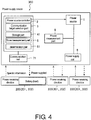
- a power measurement part 9 for measuring an output power of the power source 1 is further installed in the second embodiment. Further, the components similar to those in the first embodiment are marked with the same reference numbers used in the first embodiment and related descriptions thereof are omitted hereinafter.
- the power supply device 300 includes the power source 1, the power source controller 2, the communication target selection part 3, a storage part 41, a time measurement part 5, a determination part (controller) 61, a communication part 71, the power supply coil 8 and the power measurement part 9.
- the communication part 71 obtains specific information (e.g., addresses) from the power receiving devices 200.
- the power measurement part 9 measures the output power of the power source 1.
- the storage part 41 stores a measured variation pattern of the output power of the power source 1 in an elapsed time and a predicted variation pattern of the output power of the power source 1 in the elapsed time predicted in advance.
- the determination part 61 determines whether the measured variation pattern of the output power in the elapsed time is substantially identical to the predicted variation pattern of the output power in the elapsed time predicted in advance.
- the method for determining whether they are approximate or not may refer to the description in the first embodiment.
- a selection of the power receiving device 200 for breaking the communication made by the power supply device 300 of the second embodiment is described as follows.
- one of rules for determining whether to preferentially disconnect the communication or not is based on the reducing speed of the requested power of the power receiving device 200. For instance, among three communication break candidates, as shown by the equation (2a) of the second embodiment in FIG. 2 , when the requested power [W] is reduced in relative to time variation, the power receiving device having the requested power [W] first reached within a fixed value on the time T may be preferentially disconnected.
- the fixed value may be 1W or 0W. Said fixed value may also be appropriately adjusted according to characteristic or actual charging requirement of the power receiving device 200.
- step S21 a power is provided to the power supply coil 8 (referring to FIG. 4 ).
- step S22 an elapsed time counted from the time when starting to supply the power is measured.
- step S23 specific information (e.g., addresses) is obtained from the power receiving device 200.
- step S24 an output power of the power source 1 is measured.
- step S25 a result of the output power obtained in step S24 is stored in the storage part 41 and plotted at intervals of the elapsed time.
- step S26 whether the plotted results obtained in step S25 are increased for a fixed time and subsequently decreased for another fixed time is determined. If yes, the process proceeds to step S27, and otherwise returns to step S24.
- step S27 whether the plotted results (measured variation pattern) starting from 0 to Tymax (referring to FIG. 3 ) in the elapsed time are substantially identical to the predicted variation pattern of the output power stored in the storage part 41 is determined. If the result is substantially identical, the process proceeds to step S28, and otherwise proceeds to step S30.
- step S28 whether the plotted results after the time point Tymax in the elapsed time are substantially identical to the predicted variation pattern of the output power stored in the storage part 41 is determined. If the result is substantially identical, the process proceeds to step S29, and otherwise proceeds to step S30.
- step S29 the corresponding power receiving device 200 is treated as a communication break candidate.
- step S30 the corresponding power receiving device 200 is not treated as the communication break candidate.
- step S31 whether a quantity of the communication break candidate is one is determined. If the quantity of the communication break candidate is two or more, the process proceeds to step S32.
- step S32 a maximum operating voltage of each of the power receiving devices 200 treated as the communication break candidate is obtained.
- step S33 the power receiving device 200 having a largest difference between the maximum operating voltage obtained in step S32 and the received voltage among the power receiving devices 200 is treated as the communication break candidate.
- step S32 to S33 in order to prevent an unchargeable issue of the power receiving device 200 caused by the received voltage being less than a minimum operating voltage, the minimum operating voltage of each of the power receiving devices 200 being the communication break candidate is obtained and the power receiving devices 200 having a largest difference between the minimum operating voltage and the received voltage of the power receiving device 200 is treated as a communication break candidate.
- the determination part 61 determines whether the measured variation pattern of the output power (output information) of the power source 1 in the elapsed time is approximate to the predicted variation pattern of the output power of the power source 1 in the elapsed time, and preferentially disconnect the power receiving device 200 determined as being approximate. Accordingly, the variation of the output power of the power source 1 becomes predictable in the elapsed time once the measured variation pattern of the output power of the power source 1 in the elapsed time is approximate to the predicted variation pattern of the output power of the power source 1 in the elapsed time.
- the number of the power receiving devices 200 that the communication part 71 communicates with may be prevented from exceeding the predetermined number of the power receiving devices 200 that the communication part 71 is capable of communicating with, and the power may be properly supplied. Further, since the power receiving device 200 treated as the communication break candidate is directly determined by checking the output power of the power source 1, it is not required to obtain information such as the received power of the power receiving device 200 so the overall operation may be simplified.
- the determination part 6 determines that the measured variation pattern is approximate to the predicted variation pattern when the measured variation pattern of the output power in the elapsed time is substantially identical to the predicted variation pattern of the output power continuously increased for the fixed time and subsequently decreased for the another fixed time. Accordingly, whether the power receiving device 200 is the power receiving device 200 having the battery that can be stably charged for more than the fixed time through the cccv control may be determined. Also, if the measured variation pattern is determined as being approximate to the predicted variation pattern, the variation of the output power of the power source 1 becomes predictable in the elapsed time. Therefore, the power may still be properly supplied even if the predictable power receiving device 200 is disconnected.
- the second embodiment can also provide other effects similar to those of the first embodiment.
- a power supply device 400 according to the third embodiment of the invention is described as follows.
- power receiving devices 500 not including the battery e.g., a light emitting diode (LED) lighting
- a predicted variation pattern of a requested power of the power receiving device 500 in an elapsed time includes a variation pattern of the requested power showed no variation for more than a fixed time.
- the components similar to those in the first embodiment are marked with the same reference numbers used in the first embodiment and related descriptions thereof are omitted hereinafter.
- the power supply device 400 includes the power source 1, the power source controller 2, the communication target selection part 3, a storage part 42, the time measurement part 5, the determination part (controller) 6, the communication part 7 and the power supply coil 8.
- a plurality of variation of the requested power in the elapsed time are stored as the predicted variation patterns.
- an equation (3) as shown in FIG. 7 is stored in the storage part 42 as a variation pattern of the requested power showed no variation over a fixed time (e.g., 1 hour).
- j is set as arbitrary constant (e.g., 1).
- y j
- the method for determining whether they are approximate or not may refer to the description in the first embodiment.
- the power receiving device having a longer power-supply elapsed time is preferentially disconnected.
- step S41 a power is provided the power supply coil 8 (referring to FIG. 6 ).
- step S42 an elapsed time counted from the time when starting to supply the power is measured.
- step S43 specific information (e.g., addresses) is obtained from the power receiving device 500.
- step S44 a received power is obtained from the power receiving device 500.
- step S45 a result of the received power obtained in step S44 is stored in the storage part 42 and plotted at intervals of the elapsed time.
- step S46 whether it is elapsed for more than a fixed time is determined. If yes, the process proceeds to step S47, and otherwise returns to step S44.
- step S47 whether the plotted results obtained in step S45 are substantially identical to the predicted variation pattern of the requested power stored in the storage part 42 is determined. If the result is substantially identical, the process proceeds to step S48, and otherwise proceeds to step S49.
- step S48 the corresponding power receiving device 500 is treated as a communication break candidate.
- step S49 the corresponding power receiving device 500 is not treated as the communication break candidate.
- step S50 whether a quantity of the communication break candidate is one is determined. If the quantity of the communication break candidate is two or more, the process proceeds to step S51.
- step S51 a maximum operating voltage of each of the power receiving devices 500 treated as the communication break candidate is obtained.
- step S52 the power receiving device 500 having a largest difference between the maximum operating voltage obtained in step S51 and the received voltage among the power receiving devices 500 is treated as the communication break candidate.
- step S51 to S55 in order to prevent an unchargeable issue of the power receiving device 500 caused by the received voltage being less than a minimum operating voltage, the minimum operating voltage of each of the power receiving devices 500 being the communication break candidate is obtained and the power receiving devices 500 having a largest difference between the minimum operating voltage and the received voltage of the power receiving device 500 is treated as a communication break candidate.
- the determination part 6 determines that the measured variation pattern is approximate to the predicted variation pattern when the measured variation pattern of the received power in the elapsed time is substantially identical to the predicted variation pattern of the request power showing no variation for more than the fixed time. Accordingly, whether the power receiving device 500 is the power receiving device 500 not having the battery may be determined. Also, if the measured variation pattern is determined to be approximate to the predicted variation pattern, the received power of the power receiving device 500 is predictable to show no variation in the elapsed time. Therefore, the power may still be stably supplied even if the predictable power receiving device 500 is disconnected.
- the third embodiment can also provide other effects similar to those of the first embodiment.
- a predicted variation pattern of a requested power of the power receiving device 201 in an elapsed time includes a variation pattern of the requested power continuously decreased for more than a fixed time.
- the components similar to those in the first embodiment are marked with the same reference numbers used in the first embodiment and related descriptions thereof are omitted hereinafter.
- the power supply device 101 includes the power source 1, the power source controller 2, the communication target selection part 3, a storage part 43, the time measurement part 5, the determination part (controller) 6, the communication part 7 and the power supply coil 8.
- a plurality of variation patterns such as the variation pattern of the requested power in the elapsed time are stored as the predicted variation pattern.
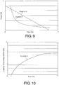
- an equation (4) and an equation (5) as shown in FIG. 9 are stored in the storage part 43 as a variation pattern of the requested power continuously decreased for more than the fixed time (e.g., 1 hour).
- k, 1, m and n are set as arbitrary constant (e.g., 1).
- y ⁇ k ⁇ x + 1
- y m x n
- the selection of the power receiving device 201 for breaking the communication performed by the power supply device 101 is identical to the selection described in the third embodiment shown in FIG. 8 .
- one of rules for determining whether to preferentially disconnect or not is based on the reducing speed of the requested power of the power receiving device 201. For instance, among three communication break candidates, as shown by the equation (5) of the second embodiment in FIG. 9 , when the requested power [W] is reduced in relative to time variation, the power receiving device having the requested power [W] first reached within a fixed value on the time T may be preferentially disconnected.
- the fixed value may be 1W or 0W. Said fixed value may also be appropriately adjusted according to characteristic or actual charging requirement of the power receiving device 201.
- the determination part 6 determines that the measured variation pattern is approximate to the predicted variation pattern when the measured variation pattern of the received power in the elapsed time is substantially identical to the predicted variation pattern of the received power continuously decreased for more than the fixed time. Accordingly, if the measured variation patter is determined to be approximate to the predicted variation pattern, the variation of the received power of the power receiving device 201 becomes predictable in the elapsed time. Therefore, the power may still be properly supplied even if the predictable power receiving device 201 is disconnected. Further, it may be determined that the power supply is no longer required after the requested power becomes zero so the power supply may be prevented from wasting.
- the fourth embodiment can also provide other effects similar to those of the first embodiment.
- a determination part 62 determines whether a measured variation pattern of a remaining capacity of a secondary battery of a power receiving device 202 in an elapsed time is approximate to a predicted variation pattern of the remaining capacity of the secondary battery in the elapsed time. Further, the components similar to those in the first embodiment are marked with the same reference numbers used in the first embodiment and related descriptions thereof are omitted hereinafter.
- the power supply device 102 includes the power source 1, the power source controller 2, the communication target selection part 3, a storage part 44, the time measurement part 5, the determination part (controller) 62, the communication part 7 and the power supply coil 8.
- a plurality of variation patterns such as the variation patterns of the remaining capacity of the secondary battery in the elapsed time are stored as the predicted variation patterns.
- an equation (6) as shown in FIG. 10 is stored in the storage part 44 as a variation pattern of the secondary battery saturated after a fixed time (e.g., 1 hour).
- the determination part 62 determines whether the measured variation pattern of the remaining capacity of the secondary battery of the power receiving device 202 in the elapsed time is substantially identical to the predicted variation pattern of the remaining capacity of the secondary battery of the power receiving device 202 in the elapsed time.
- o and p are set as arbitrary constant (e.g., 1).
- y o ⁇ log p x
- a selection of the power receiving device 202 for breaking the communication made by the power supply device 102 of the fifth embodiment is described as follows.
- the method for determining whether they are approximate or not may refer to the description in the first embodiment.
- the communication break candidates are determined according to the remaining capacity of the secondary battery of the power receiving device 202.
- the power receiving device 102 can receive a maximum capacity [Ah] of the secondary battery of the power receiving device 202 from the power receiving device 202 being the communication break candidate.
- the power receiving device having a smallest difference between the maximum capacity and a current capacity of the power receiving device may also be preferentially disconnected.
- the power supplying device 102 receives a charging condition (progress information) of the secondary battery of the power receiving device 202 from the power receiving device 202.
- the power supplying device 102 can preferentially disconnect the power receiving device 202 approaching a fully-charged state (100%) according to charging progress information obtained from the power receiving device 202.
- step S61 a power is provided to the power supply coil 8 (referring to FIG. 1 ).
- step S62 an elapsed time counted from the time when starting to supply the power is measured.
- step S63 specific information (e.g., addresses) is obtained from the power receiving device 202.
- step S64 a remaining capacity of a secondary battery is obtained from the power receiving device 202.
- step S65 a result of the remaining capacity of the secondary battery obtained in step S64 is stored in the storage part 44 (referring to FIG. 1 ) and plotted at intervals of the elapsed time.
- step S66 whether it is elapsed for more than a fixed time is determined. If yes, the process proceeds to step S67, and otherwise returns to step S64.
- step S67 whether the plotted results (measured variation pattern) obtained in step S65 are substantially identical to the predicted variation pattern of the remaining capacity of the secondary battery stored in the storage part 44 is determined. If the result is substantially identical, the process proceeds to step S68, and otherwise proceeds to step S69.
- step S68 the corresponding power receiving device 202 is treated as a communication break candidate.
- step S69 the corresponding power receiving device 202 is not treated as the communication break candidate.
- step S70 whether a quantity of the communication break candidate is one is determined. If the quantity of the communication break candidate is two or more, the process proceeds to step S71.
- step S71 a maximum operating voltage of each of the power receiving devices 202 treated as the communication break candidate is obtained.
- step S72 the power receiving device 202 having a largest difference between the maximum operating voltage obtained in step S71 and the received voltage among the power receiving devices 202 is treated as the communication break candidate.
- step S71 to S72 in order to prevent an unchargeable issue of the power receiving device 202 caused by the received voltage being less than the minimum operating voltage, the minimum operating voltage of each of the power receiving devices 202 being the communication break candidate is obtained and the power receiving device 202 having a largest difference between the minimum operation voltage and the received voltage of the power receiving devices 202 is treated as a communication break candidate.
- the determination part 62 determines that the measured variation pattern is approximate to the predicted variation pattern when the measured variation of the remaining capacity of the secondary battery in the elapsed time is substantially identical to the predicted variation pattern of the remaining capacity of the secondary battery saturated after the fixed time. Accordingly, if the measured variation pattern is determined to be approximate to the predicted variation pattern, the variation of the remaining capacity of the secondary battery of the power receiving device 202 becomes predictable in the elapsed time. Therefore, the power may still be properly supplied even if the predictable power receiving device 202 is disconnected. Further, since the power receiving device 202 treated as the communication break candidate is directly determined by checking the remaining capacity of the secondary battery of the power receiving device 202, the power may be supplied more accurately. Further, it may be determined that the power supply is no longer required after the remaining capacity of the secondary battery is saturated so the power supply may be prevented from wasting.
- the fifth embodiment can also provide other effects similar to those of the first embodiment.
- the smart phone is used as the power receiving device, but the invention is not limited thereto.
- a personal computer PC
- a tablet computer a digital camera and the like may also be used as the power receiving device.
- the received power is obtained from the power receiving device, but the invention is not limited thereto.
- a received voltage may also be obtained from the power receiving device.
- the output power is obtained from the power source, but the invention is not limited thereto.
- an output voltage may also be obtained from the power source.
- a quantity of the power supply coil installed in the power supply device is one, but the invention is not limited thereto.
- the quantity of the power supply coil may also be more than one.
- the measured variation pattern is determined to be approximate to the predicted variation pattern according to the absolute value of the plotted results, but the invention is not limited thereto.
- the measured variation pattern may be determined as being approximate to the predicted variation pattern according to a waveform shape of the plotted results.
- the predetermined number of the power receiving devices that the communication part is capable of communicating with is three, but the invention is not limited thereto.
- the predetermined number may also be four or more.
- the fixed time for observing the variations of the power and the remaining capacity of the secondary battery is 1 hour or 0.5 hour, but the invention is not limited thereto.
- the fixed time may also be a time other than 1 hour or 0.5 hour.
- the coefficients (i.e., a to p) of the equations for predicting the variation pattern are 1, but the invention is not limited thereto.
- the coefficients may also be a constant other than 1.
- the power receiving device having the largest difference between the maximum operating voltage and the received voltage is treated as the communication break candidate when the quantity of the communication break candidate is two or more, but the invention is not limited thereto.
- the power receiving device having a largest difference between the minimum operating voltage and the received voltage may also be treated as the communication break candidate.
- the first embodiment to the fifth embodiment are all described by using the example in which the variation patterns of the received power of the power receiving devices in the elapsed time are of the same type.
- the invention is also adapted to the case where all the variation patterns described in the first embodiment to the fifth embodiment coexist in the measured variation patterns of the communication break candidates being receiving power in the elapsed time.
- the received power showing no variation over time is selected to be preferentially disconnected.
- the communication break candidates include the power receiving device having the variation pattern relative to time variation as in the first, second, fourth and fifth embodiments as well as the power receiving device having the variation pattern showing no variation over time as in the third embodiment, the power receiving device having the variation pattern showing no variation as in the third embodiment is preferentially disconnected.
- operations of the controller in the invention are performing by using the flowchart of a flow driven type which performs the operations in sequence, but the invention is not limited thereto.
- the operations of the controller may also be performing by using an event driven type process which performs a corresponding operation each time when a specific event occurs. Nonetheless, the operations may be performed by completely using the event driven type process as well as using a combination of both the event driven type process and the flow driven type process.
Landscapes
- Engineering & Computer Science (AREA)
- Computer Networks & Wireless Communication (AREA)
- Power Engineering (AREA)
- Signal Processing (AREA)
- Charge And Discharge Circuits For Batteries Or The Like (AREA)
Abstract
Description
- The invention relates to a power supply device, and more particularly, relates to a power supply device having a communication part and a power supply method thereof.
- In the conventional art, a power supply device having a communication part and a power supply method has been proposed (e.g., referring to Patent Document 1).
- In
Patent Document 1, a wireless power device having communication channels is disclosed. Said wireless power device is disposed with the communication channels and a transmitting coil, and configured to supply a power from the transmitting coil to receiving coils of a plurality of receivers. Further, the communication channels are capable of wirelessly communicating with the receivers, respectively. Also, the communication channels are configured to transmit a signal for requesting correction of load resistance to the receivers. Further, the receivers are configured to correct the load resistances based on the signal requesting correction of the load resistance. As a result, the wireless power device is configured to control a power distribution for each of the receivers by making the receivers correct the load resistances in addition to supplying the power from the transmitting coil to the receiving coils of the receivers. - Patent Document 1:
Japanese Patent Publication No. 2014-54182 - In general, there is an upper limit for the number of the communication channels in terms of standard or specification. That is to say, the upper limit refers to a quantity (a number of units) that the communication channels are capable of simultaneously communicating with. For example, in Bluetooth™ standard, the upper limit is eight units at the most, but the upper limit may sometimes be less than eight units (e.g., 3 units) based on the specification. Therefore, when the power is supplied to the receivers having a number exceeding the number of the communication channels in the wireless power device according to
Patent Document 1, it is considered that the power may be supplied to the extra receiver before the signal requesting for correction of load resistance can arrive. - In this case, if the receiver not receiving the signal requesting for correction of load resistance has a smaller load resistance, it is considered that a receiving voltage value may become larger in correspondence to the smaller load resistance. On the other hand, if the receiver not receiving the signal requesting for correction of load resistance has a larger load resistance, it is considered that the receiving voltage value may become smaller in correspondence to the larger load resistance. As a result, it is considered that the receiving voltage value may sometimes become a value that falls outside a range acceptable by the receiver. Accordingly, the wireless power device in
Patent Document 1 may have a problem in which the wireless power device is unable to properly supply the power when the number of the receivers (power receiving devices) exceeds the number of units that the communication channels (communication part) are capable of simultaneously communicating with. - The invention is proposed to solve the above problem. The invention aims to provide a power supply device, which is capable of properly supplying the power even if the power is supplied to the power receiving devices (external device) having a number exceeding the number that the communication part is capable of simultaneously communicating with.
- A power supply device according to a first aspect of the invention includes: a power supply part, configured to be capable of supplying a power to a plurality of external devices; a communication part, configured to be capable of communicating with the external devices; and a controller, configured to disconnect one or more of the external devices based on a power supplied information of the external devices being in a predetermined range in a case that a number of requests for a communication from the external devices exceeds a number that the communication part is capable of communicating with at the same time. The power supply device can also have a power source for providing the power.
- The controller is configured to determine a disconnection based on a comparison of the power supplied information and predicted values of the power supplied information of the external devices.
- The power supplied information comprises a plurality of plotted results, and the controller is configured to decide to disconnect one or more of the external devices when a fixed ratio or more of the plotted results fall within a fixed range of the predicted values of the power supplied information.
- In the power supply device according to the first aspect of the invention, the variation of the power supplied information in the elapsed time becomes predictable after the controller compares the power supplied information and the predicted values of the power supplied information. Therefore, because of the predictable variation, one or more of the external devices not requiring the communication may be disconnected so the external devices requiring the communication may be preferentially connected. Also, by predicting the variation of the power supplied information in the elapsed time, the power may still be properly supplied even if the power is supplied to the external devices having a number exceeding the number that the communication part is capable of communicating with.
- Preferably, in the power supply device according to the first aspect of the invention, when a number of requests for the communication from the external devices exceeds a number that the communication part is capable of communicating with, one or more of the external devices will be decided to be disconnected by the controller. With such configuration, the number of the external devices that the communication part communicates with may be prevented from exceeding the predetermined number of the external devices that the communication part is capable of communicating with.
- Preferably, in the power supply device according to the first aspect of the invention, the communication part is configured to obtain power reception information from the external devices being communicated with. The power supplied information includes the power reception information of the external devices. With such configuration, the variation of the power reception information of the external devices becomes predictable in the elapsed time. Therefore, by disconnecting one or more of the predictable external devices, the number of the external devices that the communication part communicating with may be prevented from exceeding the predetermined number of the external devices that the communication part is capable of communicating with, and the power may be properly supplied to all of the external devices. Further, since the disconnection of the external devices is directly determined by checking the power reception information of the external devices, the power may be supplied more safely.
- Preferably, the variation of the power reception information of the external devices in the elapsed time herein includes a variation of a received power of the external devices in the elapsed time. The predicted values of the power reception information of the external devices in the elapsed time include a variation pattern of a requested power of the external devices in the elapsed time. With such configuration, the variation of the received power of the external devices becomes predictable in the elapsed time. Therefore, by disconnecting one or more of the predictable external devices, the number of the external devices that the communication part communicates with may be prevented from exceeding the predetermined number of the external devices that the communication part is capable of communicating with, and the power may be properly supplied to all of the external devices. Further, since the disconnection of the external devices is directly determined by checking the received power of the external devices, the power may be supplied more safely.
- Preferably, the predicted values includes a variation pattern continuously increased for a fixed time and subsequently decreased for another fixed time. With such configuration, whether one or more of the external devices includes a battery that can be stably charged for more than a fixed time through a cccv (constant current constant voltage) control may be determined. Also, the received power of the external devices becomes predictable in the elapsed time. Therefore, the power may still be properly supplied even if one or more of the predictable external devices are disconnected.
- Preferably, the predicted values includes a variation pattern of the requested power showing no variation for more than a fixed time. With such configuration, whether the external devices are the devices not having the battery may be determined. Also, the received power of the external devices is predictable to have no variation in the elapsed time. Therefore, the power may still be stably supplied even if one or more of the predictable external devices are disconnected.
- Preferably, the predicted values includes a variation pattern of the requested power continuously decreased for more than a fixed time. With such configuration, the received power of the external devices becomes predictable in the elapsed time. Therefore, the power may still be properly supplied even if one or more of the predictable external devices are disconnected. Further, it may be determined that the power supply is no longer required after the requested power becomes zero so the power supply may be prevented from wasting.
- Preferably, the power reception information includes a remaining capacity of a secondary battery of the external devices. A predicted values of the remaining capacity of the secondary battery of the external devices in the elapsed time include a variation pattern of the remaining capacity of the secondary battery saturated after a fixed time. With such configuration, the variation of the remaining capacity of the secondary battery of the external devices becomes predictable in the elapsed time. Therefore, the power may still be properly supplied even if one or more of the predictable external devices are disconnected. Further, since the disconnection of the external devices is directly determined by checking the remaining capacity of the secondary battery of the external devices, the power may be supplied more accurately. Further, it may be determined that the power supply is no longer required after the remaining capacity of the secondary battery is saturated so the power supply may be prevented from wasting.
- Preferably, in the power supply device according to the first aspect, the power supplied information includes output information of the power source. With such configuration, the variation of the output information of the power source becomes predictable in the elapsed time. Therefore, by disconnecting one or more of the predictable external devices, the number of the external devices that the communication part communicates with may be prevented from exceeding the predetermined number of the external devices that the communication part is capable of communicating with, and the power may be properly supplied to all of the external devices. Further, since the disconnection of the external devices is directly determined by checking the output information of the power source, it is not required to obtain the power reception information of the power source so the overall operation may be simplified.
- Preferably, the output information of the power source herein includes an output power of the power source. With such configuration, the variation of the output power of the power source becomes predictable in the elapsed time. Therefore, by disconnecting one or more of the predictable external devices, the number of the external devices that the communication part communicates with may be prevented from exceeding the predetermined number of the external devices that the communication part is capable of communicating with, and the power may be properly supplied. Further, since the disconnection of one or more of the external devices is directly determined by checking the output power of the power source, it is not required to obtain information such as the received power of the power source so the overall operation may be simplified. In addition, since the determination is made according to the power in the power supply device, the power may be determined more accurately without suffering external influences during the communication.
- In the power supply device, the predicted values includes a variation pattern of the output power continuously increased for a fixed time and subsequently decreased for another fixed time. With such configuration, whether one or more of the external devices are the devices having the battery that can be stably charged for more than the fixed time through the cccv control may be determined. Also, the variation of the output power of the power source becomes predictable in the elapsed time. Therefore, the power may still be properly supplied even if one or more of the predictable external devices are disconnected.
- According to the invention, as described above, the power may still be properly supplied even if the power is supplied to the external devices having a number exceeding the number that the communication part is capable of communicating with.
- The controller is configured to disconnect one or more of the external devices having a largest difference between a minimum operating voltage and a received voltage of the external devices.
- The controller is configured to disconnect one or more of the external devices whose requested power first reached within a fixed value among the external devices.
- The controller is configured to disconnect one or more of the external devices having a longer power-supply elapsed time among the external devices.
- The accompanying drawings are included to provide a further understanding of the invention, and are incorporated in and constitute a part of this specification. The drawings illustrate embodiments of the invention and, together with the description, serve to explain the principles of the invention.
-
FIG. 1 is a block diagram illustrating overall configuration of the power supply device in the first embodiment, the fourth embodiment and the fifth embodiment of the invention. -
FIG. 2 is a graph illustrating variation patterns of the requested power of the power receiving device (external device) and the output power of the power supply device over time in the first embodiment and the second embodiment of the invention. -
FIG. 3 is a flowchart illustrating a process in a selection of the power receiving device for breaking the communication according to the first embodiment of the invention. -
FIG. 4 is a block diagram illustrating overall configuration of the power supply device in the second embodiment of the invention. -
FIG. 5 is a flowchart illustrating a process in a selection of the power receiving device for breaking the communication according to the second embodiment of the invention. -
FIG. 6 is a block diagram illustrating overall configuration of the power supply device in the third embodiment of the invention. -
FIG. 7 is a graph illustrating a variation pattern of the requested power of the power receiving device over time in the third embodiment of the invention. -
FIG. 8 is flowchart illustrating a process in a selection of the power receiving device for breaking the communication according to the third embodiment and the fourth embodiment of the invention. -
FIG. 9 is a graph illustrating a variation pattern of the requested power of the power receiving device over time in the fourth embodiment of the invention. -
FIG. 10 is a graph illustrating a variation pattern of a remaining capacity of a secondary battery of the power receiving device over time in the firth embodiment of the invention. -
FIG. 11 is a flowchart illustrating a process in a selection of the power receiving device for breaking the communication according to the fifth embodiment of the invention. - Reference will now be made in detail to the present preferred embodiments of the invention, examples of which are illustrated in the accompanying drawings. Wherever possible, the same reference numbers are used in the drawings and the description to refer to the same or like parts.
- The embodiments of the invention are described below with reference to the accompanying drawings.
- Referring to
FIG. 1 to FIG. 3 , the configuration of a power supply device 100 according to the first embodiment of the invention is described as follows. As shown inFIG. 1 , the power supply device 100 of the first embodiment simultaneously supplies a power to a plurality of power receiving devices 200 (e.g., smart phones) disposed near the power supply device 100 in a magnetic resonance manner (used as a non-contact power supply device or a non-contact point power supply device) without disposing any wires or contact points between the power supply device 100 and the power receiving devices 200. - As shown in
FIG. 1 , the power supply device 100 includes apower source 1, apower source controller 2, a communicationtarget selection part 3, astorage part 4, atime measurement part 5, a determination part (controller) 6, acommunication part 7 and apower supply coil 8. - The
power supply coil 8 supplies a power provided from thepower source 1 to the power receiving devices 200. Thecommunication part 7 is capable of communicating with a predetermined number of the power receiving devices 200. Further, thecommunication part 7 obtains specific information (e.g., addresses) of the power receiving devices 200 and a received power of the power receiving device 200 selected by the communicationtarget selection part 3. Thetime measurement part 5 measures an elapsed time counted from the time when starting to supply the power. Thestorage part 4 stores a measured variation pattern of the received power from the selected power receiving device 200 in the elapsed time and a predicted variation pattern of a request power of the power receiving device 200 in the elapsed time in advance. Thedetermination part 6 determines whether the measured variation pattern of the received power in the elapsed time is substantially identical to the predicted variation pattern of the request power in the elapsed time. The power receiving device 200 corresponding to the measured variation pattern determined as being approximate to the predicted variation pattern is also treated as being approximate. In addition, definition of the so-call communication mentioned in the present application refers to a configuration capable of receiving and transmitting information related to the received power at the same time. - In the
storage part 4, a plurality of predicted variation patterns such as 10 or more predicted variation patterns of a requested power in the elapsed time are stored in advance. For example, equations (1), (1a), (1b) and (1c) shown inFIG. 2 are stored in thestorage part 4 as an expression for representing a variation pattern of the power continuously increased for a fixed time (e.g., 1 hour) by a constant current charging. Further, equations (2) and (2a) are stored in thestorage part 4 as an expression for representing a variation pattern of the power decreased for a fixed time (e.g., 0.5 hour) by a constant voltage charging. Furthermore, inFIG. 2 , a time-point where the constant current charging is switched to the constant voltage charging is set as Tymax, and the requested power at the time is set as ymax. Moreover, a, b, c, d, e, f, g, h, and i are set as arbitrary constant (e.g., 1).


- Here, in the first embodiment, when a number of requests for the communication from the power receiving devices 200 exceeds a number that the
communication part 7 is capable of simultaneously communicating with, the power receiving device 200 determined as being approximate by thedetermination part 6 is preferentially disconnected. Specifically, first of all, the variation of the received power of the selected power receiving device 200 in the elapsed time is plotted at intervals of the fixed time to obtain a measured variation pattern (plotted results) of the power receiving device. Here, to ensure the correctness, the number of the plotted results is preferred to be as many as possible. For example, 100 measured values are plotted for the received power of the power receiving device 200 in the elapsed time. Here, 100 is merely an example, and persons skilled in the art may increase or decrease the number of the plotted results based on demands. - As an example, the obtained variation pattern (the measured variation pattern) is considered as being approximate to the variation pattern (a predicted variation pattern) stored in advance by the power supplying device 100 when the following conditions are met. First, the amount of information obtaining from the predicted variation pattern and the number of the plotted results should be more than a fixed number, for example, the number of the plotted results is more than 100 (or even more than that). Then, the measured values of the plotted results should fall within a fixed range of predicted values of the predicted variation pattern (e.g., within ±5%). Generally, as an example, absolute values of the measured values may be used. Furthermore, if the measured variation pattern is determined as substantially identical to the predicted variation pattern and a fixed ratio or more of the plotted results are substantially identical to the predicted variation pattern e.g., more than 90%, the measured variation pattern is determined as being approximate to the predicted variation pattern. The power receiving device 200 corresponding to the measured variation pattern determined as being approximate to the predicted pattern is also treated as being approximate.
- If the power supplying device 100 is received a request for the communication from a new power receiving device 200 when the power supplying device 100 is communicating with the power receiving devices 200 in an allowable number (e.g., three), the power supplying device 100 disconnects the power receiving device 200 determined as being approximate among the three by the
determination part 6 and preferentially connect the new power receiving device 200. One of the rules for determining whether to preferentially break the communication or not is based on a reducing speed of the requested power of the power receiving device 200. For instance, among three communication break candidates, as shown by the equation (2) of the first embodiment inFIG. 2 , when the requested power [W] is reduced in relative to time variation, the power receiving device having the requested power [W] first reached within a fixed value on a time T may be preferentially disconnected. Here, as an example, the fixed value may be 1W or 0W. Said fixed value may also be appropriately adjusted according to characteristic or actual charging requirement of the power receiving device 200. - (Selection of the power receiving device for breaking the communication) Next, referring to
FIG. 3 , a selection of the power receiving device 200 for breaking the communication made by the power supply device 100 of the first embodiment is described as follows. - First of all, in step S1, a power is provided to the power supply coil 8 (referring to
FIG. 1 ). - In step S2, an elapsed time counted from the time when starting to supply the power is measured.
- In step S3, specific information (e.g., addresses) is obtained from the power receiving device 200.
- In step S4, a received power is obtained from the power receiving device 200.
- In step S5, a result of the received power obtained in step S4 are stored in the
storage part 4 and plotted at intervals of the elapsed time. - In step S6, whether the plotted results obtained in step S5 are increased for a fixed time and subsequently decreased for another fixed time is determined. If yes, the process proceeds to step S7, and otherwise returns to step S4.
- In step S7, whether the plotted results (measured variation pattern) starting from 0 to Tymax in the elapsed time are substantially identical to the predicted variation pattern of the requested power stored in the
storage part 4 is determined. If the result is substantially identical, the process proceeds to step S8, and otherwise proceeds to step S10. - In step S8, whether the plotted results after the time point Tymax in the elapsed time is substantially identical to the predicted variation pattern of the requested power stored in the
storage part 4 is determined. If the result is substantially identical, the process proceeds to step S9, and otherwise proceeds to step S10. - In step S9, the corresponding power receiving device 200 is treated as a communication break candidate.
- In step S10, the corresponding power receiving device 200 is not treated as the communication break candidate.
- In step S11, whether a quantity of the communication break candidate is one is determined. If the quantity of the communication break candidate is two or more, the process proceeds to step S12.
- In step S12, a maximum operating voltage of each of the power receiving devices 200 treated as the communication break candidate is obtained.
- In step S13, in order to prevent a breakdown of the power receiving device 200 caused by the received voltage being greater than the maximum operating voltage, the power receiving device 200 having a largest difference between the maximum operating voltage of each of the power receiving devices 200 obtained in step S12 and the received voltage of the power receiving devices 200 is treated as the communication break candidate.
- In a modification example of step S12 to S13, in order to prevent an unchargeable issue of the power receiving device 200 caused by the received voltage being less than a minimum operating voltage, the minimum operating voltage of each of the power receiving devices 200 being the communication break candidate is obtained and the power receiving devices 200 having a largest difference between the minimum operating voltage and the received voltage of the power receiving device 200 is treated as a communication break candidate.
- Other than preventing the breakdown of the power receiving device by selecting the communication break candidate mentioned above, other protection measures may also be taken for the power receiving device 200 that could be suddenly disconnected. For instance, some of the power receiving devices 200 may include a built-in protection function (a power management circuit (PMU, etc.), which is capable of protecting the power receiving device 200 from receiving power more than a maximum operating voltage and/or over voltage during a charging process or when the charging process is started or the charging process is terminated. The power management circuit of these power receiving devices (e.g., a cell phone or other general electronics) may receive external commands to activate the protection function. For the power receiving devices having the protection function and capable of activating the protection function by utilizing the external commands, when the power supplying device 100 considers these power receiving devices 200 as the communication break candidate and intends to disconnect these power receiving devices, the external commands may be sent to the power receiving devices 200 before disconnection to activate their protection functions.
- The protection function of the power receiving device 200 is to, for example, utilize a switch structure to alternatively switch between short circuit and open circuit of a power receiving part (a power receiving coil) and the control part physically, so as to protect the power receiving device 200 from the breakdown. Further, a resonance circuit structure capable of adjusting component constants (capacitance or inductance constants), such as a variable capacitor formed by connecting multiple capacitors together to be alternatively switched, may also be used. By adjusting the component constants, a resonance frequency of the power receiving device may be adjusted to adjust the charging function, so as to accomplish the effectiveness of slowly detaching from the charging process.
- The following effects may be obtained according to the first embodiment.
- In the first embodiment, as described above, the
determination part 6 determines whether a measured variation pattern of power supplied information related to thepower supply coil 8 in the elapsed time is approximate to a predicted variation pattern of the power supplied information related to thepower supply coil 8 in the elapsed time. Accordingly, the variation of the power supplied information in the elapsed time becomes predictable after thedetermination part 6 determines the power supplied information related to thepower supply coil 8 as being approximate to the predicted variation pattern. Therefore, because of the predictable variation, the power receiving device 200 not requiring the communication may be disconnected so the power receiving device 200 requiring the communication may be preferentially connected. Also, the power may still be properly supplied even if the power is supplied to the power receiving devices 200 having a number exceeding the number that thecommunication part 7 is capable of simultaneously connecting to. - Further, in the first embodiment, as described above, when the number of requests for the communication from the power receiving devices 200 exceeds a number that the
communication part 7 is capable of simultaneously communicating with, the power receiving device 200 determined as being approximate by thedetermination part 6 is preferentially disconnected. Accordingly, because the power receiving device 200 determined as being approximate by thedetermination part 6 is preferentially disconnected, the number of the power receiving devices 200 that thecommunication part 7 communicates with may be prevented from exceeding the predetermined number that thecommunication part 7 is capable of communicating with. - Further, in the first embodiment, as described above, the
determination part 6 determines whether the measured variation pattern of the received power (power reception information) of the power receiving device 200 in the elapsed time obtained by thecommunication part 7 is approximate to the predicted variation pattern of the requested power (power reception information) of the power receiving device 200 in the elapsed time, and preferentially disconnect the power receiving device 200 determined as being approximate. Accordingly, the power receiving device 200 becomes predictable once the measured variation pattern of the received power of the power receiving device 200 in the elapsed time is approximate to the predicted variation pattern of the requested power of the power receiving device 200 in the elapsed time. Therefore, by disconnecting the predictable power receiving device 200, the number of the power receiving devices 200 that the being communicated with thecommunication part 7 may be prevented from exceeding the predetermined number that thecommunication part 7 is capable of communicating with, and the power may be properly supplied to all of the power receiving devices 200. Further, since the power receiving device 200 treated as the communication break candidate is directly determined by checking the received power of the power receiving device 200, the power may be supplied more safely. - Furthermore, in the first embodiment, as described above, the
determination part 6 can determine that the measured variation pattern is approximate to the predicted variation pattern when the measured variation pattern of the received power in the elapsed time is substantially identical to the predicted variation pattern of the requested power, which is continuously increased for the fixed time and subsequently decreased for the another fixed time. Accordingly, whether the power receiving device 200 includes a battery that can be stably charged for more than a fixed time through the cccv (constant current constant voltage) control may be determined. Also, if the measured variation pattern is determined to be approximate to the predicted variation pattern, the variation of the received power of the power receiving device 200 becomes predictable in the elapsed time. Therefore, the power may still be properly supplied even if the predictable power receiving device 200 is disconnected. - Next, referring to
FIG. 2 ,FIG. 4 andFIG. 5 , the configuration of apower supply device 300 according to the second embodiment of the invention is described as follows. In addition to the configuration described in the first embodiment, apower measurement part 9 for measuring an output power of thepower source 1 is further installed in the second embodiment. Further, the components similar to those in the first embodiment are marked with the same reference numbers used in the first embodiment and related descriptions thereof are omitted hereinafter. - As shown in
FIG. 4 , thepower supply device 300 includes thepower source 1, thepower source controller 2, the communicationtarget selection part 3, astorage part 41, atime measurement part 5, a determination part (controller) 61, acommunication part 71, thepower supply coil 8 and thepower measurement part 9. - The
communication part 71 obtains specific information (e.g., addresses) from the power receiving devices 200. Thepower measurement part 9 measures the output power of thepower source 1. Thestorage part 41 stores a measured variation pattern of the output power of thepower source 1 in an elapsed time and a predicted variation pattern of the output power of thepower source 1 in the elapsed time predicted in advance. Thedetermination part 61 determines whether the measured variation pattern of the output power in the elapsed time is substantially identical to the predicted variation pattern of the output power in the elapsed time predicted in advance. In addition, the method for determining whether they are approximate or not may refer to the description in the first embodiment. - Next, referring to
FIG. 5 , a selection of the power receiving device 200 for breaking the communication made by thepower supply device 300 of the second embodiment is described as follows. As similar to the first embodiment, one of rules for determining whether to preferentially disconnect the communication or not is based on the reducing speed of the requested power of the power receiving device 200. For instance, among three communication break candidates, as shown by the equation (2a) of the second embodiment inFIG. 2 , when the requested power [W] is reduced in relative to time variation, the power receiving device having the requested power [W] first reached within a fixed value on the time T may be preferentially disconnected. Here, as an example, the fixed value may be 1W or 0W. Said fixed value may also be appropriately adjusted according to characteristic or actual charging requirement of the power receiving device 200. - First of all, in step S21, a power is provided to the power supply coil 8 (referring to
FIG. 4 ). - In step S22, an elapsed time counted from the time when starting to supply the power is measured.
- In step S23, specific information (e.g., addresses) is obtained from the power receiving device 200.
- In step S24, an output power of the
power source 1 is measured. - In step S25, a result of the output power obtained in step S24 is stored in the
storage part 41 and plotted at intervals of the elapsed time. - In step S26, whether the plotted results obtained in step S25 are increased for a fixed time and subsequently decreased for another fixed time is determined. If yes, the process proceeds to step S27, and otherwise returns to step S24.
- In step S27, whether the plotted results (measured variation pattern) starting from 0 to Tymax (referring to
FIG. 3 ) in the elapsed time are substantially identical to the predicted variation pattern of the output power stored in thestorage part 41 is determined. If the result is substantially identical, the process proceeds to step S28, and otherwise proceeds to step S30. - In step S28, whether the plotted results after the time point Tymax in the elapsed time are substantially identical to the predicted variation pattern of the output power stored in the
storage part 41 is determined. If the result is substantially identical, the process proceeds to step S29, and otherwise proceeds to step S30. - In step S29, the corresponding power receiving device 200 is treated as a communication break candidate.
- In step S30, the corresponding power receiving device 200 is not treated as the communication break candidate.
- In step S31, whether a quantity of the communication break candidate is one is determined. If the quantity of the communication break candidate is two or more, the process proceeds to step S32.
- In step S32, a maximum operating voltage of each of the power receiving devices 200 treated as the communication break candidate is obtained.
- In step S33, the power receiving device 200 having a largest difference between the maximum operating voltage obtained in step S32 and the received voltage among the power receiving devices 200 is treated as the communication break candidate.
- In a modification example of step S32 to S33, in order to prevent an unchargeable issue of the power receiving device 200 caused by the received voltage being less than a minimum operating voltage, the minimum operating voltage of each of the power receiving devices 200 being the communication break candidate is obtained and the power receiving devices 200 having a largest difference between the minimum operating voltage and the received voltage of the power receiving device 200 is treated as a communication break candidate.
- The following effects may be obtained according to the second embodiment.
- In the second embodiment, as described above, the
determination part 61 determines whether the measured variation pattern of the output power (output information) of thepower source 1 in the elapsed time is approximate to the predicted variation pattern of the output power of thepower source 1 in the elapsed time, and preferentially disconnect the power receiving device 200 determined as being approximate. Accordingly, the variation of the output power of thepower source 1 becomes predictable in the elapsed time once the measured variation pattern of the output power of thepower source 1 in the elapsed time is approximate to the predicted variation pattern of the output power of thepower source 1 in the elapsed time. Therefore, by disconnecting the predictable power receiving device 200, the number of the power receiving devices 200 that thecommunication part 71 communicates with may be prevented from exceeding the predetermined number of the power receiving devices 200 that thecommunication part 71 is capable of communicating with, and the power may be properly supplied. Further, since the power receiving device 200 treated as the communication break candidate is directly determined by checking the output power of thepower source 1, it is not required to obtain information such as the received power of the power receiving device 200 so the overall operation may be simplified. - Furthermore, in the second embodiment, as described above, the
determination part 6 determines that the measured variation pattern is approximate to the predicted variation pattern when the measured variation pattern of the output power in the elapsed time is substantially identical to the predicted variation pattern of the output power continuously increased for the fixed time and subsequently decreased for the another fixed time. Accordingly, whether the power receiving device 200 is the power receiving device 200 having the battery that can be stably charged for more than the fixed time through the cccv control may be determined. Also, if the measured variation pattern is determined as being approximate to the predicted variation pattern, the variation of the output power of thepower source 1 becomes predictable in the elapsed time. Therefore, the power may still be properly supplied even if the predictable power receiving device 200 is disconnected. - Moreover, the second embodiment can also provide other effects similar to those of the first embodiment.
- Next, referring to
FIG. 6 and FIG. 7 , the configuration of apower supply device 400 according to the third embodiment of the invention is described as follows. Unlike the first embodiment,power receiving devices 500 not including the battery (e.g., a light emitting diode (LED) lighting) are provided in the third embodiment instead. A predicted variation pattern of a requested power of thepower receiving device 500 in an elapsed time includes a variation pattern of the requested power showed no variation for more than a fixed time. Further, the components similar to those in the first embodiment are marked with the same reference numbers used in the first embodiment and related descriptions thereof are omitted hereinafter. - As shown in
FIG. 6 , thepower supply device 400 includes thepower source 1, thepower source controller 2, the communicationtarget selection part 3, astorage part 42, thetime measurement part 5, the determination part (controller) 6, thecommunication part 7 and thepower supply coil 8. - In the
storage part 42, a plurality of variation of the requested power in the elapsed time are stored as the predicted variation patterns. For example, an equation (3) as shown inFIG. 7 is stored in thestorage part 42 as a variation pattern of the requested power showed no variation over a fixed time (e.g., 1 hour). Moreover, j is set as arbitrary constant (e.g., 1).
- Next, referring to
FIG. 8 , a selection of thepower receiving device 500 for breaking the communication made by thepower supply device 400 of the third embodiment is described as follows. In addition, the method for determining whether they are approximate or not may refer to the description in the first embodiment. When all the communication break candidates are thepower receiving device 500 having the variation pattern showing no variation over time as described in the third embodiment, the power receiving device having a longer power-supply elapsed time is preferentially disconnected. - First of all, in step S41, a power is provided the power supply coil 8 (referring to
FIG. 6 ). - In step S42, an elapsed time counted from the time when starting to supply the power is measured.
- In step S43, specific information (e.g., addresses) is obtained from the
power receiving device 500. - In step S44, a received power is obtained from the
power receiving device 500. - In step S45, a result of the received power obtained in step S44 is stored in the
storage part 42 and plotted at intervals of the elapsed time. - In step S46, whether it is elapsed for more than a fixed time is determined. If yes, the process proceeds to step S47, and otherwise returns to step S44.
- In step S47, whether the plotted results obtained in step S45 are substantially identical to the predicted variation pattern of the requested power stored in the
storage part 42 is determined. If the result is substantially identical, the process proceeds to step S48, and otherwise proceeds to step S49. - In step S48, the corresponding
power receiving device 500 is treated as a communication break candidate. - In step S49, the corresponding
power receiving device 500 is not treated as the communication break candidate. - In step S50, whether a quantity of the communication break candidate is one is determined. If the quantity of the communication break candidate is two or more, the process proceeds to step S51.
- In step S51, a maximum operating voltage of each of the
power receiving devices 500 treated as the communication break candidate is obtained. - In step S52, the
power receiving device 500 having a largest difference between the maximum operating voltage obtained in step S51 and the received voltage among thepower receiving devices 500 is treated as the communication break candidate. - In a modification example of step S51 to S55, in order to prevent an unchargeable issue of the
power receiving device 500 caused by the received voltage being less than a minimum operating voltage, the minimum operating voltage of each of thepower receiving devices 500 being the communication break candidate is obtained and thepower receiving devices 500 having a largest difference between the minimum operating voltage and the received voltage of thepower receiving device 500 is treated as a communication break candidate. - The following effects may be obtained according to the third embodiment.
- In the third embodiment, as described above, the
determination part 6 determines that the measured variation pattern is approximate to the predicted variation pattern when the measured variation pattern of the received power in the elapsed time is substantially identical to the predicted variation pattern of the request power showing no variation for more than the fixed time. Accordingly, whether thepower receiving device 500 is thepower receiving device 500 not having the battery may be determined. Also, if the measured variation pattern is determined to be approximate to the predicted variation pattern, the received power of thepower receiving device 500 is predictable to show no variation in the elapsed time. Therefore, the power may still be stably supplied even if the predictablepower receiving device 500 is disconnected. - Moreover, the third embodiment can also provide other effects similar to those of the first embodiment.
- Next, referring to
FIG. 1 ,FIG. 8 andFIG. 9 , the configuration of a power supply device 101 according to the fourth embodiment of the invention is described as follows. Unlike the first embodiment, in the fourth embodiment, a predicted variation pattern of a requested power of the power receiving device 201 in an elapsed time includes a variation pattern of the requested power continuously decreased for more than a fixed time. Further, the components similar to those in the first embodiment are marked with the same reference numbers used in the first embodiment and related descriptions thereof are omitted hereinafter. - As shown in
FIG. 1 , the power supply device 101 includes thepower source 1, thepower source controller 2, the communicationtarget selection part 3, a storage part 43, thetime measurement part 5, the determination part (controller) 6, thecommunication part 7 and thepower supply coil 8. - In the storage part 43, a plurality of variation patterns such as the variation pattern of the requested power in the elapsed time are stored as the predicted variation pattern. For example, an equation (4) and an equation (5) as shown in
FIG. 9 are stored in the storage part 43 as a variation pattern of the requested power continuously decreased for more than the fixed time (e.g., 1 hour). Moreover, k, 1, m and n are set as arbitrary constant (e.g., 1).

- The selection of the power receiving device 201 for breaking the communication performed by the power supply device 101 is identical to the selection described in the third embodiment shown in
FIG. 8 . As similar to the first and second embodiments, one of rules for determining whether to preferentially disconnect or not is based on the reducing speed of the requested power of the power receiving device 201. For instance, among three communication break candidates, as shown by the equation (5) of the second embodiment inFIG. 9 , when the requested power [W] is reduced in relative to time variation, the power receiving device having the requested power [W] first reached within a fixed value on the time T may be preferentially disconnected. Here, as an example, the fixed value may be 1W or 0W. Said fixed value may also be appropriately adjusted according to characteristic or actual charging requirement of the power receiving device 201. - The following effects may be obtained according to the fourth embodiment.
- In the fourth embodiment, as described above, the
determination part 6 determines that the measured variation pattern is approximate to the predicted variation pattern when the measured variation pattern of the received power in the elapsed time is substantially identical to the predicted variation pattern of the received power continuously decreased for more than the fixed time. Accordingly, if the measured variation patter is determined to be approximate to the predicted variation pattern, the variation of the received power of the power receiving device 201 becomes predictable in the elapsed time. Therefore, the power may still be properly supplied even if the predictable power receiving device 201 is disconnected. Further, it may be determined that the power supply is no longer required after the requested power becomes zero so the power supply may be prevented from wasting. - Moreover, the fourth embodiment can also provide other effects similar to those of the first embodiment.
- Next, referring to
FIG. 1 ,FIG. 10 andFIG. 11 , the configuration of a power supply device 102 according to the fifth embodiment of the invention is described as follows. Unlike the first embodiment, in the fifth embodiment, adetermination part 62 determines whether a measured variation pattern of a remaining capacity of a secondary battery of a power receiving device 202 in an elapsed time is approximate to a predicted variation pattern of the remaining capacity of the secondary battery in the elapsed time. Further, the components similar to those in the first embodiment are marked with the same reference numbers used in the first embodiment and related descriptions thereof are omitted hereinafter. - As shown in
FIG. 1 , the power supply device 102 includes thepower source 1, thepower source controller 2, the communicationtarget selection part 3, a storage part 44, thetime measurement part 5, the determination part (controller) 62, thecommunication part 7 and thepower supply coil 8. - In the storage part 44, a plurality of variation patterns such as the variation patterns of the remaining capacity of the secondary battery in the elapsed time are stored as the predicted variation patterns. For example, an equation (6) as shown in
FIG. 10 is stored in the storage part 44 as a variation pattern of the secondary battery saturated after a fixed time (e.g., 1 hour). Thedetermination part 62 determines whether the measured variation pattern of the remaining capacity of the secondary battery of the power receiving device 202 in the elapsed time is substantially identical to the predicted variation pattern of the remaining capacity of the secondary battery of the power receiving device 202 in the elapsed time. Moreover, o and p are set as arbitrary constant (e.g., 1).
- Next, referring to
FIG. 11 , a selection of the power receiving device 202 for breaking the communication made by the power supply device 102 of the fifth embodiment is described as follows. In addition, the method for determining whether they are approximate or not may refer to the description in the first embodiment. - In the fifth embodiment, the communication break candidates are determined according to the remaining capacity of the secondary battery of the power receiving device 202. In another embodiment, when all the power receiving devices 202 treated as the communication break candidates have the measured variation pattern satisfying the predicted variation pattern of equation (6), the power receiving device 102 can receive a maximum capacity [Ah] of the secondary battery of the power receiving device 202 from the power receiving device 202 being the communication break candidate. In this case, the power receiving device having a smallest difference between the maximum capacity and a current capacity of the power receiving device may also be preferentially disconnected.
- In yet another embodiment, the power supplying device 102 receives a charging condition (progress information) of the secondary battery of the power receiving device 202 from the power receiving device 202. In this case, the power supplying device 102 can preferentially disconnect the power receiving device 202 approaching a fully-charged state (100%) according to charging progress information obtained from the power receiving device 202.
- First of all, in step S61, a power is provided to the power supply coil 8 (referring to
FIG. 1 ). - In step S62, an elapsed time counted from the time when starting to supply the power is measured.
- In step S63, specific information (e.g., addresses) is obtained from the power receiving device 202.
- In step S64, a remaining capacity of a secondary battery is obtained from the power receiving device 202.
- In step S65, a result of the remaining capacity of the secondary battery obtained in step S64 is stored in the storage part 44 (referring to
FIG. 1 ) and plotted at intervals of the elapsed time. - In step S66, whether it is elapsed for more than a fixed time is determined. If yes, the process proceeds to step S67, and otherwise returns to step S64.
- In step S67, whether the plotted results (measured variation pattern) obtained in step S65 are substantially identical to the predicted variation pattern of the remaining capacity of the secondary battery stored in the storage part 44 is determined. If the result is substantially identical, the process proceeds to step S68, and otherwise proceeds to step S69.
- In step S68, the corresponding power receiving device 202 is treated as a communication break candidate.
- In step S69, the corresponding power receiving device 202 is not treated as the communication break candidate.
- In step S70, whether a quantity of the communication break candidate is one is determined. If the quantity of the communication break candidate is two or more, the process proceeds to step S71.
- In step S71, a maximum operating voltage of each of the power receiving devices 202 treated as the communication break candidate is obtained.
- In step S72, the power receiving device 202 having a largest difference between the maximum operating voltage obtained in step S71 and the received voltage among the power receiving devices 202 is treated as the communication break candidate.
- In a modification example of step S71 to S72, in order to prevent an unchargeable issue of the power receiving device 202 caused by the received voltage being less than the minimum operating voltage, the minimum operating voltage of each of the power receiving devices 202 being the communication break candidate is obtained and the power receiving device 202 having a largest difference between the minimum operation voltage and the received voltage of the power receiving devices 202 is treated as a communication break candidate.
- The following effects may be obtained according to the fifth embodiment.
- In the fifth embodiment, as described above, the
determination part 62 determines that the measured variation pattern is approximate to the predicted variation pattern when the measured variation of the remaining capacity of the secondary battery in the elapsed time is substantially identical to the predicted variation pattern of the remaining capacity of the secondary battery saturated after the fixed time. Accordingly, if the measured variation pattern is determined to be approximate to the predicted variation pattern, the variation of the remaining capacity of the secondary battery of the power receiving device 202 becomes predictable in the elapsed time. Therefore, the power may still be properly supplied even if the predictable power receiving device 202 is disconnected. Further, since the power receiving device 202 treated as the communication break candidate is directly determined by checking the remaining capacity of the secondary battery of the power receiving device 202, the power may be supplied more accurately. Further, it may be determined that the power supply is no longer required after the remaining capacity of the secondary battery is saturated so the power supply may be prevented from wasting. - Moreover, the fifth embodiment can also provide other effects similar to those of the first embodiment.
- It should be noted that, the embodiments in the disclosure are regarded as examples rather than limitations in all aspects. The scope of the invention is defined by appended claims instead of the descriptions in the embodiments, and includes any possible changes (modification examples) containing equivalent meanings in appended claims within the scope.
- For example, in the first embodiment, the second embodiment, the fourth embodiment and the fifth embodiment, the smart phone is used as the power receiving device, but the invention is not limited thereto. For instance, a personal computer (PC), a tablet computer, a digital camera and the like may also be used as the power receiving device.
- Further, in the first embodiment, the third embodiment and the fourth embodiment, the received power is obtained from the power receiving device, but the invention is not limited thereto. For instance, a received voltage may also be obtained from the power receiving device.
- Further, in the second embodiment, the output power is obtained from the power source, but the invention is not limited thereto. For instance, an output voltage may also be obtained from the power source.
- Further, in the first embodiment to the fifth embodiment, a quantity of the power supply coil installed in the power supply device is one, but the invention is not limited thereto. The quantity of the power supply coil may also be more than one.
- Further, in the first embodiment to the fifth embodiment, the measured variation pattern is determined to be approximate to the predicted variation pattern according to the absolute value of the plotted results, but the invention is not limited thereto. For instance, the measured variation pattern may be determined as being approximate to the predicted variation pattern according to a waveform shape of the plotted results.
- Further, in the first embodiment to the fifth embodiment, the predetermined number of the power receiving devices that the communication part is capable of communicating with is three, but the invention is not limited thereto. For instance, the predetermined number may also be four or more.
- Further, in the first embodiment to the fifth embodiment, the fixed time for observing the variations of the power and the remaining capacity of the secondary battery is 1 hour or 0.5 hour, but the invention is not limited thereto. For instance, the fixed time may also be a time other than 1 hour or 0.5 hour.
- Further, in the first embodiment to the fifth embodiment, the coefficients (i.e., a to p) of the equations for predicting the variation pattern are 1, but the invention is not limited thereto. The coefficients may also be a constant other than 1.
- Further, in the first embodiment to the fifth embodiment, the power receiving device having the largest difference between the maximum operating voltage and the received voltage is treated as the communication break candidate when the quantity of the communication break candidate is two or more, but the invention is not limited thereto. In this invention, in order to prevent the phenomenon in which the power receiving device 200 is uncharged due to the received voltage being lower than a minimum operating voltage, the power receiving device having a largest difference between the minimum operating voltage and the received voltage may also be treated as the communication break candidate.
- The first embodiment to the fifth embodiment are all described by using the example in which the variation patterns of the received power of the power receiving devices in the elapsed time are of the same type. The invention is also adapted to the case where all the variation patterns described in the first embodiment to the fifth embodiment coexist in the measured variation patterns of the communication break candidates being receiving power in the elapsed time. In such case, the received power showing no variation over time is selected to be preferentially disconnected. For instance, if the communication break candidates include the power receiving device having the variation pattern relative to time variation as in the first, second, fourth and fifth embodiments as well as the power receiving device having the variation pattern showing no variation over time as in the third embodiment, the power receiving device having the variation pattern showing no variation as in the third embodiment is preferentially disconnected.
- Further, in the first embodiment to the fifth embodiment, for convenience of explanation, operations of the controller in the invention are performing by using the flowchart of a flow driven type which performs the operations in sequence, but the invention is not limited thereto. In this invention, the operations of the controller may also be performing by using an event driven type process which performs a corresponding operation each time when a specific event occurs. Nonetheless, the operations may be performed by completely using the event driven type process as well as using a combination of both the event driven type process and the flow driven type process.
- It will be apparent to those skilled in the art that various modifications and variations can be made to the structure of the present invention without departing from the scope or spirit of the invention. In view of the foregoing, it is intended that the present invention cover modifications and variations of this invention provided they fall within the scope of the following claims and their equivalents.
-
- 1 :
- power source
- 2 :
- power source controller
- 3 :
- communication target selection part
- 4, 41, 42, 43, 44 :
- storage part
- 5 :
- time measurement part
- 6, 61, 62 :
- determination part
- 7, 71 :
- communication part
- 8 :
- power supply coil
- 9 :
- power measurement part
- 100, 101, 102, 300, 400 :
- power supply device
- 200, 201, 202, 500 :
- power receiving devices
- S1∼S13, S21∼S33, S41∼S52, S61∼S72 :
- steps
- Tymax :
- elapsed time
- ymax :
- requested power
Claims (15)
- A power supply device (100), characterized in that the power supply device (100) comprises:a power supply part (8), configured to be capable of supplying a power to a plurality of external devices (200);a communication part (7), configured to be capable of communicating with the external devices (200); anda controller (6), configured to disconnect one or more of the external devices (200) based on a power supplied information of the external devices (200) being in a predetermined range in a case that a number of requests for a communication from the external devices (200) exceeds a number that the communication part (7) is capable of communicating with at the same time.
- The power supply device (100) according to claim 1, characterized in that the controller (6) is configured to determine a disconnection based on a comparison of the power supplied information and predicted values of the power supplied information of the external devices (200).
- The power supplying device (100) according to claim 2, characterized in that
the power supplied information comprise a plurality of plotted results, and
the controller (6) is configured to decide to disconnect one or more of the external devices (200) when a fixed ratio or more of the plotted results fall within a fixed range of the predicted values of the power supplied information. - The power supplying device (100) according to claim 2, characterized in that
the communication part (7) is configured to obtain power reception information from the external devices (200) being communicated with,
the power supplied information comprises the power reception information of the external devices (200). - The power supplying device (100) according to claim 4, characterized in that
the power reception information comprises a received power of the external devices (200),
and the predicted values comprises a variation pattern of a requested power of the external devices (200) in an elapsed time. - The power supplying device (100) according to any one of claims 2-5, characterized in that
the predicted values comprises a variation pattern continuously increased for a fixed time and subsequently decreased for another fixed time. - The power supplying device (100) according to any one of claims 2-5, characterized in that
the predicted values comprises a variation pattern showing no variation for more than a fixed time. - The power supplying device (100) according to any one of claims 2-5, characterized in that
the predicted values comprises a variation pattern continuously decreased for more than a fixed time. - The power supplying device (100) according to any one of claims 4-8, characterized in that
the power reception information comprises a remaining capacity of a secondary battery of the external devices,
and the predicted values comprises a variation pattern of the remaining capacity of the secondary battery saturated after a fixed time. - The power supplying device (100) according to any one of claims 1 to 9, characterized in that the power supply device (100) comprises: a power source (1),
wherein the power supplied information comprises output information of the power source (1). - The power supplying device (100) according to claim 10, characterized in that
the output information of the power source (1) comprises an output power of the power source (1). - The power supplying device (100) according to claim 11, characterized in that
the predicted values comprises a variation pattern of the output power continuously increased for a fixed time and subsequently decreased for another fixed time. - The power supplying device (100) according to any one of claims 1 to 12, characterized in that
the controller (6) is configured to disconnect one or more of the external devices (200) having a largest difference between a minimum operating voltage and a received voltage of the external devices (200). - The power supplying device (100) according to claim 5 or 6, characterized in that
the controller (6) is configured to disconnect one or more of the external devices (200) whose requested power first reached within a fixed value among the external devices (200). - The power supplying device (100) according to claim 5 or 6, characterized in that
the controller (6) is configured to disconnect one or more of the external devices (200) having a longer power supplied elapsed time among the external devices (200).
Applications Claiming Priority (2)
| Application Number | Priority Date | Filing Date | Title |
|---|---|---|---|
| JP2015205320 | 2015-10-19 | ||
| JP2016175888A JP6737088B2 (en) | 2015-10-19 | 2016-09-08 | Power supply device |
Publications (2)
| Publication Number | Publication Date |
|---|---|
| EP3160009A1 true EP3160009A1 (en) | 2017-04-26 |
| EP3160009B1 EP3160009B1 (en) | 2018-05-09 |
Family
ID=57389169
Family Applications (1)
| Application Number | Title | Priority Date | Filing Date |
|---|---|---|---|
| EP16194306.3A Active EP3160009B1 (en) | 2015-10-19 | 2016-10-18 | Power supply device |
Country Status (3)
| Country | Link |
|---|---|
| US (1) | US10193399B2 (en) |
| EP (1) | EP3160009B1 (en) |
| CN (1) | CN106602740B (en) |
Citations (2)
| Publication number | Priority date | Publication date | Assignee | Title |
|---|---|---|---|---|
| US20120200158A1 (en) * | 2009-10-08 | 2012-08-09 | Hitachi, Ltd. | Wireless power transmission system and wireless power transmission apparatus |
| JP2014054182A (en) | 2010-04-23 | 2014-03-20 | Qualcomm Inc | Wireless power distribution among plural receivers |
Family Cites Families (5)
| Publication number | Priority date | Publication date | Assignee | Title |
|---|---|---|---|---|
| US9685791B2 (en) * | 2012-07-09 | 2017-06-20 | Sandisk Technologies Llc | Apparatus and method for controlling wireless power transfer to mobile devices |
| KR102003358B1 (en) * | 2013-03-22 | 2019-07-24 | 삼성전자주식회사 | Wireless power transmitter, wireless power receiver and method for controlling each thereof |
| JP2015133815A (en) * | 2014-01-10 | 2015-07-23 | 船井電機株式会社 | Power feeding device, power feeding method, and power receiving device |
| CN103944283B (en) * | 2014-04-23 | 2016-10-05 | 北京智谷睿拓技术服务有限公司 | Wireless energy transfer method and wireless energy send equipment |
| BR112017023029B1 (en) * | 2015-04-29 | 2022-11-01 | Koninklijke Philips N.V | TIME INTERVAL ALLOCATION METHOD, WIRELESS INDUCTIVE POWER TRANSMITTER AND WIRELESS INDUCTIVE POWER RECEIVER |
-
2016
- 2016-10-18 EP EP16194306.3A patent/EP3160009B1/en active Active
- 2016-10-19 US US15/297,144 patent/US10193399B2/en active Active
- 2016-10-19 CN CN201610910776.6A patent/CN106602740B/en active Active
Patent Citations (2)
| Publication number | Priority date | Publication date | Assignee | Title |
|---|---|---|---|---|
| US20120200158A1 (en) * | 2009-10-08 | 2012-08-09 | Hitachi, Ltd. | Wireless power transmission system and wireless power transmission apparatus |
| JP2014054182A (en) | 2010-04-23 | 2014-03-20 | Qualcomm Inc | Wireless power distribution among plural receivers |
Also Published As
| Publication number | Publication date |
|---|---|
| US20170110884A1 (en) | 2017-04-20 |
| CN106602740B (en) | 2019-06-25 |
| EP3160009B1 (en) | 2018-05-09 |
| US10193399B2 (en) | 2019-01-29 |
| CN106602740A (en) | 2017-04-26 |
Similar Documents
| Publication | Publication Date | Title |
|---|---|---|
| US11360532B2 (en) | Power supply apparatus and power receiving apparatus | |
| EP2768112B1 (en) | Apparatus and method for detecting foreign object in wireless power transmitting system | |
| US20210075244A1 (en) | Charging management chip for charging battery based on switching charging and direct charging, and operating method of charging management chip | |
| EP2827472B1 (en) | Non-contact power feeding apparatus and non-contact power feeding method | |
| US9804619B2 (en) | USB power supply apparatus | |
| US12113381B2 (en) | Electronic device for charging multiple batteries | |
| US20130038282A1 (en) | Power reception apparatus and power receiving method | |
| EP3373406A1 (en) | Charging control device | |
| JP2013153614A (en) | Charge control device with protective function, and battery pack | |
| KR20150001837A (en) | Power receiving control circuit, method for controlling wireless power receiving device, and electronic device | |
| EP2897251B1 (en) | Power Transfer Unit | |
| US20160087688A1 (en) | Electronic apparatus | |
| US20240223001A1 (en) | Power transfer method and electronic apparatus for executing power transfer method | |
| US10291081B2 (en) | Methods and devices for protection in wireless power systems | |
| KR101192010B1 (en) | System for controlling charging of battery and battery pack comprising the same | |
| US20180159377A1 (en) | Wireless power transmission device | |
| EP3093988A1 (en) | Circuit constant variable circuit | |
| EP3160009B1 (en) | Power supply device | |
| US9018901B2 (en) | Electrical power receiving apparatus and electrical power receiving method | |
| US12308666B2 (en) | Electronic device and method of outputting power control signal for wireless power reception in the electronic device | |
| EP4219097B1 (en) | Mobile robot, mobile manipulator, and method for controlling mobile robot | |
| KR102943632B1 (en) | Electronic device for wirelessly receiving power and method for operating thereof | |
| JP6737088B2 (en) | Power supply device | |
| JP2024146986A (en) | Secondary battery test device and secondary battery test system including the same | |
| JP2011099759A (en) | Electronic device |
Legal Events
| Date | Code | Title | Description |
|---|---|---|---|
| PUAI | Public reference made under article 153(3) epc to a published international application that has entered the european phase |
Free format text: ORIGINAL CODE: 0009012 |
|
| STAA | Information on the status of an ep patent application or granted ep patent |
Free format text: STATUS: THE APPLICATION HAS BEEN PUBLISHED |
|
| AK | Designated contracting states |
Kind code of ref document: A1 Designated state(s): AL AT BE BG CH CY CZ DE DK EE ES FI FR GB GR HR HU IE IS IT LI LT LU LV MC MK MT NL NO PL PT RO RS SE SI SK SM TR |
|
| AX | Request for extension of the european patent |
Extension state: BA ME |
|
| STAA | Information on the status of an ep patent application or granted ep patent |
Free format text: STATUS: REQUEST FOR EXAMINATION WAS MADE |
|
| 17P | Request for examination filed |
Effective date: 20171005 |
|
| RBV | Designated contracting states (corrected) |
Designated state(s): AL AT BE BG CH CY CZ DE DK EE ES FI FR GB GR HR HU IE IS IT LI LT LU LV MC MK MT NL NO PL PT RO RS SE SI SK SM TR |
|
| GRAP | Despatch of communication of intention to grant a patent |
Free format text: ORIGINAL CODE: EPIDOSNIGR1 |
|
| STAA | Information on the status of an ep patent application or granted ep patent |
Free format text: STATUS: GRANT OF PATENT IS INTENDED |
|
| RIC1 | Information provided on ipc code assigned before grant |
Ipc: H02J 50/80 20160101ALI20171115BHEP Ipc: H04W 52/02 20090101ALI20171115BHEP Ipc: H02J 50/12 20160101ALI20171115BHEP Ipc: H02J 50/40 20160101AFI20171115BHEP Ipc: H04B 5/00 20060101ALI20171115BHEP |
|
| INTG | Intention to grant announced |
Effective date: 20171127 |
|
| GRAS | Grant fee paid |
Free format text: ORIGINAL CODE: EPIDOSNIGR3 |
|
| GRAA | (expected) grant |
Free format text: ORIGINAL CODE: 0009210 |
|
| STAA | Information on the status of an ep patent application or granted ep patent |
Free format text: STATUS: THE PATENT HAS BEEN GRANTED |
|
| AK | Designated contracting states |
Kind code of ref document: B1 Designated state(s): AL AT BE BG CH CY CZ DE DK EE ES FI FR GB GR HR HU IE IS IT LI LT LU LV MC MK MT NL NO PL PT RO RS SE SI SK SM TR |
|
| REG | Reference to a national code |
Ref country code: GB Ref legal event code: FG4D |
|
| REG | Reference to a national code |
Ref country code: CH Ref legal event code: EP Ref country code: AT Ref legal event code: REF Ref document number: 998399 Country of ref document: AT Kind code of ref document: T Effective date: 20180515 |
|
| REG | Reference to a national code |
Ref country code: IE Ref legal event code: FG4D |
|
| REG | Reference to a national code |
Ref country code: DE Ref legal event code: R096 Ref document number: 602016002966 Country of ref document: DE |
|
| REG | Reference to a national code |
Ref country code: NL Ref legal event code: MP Effective date: 20180509 |
|
| REG | Reference to a national code |
Ref country code: LT Ref legal event code: MG4D |
|
| PG25 | Lapsed in a contracting state [announced via postgrant information from national office to epo] |
Ref country code: BG Free format text: LAPSE BECAUSE OF FAILURE TO SUBMIT A TRANSLATION OF THE DESCRIPTION OR TO PAY THE FEE WITHIN THE PRESCRIBED TIME-LIMIT Effective date: 20180809 Ref country code: FI Free format text: LAPSE BECAUSE OF FAILURE TO SUBMIT A TRANSLATION OF THE DESCRIPTION OR TO PAY THE FEE WITHIN THE PRESCRIBED TIME-LIMIT Effective date: 20180509 Ref country code: NO Free format text: LAPSE BECAUSE OF FAILURE TO SUBMIT A TRANSLATION OF THE DESCRIPTION OR TO PAY THE FEE WITHIN THE PRESCRIBED TIME-LIMIT Effective date: 20180809 Ref country code: ES Free format text: LAPSE BECAUSE OF FAILURE TO SUBMIT A TRANSLATION OF THE DESCRIPTION OR TO PAY THE FEE WITHIN THE PRESCRIBED TIME-LIMIT Effective date: 20180509 Ref country code: SE Free format text: LAPSE BECAUSE OF FAILURE TO SUBMIT A TRANSLATION OF THE DESCRIPTION OR TO PAY THE FEE WITHIN THE PRESCRIBED TIME-LIMIT Effective date: 20180509 Ref country code: LT Free format text: LAPSE BECAUSE OF FAILURE TO SUBMIT A TRANSLATION OF THE DESCRIPTION OR TO PAY THE FEE WITHIN THE PRESCRIBED TIME-LIMIT Effective date: 20180509 |
|
| PG25 | Lapsed in a contracting state [announced via postgrant information from national office to epo] |
Ref country code: LV Free format text: LAPSE BECAUSE OF FAILURE TO SUBMIT A TRANSLATION OF THE DESCRIPTION OR TO PAY THE FEE WITHIN THE PRESCRIBED TIME-LIMIT Effective date: 20180509 Ref country code: NL Free format text: LAPSE BECAUSE OF FAILURE TO SUBMIT A TRANSLATION OF THE DESCRIPTION OR TO PAY THE FEE WITHIN THE PRESCRIBED TIME-LIMIT Effective date: 20180509 Ref country code: GR Free format text: LAPSE BECAUSE OF FAILURE TO SUBMIT A TRANSLATION OF THE DESCRIPTION OR TO PAY THE FEE WITHIN THE PRESCRIBED TIME-LIMIT Effective date: 20180810 Ref country code: RS Free format text: LAPSE BECAUSE OF FAILURE TO SUBMIT A TRANSLATION OF THE DESCRIPTION OR TO PAY THE FEE WITHIN THE PRESCRIBED TIME-LIMIT Effective date: 20180509 Ref country code: HR Free format text: LAPSE BECAUSE OF FAILURE TO SUBMIT A TRANSLATION OF THE DESCRIPTION OR TO PAY THE FEE WITHIN THE PRESCRIBED TIME-LIMIT Effective date: 20180509 |
|
| REG | Reference to a national code |
Ref country code: AT Ref legal event code: MK05 Ref document number: 998399 Country of ref document: AT Kind code of ref document: T Effective date: 20180509 |
|
| PG25 | Lapsed in a contracting state [announced via postgrant information from national office to epo] |
Ref country code: EE Free format text: LAPSE BECAUSE OF FAILURE TO SUBMIT A TRANSLATION OF THE DESCRIPTION OR TO PAY THE FEE WITHIN THE PRESCRIBED TIME-LIMIT Effective date: 20180509 Ref country code: DK Free format text: LAPSE BECAUSE OF FAILURE TO SUBMIT A TRANSLATION OF THE DESCRIPTION OR TO PAY THE FEE WITHIN THE PRESCRIBED TIME-LIMIT Effective date: 20180509 Ref country code: AT Free format text: LAPSE BECAUSE OF FAILURE TO SUBMIT A TRANSLATION OF THE DESCRIPTION OR TO PAY THE FEE WITHIN THE PRESCRIBED TIME-LIMIT Effective date: 20180509 Ref country code: PL Free format text: LAPSE BECAUSE OF FAILURE TO SUBMIT A TRANSLATION OF THE DESCRIPTION OR TO PAY THE FEE WITHIN THE PRESCRIBED TIME-LIMIT Effective date: 20180509 Ref country code: CZ Free format text: LAPSE BECAUSE OF FAILURE TO SUBMIT A TRANSLATION OF THE DESCRIPTION OR TO PAY THE FEE WITHIN THE PRESCRIBED TIME-LIMIT Effective date: 20180509 Ref country code: RO Free format text: LAPSE BECAUSE OF FAILURE TO SUBMIT A TRANSLATION OF THE DESCRIPTION OR TO PAY THE FEE WITHIN THE PRESCRIBED TIME-LIMIT Effective date: 20180509 Ref country code: SK Free format text: LAPSE BECAUSE OF FAILURE TO SUBMIT A TRANSLATION OF THE DESCRIPTION OR TO PAY THE FEE WITHIN THE PRESCRIBED TIME-LIMIT Effective date: 20180509 |
|
| REG | Reference to a national code |
Ref country code: DE Ref legal event code: R097 Ref document number: 602016002966 Country of ref document: DE |
|
| PG25 | Lapsed in a contracting state [announced via postgrant information from national office to epo] |
Ref country code: IT Free format text: LAPSE BECAUSE OF FAILURE TO SUBMIT A TRANSLATION OF THE DESCRIPTION OR TO PAY THE FEE WITHIN THE PRESCRIBED TIME-LIMIT Effective date: 20180509 Ref country code: SM Free format text: LAPSE BECAUSE OF FAILURE TO SUBMIT A TRANSLATION OF THE DESCRIPTION OR TO PAY THE FEE WITHIN THE PRESCRIBED TIME-LIMIT Effective date: 20180509 |
|
| PLBE | No opposition filed within time limit |
Free format text: ORIGINAL CODE: 0009261 |
|
| STAA | Information on the status of an ep patent application or granted ep patent |
Free format text: STATUS: NO OPPOSITION FILED WITHIN TIME LIMIT |
|
| 26N | No opposition filed |
Effective date: 20190212 |
|
| PG25 | Lapsed in a contracting state [announced via postgrant information from national office to epo] |
Ref country code: SI Free format text: LAPSE BECAUSE OF FAILURE TO SUBMIT A TRANSLATION OF THE DESCRIPTION OR TO PAY THE FEE WITHIN THE PRESCRIBED TIME-LIMIT Effective date: 20180509 |
|
| REG | Reference to a national code |
Ref country code: BE Ref legal event code: MM Effective date: 20181031 |
|
| PG25 | Lapsed in a contracting state [announced via postgrant information from national office to epo] |
Ref country code: LU Free format text: LAPSE BECAUSE OF NON-PAYMENT OF DUE FEES Effective date: 20181018 Ref country code: MC Free format text: LAPSE BECAUSE OF FAILURE TO SUBMIT A TRANSLATION OF THE DESCRIPTION OR TO PAY THE FEE WITHIN THE PRESCRIBED TIME-LIMIT Effective date: 20180509 |
|
| REG | Reference to a national code |
Ref country code: IE Ref legal event code: MM4A |
|
| PG25 | Lapsed in a contracting state [announced via postgrant information from national office to epo] |
Ref country code: BE Free format text: LAPSE BECAUSE OF NON-PAYMENT OF DUE FEES Effective date: 20181031 |
|
| PG25 | Lapsed in a contracting state [announced via postgrant information from national office to epo] |
Ref country code: IE Free format text: LAPSE BECAUSE OF NON-PAYMENT OF DUE FEES Effective date: 20181018 Ref country code: FR Free format text: LAPSE BECAUSE OF NON-PAYMENT OF DUE FEES Effective date: 20181031 |
|
| PG25 | Lapsed in a contracting state [announced via postgrant information from national office to epo] |
Ref country code: AL Free format text: LAPSE BECAUSE OF FAILURE TO SUBMIT A TRANSLATION OF THE DESCRIPTION OR TO PAY THE FEE WITHIN THE PRESCRIBED TIME-LIMIT Effective date: 20180509 |
|
| PG25 | Lapsed in a contracting state [announced via postgrant information from national office to epo] |
Ref country code: MT Free format text: LAPSE BECAUSE OF NON-PAYMENT OF DUE FEES Effective date: 20181018 |
|
| PG25 | Lapsed in a contracting state [announced via postgrant information from national office to epo] |
Ref country code: TR Free format text: LAPSE BECAUSE OF FAILURE TO SUBMIT A TRANSLATION OF THE DESCRIPTION OR TO PAY THE FEE WITHIN THE PRESCRIBED TIME-LIMIT Effective date: 20180509 |
|
| PG25 | Lapsed in a contracting state [announced via postgrant information from national office to epo] |
Ref country code: PT Free format text: LAPSE BECAUSE OF FAILURE TO SUBMIT A TRANSLATION OF THE DESCRIPTION OR TO PAY THE FEE WITHIN THE PRESCRIBED TIME-LIMIT Effective date: 20180509 |
|
| REG | Reference to a national code |
Ref country code: CH Ref legal event code: PL |
|
| PG25 | Lapsed in a contracting state [announced via postgrant information from national office to epo] |
Ref country code: MK Free format text: LAPSE BECAUSE OF NON-PAYMENT OF DUE FEES Effective date: 20180509 Ref country code: CY Free format text: LAPSE BECAUSE OF FAILURE TO SUBMIT A TRANSLATION OF THE DESCRIPTION OR TO PAY THE FEE WITHIN THE PRESCRIBED TIME-LIMIT Effective date: 20180509 Ref country code: HU Free format text: LAPSE BECAUSE OF FAILURE TO SUBMIT A TRANSLATION OF THE DESCRIPTION OR TO PAY THE FEE WITHIN THE PRESCRIBED TIME-LIMIT; INVALID AB INITIO Effective date: 20161018 |
|
| PG25 | Lapsed in a contracting state [announced via postgrant information from national office to epo] |
Ref country code: LI Free format text: LAPSE BECAUSE OF NON-PAYMENT OF DUE FEES Effective date: 20191031 Ref country code: CH Free format text: LAPSE BECAUSE OF NON-PAYMENT OF DUE FEES Effective date: 20191031 Ref country code: IS Free format text: LAPSE BECAUSE OF FAILURE TO SUBMIT A TRANSLATION OF THE DESCRIPTION OR TO PAY THE FEE WITHIN THE PRESCRIBED TIME-LIMIT Effective date: 20180909 |
|
| GBPC | Gb: european patent ceased through non-payment of renewal fee |
Effective date: 20201018 |
|
| PG25 | Lapsed in a contracting state [announced via postgrant information from national office to epo] |
Ref country code: GB Free format text: LAPSE BECAUSE OF NON-PAYMENT OF DUE FEES Effective date: 20201018 |
|
| REG | Reference to a national code |
Ref country code: DE Ref legal event code: R081 Ref document number: 602016002966 Country of ref document: DE Owner name: MAXELL, LTD., OYAMAZAKI, JP Free format text: FORMER OWNER: FUNAI ELECTRIC CO., LTD., DAITO, OSAKA, JP Ref country code: DE Ref legal event code: R081 Ref document number: 602016002966 Country of ref document: DE Owner name: FUNAI ELECTRIC CO., LTD., DAITO, JP Free format text: FORMER OWNER: FUNAI ELECTRIC CO., LTD., DAITO, OSAKA, JP |
|
| REG | Reference to a national code |
Ref country code: DE Ref legal event code: R081 Ref document number: 602016002966 Country of ref document: DE Owner name: MAXELL, LTD., OYAMAZAKI, JP Free format text: FORMER OWNER: FUNAI ELECTRIC HOLDINGS CO., LTD., OSAKA, JP Ref country code: DE Ref legal event code: R081 Ref document number: 602016002966 Country of ref document: DE Owner name: FUNAI ELECTRIC CO., LTD., DAITO, JP Free format text: FORMER OWNER: FUNAI ELECTRIC HOLDINGS CO., LTD., OSAKA, JP |
|
| REG | Reference to a national code |
Ref country code: DE Ref legal event code: R081 Ref document number: 602016002966 Country of ref document: DE Owner name: MAXELL, LTD., OYAMAZAKI, JP Free format text: FORMER OWNER: FUNAI ELECTRIC CO., LTD., DAITO, OSAKA, JP |
|
| REG | Reference to a national code |
Ref country code: DE Ref legal event code: R082 Ref document number: 602016002966 Country of ref document: DE Representative=s name: DENNEMEYER & ASSOCIATES RECHTSANWALTSGESELLSCH, DE Ref country code: DE Ref legal event code: R082 Ref document number: 602016002966 Country of ref document: DE Representative=s name: DENNEMEYER & ASSOCIATES S.A., DE |
|
| REG | Reference to a national code |
Ref country code: DE Ref legal event code: R082 Ref document number: 602016002966 Country of ref document: DE Representative=s name: DENNEMEYER & ASSOCIATES RECHTSANWALTSGESELLSCH, DE |
|
| PGFP | Annual fee paid to national office [announced via postgrant information from national office to epo] |
Ref country code: DE Payment date: 20251021 Year of fee payment: 10 |