EP2768112B1 - Apparatus and method for detecting foreign object in wireless power transmitting system - Google Patents
Apparatus and method for detecting foreign object in wireless power transmitting system Download PDFInfo
- Publication number
- EP2768112B1 EP2768112B1 EP14153903.1A EP14153903A EP2768112B1 EP 2768112 B1 EP2768112 B1 EP 2768112B1 EP 14153903 A EP14153903 A EP 14153903A EP 2768112 B1 EP2768112 B1 EP 2768112B1
- Authority
- EP
- European Patent Office
- Prior art keywords
- wireless power
- foreign object
- current measurement
- current
- detected
- Prior art date
- Legal status (The legal status is an assumption and is not a legal conclusion. Google has not performed a legal analysis and makes no representation as to the accuracy of the status listed.)
- Active
Links
- 238000000034 method Methods 0.000 title claims description 22
- 238000005259 measurement Methods 0.000 claims description 129
- 238000001514 detection method Methods 0.000 claims description 33
- 230000005540 biological transmission Effects 0.000 claims description 19
- 230000006698 induction Effects 0.000 claims description 8
- 230000008878 coupling Effects 0.000 claims description 4
- 238000010168 coupling process Methods 0.000 claims description 4
- 238000005859 coupling reaction Methods 0.000 claims description 4
- 238000010586 diagram Methods 0.000 description 14
- 230000007423 decrease Effects 0.000 description 11
- 238000012546 transfer Methods 0.000 description 6
- 230000005672 electromagnetic field Effects 0.000 description 4
- 238000002474 experimental method Methods 0.000 description 4
- 238000011161 development Methods 0.000 description 2
- 230000005611 electricity Effects 0.000 description 2
- 230000004044 response Effects 0.000 description 2
- RYGMFSIKBFXOCR-UHFFFAOYSA-N Copper Chemical compound [Cu] RYGMFSIKBFXOCR-UHFFFAOYSA-N 0.000 description 1
- 238000005299 abrasion Methods 0.000 description 1
- 230000015556 catabolic process Effects 0.000 description 1
- 239000004020 conductor Substances 0.000 description 1
- 229910052802 copper Inorganic materials 0.000 description 1
- 239000010949 copper Substances 0.000 description 1
- 238000006731 degradation reaction Methods 0.000 description 1
- 238000013461 design Methods 0.000 description 1
- 238000007599 discharging Methods 0.000 description 1
- 230000000694 effects Effects 0.000 description 1
- 230000005684 electric field Effects 0.000 description 1
- 230000005674 electromagnetic induction Effects 0.000 description 1
- 238000004880 explosion Methods 0.000 description 1
- 230000004907 flux Effects 0.000 description 1
- 238000010438 heat treatment Methods 0.000 description 1
- 230000001771 impaired effect Effects 0.000 description 1
- 230000001939 inductive effect Effects 0.000 description 1
- 239000000463 material Substances 0.000 description 1
- 239000002184 metal Substances 0.000 description 1
- 229910052751 metal Inorganic materials 0.000 description 1
- 239000005300 metallic glass Substances 0.000 description 1
- 230000035699 permeability Effects 0.000 description 1
- 230000008569 process Effects 0.000 description 1
- 230000005855 radiation Effects 0.000 description 1
- 230000011664 signaling Effects 0.000 description 1
- 230000002269 spontaneous effect Effects 0.000 description 1
- 230000009466 transformation Effects 0.000 description 1
- 229910000859 α-Fe Inorganic materials 0.000 description 1
Images


Classifications
-
- H—ELECTRICITY
- H02—GENERATION; CONVERSION OR DISTRIBUTION OF ELECTRIC POWER
- H02J—CIRCUIT ARRANGEMENTS OR SYSTEMS FOR SUPPLYING OR DISTRIBUTING ELECTRIC POWER; SYSTEMS FOR STORING ELECTRIC ENERGY
- H02J50/00—Circuit arrangements or systems for wireless supply or distribution of electric power
- H02J50/60—Circuit arrangements or systems for wireless supply or distribution of electric power responsive to the presence of foreign objects, e.g. detection of living beings
-
- H—ELECTRICITY
- H02—GENERATION; CONVERSION OR DISTRIBUTION OF ELECTRIC POWER
- H02J—CIRCUIT ARRANGEMENTS OR SYSTEMS FOR SUPPLYING OR DISTRIBUTING ELECTRIC POWER; SYSTEMS FOR STORING ELECTRIC ENERGY
- H02J7/00—Circuit arrangements for charging or depolarising batteries or for supplying loads from batteries
- H02J7/02—Circuit arrangements for charging or depolarising batteries or for supplying loads from batteries for charging batteries from ac mains by converters
-
- G—PHYSICS
- G01—MEASURING; TESTING
- G01R—MEASURING ELECTRIC VARIABLES; MEASURING MAGNETIC VARIABLES
- G01R29/00—Arrangements for measuring or indicating electric quantities not covered by groups G01R19/00 - G01R27/00
- G01R29/08—Measuring electromagnetic field characteristics
- G01R29/0807—Measuring electromagnetic field characteristics characterised by the application
- G01R29/0814—Field measurements related to measuring influence on or from apparatus, components or humans, e.g. in ESD, EMI, EMC, EMP testing, measuring radiation leakage; detecting presence of micro- or radiowave emitters; dosimetry; testing shielding; measurements related to lightning
-
- H—ELECTRICITY
- H02—GENERATION; CONVERSION OR DISTRIBUTION OF ELECTRIC POWER
- H02J—CIRCUIT ARRANGEMENTS OR SYSTEMS FOR SUPPLYING OR DISTRIBUTING ELECTRIC POWER; SYSTEMS FOR STORING ELECTRIC ENERGY
- H02J50/00—Circuit arrangements or systems for wireless supply or distribution of electric power
- H02J50/10—Circuit arrangements or systems for wireless supply or distribution of electric power using inductive coupling
- H02J50/12—Circuit arrangements or systems for wireless supply or distribution of electric power using inductive coupling of the resonant type
-
- H—ELECTRICITY
- H02—GENERATION; CONVERSION OR DISTRIBUTION OF ELECTRIC POWER
- H02J—CIRCUIT ARRANGEMENTS OR SYSTEMS FOR SUPPLYING OR DISTRIBUTING ELECTRIC POWER; SYSTEMS FOR STORING ELECTRIC ENERGY
- H02J50/00—Circuit arrangements or systems for wireless supply or distribution of electric power
- H02J50/80—Circuit arrangements or systems for wireless supply or distribution of electric power involving the exchange of data, concerning supply or distribution of electric power, between transmitting devices and receiving devices
-
- H04B5/24—
-
- H04B5/79—
-
- H—ELECTRICITY
- H02—GENERATION; CONVERSION OR DISTRIBUTION OF ELECTRIC POWER
- H02J—CIRCUIT ARRANGEMENTS OR SYSTEMS FOR SUPPLYING OR DISTRIBUTING ELECTRIC POWER; SYSTEMS FOR STORING ELECTRIC ENERGY
- H02J7/00—Circuit arrangements for charging or depolarising batteries or for supplying loads from batteries
- H02J7/0029—Circuit arrangements for charging or depolarising batteries or for supplying loads from batteries with safety or protection devices or circuits
Definitions
- the present invention is related to wireless power transmission and more particularly, an apparatus and method for detecting a foreign object in a wireless power transmitting system.
- US 2012/175,967 A1 discloses transmitting power wirelessly by electromagnetic induction in which an electrical drive signal supplied to one or more primary coils changes from a first value to a second value.
- an external charger is used to charge portable terminals such as a mobile phone, notebook computer, and PDA by supplying electric energy (or electric power) thereto.
- portable terminals such as a mobile phone, notebook computer, and PDA
- Conventional portable terminals include battery cells storing supplied electric energy and a circuit intended for charging and discharging (providing electric energy to the portable terminals) the battery cells
- the electrical interface between the charger and battery cells, through which battery cells are charged with electric energy includes contacts; the contact-type electrical interface receives commercial electricity, transforms the electricity into voltage and currents relevant to the battery cells, and provides electric energy to the battery cells through the contacts of the corresponding battery cells.
- contact-type electrical interface may cause problems such as instant discharge due to a potential difference between contacts, abrasion and outbreak of fire due to foreign objects, spontaneous discharge, decrease of battery lifetime, and degradation of battery performance.
- a wireless power transmitting method is also called a contactless power transmitting method or no point-of-contact power transmitting method.
- a wireless power transmitting system comprises a wireless power transmitting apparatus providing electric energy through wireless power transmission and a wireless power receiving apparatus receiving electric energy provided wirelessly from the wireless power transmitting apparatus and charging battery cells by using the received electric energy.
- the contact-type electrical interface suffers little from obstacles disturbing battery charge, such as foreign objects.
- the contact-type electrical interface suffers little from obstacles disturbing battery charge, such as foreign objects.
- the wireless power transmitting system utilizing no-point-of-contact charge
- a foreign object such as a metallic part is located between the wireless power receiving apparatus and wireless power transmitting apparatus, smooth power transmission is impaired due to the foreign object, and at the same time, problems such as damage and explosion of the corresponding product due to overload and heating of the foreign object may be caused. Therefore, there need to be an apparatus and method for detecting foreign objects in a wireless power transmitting system.
- An object of the present invention is to provide an apparatus and method for detecting foreign objects in a wireless power transmitting system.
- Another object of the present invention is to provide an apparatus and method for detecting foreign objects based on a current induced in a primary coil of a wireless power transmitting system.
- a yet another object of the present invention is to provide an apparatus and method for performing an operation in response to detection of foreign objects in a wireless power transmitting system.
- a still another object of the present invention is to provide an apparatus and method for wireless power transmission equipped with a function of detecting foreign objects in a wireless power transmission system.
- a wireless power transmitting apparatus detecting foreign objects.
- the apparatus comprises a primary core block being coupled with a secondary core block installed in a wireless power receiving apparatus and transmitting wireless power to the wireless power receiving apparatus through magnetic induction or magnetic resonance; an electric driving unit applying an AC (Alternating Current) signal required for the primary core block to transmit the wireless power; a control unit being connected to the electric driving unit and generating a control signal for controlling the AC signal; and a current measurement unit measuring a current flowing into the primary core block and obtaining a current measurement value converted to a numeric value relevant for the control unit to analyze the current.
- AC Alternating Current
- the control unit may detect foreign objects coming between the wireless power transmitting apparatus and wireless power receiving apparatus by using a result of comparing the current measurement value with a reference value.
- a method for detecting foreign objects by a wireless power transmitting apparatus equipped with a primary core block comprises applying an AC signal required for transmitting wireless power to the primary core block; transmitting the wireless power to a wireless power receiving apparatus by coupling a secondary core block installed in the wireless power receiving apparatus with the primary core block through magnetic induction or magnetic resonance; obtaining a current measurement value by measuring a current flowing into the primary core block; and detecting foreign objects located between the wireless power transmitting apparatus and the wireless power receiving apparatus based on a result of comparing the current measurement value with a reference value.
- wireless power is used to denote the energy of arbitrary shape related to electric fields, magnetic fields, and electromagnetic fields transmitted from a transmitter to a receiver without employing physical electromagnetic conductors.
- the wireless power may be called a power signal and may indicate an oscillating magnetic flux enclosed by a primary and secondary coil.
- this document describes power transformation of a system intended to charge devices such as a mobile phone, cordless phone, iPod, MP3 player, and headset wirelessly.
- basic principles of wireless transfer of energy rely on magnetic inductive coupling, magnetic resonance coupling (namely, resonance induction) utilizing frequencies below 30 MHz, or both.
- LF magnetic resonance coupling
- HF 13.56 MHz
- FIG. 1 is a block diagram illustrating constituting elements of a wireless power transmitting system according to one embodiment of the present invention.
- a wireless power transmitting system 100 comprises a wireless power transmitting apparatus 110 and one wireless power receiving apparatus 150-1 or n wireless power receiving apparatuses 150-1, ..., 150-n.
- the wireless power transmitting apparatus 110 includes a primary core block.
- the primary core block may comprise a core and one or more primary coils 111.
- the wireless power transmitting apparatus 110 may have an arbitrary shape, but one of the preferred shapes is a flat platform with a power transmission surface; each wireless power receiving apparatus 150-1, ..., 150-n may be disposed on or around the platform.
- the wireless power receiving apparatus 150-1, ..., 150-n may be separated from the wireless power transmitting apparatus 110; each of the wireless power receiving apparatus 150-1, ..., 150-n is equipped with a secondary core block coupled with an electromagnetic field generated by the primary core block of the wireless power transmitting apparatus 110 in the vicinity thereof.
- the secondary core block may comprise one or more secondary coils 151.
- the wireless power transmitting apparatus 110 transmits power to the wireless power receiving apparatus 150-1, ..., 150-n without a direct electric contact.
- the primary core block and secondary core block are referred to as being coupled with each other through magnetic induction or resonance induction.
- the primary and secondary coil may assume an arbitrary shape relevant to each other; for example, the coils may be in the form of copper wires wound along the periphery of a block made from a high permeability material such as ferrite or amorphous metal.
- the wireless power receiving apparatus 150-1, ..., 150-n is connected to an external load (not shown. In this document, it is also called an actual load of the wireless power receiving apparatus) and provides power received wirelessly from the wireless power transmitting apparatus 110 to the external load.
- the wireless power receiving apparatus 150-1, ..., 150-n may each convey the received power to an object which consumes or stores electric power, such as a portable electric or electronic device, rechargeable battery cell, or battery.
- FIG. 2 is a block diagram illustrating a wireless power transmitting apparatus according to one embodiment of the present invention.
- the wireless power transmitting apparatus 200 comprises a primary coil 210, electric driving unit 220, control unit 230, and current measurement unit 240.
- the electric driving unit 220 is connected to the primary coil 210 and applies electric driving signals to the primary coil 210 to generate an electromagnetic field.
- the control unit 230 is connected to the electric driving unit 220 and generates a control signal 231 for controlling an AC signal needed for the primary coil 210 to generate an induced magnetic field or magnetic resonance.
- the current measurement unit 240 measures a current flowing into the primary coil 210.
- the current measured by the current measurement unit 240 may be an alternating current.
- the current measurement unit 240 may be a current sensor.
- the current measurement unit 240 may be a transformer used to scale down a high current flowing through the primary coil to a low current.
- the current measurement unit 240 obtains a current measurement value I measured from the current flowing through the primary coil 210 and provides the obtained value to the control unit 230.
- the current measurement value I measured may have been converted to a DC value appropriate for the control unit 230 to recognize.
- the current measurement unit 240 measures a relatively high alternating current flowing through the primary coil 210, maps the measured high current into a current measurement value I measured appropriate for analysis by the control unit 230, and provides the current measurement value I measured to the control unit 230.
- each constituting element of the wireless power transmitting apparatus 200 performs to detect a foreign object.
- the electric driving unit 220 applies the reference AC signal to the primary coil 210.
- the reference AC signal is an AC signal designed to make transmission efficiency of wireless power belong to a nominal range (or designed to satisfy the required electric power level of a receiving apparatus) in an environment free of foreign objects, namely in an environment not suffering from any obstacles against transmission of wireless power and may be obtained experimentally. If the reference AC signal is applied to the primary coil 210, a reference current I ref flows through the primary coil 210 and, wireless power W ref is transmitted.
- the wireless power receiving apparatus If a foreign object comes between the wireless power transmitting apparatus 200 and the wireless power receiving apparatus, however, the foreign object consumes an amount of power W F0 , and the wireless power receiving apparatus only receives the remaining power W ref -W F0 . If the wireless power receiving apparatus fails to receive as much power as W F0 , the wireless power receiving apparatus transmits power increase request message to the wireless power transmitting apparatus 200 to request more power.
- the power increase request message may be called a control error packet. On the other hand, if the wireless power receiving apparatus receives power more than requested, the wireless power receiving apparatus may transmit a power decrease request message to the wireless power transmitting apparatus 200.
- the wireless power receiving apparatus may transmit the power increase request message or power decrease request message to the wireless power transmitting apparatus 200 continuously until requested power is obtained.
- the wireless power transmitting apparatus 200 which has received the power increase request message increases intensity of the current flowing through the primary coil 210 in response to the message, so that higher power may be transmitted.
- the control unit 230 may adjust a control signal 231 so that an AC signal larger than the reference AC signal may be applied to the primary coil 210. Series of such processes are collectively called power control.
- the current measurement value I measured in the primary coil 210 may become larger than a predetermined range.
- the fact that the current I measured larger than the reference current I ref is flowing through the primary coil 210 for transmission of required electric power indicates drop of transmission efficiency of wireless power, and at the same time, implies that a predetermined amount of electric power is continuously consumed due to a foreign object in addition to the wireless power receiving apparatus. Therefore, in case a relatively large current flows in the primary coil 210, the control unit 230 decides that a foreign object exists in the transmission path of electric power. In other words, on the basis of the current measurement value I measured , the control unit 230 may detect a foreign object such as metal which causes interference on transmission of wireless power.
- the control unit 230 may use one or a combination of two or more of the parameters such as reference current I ref , reference range (I low ⁇ I high ), reference AC signal, and foreign object detection time t. And the parameters such as the reference current I ref , reference range (I low ⁇ I high ), reference AC signal, and foreign object detection time t may be stored in the control unit 230 as the initial setting values.
- the reference current I ref and reference range (I low ⁇ I high ) may be called reference values.
- the control unit 230 compares the current measurement value I measured with the reference current I ref . If the current measurement value I measured exceeds the reference current I ref (in other words, I measured > I ref ), it is determined that a foreign object has been detected. On the other hand, if the current measurement value I measured is below the reference current I ref (namely, I measured ⁇ I ref ), it is determined that no foreign object is detected.
- the reference current I ref may be defined as follows according to the rated power W of the wireless power receiving apparatus. [Table 1] Rx power(unit : W) Tx AC current(unit : A) Max AC current(unit : A) 2.5 0.998 1.05 3 1.328 1.5 4 1.664 1.85 5 1.925 2.05
- the AC current flowing through the primary core block of the wireless power transmitting apparatus Tx is found experimentally to be 0.998A, 1.328A, 1.664A, and 1.925A, respectively.
- the reference current allowed in the primary core block, namely the size of I ref is 1.05A, 1.5A, 1.85A, and 2.05A.
- control unit 230 examines whether the current measurement value I measured belongs to the reference range (I low ⁇ I high ). And if the current measurement value I measured belongs to the reference range (namely, I low ⁇ I measured ⁇ I high ), the control unit 230 determines that no foreign object is detected. On the other hand, if the current measurement value I measured is out of the reference range (in other words, I measured > I high or I measured ⁇ I low ), the control unit 230 determines that a foreign object has been detected.
- the control unit 230 may attempt to detect a foreign object at the time t predetermined by system or standard.
- the time t at which the control unit 230 attempts detection of a foreign object may be a time point after each power control is done.
- the wireless power transmitting apparatus 200 receives a power increase request message or power decrease request message from the wireless power receiving apparatus and increases or decreases the AC signal accordingly.
- the control unit 230 may attempt detection of a foreign object by using a current measurement value flowing through the primary coil 210.
- the time t at which the control unit 230 attempts detection of a foreign object may correspond to a predetermined detection period.
- the detection period should be shorter than the time period needed for a foreign object to develop heat above a predetermined temperature. It is so because a serious safety problem such as outbreak of fire and bodily burns may be caused as excessive heat is developed. Therefore, it is preferable to set the detection period to a value safety of which has been verified by experiments, and by doing so, various factors such as heat developed by a foreign object, which may be caused during wireless charging and lead to a dangerous situation, may be prevented.
- control unit 20 blocks or stops wireless power transfer by controlling the electric driving unit 220 so that an AC signal is not applied to the primary coil 210.
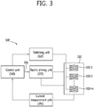
- FIG. 3 is a block diagram illustrating a wireless power transmitting apparatus according to another embodiment of the present invention.
- the wireless power transmitting apparatus 300 comprises a primary core block 310 consisting of m primary coils 310-1, ..., 310-m, a switching unit 320, an electric driving unit 330, a control unit 340, and a current measurement unit 350.
- the switching unit 320 by employing a switching method, connects all or at least one of the m primary coils 310-1, ..., 310-m selectively to the electric driving unit 330.
- the electric driving unit 330 is connected to the m primary coils 310-1, ..., 310-m through the switching unit 320 and applies electrical driving signals to n primary coils 310-1, ..., 310-n simultaneously or to at least one primary coil selected from the n primary coils 310-1, ..., 310-n to generate an electromagnetic field.
- the control unit 340 being connected to the electric driving unit 330, generates a control signal 341 which controls an AC signal required for the n primary coils 310-1, ..., 310-n to generate an induced magnetic field or resonance.
- the current measurement unit 350 measures currents flowing through the m primary coils 310-1, ..., 310-m individually or together.
- the current measurement unit 350 may measure an alternating current.
- the current measurement unit 350 may be made of a current sensor.
- the current measurement unit 350 may be a transformer used to scale down a high current flowing through the primary coil to a low current.
- the current measurement unit 350 selects only those primary coils through which currents flow from among the m primary coils 310-1, ..., 310-m, measures the current flowing through the selected primary coils respectively, obtains a plurality of individual current measurement values I 1 , I 2 , ..., I m , and inputs the measured values to the control unit 340.
- the current measurement values I 1 , I 2 , ..., I m may be what have been converted to DC values appropriate for the control unit 340 to recognize.
- the current measurement unit 350 measures relatively high alternating currents flowing through the primary coils 310-1, ..., 310-m, maps the measured high currents into current measurement values I 1 , I 2 , ..., I m appropriate for analysis by the control unit 340 as shown in Table 1, and provides the current measurement values I 1 , I 2 , . .., I m to the control unit 340.
- the current measurement unit 350 selects only those primary coils through which currents flow from among the m primary coils 310-1, ..., 310-m, measures the currents flowing through the whole of the selected primary coils, and inputs the single, whole current measurement value I SELECTED to the control unit 340.
- the current measurement unit 350 measures a total amount of currents flowing through the m primary coils 310-1, ... 310-m and provides the single, whole current measurement value I TOTAL to the control unit 340.
- control unit 340 may use one or a combination of two or more of the parameters such as reference current I ref , reference range (I low ⁇ I high ), reference AC signal, and foreign object detection time t. And the parameters such as the reference current I ref , reference range (I low ⁇ I high ), reference AC signal, and foreign object detection time t may be stored in the control unit 340 as the initial setting values.
- the control unit 340 compares the current measurement values I 1 , I 2 , ..., I m individually with the reference current I ref . If at least one of the current measurement values I 1 , I 2 , ..., I m exceeds the reference current I ref (namely, I 1 or I 2 or ... I m > I ref ), it is determined that a foreign object has been detected. On the other hand, all of the current measurement values I 1 , I 2 , ..., I m are below the reference current I ref (namely, I 1 and I 2 and ... I m ⁇ I ref ), it is determined that no foreign object is detected.
- the control unit 340 examines whether each of the current measurement values I 1 , I 2 , ..., I m belongs to the reference range (I low ⁇ I high ). If at least one of the current measurement values I 1 , I 2 , ..., I m belongs to the reference range (namely, I low ⁇ I 1 or I 2 or ... I m ⁇ I high ), it is determined that no foreign object is detected. On the other hand, all of the current measurement values I 1 , I 2 , ..., I m do not belong to the reference range (namely, I 1 and I 2 and ... I m > I high or I 1 and I 2 and ... I m ⁇ I low ), it is determined that a foreign object has been detected.
- control unit 340 compares a current measurement value I SELECTED with the reference current I ref . If the current measurement value I SELECTED exceeds the reference current I ref (namely, I SELECTED > I ref ), it is determined that a foreign object has been detected. On the other hand, if the current measurement value I SELECTED is below the reference current I ref (namely, I SELECTED ⁇ I ref ), it is determined that no foreign object is detected.
- the control unit 340 examines whether the current measurement value I SELECTED belongs to the reference range (I low ⁇ I high ). If the current measurement value I SELECTED belongs to the reference range (namely, I low ⁇ I SELECTED ⁇ I high ), it is determined that no foreign object is detected. On the other hand, if the current measurement value I SELECTED does not belong to the reference range (namely, I SELECTED > I high or I SELECTED ⁇ I low ), it is determined that a foreign object has been detected.
- control unit 340 compares a current measurement value I TOTAL with the reference current I ref . If the current measurement value I TOTAL exceeds the reference current I ref (namely, I TOTAL > I ref ), it is determined that a foreign object has been detected. On the other hand, if the current measurement value I TOTAL is below the reference current I ref (namely, I TOTAL ⁇ I ref ), it is determined that no foreign object is detected.
- control unit 340 examines whether the current measurement value I TOTAL belongs to the reference range (I low ⁇ I high ). If the current measurement value I TOTAL belongs to the reference range (namely, I low ⁇ I TOTAL ⁇ I high ), it is determined that no foreign object is detected. On the other hand, if the current measurement value I TOTAL does not belong to the reference range (namely, I TOTAL > I high or I TOTAL ⁇ I low ), it is determined that a foreign object has been detected.
- the control unit 340 may attempt to detect foreign objects at time t predetermined by the system or standard.
- the time t at which the control unit 340 attempts to detect foreign objects may be a time point after each power control is done.
- the wireless power transmitting apparatus 300 increases or decrease AC signals after receiving a power increase request message or power decrease request message from the wireless power receiving apparatus; and attempts to detect a foreign object by using a measurement value of the current flowing through the primary core block 310.
- the time t at which the control unit 340 attempts to detect foreign objects may be defined according to a predetermined detection period.
- the detection period should be shorter at least than the time period required for a foreign object to develop heat above a predetermined temperature. This is so because a serious safety problem such as outbreak of fire and bodily burns may be caused as excessive heat is developed by the foreign object. Therefore, it is preferable to set the detection period to a value safety of which has been verified by experiments, and by doing so, various factors such as heat developed by a foreign object, which may be caused during wireless charging and lead to a dangerous situation, may be prevented.
- control unit 340 blocks or stops wireless power transfer by controlling the electric driving unit 330 so that an AC signal is not applied to the primary coil 310.
- the wireless power transmitting apparatus 110 of FIG. 1 may correspond to the wireless power transmitting apparatus 200 of FIG. 2 or wireless power transmitting apparatus 300 of FIG. 3 .
- signaling overhead may be reduced since it is not necessary for the wireless power receiving apparatus to transmit particular information to the wireless power transmitting apparatus 200 according to a predefined information transmission specification to detect a foreign object.
- the wireless power transmitting apparatus 200 may detect a foreign object autonomously, however, the present invention provides an advantageous effect of obviating a delay consequent to detection of the foreign object, namely the time period for the wireless power receiving apparatus to generate particular information, time period for the particular information to be transmitted to the wireless power transmitting apparatus 200, and time period for the wireless power transmitting apparatus 200 to decode and analyze the particular information.
- the wireless power transmitting system according to the present invention may still ensure compatibility with the low version model.
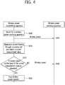
- FIG. 4 is a flow diagram illustrating operation of a wireless power transmitting system according to one embodiment of the present invention.
- the wireless power transmitting apparatus searches for a wireless power receiving apparatus S400. At this time, the wireless power transmitting apparatus is in a standby for charging until a wireless power receiving apparatus is found.
- the wireless power transmitting apparatus enters a charging mode and transmits wireless power to the wireless power receiving apparatus S405.
- the wireless power transmitting apparatus applies electric power to the primary coil and generates an induced magnetic field or resonance.
- the wireless power transmitting apparatus measures a current flowing through the primary coil and obtains a current measurement value from the current flowing through the primary coil S410.
- the current measured by the wireless power transmitting apparatus may be an alternating current.
- the current measurement value may have been converted to a DC value appropriate for the control unit within the wireless power transmitting apparatus to recognize.
- the wireless power transmitting apparatus measures a relatively high alternating current flowing through the primary coil and maps the measured high current into a current measurement value appropriate for analysis by the control unit as shown in Table 1.
- the wireless power transmitting apparatus uses one or a combination of two or more of the parameters such as reference current I ref , reference range (I low ⁇ I high ), reference AC signal, and foreign object detection time t to check if a foreign object is detected S415. And the parameters such as the reference current I ref , reference range (I low ⁇ I high ), reference AC signal, and foreign object detection time t may be stored in the wireless power transmitting apparatus as the initial setting values.
- the wireless power transmitting apparatus transmits power to the wireless power receiving apparatus continuously if a foreign object is not detected S420. And the wireless power transmitting apparatus obtains a current measurement value of the primary coil again at the time t predetermined by system or standard S410 and attempts to detect a foreign object on the basis of the obtained measurement value S415.
- the wireless power transmitting apparatus blocks wireless power which is being transmitted to the wireless power receiving apparatus S425.
- FIG. 5 is a flow diagram illustrating operation of a wireless power transmitting apparatus according to one embodiment of the present invention.
- the flow diagram of FIG. 5 illustrates the operation of the wireless power transmitting apparatus of FIG. 2 .
- the wireless power transmitting apparatus is in a standby for charging until a wireless power receiving apparatus is found S500.
- the wireless power transmitting apparatus continuously discovers a target object to which electric power is transmitted S505. If no object is found, the wireless power transmitting apparatus returns to the standby for charging S500.
- the wireless power transmission apparatus determines whether the discovered object is a wireless power receiving apparatus capable of receiving wireless power in a normal manner S510. In case the discovered object is not a wireless power receiving apparatus, the wireless power transmitting apparatus blocks or stops electric power transfer S515.
- the wireless power transmitting apparatus enters a charging mode S520.
- the wireless power transmitting apparatus In the charging mode, the wireless power transmitting apparatus generates an induced magnetic field or resonance by applying electric power to the primary coil.
- the wireless power transmitting apparatus measures a current flowing through the primary coil S525.
- the current measured by the wireless power transmitting apparatus may be an alternating current.
- the wireless power transmitting apparatus obtains a current measurement value I measured from the current flowing through the primary coil S530.
- the current measurement value I measured may be what have been converted to a DC value appropriate for the control unit within the wireless power transmitting apparatus to recognize.
- the wireless power transmitting apparatus measures a relatively high alternating current flowing through the primary coil and maps the measured high current into a current measurement value I measured appropriate for analysis by the control unit as shown in Table 1.
- the wireless power transmitting apparatus uses one or a combination of two or more of the parameters such as reference current I ref , reference range (I low ⁇ I high ), reference AC signal, and foreign object detection time t to check if a foreign object is detected S535. And the parameters such as the reference current I ref , reference range (I low ⁇ I high ), reference AC signal, and foreign object detection time t may be stored in the wireless power transmitting apparatus as the initial setting values.
- the wireless power transmitting apparatus compares the current measurement value I measured with the reference current I ref . If the current measurement value I measured exceeds the reference current I ref (in other words, I measured > I ref ), it is determined that a foreign object has been detected. On the other hand, if the current measurement value I measured is below the reference current I ref (namely, I measured ⁇ I ref ), it is determined that no foreign object is detected.
- the wireless power transmitting apparatus examines whether the current measurement value I measured belongs to the reference range (I low ⁇ I high ). And if the current measurement value I measured belongs to the reference range (namely, I low ⁇ I measured ⁇ I high ), the wireless power transmitting apparatus determines that no foreign object is detected. On the other hand, if the current measurement value I measured is out of the reference range (in other words, I measured > I high or I measured ⁇ I low ), the wireless power transmitting apparatus determines that a foreign object has been detected.
- the wireless power transmitting apparatus blocks or stops wireless power which is being transmitted to the wireless power receiving apparatus S515.
- the wireless power transmitting apparatus transmits power to the wireless power receiving apparatus continuously S540. And the wireless power transmitting apparatus measures a current of the primary coil again at the time t predetermined by system or standard S525, obtains a current measurement value S530, and attempts to detect a foreign object on the basis of the obtained measurement value S535.
- the time t at which the wireless power transmitting apparatus attempts to detect foreign objects may be a time point after each power control time.
- the wireless power transmitting apparatus increases or decrease AC signals after receiving a power increase request message or power decrease request message from the wireless power receiving apparatus; and attempts to detect a foreign object by using a measurement value of the current flowing through the primary core block.
- the time t at which the wireless power transmitting apparatus attempts detection of a foreign object may correspond to a predetermined detection period.
- the detection period should be shorter than the time period needed for a foreign object to develop heat above a predetermined temperature. It is so because a serious safety problem such as outbreak of fire and bodily burns may be caused as excessive heat is developed. Therefore, it is preferable to set the detection period to a value safety of which has been verified by experiments, and by doing so, various factors such as heat developed by a foreign object, which may be caused during wireless charging and lead to a dangerous situation, may be prevented.
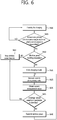
- FIG. 6 is a flow diagram illustrating operation of a wireless power transmitting apparatus according to another embodiment of the present invention.
- the flow diagram of FIG. 5 illustrates the operation of the wireless power transmitting apparatus of FIG. 3 .
- the wireless power transmitting apparatus is in a standby for charging until a wireless power receiving apparatus is found S600.
- the wireless power transmitting apparatus continuously discovers a target object to which electric power is transmitted by using m primary coils S605. If no object is found from at least one of the m primary coils, the wireless power transmitting apparatus returns to the standby for charging S600.
- the wireless power transmission apparatus determines whether the discovered object is a wireless power receiving apparatus capable of receiving wireless power in a normal manner S610. In case the discovered object is not a wireless power receiving apparatus, the wireless power transmitting apparatus blocks or stops electric power transfer S615.
- the wireless power transmitting apparatus enters a charging mode S620.
- the wireless power transmitting apparatus In the charging mode, the wireless power transmitting apparatus generates an induced magnetic field or resonance by applying electric power to the primary coil.
- the wireless power transmitting apparatus measures currents flowing through the m primary coil S625 individually or together.
- the current measured by the wireless power transmitting apparatus may be an alternating current.
- the wireless power transmitting apparatus obtains one or more current measurement values S630.
- the wireless power transmitting apparatus selects only those primary coils through which currents flow from among the m primary coils, measures the current flowing through the selected primary coils respectively, and obtains a plurality of individual current measurement values I 1 , I 2 , ..., I m .
- the current measurement values I 1 , I 2 , ..., I m may have been converted to DC values appropriate for the wireless power transmitting apparatus to recognize.
- the wireless power transmitting apparatus measures relatively high alternating currents flowing through the primary coils and maps the measured high currents into current measurement values I 1 , I 2 , ..., I m as shown in Table 1.
- the wireless power transmitting apparatus selects only those primary coils through which currents flow from among the m primary coils and obtains a current measurement value by measuring a current flowing through the whole of the selected primary coils.
- the wireless power transmitting apparatus measures a total amount of currents flowing through the m primary coils and obtains the single, whole current measurement value I TOTAL as a current measurement value.
- the wireless power transmitting apparatus may use one or a combination of two or more of the parameters such as reference current I ref , reference range (I low ⁇ I high ), reference AC signal, and foreign object detection time t to check if a foreign object is detected S635. And the parameters such as the reference current I ref , reference range (I low ⁇ I high ), reference AC signal, and foreign object detection time t may be stored in the wireless power transmitting apparatus as the initial setting values.
- the wireless power transmitting apparatus compares the current measurement values I 1 , I 2 , ..., I m individually with the reference current I ref . If at least one of the current measurement values I 1 , I 2 , ..., I m exceeds the reference current I ref (namely, I 1 or I 2 or ... I m > I ref ), it is determined that a foreign object has been detected. On the other hand, all of the current measurement values I 1 , I 2 , ..., I m are below the reference current I ref (namely, I 1 and I 2 and ... I m ⁇ I ref ), it is determined that no foreign object is detected.
- the wireless power transmitting apparatus examines whether each of the current measurement values I 1 , I 2 , ..., I m belongs to the reference range (I low ⁇ I high ). If at least one of the current measurement values I 1 , I 2 , ..., I m belongs to the reference range (namely, I low ⁇ I 1 or I 2 or ... I m ⁇ I high ), it is determined that no foreign object is detected. On the other hand, all of the current measurement values I 1 , I 2 , ..., I m do not belong to the reference range (namely, I 1 and I 2 and ... I m > I high or I 1 and I 2 and ... I m ⁇ I low ), it is determined that a foreign object has been detected.
- the wireless power transmitting apparatus compares a current measurement value I SELECTED with the reference current I ref . If the current measurement value I SELECTED exceeds the reference current I ref (namely, I SELECTED > I ref ), it is determined that a foreign object has been detected. On the other hand, if the current measurement value I SELECTED is below the reference current I ref (namely, I SELECTED ⁇ I ref ), it is determined that no foreign object is detected.
- the wireless power transmitting apparatus examines whether the current measurement value I SELECTED belongs to the reference range (I low ⁇ I high ). If the current measurement value I SELECTED belongs to the reference range (namely, I low ⁇ I SELECTED ⁇ I high ), it is determined that no foreign object is detected. On the other hand, if the current measurement value I SELECTED does not belong to the reference range (namely, I SELECTED > I high or I SELECTED ⁇ I low ), it is determined that a foreign object has been detected.
- the wireless power transmitting apparatus compares a current measurement value I TOTAL with the reference current I ref . If the current measurement value I TOTAL exceeds the reference current I ref (namely, I TOTAL > I ref ), it is determined that a foreign object has been detected. On the other hand, if the current measurement value I TOTAL is below the reference current I ref (namely, I TOTAL ⁇ I ref ), it is determined that no foreign object is detected.
- the wireless power transmitting apparatus examines whether the current measurement value I TOTAL belongs to the reference range (I low ⁇ I high ). If the current measurement value I TOTAL belongs to the reference range (namely, I low ⁇ I TOTAL ⁇ I high ), it is determined that no foreign object is detected. On the other hand, if the current measurement value I TOTAL does not belong to the reference range (namely, I TOTAL > I high or I TOTAL ⁇ I low ), it is determined that a foreign object has been detected.
- the wireless power transmitting apparatus blocks or stops wireless power transfer by controlling AC signals not to be applied to the m primary core blocks S615.
- the wireless power transmitting apparatus transmits power to the wireless power receiving apparatus continuously if a foreign object is not detected S640.
- the wireless power transmitting apparatus measures currents of the m primary coils again at the time t predetermined by system or standard S625, obtains current measurement values S630, and attempts to detect a foreign object on the basis of the obtained measurement values S635.
- the wireless power transmitting apparatus may attempt to detect foreign objects at the time t predetermined by system or standard.
- the time t at which the wireless power transmitting apparatus attempts detection of a foreign object may be a time point after each power control time.
- the wireless power transmitting apparatus receives a power increase request message or power decrease request message from the wireless power receiving apparatus and increases or decreases an AC signal accordingly. Afterwards, the wireless power transmitting apparatus may attempt detection of a foreign object by using a current measurement value flowing through the primary core block.
- the time t at which the wireless power transmitting apparatus attempts detection of a foreign object may correspond to a predetermined detection period.
- the detection period should be shorter than the time period needed for a foreign object to develop heat above a predetermined temperature. It is so because a serious safety problem such as outbreak of fire and bodily burns may be caused as excessive heat is developed. Therefore, it is preferable to set the detection period to a value safety of which has been verified by experiments, and by doing so, various factors such as heat developed by a foreign object, which may be caused during wireless charging and lead to a dangerous situation, may be prevented.
- a processor such as a microprocessor, controller, microcontroller, and ASIC (Application Specific Integrated Circuit) controlled by software or program codes implemented to perform the functions. It should be noted that the design, development, and implementation of the codes would be understood clearly to those skilled in the art on the basis of the descriptions of the present invention.
- a wireless power transmitting apparatus may autonomously recognize foreign objects coming between the wireless power transmitting apparatus and a wireless power receiving apparatus without support of the wireless power receiving apparatus. In case a foreign object is detected, the apparatus stops transmission of wireless power or lets the user to remove the foreign object, thereby preventing damage of the apparatus due to the foreign object.
Description
- The present invention is related to wireless power transmission and more particularly, an apparatus and method for detecting a foreign object in a wireless power transmitting system.
-
US 2012/175,967 A1 discloses transmitting power wirelessly by electromagnetic induction in which an electrical drive signal supplied to one or more primary coils changes from a first value to a second value. - In general, an external charger is used to charge portable terminals such as a mobile phone, notebook computer, and PDA by supplying electric energy (or electric power) thereto. Conventional portable terminals include battery cells storing supplied electric energy and a circuit intended for charging and discharging (providing electric energy to the portable terminals) the battery cells
- The electrical interface between the charger and battery cells, through which battery cells are charged with electric energy, includes contacts; the contact-type electrical interface receives commercial electricity, transforms the electricity into voltage and currents relevant to the battery cells, and provides electric energy to the battery cells through the contacts of the corresponding battery cells.
- Contacts of this kind require physical cables or use of electrical wires. Therefore, when a large number of equipment receiving electric energy through the contact-type electric interface is used, a large amount of cables tend to occupy considerable workspace and may ruin the appearance because it is not easy to arrange the cables properly. Moreover, the contact-type electrical interface may cause problems such as instant discharge due to a potential difference between contacts, abrasion and outbreak of fire due to foreign objects, spontaneous discharge, decrease of battery lifetime, and degradation of battery performance.
- Recently, to solve the aforementioned problems, charging systems employing wireless power transmission (hereinafter, it is called wireless power transmitting systems) and control methods for the systems are under development. A wireless power transmitting method is also called a contactless power transmitting method or no point-of-contact power transmitting method. A wireless power transmitting system comprises a wireless power transmitting apparatus providing electric energy through wireless power transmission and a wireless power receiving apparatus receiving electric energy provided wirelessly from the wireless power transmitting apparatus and charging battery cells by using the received electric energy.
- Once connections are well secured between a charger and a mobile terminal, the contact-type electrical interface suffers little from obstacles disturbing battery charge, such as foreign objects. Meanwhile, because of the inherent characteristics of a wireless power transmitting system utilizing no-point-of-contact charge, there is a high chance that foreign objects are inserted between the wireless power receiving apparatus and wireless power transmitting apparatus at the time of charging. In case a foreign object such as a metallic part is located between the wireless power receiving apparatus and wireless power transmitting apparatus, smooth power transmission is impaired due to the foreign object, and at the same time, problems such as damage and explosion of the corresponding product due to overload and heating of the foreign object may be caused. Therefore, there need to be an apparatus and method for detecting foreign objects in a wireless power transmitting system.
- The present invention is defined in the accompanying claims.
- An object of the present invention is to provide an apparatus and method for detecting foreign objects in a wireless power transmitting system.
- Another object of the present invention is to provide an apparatus and method for detecting foreign objects based on a current induced in a primary coil of a wireless power transmitting system.
- A yet another object of the present invention is to provide an apparatus and method for performing an operation in response to detection of foreign objects in a wireless power transmitting system.
- A still another object of the present invention is to provide an apparatus and method for wireless power transmission equipped with a function of detecting foreign objects in a wireless power transmission system.
- According to one aspect of the present invention, a wireless power transmitting apparatus detecting foreign objects is provided. The apparatus comprises a primary core block being coupled with a secondary core block installed in a wireless power receiving apparatus and transmitting wireless power to the wireless power receiving apparatus through magnetic induction or magnetic resonance; an electric driving unit applying an AC (Alternating Current) signal required for the primary core block to transmit the wireless power; a control unit being connected to the electric driving unit and generating a control signal for controlling the AC signal; and a current measurement unit measuring a current flowing into the primary core block and obtaining a current measurement value converted to a numeric value relevant for the control unit to analyze the current.
- The control unit may detect foreign objects coming between the wireless power transmitting apparatus and wireless power receiving apparatus by using a result of comparing the current measurement value with a reference value.
- According to another aspect of the present invention, a method for detecting foreign objects by a wireless power transmitting apparatus equipped with a primary core block is provided. The method comprises applying an AC signal required for transmitting wireless power to the primary core block; transmitting the wireless power to a wireless power receiving apparatus by coupling a secondary core block installed in the wireless power receiving apparatus with the primary core block through magnetic induction or magnetic resonance; obtaining a current measurement value by measuring a current flowing into the primary core block; and detecting foreign objects located between the wireless power transmitting apparatus and the wireless power receiving apparatus based on a result of comparing the current measurement value with a reference value.
- The accompanying drawings, which are included to provide a further understanding of the present invention and constitute a part of specifications of the present invention, illustrate embodiments of the present invention and together with the corresponding descriptions serve to explain the principles of the present invention.
-
FIG. 1 is a block diagram illustrating constituting elements of a wireless power transmitting system according to one embodiment of the present invention; -
FIG. 2 is a block diagram illustrating a wireless power transmitting apparatus according to one embodiment of the present invention; -
FIG. 3 is a block diagram illustrating a wireless power transmitting apparatus according to another embodiment of the present invention; -
FIG. 4 is a flow diagram illustrating operation of a wireless power transmitting system according to one embodiment of the present invention; -
FIG. 5 is a flow diagram illustrating operation of a wireless power transmitting apparatus according to one embodiment of the present invention; and -
FIG. 6 is a flow diagram illustrating operation of a wireless power transmitting apparatus according to another embodiment of the present invention. - The term of "wireless power" is used to denote the energy of arbitrary shape related to electric fields, magnetic fields, and electromagnetic fields transmitted from a transmitter to a receiver without employing physical electromagnetic conductors. The wireless power may be called a power signal and may indicate an oscillating magnetic flux enclosed by a primary and secondary coil. For example, this document describes power transformation of a system intended to charge devices such as a mobile phone, cordless phone, iPod, MP3 player, and headset wirelessly. In general, basic principles of wireless transfer of energy rely on magnetic inductive coupling, magnetic resonance coupling (namely, resonance induction) utilizing frequencies below 30 MHz, or both. For relatively high radiation levels, various frequencies below 135 kHz (LF) or above 13.56 MHz (HF), which include license-free frequencies, may be utilized.
-
FIG. 1 is a block diagram illustrating constituting elements of a wireless power transmitting system according to one embodiment of the present invention. - With reference to
FIG. 1 , a wirelesspower transmitting system 100 comprises a wirelesspower transmitting apparatus 110 and one wireless power receiving apparatus 150-1 or n wireless power receiving apparatuses 150-1, ..., 150-n. - The wireless
power transmitting apparatus 110 includes a primary core block. The primary core block may comprise a core and one or moreprimary coils 111. The wirelesspower transmitting apparatus 110 may have an arbitrary shape, but one of the preferred shapes is a flat platform with a power transmission surface; each wireless power receiving apparatus 150-1, ..., 150-n may be disposed on or around the platform. - The wireless power receiving apparatus 150-1, ..., 150-n may be separated from the wireless
power transmitting apparatus 110; each of the wireless power receiving apparatus 150-1, ..., 150-n is equipped with a secondary core block coupled with an electromagnetic field generated by the primary core block of the wirelesspower transmitting apparatus 110 in the vicinity thereof. The secondary core block may comprise one or moresecondary coils 151. - The wireless
power transmitting apparatus 110 transmits power to the wireless power receiving apparatus 150-1, ..., 150-n without a direct electric contact. In this case, the primary core block and secondary core block are referred to as being coupled with each other through magnetic induction or resonance induction. The primary and secondary coil may assume an arbitrary shape relevant to each other; for example, the coils may be in the form of copper wires wound along the periphery of a block made from a high permeability material such as ferrite or amorphous metal. - The wireless power receiving apparatus 150-1, ..., 150-n is connected to an external load (not shown. In this document, it is also called an actual load of the wireless power receiving apparatus) and provides power received wirelessly from the wireless
power transmitting apparatus 110 to the external load. For example, the wireless power receiving apparatus 150-1, ..., 150-n may each convey the received power to an object which consumes or stores electric power, such as a portable electric or electronic device, rechargeable battery cell, or battery. -
FIG. 2 is a block diagram illustrating a wireless power transmitting apparatus according to one embodiment of the present invention. - With reference to
FIG. 2 , the wirelesspower transmitting apparatus 200 comprises aprimary coil 210,electric driving unit 220,control unit 230, andcurrent measurement unit 240. - The
electric driving unit 220 is connected to theprimary coil 210 and applies electric driving signals to theprimary coil 210 to generate an electromagnetic field. - The
control unit 230 is connected to theelectric driving unit 220 and generates acontrol signal 231 for controlling an AC signal needed for theprimary coil 210 to generate an induced magnetic field or magnetic resonance. - The
current measurement unit 240 measures a current flowing into theprimary coil 210. In particular, the current measured by thecurrent measurement unit 240 may be an alternating current. Thecurrent measurement unit 240 may be a current sensor. Also, thecurrent measurement unit 240 may be a transformer used to scale down a high current flowing through the primary coil to a low current. - The
current measurement unit 240 obtains a current measurement value Imeasured from the current flowing through theprimary coil 210 and provides the obtained value to thecontrol unit 230. The current measurement value Imeasured may have been converted to a DC value appropriate for thecontrol unit 230 to recognize. In other words, thecurrent measurement unit 240 measures a relatively high alternating current flowing through theprimary coil 210, maps the measured high current into a current measurement value Imeasured appropriate for analysis by thecontrol unit 230, and provides the current measurement value Imeasured to thecontrol unit 230. - Hereinafter, described in detail will be which operation each constituting element of the wireless
power transmitting apparatus 200 performs to detect a foreign object. - If the
control unit 230 sends acontrol signal 231 corresponding to a reference AC signal to theelectric driving unit 220, theelectric driving unit 220 applies the reference AC signal to theprimary coil 210. Here, the reference AC signal is an AC signal designed to make transmission efficiency of wireless power belong to a nominal range (or designed to satisfy the required electric power level of a receiving apparatus) in an environment free of foreign objects, namely in an environment not suffering from any obstacles against transmission of wireless power and may be obtained experimentally. If the reference AC signal is applied to theprimary coil 210, a reference current Iref flows through theprimary coil 210 and, wireless power Wref is transmitted. - If a foreign object comes between the wireless
power transmitting apparatus 200 and the wireless power receiving apparatus, however, the foreign object consumes an amount of power WF0, and the wireless power receiving apparatus only receives the remaining power Wref-WF0. If the wireless power receiving apparatus fails to receive as much power as WF0, the wireless power receiving apparatus transmits power increase request message to the wirelesspower transmitting apparatus 200 to request more power. The power increase request message may be called a control error packet. On the other hand, if the wireless power receiving apparatus receives power more than requested, the wireless power receiving apparatus may transmit a power decrease request message to the wirelesspower transmitting apparatus 200. - The wireless power receiving apparatus may transmit the power increase request message or power decrease request message to the wireless
power transmitting apparatus 200 continuously until requested power is obtained. For example, the wirelesspower transmitting apparatus 200 which has received the power increase request message increases intensity of the current flowing through theprimary coil 210 in response to the message, so that higher power may be transmitted. More specifically, to make a larger current flow through theprimary coil 210, thecontrol unit 230 may adjust acontrol signal 231 so that an AC signal larger than the reference AC signal may be applied to theprimary coil 210. Series of such processes are collectively called power control. - As a result of power control, the current measurement value Imeasured in the
primary coil 210 may become larger than a predetermined range. The fact that the current Imeasured larger than the reference current Iref is flowing through theprimary coil 210 for transmission of required electric power indicates drop of transmission efficiency of wireless power, and at the same time, implies that a predetermined amount of electric power is continuously consumed due to a foreign object in addition to the wireless power receiving apparatus. Therefore, in case a relatively large current flows in theprimary coil 210, thecontrol unit 230 decides that a foreign object exists in the transmission path of electric power. In other words, on the basis of the current measurement value Imeasured, thecontrol unit 230 may detect a foreign object such as metal which causes interference on transmission of wireless power. - To detect a foreign object, the
control unit 230 may use one or a combination of two or more of the parameters such as reference current Iref, reference range (Ilow ∼ Ihigh), reference AC signal, and foreign object detection time t. And the parameters such as the reference current Iref, reference range (Ilow ∼ Ihigh), reference AC signal, and foreign object detection time t may be stored in thecontrol unit 230 as the initial setting values. The reference current Iref and reference range (Ilow ∼ Ihigh) may be called reference values. - As one example, the
control unit 230 compares the current measurement value Imeasured with the reference current Iref. If the current measurement value Imeasured exceeds the reference current Iref (in other words, Imeasured > Iref), it is determined that a foreign object has been detected. On the other hand, if the current measurement value Imeasured is below the reference current Iref (namely, Imeasured ≤Iref), it is determined that no foreign object is detected. At this time, the reference current Iref may be defined as follows according to the rated power W of the wireless power receiving apparatus.[Table 1] Rx power(unit : W) Tx AC current(unit : A) Max AC current(unit : A) 2.5 0.998 1.05 3 1.328 1.5 4 1.664 1.85 5 1.925 2.05 - With reference to Table 1, when the rated power W of the wireless power receiving apparatus Rx is 2.5W, 3W, 4W, and 5W, the AC current flowing through the primary core block of the wireless power transmitting apparatus Tx is found experimentally to be 0.998A, 1.328A, 1.664A, and 1.925A, respectively. And the reference current allowed in the primary core block, namely the size of Iref is 1.05A, 1.5A, 1.85A, and 2.05A.
- As another example, the
control unit 230 examines whether the current measurement value Imeasured belongs to the reference range (Ilow ∼ Ihigh). And if the current measurement value Imeasured belongs to the reference range (namely, Ilow ≤ Imeasured ≤ Ihigh), thecontrol unit 230 determines that no foreign object is detected. On the other hand, if the current measurement value Imeasured is out of the reference range (in other words, Imeasured > Ihigh or Imeasured < Ilow), thecontrol unit 230 determines that a foreign object has been detected. - The
control unit 230 may attempt to detect a foreign object at the time t predetermined by system or standard. - As one example, the time t at which the
control unit 230 attempts detection of a foreign object may be a time point after each power control is done. For example, the wirelesspower transmitting apparatus 200 receives a power increase request message or power decrease request message from the wireless power receiving apparatus and increases or decreases the AC signal accordingly. Afterwards, thecontrol unit 230 may attempt detection of a foreign object by using a current measurement value flowing through theprimary coil 210. - As another example, the time t at which the
control unit 230 attempts detection of a foreign object may correspond to a predetermined detection period. For example, the detection period should be shorter than the time period needed for a foreign object to develop heat above a predetermined temperature. It is so because a serious safety problem such as outbreak of fire and bodily burns may be caused as excessive heat is developed. Therefore, it is preferable to set the detection period to a value safety of which has been verified by experiments, and by doing so, various factors such as heat developed by a foreign object, which may be caused during wireless charging and lead to a dangerous situation, may be prevented. - When a foreign object is detected, the control unit 20 blocks or stops wireless power transfer by controlling the
electric driving unit 220 so that an AC signal is not applied to theprimary coil 210. -
FIG. 3 is a block diagram illustrating a wireless power transmitting apparatus according to another embodiment of the present invention. - With reference to
FIG. 3 , the wirelesspower transmitting apparatus 300 comprises aprimary core block 310 consisting of m primary coils 310-1, ..., 310-m, aswitching unit 320, anelectric driving unit 330, acontrol unit 340, and acurrent measurement unit 350. - The
switching unit 320, by employing a switching method, connects all or at least one of the m primary coils 310-1, ..., 310-m selectively to theelectric driving unit 330. - The
electric driving unit 330 is connected to the m primary coils 310-1, ..., 310-m through theswitching unit 320 and applies electrical driving signals to n primary coils 310-1, ..., 310-n simultaneously or to at least one primary coil selected from the n primary coils 310-1, ..., 310-n to generate an electromagnetic field. - The
control unit 340, being connected to theelectric driving unit 330, generates acontrol signal 341 which controls an AC signal required for the n primary coils 310-1, ..., 310-n to generate an induced magnetic field or resonance. - The
current measurement unit 350 measures currents flowing through the m primary coils 310-1, ..., 310-m individually or together. In particular, thecurrent measurement unit 350 may measure an alternating current. Thecurrent measurement unit 350 may be made of a current sensor. Also, thecurrent measurement unit 350 may be a transformer used to scale down a high current flowing through the primary coil to a low current. - As one example, the
current measurement unit 350 selects only those primary coils through which currents flow from among the m primary coils 310-1, ..., 310-m, measures the current flowing through the selected primary coils respectively, obtains a plurality of individual current measurement values I1, I2, ..., Im, and inputs the measured values to thecontrol unit 340. The current measurement values I1, I2, ..., Im may be what have been converted to DC values appropriate for thecontrol unit 340 to recognize. In other words, thecurrent measurement unit 350 measures relatively high alternating currents flowing through the primary coils 310-1, ..., 310-m, maps the measured high currents into current measurement values I1, I2, ..., Im appropriate for analysis by thecontrol unit 340 as shown in Table 1, and provides the current measurement values I1, I2, . .., Im to thecontrol unit 340. - As another example, the
current measurement unit 350 selects only those primary coils through which currents flow from among the m primary coils 310-1, ..., 310-m, measures the currents flowing through the whole of the selected primary coils, and inputs the single, whole current measurement value ISELECTED to thecontrol unit 340. - As a yet another example, the
current measurement unit 350 measures a total amount of currents flowing through the m primary coils 310-1, ... 310-m and provides the single, whole current measurement value ITOTAL to thecontrol unit 340. - To detect a foreign object, the
control unit 340 may use one or a combination of two or more of the parameters such as reference current Iref, reference range (Ilow ∼ Ihigh), reference AC signal, and foreign object detection time t. And the parameters such as the reference current Iref, reference range (Ilow ∼ Ihigh), reference AC signal, and foreign object detection time t may be stored in thecontrol unit 340 as the initial setting values. - As one example, the
control unit 340 compares the current measurement values I1, I2, ..., Im individually with the reference current Iref. If at least one of the current measurement values I1, I2, ..., Im exceeds the reference current Iref (namely, I1 or I2 or ... Im > Iref), it is determined that a foreign object has been detected. On the other hand, all of the current measurement values I1, I2, ..., Im are below the reference current Iref (namely, I1 and I2 and ... Im ≤Iref), it is determined that no foreign object is detected. - As another example, the
control unit 340 examines whether each of the current measurement values I1, I2, ..., Im belongs to the reference range (Ilow ∼ Ihigh). If at least one of the current measurement values I1, I2, ..., Im belongs to the reference range (namely, Ilow ≤ I1 or I2 or ... Im ≤ Ihigh), it is determined that no foreign object is detected. On the other hand, all of the current measurement values I1, I2, ..., Im do not belong to the reference range (namely, I1 and I2 and ... Im > Ihigh or I1 and I2 and ... Im < Ilow), it is determined that a foreign object has been detected. - As a yet another example, the
control unit 340 compares a current measurement value ISELECTED with the reference current Iref. If the current measurement value ISELECTED exceeds the reference current Iref (namely, ISELECTED > Iref), it is determined that a foreign object has been detected. On the other hand, if the current measurement value ISELECTED is below the reference current Iref (namely, ISELECTED ≤Iref), it is determined that no foreign object is detected. - As a still another example, the
control unit 340 examines whether the current measurement value ISELECTED belongs to the reference range (Ilow ∼ Ihigh). If the current measurement value ISELECTED belongs to the reference range (namely, Ilow ≤ ISELECTED ≤ Ihigh), it is determined that no foreign object is detected. On the other hand, if the current measurement value ISELECTED does not belong to the reference range (namely, ISELECTED > Ihigh or ISELECTED < Ilow), it is determined that a foreign object has been detected. - As a further example, the
control unit 340 compares a current measurement value ITOTAL with the reference current Iref. If the current measurement value ITOTAL exceeds the reference current Iref (namely, ITOTAL > Iref), it is determined that a foreign object has been detected. On the other hand, if the current measurement value ITOTAL is below the reference current Iref (namely, ITOTAL ≤Iref), it is determined that no foreign object is detected. - As an additional example, the
control unit 340 examines whether the current measurement value ITOTAL belongs to the reference range (Ilow ∼ Ihigh). If the current measurement value ITOTAL belongs to the reference range (namely, Ilow ≤ ITOTAL ≤ Ihigh), it is determined that no foreign object is detected. On the other hand, if the current measurement value ITOTAL does not belong to the reference range (namely, ITOTAL > Ihigh or ITOTAL < Ilow), it is determined that a foreign object has been detected. - The
control unit 340 may attempt to detect foreign objects at time t predetermined by the system or standard. - As one example, the time t at which the
control unit 340 attempts to detect foreign objects may be a time point after each power control is done. For example, the wirelesspower transmitting apparatus 300 increases or decrease AC signals after receiving a power increase request message or power decrease request message from the wireless power receiving apparatus; and attempts to detect a foreign object by using a measurement value of the current flowing through theprimary core block 310. - As another example, the time t at which the
control unit 340 attempts to detect foreign objects may be defined according to a predetermined detection period. For example, the detection period should be shorter at least than the time period required for a foreign object to develop heat above a predetermined temperature. This is so because a serious safety problem such as outbreak of fire and bodily burns may be caused as excessive heat is developed by the foreign object. Therefore, it is preferable to set the detection period to a value safety of which has been verified by experiments, and by doing so, various factors such as heat developed by a foreign object, which may be caused during wireless charging and lead to a dangerous situation, may be prevented. - When a foreign object is detected, the
control unit 340 blocks or stops wireless power transfer by controlling theelectric driving unit 330 so that an AC signal is not applied to theprimary coil 310. - The wireless
power transmitting apparatus 110 ofFIG. 1 may correspond to the wirelesspower transmitting apparatus 200 ofFIG. 2 or wirelesspower transmitting apparatus 300 ofFIG. 3 . - According to the present invention, signaling overhead may be reduced since it is not necessary for the wireless power receiving apparatus to transmit particular information to the wireless
power transmitting apparatus 200 according to a predefined information transmission specification to detect a foreign object. - Detection of a foreign object with the least delay before the foreign object develops heat is a very important technical issue. This is so because if a foreign object readily develops heat by nature, a long delay before detecting the foreign object may cause a serious problem. Since the wireless
power transmitting apparatus 200 may detect a foreign object autonomously, however, the present invention provides an advantageous effect of obviating a delay consequent to detection of the foreign object, namely the time period for the wireless power receiving apparatus to generate particular information, time period for the particular information to be transmitted to the wirelesspower transmitting apparatus 200, and time period for the wirelesspower transmitting apparatus 200 to decode and analyze the particular information. - Furthermore, even if the wireless power receiving apparatus is of a low version model unable to transmit the particular information, the wireless power transmitting system according to the present invention may still ensure compatibility with the low version model.
-
FIG. 4 is a flow diagram illustrating operation of a wireless power transmitting system according to one embodiment of the present invention. - With reference to
FIG. 4 , the wireless power transmitting apparatus searches for a wireless power receiving apparatus S400. At this time, the wireless power transmitting apparatus is in a standby for charging until a wireless power receiving apparatus is found. - If a detected object is a wireless power receiving apparatus, the wireless power transmitting apparatus enters a charging mode and transmits wireless power to the wireless power receiving apparatus S405. In the charging mode, the wireless power transmitting apparatus applies electric power to the primary coil and generates an induced magnetic field or resonance.
- The wireless power transmitting apparatus measures a current flowing through the primary coil and obtains a current measurement value from the current flowing through the primary coil S410. The current measured by the wireless power transmitting apparatus may be an alternating current. The current measurement value may have been converted to a DC value appropriate for the control unit within the wireless power transmitting apparatus to recognize. In other words, the wireless power transmitting apparatus measures a relatively high alternating current flowing through the primary coil and maps the measured high current into a current measurement value appropriate for analysis by the control unit as shown in Table 1.
- The wireless power transmitting apparatus uses one or a combination of two or more of the parameters such as reference current Iref, reference range (Ilow ∼ Ihigh), reference AC signal, and foreign object detection time t to check if a foreign object is detected S415. And the parameters such as the reference current Iref, reference range (Ilow ∼ Ihigh), reference AC signal, and foreign object detection time t may be stored in the wireless power transmitting apparatus as the initial setting values.
- The wireless power transmitting apparatus transmits power to the wireless power receiving apparatus continuously if a foreign object is not detected S420. And the wireless power transmitting apparatus obtains a current measurement value of the primary coil again at the time t predetermined by system or standard S410 and attempts to detect a foreign object on the basis of the obtained measurement value S415.
- On the other hand, if a foreign object is detected, the wireless power transmitting apparatus blocks wireless power which is being transmitted to the wireless power receiving apparatus S425.
-
FIG. 5 is a flow diagram illustrating operation of a wireless power transmitting apparatus according to one embodiment of the present invention. The flow diagram ofFIG. 5 illustrates the operation of the wireless power transmitting apparatus ofFIG. 2 . - With reference to
FIG. 5 , the wireless power transmitting apparatus is in a standby for charging until a wireless power receiving apparatus is found S500. - At this time, the wireless power transmitting apparatus continuously discovers a target object to which electric power is transmitted S505. If no object is found, the wireless power transmitting apparatus returns to the standby for charging S500.
- If an object is discovered at step S505, the wireless power transmission apparatus determines whether the discovered object is a wireless power receiving apparatus capable of receiving wireless power in a normal manner S510. In case the discovered object is not a wireless power receiving apparatus, the wireless power transmitting apparatus blocks or stops electric power transfer S515.
- If the discovered object is a wireless power receiving apparatus, the wireless power transmitting apparatus enters a charging mode S520. In the charging mode, the wireless power transmitting apparatus generates an induced magnetic field or resonance by applying electric power to the primary coil.
- The wireless power transmitting apparatus measures a current flowing through the primary coil S525. In particular, the current measured by the wireless power transmitting apparatus may be an alternating current.
- The wireless power transmitting apparatus obtains a current measurement value Imeasured from the current flowing through the primary coil S530. The current measurement value Imeasured may be what have been converted to a DC value appropriate for the control unit within the wireless power transmitting apparatus to recognize. In other words, the wireless power transmitting apparatus measures a relatively high alternating current flowing through the primary coil and maps the measured high current into a current measurement value Imeasured appropriate for analysis by the control unit as shown in Table 1.
- The wireless power transmitting apparatus uses one or a combination of two or more of the parameters such as reference current Iref, reference range (Ilow ∼ Ihigh), reference AC signal, and foreign object detection time t to check if a foreign object is detected S535. And the parameters such as the reference current Iref, reference range (Ilow ∼ Ihigh), reference AC signal, and foreign object detection time t may be stored in the wireless power transmitting apparatus as the initial setting values.
- As one example, the wireless power transmitting apparatus compares the current measurement value Imeasured with the reference current Iref. If the current measurement value Imeasured exceeds the reference current Iref (in other words, Imeasured > Iref), it is determined that a foreign object has been detected. On the other hand, if the current measurement value Imeasured is below the reference current Iref (namely, Imeasured ≤Iref), it is determined that no foreign object is detected.
- As another example, the wireless power transmitting apparatus examines whether the current measurement value Imeasured belongs to the reference range (Ilow ∼ Ihigh). And if the current measurement value Imeasured belongs to the reference range (namely, Ilow ≤ Imeasured ≤ Ihigh), the wireless power transmitting apparatus determines that no foreign object is detected. On the other hand, if the current measurement value Imeasured is out of the reference range (in other words, Imeasured > Ihigh or Imeasured < Ilow), the wireless power transmitting apparatus determines that a foreign object has been detected.
- If a foreign object is detected at step S535, the wireless power transmitting apparatus blocks or stops wireless power which is being transmitted to the wireless power receiving apparatus S515.
- On the other hand, if a foreign object is not detected at step S535, the wireless power transmitting apparatus transmits power to the wireless power receiving apparatus continuously S540. And the wireless power transmitting apparatus measures a current of the primary coil again at the time t predetermined by system or standard S525, obtains a current measurement value S530, and attempts to detect a foreign object on the basis of the obtained measurement value S535.
- As one example, the time t at which the wireless power transmitting apparatus attempts to detect foreign objects may be a time point after each power control time. For example, the wireless power transmitting apparatus increases or decrease AC signals after receiving a power increase request message or power decrease request message from the wireless power receiving apparatus; and attempts to detect a foreign object by using a measurement value of the current flowing through the primary core block.
- As another example, the time t at which the wireless power transmitting apparatus attempts detection of a foreign object may correspond to a predetermined detection period. For example, the detection period should be shorter than the time period needed for a foreign object to develop heat above a predetermined temperature. It is so because a serious safety problem such as outbreak of fire and bodily burns may be caused as excessive heat is developed. Therefore, it is preferable to set the detection period to a value safety of which has been verified by experiments, and by doing so, various factors such as heat developed by a foreign object, which may be caused during wireless charging and lead to a dangerous situation, may be prevented.
-
FIG. 6 is a flow diagram illustrating operation of a wireless power transmitting apparatus according to another embodiment of the present invention. The flow diagram ofFIG. 5 illustrates the operation of the wireless power transmitting apparatus ofFIG. 3 . - With reference to
FIG. 6 , the wireless power transmitting apparatus is in a standby for charging until a wireless power receiving apparatus is found S600. - At this time, the wireless power transmitting apparatus continuously discovers a target object to which electric power is transmitted by using m primary coils S605. If no object is found from at least one of the m primary coils, the wireless power transmitting apparatus returns to the standby for charging S600.
- If an object is discovered from at least one primary coil, the wireless power transmission apparatus determines whether the discovered object is a wireless power receiving apparatus capable of receiving wireless power in a normal manner S610. In case the discovered object is not a wireless power receiving apparatus, the wireless power transmitting apparatus blocks or stops electric power transfer S615.
- If the discovered object is a wireless power receiving apparatus, the wireless power transmitting apparatus enters a charging mode S620. In the charging mode, the wireless power transmitting apparatus generates an induced magnetic field or resonance by applying electric power to the primary coil.
- The wireless power transmitting apparatus measures currents flowing through the m primary coil S625 individually or together. In particular, the current measured by the wireless power transmitting apparatus may be an alternating current. And the wireless power transmitting apparatus obtains one or more current measurement values S630.
- As one example, the wireless power transmitting apparatus selects only those primary coils through which currents flow from among the m primary coils, measures the current flowing through the selected primary coils respectively, and obtains a plurality of individual current measurement values I1, I2, ..., Im. The current measurement values I1, I2, ..., Im may have been converted to DC values appropriate for the wireless power transmitting apparatus to recognize. In other words, the wireless power transmitting apparatus measures relatively high alternating currents flowing through the primary coils and maps the measured high currents into current measurement values I1, I2, ..., Im as shown in Table 1.
- As another example, the wireless power transmitting apparatus selects only those primary coils through which currents flow from among the m primary coils and obtains a current measurement value by measuring a current flowing through the whole of the selected primary coils.
- As a yet another example, the wireless power transmitting apparatus measures a total amount of currents flowing through the m primary coils and obtains the single, whole current measurement value ITOTAL as a current measurement value.
- The wireless power transmitting apparatus may use one or a combination of two or more of the parameters such as reference current Iref, reference range (Ilow ∼ Ihigh), reference AC signal, and foreign object detection time t to check if a foreign object is detected S635. And the parameters such as the reference current Iref, reference range (Ilow ∼ Ihigh), reference AC signal, and foreign object detection time t may be stored in the wireless power transmitting apparatus as the initial setting values.
- As one example, the wireless power transmitting apparatus compares the current measurement values I1, I2, ..., Im individually with the reference current Iref. If at least one of the current measurement values I1, I2, ..., Im exceeds the reference current Iref (namely, I1 or I2 or ... Im > Iref), it is determined that a foreign object has been detected. On the other hand, all of the current measurement values I1, I2, ..., Im are below the reference current Iref (namely, I1 and I2 and ... Im ≤Iref), it is determined that no foreign object is detected.
- As another example, the wireless power transmitting apparatus examines whether each of the current measurement values I1, I2, ..., Im belongs to the reference range (Ilow ∼ Ihigh). If at least one of the current measurement values I1, I2, ..., Im belongs to the reference range (namely, Ilow ≤ I1 or I2 or ... Im ≤ Ihigh), it is determined that no foreign object is detected. On the other hand, all of the current measurement values I1, I2, ..., Im do not belong to the reference range (namely, I1 and I2 and ... Im > Ihigh or I1 and I2 and ... Im < Ilow), it is determined that a foreign object has been detected.
- As a yet another example, the wireless power transmitting apparatus compares a current measurement value ISELECTED with the reference current Iref. If the current measurement value ISELECTED exceeds the reference current Iref (namely, ISELECTED > Iref), it is determined that a foreign object has been detected. On the other hand, if the current measurement value ISELECTED is below the reference current Iref (namely, ISELECTED ≤Iref), it is determined that no foreign object is detected.
- As a still another example, the wireless power transmitting apparatus examines whether the current measurement value ISELECTED belongs to the reference range (Ilow ∼ Ihigh). If the current measurement value ISELECTED belongs to the reference range (namely, Ilow ≤ ISELECTED ≤ Ihigh), it is determined that no foreign object is detected. On the other hand, if the current measurement value ISELECTED does not belong to the reference range (namely, ISELECTED > Ihigh or ISELECTED < Ilow), it is determined that a foreign object has been detected.
- As a further example, the wireless power transmitting apparatus compares a current measurement value ITOTAL with the reference current Iref. If the current measurement value ITOTAL exceeds the reference current Iref (namely, ITOTAL > Iref), it is determined that a foreign object has been detected. On the other hand, if the current measurement value ITOTAL is below the reference current Iref (namely, ITOTAL ≤Iref), it is determined that no foreign object is detected.
- As an additional example, the wireless power transmitting apparatus examines whether the current measurement value ITOTAL belongs to the reference range (Ilow ∼ Ihigh). If the current measurement value ITOTAL belongs to the reference range (namely, Ilow ≤ ITOTAL ≤ Ihigh), it is determined that no foreign object is detected. On the other hand, if the current measurement value ITOTAL does not belong to the reference range (namely, ITOTAL > Ihigh or ITOTAL < Ilow), it is determined that a foreign object has been detected.
- If a foreign object is detected at step S635, the wireless power transmitting apparatus blocks or stops wireless power transfer by controlling AC signals not to be applied to the m primary core blocks S615. On the other hand, the wireless power transmitting apparatus transmits power to the wireless power receiving apparatus continuously if a foreign object is not detected S640. And the wireless power transmitting apparatus measures currents of the m primary coils again at the time t predetermined by system or standard S625, obtains current measurement values S630, and attempts to detect a foreign object on the basis of the obtained measurement values S635. At this time, the wireless power transmitting apparatus may attempt to detect foreign objects at the time t predetermined by system or standard.
- As one example, the time t at which the wireless power transmitting apparatus attempts detection of a foreign object may be a time point after each power control time. For example, the wireless power transmitting apparatus receives a power increase request message or power decrease request message from the wireless power receiving apparatus and increases or decreases an AC signal accordingly. Afterwards, the wireless power transmitting apparatus may attempt detection of a foreign object by using a current measurement value flowing through the primary core block.
- As another example, the time t at which the wireless power transmitting apparatus attempts detection of a foreign object may correspond to a predetermined detection period. For example, the detection period should be shorter than the time period needed for a foreign object to develop heat above a predetermined temperature. It is so because a serious safety problem such as outbreak of fire and bodily burns may be caused as excessive heat is developed. Therefore, it is preferable to set the detection period to a value safety of which has been verified by experiments, and by doing so, various factors such as heat developed by a foreign object, which may be caused during wireless charging and lead to a dangerous situation, may be prevented.
- All of the aforementioned functions may be carried out by a processor such as a microprocessor, controller, microcontroller, and ASIC (Application Specific Integrated Circuit) controlled by software or program codes implemented to perform the functions. It should be noted that the design, development, and implementation of the codes would be understood clearly to those skilled in the art on the basis of the descriptions of the present invention.
- So far, the present invention has been described with reference to embodiments. It should be understood by those skilled in the art, however, that the present invention may be modified or changed in various ways without departing from the technical principles and scope. Therefore, the present invention is not limited to the embodiments above, but the present invention includes all of the embodiments belonging to the technical scope of the present invention defined by the appended claims.
- A wireless power transmitting apparatus according to the present invention may autonomously recognize foreign objects coming between the wireless power transmitting apparatus and a wireless power receiving apparatus without support of the wireless power receiving apparatus. In case a foreign object is detected, the apparatus stops transmission of wireless power or lets the user to remove the foreign object, thereby preventing damage of the apparatus due to the foreign object.
Claims (15)
- A wireless power transmitting apparatus (200) for detecting a foreign object, the apparatus comprising:a primary core block being coupled with a secondary core block equipped in a wireless power receiving apparatus through magnetic induction or magnetic resonance and configured for transmitting wireless power to the wireless power receiving apparatus by the magnetic induction or the magnetic resonance;an electric driving unit (220) connected to the primary core block and configured for applying an alternating current (AC) signal required for the primary core block to transmit the wireless power;a control unit (230) being connected to the electric driving unit (220) and configured for generating a control signal for controlling the AC signal; anda current measurement unit (240) configured for measuring a current flowing into the primary core block and obtaining a current measurement value converted to a numeric value,wherein the control unit (230) detects a foreign object based on a result of comparing the current measurement value with a reference value characterized in the power transmitting apparatus (200) receiving a control error packet power increase request message from the power receiving apparatus.
- The apparatus of claim 1, wherein the reference value is a current flowing through the primary core block in case the electric driving unit (220) applies a reference AC signal, and the reference AC signal makes transmission efficiency of wireless power belong to a nominal range in an environment free of the foreign object.
- The apparatus of claim 1, wherein the reference value is a reference current, and if the current measurement value exceeds the reference current, the control unit determines that the foreign object has been detected while, if the current measurement value is below or equal to the reference current, the control unit determines that no foreign object is detected.
- The apparatus of claim 1, wherein the reference value is a reference range, and if the current measurement value belongs to the reference range, the control unit (230) determines that no foreign object is detected while, if the current measurement value does not belong to the reference range, the control unit (230) determines that the foreign object has been detected.
- The apparatus of claim 1, wherein the primary core block comprises a plurality of primary coils (310) and the apparatus further comprises a switching unit (320) connecting all or at least one of the plurality of primary coils (310) selectively to the electric driving unit (220) by employing a switching method.
- The apparatus of claim 5, wherein the current measurement unit (240) selects from among the plurality of primary coils (310) only those primary coils through which current flows, measures the current flowing through the selected primary coils respectively, and obtains a plurality of individual current measurement values, and
the control unit (230) determines that the foreign object has been detected if at least one of the plurality of individual current measurement values exceeds the reference value, while the control unit determines that no foreign object is detected if all of the plurality of individual current measurement values are below or equal to the reference value. - The apparatus of claim 5, wherein the current measurement unit (240) measures a total amount of currents flowing through the plurality of primary coils (310) and obtains a single total current measurement value, where
the control unit (230) determines that the foreign unit has been detected if the single total current measurement value exceeds the reference value, while the control unit determines that no foreign object is detected if the single total current measurement value is below or equal to the reference value. - The apparatus of claim 1, wherein the control unit (230) performs detection of the foreign object at the time t predetermined by system or standard.
- The apparatus of claim 8, wherein the predetermined time t is a time point after each power control is done.
- The apparatus of claim 8, wherein the predetermined time t is a predetermined period which is shorter than the time period needed for the foreign object to develop heat above a predetermined temperature.
- A method for detecting a foreign object by using a wireless power transmitting apparatus (200) equipped with a primary core block, the method comprising:applying an alternating current (AC) signal required for transmitting wireless power to the primary core block;transmitting the wireless power to a wireless power receiving apparatus by coupling a secondary core block equipped in the wireless power receiving apparatus with the primary core block through magnetic induction or magnetic resonance;obtaining a current measurement value by measuring a current flowing into the primary core block; anddetecting a foreign object based on a result of comparing the current measurement value with a reference value and receiving a control error packet power increase request message from the wireless power receiving apparatus.
- The method of claim 11, wherein the reference value is a current flowing through the primary core block in case when a reference AC signal is applied, and the reference AC signal makes transmission efficiency of wireless power belong to a nominal range in an environment free of the foreign object.
- The method of claim 11, wherein the reference value is a reference current, and if the current measurement value exceeds the reference current, it is determined that the foreign object has been detected while, if the current measurement value is below or equal to the reference current, it is determined that no foreign object is detected.
- The method of claim 11, wherein the reference value is a reference range, and if the current measurement value belongs to the reference range, it is determined that no foreign object is detected while, if the current measurement value does not belong to the reference range, it is determined that the foreign object has been detected.
- The method of claim 11, wherein the primary core block comprises a plurality of primary coils (310) and the current measurement values correspond to a plurality of individual measurements of current flowing through the plurality of primary coils,
and if at least one of the plurality of measurement values exceeds the reference value, it is determined that the foreign object has been detected, while, if all of the plurality of measurement values are below or equal to the reference value, it is determined that no foreign object is detected.
Applications Claiming Priority (1)
| Application Number | Priority Date | Filing Date | Title |
|---|---|---|---|
| KR1020130016037A KR102053462B1 (en) | 2013-02-14 | 2013-02-14 | Apparatus and method for detecting foreign object in wireless power transmitting system |
Publications (3)
| Publication Number | Publication Date |
|---|---|
| EP2768112A2 EP2768112A2 (en) | 2014-08-20 |
| EP2768112A3 EP2768112A3 (en) | 2017-09-20 |
| EP2768112B1 true EP2768112B1 (en) | 2019-04-17 |
Family
ID=50072910
Family Applications (1)
| Application Number | Title | Priority Date | Filing Date |
|---|---|---|---|
| EP14153903.1A Active EP2768112B1 (en) | 2013-02-14 | 2014-02-05 | Apparatus and method for detecting foreign object in wireless power transmitting system |
Country Status (5)
| Country | Link |
|---|---|
| US (1) | US9588163B2 (en) |
| EP (1) | EP2768112B1 (en) |
| JP (1) | JP2014158416A (en) |
| KR (1) | KR102053462B1 (en) |
| CN (1) | CN103997130B (en) |
Families Citing this family (25)
| Publication number | Priority date | Publication date | Assignee | Title |
|---|---|---|---|---|
| KR102049118B1 (en) * | 2013-02-20 | 2020-01-08 | 지이 하이브리드 테크놀로지스, 엘엘씨 | Apparatus and method for detecting foreign object in wireless power transmitting system |
| JP6096062B2 (en) * | 2013-06-11 | 2017-03-15 | パイオニア株式会社 | Laser scanner control device and power transmission device |
| US9281706B2 (en) * | 2014-01-23 | 2016-03-08 | Qualcomm Technologies International Ltd. | Object detection in a wireless charging field |
| JP2015216828A (en) * | 2014-04-24 | 2015-12-03 | パナソニック株式会社 | Foreign matter detection device, radio power transmission device and radio power transmission system |
| WO2015171910A1 (en) * | 2014-05-07 | 2015-11-12 | Witricity Corporation | Foreign object detection in wireless energy transfer systems |
| EP3127248B1 (en) | 2014-06-19 | 2019-08-07 | Koninklijke Philips N.V. | Wireless inductive power transfer |
| US9543782B2 (en) * | 2014-09-18 | 2017-01-10 | Qualcomm Incorporated | Apparatus and method for lost power detection |
| KR102296857B1 (en) * | 2014-11-21 | 2021-09-01 | 엘지이노텍 주식회사 | Wireless power transmitting apparatus and foreign object detection method of the same |
| US10277062B2 (en) * | 2015-07-30 | 2019-04-30 | Qualcomm Incorporated | System and method for detecting and characterizing an object for wireless charging |
| CN106560730B (en) * | 2016-04-18 | 2019-03-26 | 中兴新能源汽车有限责任公司 | Detection device of metal foreign body, detection method, judgment means and wireless charging system |
| KR20170135492A (en) * | 2016-05-31 | 2017-12-08 | 엘지이노텍 주식회사 | Wireless Power Transmission Method and Apparatus therefor |
| WO2018004304A1 (en) * | 2016-07-01 | 2018-01-04 | 엘지이노텍(주) | Method for detecting foreign material, and device and system therefor |
| KR102628358B1 (en) * | 2016-07-18 | 2024-01-23 | 엘지이노텍 주식회사 | Foreign Object Detection Method and Apparatus and System therefor |
| EP3480588B1 (en) | 2016-07-01 | 2021-09-29 | LG Innotek Co., Ltd. | Method for detecting foreign material, and device and system therefor |
| KR102576401B1 (en) * | 2016-07-22 | 2023-09-08 | 엘지이노텍 주식회사 | Foreign Object Detection Method and Apparatus and System therefor |
| KR101838847B1 (en) * | 2017-05-01 | 2018-03-14 | 윤일식 | Safety device of elevator for hand protection using cameras |
| KR102496580B1 (en) | 2017-09-04 | 2023-02-07 | 엘지이노텍 주식회사 | Wireless Power Transmission Method and Apparatus therefor |
| CN109950985B (en) * | 2017-12-21 | 2021-07-09 | 苏州宝时得电动工具有限公司 | Wireless charging method and device |
| KR102077567B1 (en) * | 2018-01-19 | 2020-02-14 | 엘지전자 주식회사 | Foreign Object Detector and wireless charging system |
| DE102018217736A1 (en) * | 2018-10-17 | 2020-04-23 | Robert Bosch Gmbh | Method for determining a coil current of a primary coil, control device for a primary coil arrangement, primary coil arrangement |
| KR102625272B1 (en) * | 2019-01-14 | 2024-01-12 | 엘지전자 주식회사 | Wireless power transfer appratus |
| KR20210015558A (en) * | 2019-08-02 | 2021-02-10 | 삼성전자주식회사 | Power transmission device and method for detecting metal substance |
| KR102343942B1 (en) | 2019-12-06 | 2021-12-28 | 한국전자기술연구원 | Apparatus for detecting interference objects based on deep learning in wireless power transmission and method therefor |
| CN111212354A (en) * | 2020-03-19 | 2020-05-29 | 歌尔科技有限公司 | Head-wearing earphone |
| CN114498959A (en) | 2020-11-12 | 2022-05-13 | 台达电子企业管理(上海)有限公司 | Foreign matter detection method and device of wireless power transmission device |
Family Cites Families (15)
| Publication number | Priority date | Publication date | Assignee | Title |
|---|---|---|---|---|
| JP2570422B2 (en) | 1989-06-05 | 1997-01-08 | 日立電線株式会社 | DC current measurement method |
| JP3507764B2 (en) | 2000-04-24 | 2004-03-15 | シャープ株式会社 | Electrical equipment |
| JP4318044B2 (en) | 2005-03-03 | 2009-08-19 | ソニー株式会社 | Power supply system, power supply apparatus and method, power reception apparatus and method, recording medium, and program |
| US8169185B2 (en) | 2006-01-31 | 2012-05-01 | Mojo Mobility, Inc. | System and method for inductive charging of portable devices |
| WO2009014125A1 (en) | 2007-07-23 | 2009-01-29 | Universal Device Technology Co., Ltd. | Charging battery unit, power transmission system and power transmission method for it |
| CN101981780A (en) * | 2007-12-21 | 2011-02-23 | 捷通国际有限公司 | Inductive power transfer |
| JP5188211B2 (en) * | 2008-03-07 | 2013-04-24 | キヤノン株式会社 | Power supply apparatus and power supply method |
| JP2010220418A (en) | 2009-03-17 | 2010-09-30 | Olympus Imaging Corp | Electronic apparatus, charger, and charging system |
| JP2011081475A (en) | 2009-10-05 | 2011-04-21 | Seiko Epson Corp | Control device and electronic equipment |
| US8575944B2 (en) * | 2009-11-03 | 2013-11-05 | Robert Bosch Gmbh | Foreign object detection in inductive coupled devices |
| JP2011211760A (en) | 2010-03-26 | 2011-10-20 | Panasonic Electric Works Co Ltd | Contactless power supply device and contactless charging system |
| JP2011229265A (en) | 2010-04-19 | 2011-11-10 | Panasonic Electric Works Co Ltd | Non-contacting power transmitter |
| JP5426510B2 (en) | 2010-09-27 | 2014-02-26 | 株式会社東芝 | Wireless power transmission device |
| KR101397624B1 (en) * | 2011-03-23 | 2014-05-22 | 주식회사 한림포스텍 | Method for controlling power transmission in wireless power transmission apparatus and wireless power transmission apparatus thereof |
| JP2013030551A (en) * | 2011-07-27 | 2013-02-07 | Panasonic Corp | Non-contact power supply device |
-
2013
- 2013-02-14 KR KR1020130016037A patent/KR102053462B1/en active IP Right Grant
-
2014
- 2014-02-05 EP EP14153903.1A patent/EP2768112B1/en active Active
- 2014-02-12 US US14/179,288 patent/US9588163B2/en active Active
- 2014-02-13 JP JP2014025044A patent/JP2014158416A/en active Pending
- 2014-02-14 CN CN201410050842.8A patent/CN103997130B/en active Active
Non-Patent Citations (1)
| Title |
|---|
| None * |
Also Published As
| Publication number | Publication date |
|---|---|
| EP2768112A3 (en) | 2017-09-20 |
| US9588163B2 (en) | 2017-03-07 |
| JP2014158416A (en) | 2014-08-28 |
| CN103997130B (en) | 2018-05-01 |
| CN103997130A (en) | 2014-08-20 |
| KR102053462B1 (en) | 2019-12-06 |
| KR20140102553A (en) | 2014-08-22 |
| US20140225628A1 (en) | 2014-08-14 |
| EP2768112A2 (en) | 2014-08-20 |
Similar Documents
| Publication | Publication Date | Title |
|---|---|---|
| EP2768112B1 (en) | Apparatus and method for detecting foreign object in wireless power transmitting system | |
| US20210036556A1 (en) | Apparatus and method for detecting foreign object in wireless power transmitting system | |
| EP2779359B1 (en) | Apparatus and method for detecting foreign object in wireless power transmitting system | |
| EP3282590B1 (en) | Wireless power transmitter for excluding cross-connected wireless power receiver and method for controlling the same | |
| CN110752628B (en) | Wireless power transmitter and control method thereof | |
| KR102198935B1 (en) | Apparatus and method for detecting foreign object in wireless power transmitting system | |
| KR102154306B1 (en) | Wireless power transmission device which enables to simultaneously charge | |
| KR102417192B1 (en) | Apparatus and method for detecting foreign object in wireless power transmitting system | |
| KR102178775B1 (en) | Apparatus and method for detecting foreign object in wireless power transmitting system | |
| KR102529878B1 (en) | Apparatus and method for detecting foreign object in wireless power transmitting system | |
| KR102364109B1 (en) | Apparatus and method for detecting foreign object in wireless power transmitting system | |
| KR102272743B1 (en) | Apparatus and method for detecting foreign object in wireless power transmitting system | |
| EP3522331B1 (en) | Method for transmitting wireless power in wireless charging system including a wireless power transmitting unit and wireless power receiving unit | |
| KR20240046456A (en) | Apparatus and method for detecting foreign object in wireless power transmitting system | |
| KR20220057493A (en) | Wireless power transmission device which enables to simultaneously charge |
Legal Events
| Date | Code | Title | Description |
|---|---|---|---|
| PUAI | Public reference made under article 153(3) epc to a published international application that has entered the european phase |
Free format text: ORIGINAL CODE: 0009012 |
|
| 17P | Request for examination filed |
Effective date: 20140228 |
|
| AK | Designated contracting states |
Kind code of ref document: A2 Designated state(s): AL AT BE BG CH CY CZ DE DK EE ES FI FR GB GR HR HU IE IS IT LI LT LU LV MC MK MT NL NO PL PT RO RS SE SI SK SM TR |
|
| AX | Request for extension of the european patent |
Extension state: BA ME |
|
| RAP1 | Party data changed (applicant data changed or rights of an application transferred) |
Owner name: HANRIM POSTECH CO., LTD |
|
| PUAL | Search report despatched |
Free format text: ORIGINAL CODE: 0009013 |
|
| AK | Designated contracting states |
Kind code of ref document: A3 Designated state(s): AL AT BE BG CH CY CZ DE DK EE ES FI FR GB GR HR HU IE IS IT LI LT LU LV MC MK MT NL NO PL PT RO RS SE SI SK SM TR |
|
| AX | Request for extension of the european patent |
Extension state: BA ME |
|
| RIC1 | Information provided on ipc code assigned before grant |
Ipc: G01R 29/08 20060101AFI20170814BHEP Ipc: H02J 7/02 20160101ALI20170814BHEP |
|
| RAP1 | Party data changed (applicant data changed or rights of an application transferred) |
Owner name: GE HYBRID TECHNOLOGIES, LLC |
|
| RBV | Designated contracting states (corrected) |
Designated state(s): AL AT BE BG CH CY CZ DE DK EE ES FI FR GB GR HR HU IE IS IT LI LT LU LV MC MK MT NL NO PL PT RO RS SE SI SK SM TR |
|
| REG | Reference to a national code |
Ref country code: DE Ref legal event code: R079 Ref document number: 602014044767 Country of ref document: DE Free format text: PREVIOUS MAIN CLASS: H02J0007020000 Ipc: G01R0029080000 |
|
| GRAP | Despatch of communication of intention to grant a patent |
Free format text: ORIGINAL CODE: EPIDOSNIGR1 |
|
| STAA | Information on the status of an ep patent application or granted ep patent |
Free format text: STATUS: GRANT OF PATENT IS INTENDED |
|
| RIC1 | Information provided on ipc code assigned before grant |
Ipc: G01R 29/08 20060101AFI20180531BHEP Ipc: H02J 7/02 20060101ALI20180531BHEP |
|
| INTG | Intention to grant announced |
Effective date: 20180618 |
|
| GRAJ | Information related to disapproval of communication of intention to grant by the applicant or resumption of examination proceedings by the epo deleted |
Free format text: ORIGINAL CODE: EPIDOSDIGR1 |
|
| STAA | Information on the status of an ep patent application or granted ep patent |
Free format text: STATUS: REQUEST FOR EXAMINATION WAS MADE |
|
| GRAP | Despatch of communication of intention to grant a patent |
Free format text: ORIGINAL CODE: EPIDOSNIGR1 |
|
| STAA | Information on the status of an ep patent application or granted ep patent |
Free format text: STATUS: GRANT OF PATENT IS INTENDED |
|
| INTC | Intention to grant announced (deleted) | ||
| INTG | Intention to grant announced |
Effective date: 20181108 |
|
| GRAS | Grant fee paid |
Free format text: ORIGINAL CODE: EPIDOSNIGR3 |
|
| GRAA | (expected) grant |
Free format text: ORIGINAL CODE: 0009210 |
|
| STAA | Information on the status of an ep patent application or granted ep patent |
Free format text: STATUS: THE PATENT HAS BEEN GRANTED |
|
| AK | Designated contracting states |
Kind code of ref document: B1 Designated state(s): AL AT BE BG CH CY CZ DE DK EE ES FI FR GB GR HR HU IE IS IT LI LT LU LV MC MK MT NL NO PL PT RO RS SE SI SK SM TR |
|
| REG | Reference to a national code |
Ref country code: GB Ref legal event code: FG4D |
|
| REG | Reference to a national code |
Ref country code: CH Ref legal event code: EP |
|
| REG | Reference to a national code |
Ref country code: DE Ref legal event code: R096 Ref document number: 602014044767 Country of ref document: DE |
|
| REG | Reference to a national code |
Ref country code: AT Ref legal event code: REF Ref document number: 1122163 Country of ref document: AT Kind code of ref document: T Effective date: 20190515 Ref country code: IE Ref legal event code: FG4D |
|
| REG | Reference to a national code |
Ref country code: NL Ref legal event code: MP Effective date: 20190417 |
|
| REG | Reference to a national code |
Ref country code: LT Ref legal event code: MG4D |
|
| PG25 | Lapsed in a contracting state [announced via postgrant information from national office to epo] |
Ref country code: NL Free format text: LAPSE BECAUSE OF FAILURE TO SUBMIT A TRANSLATION OF THE DESCRIPTION OR TO PAY THE FEE WITHIN THE PRESCRIBED TIME-LIMIT Effective date: 20190417 |
|
| PG25 | Lapsed in a contracting state [announced via postgrant information from national office to epo] |
Ref country code: SE Free format text: LAPSE BECAUSE OF FAILURE TO SUBMIT A TRANSLATION OF THE DESCRIPTION OR TO PAY THE FEE WITHIN THE PRESCRIBED TIME-LIMIT Effective date: 20190417 Ref country code: HR Free format text: LAPSE BECAUSE OF FAILURE TO SUBMIT A TRANSLATION OF THE DESCRIPTION OR TO PAY THE FEE WITHIN THE PRESCRIBED TIME-LIMIT Effective date: 20190417 Ref country code: LT Free format text: LAPSE BECAUSE OF FAILURE TO SUBMIT A TRANSLATION OF THE DESCRIPTION OR TO PAY THE FEE WITHIN THE PRESCRIBED TIME-LIMIT Effective date: 20190417 Ref country code: ES Free format text: LAPSE BECAUSE OF FAILURE TO SUBMIT A TRANSLATION OF THE DESCRIPTION OR TO PAY THE FEE WITHIN THE PRESCRIBED TIME-LIMIT Effective date: 20190417 Ref country code: FI Free format text: LAPSE BECAUSE OF FAILURE TO SUBMIT A TRANSLATION OF THE DESCRIPTION OR TO PAY THE FEE WITHIN THE PRESCRIBED TIME-LIMIT Effective date: 20190417 Ref country code: PT Free format text: LAPSE BECAUSE OF FAILURE TO SUBMIT A TRANSLATION OF THE DESCRIPTION OR TO PAY THE FEE WITHIN THE PRESCRIBED TIME-LIMIT Effective date: 20190817 Ref country code: NO Free format text: LAPSE BECAUSE OF FAILURE TO SUBMIT A TRANSLATION OF THE DESCRIPTION OR TO PAY THE FEE WITHIN THE PRESCRIBED TIME-LIMIT Effective date: 20190717 Ref country code: AL Free format text: LAPSE BECAUSE OF FAILURE TO SUBMIT A TRANSLATION OF THE DESCRIPTION OR TO PAY THE FEE WITHIN THE PRESCRIBED TIME-LIMIT Effective date: 20190417 |
|
| PG25 | Lapsed in a contracting state [announced via postgrant information from national office to epo] |
Ref country code: GR Free format text: LAPSE BECAUSE OF FAILURE TO SUBMIT A TRANSLATION OF THE DESCRIPTION OR TO PAY THE FEE WITHIN THE PRESCRIBED TIME-LIMIT Effective date: 20190718 Ref country code: LV Free format text: LAPSE BECAUSE OF FAILURE TO SUBMIT A TRANSLATION OF THE DESCRIPTION OR TO PAY THE FEE WITHIN THE PRESCRIBED TIME-LIMIT Effective date: 20190417 Ref country code: PL Free format text: LAPSE BECAUSE OF FAILURE TO SUBMIT A TRANSLATION OF THE DESCRIPTION OR TO PAY THE FEE WITHIN THE PRESCRIBED TIME-LIMIT Effective date: 20190417 Ref country code: RS Free format text: LAPSE BECAUSE OF FAILURE TO SUBMIT A TRANSLATION OF THE DESCRIPTION OR TO PAY THE FEE WITHIN THE PRESCRIBED TIME-LIMIT Effective date: 20190417 Ref country code: BG Free format text: LAPSE BECAUSE OF FAILURE TO SUBMIT A TRANSLATION OF THE DESCRIPTION OR TO PAY THE FEE WITHIN THE PRESCRIBED TIME-LIMIT Effective date: 20190717 |
|
| REG | Reference to a national code |
Ref country code: AT Ref legal event code: MK05 Ref document number: 1122163 Country of ref document: AT Kind code of ref document: T Effective date: 20190417 |
|
| PG25 | Lapsed in a contracting state [announced via postgrant information from national office to epo] |
Ref country code: IS Free format text: LAPSE BECAUSE OF FAILURE TO SUBMIT A TRANSLATION OF THE DESCRIPTION OR TO PAY THE FEE WITHIN THE PRESCRIBED TIME-LIMIT Effective date: 20190817 |
|
| REG | Reference to a national code |
Ref country code: DE Ref legal event code: R097 Ref document number: 602014044767 Country of ref document: DE |
|
| PG25 | Lapsed in a contracting state [announced via postgrant information from national office to epo] |
Ref country code: AT Free format text: LAPSE BECAUSE OF FAILURE TO SUBMIT A TRANSLATION OF THE DESCRIPTION OR TO PAY THE FEE WITHIN THE PRESCRIBED TIME-LIMIT Effective date: 20190417 Ref country code: EE Free format text: LAPSE BECAUSE OF FAILURE TO SUBMIT A TRANSLATION OF THE DESCRIPTION OR TO PAY THE FEE WITHIN THE PRESCRIBED TIME-LIMIT Effective date: 20190417 Ref country code: CZ Free format text: LAPSE BECAUSE OF FAILURE TO SUBMIT A TRANSLATION OF THE DESCRIPTION OR TO PAY THE FEE WITHIN THE PRESCRIBED TIME-LIMIT Effective date: 20190417 Ref country code: RO Free format text: LAPSE BECAUSE OF FAILURE TO SUBMIT A TRANSLATION OF THE DESCRIPTION OR TO PAY THE FEE WITHIN THE PRESCRIBED TIME-LIMIT Effective date: 20190417 Ref country code: SK Free format text: LAPSE BECAUSE OF FAILURE TO SUBMIT A TRANSLATION OF THE DESCRIPTION OR TO PAY THE FEE WITHIN THE PRESCRIBED TIME-LIMIT Effective date: 20190417 Ref country code: DK Free format text: LAPSE BECAUSE OF FAILURE TO SUBMIT A TRANSLATION OF THE DESCRIPTION OR TO PAY THE FEE WITHIN THE PRESCRIBED TIME-LIMIT Effective date: 20190417 |
|
| PLBE | No opposition filed within time limit |
Free format text: ORIGINAL CODE: 0009261 |
|
| STAA | Information on the status of an ep patent application or granted ep patent |
Free format text: STATUS: NO OPPOSITION FILED WITHIN TIME LIMIT |
|
| PG25 | Lapsed in a contracting state [announced via postgrant information from national office to epo] |
Ref country code: SM Free format text: LAPSE BECAUSE OF FAILURE TO SUBMIT A TRANSLATION OF THE DESCRIPTION OR TO PAY THE FEE WITHIN THE PRESCRIBED TIME-LIMIT Effective date: 20190417 Ref country code: IT Free format text: LAPSE BECAUSE OF FAILURE TO SUBMIT A TRANSLATION OF THE DESCRIPTION OR TO PAY THE FEE WITHIN THE PRESCRIBED TIME-LIMIT Effective date: 20190417 |
|
| 26N | No opposition filed |
Effective date: 20200120 |
|
| PG25 | Lapsed in a contracting state [announced via postgrant information from national office to epo] |
Ref country code: TR Free format text: LAPSE BECAUSE OF FAILURE TO SUBMIT A TRANSLATION OF THE DESCRIPTION OR TO PAY THE FEE WITHIN THE PRESCRIBED TIME-LIMIT Effective date: 20190417 |
|
| PG25 | Lapsed in a contracting state [announced via postgrant information from national office to epo] |
Ref country code: SI Free format text: LAPSE BECAUSE OF FAILURE TO SUBMIT A TRANSLATION OF THE DESCRIPTION OR TO PAY THE FEE WITHIN THE PRESCRIBED TIME-LIMIT Effective date: 20190417 |
|
| REG | Reference to a national code |
Ref country code: CH Ref legal event code: PL |
|
| REG | Reference to a national code |
Ref country code: BE Ref legal event code: MM Effective date: 20200229 |
|
| PG25 | Lapsed in a contracting state [announced via postgrant information from national office to epo] |
Ref country code: MC Free format text: LAPSE BECAUSE OF FAILURE TO SUBMIT A TRANSLATION OF THE DESCRIPTION OR TO PAY THE FEE WITHIN THE PRESCRIBED TIME-LIMIT Effective date: 20190417 Ref country code: LU Free format text: LAPSE BECAUSE OF NON-PAYMENT OF DUE FEES Effective date: 20200205 |
|
| PG25 | Lapsed in a contracting state [announced via postgrant information from national office to epo] |
Ref country code: LI Free format text: LAPSE BECAUSE OF NON-PAYMENT OF DUE FEES Effective date: 20200229 Ref country code: CH Free format text: LAPSE BECAUSE OF NON-PAYMENT OF DUE FEES Effective date: 20200229 |
|
| PG25 | Lapsed in a contracting state [announced via postgrant information from national office to epo] |
Ref country code: IE Free format text: LAPSE BECAUSE OF NON-PAYMENT OF DUE FEES Effective date: 20200205 |
|
| PG25 | Lapsed in a contracting state [announced via postgrant information from national office to epo] |
Ref country code: BE Free format text: LAPSE BECAUSE OF NON-PAYMENT OF DUE FEES Effective date: 20200229 |
|
| PG25 | Lapsed in a contracting state [announced via postgrant information from national office to epo] |
Ref country code: MT Free format text: LAPSE BECAUSE OF FAILURE TO SUBMIT A TRANSLATION OF THE DESCRIPTION OR TO PAY THE FEE WITHIN THE PRESCRIBED TIME-LIMIT Effective date: 20190417 Ref country code: CY Free format text: LAPSE BECAUSE OF FAILURE TO SUBMIT A TRANSLATION OF THE DESCRIPTION OR TO PAY THE FEE WITHIN THE PRESCRIBED TIME-LIMIT Effective date: 20190417 |
|
| PG25 | Lapsed in a contracting state [announced via postgrant information from national office to epo] |
Ref country code: MK Free format text: LAPSE BECAUSE OF FAILURE TO SUBMIT A TRANSLATION OF THE DESCRIPTION OR TO PAY THE FEE WITHIN THE PRESCRIBED TIME-LIMIT Effective date: 20190417 |
|
| PGFP | Annual fee paid to national office [announced via postgrant information from national office to epo] |
Ref country code: FR Payment date: 20230119 Year of fee payment: 10 |
|
| PGFP | Annual fee paid to national office [announced via postgrant information from national office to epo] |
Ref country code: GB Payment date: 20230120 Year of fee payment: 10 Ref country code: DE Payment date: 20230119 Year of fee payment: 10 |
|
| P01 | Opt-out of the competence of the unified patent court (upc) registered |
Effective date: 20230528 |