EP3159662B1 - Rope probe, level sensing device, and method for producing a rope probe - Google Patents
Rope probe, level sensing device, and method for producing a rope probe Download PDFInfo
- Publication number
- EP3159662B1 EP3159662B1 EP16191918.8A EP16191918A EP3159662B1 EP 3159662 B1 EP3159662 B1 EP 3159662B1 EP 16191918 A EP16191918 A EP 16191918A EP 3159662 B1 EP3159662 B1 EP 3159662B1
- Authority
- EP
- European Patent Office
- Prior art keywords
- probe
- cable
- measuring
- receiving opening
- measuring cable
- Prior art date
- Legal status (The legal status is an assumption and is not a legal conclusion. Google has not performed a legal analysis and makes no representation as to the accuracy of the status listed.)
- Active
Links
- 239000000523 sample Substances 0.000 title claims description 303
- 238000004519 manufacturing process Methods 0.000 title claims description 9
- 230000008878 coupling Effects 0.000 claims description 20
- 238000010168 coupling process Methods 0.000 claims description 20
- 238000005859 coupling reaction Methods 0.000 claims description 20
- 238000000034 method Methods 0.000 claims description 13
- 239000004033 plastic Substances 0.000 claims description 10
- 229920003023 plastic Polymers 0.000 claims description 10
- 239000002184 metal Substances 0.000 claims description 5
- 239000000463 material Substances 0.000 description 50
- 238000005259 measurement Methods 0.000 description 31
- 230000005484 gravity Effects 0.000 description 26
- 238000002592 echocardiography Methods 0.000 description 11
- 230000000694 effects Effects 0.000 description 7
- 239000003921 oil Substances 0.000 description 6
- 238000007654 immersion Methods 0.000 description 5
- 239000012535 impurity Substances 0.000 description 5
- 239000007787 solid Substances 0.000 description 5
- 230000007704 transition Effects 0.000 description 5
- 230000000903 blocking effect Effects 0.000 description 4
- 238000003780 insertion Methods 0.000 description 4
- 230000037431 insertion Effects 0.000 description 4
- -1 polytetrafluoroethylene Polymers 0.000 description 4
- 238000007789 sealing Methods 0.000 description 4
- 125000006850 spacer group Chemical group 0.000 description 4
- 239000004696 Poly ether ether ketone Substances 0.000 description 3
- 239000004698 Polyethylene Substances 0.000 description 3
- 239000004743 Polypropylene Substances 0.000 description 3
- 238000010586 diagram Methods 0.000 description 3
- 238000011156 evaluation Methods 0.000 description 3
- 239000002480 mineral oil Substances 0.000 description 3
- 235000010446 mineral oil Nutrition 0.000 description 3
- 229920002530 polyetherether ketone Polymers 0.000 description 3
- 239000004810 polytetrafluoroethylene Substances 0.000 description 3
- 229920001343 polytetrafluoroethylene Polymers 0.000 description 3
- 238000003825 pressing Methods 0.000 description 3
- 238000007493 shaping process Methods 0.000 description 3
- 230000008719 thickening Effects 0.000 description 3
- 230000009471 action Effects 0.000 description 2
- 230000005540 biological transmission Effects 0.000 description 2
- 239000000919 ceramic Substances 0.000 description 2
- 238000010276 construction Methods 0.000 description 2
- 230000001419 dependent effect Effects 0.000 description 2
- 238000007598 dipping method Methods 0.000 description 2
- 239000000945 filler Substances 0.000 description 2
- 238000007667 floating Methods 0.000 description 2
- 238000009434 installation Methods 0.000 description 2
- 239000012528 membrane Substances 0.000 description 2
- 238000012544 monitoring process Methods 0.000 description 2
- 230000035515 penetration Effects 0.000 description 2
- 230000008569 process Effects 0.000 description 2
- 238000000926 separation method Methods 0.000 description 2
- 230000001154 acute effect Effects 0.000 description 1
- 230000006978 adaptation Effects 0.000 description 1
- 238000005452 bending Methods 0.000 description 1
- 230000015572 biosynthetic process Effects 0.000 description 1
- 239000013590 bulk material Substances 0.000 description 1
- 239000003990 capacitor Substances 0.000 description 1
- 239000002775 capsule Substances 0.000 description 1
- 238000004891 communication Methods 0.000 description 1
- 230000000052 comparative effect Effects 0.000 description 1
- 238000004590 computer program Methods 0.000 description 1
- 239000004020 conductor Substances 0.000 description 1
- 230000007423 decrease Effects 0.000 description 1
- 230000003247 decreasing effect Effects 0.000 description 1
- 238000013461 design Methods 0.000 description 1
- 238000001514 detection method Methods 0.000 description 1
- 238000011161 development Methods 0.000 description 1
- 230000018109 developmental process Effects 0.000 description 1
- 238000009826 distribution Methods 0.000 description 1
- 238000010438 heat treatment Methods 0.000 description 1
- 238000009413 insulation Methods 0.000 description 1
- 239000012212 insulator Substances 0.000 description 1
- 239000012811 non-conductive material Substances 0.000 description 1
- 230000000149 penetrating effect Effects 0.000 description 1
- 230000000704 physical effect Effects 0.000 description 1
- 229920000573 polyethylene Polymers 0.000 description 1
- 229920001155 polypropylene Polymers 0.000 description 1
- 238000012545 processing Methods 0.000 description 1
- 230000002035 prolonged effect Effects 0.000 description 1
- 230000000644 propagated effect Effects 0.000 description 1
- 230000001902 propagating effect Effects 0.000 description 1
- 239000011343 solid material Substances 0.000 description 1
- 238000003860 storage Methods 0.000 description 1
- 239000000126 substance Substances 0.000 description 1
- 238000005303 weighing Methods 0.000 description 1
Images


Classifications
-
- G—PHYSICS
- G01—MEASURING; TESTING
- G01F—MEASURING VOLUME, VOLUME FLOW, MASS FLOW OR LIQUID LEVEL; METERING BY VOLUME
- G01F23/00—Indicating or measuring liquid level or level of fluent solid material, e.g. indicating in terms of volume or indicating by means of an alarm
- G01F23/22—Indicating or measuring liquid level or level of fluent solid material, e.g. indicating in terms of volume or indicating by means of an alarm by measuring physical variables, other than linear dimensions, pressure or weight, dependent on the level to be measured, e.g. by difference of heat transfer of steam or water
- G01F23/28—Indicating or measuring liquid level or level of fluent solid material, e.g. indicating in terms of volume or indicating by means of an alarm by measuring physical variables, other than linear dimensions, pressure or weight, dependent on the level to be measured, e.g. by difference of heat transfer of steam or water by measuring the variations of parameters of electromagnetic or acoustic waves applied directly to the liquid or fluent solid material
- G01F23/284—Electromagnetic waves
-
- G—PHYSICS
- G01—MEASURING; TESTING
- G01F—MEASURING VOLUME, VOLUME FLOW, MASS FLOW OR LIQUID LEVEL; METERING BY VOLUME
- G01F23/00—Indicating or measuring liquid level or level of fluent solid material, e.g. indicating in terms of volume or indicating by means of an alarm
- G01F23/0023—Indicating or measuring liquid level or level of fluent solid material, e.g. indicating in terms of volume or indicating by means of an alarm with a probe suspended by a wire or thread
-
- G—PHYSICS
- G01—MEASURING; TESTING
- G01S—RADIO DIRECTION-FINDING; RADIO NAVIGATION; DETERMINING DISTANCE OR VELOCITY BY USE OF RADIO WAVES; LOCATING OR PRESENCE-DETECTING BY USE OF THE REFLECTION OR RERADIATION OF RADIO WAVES; ANALOGOUS ARRANGEMENTS USING OTHER WAVES
- G01S13/00—Systems using the reflection or reradiation of radio waves, e.g. radar systems; Analogous systems using reflection or reradiation of waves whose nature or wavelength is irrelevant or unspecified
- G01S13/02—Systems using reflection of radio waves, e.g. primary radar systems; Analogous systems
- G01S13/06—Systems determining position data of a target
- G01S13/08—Systems for measuring distance only
- G01S13/10—Systems for measuring distance only using transmission of interrupted, pulse modulated waves
-
- G—PHYSICS
- G01—MEASURING; TESTING
- G01S—RADIO DIRECTION-FINDING; RADIO NAVIGATION; DETERMINING DISTANCE OR VELOCITY BY USE OF RADIO WAVES; LOCATING OR PRESENCE-DETECTING BY USE OF THE REFLECTION OR RERADIATION OF RADIO WAVES; ANALOGOUS ARRANGEMENTS USING OTHER WAVES
- G01S13/00—Systems using the reflection or reradiation of radio waves, e.g. radar systems; Analogous systems using reflection or reradiation of waves whose nature or wavelength is irrelevant or unspecified
- G01S13/88—Radar or analogous systems specially adapted for specific applications
-
- G—PHYSICS
- G01—MEASURING; TESTING
- G01F—MEASURING VOLUME, VOLUME FLOW, MASS FLOW OR LIQUID LEVEL; METERING BY VOLUME
- G01F23/00—Indicating or measuring liquid level or level of fluent solid material, e.g. indicating in terms of volume or indicating by means of an alarm
- G01F23/22—Indicating or measuring liquid level or level of fluent solid material, e.g. indicating in terms of volume or indicating by means of an alarm by measuring physical variables, other than linear dimensions, pressure or weight, dependent on the level to be measured, e.g. by difference of heat transfer of steam or water
- G01F23/26—Indicating or measuring liquid level or level of fluent solid material, e.g. indicating in terms of volume or indicating by means of an alarm by measuring physical variables, other than linear dimensions, pressure or weight, dependent on the level to be measured, e.g. by difference of heat transfer of steam or water by measuring variations of capacity or inductance of capacitors or inductors arising from the presence of liquid or fluent solid material in the electric or electromagnetic fields
- G01F23/263—Indicating or measuring liquid level or level of fluent solid material, e.g. indicating in terms of volume or indicating by means of an alarm by measuring physical variables, other than linear dimensions, pressure or weight, dependent on the level to be measured, e.g. by difference of heat transfer of steam or water by measuring variations of capacity or inductance of capacitors or inductors arising from the presence of liquid or fluent solid material in the electric or electromagnetic fields by measuring variations in capacitance of capacitors
- G01F23/268—Indicating or measuring liquid level or level of fluent solid material, e.g. indicating in terms of volume or indicating by means of an alarm by measuring physical variables, other than linear dimensions, pressure or weight, dependent on the level to be measured, e.g. by difference of heat transfer of steam or water by measuring variations of capacity or inductance of capacitors or inductors arising from the presence of liquid or fluent solid material in the electric or electromagnetic fields by measuring variations in capacitance of capacitors mounting arrangements of probes
-
- G—PHYSICS
- G01—MEASURING; TESTING
- G01F—MEASURING VOLUME, VOLUME FLOW, MASS FLOW OR LIQUID LEVEL; METERING BY VOLUME
- G01F23/00—Indicating or measuring liquid level or level of fluent solid material, e.g. indicating in terms of volume or indicating by means of an alarm
- G01F23/80—Arrangements for signal processing
- G01F23/802—Particular electronic circuits for digital processing equipment
-
- H—ELECTRICITY
- H01—ELECTRIC ELEMENTS
- H01Q—ANTENNAS, i.e. RADIO AERIALS
- H01Q1/00—Details of, or arrangements associated with, antennas
- H01Q1/12—Supports; Mounting means
- H01Q1/22—Supports; Mounting means by structural association with other equipment or articles
- H01Q1/225—Supports; Mounting means by structural association with other equipment or articles used in level-measurement devices, e.g. for level gauge measurement
Definitions
- the present invention relates to the technical field of metrology.
- the present invention relates to radar, transit time or reflection metrology.
- the present invention describes a rope probe, designed for a level gauge, a level gauge and a method for producing a rope probe.
- measuring probes consisting of a measuring cable and a gravity weight or centering weight are frequently used.
- the probes help to measure levels by evaluating reflections, run times and / or echoes of guided microwaves or guided radar waves.
- waves or signals are propagated which propagate along a probe within a container and which are reflected at prominent locations in the container, such as at junctions between dissimilar materials. These reflections can be translated as echoes in one Indicate echo diagram.
- the container it can be determined whether the container is empty, that is, whether it is only filled with air, or whether a product or bulk material is in the container.
- a level measurement is only performed when the probe touches the medium or medium or is immersed in the medium or medium. As long as the probe is not in contact with the medium whose level is to be determined results in a dead zone.
- a gravity weight is attached at one end of a rope probe.
- the gravity weight or centering weight serves to keep the measuring cable of the measuring probe in a stable position within a container in order to ensure the most uniform possible immersion of the end of the measuring cable into the filling material.
- a weight device for a probe is for example the publication US 2015168203 A1 refer to.
- the publication DE 10 2005 015 548 B4 describes a device for determining and / or monitoring the level of a medium in which it is exploited that the electromagnetic signals come into contact with a medium and are thus influenced by the medium to allow statements about the medium can.
- document DE 42 24 635 A1 relates to a probe for monitoring a medium.
- an electrode cable is bent in a Seilendkapsel the probe sharp upwards, so that the bent end portion extends directly adjacent to the preceding section of the electrode cable.
- a sleeve radially surrounds both sections.
- Document G 91 03 122 relates to a level probe, which is based on the capacitive measuring principle.
- the probe rope and the container wall form the two plates of a capacitor, wherein a distance of the plates by an expanding membrane decreases and thus increases the capacity.
- the capacity thus represents a measure of the filling state of the membrane.
- WO 2004/042333 A1 describes a device for tightening a rope of a level gauge, wherein at a reaching into a container, free end portion of the rope, a final weight is arranged with a through recess.
- a rope probe having a measuring cord and a probe-end device.
- the probe-end device may be provided independently of the measuring cable and may be connected to the measuring cable during manufacture of the cable probe by being adapted to receive the measuring cable and in particular a measuring cable end section or end section of the measuring cable to form the cable probe.
- the measuring cable has a predeterminable cross section.
- the probe-end device has a probe-end body having a receiving opening for an end portion of the measuring cord.
- the receiving opening has a wall which is set up to predetermine a profile of an end section of the measuring cable inserted into the receiving opening.
- the wall is further configured to space the end portion of the measuring cable inserted into the receiving opening from at least one boundary or surface of the probe body.
- the end portion of the metering rope or the end of the metering rope may also be referred to as the metering end, although the metering end is actually the end of the metering end section, the extreme end of the metering cable or the distal end of the metering cable.
- the rope probe may have a measuring cable with a predeterminable cross section.
- the probe-end device may include a probe-end body or probe body having a receiving opening for an end portion of the measuring cord or for a measuring cable end.
- the probe end body further has a cavity adjoining the receiving opening.
- a passage from an environment of the probe-end body into the interior of the probe-end body and in particular into the cavity of the probe-end body is possible substantially only through the receiving opening.
- the cavity in the probe end body receives the end portion of the measuring cord, the measuring rope end portion or the measuring cord end when the measuring cord is inserted into the probe end body.
- the receiving opening can be adapted to the cross section of the measuring cable such that the receiving opening can be closed or sealed with the measuring cable so that the cavity can be separated from an environment when the measuring cable is inserted into the cavity.
- the receiving opening may be adapted to the cross-section of the measuring cable in such a way that a sealing of the cavity with respect to an outer area is made possible by inserting the measuring cable into the receiving opening.
- predeterminable measuring cables with standardized cross-sectional areas and cross-sectional shapes may exist, as well as with predeterminable cable lengths.
- a suitable probe end device may exist for each of these predeterminable metering cables or fair sectional shapes, which may be indicated by a trade fair type.
- the cavity is formed by the wall of the receiving opening and has a length which is greater than the length which corresponds to the vertical distance from the receiving opening to an opposing boundary of the probe body.
- the boundary may be an outer surface and / or a lateral surface of the probe end body.
- the boundary is designed to substantially separate the cavity from the environment.
- in the area of the receiving opening the thickest part of the Be probe end body.
- the probe end body can, because of this separation effect or the insulating effect, the spigot end portion of the measuring cable of a Isolate environment and in particular from a material present in the environment and / or an atmosphere.
- the probe end body may prevent a direct contact of the inserted end portion of the measuring cable with an atmosphere or with a filling material.
- the predeterminable cross-section may have any shape, for example a circular shape with a circular cross-sectional area.
- the cross-section for which the receiving opening is provided may determine the cross-sectional area of the receiving opening.
- the cavity After insertion of the measuring cable into the cavity, the cavity can be completely or partially filled with the measuring cable.
- the cavity which is not filled by the measuring cable, can be filled by a high-density filling material.
- this filler may have a large mass to increase the weight of the probe body.
- the cavity may have a volume equal to or greater than the volume having the inserted end portion of the measuring cable or the inserted Messeilendabites.
- the length and the cross-sectional area of the measuring cable determine the necessary minimum volume of the cavity.
- the minimum volume of the cavity may be predetermined by the length of the measuring cable end section to be inserted and the cross-sectional area of the measuring cable, the minimum volume being at least necessary. to pick up the measuring cable end section.
- the cavity for a measuring wire having a round cross section may have a volume which is larger than that Volume of a cylinder having a base area which corresponds to the cross-section of the receiving opening, and a length which corresponds to the vertical distance from the receiving opening to an opposite boundary of the probe body.
- the rope probe has a measuring cable, which is designed for guiding a microwave or a radar wave.
- the wall of the receiving opening may determine the course of the measuring cable.
- the wall of the probe end body and in particular the wall of the receiving opening may be formed such that it predetermines a course of the exhibition end section.
- the wall may ensure that the course of the Meßseilendabites is specifiable and does not follow its natural course, which it would take, for example, by the action of gravity.
- the wall may ensure that the fairing end portion is spaced from a predeterminable outer surface of the probe end body.
- the wall of the probe body may be used as an insulator. For example, a measuring wire spaced from the lower surface may be prevented from coming into contact with a metal surface of a container bottom disposed below the lower surface.
- the cavity or interior of the probe body can be sealed by means of the inserted measuring cable.
- the cavity may also be in the inserted state wholly or partly from the Meßseilendabrough filled out.
- the receiving opening of the probe end body can be adapted to the cross section of the measuring cable such that a press fit results when the measuring cable is inserted into the receiving opening.
- a press fit can be produced, for example, by the cross section of the receiving opening being smaller than the cross section of the measuring cable.
- the interference fit may be made by temporarily heating prior to insertion of the measuring cable into the receiving opening of the probe-end device and ensuring that the measuring cable end is held by friction forces from the receiving opening and / or the cavity wall in the interior of the probe end device.
- a level gauge has an electronic device and the rope probe according to the invention.
- the electronic device is connected to the measuring cable and designed for transmitting and / or receiving an electromagnetic wave.
- the electronic device may also have an evaluation device in order to generate and evaluate, for example, a measurement curve or echo curve from the transmitted and / or received signals.
- the electronic device in particular the evaluation device, may use methods of digital signal processing and, for example, calculate a level height from a measured transit time and display it.
- a method of making the rope probe of the invention is provided.
- the method includes providing a probe end body and creating a receiving opening for insertion of an end portion of a measuring cord into the probe body. Furthermore, the method comprises forming a wall of the receiving opening and / or the probe end body such that the wall can predetermine a course of the measuring cable end section inserted into the receiving opening.
- the Wall is also shaped such that it spaced from the measuring cable end portion inserted into the receiving opening of at least one boundary, a surface and or a lateral surface of the probe end body.
- the method comprises creating the cavity present in the probe-end body according to the invention, wherein the cavity adjoins the receiving opening.
- the method comprises adapting the receiving opening to the cross section of the measuring cable such that the receiving opening can be closed or sealed by means of the measuring cable and that the cavity can be separated from an environment when the measuring cable is inserted into the cavity.
- the method may, for example, comprise the formation of a length of the cavity according to the invention which is greater than the length which corresponds to the vertical distance from the receiving opening to an opposing boundary of the probe body.
- the boundary and in particular the wall between the boundary and the cavity is designed to substantially separate the cavity from the environment and / or from a filling material present in the environment.
- the boundary may be an outer surface or a lateral surface of the probe body.
- the method comprises forming a volume of the cavity such that the volume is greater than the volume of a virtual cylinder or comparative cylinder having a footprint corresponding to the cross-section of the receiving aperture and having a length which is the perpendicular distance of the receiving opening corresponds to an opposing boundary of the probe end body, wherein the limit is arranged to substantially separate the cavity from the environment.
- a computer-readable storage medium may be indicated which has a program code which, when executed by a processor, the Process for producing a probe-end device or probe device performs.
- a computer program product may be indicated which includes program code which, when executed by a processor, directs the processor to perform the method of manufacturing a probe device.
- the program code may be instructions for a computerized numerical control (CNC) machine or for a 3D printer.
- CNC computerized numerical control
- measuring probes or probe devices are frequently used, which have a measuring cable and a gravity weight, centering weight or a probe end device.
- the probe weight used with rope probes or with a corresponding probe device for keeping the rope tight may cause interference with measurements in the area of a probe end which is connected to the probe weight.
- Measuring interference can occur in the region of a probe end, which lies opposite an end of a measuring cable, which end is connected to an electronic device.
- the disturbances can be caused by inhomogeneities at the transition from the measuring cable to the probe weight, which result, for example, from the attachment of the weight to the free end of the probe.
- Disturbing for example, an abrupt thickening in the transition region from the cross section of the measuring cable to the cross section of the probe weight effect, which thickening is provided to produce the highest possible weight at the probe end, especially when the probe weight is solid made of solid material.
- An inhomogeneous transition or thickening or deformation can affect the RF (Radio Frequency) behavior of a probe so that unwanted clutter occurs. But disturbances can also arise when the measuring cable comes into contact with an undesired other object, for example with a container wall.
- An interference echo may be an echo which is visible in a measured echo curve, but which is not related to a desired measurement object, such as the level or transition between different materials.
- a useful echo is an echo which is generated by an inhomogeneity whose property or position is of interest.
- a useful echo for example, is an echo that results from a level or an interface between two or more materials.
- the false echo becomes a disturbing factor when it has an influence on the interesting useful echo. False echoes that lie far away from the useful echo can be distinguished clearly from a useful echo.
- Another form of echo is an echo which arises at the end of the measuring cable and in particular at the farthest or outermost end of the measuring cable, i. E. at the substantially open end of the Messeilendabitess.
- This end echo can be used on the one hand to identify the end of the measuring cable in an echo curve and can therefore be qualified as a true echo. On the other hand, it may, however, have an effect on the level of echo caused by the fill level and thus interfere with the detection of the wanted echo. Thus, the end echo can have a useful and a disturbing effect.
- the level when the level is in the range of Messseilendes and the measuring cable is substantially perpendicular, it can lead to the disturbing effect of the tail echo.
- the end echo and the level echo are close together, so that a dead zone can arise in which the end echo has such a large influence on the level echo that a level measurement is not possible.
- the dead area can be of an order of magnitude of 90 mm, so that when using such a probe under the assumption of the utilization of the entire container height as a fair length anyway only a level above 90mm from the bottom of the container can be determined. It may be desirable to provide a rope probe with as little dead zone as possible.
- a dead zone may denote the length of a measuring cable end portion which is at least necessary to produce a sufficiently long end portion of a measuring cable so that the false echo generated at the distal end of the measuring cable will not affect a useful echo produced by the level plus a length equal to a Tank bottom reaches to the far end of the fair.
- a dead band of 90 mm may mean that the end of a probe must dip at least 90 mm into the contents to produce a useful echo, which can be distinguished from the clutter caused by the probe end. This assumption should be fulfilled, in particular, when the filling material is a poorly reflecting material.
- the end echo essentially arises at a distance to the electronic device or coupling device which corresponds to the probe length determined by the measuring cable length and / or the length of the probe transmitting device or the probe weight.
- Constructive variants and shaping of the probe weight can minimize the interference caused by the impurities caused by false echoes, so that a desired useful echo is more distinct from a false echo.
- probe weights of different lengths, different diameters and different masses can be used. However, even by varying the shape of the probe weights in low-reflectance fillers, only a deadband on the order of 90 mm may be achieved.
- the probe end device according to the invention should therefore be such that the distance between the remote end of the measuring cable and an immersion position in a filling material is artificially prolonged.
- the fairing end is kept away from or isolated from an impurity, for example from a container wall. Due to the artificial extension, the position shown in the echo curve of the false echo occurring at the remote end of the fair from the position of the useful echo, which is caused by the interface of the level, can be pulled so far apart that affect the two echoes in the echo curve substantially , For the pulling apart, the physical effect may be exploited that the guided electromagnetic wave propagates substantially independently of the shape of the measuring cable along the measuring cable and the travel time required for this propagation is used as the basis for a position of an echo represented in the echo curve.
- An extension of the measuring cable without touching the container bottom and / or without a container wall can be achieved by stowing the measuring cable end section as far as possible within a probe end device, in particular within a tight weight and / or within a centering weight.
- the probe-end body of the probe-end device may be arranged to predetermine the course of the measuring-cable end portion and / or to isolate or space the measuring-cable end portion from an impurity.
- the probe end body may be arranged so that the contents can at least partially come into contact with the inserted measuring cable.
- the probe end body of the probe end device for receiving the Meßseilendabitess may be set so that the course of the measuring cable is predetermined, and that the probe end body the measuring cable relative to the environment and in particular against the contents and / or compared to a container bottom substantially separated, spaced or isolated.
- the wall defines a cavity within the probe body, with the cavity adjacent to the receiving opening.
- the receiving opening is adapted to the cross-section of the measuring cable such that the receiving opening can be closed with the measuring cable, so that the cavity can be separated from an environment when the measuring cable is inserted in the cavity.
- the cavity has a length which is greater than the length of the vertical distance from the receiving opening to a opposite the receiving opening arranged boundary of the probe end body.
- the boundary is designed to substantially separate the cavity from the environment.
- the boundary in one example, may be the surface of the probe body.
- a filling material can be kept away from the measuring cable, as a result of which the propagation of an electromagnetic wave guided by the measuring cable is substantially not influenced by the product.
- the probe body, the wall and / or the cavity in the probe body are arranged such that a shape of the inserted Meßseilendabitess is predeterminable by the probe body and / or through the cavity.
- the length of the measuring cable may be selected such that it substantially corresponds to the container height.
- a freely movable probe end may be positioned close to a container bottom.
- the measuring cable can be made of wire mesh or another flexible. Consequently, the measuring cable end portion would extend as long as possible, when the end is left free to the force of gravity.
- the course of an otherwise loose end can be influenced such that the end of the boundary of the probe body and thus also kept away from the container bottom, spaced or isolated. It is prevented by influencing the course that the Meßseilende fills the entire length of a container, as would be the case in an uncontrolled exposure of the measuring cable end of gravity.
- the probe end device forms a platform which keeps the Meßseilendabterrorism away from the container bottom and / or from a container wall or isolated and their weight simultaneously contributes to the tightening of the remaining measuring cable.
- a course of the Meßseilendabitess can be generated, which is directed parallel to a container bottom or against gravity.
- the probe-end device may allow a fairing portion disposed outside the probe-end device to be taut by the weight of the probe-end device and / or the measuring-wire end portion therein while the end portion of the measuring-wire extending within the probe-end device is unstressed or slack.
- the cavity has a length and the cross section of the receiving opening, wherein the cross section of the cavity over the entire length of the cavity corresponds to the cross section of the receiving opening.
- the cavity may substantially conform to the course of the metering end section and may affect the shape of the metering end section without creating an air-filled cavity that produces only light weight for the probe end body.
- the entire cavity can be formed as a press fit, so that the cavity alone can form such a good attachment for the Meßseilendabsacrificing that a fastening device at the distal end of the measuring cable is not necessary.
- the measuring cable end portion is loosely located within the cavity so that the measuring cable end portion is held within the probe body substantially only by the interference fit formed by the receiving aperture.
- the shape of the course of the Meßseilendabites is not predetermined in the interior of the cavity.
- the probe body has a predeterminable weight.
- a more or less severe probe end device may be required.
- the weight of the probe-end device can be influenced by the size of the cavity but also by the size of the probe body and / or the density of the material of the probe body, so that differently sized probe end devices can be provided for different measuring cables and different applications.
- the cavity is L-shaped, U-shaped, and / or helical.
- These different shapes of the cavity make it possible to deviate the Meßseilendabterrorism from a vertical position, which could lead to abutment of the Messseilendes to a container bottom, and to use a different spatial direction for the extension of Meßseilendabitess.
- the Meßseilendabêt may be spirally wound by a spiral-shaped cavity in a direction parallel to the container bottom level and thus fill the available area well. Consequently, not only a length of gravity of the measuring cable may be used as a length for the propagation of the electromagnetic wave, but also a horizontally to the direction of gravity extending portion of the measuring cable, which is held by the probe body in this position.
- the probe body is made of plastic, for example PTFE (polytetrafluoroethylene), PP (polypropylene), PE (polyethylene), PEEK (polyetheretherketone), ceramic and / or metal.
- PTFE polytetrafluoroethylene
- PP polypropylene
- PE polyethylene
- PEEK polyetheretherketone
- the cavity has a fastener or cable fixation for a remote metering cable end.
- the pressing force of the receiving opening caused by the sealing or pressing may not be sufficient to hold the probe-end device to the measuring cable.
- This fastening device may have a clamp or, for example, a screw with which the measuring cable end can be fixed.
- the probe body has a centering device and / or a spacing device, wherein the centering device and / or the spacing device is / are arranged to hold a measuring cable inserted into the probe body in a predeterminable position.
- a centering device may be formed as a disc with a defined diameter.
- a spacing device may be formed as a cup or cylinder, in the middle of which the measuring cable runs coaxially. The centering device and the spacing device can cooperate in order to hold the cable in the predeterminable position.
- the measuring cable can be fixed, for example, at a predeterminable distance from an edge region of the probe end device. This spacing can be helpful if the measuring cable is to be fastened in a standpipe and the measuring cable is to be held in the most central or coaxial position possible.
- the probe end body and / or the spacing device is disc-shaped, barrel-shaped, star-shaped and / or spoke-wheel-shaped.
- the probe end body and / or the spacing device is designed as a plastic web.
- the various embodiments of the probe end body or the cable guide make it possible to influence the weight of the probe end body.
- a disk or star-shaped probe body can ensure that the contents can easily penetrate between the spokes and re-circulate the Meßseilendabêt, without coming into direct contact with the Messseilendabterrorism.
- a permeable probe body can allow a level to penetrate into the probe weight and allow for measurement of the level near the receiving aperture, thus keeping a dead zone at the probe tip small. If the probe weight or the probe-end device is designed as a solid cone, then a useful echo can be determined substantially only in the region above the cone in which the measuring cable enters the cone. Only this area above the cone may come into contact with the contents. Therefore, the height of the area isolated from the probe weight can affect the extension of the dead area.
- the probe end body may also be permeable to the filling material, so that the filling material can also at least partially come into contact with the measuring cable.
- the rope probe is adapted for use in a container having a presettable container height.
- the measuring cable has a length which is greater than the predeterminable container height and / or a predeterminable probe length.
- the probe-end device may keep the length of the measuring cable end portion, which goes beyond the container height and / or probe length, away from the container bottom. By keeping away, a false echo caused by the far end of the measuring cable is spaced farther from one in an echo curve Dipping point of the measuring rope into a medium and it can be used a measuring rope, which is longer than the container height.
- the measuring cable has a second end, the second end having an electromagnetic wave coupling device. While the first end is remote from the coupler and is therefore referred to as the remote end, the second end is proximate to the coupler and is referred to as the near end.
- the coupling device may be formed as an RF plug, with which the measuring cable can be coupled to an electronic device, whereby the electronic device can impress or couple an electromagnetic wave in the measuring cable.
- the second end may be opposite the far end which serves to reflect the measuring pulse.
- the field device is configured as a two-wire device.
- a two-wire device has a two-wire connection or two-wire connection, wherein the two-wire connection has exactly two electrical lines.
- the two-wire connection or the two-wire line is designed for communication, in particular for outputting at least one measured value, for example a fill level measured value.
- the field device in particular the electronic device of a field device, can be supplied with energy via the same line.
- the field device thus has a two-wire line via which the measuring device can be supplied with the energy required for the measuring operation and via which measurement data can be transmitted to a remote control unit or evaluation device.
- Fig. 1 shows a sectional view of a rope probe with disc-shaped probe end body 105 according to an exemplary embodiment of the present invention.
- the field device 100 essentially has the three components electronic device 101, measuring cable 102 and probe end device 120. Since the probe-end device 120 has a predeterminable mass, the probe-end device 120 can also be referred to as a gravity-weight 120, weight-body 120 or centering weight 120.
- the gravitational weight 120 could also have only the probe end body 105 or the cable guide 105 to perform its function of graining and / or guiding the rope end.
- the gravitational weight 120 off Fig. 1 has in addition to the cable guide 105, the cable centering 103 or centering device 103 and the centering sleeve 104 or spacing device 104.
- the cable guide 105 or the probe end body 105 is made of a different material than the spacer 104, which is arranged as a cylinder perpendicular to the cable guide 105.
- the measuring cable 102 can essentially be divided into three sections, with the measuring cable 102 itself being manufactured substantially in one piece or monolithically, for example as a wire cable. Thus, the three sections are to be considered as labels only, whereas the measuring cable 102 is free from physical interruptions along a longitudinal axis of the measuring cable 102.
- the first cable section 102 ' is the section between the electronic device 101 and the cable centering device 103.
- the second cable section 102 "runs essentially in a cavity formed by the cable centering 103 and the centering sleeve 4 and the cable guide 105, which belongs to the surroundings 123 of the cable guide 105 and can be filled at least partially with filling material
- Cable section 102 '''or Meßseilendabêt 102''' extends substantially completely in the interior of the cable guide 105.
- a cavity 121 is formed in the interior of the cable guide 105, the extends from the receiving opening 122 on a first surface 105 'of the cable guide 105 to the cable fixation 106 or fastening device 106.
- the course of the measuring cable is determined by the shape of the wall 135, 135 '.
- the wall 135, 135' supports substantially the entire course of Meßseilendabitess 102 '''. If a cable fixation 106 is present in the probe end body 105, the third cable section 102 '''extends from the receiving opening 122 to the cable fixation 106.
- the wall 135, 135' adjoins directly to the receiving opening 122 and can therefore be used as a wall of the Receiving opening 122 are considered.
- the measuring cable 102 is L-shaped.
- the third cable section 102 ''' has a kink 129.
- the line section 102 ''' substantially completely parallel to the lateral surface of the centering sleeve 104 to the second surface 105 ", the lower surface 105" or the boundary 105 "of the probe body 105 would run a long extension of the third cable section 102 '''can be achieved by the L-shaped configuration, without this end section 102''' an in Fig. 1 not shown container bottom touched.
- the L-shape of the measuring cable is achieved by kinking a portion of the end portion 102 '''.
- the kink 129 makes the measuring cable 102 deviate from the direction of gravity, which in Fig.1
- This bend 129 can be achieved by a correspondingly shaped wall 135.
- the thickness d would represent the maximum length of the end portion 102 '''in a purely vertical course of the measuring cable, in particular, when the receiving opening 122 is disposed at the thickest portion of the cable guide 105.
- the probe end body 105 has a receiving opening 122 for the end 102 '''of the measuring cable 102, through which the cable end 102''' can be inserted into the cavity 121.
- the cavity By inserting the cavity is substantially sealed against an environment 123, so that no material or matter from the environment 123 can penetrate into the interior 121 of the cable guide 105.
- this environment 123 may have a filling material when the measuring device 100 is installed in a product container.
- a porous or permeable configuration of at least one device selected from the centering device 103, the spacing device 104 and the probe end body 105 it is also possible for the contents to be filled in the Fig. 1 penetrate inside the spacer 104 and thus reach the measuring cable 102 in the area of the second cable section 102 ".
- the filling material in the second cable section 102 can "get to the measuring cable 102"
- a measurement can take place not only in the outer region of the probe weight 120, ie in the uppermost cable section 102 ', but already inside the probe weight 120, ie in the region of middle cable section 102 " Container bottom in Fig. 1 is not shown, up to the position at which the measuring cable 102 can come into contact with the contents earliest.
- this thickness d is smaller than the height s of the weight body 120.
- the height d can also be made very small, since due to the kink in the measuring cable, a cable end 106 far from the second cable section 102 "so as to reduce interference of the cable end. Further, since the probe bottom 105" or the lower boundary 105 "is designed to be very close to the tank bottom, the dead zone becomes Measuring probe essentially determined by the thickness d of the cable guide 105.
- the wall 135, 135 ' not only separates the end portion 102' '' of the measuring cable from the probe bottom 105 'but also the lateral boundary 105' '' In the case of a cylindrical probe body, the lateral boundary 105 '' 'is the circumferential cylindrical surface of the probe end body 105. In general, the wall 135, 135 'separates the end section 102' '' of the measuring cable from the lateral surface 105 ', 105', 105 ''' 'of the probe end body 105.
- the Seilzentri für 103 is made of plastic, such as PTFE, PP, PE, PEEK, ceramic, and has a low-reflection shape.
- a low-reflection form means that the value of an S-parameter is small, which indicates a measure of the false echo, which is caused due to the discontinuity formed by the rope centering.
- a low-reflection shape ie, a shape that results in only small reflections, may be a triangular-sectioned shape, as in FIG Fig. 1 shown.
- the triangular cross section of the rotationally symmetrical cone has an angle of inclination ⁇ between the legs 124 and 125 and between the legs 124 and 126, respectively.
- the cross section of the centering device 103 has acute angles ⁇ .
- the angle directed in the direction of the spacer 104 may for example be 30 ° or 45 ° or in the range of 30 degrees to 45 degrees.
- the cable centering 103 is partially disposed in the interior of the centering sleeve 104. The tips of the angles between the base line 124 or base 124 of the cable centering 103 and the leg 125 or the leg 126 in this case bears against the inner wall of the centering sleeve 104, which is designed as a hollow cylinder.
- the cable centering 103 can be displaced during assembly along the measuring cable 102 like a piston within the centering sleeve 104. After placement of the cable centering 103 at the desired position, which is as close as possible to the electronic device 101 at one end of the centering sleeve 104, the cable centering 103 is fixed to the measuring cable 102 in order to maintain a predeterminable position of the measuring cable.
- the interior of the centering sleeve 104 can be assigned to the environment of the cable guide 105. This interior forms a cavity. Even if the interior of the centering sleeve 104 in Fig. 1 empty and shown as a cavity, the probe weight 120, which has the centering sleeve 104, the cable guide 105 and the cable centering 103, may also be formed as a solid body.
- the cable centering 103 holds the measuring cable 102 in the center of the probe device 120 and thereby makes it more difficult for the measuring cable 102 to come into contact with the centering sleeve 104. This alignment facilitates installation of the probe-end device 120 into a standpipe. A contact of the measuring cable 102 with the standpipe can be prevented.
- the probe end device 120 is arranged rotationally symmetrically or coaxially around the measuring cable 102. An imbalance, which is caused by the bent cable end portion 102 '''is compensated.
- the measuring cable 102 and in particular a longitudinal axis of the measuring cable forms an axis of symmetry for the centering sleeve 104 and / or the cable centering 103 as well as for the outer shape of the cable guide 105.
- the rotationally symmetrical design makes it possible to achieve a uniform weight distribution around a center of gravity of the measuring cable 102.
- the probe end device 120 or probe device 120 essentially has a length s, which is formed by the thickness d of the cable guide 105 and the length of the centering sleeve 104.
- the entire length of the probe end device 120 may, in the case of overhanging the roof-shaped rope centering 103, as in Fig. 1 shown, slightly longer than the length s fail, this length has substantially no influence on the electrical properties of the Weighing Weight 120, which are responsible for the reflection of an electromagnetic wave at an interface in the region of the second Meßseilabsacrificings 102 ".
- the centering sleeve 104 which may be made of metal or plastic, ie either of the same or of a different material as the cable guide 105, serves on the one hand to increase the mass of the probe weight 120 and on the other hand for centering the measuring cable 102, if the cable probe 102, 120 is installed in a standpipe or in a bypass.
- the cable guide 105 and centering sleeve 104 may be integrally made of plastic or metal.
- the cable guide 105 and / or the centering sleeve 104 is / are partially broken in order to allow contents to reach the middle measuring cable section 102 ", the cable guide 105 prevents the measuring cable 102 from coming into contact with the centering sleeve 104 in that it separates the measuring end 102".
- the spacing of the end of the measuring end 102 '"with respect to a reference surface is effected by means of the cable guide 105. 'the cable guide 105th
- the cable guide 105 provides the shape of a course of the end portion 102 '' 'of the measuring cable inside the cable guide 105 and allows a deviation of the course of the rope from a predetermined by gravity sense of action on the measuring cable 102 in the direction of the longitudinal axis of the measuring cable 102nd As a result of this deviation, the shape of which can be predetermined by the extent of the cavity 121 in the interior of the probe body 105, at least one bend 129 can be introduced into the measuring cable 102, which can ensure that the total length of the measuring cable 102 can extend beyond the probe length 1 ,
- the probe length 1 extends from the coupling device 127, with which the measuring cable 102 can be attached to the electronic device 101, to the lower surface 105 "of the probe body 105.
- the cable fixation 106 is at an outer or remote end of the measuring cable 102 in the region of the third Cable section 102 '' 'arranged and can serve to secure the measuring cable inside the probe body 105.
- the cable fixation 106 or fastening means 106 may in addition to acting from the receiving opening 122 and / or from the hollow body 121 on the measuring cable 102 pressing force as a backup in front of a Slipping out of the cable from the probe body 105 serve.
- the kink 129 is designed so that it can be passed by an electromagnetic wave as free of reflections. Due to the kink 129, the volume of the cavity 121 is greater than the volume that would extend longitudinally along the measuring cable from the receiving opening 122 to the lower surface 105 "or to the limit 105" of the probe end body 105 when the measuring cable 102 along the gravity or vertically along the longitudinal direction over the entire thickness d of the probe body in the probe body 105 would be inserted.
- the boundary 105 "or the bottom surface 105" of the probe body forms a baseline 128 or reference line 128, from which the thickness of the probe body d, the length s of the probe weight 120 and the length 1 of the rope probe is measured.
- the kink 129 is the total length of the Measuring cable 102 longer than the probe length 1, whereby an artificial extension of the probe length 1 can be achieved.
- Fig. 2 shows a sectional view of a U-shaped probe body 105a or a barrel-shaped probe body 105a.
- the structure of the field device 100a substantially corresponds to the structure of the field device 100 Fig. 1
- Fig. 1 shows a disk-shaped probe body 105
- Fig. 2 a barrel-shaped probe-end body 105a formed with a U-shaped cross section.
- the probe end body 105a is not as shown in FIG Fig. 1 shown, one made of a separate material or made as a separate part centering sleeve 104, but that the centering sleeve is part of the probe body 105a.
- the third cable portion 102a ''' may be U-shaped, and follow from the receiving opening 122a of the wall of the probe end body 105a.
- the probe weight 120a or the probe-end device 120a substantially comprises the probe-end body 105a and the cable centering 103a.
- the interior of the probe weight 120a is empty or hollow, so that a filling projecting beyond the surface 105a 'can pass through openings in the barrel-shaped probe body 105a to the second cable portion 102a "of the measuring cord 102a to obtain a useful echo or level echo in the second
- the cable centering 103a is as well as in FIG Fig. 1 shown formed with triangular cross-section low reflection.
- the fastening device 106a is formed in a side wall of the barrel-shaped probe body 105a.
- the third cable section 102a ''' is guided in the cavity 121a, which is U-shaped, resulting in the U-shape of the end portion of the measuring cable 102a. Since the exterior of the probe body 105a or the probe end body 105a is rotationally symmetrical, with appropriate shaping of the cavity 121a in the interior of the probe end body 105a, the cable end 102a '''still extend in other areas of the probe body 105a to increase the distance between the receiving opening 122a and the cable end in the region of the fastening device 106a.
- the cavity inside the probe body 105a is not rotationally symmetric.
- an extension of the distance between the receiving opening 122a and the cable end 106a takes place with respect to an unbent course.
- This extension can increase the distinctness of a false echo caused by the cable end from a useful echo, which is caused by a filling level in the region of the second cable section 102a ", without the distance from a lower surface 105a" of the probe body 105a with respect to a in Fig. 2 not shown bottom surface of a container to enlarge.
- a dead zone is determined substantially by the thickness d of the probe body 105a, that is, the distance between the upper surface 105a 'and the lower surface 105a.
- the probe body 105a is entirely made of plastic so that metallic parts of a centering sleeve 104 as shown in FIG Fig. 1 represented, can be omitted.
- the outer diameter of the tightening weight 120a which is essentially determined by the cylindrical surfaces of the probe body 105a parallel to the second cable section 102a ", can be reduced because of the risk of contact of the measuring cable
- small straightening weights 120a can be realized, and the wall 135a can also provide spacing of the fairing end 102a '''from the lateral surface 105a''' which is parallel to a longitudinal axis of the probe-end device 120a.
- the Fig. 3 shows a sectional view of the field device 100 from Fig. 1 in a container 308 together with an echo curve 320 according to an exemplary embodiment of the present invention.
- the probe weight 120 is in the Interior of the container 308 and immersed in the filling 310, which is located in the container 308 in the region of a bottom surface 321 of the container 308.
- the filling material 310 reaches the surroundings of the probe end body 105 and the measuring cable 102 in the region of the second cable section 102 " Container 308, a boundary layer 309 or a filling level 309.
- the two different materials are the product 310 and the atmosphere of air.
- the boundary layer 309 leads to a reflection of the electromagnetic wave traveling along the measurement cable 102, which propagates from the electronics device 101 in the direction of the container bottom 321. It is the Fig. 1 It can be seen that the container height h, which extends from the container bottom 321 into the region of a container opening and into the region of a coupling device 127, at which the electronic device 101 is connected to the measuring cable 102, is insignificantly greater than the probe length 1, which from the coupling device 127 to the boundary surface 105 "extends.
- an echo curve 320 is shown in order to clarify striking points of the echo curve in relation to their physical causes in the measuring arrangement.
- the time axis corresponds to a distance of the traveling electromagnetic wave along the measuring cable 102, ie the time t can be converted into a physical distance and vice versa.
- the field device 100, measuring device 100, the measuring device 100 or the sensor 100 is installed in the container 308, so that the measuring cable 102 and the measuring weight 120 are inside the container 308 and so that the electronic device 101 is arranged in the exterior of the container 108.
- a mounting flange can be used which in Fig. 3 not shown.
- the filling material 310 is generally not electrically conductive, which leads to strong reflections if an electromagnetic wave tries to penetrate into the filling material 310.
- the sensor electronics 101 or electronic device 101 sends an electromagnetic pulse 312 in the direction of the filling material 310.
- This electromagnetic pulse has a certain pulse width as a function of the transit time and the pulse duration, which leads to a pulse shape along a time axis t. Due to the pulse width, there may be an overlap of echoes.
- the pulse width is also responsible for ensuring that echoes produced by this pulse have a certain pulse width.
- the amplitude of the reflections depends on the characteristic of an impurity, in particular on the reflection properties of the impurity.
- the electromagnetic pulse 312 propagates in the direction of the filling material 310 and strikes the low-reflection cable centering system 103 after passing through the first section 102 ' Fig. 3 illustrated fill level of the filling material 310, which is in the region of the second cable section 102 ", inside the probe weight 120, the first cable section 102 'is completely free of contents, resulting in a substantially undisturbed propagation of the transmission pulse up to the cable centering 103. Due to the optimized shape and material selection, ie the low-reflection shape and the low-reflection material, the cable centering 103 causes only a very low interference echo, as can be recognized by the low amplitude of the echo 313.
- the influence of an echo is shown by the ratio of the amplitude of the echo
- the low amplitude of the clutter 313 relates to the amplitude of the transmit pulse 312.
- the amplitude is represented in the echo curve 320 perpendicular to the time axis t compared to the emitted pulse 312.
- the impulse propagating in the direction of filling material 310 reaches the boundary layer 309 or the product surface 309 in the second cable region 102.
- the product 309 is made of essentially non-conductive material, for example, the product is Oil
- the amplitude of the Greechos 314 is substantially greater than the amplitude of
- the level echo 314 can be well distinguished from the small clutter 313 caused by the rope centering 103, and the level can be determined with high accuracy.
- Another false echo 316 which influences the recognizability of the level echo, d. H. of the useful echo 314 is the end echo 316 produced by the cable end in the region of the fastening device 106 of the measuring cable 102. This arises at the distal end of the measuring cable 102 in the direction of propagation of the electromagnetic wave, ie where the measuring cable ends physically and into another Material passes over.
- This echo can be seen as a rope end echoes 316, since the amplitude is in the opposite direction as the false echo 313 and the useful echo 314. The position is dependent on the distance between the receiving opening 122 and the cable end in the region of the attachment 106.
- the false echo 316 would be pushed along the time axis t in the direction of the useful echo 314 and, at a low filling level f, would lead to a superposition of the false echo 316 with the useful echo 314.
- This superimposition At a low level, a dead zone would result in a certain range of the level f
- the dead zone is an area in which unusable measuring results are generated and which is determined by the distance between the end of the measuring rope and the level f.
- This local distance can also be mapped or projected onto the time axis of the echo curve 320. Extending the physical distance of the clutter 316 and true echo 314 causes the physical distance and the effect of the clutter 316 on the level echo 314 can be reduced or avoided. Thus, the level echo can be determined 314 with a high measurement accuracy for determining the level 314. Consequently, when using the probe end device 120 according to the invention, it is also possible to determine a filling level 309, f, which is located near the area of the bottom surface 321.
- Fig. 4 shows a cross-sectional view of a measurement setup with a field device 100 from Fig. 1 and a standpipe 411 according to an exemplary embodiment of the present invention.
- the measuring probe of the field device 100 is embedded in a container 408 with a standpipe 411. Since the same probe 102, 120 as out Fig. 1 and Fig. 3 the total length of the probe 1 also corresponds to the probe length 1 Fig. 1 and Fig. 3 ,
- the container height h ' results from the height of the container 408 and a portion of the length of the standpipe 411. The height h' is related to the container bottom 421.
- the level height 409 of the filling material 410 is also referred to the container bottom 421 and referred to as f '.
- the probe length 1 or the probe end 415 is determined by the lower surface 105 "of the weight body 120 and extends to the coupling device 127, at which the electronic device 101 is connected to the measuring cable 102.
- the electronics device 101 generates the electromagnetic pulse 412.
- the cable probe 102, 120 with the measuring cable 102 and the probe weight 120 is mounted inside the standpipe 411, so that the centering sleeve 104 and the cylindrical wall of the standpipe 411 extend coaxially with the measuring cable 102.
- the centering sleeve 104 in combination with the cable centering 103, ensures that the measuring cable 102 is kept or distanced from the wall of the standpipe 411 over its entire course in the interior of the standpipe 411.
- the standpipe 411 is open in the direction of the bottom 421, so that the probe weight 120 can exit in the direction of the container bottom 421 from the standpipe 411.
- the probe weight 120 is located largely in the standpipe 411.
- the electrically non-conductive filling material 410 is filled, the filling level 409 to be determined.
- the centering sleeve 104 ensures that the measuring cable 102 is substantially in the center, d. H. along a longitudinal axis, which is predetermined by the measuring cable 102, is positioned within the standpipe 411.
- the centering sleeve 104 prevents by the central centering and / or by holding the measuring cable in a predetermined position, that it can lead to a short circuit between the measuring cable 102 and the standpipe 411.
- the centering sleeve 104 ensures in the standpipe 411, which is spaced from the container bottom 421, that a measurement of the filling material 410 can also take place in the intermediate space between the standpipe end and the probe end 415.
- the electromagnetic pulse 412 is sent along the measuring cable 102 in the direction of the probe end 105 ", 415.
- This transmitting pulse 412 is shown in the echo curve 420.
- the cable centering 103 generates a small interference echo 413.
- the transition between the different materials in the container interior and The filling material 410 at the boundary layer 409 provides the level echo 414.
- This level echo 414 is near the region of the probe end 105 ", 415. If the measuring cable only reached the limit 105", ie, up to the physical probe end 415, the negative probe echo 416 would form in the region of the probe echo 415 and be superposed with the useful echo 414.
- the interference echo 416 By the artificial extension by means of the L-shaped bend of the measuring cable 102, however, it is possible to displace the interference echo 416 into a region of the time axis t of the echo curve 420, which corresponds to the probe end 415 corresponding to a more advanced time t, whereby there is no overlapping or only a slight overlay of the wanted echo 414 and the clutter 416 comes. Due to the kink, the true echo 414 and the interference echo 416 are widely spaced.
- Fig. 5 shows a quality measurement curve for a rope probe according to an exemplary embodiment of the present invention.
- the measurement curves 501, 502 represent the deviation of an amplitude value of an echo curve from a nominal value in millimeters along a measured distance.
- the abscissa 503 shows the distance values in meters from 0.8 m to 1 m. These distance values can be converted into time values t of the echo curve.
- the ordinate 504 shows the deviations from a nominal value in millimeters.
- the graph 500 represents the measurement errors in a measurement in the oil, in particular in mineral oil, so in an oil-filled container and compares the deviation of a setpoint with those of probes with a massive gravity weight.
- the curve 501 belongs to a measurement, which with the rope probe according to the invention according to Fig. 1 is included.
- the measurement curve 502 belongs to a rope probe with a massive probe weight and undisturbed cable length.
- the distance value plotted on the abscissa 503 determines the distance of the interface 309, 409 from the coupling device 127.
- the tensioning weight 120 with the construction according to the invention serves to keep the measuring cable 102 taut without producing relevant false echoes due to the tensioning weight.
- This rope weight straining weight 120 generates only small clutter in a region near the container bottom or far from the coupling device.
- the low false echoes make it possible to measure products with a low DK value in the area of the probe weight without blocking distance with high accuracy.
- filled goods with a low-DK value ie with a low DK value
- Oil, especially mineral oil is an electrically poorly conductive material that produces strong reflections.
- Rope probes with massively constructed tension weights or massively constructed centering weights can have a blocking distance of more than 100 mm. This means that a measurement of the container level in the range of less than 100 mm with such a rope probe is not possible. In other words, this may mean that with a rope probe with solid probe weight and / or with unverlyrtem fair part 102, a level height f, f can be determined only from 100 mm, since only from a length of 100 mm between level and end of the rope 106 the Endeeocho
- the probe end body 105, 105a according to the invention which can be used for the isolated extension of a measuring cable end section, allows a blocking distance of less than 100 mm.
- the container volume can be well utilized by the probe by bringing the probe tip 105 ", 105a" close to the container bottom.
- the curve 502 in the direction of decreasing distance values to the coupling-in device shows a rectilinear course with a small measuring error of 0 mm.
- the according to the invention with the probe according to Fig. 1 Measured in the mineral oil measured curve 501 a rectilinear and thus substantially error-free course up to a distance value of about 990 mm. For this reason, with the measuring probe belonging to the curve 501 according to Fig. 1 a good determination of a filling height from a filling height f, f 'of 10 mm be possible.
- Fig. 5 shows with curve 502 the measurement error of a 1 m long rope probe installed in an oil tank.
- the standard centering weight was compared with a probe weight according to the invention according to FIG Fig. 1 ,
- Fig. 6 shows a cross-sectional view of another rope probe 600 according to an exemplary embodiment of the present invention.
- Fig. 6 is the electronic device that can be connected to the coupling device 627, not shown.
- Fig. 6 only shows the measuring cable 602 and the probe weight 620.
- the probe weight 620 and the measuring cable 602 extend partially in the downwardly open standpipe 611.
- the probe weight 620 has the cable guide 605, the Rope centering 603 and the centering sleeve 604 on. Not to be seen in Fig. 6 the inside of the cable guide 605 extended course of the cable end portion of the measuring cable 602. Both the cable guide 605 and the cable centering 603 are disc-shaped.
- the centering sleeve 604 is designed as a cylinder open on both sides, which is delimited by the disk-shaped cable centering 603 and the disk-shaped cable guide 605. Both the cable guide 605 and the cable centering 603 and the centering sleeve 604 have openings so that filling material can penetrate into the interior of the cable weight 620. Due to the penetration of the filling material, a level can be determined with the measuring cable 602 above the cable guide 605.
- the cable centering 603 is designed as a plastic web for centering the measuring cable 602
- the cable guide 605 is also designed as a plastic web for rope centering and cable attachment Fig. 6
- extended end portion of the measuring cable 602 is isolated by means of the cable guide 605 of the surrounding medium or the surrounding environment, but the contents can penetrate into the interior 623 of the gravity weight 620.
- Fig. 7 shows a detail of the tightening weight 620 Fig. 6 according to an exemplary embodiment of the present invention.
- the measuring cable 602 is made of wire mesh and has a substantially over the entire length of a circular diameter of 1.5 mm. Accordingly, the cable feedthrough in the plastic web 603 or in the cable centering 603 is formed with a corresponding diameter. Likewise, the receiving opening 622 has a circular diameter of 1.5 mm.
- the width r of the probe body 605 is 25 mm and the total width R of the penalty weight 620 including centering sleeve 604 is 35 mm.
- the total length s of the tightening weight 620 is 72 mm and the thickness s ", d of the probe body 605 is 8 mm
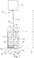
- Fig. 8 shows a field device 800 with the electronic device 601, the coupling device 801, a mounting flange 802, the standpipe 611 and the gravity weight 620, which at one of the coupling device 801 opposite end of the standpipe 611 exits the standpipe.
- the trade fair section 602 will be in Fig. 8 obscured by the standpipe 611.
- the length m of the standpipe is 980 mm, so that the gravity weight 620 20 mm protrudes from the standpipe 611.
- Fig. 8 also shows the electronic device 601 of a two-wire device.
- the electronic device 601 has at least one electronic connection 803, to which a two-wire line can be attached.
- This two-wire line can be used both for power supply and for data transmission of the electronic device 601.
- a 4 ... 20 mA signal is transmitted via the two-wire cable
- a HART signal is transmitted via the two-wire cable.
- Fig. 9 shows a side view of the field device 800 Fig. 8 , In the figure, the electronic device 601, the coupling device 801, the flange 802, the measuring cable 602 and the gravity weight 620 are illustrated. By gravity caused by the probe weight 620, the measuring cable 620 is tightened. There the standpipe 611 in Fig. 9 is omitted, the measuring cable 602 between the electronic device 601 and the gravity weight 620 can be seen.
- Fig. 10 shows a sectional view of the field device 800 Fig. 8 , wherein also the electronic device 601, the coupling device 801, the flange 802, the measuring cable 602, the standpipe 611 and the gravity weight 620 can be seen.
- FIG. 12 shows a flowchart for a method of manufacturing a probe device according to an exemplary embodiment of the present invention.
- a probe end body takes place in step S1200.
- a receiving opening for insertion of an end of a measuring cord into the probe body is made, and in step S1400 forming a wall 135, 135 'of the receiving opening 122 and / or the probe-end body 105 to form a Course of the inserted into the receiving opening 122 Meßseilendabterrorisms 102 '' 'or a Meßseilendabterrorisms 102' ' pretend.
- the shaping of the wall 135, 135 ' takes place in such a way that it spaces the measuring cable end section 102 "' inserted into the receiving opening 122 from at least one boundary 105 ', 105", 105 "', 105" 'of the probe end body 105.
- step S1500 ends in step S1500.
- the wall may be formed into a cavity 121 in the probe body 105 that adjoins the receiving opening 122.
- the adaptation of the receiving opening 122 to the cross-section of the measuring cable 102 is such that the receiving opening can be closed with the measuring cable, so that the cavity 121 can be separated from an environment is when the measuring cable is inserted into the cavity.
- the measuring cable prevents a filling material from penetrating into the interior of a probe body.
- a length of the cavity is formed such that the length is greater than the length corresponding to the perpendicular distance d, s "from the receiving opening to an opposing boundary of the probe-end body, which boundary is established, opposite the cavity Essentially, the separation of the cavity substantially prevents filling material from entering the cavity or from a measuring rope inserted into the cavity, however, the probe body may be shaped such that the probe body serves as insulation for the measuring cable, however the contents can penetrate into the interior of a gravity weight.
- a volume of the cavity is formed such that the volume is greater than the volume of a comparable cylinder having a base area which corresponds to the cross section of the receiving opening and has a length which is the vertical distance d , s "from the receiving opening to an opposing boundary of the probe body corresponds.
Description
Die vorliegende Erfindung betrifft das technische Gebiet der Messtechnik. Insbesondere betrifft die vorliegende Erfindung die Radar-, Laufzeit- oder Reflexionsmesstechnik. So beschreibt die vorliegende Erfindung eine Seilsonde, ausgeführt für ein Füllstandmessgerät, ein Füllstandmessgerät und ein Verfahren zum Herstellen einer Seilsonde.The present invention relates to the technical field of metrology. In particular, the present invention relates to radar, transit time or reflection metrology. Thus, the present invention describes a rope probe, designed for a level gauge, a level gauge and a method for producing a rope probe.
Bei Sensoren, welche nach dem Messprinzip "geführtes Radar" oder "geführte Mikrowelle" arbeiten, werden häufig Messsonden bestehend aus einem Messseil und einem Straffgewicht oder Zentriergewicht eingesetzt. Die Messsonden helfen dabei, Füllstände durch Auswertungen von Reflexionen, Laufzeiten und/oder Echos von geführten Mikrowellen oder geführten Radarwellen zu messen. Für solch eine Messung werden Wellen oder Signale angeregt, welche sich entlang einer Sonde innerhalb eines Behälters ausbreiten, und welche an markanten Stellen in dem Behälter reflektiert werden, wie beispielsweise an Übergängen zwischen unterschiedlichen Materialien. Diese Reflexionen lassen sich als Echos in einem Echodiagramm kenntlich machen. Durch das Vermessen der bei dieser Messung gewonnenen Zeitabstände der Echos kann auf die markanten Stellen, wie den Füllstand, innerhalb des Behälters zurückgeschlossen werden. Insbesondere kann ermittelt werden, ob der Behälter leer ist, d. h. ob er lediglich mit Luft gefüllt ist, oder ob sich ein Füllgut oder Schüttgut in dem Behälter befindet. Meist wird eine Füllstandmessung erst durchgeführt, wenn die Sonde das Füllgut oder Medium berührt oder in das Füllgut oder Medium eingetaucht ist. Solange die Sonde nicht im Kontakt zu dem Medium steht, dessen Füllstand ermittelt werden soll ergibt sich ein Totbereich.In the case of sensors which operate according to the measuring principle "guided radar" or "guided microwave", measuring probes consisting of a measuring cable and a gravity weight or centering weight are frequently used. The probes help to measure levels by evaluating reflections, run times and / or echoes of guided microwaves or guided radar waves. For such a measurement, waves or signals are propagated which propagate along a probe within a container and which are reflected at prominent locations in the container, such as at junctions between dissimilar materials. These reflections can be translated as echoes in one Indicate echo diagram. By measuring the time intervals of the echoes obtained during this measurement, it is possible to deduce the significant points, such as the level, within the container. In particular, it can be determined whether the container is empty, that is, whether it is only filled with air, or whether a product or bulk material is in the container. Usually, a level measurement is only performed when the probe touches the medium or medium or is immersed in the medium or medium. As long as the probe is not in contact with the medium whose level is to be determined results in a dead zone.
An einem Ende einer Seilsonde ist ein Straffgewicht angebracht. Das Straffgewicht oder Zentriergewicht dient dazu, das Messseil der Messsonde in einer möglichst stabilen Lage innerhalb eines Behälters zu halten, um ein möglichst gleichmäßiges Eintauchen des Endes des Messseils in das Füllgut zu gewährleisten.At one end of a rope probe, a gravity weight is attached. The gravity weight or centering weight serves to keep the measuring cable of the measuring probe in a stable position within a container in order to ensure the most uniform possible immersion of the end of the measuring cable into the filling material.
Eine Gewichtsvorrichtung für eine Sonde ist beispielsweise der Druckschrift
Die Druckschrift
Dokument
Dokument
Dokument
Dokument G 91 03 122 betrifft eine Füllstandsonde, welche auf dem kapazitiven Messprinzip beruht. Das Sondenseil und die Behälterwand bilden die beiden Platten eines Kondensators, wobei ein Abstand der Platten durch eine sich ausdehnende Membran verkleinert und damit die Kapazität erhöht. Die Kapazität stellt somit ein Maß für den Füllzustand der Membran dar.Document G 91 03 122 relates to a level probe, which is based on the capacitive measuring principle. The probe rope and the container wall form the two plates of a capacitor, wherein a distance of the plates by an expanding membrane decreases and thus increases the capacity. The capacity thus represents a measure of the filling state of the membrane.
Das Dokument
Es mag ein Bedarf bestehen, ein effizientes Messen von Füllständen zu ermöglichen.There may be a need to enable efficient level measurement.
Dementsprechend werden eine, Seilsonde ausgeführt für ein Füllstandmessgerät, ein Füllstandmessgerät und ein Verfahren zum Herstellen einer Seilsonde angegeben.Accordingly, a rope probe executed for a level gauge, a level gauge and a method for producing a rope probe specified.
Der Gegenstand der Erfindung ergibt sich aus den Merkmalen der unabhängigen Patentansprüche. Spezifische Ausführungsbeispiele und Weiterbildungen der Erfindung sind in den abhängigen Patentansprüchen angegeben.The object of the invention results from the features of the independent claims. Specific embodiments and further developments of the invention are indicated in the dependent claims.
Gemäß einem Aspekt der vorliegenden Erfindung wird eine Seilsonde angegeben, welche ein Messseil und eine Sondenendvorrichtung aufweist. Die Sondenendvorrichtung kann unabhängig von dem Messseil bereitgestellt werden und mag beim Herstellen der Seilsonde mit dem Messseil verbunden werden, indem sie dazu eingerichtet ist, das Messseil und insbesondere einen Messseilendabschnitt oder einen Endabschnitt des Messseils aufzunehmen, um die Seilsonde zu bilden. Das Messseil weist einen vorgebbaren Querschnitt auf. Die Sondenendvorrichtung weist einen Sondenendkörper mit einer Aufnahmeöffnung für einen Endabschnitt des Messseils auf. Die Aufnahmeöffnung weist eine Wandung auf, welche eingerichtet ist, einen Verlauf eines in die Aufnahmeöffnung eingesteckten Endabschnitts des Messseils vorzugeben. Die Wandung ist weiter eingerichtet, den in die Aufnahmeöffnung eingesteckten Endabschnitt des Messseils von zumindest einer Begrenzung oder Oberfläche des Sondenkörpers zu beabstanden.According to one aspect of the present invention, there is provided a rope probe having a measuring cord and a probe-end device. The probe-end device may be provided independently of the measuring cable and may be connected to the measuring cable during manufacture of the cable probe by being adapted to receive the measuring cable and in particular a measuring cable end section or end section of the measuring cable to form the cable probe. The measuring cable has a predeterminable cross section. The probe-end device has a probe-end body having a receiving opening for an end portion of the measuring cord. The receiving opening has a wall which is set up to predetermine a profile of an end section of the measuring cable inserted into the receiving opening. The wall is further configured to space the end portion of the measuring cable inserted into the receiving opening from at least one boundary or surface of the probe body.
Allgemein mag der Endabschnitt des Messseils oder der Messseilendabschnitt auch als Messseilende bezeichnet werden, obwohl das Messseilende eigentlich das Ende des Messeilendabschnitts, das äußerste Ende des Messseils oder das entfernte Ende des Messseils bezeichnet.Generally, the end portion of the metering rope or the end of the metering rope may also be referred to as the metering end, although the metering end is actually the end of the metering end section, the extreme end of the metering cable or the distal end of the metering cable.
In einem Beispiel mag die Seilsonde ein Messseil mit einem vorgebbaren Querschnitt aufweisen. Die Sondenendvorrichtung kann einen Sondenendkörper oder Sondenkörper mit einer Aufnahmeöffnung für einen Endabschnitt des Messseils oder für ein Messseilende aufweisen. Der Sondenendkörper weist ferner einen Hohlraum auf, der sich an die Aufnahmeöffnung anschließt. In anderen Worten ist ein Durchgang von einer Umgebung des Sondenendkörpers in das Innere des Sondenendkörpers und insbesondere in den Hohlraum des Sondenendkörpers im Wesentlichen nur durch die Aufnahmeöffnung möglich. Der Hohlraum in dem Sondenendkörper nimmt den Endabschnitt des Messseils, den Messseilendabschnitt oder das Messseilende auf, wenn das Messseil in den Sondenendkörper eingesteckt ist. Die Aufnahmeöffnung kann derart an den Querschnitt des Messseils angepasst sein, dass die Aufnahmeöffnung mit dem Messseil verschließbar oder abdichtbar ist, sodass der Hohlraum gegenüber einer Umgebung abtrennbar ist, wenn das Messseil in den Hohlraum eingesteckt ist. In anderen Worten mag die Aufnahmeöffnung derart an den Querschnitt des Messseils angepasst sein, dass durch Einstecken des Messseils in die Aufnahmeöffnung ein Abdichten des Hohlraums gegenüber einem Außenbereich ermöglicht wird.In one example, the rope probe may have a measuring cable with a predeterminable cross section. The probe-end device may include a probe-end body or probe body having a receiving opening for an end portion of the measuring cord or for a measuring cable end. The probe end body further has a cavity adjoining the receiving opening. In other words, a passage from an environment of the probe-end body into the interior of the probe-end body and in particular into the cavity of the probe-end body is possible substantially only through the receiving opening. The cavity in the probe end body receives the end portion of the measuring cord, the measuring rope end portion or the measuring cord end when the measuring cord is inserted into the probe end body. The receiving opening can be adapted to the cross section of the measuring cable such that the receiving opening can be closed or sealed with the measuring cable so that the cavity can be separated from an environment when the measuring cable is inserted into the cavity. In other words, the receiving opening may be adapted to the cross-section of the measuring cable in such a way that a sealing of the cavity with respect to an outer area is made possible by inserting the measuring cable into the receiving opening.
In einem anderen Beispiel mögen vorgebbare Messseile mit standardisierten Querschnittsflächen und Querschnittsformen existieren, sowie mit vorgebbaren Seillängen. Zu jedem dieser vorgebbaren Messseile oder Messeilformen, die durch einen Messeiltyp angegeben sein können, mag eine passende Sondenendvorrichtung existieren.In another example, predeterminable measuring cables with standardized cross-sectional areas and cross-sectional shapes may exist, as well as with predeterminable cable lengths. A suitable probe end device may exist for each of these predeterminable metering cables or fair sectional shapes, which may be indicated by a trade fair type.
Der Hohlraum ist von der Wandung der Aufnahmeöffnung ausgeformt und weist eine Länge auf, welche größer ist als die Länge, welche dem senkrechten Abstand von der Aufnahmeöffnung zu einer gegenüber angeordneten Begrenzung des Sondenkörpers entspricht. Die Begrenzung kann eine Außenfläche und/oder eine Mantelfläche des Sondenendkörpers sein. Die Begrenzung ist eingerichtet, den Hohlraum gegenüber der Umgebung im Wesentlichen abzutrennen. In einem Beispiel mag im Bereich der Aufnahmeöffnung die dickste Stelle des Sondenendkörpers sein. Der Sondenendkörper kann, wegen dieser Abtrennwirkung oder der Isolationswirkung, den einsteckenden Endabschnitt des Messseils von einer Umgebung und insbesondere von einem in der Umgebung vorhandenem Material und/oder einer Atmosphäre isolieren. So mag der Sondenendkörper einen direkten Kontakt des eingesteckten Endabschnitts des Messseils mit einer Atmosphäre oder mit einem Füllgut verhindern.The cavity is formed by the wall of the receiving opening and has a length which is greater than the length which corresponds to the vertical distance from the receiving opening to an opposing boundary of the probe body. The boundary may be an outer surface and / or a lateral surface of the probe end body. The boundary is designed to substantially separate the cavity from the environment. In one example, in the area of the receiving opening the thickest part of the Be probe end body. The probe end body can, because of this separation effect or the insulating effect, the spigot end portion of the measuring cable of a Isolate environment and in particular from a material present in the environment and / or an atmosphere. Thus, the probe end body may prevent a direct contact of the inserted end portion of the measuring cable with an atmosphere or with a filling material.
Der vorgebbare Querschnitt kann jede beliebige Form aufweisen, beispielsweise eine Kreisform mit einer runden Querschnittsfläche. Der Querschnitt, für den die Aufnahmeöffnung vorgesehen ist, mag die Querschnittsfläche der Aufnahmeöffnung bestimmen.The predeterminable cross-section may have any shape, for example a circular shape with a circular cross-sectional area. The cross-section for which the receiving opening is provided may determine the cross-sectional area of the receiving opening.
Nach dem Einführen des Messseils in den Hohlraum, kann der Hohlraum ganz oder teilweise mit dem Messseil ausgefüllt sein. Um ein Aufschwimmen eines mit Luft gefülltem Sondenendkörpers zu verhindern, kann derjenige Hohlraum, der nicht von dem Messseil ausgefüllt wird, von einem Füllmaterial mit hoher Dichte aufgefüllt sein. Dieses Füllmaterial kann beispielsweise eine große Masse aufweisen, um das Gewicht des Sondenendkörpers zu erhöhen. Der Hohlraum mag ein Volumen aufweisen, das gleich oder größer ist als das Volumen, welches den eingesteckten Endabschnitt des Messseils oder den eingesteckten Messeilendabschnitt aufweist.After insertion of the measuring cable into the cavity, the cavity can be completely or partially filled with the measuring cable. In order to prevent floating of a probe body filled with air, the cavity, which is not filled by the measuring cable, can be filled by a high-density filling material. For example, this filler may have a large mass to increase the weight of the probe body. The cavity may have a volume equal to or greater than the volume having the inserted end portion of the measuring cable or the inserted Messeilendabschnitt.
Die Länge und die Querschnittsfläche des Messseils bestimmen das notwendige Mindestvolumen des Hohlraums. Unter der Voraussetzung, dass sich die Querschnittsfläche des eingesteckten Messseils im Inneren des Sondenkörpers nicht verjüngt sondern konstant bleibt oder sich vergrößert, mag das Mindestvolumen des Hohlraums durch die einzusteckende Länge des Messseilendabschnitts und die Querschnittsfläche des Messseils vorgegeben sein, wobei das Mindestvolumen mindestens notwendig ist, um den Messseilendabschnitt aufzunehmen.The length and the cross-sectional area of the measuring cable determine the necessary minimum volume of the cavity. Provided that the cross-sectional area of the inserted measuring cable inside the probe body does not taper but remains constant or increases, the minimum volume of the cavity may be predetermined by the length of the measuring cable end section to be inserted and the cross-sectional area of the measuring cable, the minimum volume being at least necessary. to pick up the measuring cable end section.
Da die Länge des eingesteckten Messeilendabschnitts länger sein soll als die Länge, die einer Dicke des Sondenendkörpers entspricht, mag der Hohlraum für ein Messseil mit rundem Querschnitt ein Volumen aufweisen, welches größer ist, als das Volumen eines Zylinders mit einer Grundfläche, welche dem Querschnitt der Aufnahmeöffnung entspricht, und einer Länge, welche dem senkrechten Abstand von der Aufnahmeöffnung zu einer gegenüber angeordneten Begrenzung des Sondenkörpers entspricht.Since the length of the inserted fairing end portion should be longer than the length corresponding to a thickness of the probe end body, the cavity for a measuring wire having a round cross section may have a volume which is larger than that Volume of a cylinder having a base area which corresponds to the cross-section of the receiving opening, and a length which corresponds to the vertical distance from the receiving opening to an opposite boundary of the probe body.
Gemäß der vorliegenden Erfindung weist die Seilsonde ein Messseil auf, welches zum Führen einer Mikrowelle oder einer Radarwelle ausgeführt ist.According to the present invention, the rope probe has a measuring cable, which is designed for guiding a microwave or a radar wave.
Im eingesteckten Zustand, in dem das Messseil in die Aufnahmeöffnung eingesteckt ist, mag die Wandung der Aufnahmeöffnung den Verlauf des Messseils bestimmen. Insbesondere mag die Wandung des Sondenendkörpers und insbesondere die Wandung der Aufnahmeöffnung so ausgebildet sein, dass sie einen Verlauf des Messeilendabschnitts vorgibt. Die Wandung mag dafür sorgen, dass der Verlauf des Messseilendabschnitt vorgebbar wird und nicht seinem natürlichen Verlauf folgt, den es beispielsweise bei Einwirkung der Schwerkraft einnehmen würde. Die Wandung mag dafür sorgen, dass der Messeilendabschnitt gegenüber einer vorgebbaren Außenfläche des Sondenendkörpers beabstandet wird. So mag die Wandung des Sondenendkörpers als Isolator genutzt werden können. Beispielsweise mag ein von der unteren Oberfläche beabstandetes Messseil daran gehindert werden, mit einer Metalloberfläche eines unter der unteren Oberfläche angeordneten Behälterbodens in Kontakt zu gelangen.In the inserted state, in which the measuring cable is inserted into the receiving opening, the wall of the receiving opening may determine the course of the measuring cable. In particular, the wall of the probe end body and in particular the wall of the receiving opening may be formed such that it predetermines a course of the exhibition end section. The wall may ensure that the course of the Meßseilendabschnitt is specifiable and does not follow its natural course, which it would take, for example, by the action of gravity. The wall may ensure that the fairing end portion is spaced from a predeterminable outer surface of the probe end body. Thus, the wall of the probe body may be used as an insulator. For example, a measuring wire spaced from the lower surface may be prevented from coming into contact with a metal surface of a container bottom disposed below the lower surface.
In einem Beispiel kann mittels des eingesteckten Messseils der Hohlraum oder Innenraum des Sondenendkörpers abgedichtet werden. Der Hohlraum mag ferner in dem eingesteckten Zustand ganz oder teilweise von dem Messseilendabschnitt ausgefüllt sein. Die Aufnahmeöffnung des Sondenendkörpers kann in einem Beispiel so an den Querschnitt des Messseils angepasst sein, dass sich beim Einstecken des Messseils in die Aufnahmeöffnung eine Presspassung ergibt. Eine solche Presspassung kann beispielsweise dadurch erzeugt werden, dass der Querschnitt der Aufnahmeöffnung kleiner als der Querschnitt des Messseils ist. Die Presspassung kann durch temporäres Erwärmen vor dem Einstecken des Messseils in die Aufnahmeöffnung der Sondenendvorrichtung hergestellt werden und dafür sorgen, dass das Messseilende durch Reibkräfte von der Aufnahmeöffnung und/oder von der Hohlraumwandung im Inneren der Sondenendvorrichtung gehalten wird.In one example, the cavity or interior of the probe body can be sealed by means of the inserted measuring cable. The cavity may also be in the inserted state wholly or partly from the Meßseilendabschnitt filled out. In one example, the receiving opening of the probe end body can be adapted to the cross section of the measuring cable such that a press fit results when the measuring cable is inserted into the receiving opening. Such a press fit can be produced, for example, by the cross section of the receiving opening being smaller than the cross section of the measuring cable. The interference fit may be made by temporarily heating prior to insertion of the measuring cable into the receiving opening of the probe-end device and ensuring that the measuring cable end is held by friction forces from the receiving opening and / or the cavity wall in the interior of the probe end device.
Gemäß einem weiteren Aspekt der vorliegenden Erfindung wird ein Füllstandmessgerät beschrieben. Das Füllstandmessgerät weist eine Elektronikeinrichtung und die erfindungsgemäße Seilsonde auf. Die Elektronikeinrichtung ist mit dem Messseil verbunden und zum Senden und/oder zum Empfangen einer elektromagnetischen Welle ausgebildet. In einem Beispiel kann die Elektronikeinrichtung auch eine Auswerteeinrichtung aufweisen, um beispielsweise eine Messkurve oder Echokurve aus den gesendeten und/oder empfangenen Signalen zu erzeugen und auszuwerten. Zum Auswerten der Echokurve mag die Elektronikeinrichtung, insbesondere die Auswerteeinrichtung, Methoden der digitalen Signalverarbeitung anwenden und beispielsweise aus einer gemessenen Laufzeit eine Füllstandhöhe berechnen und zur Anzeige bringen. Gemäß einem anderen Aspekt der vorliegenden Erfindung wird ein Verfahren zum Herstellen der erfindungsgemäßen Seilsonde angegeben. Das Verfahren weist das Bereitstellen eines Sondenendkörpers und das Erstellen einer Aufnahmeöffnung für das Einstecken eines Endabschnitts eines Messseils in den Sondenendkörper auf. Ferner weist das Verfahren das Formen einer Wandung der Aufnahmeöffnung und/oder des Sondenendkörpers derart auf, dass die Wandung einen Verlauf des in die Aufnahmeöffnung eingesteckten Messseilendabschnitts vorgeben kann. Die Wandung wird auch derart geformt, dass sie den in die Aufnahmeöffnung eingesteckten Messseilendabschnitt von zumindest einer Begrenzung, einer Oberfläche und oder einer Mantelfläche des Sondenendkörpers beabstandet.In accordance with another aspect of the present invention, a level gauge is described. The level gauge has an electronic device and the rope probe according to the invention. The electronic device is connected to the measuring cable and designed for transmitting and / or receiving an electromagnetic wave. In one example, the electronic device may also have an evaluation device in order to generate and evaluate, for example, a measurement curve or echo curve from the transmitted and / or received signals. For evaluating the echo curve, the electronic device, in particular the evaluation device, may use methods of digital signal processing and, for example, calculate a level height from a measured transit time and display it. According to another aspect of the present invention, there is provided a method of making the rope probe of the invention. The method includes providing a probe end body and creating a receiving opening for insertion of an end portion of a measuring cord into the probe body. Furthermore, the method comprises forming a wall of the receiving opening and / or the probe end body such that the wall can predetermine a course of the measuring cable end section inserted into the receiving opening. The Wall is also shaped such that it spaced from the measuring cable end portion inserted into the receiving opening of at least one boundary, a surface and or a lateral surface of the probe end body.
In einem Beispiel weist das Verfahren das Erstellen des erfindungsgemäß vorhandenen Hohlraums in dem Sondenendkörper auf, wobei sich der Hohlraum an die Aufnahmeöffnung anschließt. Außerdem weist das Verfahren das Anpassen der Aufnahmeöffnung an den Querschnitt des Messseils derart auf, dass die Aufnahmeöffnung mittels dem Messseil verschließbar oder abdichtbar ist und dass der Hohlraum gegenüber einer Umgebung abtrennbar ist, wenn das Messseil in den Hohlraum eingesteckt ist.In one example, the method comprises creating the cavity present in the probe-end body according to the invention, wherein the cavity adjoins the receiving opening. In addition, the method comprises adapting the receiving opening to the cross section of the measuring cable such that the receiving opening can be closed or sealed by means of the measuring cable and that the cavity can be separated from an environment when the measuring cable is inserted into the cavity.
Ferner kann das Verfahren beispielsweise das Ausbilden einer Länge des erfindungsgemäß vorhandenen Hohlraums aufweisen, welche größer ist als die Länge, welche dem senkrechten Abstand von der Aufnahmeöffnung zu einer gegenüber angeordneten Begrenzung des Sondenkörpers entspricht. Die Begrenzung und insbesondere die Wandung zwischen Begrenzung und Hohlraum ist eingerichtet, den Hohlraum gegenüber der Umgebung und/oder gegenüber einem in der Umgebung vorhandenem Füllgut im Wesentlichen abzutrennen. Bei der Begrenzung kann es sich um eine äußere Oberfläche oder um eine Mantelfläche des Sondenendkörpers handeln.Furthermore, the method may, for example, comprise the formation of a length of the cavity according to the invention which is greater than the length which corresponds to the vertical distance from the receiving opening to an opposing boundary of the probe body. The boundary and in particular the wall between the boundary and the cavity is designed to substantially separate the cavity from the environment and / or from a filling material present in the environment. The boundary may be an outer surface or a lateral surface of the probe body.
In einem Beispiel weist das Verfahren das Ausbilden eines Volumens des Hohlraums derart auf, dass das Volumen größer ist als das Volumen eines virtuellen Zylinders oder Vergleichszylinders, mit einer Grundfläche, welche dem Querschnitt der Aufnahmeöffnung entspricht, und mit einer Länge, welche dem senkrechten Abstand von der Aufnahmeöffnung zu einer gegenüber angeordneten Begrenzung des Sondenendkörpers entspricht, wobei die Begrenzung eingerichtet ist, den Hohlraum gegenüber der Umgebung im Wesentlichen abzutrennen.In one example, the method comprises forming a volume of the cavity such that the volume is greater than the volume of a virtual cylinder or comparative cylinder having a footprint corresponding to the cross-section of the receiving aperture and having a length which is the perpendicular distance of the receiving opening corresponds to an opposing boundary of the probe end body, wherein the limit is arranged to substantially separate the cavity from the environment.
Ferner mag ein computerlesbares Speichermedium angegeben werden, welches einen Programmcode aufweist, der, wenn er von einem Prozessor ausgeführt wird, das Verfahren zum Herstellen einer Sondenendvorrichtung oder Sondenvorrichtung ausführt.Furthermore, a computer-readable storage medium may be indicated which has a program code which, when executed by a processor, the Process for producing a probe-end device or probe device performs.
Darüber hinaus mag ein Computerprogrammprodukt angegeben sein, welches einen Programmcode enthält, der, wenn er von einem Prozessor ausgeführt wird, den Prozessor dazu anleitet, das Verfahren zur Herstellung einer Sondenvorrichtung auszuführen.In addition, a computer program product may be indicated which includes program code which, when executed by a processor, directs the processor to perform the method of manufacturing a probe device.
Beispielsweise mag es sich bei dem Programmcode um Anweisungen für eine CNC-Maschine (Computerized Numerical Control) oder für einen 3D-Drucker handeln.For example, the program code may be instructions for a computerized numerical control (CNC) machine or for a 3D printer.
In Sensoren, welche nach dem Messprinzip "geführtes Radar" oder "geführte Mikrowelle" arbeiten, werden häufig Messsonden oder Sondenvorrichtungen eingesetzt, welche ein Messseil und ein Straffgewicht, Zentriergewicht oder eine Sondenendvorrichtung aufweisen. Durch das bei Seilmesssonden oder bei einer entsprechenden Sondenvorrichtung zum Straffhalten des Seiles benutzte Sondengewicht kann es zu Störungen von Messungen im Bereich eines Sondenendes kommen, welches mit dem Sondengewicht verbunden ist. Zu Messstörungen kann es im Bereich eines Sondenendes kommen, welches einem Ende eines Messseils gegenüber liegt, welches Ende mit einer Elektronikeinrichtung verbunden ist. Die Störungen können durch Inhomogenitäten an dem Übergang von dem Messseil zu dem Sondengewicht hervorgerufen werden, die beispielsweise durch das Anbringen des Gewichtes an dem freien Sondenende entstehen. Störend kann sich beispielsweise eine abrupte Verdickung im Übergangsbereich von dem Querschnitt des Messseils zu dem Querschnitt des Sondengewichts auswirken, welche Verdickung vorgesehen wird, um ein möglichst hohes Gewicht am Sondenende zu erzeugen, insbesondere wenn das Sondengewicht massiv aus Vollmaterial ausgebildet ist. Ein inhomogener Übergang oder eine Verdickung oder eine Verformung kann das HF (Hochfrequenz)-Verhalten einer Messsonde dahingehend beeinflussen, dass ungewünschte Störechos auftreten. Störungen können aber auch entstehen, wenn das Messseil mit einem ungewünschten anderen Objekt in Berührung kommt, beispielsweise mit einer Behälterwand.In sensors which operate according to the measuring principle "guided radar" or "guided microwave", measuring probes or probe devices are frequently used, which have a measuring cable and a gravity weight, centering weight or a probe end device. The probe weight used with rope probes or with a corresponding probe device for keeping the rope tight may cause interference with measurements in the area of a probe end which is connected to the probe weight. Measuring interference can occur in the region of a probe end, which lies opposite an end of a measuring cable, which end is connected to an electronic device. The disturbances can be caused by inhomogeneities at the transition from the measuring cable to the probe weight, which result, for example, from the attachment of the weight to the free end of the probe. Disturbing, for example, an abrupt thickening in the transition region from the cross section of the measuring cable to the cross section of the probe weight effect, which thickening is provided to produce the highest possible weight at the probe end, especially when the probe weight is solid made of solid material. An inhomogeneous transition or thickening or deformation can affect the RF (Radio Frequency) behavior of a probe so that unwanted clutter occurs. But disturbances can also arise when the measuring cable comes into contact with an undesired other object, for example with a container wall.
Ein Störecho mag ein Echo sein, welches in einer gemessenen Echokurve sichtbar ist, welches jedoch nicht mit einem gewünschten Messobjekt im Zusammenhang steht, wie beispielsweise mit dem Füllstand oder mit dem Übergang zwischen unterschiedlichen Materialien. Ein Nutzecho ist hingegen ein Echo, welches von einer Inhomogenität erzeugt wird, deren Eigenschaft oder Lage von Interesse ist. Ein Nutzecho ist beispielsweise ein Echo, das von einem Füllstand oder von einer Grenzfläche zwischen zwei oder mehreren Materialien herrührt.An interference echo may be an echo which is visible in a measured echo curve, but which is not related to a desired measurement object, such as the level or transition between different materials. By contrast, a useful echo is an echo which is generated by an inhomogeneity whose property or position is of interest. A useful echo, for example, is an echo that results from a level or an interface between two or more materials.
Das Störecho wird zu einem störenden Faktor, wenn es einen Einfluß auf das interessante Nutzecho hat. Störechos, die in weiter Entfernung von dem Nutzecho liegen können deutlich von einem Nutzecho unterschieden werden.The false echo becomes a disturbing factor when it has an influence on the interesting useful echo. False echoes that lie far away from the useful echo can be distinguished clearly from a useful echo.
Eine weitere Form von Echo ist ein Echo, welches am Ende des Messseils und insbesondere am entferntesten oder äußersten Ende des Messseils entsteht, d.h. am im Wesentlichen offenen Ende des Messeilendabschnitts. Dieses Endeecho kann einerseits genutzt werden das Ende des Messseils in einer Echokurve zu identifizieren und kann daher als Nutzecho qualifiziert werden. Andererseits kann es sich jedoch auf ein von dem Füllstand hervorgerufenes Nutzecho auswirken und damit die Erkennung des Nutzechos stören. Somit kann das Endeecho einen nützlichen und einen störenden Effekt haben.Another form of echo is an echo which arises at the end of the measuring cable and in particular at the farthest or outermost end of the measuring cable, i. E. at the substantially open end of the Messeilendabschnitts. This end echo can be used on the one hand to identify the end of the measuring cable in an echo curve and can therefore be qualified as a true echo. On the other hand, it may, however, have an effect on the level of echo caused by the fill level and thus interfere with the detection of the wanted echo. Thus, the end echo can have a useful and a disturbing effect.
Insbesondere wenn der Füllstand im Bereich des Messseilendes liegt und das Messseil im Wesentlichen senkrecht verläuft, kann es zu der störenden Wirkung des Endeechos kommen. Gerade bei niedrigen Füllständen liegen das Endeecho und das Füllstandecho nahe beisammen, so dass ein Totbereich entstehen kann, in dem das Endeecho einen so großen Einfluss auf das Füllstandecho hat, dass eine Füllstandmessung nicht möglich ist. Der Totbereich kann in einer Größenordnung von 90 mm liegen, so dass bei einer Verwendung solch einer Messsonde unter der Annahme der Ausnutzung der gesamten Behälterhöhe als Messeillänge trotzdem nur ein Füllstand über 90mm vom Behälterboden bestimmbar ist. Es mag erwünscht sein, eine Seilsonde mit einem möglichst geringen Totbereich zu schaffen.In particular, when the level is in the range of Messseilendes and the measuring cable is substantially perpendicular, it can lead to the disturbing effect of the tail echo. Especially at low levels, the end echo and the level echo are close together, so that a dead zone can arise in which the end echo has such a large influence on the level echo that a level measurement is not possible. The dead area can be of an order of magnitude of 90 mm, so that when using such a probe under the assumption of the utilization of the entire container height as a fair length anyway only a level above 90mm from the bottom of the container can be determined. It may be desirable to provide a rope probe with as little dead zone as possible.
Ein Totbereich mag die Länge eines Messseilendabschnitts bezeichnen, die mindestens notwendig ist, um einen ausreichend langen Endabschnitt eines Messseils zu erzeugen, sodass das an dem entfernten Ende des Messseils entstehende Störecho nicht ein von dem Füllstand hervorgerufenes Nutzecho beeinflusst, zuzüglich einer Länge, die von einem Behälterboden bis zu dem entfernten Messeilende reicht. In anderen Worten mag ein Totbereich von 90 mm bedeuten, dass das Ende einer Messsonde mindestens 90 mm in das Füllgut eintauchen muss, um ein Nutzecho zu erzeugen, welches von dem Störecho unterschieden werden kann, das von dem Sondenende hervorgerufen wird. Diese Annahme sollte insbesondere dann erfüllt sein, wenn es sich bei dem Füllgut um ein schwach reflektierendes Material handelt.A dead zone may denote the length of a measuring cable end portion which is at least necessary to produce a sufficiently long end portion of a measuring cable so that the false echo generated at the distal end of the measuring cable will not affect a useful echo produced by the level plus a length equal to a Tank bottom reaches to the far end of the fair. In other words, a dead band of 90 mm may mean that the end of a probe must dip at least 90 mm into the contents to produce a useful echo, which can be distinguished from the clutter caused by the probe end. This assumption should be fulfilled, in particular, when the filling material is a poorly reflecting material.
Bei einer geraden Führung des Messseils entsteht das Endeecho im Wesentlichen in einer Distanz zu der Elektronikeinrichtung oder Einkoppeleinrichtung, welche der Sondenlänge entspricht, die von der Messseillänge und/oder der Länge der Sondenendvorrichtung oder des Sondengewichts bestimmt wird. Durch konstruktive Varianten und Formungen des Sondengewichts können die Störeinflüsse, der von den Störstellen hervorgerufenen Störechos minimiert werden, sodass ein gewünschtes Nutzecho deutlicher von einem Störecho unterscheidbar ist. Um das Sondengewicht konstruktiv zu verändern, können Sondengewichte unterschiedlicher Länge, unterschiedlicher Durchmesser und unterschiedlicher Massen genutzt werden. Jedoch mag sich selbst durch die Variation der Form der Sondengewichte bei schwach reflektierenden Füllgütern lediglich ein Totbereich in der Größenordnung von 90 mm erreichen lassen.In the case of a straight guide of the measuring cable, the end echo essentially arises at a distance to the electronic device or coupling device which corresponds to the probe length determined by the measuring cable length and / or the length of the probe transmitting device or the probe weight. Constructive variants and shaping of the probe weight can minimize the interference caused by the impurities caused by false echoes, so that a desired useful echo is more distinct from a false echo. In order to modify the probe weight constructively, probe weights of different lengths, different diameters and different masses can be used. However, even by varying the shape of the probe weights in low-reflectance fillers, only a deadband on the order of 90 mm may be achieved.
Es mag daher als ein Aspekt der Erfindung betrachtet werden, bei geringer Eintauchtiefe in ein Füllgut, insbesondere bei einer Eintauchtiefe von weniger als 90 mm einen großen Abstand zwischen Eintauchstelle, also dem Füllstand, und dem Sondenende herbeizuführen. In anderen Worten mag es gewünscht sein, das Ende eines Messseils, und damit das von dem entfernten Ende des Messseils hervorgerufene Störecho, möglichst weit von einer Stelle zu entfernen, bei der ein Messseil in das Füllgut eintaucht. Bei diesem Entfernen mag jedoch zu beachten sein, dass das Messeil nicht mit einer Behälterwandung in Berührung kommt. Die erfindungsgemäße Sondenendvorrichtung soll daher so beschaffen sein, dass der Abstand zwischen dem entfernten Messseilende und einer Eintauchposition in ein Füllgut künstlich verlängert wird. Trotz der Verlängerung des Abstandes wird das Messeilende von einer Störstelle ferngehalten oder isoliert, beispielsweise von einer Behälterwandung. Durch die künstliche Verlängerung kann die in der Echokurve dargestellte Position des am entfernten Messeilende auftretenden Störechos von der Position des Nutzechos, das durch die Grenzfläche des Füllstandes hervorgerufenen wird, so weit auseinander gezogen werden, dass sich die beiden Echos in der Echokurve im Wesentlichen nicht beeinflussen. Für das Auseinanderziehen mag der physikalische Effekt ausgenutzt werden, dass sich die geführte elektromagnetische Welle im Wesentlichen unabhängig von der Form des Messseils entlang des Messseils ausbreitet und die für diese Ausbreitung benötigte Laufzeit als Grundlage für eine in der Echokurve dargestellte Position eines Echos genutzt wird.It may therefore be regarded as an aspect of the invention to bring about a large distance between immersion point, that is to say the filling level, and the probe end with a small immersion depth into a filling material, in particular with an immersion depth of less than 90 mm. In other words, it may be desirable to remove the end of a measuring cable, and thus the interference echo caused by the remote end of the measuring cable, as far as possible from a point at which a measuring cable dips into the filling material. However, care should be taken when removing this that the fairing does not come into contact with a container wall. The probe end device according to the invention should therefore be such that the distance between the remote end of the measuring cable and an immersion position in a filling material is artificially prolonged. Despite the extension of the distance, the fairing end is kept away from or isolated from an impurity, for example from a container wall. Due to the artificial extension, the position shown in the echo curve of the false echo occurring at the remote end of the fair from the position of the useful echo, which is caused by the interface of the level, can be pulled so far apart that affect the two echoes in the echo curve substantially , For the pulling apart, the physical effect may be exploited that the guided electromagnetic wave propagates substantially independently of the shape of the measuring cable along the measuring cable and the travel time required for this propagation is used as the basis for a position of an echo represented in the echo curve.
Eine Verlängerung des Messseils ohne den Behälterboden und/oder ohne eine Behälterwandung zu berühren kann dadurch erreicht werden, dass der Messseilendabschnitt möglichst weit innerhalb einer Sondenendvorrichtung, insbesondere innerhalb eines Straffgewichts und/oder innerhalb eines Zentriergewichts verstaut wird. Der Sondenendkörper der Sondenendvorrichtung mag so eingerichtet sein, dass er den Verlauf des Messseilendabschnitts vorgeben kann und/oder den Messseilendabschnitt gegenüber einer Störstelle isoliert oder beabstandet.An extension of the measuring cable without touching the container bottom and / or without a container wall can be achieved by stowing the measuring cable end section as far as possible within a probe end device, in particular within a tight weight and / or within a centering weight. The probe-end body of the probe-end device may be arranged to predetermine the course of the measuring-cable end portion and / or to isolate or space the measuring-cable end portion from an impurity.
In einem Beispiel mag der Sondenendkörper so eingerichtet sein, dass das Füllgut zumindest teilweise mit dem eingesteckten Messseil in Kontakt treten kann. In einem anderen Beispiel mag der Sondenendkörper der Sondenendvorrichtung für das Aufnehmen des Messseilendabschnitts so eingerichtet sein, dass der Verlauf des Messseils vorgebbar ist, und dass der Sondenendkörper das Messseil gegenüber der Umgebung und insbesondere gegenüber dem Füllgut und/oder gegenüber einem Behälterboden im Wesentlichen abgetrennt, beabstandet oder isoliert.In one example, the probe end body may be arranged so that the contents can at least partially come into contact with the inserted measuring cable. In another example, the probe end body of the probe end device for receiving the Meßseilendabschnitts may be set so that the course of the measuring cable is predetermined, and that the probe end body the measuring cable relative to the environment and in particular against the contents and / or compared to a container bottom substantially separated, spaced or isolated.
Gemäß einem Aspekt der vorliegenden Erfindung bildet die Wandung einen Hohlraum innerhalb des Sondenendkörpers aus, wobei sich der Hohlraum an die Aufnahmeöffnung anschließt. Die Aufnahmeöffnung ist derart an den Querschnitt des Messseils angepasst, dass die Aufnahmeöffnung mit dem Messseil verschließbar ist, so dass der Hohlraum gegenüber einer Umgebung abtrennbar ist, wenn das Messseil in dem Hohlraum eingesteckt ist. Der Hohlraum weist eine Länge auf, welche größer ist als die Länge des senkrechten Abstands von der Aufnahmeöffnung zu einer gegenüber der Aufnahmeöffnung angeordneten Begrenzung des Sondenendkörpers. Die Begrenzung ist eingerichtet, den Hohlraum gegenüber der Umgebung im Wesentlichen abzutrennen. Die Begrenzung mag in einem Beispiel die Oberfläche des Sondenendkörpers sein.In accordance with one aspect of the present invention, the wall defines a cavity within the probe body, with the cavity adjacent to the receiving opening. The receiving opening is adapted to the cross-section of the measuring cable such that the receiving opening can be closed with the measuring cable, so that the cavity can be separated from an environment when the measuring cable is inserted in the cavity. The cavity has a length which is greater than the length of the vertical distance from the receiving opening to a opposite the receiving opening arranged boundary of the probe end body. The boundary is designed to substantially separate the cavity from the environment. The boundary, in one example, may be the surface of the probe body.
Dadurch, dass der Hohlraum mittels des Messseils verschließbar ist, kann ein Füllgut von dem Messseil ferngehalten werden, wodurch die Ausbreitung einer von dem Messseil geführten elektromagnetischen Welle im Wesentlichen nicht von dem Füllgut beeinflusst wird.Because the cavity can be closed by means of the measuring cable, a filling material can be kept away from the measuring cable, as a result of which the propagation of an electromagnetic wave guided by the measuring cable is substantially not influenced by the product.
Gemäß einem anderen Aspekt der vorliegenden Erfindung sind der Sondenkörper, die Wandung und/oder der Hohlraum in dem Sondenkörper derart eingerichtet, dass durch den Sondenkörper und/oder durch den Hohlraum eine Verlaufsform des eingesteckten Messseilendabschnitts vorgebbar ist.According to another aspect of the present invention, the probe body, the wall and / or the cavity in the probe body are arranged such that a shape of the inserted Meßseilendabschnitts is predeterminable by the probe body and / or through the cavity.
Da das Messseil und insbesondere eine Messsonde möglichst die gesamte Länge im Inneren eines Behälters erfassen soll, mag die Länge des Messseils so gewählt sein, dass sie im Wesentlichen der Behälterhöhe entspricht. Dadurch mag ein frei bewegliches Sondenende nahe an einem Behälterboden positioniert werden. Das Messseil kann aus Drahtgeflecht oder einem anderen flexiblen hergestellt sein. Folglich würde sich der Messseilendabschnitt möglichst lange erstrecken, wenn das Ende frei der Schwerkraft überlassen wird.Since the measuring cable and in particular a measuring probe should detect as far as possible the entire length in the interior of a container, the length of the measuring cable may be selected such that it substantially corresponds to the container height. As a result, a freely movable probe end may be positioned close to a container bottom. The measuring cable can be made of wire mesh or another flexible. Consequently, the measuring cable end portion would extend as long as possible, when the end is left free to the force of gravity.
Durch den Hohlraum und/oder durch die Wandung in der Sondenendvorrichtung kann sich der Verlauf eines sonst losen Endes jedoch derart beeinflussen lassen, dass das Ende von der Begrenzung des Sondenendkörpers und somit auch von dem Behälterboden ferngehalten, beabstandet oder isoliert wird. Es wird durch die Beeinflussung des Verlaufes verhindert, dass das Messseilende die gesamte Länge eines Behälters ausfüllt, wie es bei einem unkontrollierten Aussetzen des Messseilendes der Schwerkraft der Fall wäre. Die Sondenendvorrichtung bildet eine Plattform, die den Messseilendabschnitt vom Behälterboden und/oder von einer Behälterwandung fern hält oder isoliert und deren Gewicht gleichzeitig zur Straffung des übrigen Messseils beiträgt. So kann auch ein Verlauf des Messseilendabschnitts erzeugt werden, der parallel zu einem Behälterboden oder auch entgegen der Schwerkraft gerichtet ist. Auf diese Art und Weise mag es möglich sein, den Endabschnitt eines Messseils zu verlängern, ohne dass es an den durch die Behälterhöhe vorgegebenen Behälterboden anstößt, aber dennoch länger als die Behälterhöhe ist. Die Sondenendvorrichtung mag es ermöglichen, dass ein außerhalb der Sondenendvorrichtung angeordneter Messeilabschnitt von dem Gewicht der Sondenendvorrichtung und/oder dem darin liegendem Messseilendabschnitt straff gespannt wird, während der innerhalb der Sondenendvorrichtung verlaufende Endabschnitt des Messseils ungespannt oder schlaff ist.Through the cavity and / or through the wall in the probe end device, however, the course of an otherwise loose end can be influenced such that the end of the boundary of the probe body and thus also kept away from the container bottom, spaced or isolated. It is prevented by influencing the course that the Meßseilende fills the entire length of a container, as would be the case in an uncontrolled exposure of the measuring cable end of gravity. The probe end device forms a platform which keeps the Meßseilendabschnitt away from the container bottom and / or from a container wall or isolated and their weight simultaneously contributes to the tightening of the remaining measuring cable. Thus, a course of the Meßseilendabschnitts can be generated, which is directed parallel to a container bottom or against gravity. In this way it may be possible to extend the end section of a measuring cable without it abutting the container bottom defined by the container height, but nevertheless being longer than the container height. The probe-end device may allow a fairing portion disposed outside the probe-end device to be taut by the weight of the probe-end device and / or the measuring-wire end portion therein while the end portion of the measuring-wire extending within the probe-end device is unstressed or slack.
Gemäß einem anderen Aspekt der vorliegenden Erfindung weist der Hohlraum eine Länge und den Querschnitt der Aufnahmeöffnung auf, wobei der Querschnitt des Hohlraums über die gesamte Länge des Hohlraums dem Querschnitt der Aufnahmeöffnung entspricht.According to another aspect of the present invention, the cavity has a length and the cross section of the receiving opening, wherein the cross section of the cavity over the entire length of the cavity corresponds to the cross section of the receiving opening.
Auf diese Art und Weise mag der Hohlraum im Wesentlichen dem Verlauf des Messseilendabschnitts entsprechen und kann die Form des Messseilendabschnitts beeinflussen, ohne einen mit Luft gefüllten Hohlraum zu erzeugen, der nur ein geringes Gewicht für den Sondenendkörper erzeugt. Beispielsweise kann der gesamte Hohlraum als Presspassung ausgebildet sein, sodass der Hohlraum alleine eine so gute Befestigung für den Messseilendabschnitt ausbilden kann, dass eine Befestigungseinrichtung am entfernten Ende des Messseils nicht nötig ist.In this way, the cavity may substantially conform to the course of the metering end section and may affect the shape of the metering end section without creating an air-filled cavity that produces only light weight for the probe end body. For example, the entire cavity can be formed as a press fit, so that the cavity alone can form such a good attachment for the Meßseilendabschnitt that a fastening device at the distal end of the measuring cable is not necessary.
Alternativ kann auch mehr Material des Sondenkörpers entnommen sein, als für die Unterbringung des Messseilendabschnitts notwendig ist, und der Messseilendabschnitt befindet sich lose innerhalb des Hohlraums, sodass der Messseilendabschnitt zwar im Wesentlichen nur durch die von der Aufnahmeöffnung gebildete Presspassung im Inneren des Sondenkörpers gehalten wird, jedoch die Form des Verlaufs des Messseilendabschnitt im Inneren des Hohlraums nicht vorgegeben ist.Alternatively, more material may be taken from the probe body than is necessary to accommodate the measuring cable end portion, and the measuring cable end portion is loosely located within the cavity so that the measuring cable end portion is held within the probe body substantially only by the interference fit formed by the receiving aperture. however, the shape of the course of the Meßseilendabschnitt is not predetermined in the interior of the cavity.
Gemäß einem anderen Aspekt der vorliegenden Erfindung weist der Sondenkörper ein vorgebbares Gewicht auf. In Abhängigkeit von dem Einsatz des Sondenkörpers, insbesondere in Abhängigkeit von der Dichte des zu messenden Füllgutes, mag eine mehr oder weniger schwere Sondenendvorrichtung benötigt werden. Das Gewicht der Sondenendvorrichtung kann durch die Größe des Hohlraums aber auch durch die Größe des Sondenkörpers und/oder die Dichte des Materials des Sondenkörpers beeinflusst werden, sodass für verschiedene Messseile und verschiedene Einsatzzwecke verschieden schwere Sondenendvorrichtungen bereitgestellt werden können.According to another aspect of the present invention, the probe body has a predeterminable weight. Depending on the use of the probe body, in particular as a function of the density of the substance to be measured, a more or less severe probe end device may be required. The weight of the probe-end device can be influenced by the size of the cavity but also by the size of the probe body and / or the density of the material of the probe body, so that differently sized probe end devices can be provided for different measuring cables and different applications.
Gemäß der vorliegenden Erfindung ist der Hohlraum L-förmig, U-förmig, und/oder schneckenförmig ausgebildet. Diese unterschiedlichen Formen des Hohlraums erlauben es, den Messseilendabschnitt von einer lotrechten Position, die zum Anstoßen des Messseilendes an einen Behälterboden führen könnte, abweichen zu lassen und eine andere Raumrichtung für die Verlängerung des Messseilendabschnitts zu verwenden. Beispielsweise mag sich der Messseilendabschnitt durch einen schneckenförmig ausgebildeten Hohlraum in einer parallel zum Behälterboden verlaufenden Ebene spiralförmig aufwickeln lassen und somit den zur Verfügung stehenden Bereich gut ausfüllen. Folglich mag sich nicht nur eine entlang der Schwerkraft verlaufende Strecke des Messseils als Länge für die Ausbreitung der elektromagnetischen Welle nutzen lassen, sondern auch ein horizontal zur Schwerkraftrichtung verlaufender Bereich des Messseils, der durch den Sondenkörper in dieser Position gehalten wird.According to the present invention, the cavity is L-shaped, U-shaped, and / or helical. These different shapes of the cavity make it possible to deviate the Meßseilendabschnitt from a vertical position, which could lead to abutment of the Messseilendes to a container bottom, and to use a different spatial direction for the extension of Meßseilendabschnitts. For example, the Meßseilendabschnitt may be spirally wound by a spiral-shaped cavity in a direction parallel to the container bottom level and thus fill the available area well. Consequently, not only a length of gravity of the measuring cable may be used as a length for the propagation of the electromagnetic wave, but also a horizontally to the direction of gravity extending portion of the measuring cable, which is held by the probe body in this position.
Gemäß einem anderen Aspekt der vorliegenden Erfindung ist der Sondenkörper aus Kunststoff, beispielsweise PTFE (Polytetrafluorethylen), PP (Polypropylen), PE (Polyethylen), PEEK (Polyetheretherketon), Keramik und/oder aus Metall hergestellt. Durch die Materialwahl kann das Gewicht der Sondenendvorrichtung beeinflusst werden.According to another aspect of the present invention, the probe body is made of plastic, for example PTFE (polytetrafluoroethylene), PP (polypropylene), PE (polyethylene), PEEK (polyetheretherketone), ceramic and / or metal. By the choice of material, the weight of the probe end device can be influenced.
Gemäß noch einem anderen Aspekt der vorliegenden Erfindung weist der Hohlraum eine Befestigungseinrichtung oder eine Seilfixierung für ein entferntes Messseilende auf.In accordance with yet another aspect of the present invention, the cavity has a fastener or cable fixation for a remote metering cable end.
Wenn die Aufnahmeöffnung und insbesondere die Wandung der Aufnahmeöffnung sehr dünn realisiert ist, mag die durch die Abdichtung oder Einpressung hervorgerufene Presskraft der Aufnahmeöffnung nicht ausreichen, um die Sondenendvorrichtung an dem Messseil festzuhalten. Um bei solch einer Konstruktion eine ausreichende Stabilität zu erzeugen, kann in dem Hohlraum eine Befestigungseinrichtung für das Messseilende vorgesehen sein. Diese Befestigungseinrichtung kann eine Klemme oder beispielsweise eine Schraube aufweisen, mit der sich das Messseilende fixieren lässt.If the receiving opening and in particular the wall of the receiving opening is realized very thin, the pressing force of the receiving opening caused by the sealing or pressing may not be sufficient to hold the probe-end device to the measuring cable. In order to produce sufficient stability in such a construction, in the cavity Fastening device be provided for the Meßseilende. This fastening device may have a clamp or, for example, a screw with which the measuring cable end can be fixed.
Gemäß einem anderen Aspekt der vorliegenden Erfindung weist der Sondenkörper eine Zentriereinrichtung und/oder eine Beabstandungseinrichtung auf, wobei die Zentriereinrichtung und/oder die Beabstandungseinrichtung eingerichtet ist/sind, ein in den Sondenkörper eingestecktes Messseil in einer vorgebbaren Position zu halten.According to another aspect of the present invention, the probe body has a centering device and / or a spacing device, wherein the centering device and / or the spacing device is / are arranged to hold a measuring cable inserted into the probe body in a predeterminable position.
Beispielsweise kann eine Zentriereinrichtung als eine Scheibe mit definiertem Durchmesser ausgebildet sein. In einem anderen Beispiel kann eine Beabstandungseinrichtung als Becher oder Zylinder ausgebildet sein, in dessen Mitte koaxial das Messseil verläuft. Die Zentriereinrichtung und die Beabstandungseinrichtung können zusammenwirken, um das Seil in der vorgebbaren Position zu halten. Somit kann das Messseil beispielsweise in einem vorgebbaren Abstand von einem Randbereich der Sondenendvorrichtung fixiert werden. Diese Beabstandung kann hilfreich sein, wenn das Messseil in einem Standrohr befestigt werden soll und das Messseil in einer möglichst zentralen oder koaxialen Lage gehalten werden soll.For example, a centering device may be formed as a disc with a defined diameter. In another example, a spacing device may be formed as a cup or cylinder, in the middle of which the measuring cable runs coaxially. The centering device and the spacing device can cooperate in order to hold the cable in the predeterminable position. Thus, the measuring cable can be fixed, for example, at a predeterminable distance from an edge region of the probe end device. This spacing can be helpful if the measuring cable is to be fastened in a standpipe and the measuring cable is to be held in the most central or coaxial position possible.
Gemäß einem anderen Aspekt der vorliegenden Erfindung ist der Sondenendkörper und/oder die Beabstandungseinrichtung scheibenförmig, tonnenförmig, sternförmig und/oder speichenradförmig ausgebildet. In einem anderen Beispiel ist der Sondenendkörper und/oder die Beabstandungseinrichtung als Kunststoffsteg ausgebildet.According to another aspect of the present invention, the probe end body and / or the spacing device is disc-shaped, barrel-shaped, star-shaped and / or spoke-wheel-shaped. In another example, the probe end body and / or the spacing device is designed as a plastic web.
Die verschiedenen Ausbildungsformen des Sondenendkörpers oder der Seilführung erlauben es, das Gewicht des Sondenendkörpers zu beeinflussen. Andererseits kann es durch eine speziell angepasste Form aber auch ermöglicht werden, dass Zwischenräume in dem Sondenendkörper geschaffen werden, die ein leichtes Umgeben des Sondenendkörpers mit dem Füllgut ermöglichen, ohne dass dabei ein direkter Kontakt mit dem Messseilende im Inneren des Sondenendkörpers entsteht. Auf diese Weise kann ein scheiben- oder sternförmiger Sondenkörper dafür sorgen, dass das Füllgut zwischen den Speichen leicht hindurchdringen kann und das Messseilendabschnitt umspühlen, ohne in direkten Kontakt mit dem Messseilendabschnitt zu gelangen. Im Gegensatz zu einem massiven Sondengewicht kann ein durchlässiger Sondenendkörper einen Füllstand in das Sondengewicht eindringen lassen und eine Messung des Füllstandes nahe der Aufnahmeöffnung zulassen und somit einen Totbereich am Sondenende klein halten. Ist das Sondengewicht oder die Sondenendvorrichtung als ein massiver Kegel ausgebildet, so kann ein Nutzecho im Wesentlichen nur in dem Bereich oberhalb des Kegels, in dem das Messseil in den Kegel eintritt, ermittelt werden. Nur dieser Bereich oberhalb des Kegels mag in Kontakt mit dem Füllgut treten. Daher kann die Höhe des von dem Sondengewicht isolierten Bereichs die Ausdehnung des Totbereichs beeinflussen.The various embodiments of the probe end body or the cable guide make it possible to influence the weight of the probe end body. On the other hand, it may also be possible by a specially adapted form, that gaps are created in the probe body, which is a lightweight Allow surrounding the probe body with the contents, without causing a direct contact with the Meßseilende inside the probe body. In this way, a disk or star-shaped probe body can ensure that the contents can easily penetrate between the spokes and re-circulate the Meßseilendabschnitt, without coming into direct contact with the Messseilendabschnitt. In contrast to a massive probe weight, a permeable probe body can allow a level to penetrate into the probe weight and allow for measurement of the level near the receiving aperture, thus keeping a dead zone at the probe tip small. If the probe weight or the probe-end device is designed as a solid cone, then a useful echo can be determined substantially only in the region above the cone in which the measuring cable enters the cone. Only this area above the cone may come into contact with the contents. Therefore, the height of the area isolated from the probe weight can affect the extension of the dead area.
In einem anderen Beispiel mag auch der Sondenendkörper durchlässig für das Füllgut sein, so dass das Füllgut auch zumindest teilweise mit dem Messseil in Kontakt treten kann.In another example, the probe end body may also be permeable to the filling material, so that the filling material can also at least partially come into contact with the measuring cable.
Gemäß noch einem anderen Aspekt der vorliegenden Erfindung ist die Seilsonde für die Verwendung in einem Behälter mit einer vorgebbaren Behälterhöhe eingerichtet. Jedoch weist das Messseil eine Länge auf, welche größer ist als die vorgebbare Behälterhöhe und/oder eine vorgebbare Sondenlänge.In yet another aspect of the present invention, the rope probe is adapted for use in a container having a presettable container height. However, the measuring cable has a length which is greater than the predeterminable container height and / or a predeterminable probe length.
Die Sondenendvorrichtung mag die Länge des Messseilendabschnitts, welche über die Behälterhöhe und/oder Sondenlänge hinausgeht, von dem Behälterboden fernhalten. Durch das Fernhalten beabstandet sich ein vom entfernten Ende des Messseils hervorgerufenes Störecho in einer Echokurve weiter von einer Eintauchstelle des Messseils in ein Füllgut und es kann ein Messseil verwendet werden, das länger als die Behälterhöhe ist.The probe-end device may keep the length of the measuring cable end portion, which goes beyond the container height and / or probe length, away from the container bottom. By keeping away, a false echo caused by the far end of the measuring cable is spaced farther from one in an echo curve Dipping point of the measuring rope into a medium and it can be used a measuring rope, which is longer than the container height.
Gemäß einem anderen Aspekt der vorliegenden Erfindung weist das Messseil ein zweites Ende auf, wobei das zweite Ende eine Einkoppeleinrichtung für eine elektromagnetische Welle aufweist. Während das erste Ende von der Einkoppeleinrichtung entfernt ist und daher als entferntes Ende bezeichnet wird, liegt das zweite Ende nahe bei der Einkoppeleinrichtung und wird nahes Ende bezeichnet.According to another aspect of the present invention, the measuring cable has a second end, the second end having an electromagnetic wave coupling device. While the first end is remote from the coupler and is therefore referred to as the remote end, the second end is proximate to the coupler and is referred to as the near end.
Die Einkoppeleinrichtung mag als ein HF-Stecker ausgebildet sein, mit dem sich das Messseil an einer Elektronikeinrichtung ankoppeln lässt, wodurch die Elektronikeinrichtung eine elektromagnetische Welle in das Messseil einprägen oder einkoppeln kann. Das zweite Ende mag dem entfernten Ende gegenüber liegen, das der Reflexion des Messimpulses dient.The coupling device may be formed as an RF plug, with which the measuring cable can be coupled to an electronic device, whereby the electronic device can impress or couple an electromagnetic wave in the measuring cable. The second end may be opposite the far end which serves to reflect the measuring pulse.
Gemäß noch einem anderen Aspekt der vorliegenden Erfindung ist das Feldgerät als ein Zweileitergerät ausgebildet.In yet another aspect of the present invention, the field device is configured as a two-wire device.
Ein Zweileitergerät weist eine Zweileiterverbindung oder Zweidrahtverbindung auf, wobei die Zweileiterverbindung genau zwei elektrische Leitungen aufweist. Die Zweileiterverbindung oder die Zweidrahtleitung ist zur Kommunikation, insbesondere zur Ausgabe von zumindest einem Messwert ausgebildet, beispielsweise eines Füllstandmesswertes. Darüber hinaus kann über dieselbe Leitung das Feldgerät, insbesondere die Elektronikeinrichtung eines Feldgeräts, mit Energie versorgt werden. Das Feldgerät weist somit eine Zweidrahtleitung auf, über welche das Messgerät mit der für den Messbetrieb notwendigen Energie versorgt werden kann und über welche Messdaten an eine entfernte Steuereinheit oder Auswerteeinrichtung übertragen werden können.A two-wire device has a two-wire connection or two-wire connection, wherein the two-wire connection has exactly two electrical lines. The two-wire connection or the two-wire line is designed for communication, in particular for outputting at least one measured value, for example a fill level measured value. In addition, the field device, in particular the electronic device of a field device, can be supplied with energy via the same line. The field device thus has a two-wire line via which the measuring device can be supplied with the energy required for the measuring operation and via which measurement data can be transmitted to a remote control unit or evaluation device.
Es soll angemerkt werden, dass unterschiedliche Aspekte der Erfindung mit Bezug auf unterschiedliche Gegenstände beschrieben wurden. Insbesondere wurden einige Aspekte mit Bezug auf Vorrichtungsansprüche beschrieben, wohingegen andere Aspekte in Bezug auf Verfahrensansprüche beschrieben wurden. Ein Fachmann kann jedoch der vorangehenden Beschreibung und der folgenden Beschreibung entnehmen, dass, außer es wird anders beschrieben, zusätzlich zu jeder Kombination von Merkmalen, die zu einer Kategorie von Gegenständen gehört, auch jede Kombination zwischen Merkmalen als von diesem Text offenbart angesehen wird, die sich auf unterschiedliche Kategorien von Gegenständen bezieht. Insbesondere sollen Kombinationen zwischen Merkmalen von Vorrichtungsansprüchen und Merkmalen von Verfahrensansprüchen offenbart sein.It should be noted that different aspects of the invention have been described with reference to different items. In particular, some aspects have been described with respect to device claims, while other aspects relating to method claims have been described. However, one skilled in the art will appreciate from the foregoing description and the following description that, unless otherwise stated, in addition to any combination of features belonging to a category of objects, any combination of features will also be disclosed as being of this text refers to different categories of objects. In particular, combinations between features of device claims and features of method claims should be disclosed.
Im Folgenden werden weitere exemplarische Ausführungsbeispiele der vorliegenden Erfindung mit Verweis auf die Figuren beschrieben.
-
Fig. 1 zeigt eine Schnittdarstellung eines scheibenförmigen Sondenendkörpers gemäß einem exemplarischen Ausführungsbeispiel der vorliegenden Erfindung. -
Fig. 2 zeigt eine Schnittdarstellung eines U-förmigen Sondenendkörpers gemäß einem exemplarischen Ausführungsbeispiel der vorliegenden Erfindung. -
Fig. 3 zeigt eine Schnittdarstellung des Sondenendkörpers ausFig. 1 in einem Behälter zusammen mit einer Echokurve gemäß einem exemplarischen Ausführungsbeispiel der vorliegenden Erfindung. -
Fig. 4 zeigt eine Querschnittsdarstellung eines Messaufbaus mit einem Feldgerät ausFig. 1 und einem Standrohr gemäß einem exemplarischen Ausführungsbeispiel der vorliegenden Erfindung. -
Fig. 5 zeigt eine Qualitätsmesskurve für eine Seilsonde gemäß einem exemplarischen Ausführungsbeispiel der vorliegenden Erfindung. -
Fig. 6 zeigt eine Querschnittsdarstellung einer weiteren Sondenanordnung gemäß einem exemplarischen Ausführungsbeispiel der vorliegenden Erfindung. -
Fig. 7 zeigt einen Detailausschnitt des Straffgewichts der Sondenanordnung ausFig. 6 gemäß einem exemplarischen Ausführungsbeispiel der vorliegenden Erfindung. -
Fig. 8 zeigt eine Seitenansicht einer Messvorrichtung mit der Sondenanordnung ausFig. 6 gemäß einem exemplarischen Ausführungsbeispiel der vorliegenden Erfindung. -
Fig. 9 zeigt eine Seitenansicht einer Messvorrichtung mit der inFig. 6 dargestellten Sondenanordnung ohne Standrohr gemäß einem exemplarischen Ausführungsbeispiel der vorliegenden Erfindung. -
Fig. 10 zeigt einen Querschnitt der inFig. 8 dargestellten Messvorrichtung gemäß einem exemplarischen Ausführungsbeispiel der vorliegenden Erfindung. -
Fig. 11 zeigt ein Flussdiagramm für ein Verfahren zum Herstellen einer Sondenvorrichtung gemäß einem exemplarischen Ausführungsbeispiel der vorliegenden Erfindung.
-
Fig. 1 shows a sectional view of a disc-shaped probe end body according to an exemplary embodiment of the present invention. -
Fig. 2 shows a sectional view of a U-shaped probe end body according to an exemplary embodiment of the present invention. -
Fig. 3 shows a sectional view of the probe end bodyFig. 1 in a container together with an echo curve according to an exemplary embodiment of the present invention. -
Fig. 4 shows a cross-sectional view of a measurement setup with a field deviceFig. 1 and a standpipe according to an exemplary embodiment of the present invention. -
Fig. 5 shows a quality measurement curve for a rope probe according to an exemplary embodiment of the present invention. -
Fig. 6 shows a cross-sectional view of another probe assembly according to an exemplary embodiment of the present invention. -
Fig. 7 shows a detail of the tightening weight of the probe assemblyFig. 6 according to an exemplary embodiment of the present invention. -
Fig. 8 shows a side view of a measuring device with the probe assemblyFig. 6 according to an exemplary embodiment of the present invention. -
Fig. 9 shows a side view of a measuring device with the inFig. 6 illustrated probe assembly without standpipe according to an exemplary embodiment of the present invention. -
Fig. 10 shows a cross section of inFig. 8 illustrated measuring device according to an exemplary embodiment of the present invention. -
Fig. 11 FIG. 12 shows a flowchart for a method of manufacturing a probe device according to an exemplary embodiment of the present invention.
Die Darstellungen in den Figuren sind schematisch und nicht maßstäblich. In der folgenden Beschreibung der
Die Seilführung 105 oder der Sondenendkörper 105 ist aus einem anderen Material beschaffen als die Beabstandungseinrichtung 104, die als Zylinder senkrecht auf der Seilführung 105 angeordnet ist.The
Das Messseil 102 lässt sich im Wesentlichen in drei Abschnitte einteilen, wobei das Messseil 102 selbst im Wesentlichen einstückig oder monolithisch gefertigt ist, beispielsweise als Drahtseil. Somit sind die drei Abschnitte lediglich als Bezeichnungen anzusehen, wohingegen das Messseil 102 frei von physikalischen Unterbrechungen entlang einer Longitudinalachse des Messseils 102 ist. Als erster Seilabschnitt 102' wird der Abschnitt zwischen der Elektronikeinrichtung 101 und der Seilzentrierung 103 bezeichnet. Der zweite Seilabschnitt 102" verläuft im Wesentlichen in einem von der Seilzentrierung 103 und der Zentrierhülse 4 und der Seilführung 105 gebildeten Hohlraum, der zu der Umgebung 123 der Seilführung 105 gehört und zumindest teilweise mit Füllgut gefüllt sein kann. Der dritte Seilabschnitt 102''' oder der Messseilendabschnitt 102''' verläuft im Wesentlichen vollständig im Inneren der Seilführung 105. Um das Seilende 102''' im Inneren der Seilführung 105 führen zu können, ist im Inneren der Seilführung 105 ein Hohlraum 121 ausgebildet, der sich von der Aufnahmeöffnung 122 an einer ersten Oberfläche 105' der Seilführung 105 bis zu der Seilfixierung 106 oder Befestigungseinrichtung 106 erstreckt. Der Verlauf des Messseils wird von der Form der Wandung 135, 135' bestimmt. In dem Fall, dass der Messseilendabschnitt 102''' in einem Hohlraum 121 geführt wird, stützt die Wandung 135, 135' im Wesentlichen den gesamten Verlauf des Messseilendabschnitts 102'''. Falls eine Seilfixierung 106 in dem Sondenendkörper 105 vorhanden ist, reicht der dritte Seilabschnitt 102''' von der Aufnahmeöffnung 122 bis zu der Seilfixierung 106. Die Wandung 135, 135' schließt sich direkt an die Aufnahmeöffnung 122 an und kann daher als eine Wandung der Aufnahmeöffnung 122 angesehen werden.The measuring
In dem Beispiel der
Aufgrund des Knicks 129 wirkt auf den Endabschnitt 102''' eine Druckkraft oder eine Auflagerkraft, während auf den restlichen Abschnitt des Messseils eine Zugkraft wirkt.Due to the
Trotz dem Eindringen des Füllgutes in den Hohlraum, wird das Füllgut jedoch, wegen des passgenauen Einbaus des Messseils 102 in die Aufnahmeöffnung 122, von dem dritten Seilabschnitt 102''' ferngehalten. Da jedoch das Füllgut in dem zweiten Seilabschnitt 102" an das Messseil 102" gelangen kann, kann eine Messung nicht nur in dem Außenbereich des Sondengewichts 120, d. h. im obersten Seilabschnitt 102' erfolgen, sondern bereits im Inneren des Sondengewichts 120, d.h. im Bereich des mittleren Seilabschnitts 102". Ein Totbereich weist von einem Behälterboden, der in
Die Wandung 135, 135' beabstandet nicht nur den Endabschnitt 102''' des Messseils von dem Sondenboden 105" sondern auch von der seitlichen Begrenzung 105'''. Im Fall eines zylindrischen Sondenendkörpers ist die seitliche Begrenzung 105''' die umlaufende zylindrische Oberfläche des Sondenendkörpers 105. Allgemein beabstandet die Wandung 135, 135' den Endabschnitt 102''' des Messseils von der Mantelfläche 105', 105", 105''' des Sondenendkörpers 105.The
Die Seilzentrierung 103 ist aus Kunststoff hergestellt, beispielsweise aus PTFE, PP, PE, PEEK, Keramik, und weist eine reflektionsarme Form auf. Eine reflektionsarme Form bedeutet dabei, dass derjenige Wert eines S-Parameters gering ist, der ein Maß für das Störecho angibt, das aufgrund der von der Seilzentrierung gebildeten Unstetigkeit hervorgerufen wird. Eine reflektionsarme Form, d. h. eine Form, die nur zu geringen Reflexionen führt, mag beispielsweise eine Form mit dreieckigem Querschnitt sein, wie in
Der Innenraum der Zentrierhülse 104 kann der Umgebung der Seilführung 105 zugeordnet werden. Dieser Innenraum bildet einen Hohlraum. Auch wenn der Innenraum der Zentrierhülse 104 in
Die Sondenendvorrichtung 120 ist rotationssymmetrisch oder koaxial um das Messseil 102 angeordnet. Ein Ungleichgewicht, welches durch den abgeknickten Seilendabschnitt 102''' hervorgerufen wird, wird ausgeglichen. Das Messseil 102 und insbesondere eine Longitudinalachse des Messseils bildet eine Symmetrieachse für die Zentrierhülse 104 und/oder die Seilzentrierung 103 sowie für die äußere Form der Seilführung 105. Durch die rotationssymmetrische Ausbildung lässt sich eine gleichmäßige Gewichtsverteilung um einen Schwerpunkt des Messseils 102 herum erreichen. Die Sondenendvorrichtung 120 oder Sondenvorrichtung 120 weist im Wesentlichen eine Länge s auf, die von der Dicke d der Seilführung 105 und der Länge der Zentrierhülse 104 gebildet wird. Die gesamte Länge der Sondenendvorrichtung 120 kann im Falle eines Überragens der dachförmigen Seilzentrierung 103, wie in
Die Zentrierhülse 104, welche aus Metall oder Kunststoff beschaffen sein kann, also entweder aus dem gleichen oder aus einem anderen Material wie die Seilführung 105, dient einerseits der Erhöhung der Masse des Sondengewichts 120 und andererseits zur Zentrierung des Messseils 102, falls die Seilsonde 102, 120 in ein Standrohr oder in einen Bypass eingebaut wird. In einem anderen Ausführungsbeispiel kann die Seilführung 105 und Zentrierhülse 104 einstückig aus Kunststoff oder Metall gefertigt sein.The centering
Die Seilführung 105 und/oder die Zentrierhülse 104 ist/sind zwar teilweise durchbrochen, um Füllgut an den mittleren Messseilabschnitt 102" gelangen zu lassen. Die Seilführung 105 verhindert jedoch den Kontakt des Messseils 102 mit der Zentrierhülse 104, indem sie das Messeilende 102''' gegenüber dem Füllgut isoliert. In einem Beispiel kann zwar auch Füllgut an das Messseil 102 gelangen, jedoch erfolgt mittels der Seilführung 105 eine Beabstandung des Messeilendes 102''' gegenüber einer Bezugsfläche, wie beispielsweise einer Begrenzungsfläche 105', 105", 105''' der Seilführung 105.Although the
Die Seilführung 105 sorgt für die Form eines Verlaufs des Endabschnitts 102''' des Messseils im Inneren der Seilführung 105 und ermöglicht eine Abweichung des Verlaufes des Seils von einer durch die Schwerkraft vorgegebenen Richtung der Wirkung auf das Messseil 102 in Richtung der Längsachse des Messseils 102. Durch diese Abweichung, deren Form durch die Ausprägung des Hohlraums 121 im Inneren des Sondenkörpers 105 vorgebbar ist, kann zumindest ein Knick 129 in das Messseil 102 eingebracht werden, der dafür sorgen kann, dass die Gesamtlänge des Messseils 102 über die Sondenlänge 1 hinausreichen kann. Die Sondenlänge 1 reicht von der Einkoppeleinrichtung 127, mit der das Messseil 102 an der Elektronikeinrichtung 101 befestigt werden kann, bis zu der unteren Oberfläche 105" des Sondenkörpers 105. Die Seilfixierung 106 ist an einem äußeren oder entfernten Ende des Messseils 102 im Bereich des dritten Seilabschnitts 102''' angeordnet und kann der Sicherung des Messseils im Inneren des Sondenkörpers 105 dienen. Die Seilfixierung 106 oder Befestigungseinrichtung 106 kann zusätzlich zu einer von der Aufnahmeöffnung 122 und/oder von dem Hohlkörper 121 auf das Messseil 102 wirkenden Presskraft als Sicherung vor einem Herausrutschen des Seils aus dem Sondenkörper 105 dienen.The
Der Knick 129 ist so ausgestaltet, dass er von einer elektromagnetischen Welle möglichst reflexionsfrei passiert werden kann. Durch den Knick 129 ist das Volumen des Hohlraums 121 größer als das Volumen, das in Longitudinalrichtung entlang dem Messseil von der Aufnahmeöffnung 122 bis zur unteren Fläche 105" oder bis zur Begrenzung 105" des Sondenendkörpers 105 reichen würde, wenn das Messseil 102 entlang der Schwerkraft oder entlang der Longitudinalrichtung über die gesamte Dicke d des Sondenendkörpers senkrecht in den Sondenendkörper 105 eingesteckt wäre. Die Begrenzung 105" oder die untere Fläche 105" des Sondenendkörpers bildet eine Grundlinie 128 oder Bezugslinie 128, von der aus die Dicke des Sondenkörpers d, die Länge s des Sondengewichts 120 und die Länge 1 der Seilsonde gemessen wird. In einem Beispiel ist durch den Knick 129 die Gesamtlänge des Messseils 102 länger als die Sondenlänge 1, wodurch eine künstliche Verlängerung der Sondenlänge 1 erreicht werden kann.The
Die Befestigungseinrichtung 106a ist in einer Seitenwand des tonnenförmigen Sondenkörpers 105a ausgebildet. Der dritte Seilabschnitt 102a''' wird in dem Hohlraum 121a geführt, der U-förmig ausgebildet ist, wodurch sich die U-Form des Endabschnitts des Messseils 102a ergibt. Da das Äußere des Sondenkörpers 105a oder des Sondenendkörpers 105a rotationssymmetrisch ausgebildet ist, könnte bei entsprechender Formung des Hohlraums 121a im Inneren des Sondenendkörpers 105a, das Seilende 102a''' noch in anderen Bereichen des Sondenkörpers 105a verlaufen, um den Abstand zwischen Aufnahmeöffnung 122a und Seilende im Bereich der Befestigungseinrichtung 106a zu erhöhen. Es sei angemerkt, dass während der Sondenendkörper 105a äußerlich rotationssymmetrisch ausgebildet ist, der Hohlraum im Inneren des Sondenkörpers 105a nicht rotationssysmmetrisch angeordnet ist. Durch die Führung in der Seitenwand erfolgt eine Verlängerung des Abstands zwischen der Aufnahmeöffnung 122a und dem Seilende 106a gegenüber einem ungeknickten Verlauf. Diese Verlängerung kann die Unterscheidbarkeit eines durch das Seilende hervorgerufenen Störechos von einem Nutzecho, welches von einem Füllstand im Bereich des zweiten Seilabschnitts 102a" hervorgerufen wird, erhöhen, ohne den Abstand von einer unteren Fläche 105a" des Sondenkörpers 105a gegenüber einer in
Die
Neben dem Messgerät 100 ist eine Echokurve 320 dargestellt, um markante Punkte der Echokurve in eine Beziehung zu ihren physikalischen Ursachen in der Messanordnung zu verdeutlichen. Die Zeitachse entspricht einer Entfernung der wandernden elektromagnetischen Welle entlang des Messseils 102, d.h. die Zeit t kann in eine physikalische Distanz umgerechnet werden und umgekehrt. Das Feldgerät 100, Messgerät 100, die Messvorrichtung 100 oder der Sensor 100 ist in dem Behälter 308 eingebaut, sodass sich das Messseil 102 und das Messgewicht 120 im Inneren des Behälters 308 befinden und so dass die Elektronikeinrichtung 101 im Äußeren des Behälters 108 angeordnet ist. Zur Befestigung der Elektronikeinrichtung 101 an der Behälteröffnung kann ein Einbauflansch genutzt werden, der in
Die Sensorelektronik 101 oder Elektronikeinrichtung 101 sendet einen elektromagnetischen Impuls 312 in Richtung des Füllguts 310. Dieser elektromagnetische Impuls weist in Abhängigkeit von der Laufzeit und der Impulsdauer eine gewisse Impulsbreite auf, die zu einer Impulsform entlang einer Zeitachse t führt. Aufgrund der Impulsbreite kann es zu Überschneidungen von Echos kommen. Die Impulsbreite ist auch dafür verantwortlich, dass Echos, die von diesem Impuls hervorgerufen werden, eine gewisse Impulsbreite aufweisen. Die Amplitude der Reflexionen ist von der Charakteristik einer Störstelle abhängig, insbesondere von den Reflexionseigenschaften der Störstelle.The
Der elektromagnetische Impuls 312 breitet sich in Richtung des Füllguts 310 aus und trifft nach dem Durchlaufen des ersten Teilabschnitts 102' auf die reflektionsarme Seilzentrierung 103. Bei dem in
Nach dem Durchlaufen der Seilzentrierung 103 gelangt der sich in Richtung Füllgut 310 ausbreitende Impuls im zweiten Seilbereich 102" auf die Grenzschicht 309 oder die Füllgutoberfläche 309. Da das Füllgut 309 aus im Wesentlichen nicht leitendem Material beschaffen ist, beispielsweise handelt es sich bei dem Füllgut um Öl, entsteht im Bereich der Füllhöhe f, welche sich zwischen Behälterboden 321 und Füllgutoberfläche 309 erstreckt, ein deutlich erkennbares Füllstandecho 314. Aufgrund der stärkeren Reflexion im Vergleich zu den von der Seilzentrierung 103 hervorgerufenen Reflexionen ist die Amplitude des Füllstandechos 314 wesentlich größer als die Amplitude des durch die Seilzentrierung 103 hervorgerufenen Störechos 313. Somit kann das Füllstandecho 314 gut von dem geringen Störecho 313 unterschieden werden, welches von der Seilzentrierung 103 hervorgerufen wird, und der Füllstand kann mit einer hohen Genauigkeit ermittelt werden.After passing through the rope centering 103, the impulse propagating in the direction of filling
Ein weiteres Störecho 316, welches Einfluss auf die Erkennbarkeit des Füllstandechos, d. h. des Nutzechos 314 haben könnte, ist das von dem Seilende im Bereich der Befestigungseinrichtung 106 des Messseils 102 hervorgerufene Endeecho 316. Dieses entsteht an dem entfernten Ende des Messseils 102 in Ausbreitungsrichtung der elektromagnetischen Welle, also dort, wo das Messseil physikalisch endet und in ein anderes Material übergeht. Dieses Echo ist als Seilendeecho 316 erkennbar, da die Amplitude in umgekehrter Richtung wie das Störecho 313 und das Nutzecho 314 verläuft. Die Lage ist von dem Abstand zwischen der Aufnahmeöffnung 122 und dem Seilende im Bereich der Befestigung 106 abhängig. Würde das Seilende lediglich bis zu der unteren Oberfläche oder Begrenzung 105" reichen, würde das Störecho 316 entlang der Zeitachse t in Richtung des Nutzechos 314 geschoben und würde bei einer geringen Füllstandhöhe f zu einer Überlagerung des Störechos 316 mit dem Nutzecho 314 führen. Diese Überlagerung bei geringem Füllstand würde in einem bestimmten Bereich des Füllstands f zu einem Totbereich führen. Der Totbereich ist ein Bereich, in dem unbrauchbare Messergebnisse erzeugt werden, und der von dem Abstand zwischen Messseilende und Füllstand f bestimmt wird.Another
In anderen Worten bedeutet das, dass nachdem der Impuls 312 auf die Grenzfläche 309 aufgetroffen ist, der Impuls weiter durch das elektrisch nicht leitfähige Füllgut 310, beispielsweise Öl, entlang dem Messseil 102 bis zum Ende des Messseils 102 im Bereich der Befestigungseinrichtung 106 läuft und das Endeecho 316 als ein weiteres Störecho 316 erzeugt. Aufgrund des Knickes 129 konnte jedoch das Seilende verlängert werden, ohne an dem Behälterboden 321 anzustoßen und ohne die Behälterhöhe h zu verlängern. Bedingt durch die Verlängerung des Messseils 102 gegenüber der Sondenlänge 315, 1 entsteht das Störecho 316 in einem Bereich, welcher sich örtlich weit hinter der Sondenlänge 315, 1 und/oder der Behälterhöhe h befindet. Diese örtliche Distanz, kann auch auf die Zeitachse der Echokurve 320 gemappt oder projiziert werden. Durch die Verlängerung kommt es zu einem Auseinanderziehen der physikalischen Distanz des Störechos 316 und Nutzechos 314 und die Auswirkung des Störechos 316 auf das Füllstandecho 314 kann reduziert oder vermieden werden. So kann das Füllstandecho 314 mit einer hohen Messgenauigkeit zur Bestimmung des Füllstandes 314 ermittelt werden. Folglich kann bei Verwendung der erfindungsgemäßen Sondenendevorrichtung 120 auch ein Füllstand 309, f ermittelt werden, welcher sich nahe dem Bereich der Bodenfläche 321 befindet.In other words, this means that after the
Neben der Messanordnung ist die zugehörige Echokurve 420 dargestellt. Die Elektronikeinrichtung 101 erzeugt den elektromagnetischen Impuls 412. Die Seilsonde 102, 120 mit dem Messseil 102 und dem Sondengewicht 120 ist innerhalb des Standrohrs 411 montiert, sodass die Zentrierhülse 104 und die zylinderförmige Wandung des Standrohrs 411 koaxial zu dem Messseil 102 verlaufen. Die Zentrierhülse 104 sorgt in Kombination mit der Seilzentrierung 103 dafür, dass das Messseil 102 über seinen gesamten Verlauf im Inneren des Standrohres 411 von der Wandung des Standrohres 411 ferngehalten oder beabstandet wird. Das Standrohr 411 ist in Richtung des Bodens 421 offen, so dass das Sondengewicht 120 in Richtung des Behälterbodens 421 aus dem Standrohr 411 austreten kann. Das Sondengewicht 120 befindet sich zu einem Großteil in dem Standrohr 411.In addition to the measuring arrangement, the associated
In den Behälter 408 ist das elektrisch nicht leitfähige Füllgut 410 gefüllt, dessen Füllstand 409 ermittelt werden soll. Die Zentrierhülse 104 gewährleistet, dass das Messseil 102 im Wesentlichen mittig, d. h. entlang einer Longitudinalachse, welche von dem Messseil 102 vorgegeben ist, innerhalb des Standrohres 411 positioniert ist. Die Zentrierhülse 104 verhindert durch die mittige Zentrierung und/oder durch das Halten des Messseils in einer vorgebbaren Position, dass es zu einem Kurzschluss zwischen dem Messseil 102 und dem Standrohr 411 kommen kann. Zusätzlich gewährleistet die Zentrierhülse 104 bei dem Standrohr 411, welches von dem Behälterboden 421 beabstandet ist, dass eine Messung des Füllguts 410 auch noch in dem Zwischenraum zwischen dem Standrohrende und dem Sondenende 415 erfolgen kann.In the
Bei einer Messung wird der elektromagnetische Impuls 412 entlang des Messseils 102 in Richtung des Sondenendes 105", 415 geschickt. Dieser Sendeimpuls 412 ist in der Echokurve 420 dargestellt. Die Seilzentrierung 103 erzeugt ein geringes Störecho 413. Der Übergang zwischen den unterschiedlichen Materialien im Behälterinneren und dem Füllgut 410 an der Grenzschicht 409 sorgt für das Füllstandecho 414. Dieses Füllstandecho 414 ist nahe dem Bereich des Sondenendes 105", 415 ausgeprägt. Würde das Messseil lediglich bis zu der Begrenzung 105" reichen, d. h. bis zu dem physikalischen Sondenende 415, würde sich das negative Sondenecho 416 im Bereich des Sondenechos 415 ausbilden und sich mit dem Nutzecho 414 überlagern. Durch die künstliche Verlängerung mittels des L-förmigen Knicks des Messseils 102 gelingt es jedoch, das Störecho 416 in einen Bereich der Zeitachse t der Echokurve 420 zu verlagern, welcher entsprechend einer weiter fortgeschrittenen Zeit t gegenüber dem Sondenende 415 entspricht, wodurch es zu keiner Überlagerung oder nur zu einer geringen Überlagerung des Nutzechos 414 und des Störechos 416 kommt. Durch den Knick werden das Nutzecho 414 und das Störecho 416 weit beabstandet.In one measurement, the
In dem Messdiagramm 500 sind zwei Messkurven 501, 502 angegeben. Die Messkurven 501, 502 stellen die Abweichung eines Amplitudenwerts einer Echokurve von einem Sollwert in Millimeter entlang einer gemessenen Distanz dar. An der Abszisse 503 sind die Distanzwerte in Meter von 0,8 m bis 1 m dargestellt. Diese Distanzwerte können in Zeitwerte t der Echokurve umgerechnet werden. An der Ordinate 504 sind die Abweichungen von einem Sollwert in Millimeter dargestellt. Das Diagramm 500 stellt die Messfehler bei einer Messung in dem Füllgut Öl dar, insbesondere in Mineralöl, also in einem mit Öl gefülltem Behälter und vergleicht die Abweichung von einem Sollwert mit den von Messsonden mit einem massiven Straffgewicht. Die Sondenlänge der beiden Sonden, deren Eigenschaften verglichen werden, beträgt 1 = 1 m.In the measurement diagram 500, two
Die Kurve 501 gehört zu einer Messung, welche mit der erfindungsgemäßen Seilsonde gemäß
Das Straffgewicht 120 mit dem erfindungsgemäßen Aufbau dient zur Straffhaltung des Messseils 102, ohne relevante Störechos durch das Straffgewicht zu erzeugen. Dieses Straffgewicht 120 für eine Seilsonde erzeugt in einem Bereich nahe dem Behälterboden oder weit entfernt von der Einkoppeleinrichtung nur geringe Störechos. Durch die geringen Störechos kann es ermöglicht werden, Füllgüter mit einem Low-DK-Wert im Bereich des Sondengewichts ohne Blockdistanz mit hoher Genauigkeit zu messen. Bei Füllgütern mit einem Low-DK Wert, also mit einem geringen DK-Wert, handelt es sich um Füllgüter, die aus einem Material mit einer niedrigen Dielektrizitätskonstanten, ε, oder Permittivität beschaffen sind. Bei Öl, insbesondere bei Mineralöl, handelt es sich um ein elektrisch schlecht leitendes Material, das starke Reflexionen erzeugt.The tensioning
Seilsonden mit massiv aufgebauten Straffgewichten oder mit massiv aufgebauten Zentriergewichten können eine Blockdistanz von größer als 100 mm aufweisen. Das bedeutet, dass eine Messung des Behälterniveaus im Bereich kleiner 100 mm mit solch einer Seilsonde nicht möglich ist. In anderen Worten mag dies bedeuten, dass mit einer Seilsonde mit massivem Sondengewicht und/oder mit unverlängertem Messeil 102 eine Füllstandhöhe f, f erst ab 100 mm bestimmt werden kann, da sich erst ab einer Länge von 100 mm zwischen Füllstand und Seilende 106 das Endeeocho von dem Füllstandecho unterscheiden lässt.. Der erfindungsgemäße Sondenendkörper 105, 105a, der zur isolierten Verlängerung eines Messseilendabschnitts genutzt werden kann, erlaubt eine Blockdistanz von kleiner 100mm. Bei der erfindungsgemäßen Sondenendvorrichtung ist eine Unterscheidung zwischen Straffgewicht und Zentriergewicht nicht mehr erforderlich. Durch die Reduzierung der Blockdistanz kann das Behältervolumen gut von der Sonde ausgenutzt werden, indem das Sondenende 105", 105a" nahe an den Behälterboden gebracht wird.Rope probes with massively constructed tension weights or massively constructed centering weights can have a blocking distance of more than 100 mm. This means that a measurement of the container level in the range of less than 100 mm with such a rope probe is not possible. In other words, this may mean that with a rope probe with solid probe weight and / or with unverlängertem
Die Messkurve 502 entspricht einer Messsonde, die eine Sondenlänge 1 von einem Meter (1 = 1000mm) aufweist, mit massivem Straffgewicht, jedoch ohne Messseilverlängerung. Es ist zu erkennen, dass die Abszisse 503 die Distanz der Messkurve von einer Einkopplung 127 angibt. Das mag bedeuten, dass ein Behälterboden 321, 421 bei dem Distanzwert 1 m am rechten Rand des Diagramms 500 angeordnet ist. Folglich wird der Füllstand 309, 409 ausgehend von dieser Bezugslinie betrachtet. Bei einem Distanzwert von 910 mm oder 0,91 m ist eine Füllhöhe von etwa 90 mm erreicht. Erst ab diesem Distanzwert zeigt die Kurve 502 in Richtung gering werdender Distanzwerte zu der Einkoppeleinrichtung einen geradlinigen Verlauf mit einem geringen Messfehler um 0mm auf. Das bedeutet in anderen Worten, dass in Bereichen von 910 mm bis 1000 mm, d. h. bei Füllhöhen von 0 bis 90 mm mit der zu der Kurve 502 gehörenden Messsonde keine fehlerfreie Messung möglich ist. Dagegen weist die mit der erfindungsgemäßen Messsonde gemäß
Während das von der Einkoppeleinrichtung 627 wegweisende ringförmige Ende der Zentrierhülse 604 plan mit der Begrenzung 605" der Seilführung 605 abschließt, ist die der Einkoppeleinrichtung 627 zugewandte Öffnung trichterförmig bis zu der Seilzentrierung 603 ausgebildet. Die Seilzentrierung 603 ist als Kunststoffsteg zum Zentrieren des Messseils 602 ausgebildet. Die Seilführung 605 ist ebenfalls als Kunststoffsteg zur Seilzentrierung und Seilbefestigung ausgebildet. Die Ausbildung als Kunststoffsteg sorgt dafür, dass der in
Ausgehend von einem Startzustand S1100 erfolgt im Schritt S1200 das Bereitstellen eines Sondenendkörpers. Es erfolgt nach dem Bereitstellen des Sondenendkörpers im Schritt S1300 das Erstellen einer Aufnahmeöffnung für das Einstecken eines Endes eines Messseils in den Sondenkörper und in Schritt S1400 das Formen einer Wandung 135, 135' der Aufnahmeöffnung 122 und/oder des Sondenendkörpers 105 derart, dass sie einen Verlauf des in die Aufnahmeöffnung 122 eingesteckten Messseilendabschnitts 102''' oder eines Messseilendabschnitts 102''' vorgeben kann. Das Formen der Wandung 135, 135' erfolgt derart, dass sie den in die Aufnahmeöffnung 122 eingesteckten Messseilendabschnitt 102''' von zumindest einer Begrenzung 105', 105", 105''', 105'''' des Sondenendkörpers 105 beabstandet.Starting from a start state S1100, the provision of a probe end body takes place in step S1200. After providing the probe-end body in step S1300, a receiving opening for insertion of an end of a measuring cord into the probe body is made, and in step S1400 forming a
Das Verfahren endet in Schritt S1500.The process ends in step S1500.
In einem anderen Beispiel mag die Wandung zu einem Hohlraum 121 in den Sondenendkörper 105 ausgeformt werden, der sich an die Aufnahmeöffnung 122 anschließt. Danach erfolgt das Anpassen der Aufnahmeöffnung 122 derart an den Querschnitt des Messseils 102, dass die Aufnahmeöffnung mit dem Messseil verschließbar ist, sodass der Hohlraum 121 gegenüber einer Umgebung abtrennbar ist, wenn das Messseil in den Hohlraum eingesteckt ist. In diesem eingesteckten Zustand verhindert das Messseil, dass ein Füllgut in das Innere eines Sondenkörpers eindringen kann.In another example, the wall may be formed into a
In dem Sondenendkörper 105 wird eine Länge des Hohlraums derart ausgebildet, dass die Länge größer ist als die Länge, welche dem senkrechten Abstand d, s" von der Aufnahmeöffnung zu einer gegenüber angeordneten Begrenzung des Sondenendkörpers entspricht, wobei die Begrenzung eingerichtet ist, den Hohlraum gegenüber der Umgebung im Wesentlichen abzutrennen. Die Abtrennung des Hohlraums verhindert im Wesentlichen, dass in den Hohlraum oder an ein in den Hohlraum eingestecktes Messseil Füllgut gelangen kann. Jedoch kann der Sondenkörper so geformt sein, dass der Sondenkörper zwar als Isolierung für das Messseil dient, jedoch das Füllgut in das Innere eines Straffgewichtes eindringen kann.In the probe-
Das mag bedeuten, dass in dem Sondenendkörper 105 ein Volumen des Hohlraums derart ausgebildet wird, dass das Volumen größer ist als das Volumen eines vergleichbaren Zylinders, der eine Grundfläche aufweist, welche dem Querschnitt der Aufnahmeöffnung entspricht und eine Länge aufweist, welche dem senkrechten Abstand d, s" von der Aufnahmeöffnung zu einer gegenüber angeordneten Begrenzung des Sondenkörpers entspricht.This may mean that in the
Ergänzend sei darauf hingewiesen, dass "umfassend" und "aufweisend" keine anderen Elemente oder Schritte ausschließt und "eine" oder "ein" keine Vielzahl ausschließt. Ferner sei darauf hingewiesen, dass Merkmale oder Schritte, die mit Verweis auf eines der obigen Ausführungsbeispiele beschrieben worden sind, auch in Kombination mit anderen Merkmalen oder Schritten anderer oben beschriebener Ausführungsbeispiele verwendet werden können. Bezugszeichen in den Ansprüchen sind nicht als Einschränkungen anzusehen.In addition, it should be noted that "comprising" and "having" does not exclude other elements or steps, and "a" or "an" does not exclude a plurality. It should also be appreciated that features or steps described with reference to any of the above embodiments may also be used in combination with other features or steps of other embodiments described above. Reference signs in the claims are not to be considered as limitations.
Claims (13)
- Cable probe configured for a level measuring device (101), the cable probe comprising:a measuring cable (102) having a predeterminable cross-section, which is configured to guide a radar wave or a microwave;a probe end device (120), comprising:a probe end body (105) having a receiving opening (122), wherein an end portion (102''') of the measuring cable (102) is inserted into the receiving opening (122);wherein the receiving opening (122) comprises a wall (135, 135'), which is configured to define a course of the end portion (102") of the measuring cable inserted into the receiving opening (122); andwherein the wall (135, 135') is further configured to space apart the end portion (102''') of the measuring cable inserted into the receiving opening (122) from at least one boundary (105', 105", 105"', 105'''') of the probe end body;wherein the wall (135, 135') forms a cavity (121) within the probe end body (105) which adjoins the receiving opening (122); characterized in thatthe cavity (121) is L-shaped, U-shaped and/or helical-shaped such that the cavity (121) has a length which is greater than the length of a vertical distance from the receiving opening (122) to a boundary (105") arranged opposite the receiving opening (122) of the probe end body (105).
- Cable probe according to claim 1,
wherein the receiving opening (122) is adapted in such a way to the cross-section of the measuring cable (102) that the receiving opening (122) is closable with the measuring cable (102) such that the cavity (121) is separable from an environment (123) when the measuring cable (102) is inserted in the cavity; and
wherein the boundary (105") is configured to substantially separate the cavity (121) from the environment (123). - Cable probe according to claim 1 or 2, wherein the probe end body (105), the wall (135, 135') and/or the cavity (121) is/are configured such that it/they can define a shape of the inserted end portion (102''') of the measuring cable (102).
- Cable probe according to any of claims 1 to 3, wherein the cavity (121) comprises the cross-section of the receiving opening (122) and the length; and
wherein the cross-section of the cavity (121) corresponds to the cross-section of the receiving opening over the entire length. - Cable probe according to any of claims 1 to 4, wherein the probe end body (105) is made of plastic and/or metal.
- Cable probe according to any of claims 1 to 5, wherein the wall (135, 135') and/or the cavity (121) comprises a fastening device (106) for a measuring cable end.
- Cable probe according to any of claims 1 to 6, wherein the probe end body (105) comprises a centering device (103) and/or a spacing device (104);
wherein the centering device (103) and/or the spacing device (104) is/are configured to hold a measuring cable (102) inserted into the probe end body (105) in a predeterminable position. - Cable probe according to any of claims 1 to 7, wherein the probe end body (105) and/or the spacing device (103) is/are disc-shaped, barrel-shaped, star-shaped and/or spoke wheel-shaped.
- Cable probe according to any of the preceding claims, wherein the cable probe is configured for use in a container (308, 411) having a predeterminable container height (h, h');
wherein the measuring cable (102) comprises a length which is greater than the predeterminable container height (h, h') and/or greater than a predeterminable probe length (1). - Cable probe according to any of the preceding claims, the measuring cable (102) having a second end;
wherein the second end comprises a coupling device (127) for an electromagnetic wave (312, 412). - Level measuring device (100, 100a, 800), comprising:an electronic device (101, 601);a cable probe according to any of the preceding claims;wherein the electronic device (101, 601) is connected to the measuring cable (102, 102', 602);wherein the electronic device (101, 601) is configured to transmit and/or receive an electromagnetic wave (312, 412).
- Level measuring device (100, 100a, 800) according to claim 11, wherein the field device (100, 100a, 800) is configured as a two-wire field device.
- Method for manufacturing a cable probe comprising a probe end device (120) and a measuring cable (102) according to any of claims 1 to 10, the method comprising:providing a probe end body (105);forming a receiving opening (122) for inserting an end portion of a measuring cable (102) into the probe end body (105);forming a wall (135, 135') of the receiving opening (122) so as to define a course of the end portion (102''') of the measuring cable (102) inserted into the receiving opening (122); andforming the wall (135, 135') such that it separates the end portion (102''') inserted into the receiving opening (122) of the measuring cable (102) from at least one boundary (105', 105", 105"', 105''') of the probe end body (105); andinserting an end portion (102''') of the measuring cable (102) into the receiving opening (122).
Applications Claiming Priority (1)
| Application Number | Priority Date | Filing Date | Title |
|---|---|---|---|
| DE102015220578.9A DE102015220578A1 (en) | 2015-10-21 | 2015-10-21 | A probe-end device and method of manufacturing a probe-end device |
Publications (2)
| Publication Number | Publication Date |
|---|---|
| EP3159662A1 EP3159662A1 (en) | 2017-04-26 |
| EP3159662B1 true EP3159662B1 (en) | 2019-09-11 |
Family
ID=57137830
Family Applications (1)
| Application Number | Title | Priority Date | Filing Date |
|---|---|---|---|
| EP16191918.8A Active EP3159662B1 (en) | 2015-10-21 | 2016-09-30 | Rope probe, level sensing device, and method for producing a rope probe |
Country Status (4)
| Country | Link |
|---|---|
| US (1) | US10386220B2 (en) |
| EP (1) | EP3159662B1 (en) |
| CN (1) | CN107014463B (en) |
| DE (1) | DE102015220578A1 (en) |
Citations (4)
| Publication number | Priority date | Publication date | Assignee | Title |
|---|---|---|---|---|
| US3319514A (en) * | 1962-06-13 | 1967-05-16 | Jr Decker G Mcallister | Submersible turbidity detector unit |
| DE2401486A1 (en) * | 1973-01-15 | 1974-07-18 | Bindicator Co | SCHUETTHOEHE INDICATOR |
| WO2004042333A1 (en) * | 2002-11-08 | 2004-05-21 | Endress + Hauser Gmbh + Co. Kg | Method and device for tightening a limnimeter cable |
| DE102005015548A1 (en) * | 2005-04-04 | 2006-10-05 | Endress + Hauser Gmbh + Co. Kg | Medium level determining and monitoring device, has guide section signal within level of container in direction of container wall, where level is predetermined by arrangement of guide and by position of sections |
Family Cites Families (15)
| Publication number | Priority date | Publication date | Assignee | Title |
|---|---|---|---|---|
| DE9103122U1 (en) * | 1991-03-15 | 1991-07-25 | Gdt Software + Electronic Gmbh, 5000 Koeln, De | |
| DE4224635C2 (en) * | 1992-07-25 | 2000-09-28 | Gestra Gmbh | Medium monitoring probe |
| DE4336494C2 (en) * | 1993-10-26 | 1995-11-02 | Endress Hauser Gmbh Co | Device for level measurement in containers |
| US5945913A (en) * | 1995-12-26 | 1999-08-31 | Gallagher; Daniel J. | Liquid level alarm system |
| EP0849570B1 (en) | 1996-12-20 | 2006-09-13 | Endress + Hauser GmbH + Co. KG | Terminal capsule for a wire sensor |
| GB0004306D0 (en) * | 2000-02-23 | 2000-04-12 | Cambridge Consultants | Time domain reflectometry |
| DE10032775B4 (en) | 2000-07-06 | 2007-06-14 | Endress + Hauser Gmbh + Co. Kg | Device for determining and / or monitoring the fill level of a product in a container |
| DE10045235A1 (en) * | 2000-09-13 | 2002-03-28 | Endress Hauser Gmbh Co | level meter |
| DE102004020896A1 (en) * | 2004-04-28 | 2005-11-17 | Endress + Hauser Gmbh + Co. Kg | Process value monitoring unit has long sensor with end capsule incorporating chemical and conical seals around central passage |
| US7592946B2 (en) * | 2005-02-14 | 2009-09-22 | Endress + Hauser Gmbh + Co. Kg | Level measurement arrangement |
| US20070205907A1 (en) * | 2006-03-03 | 2007-09-06 | Robertshaw Controls Company | Switch assembly and system for high-level monitoring |
| US8371179B2 (en) * | 2010-10-08 | 2013-02-12 | Endress + Hauser Gmbh + Co., Kg | Measurement arrangement |
| US20140157891A1 (en) * | 2012-12-11 | 2014-06-12 | Benjamin Columbus Price | Feed hopper level indicator |
| HUE039331T2 (en) | 2013-12-16 | 2018-12-28 | Grieshaber Vega Kg | Weight apparatus for a waveguide and method for producing a weight apparatus |
| DE102015116273B4 (en) * | 2015-09-25 | 2017-04-20 | Krohne S. A. S. | Probe holder with spacer |
-
2015
- 2015-10-21 DE DE102015220578.9A patent/DE102015220578A1/en not_active Withdrawn
-
2016
- 2016-09-30 EP EP16191918.8A patent/EP3159662B1/en active Active
- 2016-10-20 US US15/299,126 patent/US10386220B2/en active Active
- 2016-10-21 CN CN201610920783.4A patent/CN107014463B/en active Active
Patent Citations (4)
| Publication number | Priority date | Publication date | Assignee | Title |
|---|---|---|---|---|
| US3319514A (en) * | 1962-06-13 | 1967-05-16 | Jr Decker G Mcallister | Submersible turbidity detector unit |
| DE2401486A1 (en) * | 1973-01-15 | 1974-07-18 | Bindicator Co | SCHUETTHOEHE INDICATOR |
| WO2004042333A1 (en) * | 2002-11-08 | 2004-05-21 | Endress + Hauser Gmbh + Co. Kg | Method and device for tightening a limnimeter cable |
| DE102005015548A1 (en) * | 2005-04-04 | 2006-10-05 | Endress + Hauser Gmbh + Co. Kg | Medium level determining and monitoring device, has guide section signal within level of container in direction of container wall, where level is predetermined by arrangement of guide and by position of sections |
Also Published As
| Publication number | Publication date |
|---|---|
| DE102015220578A1 (en) | 2017-04-27 |
| US10386220B2 (en) | 2019-08-20 |
| CN107014463A (en) | 2017-08-04 |
| EP3159662A1 (en) | 2017-04-26 |
| US20170115154A1 (en) | 2017-04-27 |
| CN107014463B (en) | 2020-08-28 |
Similar Documents
| Publication | Publication Date | Title |
|---|---|---|
| EP2652462B1 (en) | Measuring device, control device and measuring instrument for level measurement | |
| EP2223059B1 (en) | Method for filling level measurement | |
| EP2634541B1 (en) | Method for measuring fill levels | |
| EP2154495B1 (en) | TDR sensor and measuring method | |
| EP2340420B1 (en) | Fill-level measuring device | |
| EP2884245B1 (en) | Weight apparatus for a waveguide and method for producing a weight apparatus | |
| EP1412710A1 (en) | Method for evaluating the measuring signals of a propagation-time based measuring device | |
| DE112006002933T5 (en) | Radar level measurement system and transmission line probe for use in such a system | |
| WO2012013444A1 (en) | Apparatus and method for securing the attachment of the tube, which is coaxially arranged around the measurement probe, of a measurement probe unit of the fill level meter to a process connection element | |
| DE10032775A1 (en) | Liquid level monitoring and measuring device has surface wave conductor having several coaxial layers each comprising twisted wires | |
| EP2652465B1 (en) | Determination of media characteristics during filling level measurement | |
| EP1069649B1 (en) | Waveguide for a level measuring device operating with microwaves | |
| DE102011106568B4 (en) | Float to indicate a level | |
| EP3447456A1 (en) | Tdr fill level measuring device and method for operating a tdr fill level measuring device | |
| EP3159662B1 (en) | Rope probe, level sensing device, and method for producing a rope probe | |
| WO2001079788A2 (en) | Device for determining the level of contents in a container | |
| DE202008007989U1 (en) | Spacer element for centering an inner conductor | |
| DE10133692A1 (en) | Method of measuring level of liquid in container involves forming indication signal from variable capacitance of capacitor or characteristic impedance of immersion sensor | |
| EP3244176B1 (en) | Method for monitoring a fill level measuring device operating according to the radar principle and fill level measuring device | |
| DE102020124404A1 (en) | Integrated measuring device with filling and/or point level sensor and pressure measuring cell as well as arrangement of an integrated measuring device on a container | |
| EP2652463A1 (en) | Device for measuring emulsions, comprising a vertical tube | |
| DE102019008010B3 (en) | Sensor system and method for detecting the level of a medium | |
| DE102020134061A1 (en) | Radio frequency based field device | |
| DE102020132964A1 (en) | Filling level measuring device and method for in-line calibration and/or verification of a filling level measuring device | |
| DE19520021A1 (en) | Determining dielectric constants in mixture e.g. in arable soil or in liquid |
Legal Events
| Date | Code | Title | Description |
|---|---|---|---|
| PUAI | Public reference made under article 153(3) epc to a published international application that has entered the european phase |
Free format text: ORIGINAL CODE: 0009012 |
|
| STAA | Information on the status of an ep patent application or granted ep patent |
Free format text: STATUS: THE APPLICATION HAS BEEN PUBLISHED |
|
| AK | Designated contracting states |
Kind code of ref document: A1 Designated state(s): AL AT BE BG CH CY CZ DE DK EE ES FI FR GB GR HR HU IE IS IT LI LT LU LV MC MK MT NL NO PL PT RO RS SE SI SK SM TR |
|
| AX | Request for extension of the european patent |
Extension state: BA ME |
|
| STAA | Information on the status of an ep patent application or granted ep patent |
Free format text: STATUS: REQUEST FOR EXAMINATION WAS MADE |
|
| 17P | Request for examination filed |
Effective date: 20170926 |
|
| RBV | Designated contracting states (corrected) |
Designated state(s): AL AT BE BG CH CY CZ DE DK EE ES FI FR GB GR HR HU IE IS IT LI LT LU LV MC MK MT NL NO PL PT RO RS SE SI SK SM TR |
|
| STAA | Information on the status of an ep patent application or granted ep patent |
Free format text: STATUS: EXAMINATION IS IN PROGRESS |
|
| 17Q | First examination report despatched |
Effective date: 20180321 |
|
| GRAP | Despatch of communication of intention to grant a patent |
Free format text: ORIGINAL CODE: EPIDOSNIGR1 |
|
| STAA | Information on the status of an ep patent application or granted ep patent |
Free format text: STATUS: GRANT OF PATENT IS INTENDED |
|
| RIC1 | Information provided on ipc code assigned before grant |
Ipc: G01F 23/00 20060101AFI20190305BHEP Ipc: G01S 13/88 20060101ALI20190305BHEP Ipc: G01F 23/284 20060101ALI20190305BHEP Ipc: G01S 13/10 20060101ALI20190305BHEP |
|
| INTG | Intention to grant announced |
Effective date: 20190326 |
|
| GRAS | Grant fee paid |
Free format text: ORIGINAL CODE: EPIDOSNIGR3 |
|
| GRAA | (expected) grant |
Free format text: ORIGINAL CODE: 0009210 |
|
| STAA | Information on the status of an ep patent application or granted ep patent |
Free format text: STATUS: THE PATENT HAS BEEN GRANTED |
|
| AK | Designated contracting states |
Kind code of ref document: B1 Designated state(s): AL AT BE BG CH CY CZ DE DK EE ES FI FR GB GR HR HU IE IS IT LI LT LU LV MC MK MT NL NO PL PT RO RS SE SI SK SM TR |
|
| REG | Reference to a national code |
Ref country code: GB Ref legal event code: FG4D Free format text: NOT ENGLISH |
|
| REG | Reference to a national code |
Ref country code: CH Ref legal event code: EP |
|
| REG | Reference to a national code |
Ref country code: AT Ref legal event code: REF Ref document number: 1179042 Country of ref document: AT Kind code of ref document: T Effective date: 20190915 |
|
| REG | Reference to a national code |
Ref country code: DE Ref legal event code: R096 Ref document number: 502016006532 Country of ref document: DE Ref country code: IE Ref legal event code: FG4D Free format text: LANGUAGE OF EP DOCUMENT: GERMAN |
|
| REG | Reference to a national code |
Ref country code: NL Ref legal event code: MP Effective date: 20190911 |
|
| REG | Reference to a national code |
Ref country code: LT Ref legal event code: MG4D |
|
| PG25 | Lapsed in a contracting state [announced via postgrant information from national office to epo] |
Ref country code: NO Free format text: LAPSE BECAUSE OF FAILURE TO SUBMIT A TRANSLATION OF THE DESCRIPTION OR TO PAY THE FEE WITHIN THE PRESCRIBED TIME-LIMIT Effective date: 20191211 Ref country code: SE Free format text: LAPSE BECAUSE OF FAILURE TO SUBMIT A TRANSLATION OF THE DESCRIPTION OR TO PAY THE FEE WITHIN THE PRESCRIBED TIME-LIMIT Effective date: 20190911 Ref country code: HR Free format text: LAPSE BECAUSE OF FAILURE TO SUBMIT A TRANSLATION OF THE DESCRIPTION OR TO PAY THE FEE WITHIN THE PRESCRIBED TIME-LIMIT Effective date: 20190911 Ref country code: LT Free format text: LAPSE BECAUSE OF FAILURE TO SUBMIT A TRANSLATION OF THE DESCRIPTION OR TO PAY THE FEE WITHIN THE PRESCRIBED TIME-LIMIT Effective date: 20190911 Ref country code: FI Free format text: LAPSE BECAUSE OF FAILURE TO SUBMIT A TRANSLATION OF THE DESCRIPTION OR TO PAY THE FEE WITHIN THE PRESCRIBED TIME-LIMIT Effective date: 20190911 Ref country code: BG Free format text: LAPSE BECAUSE OF FAILURE TO SUBMIT A TRANSLATION OF THE DESCRIPTION OR TO PAY THE FEE WITHIN THE PRESCRIBED TIME-LIMIT Effective date: 20191211 |
|
| PG25 | Lapsed in a contracting state [announced via postgrant information from national office to epo] |
Ref country code: AL Free format text: LAPSE BECAUSE OF FAILURE TO SUBMIT A TRANSLATION OF THE DESCRIPTION OR TO PAY THE FEE WITHIN THE PRESCRIBED TIME-LIMIT Effective date: 20190911 Ref country code: LV Free format text: LAPSE BECAUSE OF FAILURE TO SUBMIT A TRANSLATION OF THE DESCRIPTION OR TO PAY THE FEE WITHIN THE PRESCRIBED TIME-LIMIT Effective date: 20190911 Ref country code: ES Free format text: LAPSE BECAUSE OF FAILURE TO SUBMIT A TRANSLATION OF THE DESCRIPTION OR TO PAY THE FEE WITHIN THE PRESCRIBED TIME-LIMIT Effective date: 20190911 Ref country code: GR Free format text: LAPSE BECAUSE OF FAILURE TO SUBMIT A TRANSLATION OF THE DESCRIPTION OR TO PAY THE FEE WITHIN THE PRESCRIBED TIME-LIMIT Effective date: 20191212 Ref country code: RS Free format text: LAPSE BECAUSE OF FAILURE TO SUBMIT A TRANSLATION OF THE DESCRIPTION OR TO PAY THE FEE WITHIN THE PRESCRIBED TIME-LIMIT Effective date: 20190911 |
|
| PG25 | Lapsed in a contracting state [announced via postgrant information from national office to epo] |
Ref country code: PT Free format text: LAPSE BECAUSE OF FAILURE TO SUBMIT A TRANSLATION OF THE DESCRIPTION OR TO PAY THE FEE WITHIN THE PRESCRIBED TIME-LIMIT Effective date: 20200113 Ref country code: IT Free format text: LAPSE BECAUSE OF FAILURE TO SUBMIT A TRANSLATION OF THE DESCRIPTION OR TO PAY THE FEE WITHIN THE PRESCRIBED TIME-LIMIT Effective date: 20190911 Ref country code: NL Free format text: LAPSE BECAUSE OF FAILURE TO SUBMIT A TRANSLATION OF THE DESCRIPTION OR TO PAY THE FEE WITHIN THE PRESCRIBED TIME-LIMIT Effective date: 20190911 Ref country code: RO Free format text: LAPSE BECAUSE OF FAILURE TO SUBMIT A TRANSLATION OF THE DESCRIPTION OR TO PAY THE FEE WITHIN THE PRESCRIBED TIME-LIMIT Effective date: 20190911 Ref country code: PL Free format text: LAPSE BECAUSE OF FAILURE TO SUBMIT A TRANSLATION OF THE DESCRIPTION OR TO PAY THE FEE WITHIN THE PRESCRIBED TIME-LIMIT Effective date: 20190911 Ref country code: EE Free format text: LAPSE BECAUSE OF FAILURE TO SUBMIT A TRANSLATION OF THE DESCRIPTION OR TO PAY THE FEE WITHIN THE PRESCRIBED TIME-LIMIT Effective date: 20190911 |
|
| PG25 | Lapsed in a contracting state [announced via postgrant information from national office to epo] |
Ref country code: IS Free format text: LAPSE BECAUSE OF FAILURE TO SUBMIT A TRANSLATION OF THE DESCRIPTION OR TO PAY THE FEE WITHIN THE PRESCRIBED TIME-LIMIT Effective date: 20200224 Ref country code: SM Free format text: LAPSE BECAUSE OF FAILURE TO SUBMIT A TRANSLATION OF THE DESCRIPTION OR TO PAY THE FEE WITHIN THE PRESCRIBED TIME-LIMIT Effective date: 20190911 Ref country code: SK Free format text: LAPSE BECAUSE OF FAILURE TO SUBMIT A TRANSLATION OF THE DESCRIPTION OR TO PAY THE FEE WITHIN THE PRESCRIBED TIME-LIMIT Effective date: 20190911 Ref country code: CZ Free format text: LAPSE BECAUSE OF FAILURE TO SUBMIT A TRANSLATION OF THE DESCRIPTION OR TO PAY THE FEE WITHIN THE PRESCRIBED TIME-LIMIT Effective date: 20190911 |
|
| REG | Reference to a national code |
Ref country code: CH Ref legal event code: PL |
|
| REG | Reference to a national code |
Ref country code: DE Ref legal event code: R097 Ref document number: 502016006532 Country of ref document: DE |
|
| PLBE | No opposition filed within time limit |
Free format text: ORIGINAL CODE: 0009261 |
|
| STAA | Information on the status of an ep patent application or granted ep patent |
Free format text: STATUS: NO OPPOSITION FILED WITHIN TIME LIMIT |
|
| PG2D | Information on lapse in contracting state deleted |
Ref country code: IS |
|
| PG25 | Lapsed in a contracting state [announced via postgrant information from national office to epo] |
Ref country code: LU Free format text: LAPSE BECAUSE OF NON-PAYMENT OF DUE FEES Effective date: 20190930 Ref country code: DK Free format text: LAPSE BECAUSE OF FAILURE TO SUBMIT A TRANSLATION OF THE DESCRIPTION OR TO PAY THE FEE WITHIN THE PRESCRIBED TIME-LIMIT Effective date: 20190911 Ref country code: IE Free format text: LAPSE BECAUSE OF NON-PAYMENT OF DUE FEES Effective date: 20190930 Ref country code: LI Free format text: LAPSE BECAUSE OF NON-PAYMENT OF DUE FEES Effective date: 20190930 Ref country code: CH Free format text: LAPSE BECAUSE OF NON-PAYMENT OF DUE FEES Effective date: 20190930 Ref country code: IS Free format text: LAPSE BECAUSE OF FAILURE TO SUBMIT A TRANSLATION OF THE DESCRIPTION OR TO PAY THE FEE WITHIN THE PRESCRIBED TIME-LIMIT Effective date: 20200112 |
|
| REG | Reference to a national code |
Ref country code: BE Ref legal event code: MM Effective date: 20190930 |
|
| 26N | No opposition filed |
Effective date: 20200615 |
|
| PG25 | Lapsed in a contracting state [announced via postgrant information from national office to epo] |
Ref country code: MC Free format text: LAPSE BECAUSE OF FAILURE TO SUBMIT A TRANSLATION OF THE DESCRIPTION OR TO PAY THE FEE WITHIN THE PRESCRIBED TIME-LIMIT Effective date: 20190911 Ref country code: SI Free format text: LAPSE BECAUSE OF FAILURE TO SUBMIT A TRANSLATION OF THE DESCRIPTION OR TO PAY THE FEE WITHIN THE PRESCRIBED TIME-LIMIT Effective date: 20190911 Ref country code: BE Free format text: LAPSE BECAUSE OF NON-PAYMENT OF DUE FEES Effective date: 20190930 |
|
| PG25 | Lapsed in a contracting state [announced via postgrant information from national office to epo] |
Ref country code: CY Free format text: LAPSE BECAUSE OF FAILURE TO SUBMIT A TRANSLATION OF THE DESCRIPTION OR TO PAY THE FEE WITHIN THE PRESCRIBED TIME-LIMIT Effective date: 20190911 |
|
| PG25 | Lapsed in a contracting state [announced via postgrant information from national office to epo] |
Ref country code: MT Free format text: LAPSE BECAUSE OF FAILURE TO SUBMIT A TRANSLATION OF THE DESCRIPTION OR TO PAY THE FEE WITHIN THE PRESCRIBED TIME-LIMIT Effective date: 20190911 Ref country code: HU Free format text: LAPSE BECAUSE OF FAILURE TO SUBMIT A TRANSLATION OF THE DESCRIPTION OR TO PAY THE FEE WITHIN THE PRESCRIBED TIME-LIMIT; INVALID AB INITIO Effective date: 20160930 |
|
| PG25 | Lapsed in a contracting state [announced via postgrant information from national office to epo] |
Ref country code: TR Free format text: LAPSE BECAUSE OF FAILURE TO SUBMIT A TRANSLATION OF THE DESCRIPTION OR TO PAY THE FEE WITHIN THE PRESCRIBED TIME-LIMIT Effective date: 20190911 |
|
| PG25 | Lapsed in a contracting state [announced via postgrant information from national office to epo] |
Ref country code: MK Free format text: LAPSE BECAUSE OF FAILURE TO SUBMIT A TRANSLATION OF THE DESCRIPTION OR TO PAY THE FEE WITHIN THE PRESCRIBED TIME-LIMIT Effective date: 20190911 |
|
| REG | Reference to a national code |
Ref country code: AT Ref legal event code: MM01 Ref document number: 1179042 Country of ref document: AT Kind code of ref document: T Effective date: 20210930 |
|
| PG25 | Lapsed in a contracting state [announced via postgrant information from national office to epo] |
Ref country code: AT Free format text: LAPSE BECAUSE OF NON-PAYMENT OF DUE FEES Effective date: 20210930 |
|
| P01 | Opt-out of the competence of the unified patent court (upc) registered |
Effective date: 20230524 |
|
| PGFP | Annual fee paid to national office [announced via postgrant information from national office to epo] |
Ref country code: GB Payment date: 20230921 Year of fee payment: 8 |
|
| PGFP | Annual fee paid to national office [announced via postgrant information from national office to epo] |
Ref country code: FR Payment date: 20230918 Year of fee payment: 8 Ref country code: DE Payment date: 20230919 Year of fee payment: 8 |