EP3244176B1 - Method for monitoring a fill level measuring device operating according to the radar principle and fill level measuring device - Google Patents
Method for monitoring a fill level measuring device operating according to the radar principle and fill level measuring device Download PDFInfo
- Publication number
- EP3244176B1 EP3244176B1 EP17164546.8A EP17164546A EP3244176B1 EP 3244176 B1 EP3244176 B1 EP 3244176B1 EP 17164546 A EP17164546 A EP 17164546A EP 3244176 B1 EP3244176 B1 EP 3244176B1
- Authority
- EP
- European Patent Office
- Prior art keywords
- leakage chamber
- received signal
- monitoring
- frequency spectrum
- bracket housing
- Prior art date
- Legal status (The legal status is an assumption and is not a legal conclusion. Google has not performed a legal analysis and makes no representation as to the accuracy of the status listed.)
- Active
Links
- 238000000034 method Methods 0.000 title claims description 55
- 238000012544 monitoring process Methods 0.000 title claims description 38
- 238000001228 spectrum Methods 0.000 claims description 51
- 239000011159 matrix material Substances 0.000 claims description 29
- 230000008859 change Effects 0.000 claims description 24
- 238000011156 evaluation Methods 0.000 claims description 24
- 239000004020 conductor Substances 0.000 claims description 17
- 230000008569 process Effects 0.000 claims description 12
- 230000009466 transformation Effects 0.000 claims description 4
- 230000005540 biological transmission Effects 0.000 description 14
- 238000001514 detection method Methods 0.000 description 10
- 238000005259 measurement Methods 0.000 description 10
- 230000007704 transition Effects 0.000 description 6
- 230000000149 penetrating effect Effects 0.000 description 5
- 230000035515 penetration Effects 0.000 description 4
- 230000008901 benefit Effects 0.000 description 3
- 238000000354 decomposition reaction Methods 0.000 description 3
- 230000002950 deficient Effects 0.000 description 3
- 239000000463 material Substances 0.000 description 3
- 230000001419 dependent effect Effects 0.000 description 1
- 239000002360 explosive Substances 0.000 description 1
- 239000007788 liquid Substances 0.000 description 1
- 230000000737 periodic effect Effects 0.000 description 1
- 238000011002 quantification Methods 0.000 description 1
- 230000005855 radiation Effects 0.000 description 1
- 238000002310 reflectometry Methods 0.000 description 1
- 239000010802 sludge Substances 0.000 description 1
Images


Classifications
-
- G—PHYSICS
- G01—MEASURING; TESTING
- G01F—MEASURING VOLUME, VOLUME FLOW, MASS FLOW OR LIQUID LEVEL; METERING BY VOLUME
- G01F25/00—Testing or calibration of apparatus for measuring volume, volume flow or liquid level or for metering by volume
- G01F25/20—Testing or calibration of apparatus for measuring volume, volume flow or liquid level or for metering by volume of apparatus for measuring liquid level
-
- G—PHYSICS
- G01—MEASURING; TESTING
- G01F—MEASURING VOLUME, VOLUME FLOW, MASS FLOW OR LIQUID LEVEL; METERING BY VOLUME
- G01F23/00—Indicating or measuring liquid level or level of fluent solid material, e.g. indicating in terms of volume or indicating by means of an alarm
- G01F23/22—Indicating or measuring liquid level or level of fluent solid material, e.g. indicating in terms of volume or indicating by means of an alarm by measuring physical variables, other than linear dimensions, pressure or weight, dependent on the level to be measured, e.g. by difference of heat transfer of steam or water
- G01F23/28—Indicating or measuring liquid level or level of fluent solid material, e.g. indicating in terms of volume or indicating by means of an alarm by measuring physical variables, other than linear dimensions, pressure or weight, dependent on the level to be measured, e.g. by difference of heat transfer of steam or water by measuring the variations of parameters of electromagnetic or acoustic waves applied directly to the liquid or fluent solid material
- G01F23/284—Electromagnetic waves
-
- G—PHYSICS
- G01—MEASURING; TESTING
- G01S—RADIO DIRECTION-FINDING; RADIO NAVIGATION; DETERMINING DISTANCE OR VELOCITY BY USE OF RADIO WAVES; LOCATING OR PRESENCE-DETECTING BY USE OF THE REFLECTION OR RERADIATION OF RADIO WAVES; ANALOGOUS ARRANGEMENTS USING OTHER WAVES
- G01S7/00—Details of systems according to groups G01S13/00, G01S15/00, G01S17/00
- G01S7/02—Details of systems according to groups G01S13/00, G01S15/00, G01S17/00 of systems according to group G01S13/00
- G01S7/28—Details of pulse systems
- G01S7/285—Receivers
- G01S7/288—Coherent receivers
- G01S7/2883—Coherent receivers using FFT processing
Definitions
- the invention relates to a method for monitoring a fill level measuring device operating according to the radar principle, as specified in the attached independent patent claim 1.
- the invention relates to a fill level measuring device operating according to the radar principle, as specified in the attached independent patent claim 10.
- radar level gauges are often used to determine the level of media such as liquids, bulk materials or even sludge within containers such as tanks or silos.
- the physical principle implemented by the measuring devices is the runtime method.
- an electromagnetic pulse-shaped signal is transmitted along the signal conductor, which is reflected on the surface of the product and is then registered by the receiving unit.
- the distance to the product surface and, if the distance to the bottom of the container is known, the fill level of the container can be determined from the transit time of the reflected received signal.
- the signals sent and received are mostly microwave radiation.
- Dielectric resonators are often used as signal conductors. These have a similar resonance behavior as waveguides, but because they do not have metallic walls, they can emit electromagnetic energy and thus function as antennas.
- Measuring devices are usually sealed against the product, the level of which is to be determined.
- a leakage chamber which is sealed both on the process side and on the side facing away from the filling material, can be provided.
- Such a leakage chamber is advantageous in order to monitor the condition of the process-side seal, particularly in the case of aggressive, environmentally harmful or explosive filling material or if high pressures and temperatures are present in the processes.
- the invention relates in particular to a method for monitoring the tightness of a seal arranged between the container and the mounting housing and / or the leakage chamber.
- the pamphlet US 2014/0103950 A1 discloses a method for monitoring a level measuring device operating according to the radar principle, the level measuring device having a mounting housing with a leakage chamber arranged on the process side, and the leakage chamber having a seal both on the process side and on the side opposite the product.
- the seal arranged on the process side is monitored by measuring the echo signal carried over the signal conductor. If a seal is not in order, the medium contained in the container can penetrate the leakage chamber. As a result of the resulting change in impedance inside the leakage chamber, the transmission signal is reflected as soon as it enters the leakage chamber.
- a leak in the seal to the container can be detected by the fact that the received signal has an additional pulse-shaped reflection signal which, due to its transit time, can be assigned locally to the leakage chamber.
- a method for monitoring the status of a level measuring device operating according to the radar principle in which the transmission characteristics of the antenna are determined and the result of the evaluation is compared with a comparison value.
- a leak in the seal between the measuring device and the container is registered by a change in the transmission characteristics of the antenna.
- a method for detecting a leak in the seal between the measuring device and the medium contained container based on the time domain reflectometry is also from the DE 10 2006 019 191 A1 famous.
- the object of the present invention is to provide a method for monitoring a level measuring device operating on the radar principle and a corresponding level measuring device with which the change in the received signal can also be quantified in addition to the simple detection of the presence of a leak.
- Defect-free refers to the state in which all the seals in the transition area between the container and the mounting housing or the leakage chamber are in order and no medium can penetrate from the container into the leakage chamber. This is to be distinguished from the "defective" state in the event of a leak. This denotes the state in which the seal between the container and the holder housing or the leakage chamber is defective, so that at least part of the medium can penetrate from the container into the leakage chamber.
- the above-mentioned object is achieved in a method set out in the introduction in that the frequency spectrum of the received signal is determined and the monitoring takes place in the frequency domain.
- the penetration of a medium into the leakage chamber not only causes an additional reflection in the received signal, but also affects the frequency spectrum contained in the received signal.
- the received signal contains further frequencies and thus also differs from the spectrum in the defect-free state.
- Detecting a leak through the change in the frequency spectrum of the received signal has the advantage that changes in the received signal can be described using specific parameters, such as the size of the frequency and / or the amplitude of the signals in the frequency domain, so that a change in the received signal Not only can it be determined particularly easily, but also quantified just as easily.
- media with different permittivities penetrating into the leakage chamber can be distinguished from one another based on the amplitudes of the signals in the frequency spectrum due to their differently strong attenuation of the transmitted or received signal.
- the method according to the invention not only provides pure detection of a leak, but rather a statement can also be made about the type and / or properties of the penetrating medium.
- the frequency spectrum of the range of the received signal is determined which is to be assigned to the leakage chamber on the basis of its transit time. According to this embodiment, precisely that area of the received signal in which a change is to be expected due to a leak is evaluated. On the one hand, it can be ruled out that changes in the observed frequency spectrum are based on the change in the filling level in the container. On the other hand, there are changes It is particularly clear and easy to detect in the frequency spectrum, since the area of the received signal to be examined does not contain any frequency components that are based on reflections that are not relevant for the present method. The background signal can thus be reduced to a minimum. Reflections that are not relevant for the method according to the invention are, for example, the reflection of the transmission signal on the surface of the product or the reflection on the bottom of the container.
- At least one monitoring parameter for monitoring the level measuring device is extracted from the frequency spectrum of the received signal.
- a leak is detected by changing a monitoring parameter, in particular while a measurement is in progress. According to this embodiment, a leak can be detected particularly quickly and reliably.
- Monitoring parameters are preferably the value of individual frequencies and / or the amplitude of the signals in the frequency space and / or other parameters that are derived indirectly from the frequency spectrum and that change when a medium penetrates the leakage chamber.
- Such a parameter is, for example, the resonance frequency of the resonator formed by the leakage chamber. If a medium other than air penetrates into the leakage chamber, which is filled, for example, with dry air, the speed of propagation of the transmitted signal, which moves along the signal conductor, changes. As a result, the resonance frequency of the resonator formed by the leakage chamber changes. If the resonator length is known, this can be determined from the measured frequency spectrum. In this respect, a change in the resonance frequency is an indicator of a leak in the seal of interest.
- a monitoring parameter can be determined by combining a large number of measured values, the size of which depends on the medium in the leakage chamber, and that at least one parameter is determined which changes as a function of one or more of these measured values.
- the measured frequencies and / or the amplitudes of the signals in the frequency space are particularly preferably combined in a matrix and a parameter is determined which changes depending on the individual entries in the matrix.
- This embodiment has the advantage that a large number of individual frequencies and / or amplitudes can be monitored at the same time, a change in individual frequencies and / or amplitudes being registered as evidence of a leak.
- such a parameter can be the determinant of the matrix. This is solely dependent on the individual elements of the matrix and changes if an entry in the matrix changes.
- a parameter for monitoring the state of the fill level measuring device can be one or more singular values of the matrix for any dimensions of the matrix. These are also clearly defined by the entries in the matrix. A change in individual entries results in an at least partial change in the singular values, so that these parameters are also suitable as monitoring parameters for the state of the level measuring device.
- This embodiment of the method according to the invention also makes it possible to distinguish, in particular, media penetrating the leak chamber with only slightly different permittivities. In this respect, this method is highly sensitive and therefore particularly suitable for detecting a leak.
- the size or the dimension of the matrix formed from the measured values is adapted in such a way that an appropriate resolution can be guaranteed.
- the matrix pencil algorithm can be used to extract a monitoring parameter from a matrix.
- the frequency spectrum is determined by means of a Fourier transformation of the received signal.
- time-continuous, non-periodic signals in the frequency space can be represented by breaking them down into individual frequency components.
- a change in the received signal is particularly easy to detect and quantify.
- the evaluation unit has a plurality of stored matrices for different media with different permittivities and if the matrix generated from the measured frequencies and / or amplitudes is compared with the stored matrices. This has the advantage that the type and / or properties of the medium in the leakage chamber can be deduced from the measured received signal.
- the pulse length of the transmission signal is varied when determining or recording comparison matrices and / or when a measurement is in progress, so that the degree of complexity of the respective matrix can be adapted.
- the matrix for determining the medium entering the leakage chamber is preferably compared with the comparison matrices stored in the evaluation unit only in the event of a leak.
- the object set out at the beginning is achieved by the fill level measuring device mentioned at the beginning, which operates on the radar principle, in that it has an evaluation unit which is designed such that the frequency spectrum of the received signal is determined and that the monitoring of the fill level measuring device in the frequency domain he follows.
- the evaluation unit is preferably designed to carry out one of the methods described above.
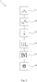
- Fig. 1 a first embodiment of a fill level measuring device 2 according to the invention, which is suitable for carrying out a method 1 according to the invention.
- the level measuring device 2 works on the radar principle. It comprises a mounting housing 3 with a leakage chamber 4 arranged on the process side, a signal conductor 5 for conducting transmission and / or reception signals, a transmission and reception unit 6a designed for transmitting and receiving the transmission and reception signals and a control and evaluation unit 6b designed for Controlling the transmitting and receiving unit 6a and for evaluating the received signals.
- the signal conductor 5 is routed from the interior of the leakage chamber 4 of the holder housing 3 through a process-side first opening 7 of the leakage chamber 4 and of the holder housing 3 into the process-side outer space of the holder housing 3.
- the process-side first opening 7 of the leakage chamber 4 and of the mounting housing 3 and the second opening 8 of the leakage chamber 4 facing the transmitting and receiving unit 6a are each sealed with a first seal 9 and with a second seal 10. This prevents the medium contained in the container (not shown) from being able to get into the environment. This is particularly relevant when the medium contained in the container is harmful to the environment or when high pressures prevail in the container.
- the control and evaluation unit 6b is designed in such a way that it is suitable for carrying out the method 1 according to the invention for monitoring a fill level measuring device 2.
- the leakage chamber 4 is filled with dry air. If the first seal 9 on the process side is leaky, medium penetrates from the container (not shown) into the leakage chamber 4. This state can be detected quickly and reliably by the method 1 according to the invention.
- a pulse-shaped electromagnetic signal in this case a radar signal, is transmitted along the signal conductor 5 in the direction of the medium to be measured.
- This pulse-shaped signal is transmitted to impedance jumps, such as the transition to the process-side, in Fig. 1 container, not shown, or the surface of the medium to be measured is reflected.
- the reflected received signal is received by the transmitting and receiving unit 6a and forwarded to the control and evaluation unit 6b for further evaluation 13.
- the frequency spectrum of the received signal is determined 14 by means of a Fourier transformation.
- This frequency spectrum which can be assigned to a received signal, is the basis for monitoring the level measuring device 2, in particular for detecting the tightness of the first, process-side seal 9.
- the presence of a leak is detected by a change in the measured frequency spectrum.
- a leak can thus be detected quickly and reliably in an advantageous manner.
- the illustrated embodiment of the method 1 determines the frequency spectrum of the range of the received signal, which is to be assigned to the leakage chamber based on its transit time. In this respect, irrelevant changes, such as changes in the fill level of the container for the evaluation of the detection of a leak, are disregarded.
- a monitoring parameter is determined from the frequency spectrum, the change of which correlates with a leak.
- the measured frequencies and the amplitudes of the signals in the frequency space are summarized in a matrix so that an image of a received signal is available.
- the singular values of the matrix that can be uniquely assigned to the matrix are determined from this matrix with the aid of the singular value decomposition 16. These singular values change as a function of the individual entries in the matrix and thus as a function of the change in the frequency spectrum.
- control and evaluation unit 6b has comparison matrices based on frequency spectra that were recorded or simulated with different media. By comparing the matrix created in step 15 with the comparison matrices, the medium penetrating into the leakage chamber 4 can be determined beyond the mere detection of a leak.
- the method according to the invention ensures, on the one hand, a quick and reliable detection of a leak in the seal to be monitored;
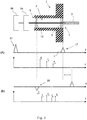
- Fig. 3 shows a second exemplary embodiment of a fill level measuring device 2 according to the invention and a method 1 according to the invention for monitoring the fill level measuring device 2 Fig. 3
- the exemplary embodiment shown of a fill level measuring device 2 according to the invention has a mounting housing 3 with a leakage chamber 4 arranged on the process side, a signal conductor 5 for conducting transmission and / or reception signals, a transmission and reception unit 6a designed for transmitting and receiving the transmission or reception signals and a control and evaluation unit 6b designed for controlling the transmission and receiving unit and for evaluating the received signals.
- the signal conductor 5 is routed from the interior of the leakage chamber 4 of the holder housing 3 through a process-side first opening 7 of the leakage chamber 4 and of the holder housing 3 into the process-side outer space of the holder housing 3.
- the process-side first opening 7 of the leakage chamber and of the mounting housing 3 and the second opening 8 of the leakage chamber facing the transmitting and receiving unit 6a are each sealed with a first seal 9 or with a second seal 10.
- the impedances of the interior of the leakage chamber 4, the seals 9 and 10 and the signal conductor 5 are equal.
- the control and evaluation unit 6b is designed in such a way that it is suitable for carrying out the method 1 according to the invention.
- the graphs shown below the level measuring device 2 show a second exemplary embodiment of a method 1 according to the invention.
- An exemplary embodiment of the defect-free state is shown under (A).
- the upper graph shows the emission 11 of a pulse-shaped signal and the reflection 17 of this signal at the impedance transition after the first seal 9 on the process side.
- the lower graph shows the discrete frequency spectrum determined from this reflection, which consists of the frequencies f1, f2 and f3.
- Fig. 4 shows a first measurement of the received signal both for the defect-free state and for the case that the seal between the container and the holder housing or the leakage chamber has a leak.
- the area of the received signal that is to be assigned to the leak chamber is mapped here.
- the measurement shows a first received signal 19 of the defect-free state. Due to the reflection of the signal when entering and exiting the leakage chamber, this first received signal 19 has two pulses.
- a second received signal 20 of a state is shown in which a first oil with a permittivity of 2.3 has partially penetrated the leakage chamber.
- the course of the second received signal 20 has a further pulse that is based on the reflection of the transmitted signal at the transition to the first oil.
- a third received signal 21 is shown, which is based on the condition that the first oil has almost completely penetrated the leakage chamber. The additional reflection therefore takes place earlier than the second received signal 20.
- a fourth received signal 22 shows the state that a second oil with a permittivity of 5.7 has partially penetrated the leakage chamber.
- the course of this received signal 22 also has a further pulse that is based on the reflection of the transmitted signal on the second oil.
- a further fifth received signal 23 shows the state that the second oil has almost completely penetrated the leakage chamber. In comparison to the course of the fourth received signal 22, the additional pulse occurs earlier in time.
- the measurement shown shows, as is also known from the prior art, that the penetration of a medium into the leakage chamber can be detected by the course of the received signal.
- the Figures 5 and 6 show the frequency decomposition of the in Fig. 4 received signals shown. Shows in detail Fig. 5 a first frequency spectrum 24 based on the first received signal 19 in the defect-free state. Besides shows Fig. 5 a second frequency spectrum 25, which is based on the received signal, in which the first oil has partially penetrated into the leakage chamber, and a third frequency spectrum 26 of the received signal in which the first oil has penetrated almost completely into the leakage chamber. The comparison shows that the frequency spectra differ both in the position of individual frequencies and in their amplitude.
- Fig. 6 shows a first frequency spectrum 24 based on the first received signal 19 in the defect-free state.
- a second frequency spectrum 27 which is based on the received signal, in which the second oil has partially penetrated into the leakage chamber and a third frequency spectrum 28 of the received signal in which the second oil has almost completely penetrated into the leakage chamber.
- the comparison also shows that the frequency spectra differ both in the position of individual frequencies and in their amplitude.
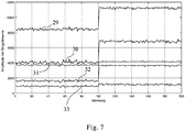
- Fig. 7 shows the suitability of the singular values of a matrix of measured values for the detection of a leak.
- the measurement shown initially shows the course of individual singular values 29 to 33 for the defect-free state. From a measured value of 100, the measurement shows a state in which the leak chamber has been filled with the second oil. In the example shown, this results in a change in each individual singular value.
- the measurement shows the fundamental suitability of the singular values of the matrix as monitoring parameters and, in particular, for the detection of a leak.
Description
Die Erfindung betrifft ein Verfahren zur Überwachung eines nach dem Radarprinzip arbeitenden Füllstandmessgeräts, wie es im angefügten unabhängigen Patentanspruch 1 spezifiziert ist.The invention relates to a method for monitoring a fill level measuring device operating according to the radar principle, as specified in the attached
Darüber hinaus betrifft die Erfindung ein nach dem Radarprinzip arbeitendes Füllstandmessgerät, wie es im angefügten unabhängigen Patentanspruch 10 spezifiziert ist.In addition, the invention relates to a fill level measuring device operating according to the radar principle, as specified in the attached
In der industriellen Messtechnik werden häufig Radarfüllstandmessgeräte eingesetzt, um den Füllstand von Medien wie beispielsweise Flüssigkeiten, Schüttgütern oder auch Schlämmen innerhalb von Behältern wie Tanks oder Silos zu bestimmen. Das durch die Messgeräte umgesetzte physikalische Prinzip ist das Laufzeitverfahren. Im Detail wird ein elektromagnetisches pulsförmiges Signal entlang des Signalleiters ausgesendet, welches an der Füllgutoberfläche reflektiert und anschließend von der Empfangseinheit registriert wird. Aus der Laufzeit des reflektierten Empfangssignals kann der Abstand zur Füllgutoberfläche und bei bekanntem Abstand zum Boden des Behälters der Füllstand des Behälters bestimmt werden. Bei den gesendeten und empfangenen Signalen handelt es sich zumeist um Mikrowellenstrahlung.In industrial metrology, radar level gauges are often used to determine the level of media such as liquids, bulk materials or even sludge within containers such as tanks or silos. The physical principle implemented by the measuring devices is the runtime method. In detail, an electromagnetic pulse-shaped signal is transmitted along the signal conductor, which is reflected on the surface of the product and is then registered by the receiving unit. The distance to the product surface and, if the distance to the bottom of the container is known, the fill level of the container can be determined from the transit time of the reflected received signal. The signals sent and received are mostly microwave radiation.
Häufig werden dielektrische Resonatoren als Signalleiter eingesetzt. Diese haben ein ähnliches Resonanzverhalten wie Hohlleiter, können aber, da sie nicht über metallische Wandungen verfügen, elektromagnetische Energie abstrahlen und damit als Antennen fungieren.Dielectric resonators are often used as signal conductors. These have a similar resonance behavior as waveguides, but because they do not have metallic walls, they can emit electromagnetic energy and thus function as antennas.
Messgeräte sind üblicherweise gegen das Füllgut, dessen Füllstand zu bestimmen ist, abgedichtet. Zusätzlich kann eine Leckkammer, die sowohl prozessseitig als auch auf der dem Füllgut abgewandten Seite abgedichtet ist, vorgesehen sein. Insbesondere bei aggressivem, umweltschädlichen oder explosionsgefährlichen Füllgut oder wenn in den Prozessen hohe Drücke und Temperaturen vorliegen, ist eine solche Leckkammer vorteilhaft, um den Zustand der prozessseitigen Dichtung zu überwachen.Measuring devices are usually sealed against the product, the level of which is to be determined. In addition, a leakage chamber, which is sealed both on the process side and on the side facing away from the filling material, can be provided. Such a leakage chamber is advantageous in order to monitor the condition of the process-side seal, particularly in the case of aggressive, environmentally harmful or explosive filling material or if high pressures and temperatures are present in the processes.
Die Erfindung betrifft insbesondere ein Verfahren zur Überwachung der Dichtigkeit einer zwischen dem Behälter und dem Halterungsgehäuse und/oder der Leckkammer angeordneten Dichtung.The invention relates in particular to a method for monitoring the tightness of a seal arranged between the container and the mounting housing and / or the leakage chamber.
Die Druckschrift
Aus der Druckschrift
Ein Verfahren zur Detektion einer Leckage in der Dichtung zwischen dem Messgerät und dem Medium enthaltenen Behälter basierend auf der Zeitbereichsreflektometrie ist ebenfalls aus der
Gemäß dem dargelegten Stand der Technik erfolgt der Nachweis einer Leckage ausschließlich im Zeitraum. Eine weitere Auswertung, insbesondere ein Quantifizierung der Veränderung im Empfangssignal, welche weiteren Aufschluss über das eindringende Medium geben könnte, findet jedoch nicht statt.According to the state of the art presented, a leak is only detected in the period of time. However, there is no further evaluation, in particular a quantification of the change in the received signal, which could provide further information about the penetrating medium.
Ausgehend von diesem Stand der Technik ist es Aufgabe der vorliegenden Erfindung, ein Verfahren zur Überwachung eines nach dem Radarprinzip arbeitenden Füllstandmessgerätes sowie ein entsprechendes Füllstandmessgerät anzugeben, mit welchem neben dem einfachen Nachweis des Vorhandenseins einer Leckage ebenfalls die Änderung im Empfangssignal quantifiziert werden kann.Based on this prior art, the object of the present invention is to provide a method for monitoring a level measuring device operating on the radar principle and a corresponding level measuring device with which the change in the received signal can also be quantified in addition to the simple detection of the presence of a leak.
In den folgenden Ausführungen wird zur Erläuterung des erfindungsgemäßen Verfahrens auf zwei verschiedene Zustände des Füllstandmessgeräts Bezug genommen. Dabei wird mit "defektfrei" der Zustand bezeichnet, in dem alle Dichtungen im Übergangsbereich zwischen dem Behälter und dem Halterungsgehäuse bzw. der Leckkammer in Ordnung sind und kein Medium aus dem Behälter in die Leckkammer eindringen kann. Davon zu unterscheiden ist der Zustand "defekt" im Fall einer Leckage. Damit wird der Zustand bezeichnet, in dem die Dichtung zwischen dem Behälter und dem Halterungsgehäuse bzw. der Leckkammer defekt ist, sodass aus dem Behälter zumindest ein Teil des Mediums in die Leckkammer eindringen kann.In the following explanations, reference is made to two different states of the fill level measuring device to explain the method according to the invention. "Defect-free" refers to the state in which all the seals in the transition area between the container and the mounting housing or the leakage chamber are in order and no medium can penetrate from the container into the leakage chamber. This is to be distinguished from the "defective" state in the event of a leak. This denotes the state in which the seal between the container and the holder housing or the leakage chamber is defective, so that at least part of the medium can penetrate from the container into the leakage chamber.
Die oben genannte Aufgabe wird gemäß einer ersten Lehre der vorliegenden Erfindung bei einem eingangs dargelegten Verfahren dadurch gelöst, dass das Frequenzspektrum des Empfangssignals bestimmt wird und die Überwachung im Frequenzraum erfolgt.According to a first teaching of the present invention, the above-mentioned object is achieved in a method set out in the introduction in that the frequency spectrum of the received signal is determined and the monitoring takes place in the frequency domain.
Erfindungsgemäß wurde erkannt, dass das Eindringen eines Mediums in die Leckkammer nicht nur eine zusätzliche Reflexion im Empfangssignal bewirkt, sondern sich ebenfalls auf das im Empfangssignal enthaltene Frequenzspektrum auswirkt. Im Detail findet zumindest teilweise eine Frequenzverschiebung der Frequenzen, die im Empfangssignal im defektfreien Zustand enthalten sind, statt. Darüber hinaus enthält das Empfangssignal im Fall einer vorhandenen Leckage, also im Zustand "defekt", weitere Frequenzen und unterscheidet sich dadurch ebenfalls von dem Spektrum im defektfreien Zustand. Dabei hat der Nachweis einer Leckage durch die Änderung im Frequenzspektrum des Empfangssignals den Vorteil, dass Änderungen im Empfangssignal anhand von konkreten Parametern, wie beispielsweise der Größe der Frequenz und/oder der Amplitude der Signale im Frequenzraum, beschrieben werden können, sodass eine Änderung des Empfangssignals nicht nur besonders einfach festgestellt, sondern ebenso einfach auch quantifiziert werden kann.According to the invention, it was recognized that the penetration of a medium into the leakage chamber not only causes an additional reflection in the received signal, but also affects the frequency spectrum contained in the received signal. In detail, there is at least a partial frequency shift of the frequencies that are contained in the received signal in the defect-free state. In addition, in the event of a leak, that is to say in the "defective" state, the received signal contains further frequencies and thus also differs from the spectrum in the defect-free state. Detecting a leak through the change in the frequency spectrum of the received signal has the advantage that changes in the received signal can be described using specific parameters, such as the size of the frequency and / or the amplitude of the signals in the frequency domain, so that a change in the received signal Not only can it be determined particularly easily, but also quantified just as easily.
Dabei können in die Leckkammer eindringende Medien mit verschiedenen Permittivitäten aufgrund ihrer unterschiedlich starken Abschwächung des Sende- bzw. Empfangssignals anhand der Amplituden der Signale im Frequenzspektrum voneinander unterschieden werden. Insofern findet durch das erfindungsgemäße Verfahren nicht nur der reine Nachweis einer Leckage statt, vielmehr kann auch eine Aussage über die Art und/oder die Eigenschaften des eindringenden Mediums getroffen werden.In this case, media with different permittivities penetrating into the leakage chamber can be distinguished from one another based on the amplitudes of the signals in the frequency spectrum due to their differently strong attenuation of the transmitted or received signal. In this respect, the method according to the invention not only provides pure detection of a leak, but rather a statement can also be made about the type and / or properties of the penetrating medium.
Gemäß einer ersten vorteilhaften Ausgestaltung wird das Frequenzspektrum des Bereichs des Empfangssignals bestimmt, der aufgrund seiner Laufzeit der Leckkammer zuzuordnen ist. Gemäß dieser Ausgestaltung wird genau der Bereich des Empfangssignals ausgewertet, in dem eine Änderung aufgrund einer Leckage zu erwarten ist. Zum einen kann dadurch ausgeschlossen werden, dass Änderungen im beobachteten Frequenzspektrum auf der Änderung des Füllstandes im Behälter beruhen. Zum anderen sind Änderungen im Frequenzspektrum besonders deutlich und einfach nachzuweisen, da der zu untersuchende Bereich des Empfangssignals keine Frequenzanteile enthält, die auf für das vorliegende Verfahren nicht relevanten Reflexionen basieren. Das Hintergrundssignal kann somit auf ein Minimum reduziert werden. Für das erfindungsgemäße Verfahren nicht relevante Reflexionen sind beispielsweise die Reflexion des Sendesignals an der Füllgutoberfläche oder die Reflexion an dem Boden des Behälters.According to a first advantageous embodiment, the frequency spectrum of the range of the received signal is determined which is to be assigned to the leakage chamber on the basis of its transit time. According to this embodiment, precisely that area of the received signal in which a change is to be expected due to a leak is evaluated. On the one hand, it can be ruled out that changes in the observed frequency spectrum are based on the change in the filling level in the container. On the other hand, there are changes It is particularly clear and easy to detect in the frequency spectrum, since the area of the received signal to be examined does not contain any frequency components that are based on reflections that are not relevant for the present method. The background signal can thus be reduced to a minimum. Reflections that are not relevant for the method according to the invention are, for example, the reflection of the transmission signal on the surface of the product or the reflection on the bottom of the container.
Gemäß der Erfindung wird aus dem Frequenzspektrum des Empfangssignals wenigstens ein Überwachungsparameter zur Überwachung des Füllstandmessgeräts extrahiert. Dabei erfolgt, insbesondere während einer laufenden Messung, der Nachweis einer Leckage durch Änderung eines Überwachungsparameters. Gemäß dieser Ausgestaltung kann der Nachweis einer Leckage besonders schnell und zuverlässig erfolgen.According to the invention, at least one monitoring parameter for monitoring the level measuring device is extracted from the frequency spectrum of the received signal. A leak is detected by changing a monitoring parameter, in particular while a measurement is in progress. According to this embodiment, a leak can be detected particularly quickly and reliably.
Überwachungsparameter sind vorzugsweise der Wert einzelner Frequenzen und/oder die Amplitude der Signale im Frequenzraum und/oder weitere Parameter, die mittelbar aus dem Frequenzspektrum abgeleitet werden und die sich bei Eindringen eines Mediums in die Leckkammer ändern.Monitoring parameters are preferably the value of individual frequencies and / or the amplitude of the signals in the frequency space and / or other parameters that are derived indirectly from the frequency spectrum and that change when a medium penetrates the leakage chamber.
Ein solcher Parameter ist beispielsweise die Resonanzfrequenz des durch die Leckkammer gebildeten Resonators. Dringt in die Leckkammer, die beispielsweise mit trockener Luft gefüllt ist, ein von Luft verschiedenes Medium ein, so ändert sich die Ausbreitungsgeschwindigkeit des Sendesignals, das sich entlang des Signalleiters fortbewegt. In der Folge ändert sich die Resonanzfrequenz des durch die Leckkammer gebildeten Resonators. Diese kann bei Kenntnis der Resonatorlänge aus dem gemessenen Frequenzspektrum bestimmt werden. Insofern ist eine Änderung der Resonanzfrequenz ein Indikator für eine Leckage der interessierenden Dichtung.Such a parameter is, for example, the resonance frequency of the resonator formed by the leakage chamber. If a medium other than air penetrates into the leakage chamber, which is filled, for example, with dry air, the speed of propagation of the transmitted signal, which moves along the signal conductor, changes. As a result, the resonance frequency of the resonator formed by the leakage chamber changes. If the resonator length is known, this can be determined from the measured frequency spectrum. In this respect, a change in the resonance frequency is an indicator of a leak in the seal of interest.
Alternativ oder zusätzlich kann ein Überwachungsparameter dadurch bestimmt werden, dass eine Vielzahl von Messwerten, deren Größe von dem Medium in der Leckkammer abhängig ist, zusammengefasst wird und dass wenigstens ein Parameter bestimmt wird, der sich in Abhängigkeit eines oder mehrerer dieser Messwerte ändert.Alternatively or additionally, a monitoring parameter can be determined by combining a large number of measured values, the size of which depends on the medium in the leakage chamber, and that at least one parameter is determined which changes as a function of one or more of these measured values.
Besonders bevorzugt werden die gemessenen Frequenzen und/oder die Amplituden der Signale im Frequenzraum in einer Matrix zusammengefasst und es wird ein Parameter bestimmt, der sich in Abhängigkeit der einzelnen Einträge der Matrix ändert. Diese Ausgestaltung weist den Vorteil auf, dass gleichzeitig eine Vielzahl von einzelnen Frequenzen und/oder Amplituden überwacht werden kann, wobei eine Änderung von einzelnen Frequenzen und/oder Amplituden als Nachweis einer Leckage registriert wird.The measured frequencies and / or the amplitudes of the signals in the frequency space are particularly preferably combined in a matrix and a parameter is determined which changes depending on the individual entries in the matrix. This embodiment has the advantage that a large number of individual frequencies and / or amplitudes can be monitored at the same time, a change in individual frequencies and / or amplitudes being registered as evidence of a leak.
Beispielsweise kann im Fall einer quadratischen Matrix ein solcher Parameter die Determinante der Matrix sein. Diese ist allein abhängig von den einzelnen Elementen der Matrix und ändert sich, sofern sich ein Eintrag der Matrix ändert. Alternativ oder zusätzlich kann für beliebige Dimensionen der Matrix ein Parameter zur Überwachung des Zustandes des Füllstandmessgeräts ein oder mehrere Singulärwerte der Matrix sein. Diese sind ebenfalls durch die Einträge der Matrix eindeutig bestimmt. Eine Änderung einzelner Einträge resultiert in einer zumindest teilweise Änderung der Singulärwerte, sodass diese Parameter ebenfalls als Überwachungsparameter für den Zustand des Füllstandmessgeräts geeignet sind. Durch diese Ausgestaltung des erfindungsgemäßen Verfahrens lassen sich insbesondere auch in die Lecckammer eindringende Medien mit nur geringfügig unterschiedlicher Permittivität unterscheiden. Insofern ist dieses Verfahren hochempfindlich und daher besonders für den Nachweis einer Leckage geeignet.For example, in the case of a square matrix, such a parameter can be the determinant of the matrix. This is solely dependent on the individual elements of the matrix and changes if an entry in the matrix changes. Alternatively or additionally, a parameter for monitoring the state of the fill level measuring device can be one or more singular values of the matrix for any dimensions of the matrix. These are also clearly defined by the entries in the matrix. A change in individual entries results in an at least partial change in the singular values, so that these parameters are also suitable as monitoring parameters for the state of the level measuring device. This embodiment of the method according to the invention also makes it possible to distinguish, in particular, media penetrating the leak chamber with only slightly different permittivities. In this respect, this method is highly sensitive and therefore particularly suitable for detecting a leak.
Um den Rechenaufwand gering zu halten, wird die Größe bzw. die Dimension der aus den Messwerten gebildeten Matrix derart angepasst, dass eine angemessene Auflösung gewährleistet werden kann.In order to keep the computational effort low, the size or the dimension of the matrix formed from the measured values is adapted in such a way that an appropriate resolution can be guaranteed.
Zur Extraktion eines Überwachungsparameters aus einer Matrix kann beispielsweise der Matrix Pencil Algorithmus angewendet werden.For example, the matrix pencil algorithm can be used to extract a monitoring parameter from a matrix.
Gemäß einer weiteren vorteilhaften Ausgestaltung erfolgt die Bestimmung des Frequenzspektrum durch eine Fouriertransformation des Empfangssignals. Mit Hilfe der Fouriertransformation lassen sich zeitlich kontinuierliche, nicht periodische Signale im Frequenzraum durch eine Zerlegung in einzelnen Frequenzanteilen darstellen. Insofern ist es möglich, einem reflektierten Empfangssignal eine eindeutige Vielzahl an Frequenzen und/oder Amplituden der Signale im Frequenzraum zuzuordnen. Auf diese Weise ist eine Änderung des Empfangssignals besonders einfach nachzuweisen und zu quantifizieren.According to a further advantageous embodiment, the frequency spectrum is determined by means of a Fourier transformation of the received signal. With the help of the Fourier transformation, time-continuous, non-periodic signals in the frequency space can be represented by breaking them down into individual frequency components. In this respect, it is possible to assign an unambiguous number of frequencies and / or amplitudes of the signals in the frequency space to a reflected received signal. In this way, a change in the received signal is particularly easy to detect and quantify.
Besonders bevorzugt ist es ebenfalls, wenn die Auswerteeinheit eine Vielzahl von hinterlegten Matrizen für verschiedene Medien mit unterschiedlichen Permittivitäten aufweist und wenn die aus den gemessenen Frequenzen und/oder Amplituden erzeugte Matrix mit den hinterlegten Matrizen verglichen wird. Dies hat den Vorteil, dass aus dem gemessenen Empfangssignal auf die Art und/oder die Eigenschaften des Mediums in der Leckkammer geschlossen werden kann.It is also particularly preferred if the evaluation unit has a plurality of stored matrices for different media with different permittivities and if the matrix generated from the measured frequencies and / or amplitudes is compared with the stored matrices. This has the advantage that the type and / or properties of the medium in the leakage chamber can be deduced from the measured received signal.
Dabei ist es besonders vorteilhaft, wenn die Pulslänge des Sendesignals bei der Bestimmung bzw. Aufnahme von Vergleichsmatrizen und/oder bei einer laufenden Messung variiert wird, sodass der Komplexitätsgrad der jeweiligen Matrix angepasst werden kann.It is particularly advantageous if the pulse length of the transmission signal is varied when determining or recording comparison matrices and / or when a measurement is in progress, so that the degree of complexity of the respective matrix can be adapted.
Um den Rechenaufwand zu minimieren, wird vorzugsweise nur im Fall einer Leckage die Matrix zur Bestimmung des in die Leckkammer eintretenden Mediums mit den in der Auswerteeinheit hinterlegten Vergleichsmatrizen verglichen.In order to minimize the computational effort, the matrix for determining the medium entering the leakage chamber is preferably compared with the comparison matrices stored in the evaluation unit only in the event of a leak.
Gemäß einer zweiten Lehre der vorliegenden Erfindung wird die eingangs dargelegte Aufgabe durch das eingangs genannte nach dem Radarprinzip arbeitende Füllstandmessgerät dadurch gelöst, dass dieses eine Auswerteeinheit aufweist, die derart ausgestaltet ist, dass das Frequenzspektrum des Empfangssignals bestimmt wird und dass die Überwachung des Füllstandmessgeräts im Frequenzraum erfolgt.According to a second teaching of the present invention, the object set out at the beginning is achieved by the fill level measuring device mentioned at the beginning, which operates on the radar principle, in that it has an evaluation unit which is designed such that the frequency spectrum of the received signal is determined and that the monitoring of the fill level measuring device in the frequency domain he follows.
Vorzugsweise ist die Auswerteeinheit zur Durchführung eines der zuvor beschriebenen Verfahren ausgestaltet.The evaluation unit is preferably designed to carry out one of the methods described above.
Im Einzelnen gibt es nun eine Vielzahl von Möglichkeiten, das erfindungsgemäße Verfahren zur Überwachung eines nach dem Radarprinzip arbeitenden Füllstandmessgerät und das erfindungsgemäße Füllstandmessgerät auszugestalten. Dazu wird verwiesen sowohl auf die den unabhängigen Patentansprüchen nachgeordneten Patentansprüche als auch auf die nachfolgende Beschreibung von bevorzugten Ausführungsbeispielen in Verbindung mit der Zeichnung. In der Zeichnung zeigen
- Fig.1
- ein erstes Ausführungsbeispiel einer erfindungsgemäßen Vorrichtung,
- Fig. 2
- ein erstes Ausführungsbeispiels eines erfindungsgemäßen Verfahrens,
- Fig. 3
- ein zweites Ausführungsbeispiel einer erfindungsgemäßen Vorrichtung und eines erfindungsgemäßen Verfahrens,
- Fig. 4
- eine erste Messung des Empfangssignals sowohl für den defektfreien Zustand als auch für den Fall einer Leckage, wobei zwei verschiedene Medien in die Leckkammer eindringen,
- Fig. 5
- die Darstellung des defektfreien Zustandes im Vergleich zu dem Eindringen des ersten Mediums im Frequenzraum,
- Fig. 6
- die Darstellung des defektfreien Zustandes im Vergleich zu dem Eindringen des zweiten Mediums im Frequenzraum und
- Fig. 7
- eine zweite Messung der Singulärwerte einer Matrix aus gemessenen Frequenzen.
- Fig. 1
- a first embodiment of a device according to the invention,
- Fig. 2
- a first embodiment of a method according to the invention,
- Fig. 3
- a second embodiment of a device according to the invention and a method according to the invention,
- Fig. 4
- a first measurement of the received signal both for the defect-free state and in the event of a leak, whereby two different media penetrate into the leakage chamber,
- Fig. 5
- the representation of the defect-free state in comparison to the penetration of the first medium in the frequency domain,
- Fig. 6
- the representation of the defect-free state in comparison to the penetration of the second medium in the frequency domain and
- Fig. 7
- a second measurement of the singular values of a matrix of measured frequencies.
In
Durch das Vorhandensein der Leckkammer 4 kann die Dichtigkeit der prozessseitigen ersten Dichtung 9 durch das erfindungsgemäße Verfahren 1 überprüft werden. Dazu ist im dargestellten Ausführungsbeispiel die Steuer-und Auswerteeinheit 6b derart ausgestaltet, dass sie zu Durchführung des erfindungsgemäßen Verfahrens 1 zur Überwachung eines Füllstandmessgeräts 2 geeignet ist. Im dargestellten Ausführungsbeispiel ist die Leckkammer 4 mit trockener Luft gefüllt. Ist die erste, prozessseitige Dichtung 9 undicht, so dringt Medium aus dem nicht dargestellten Behälter in die Leckkammer 4. Dieser Zustand kann durch das erfindungsgemäße Verfahren 1 schnell und zuverlässig nachgewiesen werden.Due to the presence of the
In
Dieses einem Empfangssignal zuordenbare Frequenzspektrum ist Grundlage für die Überwachung des Füllstandmessgeräts 2 insbesondere für den Nachweis der Dichtigkeit der ersten, prozessseitigen Dichtung 9. Dabei wird das Vorhandensein einer Leckage durch eine Änderung im gemessenen Frequenzspektrum detektiert. Durch das erfindungsgemäße Verfahren 1 kann damit in vorteilhafter Weise sowohl eine Leckage schnell und zuverlässig detektiert werden. Darüber hinaus ist es auch möglich, aufgrund des Nachweises einer Änderung im Frequenzspektrum diese Änderung anhand konkreter Parameter zu quantifizieren und damit weitere Aussagen über das in die Leckkammer 4 eingedrungene Medium zu machen.This frequency spectrum, which can be assigned to a received signal, is the basis for monitoring the
Zur Verbesserung der Detektion von Änderungen im Frequenzspektrum wird im dargestellten Ausführungsbeispiel des erfindungsgemäßen Verfahrens 1 das Frequenzspektrum des Bereichs des Empfangssignals bestimmt, der aufgrund seiner Laufzeit der Leckkammer zuzuordnen ist. Insofern werden nicht relevante Änderungen, wie beispielsweise Änderungen im Füllstand des Behälters für die Auswertung des Nachweises einer Leckage außer Acht gelassen.To improve the detection of changes in the frequency spectrum, in the illustrated embodiment of the
Um eine besonders einfache und schnelle Detektion einer Leckage bereitzustellen, wird in einem nächsten Schritt 15 aus dem Frequenzspektrum ein Überwachungsparameter bestimmt, dessen Änderung mit einer Leckage korreliert.In order to provide a particularly simple and quick detection of a leak, in a next step 15 a monitoring parameter is determined from the frequency spectrum, the change of which correlates with a leak.
Vorliegend werden dazu die gemessenen Frequenzen und die Amplituden der Signale im Frequenzraum in einer Matrix zusammengefasst, sodass eine Abbildung eines Empfangssignals vorliegt. Aus dieser Matrix werden mit Hilfe der Singulärwertzerlegung 16 die der Matrix eindeutig zuordenbare Singulärwerte der Matrix bestimmt. Diese Singulärwerte ändern sich in Abhängigkeit der einzelnen Einträge der Matrix und insofern in Abhängigkeit der Änderung des Frequenzspektrums. Durch die fortlaufende Bestimmung eines oder mehrerer Singulärwerte der gemessenen Frequenzspektren lässt sich die Dichtigkeit der ersten, prozessseitigen Dichtung 9 kontinuierlich überwachen.In the present case, the measured frequencies and the amplitudes of the signals in the frequency space are summarized in a matrix so that an image of a received signal is available. The singular values of the matrix that can be uniquely assigned to the matrix are determined from this matrix with the aid of the
Zudem weist im dargestellten Verfahren die Steuer- und Auswerteeinheit 6b Vergleichsmatrizen basierend auf Frequenzspektren auf, die mit unterschiedlichen Medien aufgenommen oder simuliert wurden. Durch einen Vergleich der in Schritt 15 erstellten Matrix mit den Vergleichsmatrizen kann über den reinen Nachweis einer Leckage hinaus, das in die Leckkammer 4 eindringende Medium bestimmt werden.In addition, in the method shown, the control and
Insofern gewährleistet das erfindungsgemäße Verfahren zum einen einen schnellen und zuverlässigen Nachweis einer Leckage in der zu überwachenden Dichtung, zum anderen kann darüber hinaus durch einen Vergleich mit bereits hinterlegten Matrizen das in die Leckkammer eindringende Medium bestimmt werden.In this respect, the method according to the invention ensures, on the one hand, a quick and reliable detection of a leak in the seal to be monitored;
Im dargestellten Ausführungsbeispiel sind die Impedanzen des Innenraums der Leckkammer 4, der Dichtungen 9, und 10 und des Signalleiters 5 gleich groß.In the illustrated embodiment, the impedances of the interior of the
Die Steuer- und Auswerteeinheit 6b ist derart ausgestaltet, dass sie zur Durchführung des erfindungsgemäßen Verfahrens 1 geeignet ist.The control and
Die unterhalb des Füllstandmessgeräts 2 dargestellten Graphen zeigen ein zweites Ausführungsbeispiel eines erfindungsgemäßen Verfahrens 1. Unter (A) ist ein Ausführungsbeispiel des defektfreien Zustandes dargestellt. Der obere Graph zeigt die Aussendung 11 eines pulsförmigen Signals sowie die Reflexion 17 dieses Signals an dem Impedanzübergang nach der prozessseitigen, ersten Dichtung 9. Der untere Graph zeigt das aus dieser Reflexion bestimmte diskrete Frequenzspektrum, welches aus den Frequenzen f1, f2 und f3 besteht.The graphs shown below the
Unter (B) ist im Vergleich zu (A) die Situation einer Leckage der ersten Dichtung 9 dargestellt. Aufgrund des in die Leckkammer 4 eingedrungenen Mediums findet bereits aufgrund des Impedanzüberganges nach der zweiten Dichtung 10 eine Reflexion 18 des ausgesendeten pulsförmigen Signals statt. Zudem erfolgt die zweite Reflexion 17, welche am Impedanzübergang nach der ersten Dichtung 9 stattfindet aufgrund der niedrigeren Ausbreitungsgeschwindigkeit des Sendesignals im Medium, das in die Leckkammer 4 eingedrungen ist, zeitlich verzögert. Der untere Graph zeigt das zu dem Empfangssignal zuordenbare Frequenzspektrum. Im Vergleich zu dem unter (A) dargestellten Frequenzspektrum des defektfreien Zustandes findet eine Frequenzverschiebung der Frequenzen f1 bis f3 statt, wobei ebenfalls Unterschiede in den Amplituden der Frequenzen im Frequenzraum bestehen. Darüber hinaus weist das Frequenzspektrum unter (B) zusätzliche Frequenzen f4 und f5 auf.In comparison to (A), the situation of a leak in the
Die dargestellte Messung zeigt, wie auch aus dem Stand der Technik bekannt, dass sich das Eindringen eines Mediums in die Leckkammer durch den Verlauf des Empfangssignal nachweisen lässt.The measurement shown shows, as is also known from the prior art, that the penetration of a medium into the leakage chamber can be detected by the course of the received signal.
Die
- 1.1.
- Verfahren zur Überwachung eines nach dem Radarprinzip arbeitenden FüllstandmessgerätsMethod for monitoring a level measuring device that works according to the radar principle
- 2.2.
- FüllstandmessgerätLevel meter
- 3.3.
- HalterungsgehäuseBracket housing
- 4.4th
- LeckkammerLeakage chamber
- 5.5.
- SignalleiterSignal conductor
- 6a.6a.
- Sende- und EmpfangseinheitTransmitter and receiver unit
- 6b.6b.
- Steuer- und AuswerteeinheitControl and evaluation unit
- 7.7th
- erste Öffnungfirst opening
- 8.8th.
- zweite Öffnungsecond opening
- 9.9.
- erste Dichtungfirst seal
- 10.10.
- zweite Dichtungsecond seal
- 11.11.
- Aussenden eines pulsförmigen SendesignalsSending a pulse-shaped transmission signal
- 12.12th
- Empfangen eines reflektierten EmpfangssignalsReceiving a reflected received signal
- 13.13th
- Weiterleiten des Empfangssignals an die Steuer- und AuswerteeinheitForwarding of the received signal to the control and evaluation unit
- 14.14th
- Bestimmung des Frequenzspektrums des EmpfangssignalsDetermination of the frequency spectrum of the received signal
- 15.15th
- Bestimmung eines ÜberwachungsparametersDetermination of a monitoring parameter
- 16.16.
- SingulärwertzerlegungSingular value decomposition
- 17.17th
- Reflexionreflection
- 18.18th
- Reflexionreflection
- 19.19th
- Empfangssignal des defektfreien ZustandesReceived signal of the defect-free state
- 20.20th
- Empfangssignal wenn die Leckkammer teilweise mit einem ersten Öl gefüllt istReceived signal when the leakage chamber is partially filled with a first oil
- 21.21.
- Empfangssignal wenn die Leckkammer fast vollständig mit einem ersten Öl gefüllt istReceived signal when the leakage chamber is almost completely filled with a first oil
- 22.22nd
- Empfangssignal wenn die Leckkammer teilweise mit einem zweiten Öl gefüllt istReceived signal when the leakage chamber is partially filled with a second oil
- 23.23
- Empfangssignal wenn die Leckkammer fast vollständig mit einem zweiten Öl gefüllt istReceived signal when the leakage chamber is almost completely filled with a second oil
- 24.24.
- Frequenzspektrum des defektfreien ZustandesFrequency spectrum of the defect-free state
- 25.25th
-
Frequenzspektrum des Empfangssignals 21Frequency spectrum of the received
signal 21 - 26.26th
-
Frequenzspektrum des Empfangssignals 22Frequency spectrum of the received
signal 22 - 27.27
-
Frequenzspektrum des Empfangssignals 23Frequency spectrum of the received
signal 23 - 28.28.
-
Frequenzspektrum des Empfangssignals 24Frequency spectrum of the received
signal 24 - 29.29
- SingulärwertSingular value
- 30.30th
- SingulärwertSingular value
- 31.31.
- SingulärwertSingular value
- 32.32.
- SingulärwertSingular value
- 33.33.
- SingulärwertSingular value
Claims (11)
- Method (1) for monitoring a level meter (2) operating according to the radar principle, wherein the level meter (2) has a bracket housing (3) with a leakage chamber (4) arranged on the process side, a signal conductor (5) for conducting transmitted and/or received signals, a transmitting and receiving unit (6a) designed for transmitting and receiving the transmitted or, respectively, received signals, and a control and evaluation unit (6b) designed for controlling the transmitting and receiving unit and for evaluating the received signals, wherein the signal conductor (5) is lead out of the inner space of the leakage chamber (4) of the bracket housing (3) through a process-side first opening (7) of the leakage chamber (4) and/or of the bracket housing (3) into the process-side outer space of the bracket housing (3), wherein the process-side first opening (7) of the leakage chamber (4) and/or of the bracket housing (3) and a second opening (8) of the leakage chamber (4) and/or bracket housing (3) facing the transmitting and receiving unit (6a) are each sealed with a first seal (9) or with a second seal (10), comprising the following method steps:- transmitting (11) a transmitted signal in the form of a pulse along the signal conductor (5),- receiving (12) a reflected received signal,- relaying (13) the received signal to the control and evaluation unit (6b) characterized in,that the frequency spectrum of the received signal is determined and that the monitoring of the level meter (2) is carried out in the frequency domain, wherein at least one monitoring parameter for monitoring the level meter (2) is extracted from the frequency spectrum of the received signal, and that a leakage is detected as a change in the monitoring parameter, wherein the entering of a medium into the leakage chamber affects the frequency spectrum contained in the received signal.
- Method (1) according to claim 1, characterized in that the frequency spectrum of the range of the received signal is determined, which is to be assigned to the leakage chamber (4) due to its transit time.
- Method (1) according to claim 1 or 2, characterized in that the monitoring parameter is the value of individual frequencies and/or the amplitudes of the signals in the frequency domain and/or further parameters that are indirectly derived from the frequency spectrum.
- Method (1) according to any one of claims 1 to 3, characterized in that additional or alternative monitoring parameters are the resonance frequencies of the signal conductor (5).
- Method (1) according to any one of claims 1 to 4, characterized in that additionally or alternatively, the monitoring parameters are characterized in that the individual frequencies and/or amplitudes of a frequency spectrum are combined and that at least one parameter is determined that changes in dependence on the change of one or several of these frequencies and/or amplitudes.
- Method (1) according to any one of claims 1 to 5, characterized in that the measured frequencies and/or the amplitudes of the signals in the frequency domain are combined in a matrix and that one or several singular values of the matrix is/are monitoring parameter(s).
- Method (1) according to any one of claims 1 to 6, characterized in that the frequency spectrum is determined using a Fourier transformation of the received signal.
- Method (1) according to any one of claims 1 to 7, characterized in that the control and evaluation unit (6b) has a plurality of stored, measured and/or simulated reference matrices for different media and that the matrix generated from the measured frequencies and/or amplitudes is compared to the stored matrices.
- Method (1) according to claim 8, characterized in that the matrix for determining the medium entering the leakage chamber (4) is only compared to the reference matrices stored in the evaluation unit (6b) in the case of a leakage.
- Level meter (2) operating according to the radar principle having a bracket housing (3) with a leakage chamber (4) arranged on the process side, a signal conductor (5) for conducting transmitted and/or received signals, a transmitting and receiving unit (6a) designed for transmitting and receiving of transmitted or received signals and a control and evaluation unit (6b) designed for controlling the transmitting and receiving unit (6a) and for evaluating the received signal, wherein the signal conductor (5) is lead out of the inner space of the leakage chamber (4) of the bracket housing (3) through a process-side first opening (7) of the leakage chamber (4) and/or of the bracket housing (3) into the process-side outer space of the bracket housing (3), wherein the process-side first opening (7) of the leakage chamber (4) and/or of the bracket housing (3) and a second opening (8) of the leakage chamber (4) and/or bracket housing (3) facing the transmitting and receiving unit (6a) are each sealed with a first seal (9) or with a second seal (10),
characterized in
that the evaluation unit (6b) is designed for determining the frequency spectrum of the received signal for monitoring the level meter (2) in the frequency range, wherein at least one monitoring parameter for monitoring the level meter (2) is extracted from the frequency spectrum of the received signal, and wherein a leakage is detected as a change in the monitoring parameter, wherein the entering of a medium into the leakage chamber affects the frequency spectrum contained in the received signal. - Level meter (2) according to claim 10, characterized in that the evaluation unit (6b) is designed for carrying out a method according to any one of claims 1 to 9.
Applications Claiming Priority (1)
| Application Number | Priority Date | Filing Date | Title |
|---|---|---|---|
| DE102016108665.7A DE102016108665B4 (en) | 2016-05-11 | 2016-05-11 | Method for monitoring a level measuring device and level measuring device operating on the radar principle |
Publications (2)
| Publication Number | Publication Date |
|---|---|
| EP3244176A1 EP3244176A1 (en) | 2017-11-15 |
| EP3244176B1 true EP3244176B1 (en) | 2021-07-21 |
Family
ID=58488897
Family Applications (1)
| Application Number | Title | Priority Date | Filing Date |
|---|---|---|---|
| EP17164546.8A Active EP3244176B1 (en) | 2016-05-11 | 2017-04-03 | Method for monitoring a fill level measuring device operating according to the radar principle and fill level measuring device |
Country Status (4)
| Country | Link |
|---|---|
| US (1) | US10718655B2 (en) |
| EP (1) | EP3244176B1 (en) |
| CN (1) | CN107389152B (en) |
| DE (1) | DE102016108665B4 (en) |
Families Citing this family (1)
| Publication number | Priority date | Publication date | Assignee | Title |
|---|---|---|---|---|
| CN108955818A (en) * | 2018-08-10 | 2018-12-07 | 合肥市恒昌自动化控制有限责任公司 | Radar levelmeter with leakage detection function |
Family Cites Families (16)
| Publication number | Priority date | Publication date | Assignee | Title |
|---|---|---|---|---|
| GB1054455A (en) * | 1964-02-25 | |||
| US5996406A (en) * | 1997-05-20 | 1999-12-07 | Motorola, Inc. | Advanced signal process for a material storage measuring device |
| DE29822507U1 (en) * | 1998-12-17 | 1999-02-25 | Grieshaber Vega Kg | Level measuring device |
| US6775533B2 (en) | 2001-07-27 | 2004-08-10 | Nokia Corporation | Apparatus, and associated method, for transferring data between a first target entity and a second target entity of a mobile radio communication system |
| US20030222654A1 (en) * | 2001-11-30 | 2003-12-04 | Furse Cynthia M. | Cable testing, cable length, and liquid level determination system utilizing a standing wave reflectometer |
| US7255002B2 (en) * | 2005-04-07 | 2007-08-14 | Rosemount, Inc. | Tank seal for guided wave radar level measurement |
| DE102006019191A1 (en) | 2006-04-21 | 2007-10-25 | Endress + Hauser Gmbh + Co. Kg | Method for detecting and monitoring the level of a medium in a container |
| US7576683B2 (en) * | 2006-08-07 | 2009-08-18 | Honeywell International Inc. | Methods and systems for reducing interference caused by antenna leakage signals |
| US8069721B2 (en) | 2007-05-16 | 2011-12-06 | Rosemount Tank Radar Ab | Radar level gauge system having limited transmission power |
| US7855676B2 (en) * | 2009-03-10 | 2010-12-21 | Rosemount Tank Radar Ab | Radar level gauge system with leakage detection |
| DE102009060742A1 (en) * | 2009-12-30 | 2011-07-07 | NEGELE Messtechnik GmbH, 87743 | Device for detecting a water level |
| DE102012101725A1 (en) * | 2012-03-01 | 2013-09-05 | Sick Ag | Method for level measurement |
| DE102012014267B4 (en) * | 2012-07-19 | 2020-12-24 | Krohne S.A. | Level measuring device that works according to the radar principle |
| US9217659B2 (en) | 2012-10-17 | 2015-12-22 | Magnetrol International, Incorporated | Guided wave radar probe with leak detection |
| DE102014112228A1 (en) * | 2014-08-26 | 2016-03-03 | Endress + Hauser Gmbh + Co. Kg | Method for avoiding phase jumps |
| EP3067711B1 (en) * | 2015-03-13 | 2019-12-18 | Honeywell International Inc. | Apparatus and method for adjusting guided wave radar pulse width to optimize measurements |
-
2016
- 2016-05-11 DE DE102016108665.7A patent/DE102016108665B4/en not_active Expired - Fee Related
-
2017
- 2017-04-03 EP EP17164546.8A patent/EP3244176B1/en active Active
- 2017-05-10 US US15/591,480 patent/US10718655B2/en active Active
- 2017-05-11 CN CN201710328917.8A patent/CN107389152B/en active Active
Non-Patent Citations (1)
| Title |
|---|
| None * |
Also Published As
| Publication number | Publication date |
|---|---|
| EP3244176A1 (en) | 2017-11-15 |
| US20170328762A1 (en) | 2017-11-16 |
| DE102016108665A1 (en) | 2017-11-16 |
| CN107389152B (en) | 2020-09-01 |
| CN107389152A (en) | 2017-11-24 |
| US10718655B2 (en) | 2020-07-21 |
| DE102016108665B4 (en) | 2020-09-17 |
Similar Documents
| Publication | Publication Date | Title |
|---|---|---|
| EP3265748B1 (en) | Device and method for measuring the wall thickness of a tube | |
| EP2634541B1 (en) | Method for measuring fill levels | |
| EP2527801B1 (en) | Method and device for determining media and container characteristics | |
| DE102012003373B4 (en) | Method for monitoring and method for operating a working according to the radar principle level measuring system and corresponding level measuring system | |
| EP2856086B1 (en) | Method for measuring fill-level in accordance with the travel time principle | |
| EP1412710A1 (en) | Method for evaluating the measuring signals of a propagation-time based measuring device | |
| EP2223059B1 (en) | Method for filling level measurement | |
| EP2179273B1 (en) | Method and device for humidity and/or density measurement | |
| EP2527802B1 (en) | Method and device for determining media and container characteristics | |
| EP2527804B1 (en) | Method for recognising multiple and ground echoes | |
| DE102005063079B4 (en) | Method for detecting and monitoring the level of a medium in a container | |
| DE112006002933T5 (en) | Radar level measurement system and transmission line probe for use in such a system | |
| EP2652465B1 (en) | Determination of media characteristics during filling level measurement | |
| DE102017105783B4 (en) | Method for determining a distance and a speed of an object | |
| EP2687830B1 (en) | Method for monitoring the condition of a fill level measuring device operating according to the radar principle and corresponding fill level measuring device | |
| EP2657664A2 (en) | Method for determining the fill level of a medium and corresponding apparatus | |
| DE102013107847A1 (en) | Method for determining and monitoring the level of a medium in a container according to a transit time measurement method | |
| EP1191315A2 (en) | Apparatus and method for determining the position of the interface of two different media | |
| EP1128169A1 (en) | Method and apparatus for determining a limit filling level of a product in a container | |
| EP3244176B1 (en) | Method for monitoring a fill level measuring device operating according to the radar principle and fill level measuring device | |
| EP3153829B1 (en) | Method and device for limit state determination | |
| DE102005011778A1 (en) | Container e.g. tank, medium e.g. fluid, fill level measuring method, involves evaluating portion of microwave signal reflected, from medium, in phase-sensitive manner to assign fill level corresponding to delay of microwave signal | |
| DE10163569A1 (en) | Method for determining and / or monitoring a physical or chemical process variable | |
| WO2015117808A1 (en) | Device for determining or monitoring the filling level of a filling material stored in a container | |
| EP3473988B1 (en) | Fill level measuring assembly with flexible hose type transmission and receiving waveguides |
Legal Events
| Date | Code | Title | Description |
|---|---|---|---|
| PUAI | Public reference made under article 153(3) epc to a published international application that has entered the european phase |
Free format text: ORIGINAL CODE: 0009012 |
|
| STAA | Information on the status of an ep patent application or granted ep patent |
Free format text: STATUS: THE APPLICATION HAS BEEN PUBLISHED |
|
| AK | Designated contracting states |
Kind code of ref document: A1 Designated state(s): AL AT BE BG CH CY CZ DE DK EE ES FI FR GB GR HR HU IE IS IT LI LT LU LV MC MK MT NL NO PL PT RO RS SE SI SK SM TR |
|
| AX | Request for extension of the european patent |
Extension state: BA ME |
|
| STAA | Information on the status of an ep patent application or granted ep patent |
Free format text: STATUS: REQUEST FOR EXAMINATION WAS MADE |
|
| 17P | Request for examination filed |
Effective date: 20180515 |
|
| RBV | Designated contracting states (corrected) |
Designated state(s): AL AT BE BG CH CY CZ DE DK EE ES FI FR GB GR HR HU IE IS IT LI LT LU LV MC MK MT NL NO PL PT RO RS SE SI SK SM TR |
|
| STAA | Information on the status of an ep patent application or granted ep patent |
Free format text: STATUS: EXAMINATION IS IN PROGRESS |
|
| 17Q | First examination report despatched |
Effective date: 20181001 |
|
| STAA | Information on the status of an ep patent application or granted ep patent |
Free format text: STATUS: EXAMINATION IS IN PROGRESS |
|
| RIC1 | Information provided on ipc code assigned before grant |
Ipc: G01S 7/288 20060101ALI20201102BHEP Ipc: G01F 23/284 20060101AFI20201102BHEP |
|
| GRAP | Despatch of communication of intention to grant a patent |
Free format text: ORIGINAL CODE: EPIDOSNIGR1 |
|
| STAA | Information on the status of an ep patent application or granted ep patent |
Free format text: STATUS: GRANT OF PATENT IS INTENDED |
|
| GRAS | Grant fee paid |
Free format text: ORIGINAL CODE: EPIDOSNIGR3 |
|
| INTG | Intention to grant announced |
Effective date: 20210210 |
|
| RAP1 | Party data changed (applicant data changed or rights of an application transferred) |
Owner name: KROHNE S.A.S. |
|
| RIN1 | Information on inventor provided before grant (corrected) |
Inventor name: KESBA, MAHMOUD KHODJET Inventor name: PICHOT, VINCENT |
|
| GRAA | (expected) grant |
Free format text: ORIGINAL CODE: 0009210 |
|
| STAA | Information on the status of an ep patent application or granted ep patent |
Free format text: STATUS: THE PATENT HAS BEEN GRANTED |
|
| AK | Designated contracting states |
Kind code of ref document: B1 Designated state(s): AL AT BE BG CH CY CZ DE DK EE ES FI FR GB GR HR HU IE IS IT LI LT LU LV MC MK MT NL NO PL PT RO RS SE SI SK SM TR |
|
| REG | Reference to a national code |
Ref country code: GB Ref legal event code: FG4D Free format text: NOT ENGLISH |
|
| REG | Reference to a national code |
Ref country code: CH Ref legal event code: EP |
|
| REG | Reference to a national code |
Ref country code: DE Ref legal event code: R096 Ref document number: 502017010935 Country of ref document: DE |
|
| REG | Reference to a national code |
Ref country code: AT Ref legal event code: REF Ref document number: 1413002 Country of ref document: AT Kind code of ref document: T Effective date: 20210815 |
|
| REG | Reference to a national code |
Ref country code: IE Ref legal event code: FG4D Free format text: LANGUAGE OF EP DOCUMENT: GERMAN |
|
| REG | Reference to a national code |
Ref country code: LT Ref legal event code: MG9D |
|
| REG | Reference to a national code |
Ref country code: NL Ref legal event code: MP Effective date: 20210721 |
|
| PG25 | Lapsed in a contracting state [announced via postgrant information from national office to epo] |
Ref country code: HR Free format text: LAPSE BECAUSE OF FAILURE TO SUBMIT A TRANSLATION OF THE DESCRIPTION OR TO PAY THE FEE WITHIN THE PRESCRIBED TIME-LIMIT Effective date: 20210721 Ref country code: FI Free format text: LAPSE BECAUSE OF FAILURE TO SUBMIT A TRANSLATION OF THE DESCRIPTION OR TO PAY THE FEE WITHIN THE PRESCRIBED TIME-LIMIT Effective date: 20210721 Ref country code: ES Free format text: LAPSE BECAUSE OF FAILURE TO SUBMIT A TRANSLATION OF THE DESCRIPTION OR TO PAY THE FEE WITHIN THE PRESCRIBED TIME-LIMIT Effective date: 20210721 Ref country code: NO Free format text: LAPSE BECAUSE OF FAILURE TO SUBMIT A TRANSLATION OF THE DESCRIPTION OR TO PAY THE FEE WITHIN THE PRESCRIBED TIME-LIMIT Effective date: 20211021 Ref country code: NL Free format text: LAPSE BECAUSE OF FAILURE TO SUBMIT A TRANSLATION OF THE DESCRIPTION OR TO PAY THE FEE WITHIN THE PRESCRIBED TIME-LIMIT Effective date: 20210721 Ref country code: PT Free format text: LAPSE BECAUSE OF FAILURE TO SUBMIT A TRANSLATION OF THE DESCRIPTION OR TO PAY THE FEE WITHIN THE PRESCRIBED TIME-LIMIT Effective date: 20211122 Ref country code: BG Free format text: LAPSE BECAUSE OF FAILURE TO SUBMIT A TRANSLATION OF THE DESCRIPTION OR TO PAY THE FEE WITHIN THE PRESCRIBED TIME-LIMIT Effective date: 20211021 Ref country code: LT Free format text: LAPSE BECAUSE OF FAILURE TO SUBMIT A TRANSLATION OF THE DESCRIPTION OR TO PAY THE FEE WITHIN THE PRESCRIBED TIME-LIMIT Effective date: 20210721 Ref country code: SE Free format text: LAPSE BECAUSE OF FAILURE TO SUBMIT A TRANSLATION OF THE DESCRIPTION OR TO PAY THE FEE WITHIN THE PRESCRIBED TIME-LIMIT Effective date: 20210721 Ref country code: RS Free format text: LAPSE BECAUSE OF FAILURE TO SUBMIT A TRANSLATION OF THE DESCRIPTION OR TO PAY THE FEE WITHIN THE PRESCRIBED TIME-LIMIT Effective date: 20210721 |
|
| PG25 | Lapsed in a contracting state [announced via postgrant information from national office to epo] |
Ref country code: PL Free format text: LAPSE BECAUSE OF FAILURE TO SUBMIT A TRANSLATION OF THE DESCRIPTION OR TO PAY THE FEE WITHIN THE PRESCRIBED TIME-LIMIT Effective date: 20210721 Ref country code: LV Free format text: LAPSE BECAUSE OF FAILURE TO SUBMIT A TRANSLATION OF THE DESCRIPTION OR TO PAY THE FEE WITHIN THE PRESCRIBED TIME-LIMIT Effective date: 20210721 Ref country code: GR Free format text: LAPSE BECAUSE OF FAILURE TO SUBMIT A TRANSLATION OF THE DESCRIPTION OR TO PAY THE FEE WITHIN THE PRESCRIBED TIME-LIMIT Effective date: 20211022 |
|
| REG | Reference to a national code |
Ref country code: DE Ref legal event code: R097 Ref document number: 502017010935 Country of ref document: DE |
|
| PG25 | Lapsed in a contracting state [announced via postgrant information from national office to epo] |
Ref country code: DK Free format text: LAPSE BECAUSE OF FAILURE TO SUBMIT A TRANSLATION OF THE DESCRIPTION OR TO PAY THE FEE WITHIN THE PRESCRIBED TIME-LIMIT Effective date: 20210721 |
|
| PLBE | No opposition filed within time limit |
Free format text: ORIGINAL CODE: 0009261 |
|
| STAA | Information on the status of an ep patent application or granted ep patent |
Free format text: STATUS: NO OPPOSITION FILED WITHIN TIME LIMIT |
|
| PG25 | Lapsed in a contracting state [announced via postgrant information from national office to epo] |
Ref country code: SM Free format text: LAPSE BECAUSE OF FAILURE TO SUBMIT A TRANSLATION OF THE DESCRIPTION OR TO PAY THE FEE WITHIN THE PRESCRIBED TIME-LIMIT Effective date: 20210721 Ref country code: SK Free format text: LAPSE BECAUSE OF FAILURE TO SUBMIT A TRANSLATION OF THE DESCRIPTION OR TO PAY THE FEE WITHIN THE PRESCRIBED TIME-LIMIT Effective date: 20210721 Ref country code: RO Free format text: LAPSE BECAUSE OF FAILURE TO SUBMIT A TRANSLATION OF THE DESCRIPTION OR TO PAY THE FEE WITHIN THE PRESCRIBED TIME-LIMIT Effective date: 20210721 Ref country code: EE Free format text: LAPSE BECAUSE OF FAILURE TO SUBMIT A TRANSLATION OF THE DESCRIPTION OR TO PAY THE FEE WITHIN THE PRESCRIBED TIME-LIMIT Effective date: 20210721 Ref country code: CZ Free format text: LAPSE BECAUSE OF FAILURE TO SUBMIT A TRANSLATION OF THE DESCRIPTION OR TO PAY THE FEE WITHIN THE PRESCRIBED TIME-LIMIT Effective date: 20210721 Ref country code: AL Free format text: LAPSE BECAUSE OF FAILURE TO SUBMIT A TRANSLATION OF THE DESCRIPTION OR TO PAY THE FEE WITHIN THE PRESCRIBED TIME-LIMIT Effective date: 20210721 |
|
| 26N | No opposition filed |
Effective date: 20220422 |
|
| PG25 | Lapsed in a contracting state [announced via postgrant information from national office to epo] |
Ref country code: IT Free format text: LAPSE BECAUSE OF FAILURE TO SUBMIT A TRANSLATION OF THE DESCRIPTION OR TO PAY THE FEE WITHIN THE PRESCRIBED TIME-LIMIT Effective date: 20210721 |
|
| PGFP | Annual fee paid to national office [announced via postgrant information from national office to epo] |
Ref country code: GB Payment date: 20220531 Year of fee payment: 6 |
|
| REG | Reference to a national code |
Ref country code: BE Ref legal event code: MM Effective date: 20220430 |
|
| PG25 | Lapsed in a contracting state [announced via postgrant information from national office to epo] |
Ref country code: MC Free format text: LAPSE BECAUSE OF FAILURE TO SUBMIT A TRANSLATION OF THE DESCRIPTION OR TO PAY THE FEE WITHIN THE PRESCRIBED TIME-LIMIT Effective date: 20210721 Ref country code: LU Free format text: LAPSE BECAUSE OF NON-PAYMENT OF DUE FEES Effective date: 20220403 |
|
| PG25 | Lapsed in a contracting state [announced via postgrant information from national office to epo] |
Ref country code: BE Free format text: LAPSE BECAUSE OF NON-PAYMENT OF DUE FEES Effective date: 20220430 |
|
| REG | Reference to a national code |
Ref country code: AT Ref legal event code: MM01 Ref document number: 1413002 Country of ref document: AT Kind code of ref document: T Effective date: 20220403 |
|
| P01 | Opt-out of the competence of the unified patent court (upc) registered |
Effective date: 20230607 |
|
| PG25 | Lapsed in a contracting state [announced via postgrant information from national office to epo] |
Ref country code: AT Free format text: LAPSE BECAUSE OF NON-PAYMENT OF DUE FEES Effective date: 20220403 |
|
| PGFP | Annual fee paid to national office [announced via postgrant information from national office to epo] |
Ref country code: FR Payment date: 20230424 Year of fee payment: 7 Ref country code: DE Payment date: 20230620 Year of fee payment: 7 Ref country code: CH Payment date: 20230502 Year of fee payment: 7 |
|
| PGFP | Annual fee paid to national office [announced via postgrant information from national office to epo] |
Ref country code: IE Payment date: 20230704 Year of fee payment: 7 |
|
| GBPC | Gb: european patent ceased through non-payment of renewal fee |
Effective date: 20230403 |
|
| PG25 | Lapsed in a contracting state [announced via postgrant information from national office to epo] |
Ref country code: GB Free format text: LAPSE BECAUSE OF NON-PAYMENT OF DUE FEES Effective date: 20230403 |
|
| PG25 | Lapsed in a contracting state [announced via postgrant information from national office to epo] |
Ref country code: GB Free format text: LAPSE BECAUSE OF NON-PAYMENT OF DUE FEES Effective date: 20230403 |
|
| PG25 | Lapsed in a contracting state [announced via postgrant information from national office to epo] |
Ref country code: HU Free format text: LAPSE BECAUSE OF FAILURE TO SUBMIT A TRANSLATION OF THE DESCRIPTION OR TO PAY THE FEE WITHIN THE PRESCRIBED TIME-LIMIT; INVALID AB INITIO Effective date: 20170403 |