EP3159595A1 - Remote phosphor lighting devices and methods - Google Patents
Remote phosphor lighting devices and methods Download PDFInfo
- Publication number
- EP3159595A1 EP3159595A1 EP16194150.5A EP16194150A EP3159595A1 EP 3159595 A1 EP3159595 A1 EP 3159595A1 EP 16194150 A EP16194150 A EP 16194150A EP 3159595 A1 EP3159595 A1 EP 3159595A1
- Authority
- EP
- European Patent Office
- Prior art keywords
- light
- lighting device
- wavelength
- light source
- phosphor body
- Prior art date
- Legal status (The legal status is an assumption and is not a legal conclusion. Google has not performed a legal analysis and makes no representation as to the accuracy of the status listed.)
- Withdrawn
Links
- OAICVXFJPJFONN-UHFFFAOYSA-N Phosphorus Chemical compound [P] OAICVXFJPJFONN-UHFFFAOYSA-N 0.000 title claims abstract description 84
- 238000000034 method Methods 0.000 title abstract description 10
- 238000009826 distribution Methods 0.000 claims abstract description 43
- 238000004020 luminiscence type Methods 0.000 claims abstract description 11
- 239000000463 material Substances 0.000 description 6
- 239000004593 Epoxy Substances 0.000 description 2
- 239000013590 bulk material Substances 0.000 description 2
- 229920000642 polymer Polymers 0.000 description 2
- 238000000926 separation method Methods 0.000 description 2
- 239000004230 Fast Yellow AB Substances 0.000 description 1
- 240000003380 Passiflora rubra Species 0.000 description 1
- 239000003086 colorant Substances 0.000 description 1
- 230000002596 correlated effect Effects 0.000 description 1
- 238000010586 diagram Methods 0.000 description 1
- 230000007717 exclusion Effects 0.000 description 1
- 230000006870 function Effects 0.000 description 1
- 230000004313 glare Effects 0.000 description 1
- 238000010438 heat treatment Methods 0.000 description 1
- 238000012986 modification Methods 0.000 description 1
- 230000004048 modification Effects 0.000 description 1
- 239000004848 polyfunctional curative Substances 0.000 description 1
- 230000005855 radiation Effects 0.000 description 1
- 238000009877 rendering Methods 0.000 description 1
- 239000011800 void material Substances 0.000 description 1
Images


Classifications
-
- F—MECHANICAL ENGINEERING; LIGHTING; HEATING; WEAPONS; BLASTING
- F21—LIGHTING
- F21V—FUNCTIONAL FEATURES OR DETAILS OF LIGHTING DEVICES OR SYSTEMS THEREOF; STRUCTURAL COMBINATIONS OF LIGHTING DEVICES WITH OTHER ARTICLES, NOT OTHERWISE PROVIDED FOR
- F21V5/00—Refractors for light sources
- F21V5/04—Refractors for light sources of lens shape
-
- F—MECHANICAL ENGINEERING; LIGHTING; HEATING; WEAPONS; BLASTING
- F21—LIGHTING
- F21K—NON-ELECTRIC LIGHT SOURCES USING LUMINESCENCE; LIGHT SOURCES USING ELECTROCHEMILUMINESCENCE; LIGHT SOURCES USING CHARGES OF COMBUSTIBLE MATERIAL; LIGHT SOURCES USING SEMICONDUCTOR DEVICES AS LIGHT-GENERATING ELEMENTS; LIGHT SOURCES NOT OTHERWISE PROVIDED FOR
- F21K9/00—Light sources using semiconductor devices as light-generating elements, e.g. using light-emitting diodes [LED] or lasers
- F21K9/60—Optical arrangements integrated in the light source, e.g. for improving the colour rendering index or the light extraction
- F21K9/64—Optical arrangements integrated in the light source, e.g. for improving the colour rendering index or the light extraction using wavelength conversion means distinct or spaced from the light-generating element, e.g. a remote phosphor layer
-
- F—MECHANICAL ENGINEERING; LIGHTING; HEATING; WEAPONS; BLASTING
- F21—LIGHTING
- F21V—FUNCTIONAL FEATURES OR DETAILS OF LIGHTING DEVICES OR SYSTEMS THEREOF; STRUCTURAL COMBINATIONS OF LIGHTING DEVICES WITH OTHER ARTICLES, NOT OTHERWISE PROVIDED FOR
- F21V13/00—Producing particular characteristics or distribution of the light emitted by means of a combination of elements specified in two or more of main groups F21V1/00 - F21V11/00
- F21V13/12—Combinations of only three kinds of elements
- F21V13/14—Combinations of only three kinds of elements the elements being filters or photoluminescent elements, reflectors and refractors
-
- F—MECHANICAL ENGINEERING; LIGHTING; HEATING; WEAPONS; BLASTING
- F21—LIGHTING
- F21V—FUNCTIONAL FEATURES OR DETAILS OF LIGHTING DEVICES OR SYSTEMS THEREOF; STRUCTURAL COMBINATIONS OF LIGHTING DEVICES WITH OTHER ARTICLES, NOT OTHERWISE PROVIDED FOR
- F21V7/00—Reflectors for light sources
- F21V7/0025—Combination of two or more reflectors for a single light source
- F21V7/0033—Combination of two or more reflectors for a single light source with successive reflections from one reflector to the next or following
- F21V7/0041—Combination of two or more reflectors for a single light source with successive reflections from one reflector to the next or following for avoiding direct view of the light source or to prevent dazzling
-
- F—MECHANICAL ENGINEERING; LIGHTING; HEATING; WEAPONS; BLASTING
- F21—LIGHTING
- F21V—FUNCTIONAL FEATURES OR DETAILS OF LIGHTING DEVICES OR SYSTEMS THEREOF; STRUCTURAL COMBINATIONS OF LIGHTING DEVICES WITH OTHER ARTICLES, NOT OTHERWISE PROVIDED FOR
- F21V7/00—Reflectors for light sources
- F21V7/0091—Reflectors for light sources using total internal reflection
-
- F—MECHANICAL ENGINEERING; LIGHTING; HEATING; WEAPONS; BLASTING
- F21—LIGHTING
- F21V—FUNCTIONAL FEATURES OR DETAILS OF LIGHTING DEVICES OR SYSTEMS THEREOF; STRUCTURAL COMBINATIONS OF LIGHTING DEVICES WITH OTHER ARTICLES, NOT OTHERWISE PROVIDED FOR
- F21V9/00—Elements for modifying spectral properties, polarisation or intensity of the light emitted, e.g. filters
- F21V9/30—Elements containing photoluminescent material distinct from or spaced from the light source
-
- F—MECHANICAL ENGINEERING; LIGHTING; HEATING; WEAPONS; BLASTING
- F21—LIGHTING
- F21S—NON-PORTABLE LIGHTING DEVICES; SYSTEMS THEREOF; VEHICLE LIGHTING DEVICES SPECIALLY ADAPTED FOR VEHICLE EXTERIORS
- F21S8/00—Lighting devices intended for fixed installation
- F21S8/08—Lighting devices intended for fixed installation with a standard
- F21S8/085—Lighting devices intended for fixed installation with a standard of high-built type, e.g. street light
-
- F—MECHANICAL ENGINEERING; LIGHTING; HEATING; WEAPONS; BLASTING
- F21—LIGHTING
- F21W—INDEXING SCHEME ASSOCIATED WITH SUBCLASSES F21K, F21L, F21S and F21V, RELATING TO USES OR APPLICATIONS OF LIGHTING DEVICES OR SYSTEMS
- F21W2131/00—Use or application of lighting devices or systems not provided for in codes F21W2102/00-F21W2121/00
- F21W2131/10—Outdoor lighting
- F21W2131/103—Outdoor lighting of streets or roads
-
- F—MECHANICAL ENGINEERING; LIGHTING; HEATING; WEAPONS; BLASTING
- F21—LIGHTING
- F21Y—INDEXING SCHEME ASSOCIATED WITH SUBCLASSES F21K, F21L, F21S and F21V, RELATING TO THE FORM OR THE KIND OF THE LIGHT SOURCES OR OF THE COLOUR OF THE LIGHT EMITTED
- F21Y2115/00—Light-generating elements of semiconductor light sources
- F21Y2115/10—Light-emitting diodes [LED]
-
- H—ELECTRICITY
- H01—ELECTRIC ELEMENTS
- H01L—SEMICONDUCTOR DEVICES NOT COVERED BY CLASS H10
- H01L33/00—Semiconductor devices having potential barriers specially adapted for light emission; Processes or apparatus specially adapted for the manufacture or treatment thereof or of parts thereof; Details thereof
- H01L33/48—Semiconductor devices having potential barriers specially adapted for light emission; Processes or apparatus specially adapted for the manufacture or treatment thereof or of parts thereof; Details thereof characterised by the semiconductor body packages
- H01L33/50—Wavelength conversion elements
- H01L33/505—Wavelength conversion elements characterised by the shape, e.g. plate or foil
-
- H—ELECTRICITY
- H01—ELECTRIC ELEMENTS
- H01L—SEMICONDUCTOR DEVICES NOT COVERED BY CLASS H10
- H01L33/00—Semiconductor devices having potential barriers specially adapted for light emission; Processes or apparatus specially adapted for the manufacture or treatment thereof or of parts thereof; Details thereof
- H01L33/48—Semiconductor devices having potential barriers specially adapted for light emission; Processes or apparatus specially adapted for the manufacture or treatment thereof or of parts thereof; Details thereof characterised by the semiconductor body packages
- H01L33/50—Wavelength conversion elements
- H01L33/507—Wavelength conversion elements the elements being in intimate contact with parts other than the semiconductor body or integrated with parts other than the semiconductor body
Definitions
- Embodiments of the subject matter disclosed herein relate to lighting devices.
- Some light systems include phophsors that control the distribution of light emanating from the lights. These systems may distribute the light in a Lambertian light distribution. This distribution, however, may not be useful for some outdoor applications. For example, regulations may restrict the types of light distribution that can be used when illuminating roads, crosswalks, etc. The restrictions may not allow Lambertian distributions due to the glare or other visibility problems caused by such distributions.
- a lighting device in one embodiment, includes a first point light source configured to generate monochromatic light and a phosphor body spatially separated from the first point light source.
- the phosphor body is configured to receive the monochromatic light generated by the first point light source and provide a mutli-wavelength light through luminescence across a multi-dimensional surface from receipt of the monochromatic light.
- the lighting device also can include a lens body configured to receive the multi-wavelength light from the multi-dimensional surface and both reflect and refract the multi-wavelength light in an exit distribution out of the lens body.
- another lighting device in another embodiment, includes a light source configured to generate first light of a first wavelength and a phosphor body spatially separated from the light source.
- the phosphor body is configured to receive the first light generated by the light source and provide a mutli-wavelength light having at least one different wavelength than the first wavelength across a multi-dimensional surface.
- the lighting device may include a lens body configured to receive the multi-wavelength light from the multi-dimensional surface and one or more of reflect or refract the multi-wavelength light in an exit distribution out of the lens body.
- a method (e.g., for generating light) includes generating monochromatic light from a first point light source of a lighting device, receiving the monochromatic light generated by the first point light source at a phosphor body that is spatially separated from the first point light source, providing a mutli-wavelength light through luminescence of the phosphor body across a multi-dimensional surface from receipt of the monochromatic light, and reflecting and refracting the multi-wavelength light with a lens body that receives the multi-wavelength light from the multi-dimensional surface to direct the multi-wavelength light from the lighting device in an exit distribution out of the lens body.
- One or more embodiments of inventive subject matter described herein provide for lighting devices and methods that provide an optical-mechanical solution to create a wide angle light distribution with the use of remote phosphor bodies.
- blue LED chips may be used with a spatially separated phosphor layer (also referred to herein as a phosphor body).
- the phosphor body receives the light generated by the LED or LEDs and uses the received light to create a wide-angle (e.g., batwing-shaped) light distribution.
- a lens directs light rays away from a central axis into wide angles.
- a lighting device includes a light source that is an LED generating a single point of monochromatic light, such as blue light having a single wavelength. This light travels across a spatial gap (e.g., an air gap) between the light source and the phosphor body.
- the phosphor body is larger than the single point of light, and luminesces upon receipt of the light to generate additional light, such as light having multiple wavelengths. The separation between the light source and the phosphor body allows a higher temperature light source to be used and/or extends the useful life of the phosphor body.
- the spatial gap reduces the heat transferred from the light source to the phosphor body, which can extend how long the phosphor body can continue generating the multi-wavelength light (relative to no spatial gap or a smaller spatial gap).
- the phosphor body has a light emitting surface that is larger than the surface of the light source from which the monochromatic light is emitting from the light source.
- This light emitting surface is a multi-dimensional surface that emits light over a larger area for a larger distribution of light relative to the light source.
- This surface may serve as an inlet into a lens body that reflects and/or refracts the light out of the lighting device.
- the shape of the lens body may be controlled to dictate the distribution of the light out of the lighting device.
- the use of a blue monochromatic LED spatially separated from a phosphor body and/or the inclusion of one or more embodiments of the lens bodies described herein can increase the efficacy of the light emanating from the light device by 10 to 25% (or another value) relative to light devices that include a white LED, that do not include a phosphor body, that include a different lens body, and/or that do not spatially separate the LED from the phosphor body.
- FIG. 1 illustrates one embodiment of a lighting device 100.
- the lighting device 100 includes a light source housing 102 that is operably connected with a lens body 104.
- the housing 102 may be connected with the lens body 104.
- the housing 102 is shown as a cylindrical body having opposite surfaces 106, 108 connected by a cylindrical wall 110.
- One or both of the surfaces 106, 108 may be planar surfaces or alternatively may have nonplanar shapes.
- One or more light sources are disposed within the housing 102.
- the wall 110 and/or surface 108 of the housing 102 may be opaque to the light generated inside the housing 102 while the surface 106 may be transmissive to the light.
- the surface 106 may be clear.
- the surface 106 operates as a light inlet or input into the lens body 104, and may be referred to as an exit surface of the housing 102.
- Light generated inside the housing 102 exits the housing 102 through the surface 106 and enters the lens body 104.
- the lens body 104 is formed from light transmissive material and is shaped to reflect and/or refract the light received from the housing 102 into a desired or designated distribution.
- Figure 2 illustrates a cross-sectional view of the housing 102 of the lighting device 100 shown in Figure 1 according to one embodiment.
- the housing 102 includes several light sources 200 disposed closer to the lower surface 108 of the housing 102 than the opposite upper surface 106 of the housing 102. Alternatively, one or more of the light sources 200 may be located elsewhere in the housing 102.
- the number of light sources 200 shown in Figure 2 is provided merely as one example. A single light source 200 or another number of the light sources 200 can be included in the lighting device 100.
- At least one, or all, of the light sources 200 in the housing 102 are point light sources that generate single points of light instead of generating light distributed over a two dimensional area.
- the light sources 200 in the housing 102 generate monochromatic light in one embodiment.
- the light sources 200 may generate light having a single wavelength. All of the light sources 200 in the housing 102 may generate the same monochromatic light (e.g., light having the same wavelength or color). Alternatively, two or more of the light sources 200 in the housing 102 may generate light having different wavelengths or colors.
- the light sources 200 represent LEDs that emit light having a peak wavelength from 450 nanometers (nm) to 455 nm.
- the light sources 200 can represent LEDs that emit light having a peak wavelength from 444 nm to 450 nm, from 450 nm to 457 nm, from 444 nm to 457 nm, or another peak wavelength.
- peak wavelength can represent the wavelength of the light generated by a light source 200 having the largest magnitude.
- a phosphor body 202 is disposed within the housing 102.
- the phosphor body 202 may include or otherwise device the surface 106 of the housing 102.
- the phosphor body 202 shown in Figure 2 has a disk shape that forms the top of the housing 102.
- the phosphor body 202 receives the light generated by the light sources 200. This light causes the phosphor body 202 to luminesce and generate additional light.
- the light generated by the phosphor body 202 may be multi-wavelength light.
- the phosphor body 202 may receive the single peak wavelength light from the light sources 200 and generate light having multiple wavelengths through luminescence.
- the phosphor body 202 can emit this multi-wavelength light across the multi-dimensional surface 106 of the phosphor body 202 and the housing 102.
- the surface 106 may be multi-dimensional in that the surface 106 extends over, and light is emitted across, a two-or three-dimensional surface. For example, an entire area that extends along at least two directions may emit light. As shown in Figure 2 , the surface area of the surface 106 through which the light is emitted from the phosphor body 202 is larger than the surface area of the light sources 200 through which the light generated by the light sources 200 is emitted.
- the phosphor body 202 can include a molded polymer in the shape of a flat cylinder, with a phosphor disposed therein.
- the bulk material of the source disk or cylinder of the phosphor body 202 can be 95% transparent polymer and 5% phosphor.
- the bulk material of the phosphor body is formed from Lord E-105 transparent epoxy and Cirkalok 6010B hardener (at a 6:1 mass ratio) with 5% Intematix GAL 550-02-13 phosphor.
- the phosphor body 202 can convert 450 nm blue light (or other light) received from the light sources 200 into white light having a color correlated temperature (CCT) of 5000K and/or a color rendering index (CRI) of 70. Alternatively, the light may have another color, CCT, and/or CRI.
- CCT color correlated temperature
- CRI color rendering index
- the phosphor body 202 is spatially separated from the light sources 200.
- the light sources 200 may generate light along center axes 204 of the light sources 200, and the phosphor body 202 may be spaced apart from the light sources 200 along the axes 204 by a separation gap 206.
- the gap 206 may be an air gap (e.g., a gap that is filled with air) or a gap filled with another material, such as another gas.
- the gap 206 allows heat generated by the light sources 200 to dissipate or be reduced prior to reaching the phosphor body 202. This can prevent the phosphor body 202 from being heated or otherwise damaged by the light sources 200, which would otherwise reduce the useful life of the phosphor body 202.
- the side of the gap 206 may be much larger than the wavelength of the light emitted by the light sources 200 and/or than the light sources 200.
- the size of the gap 206 may be measured along a direction that is coextensive with one or more of the center axes 204.
- the size of the gap 206 can be several centimeters (e.g., two to five centimeters), or another size.
- the light emitted by the phosphor body 202 enters the lens body 104 through the surface 106 of the housing 102.
- the lens body 104 may be formed from a light transmissive material, such as epoxy or another material.
- the lens body 104 reflects and/or refracts the received light into an exit distribution of the light emanating from the lighting device 100.
- the shape of the lens body 104 may be varied to provide different exit distributions of the light.
- FIG 3 illustrates a side view of the lighting device 100 shown in Figure 1 according to one embodiment.
- the lens body 104 of the lighting device 100 has a shape that receives the light from the phosphor body 202 via the surface 106 and changes a distribution of the light into a non-Lambertian distribution.
- the lens body 104 includes a convex surface 300 and plural opposing convex surfaces 302, 304.
- the radius or radii of curvature of the convex surfaces 302, 304 may be smaller than the radius or radii of curvature of the convex surface 300.
- the convex surface 300 may have an opening or hole through which the housing 102 is inserted. The light emanating from the phosphor body 202 of the housing 102 can enter into the lens body 104 through this opening or hole.
- the lens body 104 has a saddle shape with the convex surfaces 302, 304 separated from each other by a valley 306. As shown in Figure 1 , the convex surfaces 302, 304 can form four peaks 308, but alternatively may form another number of peaks 308. Also as shown in Figure 1 , the lens body 104 may have a clamshell shape formed from two opposing sides 414, 416. Each side 414, 416 of the clamshell shape of the lens body 104 includes two peaks 308 separated by the valley 306.
- the convex surface 300 may be referred to as a converging surface as the surface 300 reflects and/or refracts the light in the lens body 104 to converge the light.
- beams of light that strike the surface 300 may be focused to converge toward a location, such as the opposite convex surfaces 302, 304.
- the convex surfaces 302, 304 in contrast, are divergent surfaces.
- the surfaces 302, 304 reflect and/or refract the light in the lens body 104 to diverge the light.
- beams of light that strike the surface 302 and/or the surface 304 may be directed away from a location, such as the opposite convex surface 300.
- the surfaces 300, 302, 304 may be shaped to provide for total internal reflection of the light. For example, light may emanate from the surface 106 of the housing 102 at a variety of angles relative to the surface 106. The radii of curvature of the surfaces 302, 304 may be small enough to cause light that is incident upon the surfaces 302, 304 to be reflected inward (e.g., toward the opposite surface 300). The surface 300 may reflect the light internally as well to cause the light to be directed out of the lens body 104 (e.g., between the surfaces 302, 304 and the peaks 308, as shown in Figure 1 ).
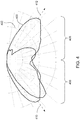
- Figure 4 illustrates an exit distribution 400 of the light emanating from the lighting device 100 shown in Figure 1 according to one example.
- the distribution 400 is shown on a radiation diagram 402 representative of different luminous intensity levels of the light emanating from the lighting device 100 at different angles from a center axis 404 (shown in Figure 1 ) of the lighting device 100.
- the distribution 400 is a non-Lambertian distribution.
- the distribution 400 of light is not equal in all directions or angles from the center axis 404 of the lighting device 100.
- the distribution 400 has a batwing shape in that the distribution 400 includes two approximately oval shaped portions 406, 408 that are elongated along transversely oriented directions 410, 412.
- the distribution 400 may have another shape.
- FIG. 5 illustrates a flowchart of one embodiment of a method 500 for generating light from a lighting device.
- the method 500 may describe operation of the lighting device 100 shown in Figure 1 or may describe operation of another lighting device.
- monochromatic light is generated from one or more point light sources.
- this light is received at a phosphor body.
- the phosphor body may be spaced apart from the point light sources to prevent heating of the phosphor body by the light sources.
- a multi-wavelength light is provided via luminescence of the phosphor body. This multi-wavelength light is emitted across a multi-dimensional surface.
- the phosphor body can convert the points of light from the point light sources into light that emanates from the phosphor body across a two- or three-dimensional surface.
- the light that emanates from the phosphor body is reflected and/or refracted by a lens body to generate a designated distribution of the light.
- 508 may not be included in the method 500.
- the light can be reflected and/or refracted to generate a distribution of the light that is not a Lambertian distribution.
- a lighting device in one embodiment, includes a first point light source configured to generate monochromatic light and a phosphor body spatially separated from the first point light source.
- the phosphor body is configured to receive the monochromatic light generated by the first point light source and provide a mutli-wavelength light through luminescence across a multi-dimensional surface from receipt of the monochromatic light.
- the lighting device also can include a lens body configured to receive the multi-wavelength light from the multi-dimensional surface and both reflect and refract the multi-wavelength light in an exit distribution out of the lens body.
- the first point light source is a light emitting diode.
- the lighting device also includes one or more second point light sources configured to generate additional monochromatic light.
- the phosphor body also is spatially separated from the one or more second point light sources and is configured to receive the additional monochromatic light from the one or more second point light sources.
- the phosphor body also can be configured to provide the multi-wavelength light through luminescence from receipt of the monochromatic light and the additional monochromatic light.
- the phosphor body is spatially separated from the first point light source by an air gap.
- the phosphor body is configured to emit the multi-wavelength light from the multi-dimensional surface having a surface area larger than the first point light source.
- the first point light source is configured to generate a blue light as the monochromatic light.
- the lens body is configured to reflect and refract the multi-wavelength light in a non-Lambertian distribution as the exit distribution.
- the lighting device also includes a cylindrical housing in which the first point light source and the phosphor body are disposed.
- the cylindrical housing can include a circular exit surface that defines the multi-dimensional surface through which the multi-wavelength light is directed into the lens body.
- the lens body can include a convergent convex surface and opposing divergent convex surfaces with the multi-wavelength light received into the lens body toward the divergent convex surfaces and away from the convergent convex surface.
- the convergent convex surface and the divergent lens surfaces of the lens body provide for total internal reflection of the multi-wavelength light.
- another lighting device in another embodiment, includes a light source configured to generate first light of a first wavelength and a phosphor body spatially separated from the light source.
- the phosphor body is configured to receive the first light generated by the light source and provide a mutli-wavelength light having at least one different wavelength than the first wavelength across a multi-dimensional surface.
- the lighting device may include a lens body configured to receive the multi-wavelength light from the multi-dimensional surface and one or more of reflect or refract the multi-wavelength light in an exit distribution out of the lens body.
- the light source is configured to generate the first light as a monochromatic light.
- the light source is a point light source configured to generate the first light as a point of light.
- the lighting device also includes one or more additional point light sources configured to generate additional second light.
- the phosphor body also is spatially separated from the light source and the one or more additional point light sources and to receive the additional second light from the one or more additional point light sources.
- the phosphor body also can be configured to provide the multi-wavelength light through luminescence from receipt of the first light and the additional second light.
- the phosphor body is spatially separated from the light source by an air gap.
- the phosphor body is configured to emit the multi-wavelength light from the multi-dimensional surface having a surface area larger than a surface of the light source through which the first light is emitted from the light source.
- the lighting device also includes a cylindrical housing in which the light source and the phosphor body are disposed.
- the cylindrical housing can have a circular exit surface that defines the multi-dimensional surface through which the multi-wavelength light is directed into the lens body.
- the lens body includes a convergent convex surface and opposing divergent convex surfaces with the multi-wavelength light received into the lens body toward the divergent convex surfaces and away from the convergent convex surface.
- a method (e.g., for generating light) includes generating monochromatic light from a first point light source of a lighting device, receiving the monochromatic light generated by the first point light source at a phosphor body that is spatially separated from the first point light source, providing a mutli-wavelength light through luminescence of the phosphor body across a multi-dimensional surface from receipt of the monochromatic light, and reflecting and refracting the multi-wavelength light with a lens body that receives the multi-wavelength light from the multi-dimensional surface to direct the multi-wavelength light from the lighting device in an exit distribution out of the lens body.
- generating the monochromatic light includes generating additional monochromatic light with one or more second point light sources of the lighting device and receiving the additional monochromatic light at the phosphor body.
- receiving the monochromatic light includes receiving the monochromatic light after the monochromatic light has traversed an air gap between the phosphor body and the first point light.
- reflecting and refracting the multi-wavelength light includes reflecting and refracting the multi-wavelength light in a non-Lambertian distribution as the exit distribution.
Landscapes
- Engineering & Computer Science (AREA)
- General Engineering & Computer Science (AREA)
- Physics & Mathematics (AREA)
- Spectroscopy & Molecular Physics (AREA)
- Microelectronics & Electronic Packaging (AREA)
- Optics & Photonics (AREA)
- Non-Portable Lighting Devices Or Systems Thereof (AREA)
- Led Device Packages (AREA)
- Optical Filters (AREA)
Applications Claiming Priority (1)
| Application Number | Priority Date | Filing Date | Title |
|---|---|---|---|
| US14/886,781 US9970629B2 (en) | 2015-10-19 | 2015-10-19 | Remote phosphor lighting devices and methods |
Publications (1)
| Publication Number | Publication Date |
|---|---|
| EP3159595A1 true EP3159595A1 (en) | 2017-04-26 |
Family
ID=57226760
Family Applications (1)
| Application Number | Title | Priority Date | Filing Date |
|---|---|---|---|
| EP16194150.5A Withdrawn EP3159595A1 (en) | 2015-10-19 | 2016-10-17 | Remote phosphor lighting devices and methods |
Country Status (11)
| Country | Link |
|---|---|
| US (1) | US9970629B2 (zh) |
| EP (1) | EP3159595A1 (zh) |
| JP (1) | JP6868995B2 (zh) |
| KR (1) | KR20170045723A (zh) |
| CN (1) | CN106813118A (zh) |
| AU (1) | AU2016244183A1 (zh) |
| BR (1) | BR102016024252A2 (zh) |
| CA (1) | CA2944470C (zh) |
| MX (1) | MX2016013679A (zh) |
| MY (1) | MY178851A (zh) |
| TW (1) | TWI646284B (zh) |
Citations (9)
| Publication number | Priority date | Publication date | Assignee | Title |
|---|---|---|---|---|
| US20100177495A1 (en) * | 2007-06-05 | 2010-07-15 | Koninklijke Philips Electronics N.V. | Illumination system, collimator and spotlight |
| US20110121758A1 (en) * | 2006-12-15 | 2011-05-26 | Koninklijke Philips Electronics N.V. | Tunable white point light source using a wavelength converting element |
| JP2011113755A (ja) * | 2009-11-25 | 2011-06-09 | Panasonic Electric Works Co Ltd | 発光装置 |
| US20120074833A1 (en) * | 2010-09-28 | 2012-03-29 | Intematix Corporation | Solid-state light emitting devices with photoluminescence wavelength conversion |
| US20130088852A1 (en) * | 2010-05-13 | 2013-04-11 | Olympus Corporation | Illumination apparatus |
| WO2014177607A1 (en) * | 2013-05-03 | 2014-11-06 | Koninklijke Philips N.V. | Light source with adapted spectal output |
| US20150176777A1 (en) * | 2012-04-05 | 2015-06-25 | Koninklijke Philips N.V. | Full spectrum light emitting arrangement |
| US20150252964A1 (en) * | 2014-03-05 | 2015-09-10 | Sharp Kabushiki Kaisha | Light source device and illumination apparatus |
| US9150784B1 (en) * | 2014-10-30 | 2015-10-06 | Osram Opto Semiconductors Gmbh | Lighting modules, lighting apparatus and electronic devices |
Family Cites Families (12)
| Publication number | Priority date | Publication date | Assignee | Title |
|---|---|---|---|---|
| JP2001201611A (ja) | 2000-01-21 | 2001-07-27 | Hitachi Ltd | 光学的機能性シート及びこれを用いた面状光源並びに画像表示装置 |
| US7564612B2 (en) * | 2004-09-27 | 2009-07-21 | Idc, Llc | Photonic MEMS and structures |
| JP2007171319A (ja) * | 2005-12-20 | 2007-07-05 | Samsung Electronics Co Ltd | 照明光学系、それを用いた照明ユニットおよび画像投影装置 |
| KR100789951B1 (ko) | 2006-06-09 | 2008-01-03 | 엘지전자 주식회사 | 발광 유닛 제작 장치 및 방법 |
| JP2010514187A (ja) * | 2006-12-21 | 2010-04-30 | コーニンクレッカ フィリップス エレクトロニクス エヌ ヴィ | 有形の波長変換器を有する発光装置 |
| CN102301176B (zh) * | 2009-01-28 | 2014-02-05 | 皇家飞利浦电子股份有限公司 | 具有远程磷光体层和/或散射层的照明系统 |
| WO2012060319A1 (ja) * | 2010-11-04 | 2012-05-10 | コニカミノルタオプト株式会社 | 光学素子及び照明装置 |
| JP5899508B2 (ja) * | 2011-04-28 | 2016-04-06 | パナソニックIpマネジメント株式会社 | 発光装置及びそれを用いた照明装置 |
| WO2012158414A1 (en) * | 2011-05-13 | 2012-11-22 | 3M Innovative Properties Company | Back-lit transmissive display having variable index light extraction layer |
| US8485692B2 (en) * | 2011-09-09 | 2013-07-16 | Xicato, Inc. | LED-based light source with sharply defined field angle |
| KR20130104628A (ko) * | 2012-03-14 | 2013-09-25 | 서울반도체 주식회사 | Led 조명 모듈 |
| US9410675B1 (en) * | 2015-03-17 | 2016-08-09 | Kevin McDermott | Elongated beam light emitting diode lighting device |
-
2015
- 2015-10-19 US US14/886,781 patent/US9970629B2/en active Active
-
2016
- 2016-09-26 MY MYPI2016703520A patent/MY178851A/en unknown
- 2016-10-05 TW TW105132230A patent/TWI646284B/zh not_active IP Right Cessation
- 2016-10-06 CA CA2944470A patent/CA2944470C/en active Active
- 2016-10-11 AU AU2016244183A patent/AU2016244183A1/en not_active Abandoned
- 2016-10-12 JP JP2016200502A patent/JP6868995B2/ja active Active
- 2016-10-14 KR KR1020160133496A patent/KR20170045723A/ko active Search and Examination
- 2016-10-17 EP EP16194150.5A patent/EP3159595A1/en not_active Withdrawn
- 2016-10-18 MX MX2016013679A patent/MX2016013679A/es active IP Right Grant
- 2016-10-18 BR BR102016024252A patent/BR102016024252A2/pt not_active Application Discontinuation
- 2016-10-19 CN CN201610909566.5A patent/CN106813118A/zh active Pending
Patent Citations (9)
| Publication number | Priority date | Publication date | Assignee | Title |
|---|---|---|---|---|
| US20110121758A1 (en) * | 2006-12-15 | 2011-05-26 | Koninklijke Philips Electronics N.V. | Tunable white point light source using a wavelength converting element |
| US20100177495A1 (en) * | 2007-06-05 | 2010-07-15 | Koninklijke Philips Electronics N.V. | Illumination system, collimator and spotlight |
| JP2011113755A (ja) * | 2009-11-25 | 2011-06-09 | Panasonic Electric Works Co Ltd | 発光装置 |
| US20130088852A1 (en) * | 2010-05-13 | 2013-04-11 | Olympus Corporation | Illumination apparatus |
| US20120074833A1 (en) * | 2010-09-28 | 2012-03-29 | Intematix Corporation | Solid-state light emitting devices with photoluminescence wavelength conversion |
| US20150176777A1 (en) * | 2012-04-05 | 2015-06-25 | Koninklijke Philips N.V. | Full spectrum light emitting arrangement |
| WO2014177607A1 (en) * | 2013-05-03 | 2014-11-06 | Koninklijke Philips N.V. | Light source with adapted spectal output |
| US20150252964A1 (en) * | 2014-03-05 | 2015-09-10 | Sharp Kabushiki Kaisha | Light source device and illumination apparatus |
| US9150784B1 (en) * | 2014-10-30 | 2015-10-06 | Osram Opto Semiconductors Gmbh | Lighting modules, lighting apparatus and electronic devices |
Also Published As
| Publication number | Publication date |
|---|---|
| US20170108179A1 (en) | 2017-04-20 |
| AU2016244183A1 (en) | 2017-05-04 |
| KR20170045723A (ko) | 2017-04-27 |
| TWI646284B (zh) | 2019-01-01 |
| JP2017079210A (ja) | 2017-04-27 |
| MY178851A (en) | 2020-10-21 |
| TW201727137A (zh) | 2017-08-01 |
| JP6868995B2 (ja) | 2021-05-12 |
| MX2016013679A (es) | 2018-04-17 |
| CN106813118A (zh) | 2017-06-09 |
| US9970629B2 (en) | 2018-05-15 |
| BR102016024252A2 (pt) | 2017-05-02 |
| CA2944470C (en) | 2020-04-07 |
| CA2944470A1 (en) | 2017-04-19 |
Similar Documents
| Publication | Publication Date | Title |
|---|---|---|
| US9903550B2 (en) | Lighting device with light mixing element and luminescent volume | |
| US8485692B2 (en) | LED-based light source with sharply defined field angle | |
| EP3046154B1 (en) | Light emitting apparatus | |
| CN105556374A (zh) | 用于产生均匀照明的光学系统 | |
| AU2016204281B2 (en) | Optical system and lighting device comprised thereof | |
| EP2791574B1 (en) | Optical arrangement with diffractive optics | |
| US20150192257A1 (en) | Narrow-beam optic and lighting system using same | |
| CN103782085B (zh) | 光学装置,尤其是用于机动车辆的光学装置 | |
| US10139067B2 (en) | Laser car lamp | |
| US20060139933A1 (en) | Reflector with negative focal length | |
| US9970629B2 (en) | Remote phosphor lighting devices and methods | |
| RU2317612C1 (ru) | Светодиодное устройство | |
| US9423085B2 (en) | Beam shaping light emitting module | |
| JP2015002025A (ja) | 照明装置 | |
| RU2626059C1 (ru) | Способ рециркуляции света и светодиодный модуль рециркуляции |
Legal Events
| Date | Code | Title | Description |
|---|---|---|---|
| PUAI | Public reference made under article 153(3) epc to a published international application that has entered the european phase |
Free format text: ORIGINAL CODE: 0009012 |
|
| STAA | Information on the status of an ep patent application or granted ep patent |
Free format text: STATUS: THE APPLICATION HAS BEEN PUBLISHED |
|
| AK | Designated contracting states |
Kind code of ref document: A1 Designated state(s): AL AT BE BG CH CY CZ DE DK EE ES FI FR GB GR HR HU IE IS IT LI LT LU LV MC MK MT NL NO PL PT RO RS SE SI SK SM TR |
|
| AX | Request for extension of the european patent |
Extension state: BA ME |
|
| STAA | Information on the status of an ep patent application or granted ep patent |
Free format text: STATUS: REQUEST FOR EXAMINATION WAS MADE |
|
| 17P | Request for examination filed |
Effective date: 20171026 |
|
| RBV | Designated contracting states (corrected) |
Designated state(s): AL AT BE BG CH CY CZ DE DK EE ES FI FR GB GR HR HU IE IS IT LI LT LU LV MC MK MT NL NO PL PT RO RS SE SI SK SM TR |
|
| STAA | Information on the status of an ep patent application or granted ep patent |
Free format text: STATUS: EXAMINATION IS IN PROGRESS |
|
| 17Q | First examination report despatched |
Effective date: 20181128 |
|
| STAA | Information on the status of an ep patent application or granted ep patent |
Free format text: STATUS: EXAMINATION IS IN PROGRESS |
|
| STAA | Information on the status of an ep patent application or granted ep patent |
Free format text: STATUS: THE APPLICATION IS DEEMED TO BE WITHDRAWN |
|
| 18D | Application deemed to be withdrawn |
Effective date: 20210501 |