EP3159577A2 - Actuator - Google Patents
Actuator Download PDFInfo
- Publication number
- EP3159577A2 EP3159577A2 EP16200900.5A EP16200900A EP3159577A2 EP 3159577 A2 EP3159577 A2 EP 3159577A2 EP 16200900 A EP16200900 A EP 16200900A EP 3159577 A2 EP3159577 A2 EP 3159577A2
- Authority
- EP
- European Patent Office
- Prior art keywords
- component
- helical
- bearing system
- roller bearings
- grooves
- Prior art date
- Legal status (The legal status is an assumption and is not a legal conclusion. Google has not performed a legal analysis and makes no representation as to the accuracy of the status listed.)
- Granted
Links
Images

Classifications
-
- F—MECHANICAL ENGINEERING; LIGHTING; HEATING; WEAPONS; BLASTING
- F16—ENGINEERING ELEMENTS AND UNITS; GENERAL MEASURES FOR PRODUCING AND MAINTAINING EFFECTIVE FUNCTIONING OF MACHINES OR INSTALLATIONS; THERMAL INSULATION IN GENERAL
- F16H—GEARING
- F16H25/00—Gearings comprising primarily only cams, cam-followers and screw-and-nut mechanisms
- F16H25/18—Gearings comprising primarily only cams, cam-followers and screw-and-nut mechanisms for conveying or interconverting oscillating or reciprocating motions
- F16H25/20—Screw mechanisms
- F16H25/22—Screw mechanisms with balls, rollers, or similar members between the co-operating parts; Elements essential to the use of such members
- F16H25/2204—Screw mechanisms with balls, rollers, or similar members between the co-operating parts; Elements essential to the use of such members with balls
- F16H25/2214—Screw mechanisms with balls, rollers, or similar members between the co-operating parts; Elements essential to the use of such members with balls with elements for guiding the circulating balls
-
- B—PERFORMING OPERATIONS; TRANSPORTING
- B64—AIRCRAFT; AVIATION; COSMONAUTICS
- B64C—AEROPLANES; HELICOPTERS
- B64C13/00—Control systems or transmitting systems for actuating flying-control surfaces, lift-increasing flaps, air brakes, or spoilers
- B64C13/24—Transmitting means
- B64C13/26—Transmitting means without power amplification or where power amplification is irrelevant
- B64C13/28—Transmitting means without power amplification or where power amplification is irrelevant mechanical
- B64C13/32—Transmitting means without power amplification or where power amplification is irrelevant mechanical using cam mechanisms
-
- F—MECHANICAL ENGINEERING; LIGHTING; HEATING; WEAPONS; BLASTING
- F16—ENGINEERING ELEMENTS AND UNITS; GENERAL MEASURES FOR PRODUCING AND MAINTAINING EFFECTIVE FUNCTIONING OF MACHINES OR INSTALLATIONS; THERMAL INSULATION IN GENERAL
- F16C—SHAFTS; FLEXIBLE SHAFTS; ELEMENTS OR CRANKSHAFT MECHANISMS; ROTARY BODIES OTHER THAN GEARING ELEMENTS; BEARINGS
- F16C29/00—Bearings for parts moving only linearly
- F16C29/04—Ball or roller bearings
- F16C29/06—Ball or roller bearings in which the rolling bodies circulate partly without carrying load
- F16C29/068—Ball or roller bearings in which the rolling bodies circulate partly without carrying load with the bearing body fully encircling the guide rail or track
-
- F—MECHANICAL ENGINEERING; LIGHTING; HEATING; WEAPONS; BLASTING
- F16—ENGINEERING ELEMENTS AND UNITS; GENERAL MEASURES FOR PRODUCING AND MAINTAINING EFFECTIVE FUNCTIONING OF MACHINES OR INSTALLATIONS; THERMAL INSULATION IN GENERAL
- F16C—SHAFTS; FLEXIBLE SHAFTS; ELEMENTS OR CRANKSHAFT MECHANISMS; ROTARY BODIES OTHER THAN GEARING ELEMENTS; BEARINGS
- F16C29/00—Bearings for parts moving only linearly
- F16C29/04—Ball or roller bearings
- F16C29/06—Ball or roller bearings in which the rolling bodies circulate partly without carrying load
- F16C29/068—Ball or roller bearings in which the rolling bodies circulate partly without carrying load with the bearing body fully encircling the guide rail or track
- F16C29/0692—Ball or roller bearings in which the rolling bodies circulate partly without carrying load with the bearing body fully encircling the guide rail or track the bearing body encircles a guide rail or track of non-circular cross-section, e.g. with grooves or protrusions, i.e. the linear bearing is suited to transmit torque
-
- F—MECHANICAL ENGINEERING; LIGHTING; HEATING; WEAPONS; BLASTING
- F16—ENGINEERING ELEMENTS AND UNITS; GENERAL MEASURES FOR PRODUCING AND MAINTAINING EFFECTIVE FUNCTIONING OF MACHINES OR INSTALLATIONS; THERMAL INSULATION IN GENERAL
- F16H—GEARING
- F16H25/00—Gearings comprising primarily only cams, cam-followers and screw-and-nut mechanisms
- F16H25/18—Gearings comprising primarily only cams, cam-followers and screw-and-nut mechanisms for conveying or interconverting oscillating or reciprocating motions
- F16H25/186—Gearings comprising primarily only cams, cam-followers and screw-and-nut mechanisms for conveying or interconverting oscillating or reciprocating motions with reciprocation along the axis of oscillation
-
- F—MECHANICAL ENGINEERING; LIGHTING; HEATING; WEAPONS; BLASTING
- F16—ENGINEERING ELEMENTS AND UNITS; GENERAL MEASURES FOR PRODUCING AND MAINTAINING EFFECTIVE FUNCTIONING OF MACHINES OR INSTALLATIONS; THERMAL INSULATION IN GENERAL
- F16H—GEARING
- F16H25/00—Gearings comprising primarily only cams, cam-followers and screw-and-nut mechanisms
- F16H25/18—Gearings comprising primarily only cams, cam-followers and screw-and-nut mechanisms for conveying or interconverting oscillating or reciprocating motions
- F16H25/20—Screw mechanisms
-
- F—MECHANICAL ENGINEERING; LIGHTING; HEATING; WEAPONS; BLASTING
- F16—ENGINEERING ELEMENTS AND UNITS; GENERAL MEASURES FOR PRODUCING AND MAINTAINING EFFECTIVE FUNCTIONING OF MACHINES OR INSTALLATIONS; THERMAL INSULATION IN GENERAL
- F16C—SHAFTS; FLEXIBLE SHAFTS; ELEMENTS OR CRANKSHAFT MECHANISMS; ROTARY BODIES OTHER THAN GEARING ELEMENTS; BEARINGS
- F16C2326/00—Articles relating to transporting
- F16C2326/43—Aeroplanes; Helicopters
-
- F—MECHANICAL ENGINEERING; LIGHTING; HEATING; WEAPONS; BLASTING
- F16—ENGINEERING ELEMENTS AND UNITS; GENERAL MEASURES FOR PRODUCING AND MAINTAINING EFFECTIVE FUNCTIONING OF MACHINES OR INSTALLATIONS; THERMAL INSULATION IN GENERAL
- F16H—GEARING
- F16H25/00—Gearings comprising primarily only cams, cam-followers and screw-and-nut mechanisms
- F16H25/18—Gearings comprising primarily only cams, cam-followers and screw-and-nut mechanisms for conveying or interconverting oscillating or reciprocating motions
- F16H25/20—Screw mechanisms
- F16H2025/2028—Screw mechanisms using screw profiles with high efficiency for converting reciprocating motion into oscillating movement
-
- F—MECHANICAL ENGINEERING; LIGHTING; HEATING; WEAPONS; BLASTING
- F16—ENGINEERING ELEMENTS AND UNITS; GENERAL MEASURES FOR PRODUCING AND MAINTAINING EFFECTIVE FUNCTIONING OF MACHINES OR INSTALLATIONS; THERMAL INSULATION IN GENERAL
- F16H—GEARING
- F16H25/00—Gearings comprising primarily only cams, cam-followers and screw-and-nut mechanisms
- F16H25/18—Gearings comprising primarily only cams, cam-followers and screw-and-nut mechanisms for conveying or interconverting oscillating or reciprocating motions
- F16H25/20—Screw mechanisms
- F16H2025/2062—Arrangements for driving the actuator
- F16H2025/2075—Coaxial drive motors
-
- F—MECHANICAL ENGINEERING; LIGHTING; HEATING; WEAPONS; BLASTING
- F16—ENGINEERING ELEMENTS AND UNITS; GENERAL MEASURES FOR PRODUCING AND MAINTAINING EFFECTIVE FUNCTIONING OF MACHINES OR INSTALLATIONS; THERMAL INSULATION IN GENERAL
- F16H—GEARING
- F16H25/00—Gearings comprising primarily only cams, cam-followers and screw-and-nut mechanisms
- F16H25/18—Gearings comprising primarily only cams, cam-followers and screw-and-nut mechanisms for conveying or interconverting oscillating or reciprocating motions
- F16H25/20—Screw mechanisms
- F16H25/22—Screw mechanisms with balls, rollers, or similar members between the co-operating parts; Elements essential to the use of such members
- F16H25/2247—Screw mechanisms with balls, rollers, or similar members between the co-operating parts; Elements essential to the use of such members with rollers
Definitions
- the present disclosure generally relates to an actuator for driving a rotatable component, and a bearing system for use in an actuator.
- Actuators may be used in, for example, aerospace applications, to drive primary control systems such as ailerons, elevators or rudders.
- primary control systems such as ailerons, elevators or rudders.
- actuators are hydraulic, and use fluid transfer between two or more reservoirs of hydraulic fluid as a means for controlling the position of the control systems.
- the present disclosure is aimed at improving actuators that are used to drive rotatable components.
- an actuator for driving a rotatable component comprising:
- the disclosure involves converting rotational movement of the first member, for example a ball screw, to axial reciprocating movement of the third member and first or second member, preferably via the nut, and then a further conversion of this reciprocating movement to rotational movement of the component, for example arms of the actuator.
- This is an improvement over conventional methods of driving a rotatable component that use hydraulics, for example.
- the first member and/or second member and/or third member and/or fourth member may be substantially tubular or cylindrical.
- the first and fourth member may be restricted against axial movement and second and third member may be restricted against rotational movement.
- the actuator may be for use in an aircraft or other aerospace applications, for example for driving flight control system components such as ailerons and/or elevators and/or rudders.
- the actuator may be for driving the rotatable component between stowed and deployed positions and/or between unextended and extended positions.
- the bearing system may comprise one or a plurality of roller bearings moveable along a helical track located on said third or fourth member, wherein optionally, upon the axial movement of said first and third member, said roller bearings apply a force to said track, or said track applies a force to said roller bearings, so as to cause rotation of said fourth member to drive said component.
- the first member may be fixed in an axial or longitudinal direction, and rotation of the first member may cause axial movement of the second and third member.
- the second member may be fixed in an axial or longitudinal direction and rotation of the first member may cause axial movement of the first and third member.
- Roller bearings may be interposed between the third and fourth member, wherein the roller bearings optionally apply a rotational force to the fourth member upon axial movement of the third member.
- the fourth member may comprise the helical track, which helical track may comprise two opposing rails, and the one or a plurality of roller bearings may be axially moveable with the third member and may contact both of the rails. Upon axial movement of the third member, the roller bearings may apply a force to the helical track, for example at least one of the rails, so as to cause rotation of the fourth member to drive the component.
- the third member may comprise the helical track, which helical track may comprise two opposing rails, and the one or a plurality of roller bearings may be rotatably moveable with the fourth member and may contact both of the rails.
- the helical track for example the opposing rails, may apply a force to the roller bearings so as to cause rotation of the fourth member to drive the component.
- the opposing rails may be parallel.
- the rotational movement of the fourth member is due to the helical nature of the helical track, and may be further assisted by restricting the axial movement of the fourth member and/or the rotational movement of the third member.
- the third member may comprise a slider, or sliding portion, that is restricted against rotational movement, and the slider, or sliding portion, may comprise the bearing system as described herein.
- the bearing system may comprise roller bearings, or the roller bearings may be, axially moveable with the third member, or rotatable with said fourth member.
- the fourth member may comprise a first helical rail configured to contact the roller bearings, and the third member may comprise a second helical rail configured to contact the roller bearings.
- first helical rail and the second helical rail may be brought into engagement with the roller bearings so as to cause rotation of the fourth member to drive the component.
- the first and second helical rails may be parallel with one another.
- the screw pitch of the first member may be smaller than the pitch of the helical track, first helical rail and/or second helical rail.
- a pitch of the screw of the first member may be at least 5, 10, 20, 50, 100 or 200 times less than a pitch of said helical track, first helical rail and/or second helical rail.
- the ratio between the pitch of the screw of the first member and the pitch of the helical track, first helical rail and/or second helical rail may be less than 1:5, 1:10, 1:20, 1:50, 1:100 or 1:200.
- the first member may be fixed in an axial direction, and rotation of the first member may cause axial movement of the nut; or the nut may be fixed in an axial direction, and rotation of the first member may cause axial movement of the first member.
- the axes of rotation of the first member and fourth member may be coincident or coaxial.
- the axial movement of the first and/or second and/or third member may be along an axis that is coincident or coaxial with the axes of rotation of the first member and the fourth member.
- the rotational range of motion of the third or fourth member may be less than 360 degrees, or less than 270, 180, 90, 60 or 30 degrees.
- the rotational range of motion may be defined by the helical track, first helical rail and/or second helical rail.
- Rotation of the first member may be driven by an electric motor.
- the actuator may be driven by an electric motor.
- the actuator may comprise no hydraulic components.
- the first member may comprise a ball screw, lead screw or roller screw.
- a method of driving a rotatable component comprising:
- the method may further comprise rotating the first member so as to cause axial movement of the first or second and third member, and thereby rotation of the fourth member to drive the component.
- the bearing system described herein is advantagous in its own right. Therefore an aspect of the present disclosure provides a bearing system comprising:
- the helical nature of the first and second helical tracks, in conjunction with the restricted movements of the first and second components in rotational and axial directions respectively, means that an axial force in said first component is transferred to a rotational force in said second component.
- the bearing system may be for use in an actuator, for example an actuator for driving a rotatable component, and/or an actuator for use in an aircraft or other aerospace applications, for example for driving flight control system elements such as ailerons and/or elevators and/or rudders, or for driving a rotatable component between stowed and deployed positions and/or between unextended and extended positions.
- an actuator for example an actuator for driving a rotatable component
- an actuator for use in an aircraft or other aerospace applications, for example for driving flight control system elements such as ailerons and/or elevators and/or rudders, or for driving a rotatable component between stowed and deployed positions and/or between unextended and extended positions.
- the first component and second component may be substantially cylindrical and/or comprise cylindrical tubes.
- the first component and the second component may comprise concentric cylindrical tubes.
- the first component may be slidably received within the second component.
- the first helical track may comprise a first helical rail
- the second helical track may comprise a second helical rail, such that upon axial movement of the first component, the first helical rail is urged towards the second helical rail.
- the first helical track and/or second helical track may comprise opposing rails.
- the first helical rail and/or second helical rail and/or opposing rails may comprise grooves or protrusions on the first and/or second components respectively.
- the first helical track may comprise two helical grooves.
- the second helical track may comprise two helical rails that cooperate with the helical grooves, such that the two helical rails may be slidably received within the helical grooves.
- the roller bearings may be located within the helical grooves, wherein axial contact between the helical grooves and helical rails may be prevented by the roller bearings.
- the first component may comprise two axially separated transverse grooves connecting the helical grooves.
- a central protrusion may be located on the first component between the helical grooves and the transverse grooves.
- the two helical grooves, two transverse grooves, and central protrusion may form a track for the roller bearings, for example an O-shaped track.
- the roller bearings may be positioned within the track in a manner that allows free movement of the roller bearings around the track. In use, the roller bearings may travel around the track upon axial movement of the first component, while transferring force from the first component to the second component.
- One or more further protrusions may be provided on the first component to enclose the track.
- the grooves and protrusions may be provided on an inner or outer surface of the first component, and the rails may be provided on an outer or inner surface of the second component, respectively.
- the first component may be the third member, slider or sliding portion
- the second component may be the fourth member
- Figs. 1 and 2 show an actuator 10 in accordance with the present disclosure.
- the actuator 10 may comprise an electric motor (not shown) that is configured to rotate a first member, in the form of ball screw 12.
- the ball screw 12 may be fixed against movement in an axial or longitudinal direction by bearings 13.
- a second member, comprising nut 14 is threaded to said ball screw and is moveable in the longitudinal direction.
- rotation of the screw 12 causes nut 14 to move longitudinally along the length of the screw 12.
- the second member may comprise one or more moveable rods 16 fixed to the nut 14 that extend in a longitudinal direction, through an intermediate housing 18 of the actuator 10.
- the one or more rods 16 may be coupled with a third member in the form of a slider 20 that forms part of the second member as well.
- the slider 20 moves in the axial or longitudinal direction along one or more fixed rods 19.
- the one or more fixed rods 19 restrict or prevent rotational movement of the slider.
- the slider 20 is of tubular form (see Fig. 4B ).
- a fourth, rotating member, in the form of a sleeve 30 may be coupled to the slider 20 via a bearing system 50.
- the bearing system 50 comprises one or more low friction roller bearings 52 that move with the slider 20.
- the roller bearings 52 are also restricted against rotational movement. Therefore, the roller bearings 52 move as a unit in the axial or longitudinal direction with the slider 20.
- the sleeve 30 is of tubular form (see Fig. 4A ) and encloses the slider 20. In other words the slider 20 may be slidably received within the sleeve 30.
- the helical track 54 has a longitudinal axis that is offset from the longitudinal axis of the sleeve 30.
- the helical track 54 may comprise two helical rails.
- the roller bearings 52 are configured to contact the helical track 54, and may sit within the two helical rails as shown in Fig. 2 . It will be appreciated that the roller bearings 52 move only in the axial or longitudinal direction, as they are restricted from rotational movement. Therefore, upon axial movement of the slider 20, the roller bearings 52 move along the helical track. Due to the helical nature of the track, this causes the roller bearings 52 to push against the track and rotate the sleeve 30.
- the helical track 54 may have a high pitch, such that the roller bearings 52 easily move along the helical track 54 upon axial movement of the slider 20.
- the high pitch also means that the axial force from the roller bearings 52 is easily transferred to a rotational force of the sleeve 30, and the actuator has a high torque.
- the helical track 54 may extend around less than 360 degrees, 270 degrees, 180 degrees, 90 degrees, 60 degrees or 30 degrees of the circumference of the sleeve 30.
- the rotational range of motion of the sleeve may be less than 360 degrees, 270 degrees, 180 degrees, 90 degrees, 60 degrees or 30 degrees respectively.
- the rotational range of motion is 60 degrees.
- the pitch of the ball screw 12 is much lower than that of the helical track 54, and optionally at least 50 times lower, for example 130 times lower.
- the pitch of the ball screw may be less than 25, 10, 5 or 2 mm, and the pitch of the helical track may be greater than 100, 250, 500 or 1000 mm.
- the sleeve 30 may have actuator arms 35 connected to it, and rotation of the sleeve 30 causes actuator arms 35 to rotate as well.
- the actuator arms 35 may comprise part of, or be coupled to, a rotatable component, for example an aircraft flight control system element such as one or more ailerons and/or elevators and/or rudders. In this manner, the actuator drives the rotatable component.
- the second member comprising nut 14 could be fixed in the axial or longitudinal direction, and the first member or ball screw 12 could move in the axial or longitudinal direction to cause moveable rods 16 and slider 20 to also move in the axial or longitudinal direction.
- the first member or ball screw 12 may be connected or coupled to the moveable rods 16 and slider 20 and/or the fourth member.
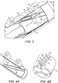
- Figs. 3, 4A and 4B show the bearing system 50 in detail.
- the sleeve 30 comprises one or more helical tracks 54, which as described above may comprise two helical rails 56, each having a longitudinal axis that is offset from the longitudinal axis of the sleeve 30.
- the slider 20 comprises a groove arrangement 21 comprising two helical grooves 22, each having a longitudinal axis that is offset from the longitudinal axis of the slider 20.
- the groove arrangement 21 may further comprise two end protrusions 26 and a central protrusion 28 between the grooves 22, as well as two lateral grooves 24 that interconnect the pair of helical grooves 22.
- the protrusions 26, 28 are sized such that the helical rails 56 are slidably received within the helical grooves 22 and end protrusions 26.
- the central protrusion 28 is sized such that the roller bearings 52 fit circumferentially between the helical rails 56 and the central protrusion 28.
- the end protrusions 26 are sized such that the roller bearings 52 do not fit circumferentially between the helical rails 56 and the end protrusions 26.
- the lateral grooves 24 are sized such that the roller bearings 52 can travel between the helical grooves 22 via the lateral grooves 24.
- a groove arrangement 21, for example as described above, may be provided on the first or second member and may form a closed pathway for the roller bearings 52, or rollers, to move around upon axial movement of the first or second member, for example the slider 20, whilst still pushing against the helical track 54 so as to transfer the axial force of the first or second member to the helical track 54, in turn causing rotational movement of the third member.
- a groove arrangement 21 as described above may alternatively be provided on the fourth member, and the groove arrangement 21, as well as roller bearings 52, may be rotationally moveable with the fourth member and may form a closed pathway for the roller bearings, or rollers, to move around upon axial movement of the third member.
- a helical track 54 for example as described above, may be provided on the axially moveable third member, and the helical track 54 would push against the roller bearings 52 so as to transfer the axial force of the third member to the roller bearings 52, in turn causing rotational movement of the fourth member.
Landscapes
- Engineering & Computer Science (AREA)
- General Engineering & Computer Science (AREA)
- Mechanical Engineering (AREA)
- Automation & Control Theory (AREA)
- Aviation & Aerospace Engineering (AREA)
- Transmission Devices (AREA)
- Bearings For Parts Moving Linearly (AREA)
Abstract
a first, rotating member comprising a screw;
a second member comprising a nut threaded to said screw, wherein rotation of said first member causes axial movement of said first or second member; a third member coupled to the second member, wherein axial movement of said first or second member causes axial movement of said third member
a fourth, rotating member coupled to said third member and connectable to said component; and
a bearing system located between said third member and said fourth member, said bearing system configured to cause said fourth member to rotate upon said axial movement of said third member so as to drive said component.
Description
- The present disclosure generally relates to an actuator for driving a rotatable component, and a bearing system for use in an actuator.
- Actuators may be used in, for example, aerospace applications, to drive primary control systems such as ailerons, elevators or rudders. Conventionally such actuators are hydraulic, and use fluid transfer between two or more reservoirs of hydraulic fluid as a means for controlling the position of the control systems.
- The present disclosure is aimed at improving actuators that are used to drive rotatable components.
- In accordance with an aspect of the present disclosure, there is provided an actuator for driving a rotatable component, comprising:
- a first, rotating member comprising a screw;
- a second member comprising a nut threaded to the screw, wherein rotation of the first member causes axial movement of the first or second member;
- a third member coupled to the first or second member, wherein axial movement of the first or second member causes axial movement of the third member,
- a fourth, rotating member coupled to the third member and connectable to the component; and
- a bearing system located between the third member and the fourth member, the bearing system configured to cause the fourth member to rotate upon the axial movement of third member so as to drive the component.
- The disclosure involves converting rotational movement of the first member, for example a ball screw, to axial reciprocating movement of the third member and first or second member, preferably via the nut, and then a further conversion of this reciprocating movement to rotational movement of the component, for example arms of the actuator. This is an improvement over conventional methods of driving a rotatable component that use hydraulics, for example.
- The first member and/or second member and/or third member and/or fourth member may be substantially tubular or cylindrical. The first and fourth member may be restricted against axial movement and second and third member may be restricted against rotational movement. The actuator may be for use in an aircraft or other aerospace applications, for example for driving flight control system components such as ailerons and/or elevators and/or rudders. The actuator may be for driving the rotatable component between stowed and deployed positions and/or between unextended and extended positions.
- The bearing system may comprise one or a plurality of roller bearings moveable along a helical track located on said third or fourth member, wherein optionally, upon the axial movement of said first and third member, said roller bearings apply a force to said track, or said track applies a force to said roller bearings, so as to cause rotation of said fourth member to drive said component.
- The first member may be fixed in an axial or longitudinal direction, and rotation of the first member may cause axial movement of the second and third member. Alternatively, the second member may be fixed in an axial or longitudinal direction and rotation of the first member may cause axial movement of the first and third member. Roller bearings may be interposed between the third and fourth member, wherein the roller bearings optionally apply a rotational force to the fourth member upon axial movement of the third member.
- The fourth member may comprise the helical track, which helical track may comprise two opposing rails, and the one or a plurality of roller bearings may be axially moveable with the third member and may contact both of the rails. Upon axial movement of the third member, the roller bearings may apply a force to the helical track, for example at least one of the rails, so as to cause rotation of the fourth member to drive the component.
- The third member may comprise the helical track, which helical track may comprise two opposing rails, and the one or a plurality of roller bearings may be rotatably moveable with the fourth member and may contact both of the rails. Upon axial movement of the third member, the helical track, for example the opposing rails, may apply a force to the roller bearings so as to cause rotation of the fourth member to drive the component.
- The opposing rails may be parallel.
- It will be appreciated that the rotational movement of the fourth member is due to the helical nature of the helical track, and may be further assisted by restricting the axial movement of the fourth member and/or the rotational movement of the third member. The third member may comprise a slider, or sliding portion, that is restricted against rotational movement, and the slider, or sliding portion, may comprise the bearing system as described herein.
- The bearing system may comprise roller bearings, or the roller bearings may be, axially moveable with the third member, or rotatable with said fourth member.
- The fourth member may comprise a first helical rail configured to contact the roller bearings, and the third member may comprise a second helical rail configured to contact the roller bearings.
- Upon the axial movement the first helical rail and the second helical rail may be brought into engagement with the roller bearings so as to cause rotation of the fourth member to drive the component.
- The first and second helical rails may be parallel with one another.
- The screw pitch of the first member may be smaller than the pitch of the helical track, first helical rail and/or second helical rail. For example, a pitch of the screw of the first member may be at least 5, 10, 20, 50, 100 or 200 times less than a pitch of said helical track, first helical rail and/or second helical rail. The ratio between the pitch of the screw of the first member and the pitch of the helical track, first helical rail and/or second helical rail may be less than 1:5, 1:10, 1:20, 1:50, 1:100 or 1:200.
- The first member may be fixed in an axial direction, and rotation of the first member may cause axial movement of the nut; or
the nut may be fixed in an axial direction, and rotation of the first member may cause axial movement of the first member. - The axes of rotation of the first member and fourth member may be coincident or coaxial.
- The axial movement of the first and/or second and/or third member may be along an axis that is coincident or coaxial with the axes of rotation of the first member and the fourth member.
- The rotational range of motion of the third or fourth member may be less than 360 degrees, or less than 270, 180, 90, 60 or 30 degrees. The rotational range of motion may be defined by the helical track, first helical rail and/or second helical rail.
- Rotation of the first member may be driven by an electric motor. The actuator may be driven by an electric motor. The actuator may comprise no hydraulic components.
- The first member may comprise a ball screw, lead screw or roller screw.
- In accordance with an aspect of the present disclosure, there is provided a method of driving a rotatable component, comprising:
- providing an actuator as described above.
- The method may further comprise rotating the first member so as to cause axial movement of the first or second and third member, and thereby rotation of the fourth member to drive the component.
- The bearing system described herein is advantagous in its own right. Therefore an aspect of the present disclosure provides a bearing system comprising:
- a first component axially moveable along a first axis;
- a second component rotatable about a second axis, wherein the first component is restricted against rotational movement and the second component is restricted against axial movement;
- wherein the first component comprises a first helical track, and the second component comprises a second helical track that opposes the first helical track;
- one or more roller bearings located between the first helical track and the second helical track, wherein upon axial movement of the first component, the first helical track is urged towards the second helical track such that a force is applied through the roller bearings to the second component so as to rotate the second component about the second axis.
- Force may be transferred from the first component to said second component via the roller bearings. The helical nature of the first and second helical tracks, in conjunction with the restricted movements of the first and second components in rotational and axial directions respectively, means that an axial force in said first component is transferred to a rotational force in said second component.
- The bearing system may be for use in an actuator, for example an actuator for driving a rotatable component, and/or an actuator for use in an aircraft or other aerospace applications, for example for driving flight control system elements such as ailerons and/or elevators and/or rudders, or for driving a rotatable component between stowed and deployed positions and/or between unextended and extended positions.
- The first component and second component may be substantially cylindrical and/or comprise cylindrical tubes. For example, the first component and the second component may comprise concentric cylindrical tubes. The first component may be slidably received within the second component.
- The first helical track may comprise a first helical rail, and the second helical track may comprise a second helical rail, such that upon axial movement of the first component, the first helical rail is urged towards the second helical rail.
- The first helical track and/or second helical track may comprise opposing rails. The first helical rail and/or second helical rail and/or opposing rails may comprise grooves or protrusions on the first and/or second components respectively.
- The first helical track may comprise two helical grooves. The second helical track may comprise two helical rails that cooperate with the helical grooves, such that the two helical rails may be slidably received within the helical grooves. The roller bearings may be located within the helical grooves, wherein axial contact between the helical grooves and helical rails may be prevented by the roller bearings.
- The first component may comprise two axially separated transverse grooves connecting the helical grooves. A central protrusion may be located on the first component between the helical grooves and the transverse grooves. The two helical grooves, two transverse grooves, and central protrusion may form a track for the roller bearings, for example an O-shaped track.
- The roller bearings may be positioned within the track in a manner that allows free movement of the roller bearings around the track. In use, the roller bearings may travel around the track upon axial movement of the first component, while transferring force from the first component to the second component. One or more further protrusions may be provided on the first component to enclose the track. The grooves and protrusions may be provided on an inner or outer surface of the first component, and the rails may be provided on an outer or inner surface of the second component, respectively.
- Any of the embodiments of the bearing system described above may be used as the bearing system in the actuator described above. In this case, the first component may be the third member, slider or sliding portion, and the second component may be the fourth member.
- In accordance with an aspect of this disclosure, there is provided a method of operating the bearing system described above, comprising:
- moving the first component in an axial direction, so as to cause rotation of the second component.
- Various embodiments will now be described, by way of example only, and with reference to the accompanying drawings in which:
-
Fig. 1 shows a cross-section of an actuator in accordance with this disclosure; -
Fig. 2 shows a perspective view of the actuator ofFig. 1 ; -
Fig. 3 shows a bearing system in accordance with this disclosure; and -
Figs. 4A and 4B show components of the bearing system ofFig. 3 . -
Figs. 1 and 2 show an actuator 10 in accordance with the present disclosure. - The
actuator 10 may comprise an electric motor (not shown) that is configured to rotate a first member, in the form ofball screw 12. The ball screw 12 may be fixed against movement in an axial or longitudinal direction bybearings 13. A second member, comprisingnut 14 is threaded to said ball screw and is moveable in the longitudinal direction. Thus, rotation of thescrew 12causes nut 14 to move longitudinally along the length of thescrew 12. - The second member may comprise one or more
moveable rods 16 fixed to thenut 14 that extend in a longitudinal direction, through anintermediate housing 18 of theactuator 10. The one ormore rods 16 may be coupled with a third member in the form of aslider 20 that forms part of the second member as well. Theslider 20 moves in the axial or longitudinal direction along one or morefixed rods 19. The one or morefixed rods 19 restrict or prevent rotational movement of the slider. Theslider 20 is of tubular form (seeFig. 4B ). - Thus, upon rotation of the
screw 12 thenut 14 moves in the axial or longitudinal direction. This causesmoveable rods 16 andslider 20 to also move in the axial or longitudinal direction. - A fourth, rotating member, in the form of a
sleeve 30 may be coupled to theslider 20 via abearing system 50. The bearingsystem 50 comprises one or more lowfriction roller bearings 52 that move with theslider 20. As theslider 20 is restricted against rotational movement, theroller bearings 52 are also restricted against rotational movement. Therefore, theroller bearings 52 move as a unit in the axial or longitudinal direction with theslider 20. Thesleeve 30 is of tubular form (seeFig. 4A ) and encloses theslider 20. In other words theslider 20 may be slidably received within thesleeve 30. - One or more
helical tracks 54 are provided on thesleeve 30. Thehelical track 54 has a longitudinal axis that is offset from the longitudinal axis of thesleeve 30. Thehelical track 54 may comprise two helical rails. Theroller bearings 52 are configured to contact thehelical track 54, and may sit within the two helical rails as shown inFig. 2 . It will be appreciated that theroller bearings 52 move only in the axial or longitudinal direction, as they are restricted from rotational movement. Therefore, upon axial movement of theslider 20, theroller bearings 52 move along the helical track. Due to the helical nature of the track, this causes theroller bearings 52 to push against the track and rotate thesleeve 30. - The
helical track 54 may have a high pitch, such that theroller bearings 52 easily move along thehelical track 54 upon axial movement of theslider 20. The high pitch also means that the axial force from theroller bearings 52 is easily transferred to a rotational force of thesleeve 30, and the actuator has a high torque. - For example, the
helical track 54 may extend around less than 360 degrees, 270 degrees, 180 degrees, 90 degrees, 60 degrees or 30 degrees of the circumference of thesleeve 30. In other words, the rotational range of motion of the sleeve may be less than 360 degrees, 270 degrees, 180 degrees, 90 degrees, 60 degrees or 30 degrees respectively. In the illustrated example, the rotational range of motion is 60 degrees. - The pitch of the
ball screw 12 is much lower than that of thehelical track 54, and optionally at least 50 times lower, for example 130 times lower. The pitch of the ball screw may be less than 25, 10, 5 or 2 mm, and the pitch of the helical track may be greater than 100, 250, 500 or 1000 mm. - The
sleeve 30 may haveactuator arms 35 connected to it, and rotation of thesleeve 30 causes actuatorarms 35 to rotate as well. Theactuator arms 35 may comprise part of, or be coupled to, a rotatable component, for example an aircraft flight control system element such as one or more ailerons and/or elevators and/or rudders. In this manner, the actuator drives the rotatable component. - In other arrangements, the second member, comprising
nut 14 could be fixed in the axial or longitudinal direction, and the first member or ball screw 12 could move in the axial or longitudinal direction to causemoveable rods 16 andslider 20 to also move in the axial or longitudinal direction. In these embodiments, the first member or ball screw 12 may be connected or coupled to themoveable rods 16 andslider 20 and/or the fourth member. -
Figs. 3, 4A and 4B show the bearingsystem 50 in detail. - The
sleeve 30 comprises one or morehelical tracks 54, which as described above may comprise twohelical rails 56, each having a longitudinal axis that is offset from the longitudinal axis of thesleeve 30. - The
slider 20 comprises agroove arrangement 21 comprising twohelical grooves 22, each having a longitudinal axis that is offset from the longitudinal axis of theslider 20. Thegroove arrangement 21 may further comprise twoend protrusions 26 and acentral protrusion 28 between thegrooves 22, as well as twolateral grooves 24 that interconnect the pair ofhelical grooves 22. - The
protrusions helical rails 56 are slidably received within thehelical grooves 22 and endprotrusions 26. Thecentral protrusion 28 is sized such that theroller bearings 52 fit circumferentially between thehelical rails 56 and thecentral protrusion 28. The end protrusions 26 are sized such that theroller bearings 52 do not fit circumferentially between thehelical rails 56 and theend protrusions 26. Thelateral grooves 24 are sized such that theroller bearings 52 can travel between thehelical grooves 22 via thelateral grooves 24. - Generally, therefore, a
groove arrangement 21, for example as described above, may be provided on the first or second member and may form a closed pathway for theroller bearings 52, or rollers, to move around upon axial movement of the first or second member, for example theslider 20, whilst still pushing against thehelical track 54 so as to transfer the axial force of the first or second member to thehelical track 54, in turn causing rotational movement of the third member. - A
groove arrangement 21 as described above may alternatively be provided on the fourth member, and thegroove arrangement 21, as well asroller bearings 52, may be rotationally moveable with the fourth member and may form a closed pathway for the roller bearings, or rollers, to move around upon axial movement of the third member. In these arrangements, ahelical track 54, for example as described above, may be provided on the axially moveable third member, and thehelical track 54 would push against theroller bearings 52 so as to transfer the axial force of the third member to theroller bearings 52, in turn causing rotational movement of the fourth member.
Claims (13)
- A bearing system comprising:a first component (20) axially moveable along a first axis;a second component (30) rotatable about a second axis, wherein said first component (20) is restricted against rotational movement and said second component (30) is restricted against axial movement;wherein said first component (20) comprises a first helical rail, and said second component (30) comprises a second helical rail (56) that opposes said first helical rail;one or more roller bearings (52) located between said first helical rail and said second helical rail (56), wherein upon axial movement of said first component (20), said first helical rail is urged towards said second helical rail (56) such that a force is applied through said roller bearings (52) to said second component (30) so as to rotate said second component (30) about said second axis.
- A bearing system as claimed in claim 1, wherein the bearing system is for use in an actuator (10).
- A bearing system as claimed in claim 2, wherein the actuator (10) is an actuator (10) for driving a rotatable component.
- A bearing system as claimed in any preceding, wherein the first component (20) and the second component (80) are substantially cylindrical and/or comprise cylindrical tubes.
- A bearing system as claimed in any preceding claim, wherein the first component (20) is slidably received within the second component (30).
- A bearing system as claimed in any preceding claim, wherein the first helical rail and/or the second helical rail (56) comprise grooves or protrusions on the first and/or second components (20, 30) respectively.
- A bearing system as claimed in any preceding claim, wherein the first component (20) comprises a first helical track comprising two helical grooves (22) and the second component (30) comprises a second helical track (54) comprising two helical rails (56) that cooperate with the helical grooves (22), such that the two helical rails (56) are slidably received within the helical grooves (22) wherein the second helical rail (56) is one of said two helical rails (56).
- A bearing system as claimed in claim 7, wherein the roller bearings (52) are located within the helical grooves (22), wherein axial contact between the helical grooves (22) and helical rails 956) is prevented by the roller bearings (52).
- A bearing system as claimed in claim 7 or 8, wherein the first component (20) comprises two axially separated transverse grooves (24) connecting the helical grooves (22) and a central protrusion (28) is located on the first component (20) between the helical grooves (22) and the transverse grooves (24), wherein the two helical grooves (22), two transverse grooves (24), and central protrusion (28) may form a track for the roller bearings (52).
- A bearing system as claimed in claim 9, wherein the roller bearings (52) are positioned within the track in a manner that allows free movement of the roller bearings (52) around the track.
- A bearing system as claimed in claim 10, wherein, in use, the roller bearings (52) travel around the track upon axial movement of the first component (20), while transferring force from the first component (20) to the second component (30).
- A bearing system as claimed in claim 10 or 11, wherein the grooves (22, 24) and protrusions (28) forming the track are provided on an inner or outer surface of the first component (20), and the rails (56) may be provided on an outer or inner surface, respectively, of the second component (30).
- A method of operating a bearing system as claimed in any preceding claim, comprising:moving the first component (20) in an axial direction, so as to cause rotation of the second component (30).
Priority Applications (1)
| Application Number | Priority Date | Filing Date | Title |
|---|---|---|---|
| EP16200900.5A EP3159577B1 (en) | 2014-11-21 | 2014-11-21 | A bearing system for use in actuator for driving a rotatable component and a corresponding method |
Applications Claiming Priority (2)
| Application Number | Priority Date | Filing Date | Title |
|---|---|---|---|
| EP16200900.5A EP3159577B1 (en) | 2014-11-21 | 2014-11-21 | A bearing system for use in actuator for driving a rotatable component and a corresponding method |
| EP14461591.1A EP3023671B1 (en) | 2014-11-21 | 2014-11-21 | Rotary actuator and a method of driving the same |
Related Parent Applications (2)
| Application Number | Title | Priority Date | Filing Date |
|---|---|---|---|
| EP14461591.1A Division-Into EP3023671B1 (en) | 2014-11-21 | 2014-11-21 | Rotary actuator and a method of driving the same |
| EP14461591.1A Division EP3023671B1 (en) | 2014-11-21 | 2014-11-21 | Rotary actuator and a method of driving the same |
Publications (3)
| Publication Number | Publication Date |
|---|---|
| EP3159577A2 true EP3159577A2 (en) | 2017-04-26 |
| EP3159577A3 EP3159577A3 (en) | 2017-05-10 |
| EP3159577B1 EP3159577B1 (en) | 2020-11-04 |
Family
ID=52002888
Family Applications (2)
| Application Number | Title | Priority Date | Filing Date |
|---|---|---|---|
| EP16200900.5A Active EP3159577B1 (en) | 2014-11-21 | 2014-11-21 | A bearing system for use in actuator for driving a rotatable component and a corresponding method |
| EP14461591.1A Active EP3023671B1 (en) | 2014-11-21 | 2014-11-21 | Rotary actuator and a method of driving the same |
Family Applications After (1)
| Application Number | Title | Priority Date | Filing Date |
|---|---|---|---|
| EP14461591.1A Active EP3023671B1 (en) | 2014-11-21 | 2014-11-21 | Rotary actuator and a method of driving the same |
Country Status (2)
| Country | Link |
|---|---|
| US (2) | US10378624B2 (en) |
| EP (2) | EP3159577B1 (en) |
Families Citing this family (8)
| Publication number | Priority date | Publication date | Assignee | Title |
|---|---|---|---|---|
| EP3159577B1 (en) | 2014-11-21 | 2020-11-04 | Hamilton Sundstrand Corporation | A bearing system for use in actuator for driving a rotatable component and a corresponding method |
| CA2944856C (en) * | 2015-10-08 | 2020-11-17 | Soucy International Inc. | Electric actuator |
| CN106051094A (en) * | 2016-08-04 | 2016-10-26 | 怀宁县断天自动化设备有限公司 | Linear push rod with long service life |
| IT201900018305A1 (en) * | 2019-10-09 | 2021-04-09 | Umbragroup S P A | ROTARY SCREW MECHANICAL TRANSMISSION |
| CN113357973B (en) * | 2021-06-30 | 2023-01-03 | 山西华洋吉禄科技股份有限公司 | Controllable movable rudder wing lift angle device for PGK seeker |
| US11820489B2 (en) | 2021-10-01 | 2023-11-21 | The Boeing Company | Ball screw rotary actuator with ball cage |
| EP4435292B1 (en) | 2023-03-23 | 2025-12-31 | Goodrich Actuation Systems Limited | TURNTABLE |
| WO2025253197A1 (en) * | 2024-06-05 | 2025-12-11 | UMBRAGROUP S.p.A. | Rotary electro-mechanical actuator and a method for operating the same |
Family Cites Families (24)
| Publication number | Priority date | Publication date | Assignee | Title |
|---|---|---|---|---|
| DE304771C (en) * | ||||
| US2246733A (en) * | 1938-10-03 | 1941-06-24 | Sociedade Ind De Maquinas Feki | Transmission gear for changing rotating movements into reciprocating movements |
| US2883183A (en) * | 1958-04-21 | 1959-04-21 | Gen Motors Corp | Vehicle window actuators |
| US3298659A (en) * | 1962-12-21 | 1967-01-17 | Cupedo Douwe Janse | Fluid power actuated butterfly valve or plug cock |
| AT258650B (en) * | 1965-02-20 | 1967-12-11 | Bosch Gmbh Robert | Spur cam gears, in particular for fuel injection pumps |
| US3329036A (en) * | 1965-08-11 | 1967-07-04 | Ca Atomic Energy Ltd | Anti-friction power screw drive |
| US3731546A (en) * | 1971-12-01 | 1973-05-08 | Sundstrand Corp | Power operable pivot joint |
| US4031765A (en) * | 1975-03-31 | 1977-06-28 | Norco, Inc. | Reversing nut for diamond thread screw |
| JPS5210250U (en) * | 1975-07-11 | 1977-01-24 | ||
| JPS6049640B2 (en) | 1975-07-11 | 1985-11-02 | 帝人株式会社 | Method for producing cholesta-5,23,24-trien-3β-ols |
| US4019616A (en) * | 1976-06-24 | 1977-04-26 | International Business Machines Corporation | Linear motion drive apparatus for a printer carriage |
| US4235258A (en) * | 1978-01-03 | 1980-11-25 | Tomoe Technical Research Company | Driving device for opening and closing a valve |
| AU4597179A (en) * | 1978-04-12 | 1979-10-18 | Vivoda, F. R. | Motion converter |
| US4723453A (en) * | 1983-07-15 | 1988-02-09 | Kannapan Srikanth M | Eccentric differential screw actuating, torque multiplying and speed changing device |
| JP3100049B2 (en) * | 1989-07-26 | 2000-10-16 | キヤノン株式会社 | Information recording and / or reproducing apparatus and method |
| JPH1194043A (en) * | 1997-07-23 | 1999-04-09 | Kosmek Ltd | Gearing |
| DE20115469U1 (en) * | 2001-09-19 | 2003-02-20 | CAMERON GmbH, 29227 Celle | Hubvervielfachvorrichtung |
| DK2147615T3 (en) * | 2008-07-22 | 2011-09-05 | Karlheinz Baumeister | Rotating drives |
| US7845251B2 (en) * | 2008-09-12 | 2010-12-07 | Hiwin Technologies Corp. | Roller screw having plural circulating devices cooperating with plural helical grooves |
| NL1036099C (en) * | 2008-10-22 | 2010-04-23 | Simon Poot | DEVICE FOR CONNECTING TWO PARTS THAT HAVE TO BE TURNED TO EACH OTHER AND FOR SETTING THE INTERIOR CORNER POSITION. |
| FR2946617B1 (en) * | 2009-06-10 | 2012-11-16 | Sagem Defense Securite | DEVICE FOR ACTUATING AN AIRCRAFT GOVERNMENT. |
| CN103170836B (en) * | 2011-12-21 | 2015-11-25 | 鸿富锦精密工业(深圳)有限公司 | Angle-adjusting mechanism |
| FR2992497B1 (en) * | 2012-06-22 | 2015-05-29 | Valeo Systemes Thermiques | DEVICE FOR CONTROLLING A MOBILE ORGAN IN ROTATION AND INSTALLATION EQUIPPED WITH SUCH A CONTROL DEVICE. |
| EP3159577B1 (en) | 2014-11-21 | 2020-11-04 | Hamilton Sundstrand Corporation | A bearing system for use in actuator for driving a rotatable component and a corresponding method |
-
2014
- 2014-11-21 EP EP16200900.5A patent/EP3159577B1/en active Active
- 2014-11-21 EP EP14461591.1A patent/EP3023671B1/en active Active
-
2015
- 2015-11-19 US US14/946,161 patent/US10378624B2/en active Active
-
2019
- 2019-06-26 US US16/453,406 patent/US11187308B2/en active Active
Non-Patent Citations (1)
| Title |
|---|
| None |
Also Published As
| Publication number | Publication date |
|---|---|
| EP3023671B1 (en) | 2021-04-21 |
| US10378624B2 (en) | 2019-08-13 |
| US20160146318A1 (en) | 2016-05-26 |
| US20190316660A1 (en) | 2019-10-17 |
| US11187308B2 (en) | 2021-11-30 |
| EP3023671A1 (en) | 2016-05-25 |
| EP3159577A3 (en) | 2017-05-10 |
| EP3159577B1 (en) | 2020-11-04 |
Similar Documents
| Publication | Publication Date | Title |
|---|---|---|
| US11187308B2 (en) | Actuator | |
| CN104578562B (en) | Large-stroke multi-section linear actuator mechanism | |
| CN107532696A (en) | Fail Safe Electromechanical Actuators | |
| EP2729359B1 (en) | Fin adjustment mechanism | |
| US9677651B2 (en) | Linear actuator | |
| US9587725B2 (en) | Ball screw actuator including a compliant ball screw stop | |
| EP2440453A1 (en) | Device for actuating a control surface of an aircraft | |
| CN106662225B (en) | Drive device with double-screw connecting part | |
| US9694900B2 (en) | Actuators for flight control surfaces | |
| EP4160048B1 (en) | Ball screw rotary actuator with ball cage | |
| CN108071848B (en) | Valve operator assembly with clutch mechanism and valve fitted with such assembly | |
| BR102015021695A2 (en) | gearbox and flight control actuator | |
| EP3611374A1 (en) | Rotary actuator | |
| DE112004002095T5 (en) | Linear ball screw actuator with safety release device | |
| CN111271424B (en) | Actuating mechanism with satellite roller screw mechanism | |
| EP4013978B1 (en) | Linear actuator | |
| WO2015007309A1 (en) | Non back-driveable screw mechanism | |
| US20230107810A1 (en) | Ball screw rotary actuator with independent ball paths | |
| RU2466060C2 (en) | Aircraft rudder control electric drive | |
| CN1980010A (en) | Fault-tolerant electromechanical actuator | |
| CN220320238U (en) | Two-way push mechanism | |
| CN100393578C (en) | Aircraft wing rotation or folding actuator | |
| TR202011720A1 (en) | A moving mechanism. | |
| HK40078052A (en) | Linear actuator | |
| PL232938B1 (en) | Device for the wing control and wing folding of a vehicle, preferably of an aeroplane |
Legal Events
| Date | Code | Title | Description |
|---|---|---|---|
| PUAI | Public reference made under article 153(3) epc to a published international application that has entered the european phase |
Free format text: ORIGINAL CODE: 0009012 |
|
| STAA | Information on the status of an ep patent application or granted ep patent |
Free format text: STATUS: THE APPLICATION HAS BEEN PUBLISHED |
|
| PUAL | Search report despatched |
Free format text: ORIGINAL CODE: 0009013 |
|
| AC | Divisional application: reference to earlier application |
Ref document number: 3023671 Country of ref document: EP Kind code of ref document: P |
|
| AK | Designated contracting states |
Kind code of ref document: A2 Designated state(s): AL AT BE BG CH CY CZ DE DK EE ES FI FR GB GR HR HU IE IS IT LI LT LU LV MC MK MT NL NO PL PT RO RS SE SI SK SM TR |
|
| AX | Request for extension of the european patent |
Extension state: BA ME |
|
| AK | Designated contracting states |
Kind code of ref document: A3 Designated state(s): AL AT BE BG CH CY CZ DE DK EE ES FI FR GB GR HR HU IE IS IT LI LT LU LV MC MK MT NL NO PL PT RO RS SE SI SK SM TR |
|
| AX | Request for extension of the european patent |
Extension state: BA ME |
|
| RIC1 | Information provided on ipc code assigned before grant |
Ipc: F16H 25/18 20060101ALI20170406BHEP Ipc: F16H 25/20 20060101AFI20170406BHEP Ipc: F16C 29/06 20060101ALI20170406BHEP |
|
| STAA | Information on the status of an ep patent application or granted ep patent |
Free format text: STATUS: REQUEST FOR EXAMINATION WAS MADE |
|
| 17P | Request for examination filed |
Effective date: 20171109 |
|
| RBV | Designated contracting states (corrected) |
Designated state(s): AL AT BE BG CH CY CZ DE DK EE ES FI FR GB GR HR HU IE IS IT LI LT LU LV MC MK MT NL NO PL PT RO RS SE SI SK SM TR |
|
| GRAP | Despatch of communication of intention to grant a patent |
Free format text: ORIGINAL CODE: EPIDOSNIGR1 |
|
| STAA | Information on the status of an ep patent application or granted ep patent |
Free format text: STATUS: GRANT OF PATENT IS INTENDED |
|
| INTG | Intention to grant announced |
Effective date: 20200515 |
|
| GRAS | Grant fee paid |
Free format text: ORIGINAL CODE: EPIDOSNIGR3 |
|
| GRAA | (expected) grant |
Free format text: ORIGINAL CODE: 0009210 |
|
| STAA | Information on the status of an ep patent application or granted ep patent |
Free format text: STATUS: THE PATENT HAS BEEN GRANTED |
|
| RAP1 | Party data changed (applicant data changed or rights of an application transferred) |
Owner name: HAMILTON SUNDSTRAND CORPORATION |
|
| AC | Divisional application: reference to earlier application |
Ref document number: 3023671 Country of ref document: EP Kind code of ref document: P |
|
| AK | Designated contracting states |
Kind code of ref document: B1 Designated state(s): AL AT BE BG CH CY CZ DE DK EE ES FI FR GB GR HR HU IE IS IT LI LT LU LV MC MK MT NL NO PL PT RO RS SE SI SK SM TR |
|
| REG | Reference to a national code |
Ref country code: GB Ref legal event code: FG4D |
|
| REG | Reference to a national code |
Ref country code: CH Ref legal event code: EP |
|
| REG | Reference to a national code |
Ref country code: AT Ref legal event code: REF Ref document number: 1331231 Country of ref document: AT Kind code of ref document: T Effective date: 20201115 |
|
| REG | Reference to a national code |
Ref country code: DE Ref legal event code: R096 Ref document number: 602014072169 Country of ref document: DE |
|
| REG | Reference to a national code |
Ref country code: IE Ref legal event code: FG4D |
|
| REG | Reference to a national code |
Ref country code: NL Ref legal event code: MP Effective date: 20201104 |
|
| REG | Reference to a national code |
Ref country code: AT Ref legal event code: MK05 Ref document number: 1331231 Country of ref document: AT Kind code of ref document: T Effective date: 20201104 |
|
| PG25 | Lapsed in a contracting state [announced via postgrant information from national office to epo] |
Ref country code: RS Free format text: LAPSE BECAUSE OF FAILURE TO SUBMIT A TRANSLATION OF THE DESCRIPTION OR TO PAY THE FEE WITHIN THE PRESCRIBED TIME-LIMIT Effective date: 20201104 Ref country code: PT Free format text: LAPSE BECAUSE OF FAILURE TO SUBMIT A TRANSLATION OF THE DESCRIPTION OR TO PAY THE FEE WITHIN THE PRESCRIBED TIME-LIMIT Effective date: 20210304 Ref country code: NO Free format text: LAPSE BECAUSE OF FAILURE TO SUBMIT A TRANSLATION OF THE DESCRIPTION OR TO PAY THE FEE WITHIN THE PRESCRIBED TIME-LIMIT Effective date: 20210204 Ref country code: FI Free format text: LAPSE BECAUSE OF FAILURE TO SUBMIT A TRANSLATION OF THE DESCRIPTION OR TO PAY THE FEE WITHIN THE PRESCRIBED TIME-LIMIT Effective date: 20201104 Ref country code: GR Free format text: LAPSE BECAUSE OF FAILURE TO SUBMIT A TRANSLATION OF THE DESCRIPTION OR TO PAY THE FEE WITHIN THE PRESCRIBED TIME-LIMIT Effective date: 20210205 |
|
| PG25 | Lapsed in a contracting state [announced via postgrant information from national office to epo] |
Ref country code: ES Free format text: LAPSE BECAUSE OF FAILURE TO SUBMIT A TRANSLATION OF THE DESCRIPTION OR TO PAY THE FEE WITHIN THE PRESCRIBED TIME-LIMIT Effective date: 20201104 Ref country code: AT Free format text: LAPSE BECAUSE OF FAILURE TO SUBMIT A TRANSLATION OF THE DESCRIPTION OR TO PAY THE FEE WITHIN THE PRESCRIBED TIME-LIMIT Effective date: 20201104 Ref country code: IS Free format text: LAPSE BECAUSE OF FAILURE TO SUBMIT A TRANSLATION OF THE DESCRIPTION OR TO PAY THE FEE WITHIN THE PRESCRIBED TIME-LIMIT Effective date: 20210304 Ref country code: LV Free format text: LAPSE BECAUSE OF FAILURE TO SUBMIT A TRANSLATION OF THE DESCRIPTION OR TO PAY THE FEE WITHIN THE PRESCRIBED TIME-LIMIT Effective date: 20201104 Ref country code: PL Free format text: LAPSE BECAUSE OF FAILURE TO SUBMIT A TRANSLATION OF THE DESCRIPTION OR TO PAY THE FEE WITHIN THE PRESCRIBED TIME-LIMIT Effective date: 20201104 Ref country code: BG Free format text: LAPSE BECAUSE OF FAILURE TO SUBMIT A TRANSLATION OF THE DESCRIPTION OR TO PAY THE FEE WITHIN THE PRESCRIBED TIME-LIMIT Effective date: 20210204 Ref country code: SE Free format text: LAPSE BECAUSE OF FAILURE TO SUBMIT A TRANSLATION OF THE DESCRIPTION OR TO PAY THE FEE WITHIN THE PRESCRIBED TIME-LIMIT Effective date: 20201104 |
|
| REG | Reference to a national code |
Ref country code: LT Ref legal event code: MG9D |
|
| PG25 | Lapsed in a contracting state [announced via postgrant information from national office to epo] |
Ref country code: HR Free format text: LAPSE BECAUSE OF FAILURE TO SUBMIT A TRANSLATION OF THE DESCRIPTION OR TO PAY THE FEE WITHIN THE PRESCRIBED TIME-LIMIT Effective date: 20201104 |
|
| REG | Reference to a national code |
Ref country code: CH Ref legal event code: PL |
|
| PG25 | Lapsed in a contracting state [announced via postgrant information from national office to epo] |
Ref country code: CZ Free format text: LAPSE BECAUSE OF FAILURE TO SUBMIT A TRANSLATION OF THE DESCRIPTION OR TO PAY THE FEE WITHIN THE PRESCRIBED TIME-LIMIT Effective date: 20201104 Ref country code: EE Free format text: LAPSE BECAUSE OF FAILURE TO SUBMIT A TRANSLATION OF THE DESCRIPTION OR TO PAY THE FEE WITHIN THE PRESCRIBED TIME-LIMIT Effective date: 20201104 Ref country code: LU Free format text: LAPSE BECAUSE OF NON-PAYMENT OF DUE FEES Effective date: 20201121 Ref country code: LT Free format text: LAPSE BECAUSE OF FAILURE TO SUBMIT A TRANSLATION OF THE DESCRIPTION OR TO PAY THE FEE WITHIN THE PRESCRIBED TIME-LIMIT Effective date: 20201104 Ref country code: SM Free format text: LAPSE BECAUSE OF FAILURE TO SUBMIT A TRANSLATION OF THE DESCRIPTION OR TO PAY THE FEE WITHIN THE PRESCRIBED TIME-LIMIT Effective date: 20201104 Ref country code: RO Free format text: LAPSE BECAUSE OF FAILURE TO SUBMIT A TRANSLATION OF THE DESCRIPTION OR TO PAY THE FEE WITHIN THE PRESCRIBED TIME-LIMIT Effective date: 20201104 Ref country code: SK Free format text: LAPSE BECAUSE OF FAILURE TO SUBMIT A TRANSLATION OF THE DESCRIPTION OR TO PAY THE FEE WITHIN THE PRESCRIBED TIME-LIMIT Effective date: 20201104 |
|
| REG | Reference to a national code |
Ref country code: DE Ref legal event code: R097 Ref document number: 602014072169 Country of ref document: DE |
|
| REG | Reference to a national code |
Ref country code: BE Ref legal event code: MM Effective date: 20201130 |
|
| PG25 | Lapsed in a contracting state [announced via postgrant information from national office to epo] |
Ref country code: MC Free format text: LAPSE BECAUSE OF FAILURE TO SUBMIT A TRANSLATION OF THE DESCRIPTION OR TO PAY THE FEE WITHIN THE PRESCRIBED TIME-LIMIT Effective date: 20201104 Ref country code: DK Free format text: LAPSE BECAUSE OF FAILURE TO SUBMIT A TRANSLATION OF THE DESCRIPTION OR TO PAY THE FEE WITHIN THE PRESCRIBED TIME-LIMIT Effective date: 20201104 Ref country code: CH Free format text: LAPSE BECAUSE OF NON-PAYMENT OF DUE FEES Effective date: 20201130 Ref country code: LI Free format text: LAPSE BECAUSE OF NON-PAYMENT OF DUE FEES Effective date: 20201130 |
|
| PLBE | No opposition filed within time limit |
Free format text: ORIGINAL CODE: 0009261 |
|
| STAA | Information on the status of an ep patent application or granted ep patent |
Free format text: STATUS: NO OPPOSITION FILED WITHIN TIME LIMIT |
|
| 26N | No opposition filed |
Effective date: 20210805 |
|
| PG25 | Lapsed in a contracting state [announced via postgrant information from national office to epo] |
Ref country code: AL Free format text: LAPSE BECAUSE OF FAILURE TO SUBMIT A TRANSLATION OF THE DESCRIPTION OR TO PAY THE FEE WITHIN THE PRESCRIBED TIME-LIMIT Effective date: 20201104 Ref country code: IE Free format text: LAPSE BECAUSE OF NON-PAYMENT OF DUE FEES Effective date: 20201121 Ref country code: IT Free format text: LAPSE BECAUSE OF FAILURE TO SUBMIT A TRANSLATION OF THE DESCRIPTION OR TO PAY THE FEE WITHIN THE PRESCRIBED TIME-LIMIT Effective date: 20201104 Ref country code: NL Free format text: LAPSE BECAUSE OF FAILURE TO SUBMIT A TRANSLATION OF THE DESCRIPTION OR TO PAY THE FEE WITHIN THE PRESCRIBED TIME-LIMIT Effective date: 20201104 |
|
| PG25 | Lapsed in a contracting state [announced via postgrant information from national office to epo] |
Ref country code: SI Free format text: LAPSE BECAUSE OF FAILURE TO SUBMIT A TRANSLATION OF THE DESCRIPTION OR TO PAY THE FEE WITHIN THE PRESCRIBED TIME-LIMIT Effective date: 20201104 |
|
| PG25 | Lapsed in a contracting state [announced via postgrant information from national office to epo] |
Ref country code: IS Free format text: LAPSE BECAUSE OF FAILURE TO SUBMIT A TRANSLATION OF THE DESCRIPTION OR TO PAY THE FEE WITHIN THE PRESCRIBED TIME-LIMIT Effective date: 20210304 Ref country code: TR Free format text: LAPSE BECAUSE OF FAILURE TO SUBMIT A TRANSLATION OF THE DESCRIPTION OR TO PAY THE FEE WITHIN THE PRESCRIBED TIME-LIMIT Effective date: 20201104 Ref country code: MT Free format text: LAPSE BECAUSE OF FAILURE TO SUBMIT A TRANSLATION OF THE DESCRIPTION OR TO PAY THE FEE WITHIN THE PRESCRIBED TIME-LIMIT Effective date: 20201104 Ref country code: CY Free format text: LAPSE BECAUSE OF FAILURE TO SUBMIT A TRANSLATION OF THE DESCRIPTION OR TO PAY THE FEE WITHIN THE PRESCRIBED TIME-LIMIT Effective date: 20201104 |
|
| PG25 | Lapsed in a contracting state [announced via postgrant information from national office to epo] |
Ref country code: MK Free format text: LAPSE BECAUSE OF FAILURE TO SUBMIT A TRANSLATION OF THE DESCRIPTION OR TO PAY THE FEE WITHIN THE PRESCRIBED TIME-LIMIT Effective date: 20201104 |
|
| PG25 | Lapsed in a contracting state [announced via postgrant information from national office to epo] |
Ref country code: BE Free format text: LAPSE BECAUSE OF NON-PAYMENT OF DUE FEES Effective date: 20201130 |
|
| P01 | Opt-out of the competence of the unified patent court (upc) registered |
Effective date: 20230522 |
|
| PGFP | Annual fee paid to national office [announced via postgrant information from national office to epo] |
Ref country code: DE Payment date: 20251117 Year of fee payment: 12 |
|
| PGFP | Annual fee paid to national office [announced via postgrant information from national office to epo] |
Ref country code: GB Payment date: 20251126 Year of fee payment: 12 |
|
| PGFP | Annual fee paid to national office [announced via postgrant information from national office to epo] |
Ref country code: FR Payment date: 20251128 Year of fee payment: 12 |