EP3159573B1 - Torsionsdämpfung für gasturbinenmotoren - Google Patents
Torsionsdämpfung für gasturbinenmotoren Download PDFInfo
- Publication number
- EP3159573B1 EP3159573B1 EP16194769.2A EP16194769A EP3159573B1 EP 3159573 B1 EP3159573 B1 EP 3159573B1 EP 16194769 A EP16194769 A EP 16194769A EP 3159573 B1 EP3159573 B1 EP 3159573B1
- Authority
- EP
- European Patent Office
- Prior art keywords
- generator
- torsional
- damper
- gas turbine
- electrical
- Prior art date
- Legal status (The legal status is an assumption and is not a legal conclusion. Google has not performed a legal analysis and makes no representation as to the accuracy of the status listed.)
- Active
Links
Images


Classifications
-
- F—MECHANICAL ENGINEERING; LIGHTING; HEATING; WEAPONS; BLASTING
- F01—MACHINES OR ENGINES IN GENERAL; ENGINE PLANTS IN GENERAL; STEAM ENGINES
- F01D—NON-POSITIVE DISPLACEMENT MACHINES OR ENGINES, e.g. STEAM TURBINES
- F01D25/00—Component parts, details, or accessories, not provided for in, or of interest apart from, other groups
- F01D25/04—Antivibration arrangements
-
- F—MECHANICAL ENGINEERING; LIGHTING; HEATING; WEAPONS; BLASTING
- F02—COMBUSTION ENGINES; HOT-GAS OR COMBUSTION-PRODUCT ENGINE PLANTS
- F02C—GAS-TURBINE PLANTS; AIR INTAKES FOR JET-PROPULSION PLANTS; CONTROLLING FUEL SUPPLY IN AIR-BREATHING JET-PROPULSION PLANTS
- F02C7/00—Features, components parts, details or accessories, not provided for in, or of interest apart form groups F02C1/00 - F02C6/00; Air intakes for jet-propulsion plants
-
- F—MECHANICAL ENGINEERING; LIGHTING; HEATING; WEAPONS; BLASTING
- F01—MACHINES OR ENGINES IN GENERAL; ENGINE PLANTS IN GENERAL; STEAM ENGINES
- F01D—NON-POSITIVE DISPLACEMENT MACHINES OR ENGINES, e.g. STEAM TURBINES
- F01D15/00—Adaptations of machines or engines for special use; Combinations of engines with devices driven thereby
- F01D15/10—Adaptations for driving, or combinations with, electric generators
-
- F—MECHANICAL ENGINEERING; LIGHTING; HEATING; WEAPONS; BLASTING
- F02—COMBUSTION ENGINES; HOT-GAS OR COMBUSTION-PRODUCT ENGINE PLANTS
- F02C—GAS-TURBINE PLANTS; AIR INTAKES FOR JET-PROPULSION PLANTS; CONTROLLING FUEL SUPPLY IN AIR-BREATHING JET-PROPULSION PLANTS
- F02C3/00—Gas-turbine plants characterised by the use of combustion products as the working fluid
- F02C3/04—Gas-turbine plants characterised by the use of combustion products as the working fluid having a turbine driving a compressor
-
- F—MECHANICAL ENGINEERING; LIGHTING; HEATING; WEAPONS; BLASTING
- F02—COMBUSTION ENGINES; HOT-GAS OR COMBUSTION-PRODUCT ENGINE PLANTS
- F02C—GAS-TURBINE PLANTS; AIR INTAKES FOR JET-PROPULSION PLANTS; CONTROLLING FUEL SUPPLY IN AIR-BREATHING JET-PROPULSION PLANTS
- F02C7/00—Features, components parts, details or accessories, not provided for in, or of interest apart form groups F02C1/00 - F02C6/00; Air intakes for jet-propulsion plants
- F02C7/04—Air intakes for gas-turbine plants or jet-propulsion plants
-
- F—MECHANICAL ENGINEERING; LIGHTING; HEATING; WEAPONS; BLASTING
- F02—COMBUSTION ENGINES; HOT-GAS OR COMBUSTION-PRODUCT ENGINE PLANTS
- F02C—GAS-TURBINE PLANTS; AIR INTAKES FOR JET-PROPULSION PLANTS; CONTROLLING FUEL SUPPLY IN AIR-BREATHING JET-PROPULSION PLANTS
- F02C7/00—Features, components parts, details or accessories, not provided for in, or of interest apart form groups F02C1/00 - F02C6/00; Air intakes for jet-propulsion plants
- F02C7/22—Fuel supply systems
-
- F—MECHANICAL ENGINEERING; LIGHTING; HEATING; WEAPONS; BLASTING
- F02—COMBUSTION ENGINES; HOT-GAS OR COMBUSTION-PRODUCT ENGINE PLANTS
- F02C—GAS-TURBINE PLANTS; AIR INTAKES FOR JET-PROPULSION PLANTS; CONTROLLING FUEL SUPPLY IN AIR-BREATHING JET-PROPULSION PLANTS
- F02C7/00—Features, components parts, details or accessories, not provided for in, or of interest apart form groups F02C1/00 - F02C6/00; Air intakes for jet-propulsion plants
- F02C7/36—Power transmission arrangements between the different shafts of the gas turbine plant, or between the gas-turbine plant and the power user
-
- F—MECHANICAL ENGINEERING; LIGHTING; HEATING; WEAPONS; BLASTING
- F02—COMBUSTION ENGINES; HOT-GAS OR COMBUSTION-PRODUCT ENGINE PLANTS
- F02C—GAS-TURBINE PLANTS; AIR INTAKES FOR JET-PROPULSION PLANTS; CONTROLLING FUEL SUPPLY IN AIR-BREATHING JET-PROPULSION PLANTS
- F02C9/00—Controlling gas-turbine plants; Controlling fuel supply in air- breathing jet-propulsion plants
-
- F—MECHANICAL ENGINEERING; LIGHTING; HEATING; WEAPONS; BLASTING
- F16—ENGINEERING ELEMENTS AND UNITS; GENERAL MEASURES FOR PRODUCING AND MAINTAINING EFFECTIVE FUNCTIONING OF MACHINES OR INSTALLATIONS; THERMAL INSULATION IN GENERAL
- F16F—SPRINGS; SHOCK-ABSORBERS; MEANS FOR DAMPING VIBRATION
- F16F15/00—Suppression of vibrations in systems; Means or arrangements for avoiding or reducing out-of-balance forces, e.g. due to motion
-
- F—MECHANICAL ENGINEERING; LIGHTING; HEATING; WEAPONS; BLASTING
- F16—ENGINEERING ELEMENTS AND UNITS; GENERAL MEASURES FOR PRODUCING AND MAINTAINING EFFECTIVE FUNCTIONING OF MACHINES OR INSTALLATIONS; THERMAL INSULATION IN GENERAL
- F16F—SPRINGS; SHOCK-ABSORBERS; MEANS FOR DAMPING VIBRATION
- F16F15/00—Suppression of vibrations in systems; Means or arrangements for avoiding or reducing out-of-balance forces, e.g. due to motion
- F16F15/10—Suppression of vibrations in rotating systems by making use of members moving with the system
- F16F15/14—Suppression of vibrations in rotating systems by making use of members moving with the system using masses freely rotating with the system, i.e. uninvolved in transmitting driveline torque, e.g. rotative dynamic dampers
-
- F—MECHANICAL ENGINEERING; LIGHTING; HEATING; WEAPONS; BLASTING
- F16—ENGINEERING ELEMENTS AND UNITS; GENERAL MEASURES FOR PRODUCING AND MAINTAINING EFFECTIVE FUNCTIONING OF MACHINES OR INSTALLATIONS; THERMAL INSULATION IN GENERAL
- F16F—SPRINGS; SHOCK-ABSORBERS; MEANS FOR DAMPING VIBRATION
- F16F15/00—Suppression of vibrations in systems; Means or arrangements for avoiding or reducing out-of-balance forces, e.g. due to motion
- F16F15/10—Suppression of vibrations in rotating systems by making use of members moving with the system
- F16F15/16—Suppression of vibrations in rotating systems by making use of members moving with the system using a fluid or pasty material
-
- H—ELECTRICITY
- H02—GENERATION; CONVERSION OR DISTRIBUTION OF ELECTRIC POWER
- H02K—DYNAMO-ELECTRIC MACHINES
- H02K5/00—Casings; Enclosures; Supports
- H02K5/24—Casings; Enclosures; Supports specially adapted for suppression or reduction of noise or vibrations
-
- H—ELECTRICITY
- H02—GENERATION; CONVERSION OR DISTRIBUTION OF ELECTRIC POWER
- H02P—CONTROL OR REGULATION OF ELECTRIC MOTORS, ELECTRIC GENERATORS OR DYNAMO-ELECTRIC CONVERTERS; CONTROLLING TRANSFORMERS, REACTORS OR CHOKE COILS
- H02P23/00—Arrangements or methods for the control of AC motors characterised by a control method other than vector control
- H02P23/04—Arrangements or methods for the control of AC motors characterised by a control method other than vector control specially adapted for damping motor oscillations, e.g. for reducing hunting
-
- H—ELECTRICITY
- H02—GENERATION; CONVERSION OR DISTRIBUTION OF ELECTRIC POWER
- H02P—CONTROL OR REGULATION OF ELECTRIC MOTORS, ELECTRIC GENERATORS OR DYNAMO-ELECTRIC CONVERTERS; CONTROLLING TRANSFORMERS, REACTORS OR CHOKE COILS
- H02P9/00—Arrangements for controlling electric generators for the purpose of obtaining a desired output
- H02P9/007—Control circuits for doubly fed generators
-
- F—MECHANICAL ENGINEERING; LIGHTING; HEATING; WEAPONS; BLASTING
- F05—INDEXING SCHEMES RELATING TO ENGINES OR PUMPS IN VARIOUS SUBCLASSES OF CLASSES F01-F04
- F05D—INDEXING SCHEME FOR ASPECTS RELATING TO NON-POSITIVE-DISPLACEMENT MACHINES OR ENGINES, GAS-TURBINES OR JET-PROPULSION PLANTS
- F05D2220/00—Application
- F05D2220/30—Application in turbines
- F05D2220/32—Application in turbines in gas turbines
-
- F—MECHANICAL ENGINEERING; LIGHTING; HEATING; WEAPONS; BLASTING
- F05—INDEXING SCHEMES RELATING TO ENGINES OR PUMPS IN VARIOUS SUBCLASSES OF CLASSES F01-F04
- F05D—INDEXING SCHEME FOR ASPECTS RELATING TO NON-POSITIVE-DISPLACEMENT MACHINES OR ENGINES, GAS-TURBINES OR JET-PROPULSION PLANTS
- F05D2240/00—Components
- F05D2240/35—Combustors or associated equipment
-
- F—MECHANICAL ENGINEERING; LIGHTING; HEATING; WEAPONS; BLASTING
- F05—INDEXING SCHEMES RELATING TO ENGINES OR PUMPS IN VARIOUS SUBCLASSES OF CLASSES F01-F04
- F05D—INDEXING SCHEME FOR ASPECTS RELATING TO NON-POSITIVE-DISPLACEMENT MACHINES OR ENGINES, GAS-TURBINES OR JET-PROPULSION PLANTS
- F05D2260/00—Function
- F05D2260/96—Preventing, counteracting or reducing vibration or noise
-
- F—MECHANICAL ENGINEERING; LIGHTING; HEATING; WEAPONS; BLASTING
- F16—ENGINEERING ELEMENTS AND UNITS; GENERAL MEASURES FOR PRODUCING AND MAINTAINING EFFECTIVE FUNCTIONING OF MACHINES OR INSTALLATIONS; THERMAL INSULATION IN GENERAL
- F16F—SPRINGS; SHOCK-ABSORBERS; MEANS FOR DAMPING VIBRATION
- F16F15/00—Suppression of vibrations in systems; Means or arrangements for avoiding or reducing out-of-balance forces, e.g. due to motion
- F16F15/10—Suppression of vibrations in rotating systems by making use of members moving with the system
- F16F15/12—Suppression of vibrations in rotating systems by making use of members moving with the system using elastic members or friction-damping members, e.g. between a rotating shaft and a gyratory mass mounted thereon
-
- F—MECHANICAL ENGINEERING; LIGHTING; HEATING; WEAPONS; BLASTING
- F16—ENGINEERING ELEMENTS AND UNITS; GENERAL MEASURES FOR PRODUCING AND MAINTAINING EFFECTIVE FUNCTIONING OF MACHINES OR INSTALLATIONS; THERMAL INSULATION IN GENERAL
- F16F—SPRINGS; SHOCK-ABSORBERS; MEANS FOR DAMPING VIBRATION
- F16F15/00—Suppression of vibrations in systems; Means or arrangements for avoiding or reducing out-of-balance forces, e.g. due to motion
- F16F15/10—Suppression of vibrations in rotating systems by making use of members moving with the system
- F16F15/18—Suppression of vibrations in rotating systems by making use of members moving with the system using electric, magnetic or electromagnetic means
-
- H—ELECTRICITY
- H02—GENERATION; CONVERSION OR DISTRIBUTION OF ELECTRIC POWER
- H02P—CONTROL OR REGULATION OF ELECTRIC MOTORS, ELECTRIC GENERATORS OR DYNAMO-ELECTRIC CONVERTERS; CONTROLLING TRANSFORMERS, REACTORS OR CHOKE COILS
- H02P21/00—Arrangements or methods for the control of electric machines by vector control, e.g. by control of field orientation
- H02P21/05—Arrangements or methods for the control of electric machines by vector control, e.g. by control of field orientation specially adapted for damping motor oscillations, e.g. for reducing hunting
-
- H—ELECTRICITY
- H02—GENERATION; CONVERSION OR DISTRIBUTION OF ELECTRIC POWER
- H02P—CONTROL OR REGULATION OF ELECTRIC MOTORS, ELECTRIC GENERATORS OR DYNAMO-ELECTRIC CONVERTERS; CONTROLLING TRANSFORMERS, REACTORS OR CHOKE COILS
- H02P23/00—Arrangements or methods for the control of AC motors characterised by a control method other than vector control
- H02P23/26—Power factor control [PFC]
-
- Y—GENERAL TAGGING OF NEW TECHNOLOGICAL DEVELOPMENTS; GENERAL TAGGING OF CROSS-SECTIONAL TECHNOLOGIES SPANNING OVER SEVERAL SECTIONS OF THE IPC; TECHNICAL SUBJECTS COVERED BY FORMER USPC CROSS-REFERENCE ART COLLECTIONS [XRACs] AND DIGESTS
- Y02—TECHNOLOGIES OR APPLICATIONS FOR MITIGATION OR ADAPTATION AGAINST CLIMATE CHANGE
- Y02T—CLIMATE CHANGE MITIGATION TECHNOLOGIES RELATED TO TRANSPORTATION
- Y02T50/00—Aeronautics or air transport
- Y02T50/60—Efficient propulsion technologies, e.g. for aircraft
Definitions
- the present application relates generally to gas turbine engines and more particularly to a torsional damper and torsional damping control to protect gas turbine engines from torsional interaction.
- a gas turbine engine generally includes, in serial flow order, a compressor section, a combustion section, a turbine section, and an exhaust section.
- air enters an inlet of the compressor section where one or more axial compressors progressively compress the air until it reaches the combustion section.
- Fuel is mixed with the compressed air and burned within the combustion section to provide combustion gases.
- the combustion gases are routed from the combustion section through a hot gas path defined within the turbine section and then exhausted from the turbine section via the exhaust section.
- the turbine section includes, in serial flow order, a high pressure (HP) turbine and a low pressure (LP) turbine.
- HP turbine and the LP turbine each include various rotatable turbine components such as turbine rotor blades, rotor disks and retainers, and various stationary turbine components such as stator vanes or nozzles, turbine shrouds and engine frames.
- the rotatable and the stationary turbine components at least partially define the hot gas path through the turbine section. As the combustion gases flow through the hot gas path, thermal energy is transferred from the combustion gases to the rotatable turbine components and the stationary turbine components.
- Gas turbine engines and other types of turbo-machinery are often used to drive loads such as electrical generators.
- Gas turbine engines and other large drive train systems have a moment of inertia, a torsional stiffness, and natural damping.
- the low mechanical damping in high power trains can cause torsional interaction between power system components and the mechanical drive train. For example, if one of the natural frequencies of the mechanical drive train is excited to a torsional resonance, the resulting alternating mechanical torque can reach values that can damage or cause fatigue in components of the rotor shaft system.
- EP 2 325 999 A2 relates to an electric load damper for damping torsional oscillations.
- EP 2 18 939 A1 relates to rotating electric machines and discloses, in figure 7 thereof, a damper axially separated from a generator.
- US 2007/279012 relates to an electric generator comprising a resistive torsional damper.
- a gas turbine engine assembly according to claim 1 is disclosed.
- the present disclosure is directed to a method of operating a gas turbine engine assembly according to claim 4.
- upstream refers to the flow direction from which the fluid flows
- downstream refers to the flow direction to which the fluid flows.
- axial or axially refer to a dimension along a longitudinal axis of an engine.
- forward used in conjunction with “axial” or “axially” refers to a direction toward the engine inlet, or a component being relatively closer to the engine inlet as compared to another component.
- rear used in conjunction with “axial” or “axially” refers to a direction toward the engine nozzle, or a component being relatively closer to the engine nozzle as compared to another component.
- radial or “radially” refer to a dimension extending between a center longitudinal axis of the engine and an outer engine circumference.
- the present disclosure is directed to a gas turbine engine assembly having improved torsional damping.
- the gas turbine engine assembly generally includes a compressor, a combustion chamber, at least one turbine (e.g. a high- and low-pressure turbine) coupled to a generator, a torsional damper, and a controller configured to provide additional damping.
- the combustion chamber is configured to receive pressurized air from the compressor, wherein fuel is injected into the pressurized air and ignited so as to raise a temperature and energy level of the pressurized air.
- the turbine is operatively coupled to the combustion chamber so as to receive combustion products that flow from the combustion chamber.
- the generator is coupled to a shaft system of the turbine via a shaft.
- the electrical torsional damper is configured to dampen torsional oscillations of the shaft system of the generator.
- the controller is configured to provide additional damping control to the generator.
- the present disclosure provides many advantages not present in the prior art.
- the present disclosure provides a stable mechanical drive of a generator or motor for an aircraft power system as well as any other suitable electrical power system by reducing oscillating torque between the generator to the turbine (i.e. caused by negative damping and/or forced excitations).
- the system provides simpler analysis of the power system loads.
- the torsional damping of the present disclosure is configured to smooth the transmission of torque to the turbine, thereby allowing overall turbine design requirements to be relaxed.
- the size, cost, and/or weight of the turbine thus may be reduced.
- the gas turbine engine may be more reliable with longer component lifetime.
- the torsional damping features of the present disclosure may be original equipment or part of a retrofit.
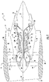
- FIG. 1 illustrates an exemplary gas turbine engine 10 (high bypass type) according to one embodiment of the present disclosure.
- the illustrated gas turbine engine 10 has an axial longitudinal centerline axis 12 therethrough for reference purposes.
- the gas turbine engine 10 preferably includes a core gas turbine engine generally identified by numeral 14 and a fan section 16 positioned upstream thereof.
- the core engine 14 typically includes a generally tubular outer casing 18 that defines an annular inlet 20.
- the outer casing 18 further encloses and supports a booster 22 for raising the pressure of the air that enters core engine 14 to a first pressure level.
- a high pressure, multi-stage, axial-flow compressor 24 receives pressurized air from the booster 22 and further increases the pressure of the air.
- the pressurized air flows to a combustor 26, where fuel is injected into the pressurized air stream and ignited to raise the temperature and energy level of the pressurized air.
- the high energy combustion products flow from the combustor 26 to a first (high pressure) turbine 28 for driving the high pressure compressor 24 through a first (high pressure) drive shaft 30, and then to a second (low pressure) turbine 32 for driving the booster 22 and the fan section 16 through a second (low pressure) drive shaft 34 that is coaxial with the first drive shaft 30.
- the combustion products leave the core engine 14 through an exhaust nozzle 36 to provide at least a portion of the jet propulsive thrust of the engine 10.
- the fan section 16 includes a rotatable, axial-flow fan rotor 38 that is surrounded by an annular fan casing 40.
- fan casing 40 is supported from the core engine 14 by a plurality of substantially radially-extending, circumferentially-spaced outlet guide vanes 42. In this way, the fan casing 40 encloses the fan rotor 38 and the fan rotor blades 44.
- the downstream section 46 of the fan casing 40 extends over an outer portion of the core engine 14 to define a secondary, or bypass, airflow conduit 48 that provides additional jet propulsive thrust.
- an initial airflow enters the gas turbine engine 10 through an inlet 52 to the fan casing 40.
- the airflow passes through the fan blades 44 and splits into a first air flow (represented by arrow 54) that moves through the conduit 48 and a second air flow (represented by arrow 56) which enters the booster 22.
- the pressure of the second airflow 56 is increased and enters the high pressure compressor 24, as represented by arrow 58. After mixing with fuel and being combusted in the combustor 26, the combustion products 60 exit the combustor 26 and flow through the first turbine 28. The combustion products 60 then flow through the second turbine 32 and exit the exhaust nozzle 36 to provide at least a portion of the thrust for the gas turbine engine 10.
- the combustor 26 includes an annular combustion chamber 62 that is coaxial with longitudinal centerline axis 12, as well as an inlet 64 and an outlet 66. As noted above, the combustor 26 receives an annular stream of pressurized air from a high pressure compressor discharge outlet 69. A portion of this compressor discharge air (“CDP" air) flows into a mixer (not shown). Fuel is injected from a fuel nozzle 100 to mix with the air and form a fuel-air mixture that is provided to the combustion chamber 62 for combustion. Ignition of the fuel-air mixture is accomplished by a suitable igniter, and the resulting combustion gases 60 flow in an axial direction toward and into an annular, first stage turbine nozzle 72.
- CDP compressor discharge air
- the nozzle 72 is defined by an annular flow channel that includes a plurality of radially-extending, circumferentially-spaced nozzle vanes 74 that turn the gases so that they flow angularly and impinge upon the first stage turbine blades of the first turbine 28.
- the first turbine 28 preferably rotates the high-pressure compressor 24 via the first drive shaft 30.
- the low-pressure turbine 32 preferably drives the booster 24 and the fan rotor 38 via the second drive shaft 34.
- the combustion chamber 62 is housed within engine outer casing 18. Fuel is supplied into the combustion chamber by one or more fuel nozzles. Liquid fuel is transported through conduits or passageways within a stem of each fuel nozzle. Further, the gas turbine engine 10 may use natural gas, various types of syngas, and/or other types of fuels. Moreover, the gas turbine engine 10 may have different configurations and may use other types of components in addition to those components shown. Multiple gas turbine engines, other types of turbines, and other types of power generation equipment also may be used herein together.
- the gas turbine engine assembly 100 generally includes a compressor 102, a combustion chamber 104, a high-pressure turbine 106 and a high-pressure shaft 110, a low-pressure turbine 108 and a low-pressure shaft 112, and various other optional components.
- the gas turbine engine assembly 100 may also include a generator 114 or a similar type of load.
- the generator 114 may be any type of device for the generation of electrical power. More specifically, as shown in FIG. 5 , the generator 114 may include a generator rotor 113 that rotates within a generator stator 115.
- rotation of the rotor 113 is due to the interaction13 between the windings and/or magnetic fields of the generator 114 which produces a torque around the rotor's axis.
- the generator 114 may be driven by the turbines 106, 108 via the shafts 110, 112.
- Other components and other configurations may also be used according to the present disclosure.
- the gas turbine engine assembly 100 may also include a power converter 122 having one or electrical circuits 127.
- the power converter 122 may include any suitable power converter.
- the power converter 122 generally includes circuitry for converting a variable frequency AC voltage from the generator 114 into a voltage that is supplied to power grid (not shown). Specifically, the power converter 122 is selectively activated to produce an output voltage, which is the AC voltage supplied to power grid.
- the power converter 122 may include various power switching devices such as, for example, insulated gate bipolar transistors (IGBTs), integrated gate-commutated thyristors (IGCTs), or any other suitable switching devices.
- IGBTs insulated gate bipolar transistors
- IGCTs integrated gate-commutated thyristors
- the gas turbine engine assembly 100 also may include a torsional damper 116 configured to dampen torsional oscillations of the generator 114 and/or a controller 120 configured to provide additional damping control to the engine 10.
- the torsional damper 116 is configured to reduce the oscillating torque between the generator 114 and the turbine 106, 108.
- the torsional damper 116 may be a mechanical damper 117.
- the mechanical damper 117 may be positioned circumferentially around the shaft 118, which operatively couples the low-pressure turbine 108 to the generator 114.
- the mechanical damper 117 may be configured at the front end of the generator 114.
- the mechanical damper 117 may be configured at the rear end of the generator 114.
- the mechanical damper 117 may be separate from the generator 114 ( FIG. 2 ) or integral with the generator 114 ( FIG. 5 ). Further, as shown in FIG.
- the torsional damper 116 and the generator 114 may be mechanically connected to the low-pressure shaft system (i.e. the fan, booster, and/or low-pressure turbine 108).
- the torsional damper 116 and the generator 114 may be mechanically connected to the high-pressure shaft system (i.e. the compressor 102 and/or the high-pressure turbine 106).
- the torsional damper 116 may be connected to any other shaft system.
- the mechanical damper 117 may be any suitable mechanical damper now known or later developed in the art.
- the mechanical damper 117 may include a viscous damper.
- a viscous damper generally refers to a mechanical device, which resists motion via viscous friction. The resulting force is substantially proportional to the oscillating velocity, but acts in the opposite direction, thereby decreasing the oscillation and absorbing energy without resulting in steady state losses.
- the torsional damper 116 of the present invention includes an electrical damper 124. More specifically, as shown, the electrical damper 124 is integrated into the power converter 122 of the assembly 100.
- the electrical damper 124 includes one or more resistors 125 integrated into one of the electrical circuits 127 of the power converter 122.
- the controller 120 is also configured to control the resistor 125 so as to prohibit the generator 114 from having a constant power load, thereby providing torsional damping thereof. Accordingly, the electrical damper 124 is configured to provide damping for forced excitations introduced to the assembly 100.
- the gas turbine engine assembly 100 may include a power bus damper component 126 configured to prohibit the generator 114 from having a constant power load.
- the power bus damper component 126 may include at least one of an active load 128, a controlled resistive load 130, a bus damper 132, or an energy storage device 134 (e.g. a battery, capacitor, or similar).
- the power bus damper component(s) 126 is configured to receive a speed and/or torque signal 136 from the generator 114 or the controller 120. Based on the signal 136, the bus damper component 126 is configured to prevent the bus from having a constant power load separated from voltage control.
- the power factor can be rcduccd to increase generator losses at the required mechanical damping frequencies. Such operation does not result in steady state losses, but rather only losses required to damp torsional oscillations.
- the controller 120 is configured to control a power factor of the generator 114 so as to provide torsional damping of the generator 114, e.g. by decreasing the power factor and creating losses internal to windings of the generator 114 and connecting cables.
- FIG. 10 it should be understood that the advantages described above may also be suitable for additional power systems, in addition to the gas turbine engine 10 of an aircraft power system as described herein.
- additional electrical power systems that may utilize the torsional damping features of the present disclosure may include gas turbine engines, wind turbines, steam turbines, or any other suitable generator-driven system.
- FIG. 10 a schematic diagram of an electrical power system 150 having improved torsional damping according to the present disclosure is illustrated. More specifically, as shown, the electrical power system 150 includes a first inertia system 152 connected to a second inertia system 154 via a shaft 156.
- the first inertia system 152 is larger than the second inertia system 154.
- the first inertia system 152 may be a generator
- the second inertia system 154 may include a generator driver, including but not limited to a low-pressure shaft system, a high-pressure shaft system, an intermediate shaft system, one or more rotor blades (optionally coupled to a gearbox), or any other suitable generator-driving component.
- the electrical power system 150 may include a torsional damper 158 configured to dampen torsional oscillations between the first and second inertia systems 152, 154.
- the second inertia system 154 may have a negative ratio of delta torque and delta speed, i.e. may have negative damping.
- the torsional damper 158 may be configured to correct the negative damping of the second inertia system 154.
- the torsional damper 158 may be configured to provide damping for forced excitations introduced to the systems 152, 154.
- the electrical power system 150 includes a controller 160 configured to provide additional damping control for the first and second inertia systems 152, 154.
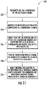
- FIG. 11 a flow diagram of one embodiment of a method 200 of operating a gas turbine engine.
- the method 200 includes pressurizing air via a compressor 24 of the gas turbine engine 10.
- the method 200 includes providing the pressurized air to a combustion chamber 62 from the compressor 24.
- the method 200 includes injecting fuel into pressurized air within the combustion chamber 62 and igniting the fuel so as to raise a temperature and energy level of the pressurized air.
- the method 200 includes providing combustion products from the combustion chamber 62 to the turbine (e.g. turbines 106, 108) coupled to a generator 114. As shown at 210, the method 200 also includes damping torsional oscillations of the generator 114 via a torsional damper 116 and additional damping provided by a generator controller 120.
- the turbine e.g. turbines 106, 108
- the method 200 also includes damping torsional oscillations of the generator 114 via a torsional damper 116 and additional damping provided by a generator controller 120.
- the step of damping torsional oscillations of the generator 114 via the torsional damper 116 includes providing an electrical damper 124.
- the method 200 includes integrating the electrical damper 124 into the power converter 122. More specifically, as mentioned, the electrical damper 124 includes a resistor 125. Thus the method 200 includes controlling, via the controller 120, the resistor 125 so as to prohibit the generator 114 from having a constant power load at frequencies of torsional interaction.
- the method 200 may include operatively coupling a power bus damper 126 with the power converter 122 and/or the controller 120.
- the power bus damper 126 is configured to prohibit the generator 114 from having a constant power load.
- the power bus damper 126 may include an active load 128, a controlled resistive load 130, a bus damper 132, an energy storage device 134, or similar, or combinations thereof.
- the method 200 may include controlling a power factor of the generator 114 so as to provide torsional damping of the generator 114, e.g. by decreasing the power factor and creating losses internal to windings of the generator 114 or connecting cables.
- the torsional damper 160 may be used with any type of turbo-machinery and the like.
- the combination of any or all of the damping components and/or features described herein can be used to provide positive generator damping, e.g. at specific frequencies, wide frequency ranges, and may be adjustable.
- This written description uses examples to disclose the invention, including the best mode, and also to enable any person skilled in the art to practice the invention, including making and using any devices or systems and performing any incorporated methods.
- the patentable scope of the invention is defined by the claims, and may include other examples that occur to those skilled in the art. Such other examples are intended to be within the scope of the claims if they include structural elements that do not differ from the literal language of the claims.
Landscapes
- Engineering & Computer Science (AREA)
- General Engineering & Computer Science (AREA)
- Mechanical Engineering (AREA)
- Chemical & Material Sciences (AREA)
- Combustion & Propulsion (AREA)
- Physics & Mathematics (AREA)
- Acoustics & Sound (AREA)
- Aviation & Aerospace Engineering (AREA)
- Power Engineering (AREA)
- Control Of Eletrric Generators (AREA)
- Connection Of Motors, Electrical Generators, Mechanical Devices, And The Like (AREA)
Claims (4)
- Gasturbinentriebwerksanordnung, umfassend:einen Kompressor (24), der konfiguriert ist, um einen Druck von eingehender Luft zu erhöhen;eine Brennkammer (104), die konfiguriert ist, um einen Druckluftstrom von dem Kompressor (24) aufzunehmen, wobei Kraftstoff in den Druckluftstrom eingespritzt und gezündet wird, um eine Temperatur und ein Energieniveau der Druckluft zu erhöhen;eine Turbine (106, 108), die mit der Brennkammer (104) wirkgekoppelt ist, um Verbrennungsprodukte aufzunehmen, die aus der Brennkammer (104) strömen;einen Generator (114), der mit einem Wellensystem (110, 112) der Turbine (106, 108) über eine Welle (118) gekoppelt ist;einen elektrischen Torsionsdämpfer (116, 124), der in einen Leistungswandler (122) des Generators integriert und konfiguriert ist, um Torsionsschwingungen des Wellensystems (110, 112) des Generators (114) zu dämpfen;wobei der Leistungswandler (122) einen oder mehrere elektrische Schaltkreise (117) umfasst, wobei der elektrische Dämpfer (116, 124) einen Widerstand (125) umfasst, der in einen der elektrischen Schaltkreise (117) des Leistungswandlers (122) integriert ist; undeine Steuerung (120), die konfiguriert ist, um dem Generator (114) eine zusätzliche Dämpfungssteuerung bereitzustellen, durch Verringern eines Leistungsfaktors und Erzeugen von Verlusten im Inneren an Wicklungen des Generators (114), wobei die Steuerung (120) ferner konfiguriert ist, um den Widerstand (125) zu steuern, um zu verhindern, dass der Generator (114) eine konstante Leistungslast bei Frequenzen einer Torsionswechselwirkung aufweist.
- Gasturbinentriebwerksanordnung nach Anspruch 1, ferner umfassend einen Leistungsbusdämpfer (126), der konfiguriert ist, um zu verhindern, dass der Generator (114) eine konstante Leistungslast bei Frequenzen einer Torsionswechselwirkung aufweist.
- Gasturbinentriebwerksanordnung nach Anspruch 2, wobei der Leistungsbusdämpfer (126) mindestens eines von einer aktiven Last (128), einer gesteuerten Widerstandslast (130) oder einer Energiespeichervorrichtung (134) umfasst.
- Verfahren (200) zum Betreiben einer Gasturbinentriebwerksanordnung, umfassend:Unterdrucksetzen von Luft über einen Kompressor (24) der Gasturbinentriebwerksanordnung;Bereitstellen der Druckluft von dem Kompressor (24) an eine Brennkammer (104);Einspritzen von Kraftstoff in die Druckluft innerhalb der Brennkammer (104) und Zünden des Kraftstoffs, um eine Temperatur und ein Energieniveau der Druckluft zu erhöhen;Bereitstellen von Verbrennungsprodukten von der Brennkammer (104) an eine Turbine, die mit einem Generator (114) gekoppelt ist;Dämpfen von Torsionsschwingungen eines Wellensystems des Generators (114) über einen elektrischen Torsionsdämpfer (116, 124) und eine zusätzliche Dämpfungssteuerung, die durch die Steuerung (120) des Generators (114) bereitgestellt wird; undSteuern, über die Steuerung (120), eines Leistungsfaktors des Generators, um eine zusätzliche Torsionsdämpfung des Generators (114) bereitzustellen, durch Erzeugen von Verlusten im Inneren an dem Generator (114);wobei der elektrische Torsionsdämpfer einen Widerstand (125) beinhaltet, der in einen elektrischen Schaltkreis (117) integriert ist, und die Steuerung (120) konfiguriert ist, den Widerstand (125) zu steuern, um zu verhindern, dass der Generator (114) eine konstante Leistungslast bei Frequenzen einer Torsionswechselwirkung aufweist,wobei das Verfahren ferner ein Integrieren des elektrischen Dämpfers (116, 124) in einen Leistungswandler (122) des Generators (114) umfasst, undSteuern, über die Steuerung (120), des Widerstands (125), um zu verhindern, dass der Generator (114) eine konstante Leistungslast bei Frequenzen einer Torsionswechselwirkung aufweist.
Applications Claiming Priority (2)
| Application Number | Priority Date | Filing Date | Title |
|---|---|---|---|
| US14/920,993 US20170114664A1 (en) | 2015-10-23 | 2015-10-23 | Torsional damping for gas turbine engines |
| US15/018,966 US9938853B2 (en) | 2015-10-23 | 2016-02-09 | Torsional damping for gas turbine engines |
Publications (2)
| Publication Number | Publication Date |
|---|---|
| EP3159573A1 EP3159573A1 (de) | 2017-04-26 |
| EP3159573B1 true EP3159573B1 (de) | 2022-07-27 |
Family
ID=57178327
Family Applications (1)
| Application Number | Title | Priority Date | Filing Date |
|---|---|---|---|
| EP16194769.2A Active EP3159573B1 (de) | 2015-10-23 | 2016-10-20 | Torsionsdämpfung für gasturbinenmotoren |
Country Status (6)
| Country | Link |
|---|---|
| US (1) | US9938853B2 (de) |
| EP (1) | EP3159573B1 (de) |
| JP (1) | JP6438926B2 (de) |
| CN (1) | CN107013330B (de) |
| BR (1) | BR102016024577A2 (de) |
| CA (1) | CA2945248C (de) |
Families Citing this family (14)
| Publication number | Priority date | Publication date | Assignee | Title |
|---|---|---|---|---|
| US10731501B2 (en) * | 2016-04-22 | 2020-08-04 | Hamilton Sundstrand Corporation | Environmental control system utilizing a motor assist and an enhanced compressor |
| US10693403B2 (en) * | 2017-03-23 | 2020-06-23 | Ge Aviation Systems Llc | Torsional damping for generators |
| US10256638B2 (en) | 2017-08-24 | 2019-04-09 | Ge Aviation Systems Llc | Method and system for operating a set of generators |
| US10644630B2 (en) | 2017-11-28 | 2020-05-05 | General Electric Company | Turbomachine with an electric machine assembly and method for operation |
| CN109139796B (zh) * | 2018-10-22 | 2023-08-29 | 沈阳航空航天大学 | 一种固定端封式挤压油膜阻尼器 |
| GB201818268D0 (en) * | 2018-11-09 | 2018-12-26 | Rolls Royce | Shaft resonance control |
| EP3683471B1 (de) | 2019-01-15 | 2024-03-06 | ABB Schweiz AG | Dämpfung von torsionsschwingungen in einem antriebssystem |
| US11539316B2 (en) | 2019-07-30 | 2022-12-27 | General Electric Company | Active stability control of compression systems utilizing electric machines |
| US11671038B2 (en) * | 2019-08-09 | 2023-06-06 | Hamilton Sundstrand Corporation | Control of a wound field synchronous generator for transient load response |
| GB201915310D0 (en) * | 2019-10-23 | 2019-12-04 | Rolls Royce Plc | Turboelectric generator system |
| JP2022015892A (ja) * | 2020-07-10 | 2022-01-21 | 東芝エネルギーシステムズ株式会社 | タービン発電システム |
| CN112361423B (zh) * | 2020-10-30 | 2022-08-23 | 广西电网有限责任公司电力科学研究院 | 一种热电联产机组低压汽源升压供热装置 |
| US12480449B2 (en) | 2022-08-22 | 2025-11-25 | General Electric Company | Propulsion system including an electric machine for starting a gas turbine engine |
| US12215630B2 (en) | 2022-12-23 | 2025-02-04 | Pratt & Whitney Canada Corp. | Flex coupler for hybrid gas turbine engine powerplant |
Citations (1)
| Publication number | Priority date | Publication date | Assignee | Title |
|---|---|---|---|---|
| EP2264867A1 (de) * | 2009-06-17 | 2010-12-22 | Hamilton Sundstrand Corporation | Verschachtelter Torsionsdämpfer für eine elektrische Maschine |
Family Cites Families (71)
| Publication number | Priority date | Publication date | Assignee | Title |
|---|---|---|---|---|
| US3598211A (en) * | 1968-09-30 | 1971-08-10 | Eaton Yale & Towne | Speed-responsive clutch |
| US3999115A (en) * | 1974-05-02 | 1976-12-21 | Westinghouse Electric Corporation | Dynamic stabilizer for synchronous machines having torsional oscillations and method |
| US4114246A (en) * | 1977-06-29 | 1978-09-19 | Houdaille Industries, Inc. | Method of and means for making tuned viscous torsional vibration dampers |
| US4311253A (en) * | 1979-09-14 | 1982-01-19 | Westinghouse Electric Corp. | Low loss stabilizer |
| US4370560A (en) | 1979-10-15 | 1983-01-25 | Sundstrand Corporation | Compressor load control for an auxiliary power unit |
| JPH0730812B2 (ja) * | 1987-01-28 | 1995-04-10 | 三信工業株式会社 | 動力伝達装置 |
| US5174109A (en) | 1990-10-25 | 1992-12-29 | Sundstrand Corporation | Clutch to disconnect loads during turbine start-up |
| US6105697A (en) | 1996-04-01 | 2000-08-22 | Weaver; Winstead B. | Hybrid turbine-electric motor system |
| US5799484A (en) | 1997-04-15 | 1998-09-01 | Allied Signal Inc | Dual turbogenerator auxiliary power system |
| CA2318944C (en) | 1997-12-20 | 2007-09-11 | Alliedsignal Inc. | Constant turbine inlet temperature control of a microturbine power generating system |
| US6992403B1 (en) | 2001-03-08 | 2006-01-31 | Pacific Scientific | Electric power and start system |
| US6545373B1 (en) | 2001-08-24 | 2003-04-08 | Smiths Aerospace, Inc. | System and method for providing ballast loading for a turbo-generator |
| GB0120748D0 (en) * | 2001-08-25 | 2001-10-17 | Lucas Aerospace Power Equip | Generator |
| US6834831B2 (en) | 2002-12-31 | 2004-12-28 | The Boeing Company | Hybrid solid oxide fuel cell aircraft auxiliary power unit |
| US8631657B2 (en) | 2003-01-22 | 2014-01-21 | Vast Power Portfolio, Llc | Thermodynamic cycles with thermal diluent |
| US7417337B1 (en) | 2003-09-04 | 2008-08-26 | Hamilton Sundstrand Corporation | Method and system for facilitating no-break power transfer |
| DE10359559A1 (de) | 2003-12-18 | 2005-07-28 | Mtu Aero Engines Gmbh | Gasturbine, insbesondere Flugtriebwerk |
| US7251942B2 (en) | 2004-06-29 | 2007-08-07 | Honeywell International Inc. | Integrated gearless and nonlubricated auxiliary power unit |
| US7285871B2 (en) | 2004-08-25 | 2007-10-23 | Honeywell International, Inc. | Engine power extraction control system |
| US7173399B2 (en) * | 2005-04-19 | 2007-02-06 | General Electric Company | Integrated torsional mode damping system and method |
| US7380749B2 (en) | 2005-04-21 | 2008-06-03 | The Boeing Company | Combined fuel cell aircraft auxiliary power unit and environmental control system |
| US7677502B2 (en) | 2005-09-29 | 2010-03-16 | The Boeing Company | Method and apparatus for generating lift |
| US8141360B1 (en) | 2005-10-18 | 2012-03-27 | Florida Turbine Technologies, Inc. | Hybrid gas turbine and internal combustion engine |
| US7372174B2 (en) * | 2005-11-11 | 2008-05-13 | Converteam Ltd | Power converters |
| US7958727B2 (en) | 2005-12-29 | 2011-06-14 | Honeywell International Inc. | Electric boost compressor and turbine generator system |
| US7423411B2 (en) * | 2006-05-05 | 2008-09-09 | General Electric Company | Resistive torsional mode damping system and method |
| US7970497B2 (en) | 2007-03-02 | 2011-06-28 | Honeywell International Inc. | Smart hybrid electric and bleed architecture |
| US8004252B2 (en) * | 2007-06-29 | 2011-08-23 | General Electric Company | Power system stabilizer and method |
| US8193761B1 (en) | 2007-11-08 | 2012-06-05 | Honeywell International, Inc. | Hybrid power source |
| WO2009091834A1 (en) | 2008-01-14 | 2009-07-23 | Internal Combustion Turbines Llc | Internal combustion engine driven turbogenerator for hybrid vehicles and power generation |
| US8039983B2 (en) | 2008-12-02 | 2011-10-18 | The Boeing Company | Systems and methods for providing AC power from multiple turbine engine spools |
| US8344673B2 (en) * | 2008-12-04 | 2013-01-01 | Nuovo Pignone S.P.A. | Torsional mode damping apparatus |
| EP2218939A1 (de) | 2009-02-11 | 2010-08-18 | Converteam Technology Ltd | Elektrische Drehmaschinen |
| US8167062B2 (en) | 2009-05-21 | 2012-05-01 | Tognum America Inc. | Power generation system and method for assembling the same |
| JP5486847B2 (ja) | 2009-06-02 | 2014-05-07 | 株式会社日立製作所 | 電力変換装置 |
| US8568938B2 (en) | 2009-08-28 | 2013-10-29 | The Boeing Company | Thermoelectric generator and fuel cell for electric power co-generation |
| US8657227B1 (en) | 2009-09-11 | 2014-02-25 | The Boeing Company | Independent power generation in aircraft |
| US8217630B2 (en) * | 2009-11-18 | 2012-07-10 | Hamilton Sundstrand Corporation | Electric load damper for damping torsional oscillation |
| US7818969B1 (en) | 2009-12-18 | 2010-10-26 | Energyield, Llc | Enhanced efficiency turbine |
| US8415914B2 (en) | 2010-01-13 | 2013-04-09 | Hamilton Sundstrand Corporation | Motor drive load damping |
| US8489246B2 (en) | 2010-02-26 | 2013-07-16 | Pratt & Whitney Canada Corp. | Hybrid control system |
| IT1399116B1 (it) | 2010-04-01 | 2013-04-05 | Nuovo Pignone Spa | Sistema e metodo di smorzamento del modo torsionale basato su raddrizzatore e invertitore |
| FR2958689B1 (fr) | 2010-04-12 | 2012-04-20 | Aircelle Sa | Systeme de commande d'un dispositif electrique d'une nacelle |
| US8522522B2 (en) | 2010-07-30 | 2013-09-03 | Hamilton Sundstrand Corporation | Fan embedded power generator |
| US8836160B1 (en) | 2010-09-28 | 2014-09-16 | The Boeing Company | Method and application for vehicle power system isolation |
| US20120214605A1 (en) | 2011-02-21 | 2012-08-23 | General Electric Company | Gas Turbine Engine Generator System with Torsional Damping Coupling |
| US8432048B1 (en) | 2011-03-08 | 2013-04-30 | Florida Turbine Technologies, Inc. | Hybrid engine with a gas turbine engine |
| FR2975547B1 (fr) | 2011-05-20 | 2013-06-07 | Turbomeca | Procede de rationalisation de chaine de composants electriques d'un aeronef, architecture de mise en oeuvre et aeronef correspondant |
| US9540998B2 (en) | 2011-05-27 | 2017-01-10 | Daniel K. Schlak | Integral gas turbine, flywheel, generator, and method for hybrid operation thereof |
| US8928166B2 (en) | 2011-08-31 | 2015-01-06 | Hamilton Sundstrand Corporation | Mixed mode power generation architecture |
| FR2990414B1 (fr) | 2012-05-10 | 2015-04-10 | Microturbo | Procede de fourniture de puissance auxiliaire par un groupe auxiliaire de puissance et architecture correspondante |
| DE102012209803A1 (de) | 2012-06-12 | 2013-12-12 | Siemens Aktiengesellschaft | Verfahren zum Bereitstellen einer vorbestimmten Antriebscharakteristik in einem Flugzeug und zugehörige Antriebsvorrichtung |
| US9068562B1 (en) | 2012-10-05 | 2015-06-30 | The Boeing Company | Laser-powered propulsion system |
| US8957539B1 (en) | 2012-10-16 | 2015-02-17 | The Boeing Company | Hybrid turbogenerator and associated method |
| GB201219916D0 (en) | 2012-11-06 | 2012-12-19 | Rolls Royce Plc | An electrical generation arrangement for an aircraft |
| US9045996B2 (en) | 2012-11-20 | 2015-06-02 | Honeywell International Inc. | Gas turbine engine optimization by electric power transfer |
| US8742605B1 (en) | 2013-02-07 | 2014-06-03 | Hamilton Sundstrand Corporation | Method for aircraft engine start using synchronous generator and constant speed drive |
| US8997493B2 (en) | 2013-02-20 | 2015-04-07 | Hamilton Sunstrand Corporation | Auxiliary power unit generator |
| WO2014143219A1 (en) | 2013-03-13 | 2014-09-18 | Phillips Steven D | Engine health monitoring and power allocation control for a turbine engine using electric generators |
| CA2905233C (en) | 2013-03-14 | 2022-04-26 | Rolls-Royce Corporation | Intelligent integrated control system and method |
| US9318991B2 (en) | 2013-04-11 | 2016-04-19 | The Boeing Company | Electric motor frequency modulation system |
| US9130494B2 (en) | 2013-09-26 | 2015-09-08 | The Boeing Company | Electric motor phase control system |
| FR3011144B1 (fr) | 2013-09-26 | 2018-06-15 | Dassault Aviation | Procede et module de protection contre les pics de couple entre moteur et une machine electrique |
| US9452721B2 (en) | 2013-10-02 | 2016-09-27 | The Boeing Company | Systems, methods, and apparatus for an emergency power generator |
| US9428263B2 (en) | 2013-10-16 | 2016-08-30 | The Boeing Company | Frequency response and health tracker for a synthetic jet generator |
| US10113487B2 (en) | 2013-10-24 | 2018-10-30 | United Technologies Corporation | Cascaded multi-variable control system for a turboshaft engine |
| US11267574B2 (en) | 2013-10-28 | 2022-03-08 | The Boeing Company | Aircraft with electric motor and rechargeable power source |
| US9815564B2 (en) | 2013-12-04 | 2017-11-14 | The Boeing Company | Non-propulsive utility power (NPUP) generation system for providing full-time secondary power during operation of an aircraft |
| US9366182B2 (en) | 2013-12-06 | 2016-06-14 | Rolls-Royce Corporation | Integrated electrical power and thermal management system |
| US9771163B2 (en) | 2013-12-31 | 2017-09-26 | The Boeing Company | Short takeoff and landing aircraft |
| US20170114664A1 (en) | 2015-10-23 | 2017-04-27 | General Electric Company | Torsional damping for gas turbine engines |
-
2016
- 2016-02-09 US US15/018,966 patent/US9938853B2/en active Active
- 2016-10-07 JP JP2016198602A patent/JP6438926B2/ja not_active Expired - Fee Related
- 2016-10-13 CA CA2945248A patent/CA2945248C/en active Active
- 2016-10-20 EP EP16194769.2A patent/EP3159573B1/de active Active
- 2016-10-20 CN CN201610913787.XA patent/CN107013330B/zh active Active
- 2016-10-21 BR BR102016024577-0A patent/BR102016024577A2/pt not_active IP Right Cessation
Patent Citations (1)
| Publication number | Priority date | Publication date | Assignee | Title |
|---|---|---|---|---|
| EP2264867A1 (de) * | 2009-06-17 | 2010-12-22 | Hamilton Sundstrand Corporation | Verschachtelter Torsionsdämpfer für eine elektrische Maschine |
Also Published As
| Publication number | Publication date |
|---|---|
| CN107013330A (zh) | 2017-08-04 |
| EP3159573A1 (de) | 2017-04-26 |
| US9938853B2 (en) | 2018-04-10 |
| CA2945248A1 (en) | 2017-04-23 |
| JP6438926B2 (ja) | 2018-12-19 |
| CN107013330B (zh) | 2019-07-16 |
| BR102016024577A2 (pt) | 2017-07-18 |
| CA2945248C (en) | 2019-07-02 |
| JP2017096258A (ja) | 2017-06-01 |
| US20170114665A1 (en) | 2017-04-27 |
Similar Documents
| Publication | Publication Date | Title |
|---|---|---|
| EP3159573B1 (de) | Torsionsdämpfung für gasturbinenmotoren | |
| US12372006B2 (en) | Torsional damping for gas turbine engines | |
| US12571360B2 (en) | Three-stream gas turbine engine with embedded electric machine | |
| US11067003B2 (en) | Fluid cooling structure for an electric machine of a gas turbine engine | |
| US8314505B2 (en) | Gas turbine engine apparatus | |
| CN109028142B (zh) | 推进系统及操作其的方法 | |
| US11970947B2 (en) | Power generation system | |
| US20230121431A1 (en) | Gas turbine propulsion system | |
| US20240426239A1 (en) | Method of generating power with an electric machine | |
| US12331702B2 (en) | Turboshaft engine | |
| CA3174071C (en) | A power generaton system |
Legal Events
| Date | Code | Title | Description |
|---|---|---|---|
| PUAI | Public reference made under article 153(3) epc to a published international application that has entered the european phase |
Free format text: ORIGINAL CODE: 0009012 |
|
| STAA | Information on the status of an ep patent application or granted ep patent |
Free format text: STATUS: THE APPLICATION HAS BEEN PUBLISHED |
|
| AK | Designated contracting states |
Kind code of ref document: A1 Designated state(s): AL AT BE BG CH CY CZ DE DK EE ES FI FR GB GR HR HU IE IS IT LI LT LU LV MC MK MT NL NO PL PT RO RS SE SI SK SM TR |
|
| AX | Request for extension of the european patent |
Extension state: BA ME |
|
| STAA | Information on the status of an ep patent application or granted ep patent |
Free format text: STATUS: REQUEST FOR EXAMINATION WAS MADE |
|
| 17P | Request for examination filed |
Effective date: 20171026 |
|
| RBV | Designated contracting states (corrected) |
Designated state(s): AL AT BE BG CH CY CZ DE DK EE ES FI FR GB GR HR HU IE IS IT LI LT LU LV MC MK MT NL NO PL PT RO RS SE SI SK SM TR |
|
| STAA | Information on the status of an ep patent application or granted ep patent |
Free format text: STATUS: EXAMINATION IS IN PROGRESS |
|
| 17Q | First examination report despatched |
Effective date: 20190708 |
|
| GRAP | Despatch of communication of intention to grant a patent |
Free format text: ORIGINAL CODE: EPIDOSNIGR1 |
|
| STAA | Information on the status of an ep patent application or granted ep patent |
Free format text: STATUS: GRANT OF PATENT IS INTENDED |
|
| INTG | Intention to grant announced |
Effective date: 20220214 |
|
| RIN1 | Information on inventor provided before grant (corrected) |
Inventor name: STEEN, TOD ROBERT Inventor name: BECKER, THOMAS LEE Inventor name: GEMIN, PAUL ROBERT |
|
| GRAS | Grant fee paid |
Free format text: ORIGINAL CODE: EPIDOSNIGR3 |
|
| GRAA | (expected) grant |
Free format text: ORIGINAL CODE: 0009210 |
|
| STAA | Information on the status of an ep patent application or granted ep patent |
Free format text: STATUS: THE PATENT HAS BEEN GRANTED |
|
| AK | Designated contracting states |
Kind code of ref document: B1 Designated state(s): AL AT BE BG CH CY CZ DE DK EE ES FI FR GB GR HR HU IE IS IT LI LT LU LV MC MK MT NL NO PL PT RO RS SE SI SK SM TR |
|
| REG | Reference to a national code |
Ref country code: CH Ref legal event code: EP |
|
| REG | Reference to a national code |
Ref country code: DE Ref legal event code: R096 Ref document number: 602016073748 Country of ref document: DE |
|
| REG | Reference to a national code |
Ref country code: AT Ref legal event code: REF Ref document number: 1507257 Country of ref document: AT Kind code of ref document: T Effective date: 20220815 |
|
| REG | Reference to a national code |
Ref country code: IE Ref legal event code: FG4D |
|
| REG | Reference to a national code |
Ref country code: LT Ref legal event code: MG9D |
|
| REG | Reference to a national code |
Ref country code: NL Ref legal event code: MP Effective date: 20220727 |
|
| PG25 | Lapsed in a contracting state [announced via postgrant information from national office to epo] |
Ref country code: SE Free format text: LAPSE BECAUSE OF FAILURE TO SUBMIT A TRANSLATION OF THE DESCRIPTION OR TO PAY THE FEE WITHIN THE PRESCRIBED TIME-LIMIT Effective date: 20220727 Ref country code: RS Free format text: LAPSE BECAUSE OF FAILURE TO SUBMIT A TRANSLATION OF THE DESCRIPTION OR TO PAY THE FEE WITHIN THE PRESCRIBED TIME-LIMIT Effective date: 20220727 Ref country code: PT Free format text: LAPSE BECAUSE OF FAILURE TO SUBMIT A TRANSLATION OF THE DESCRIPTION OR TO PAY THE FEE WITHIN THE PRESCRIBED TIME-LIMIT Effective date: 20221128 Ref country code: NO Free format text: LAPSE BECAUSE OF FAILURE TO SUBMIT A TRANSLATION OF THE DESCRIPTION OR TO PAY THE FEE WITHIN THE PRESCRIBED TIME-LIMIT Effective date: 20221027 Ref country code: NL Free format text: LAPSE BECAUSE OF FAILURE TO SUBMIT A TRANSLATION OF THE DESCRIPTION OR TO PAY THE FEE WITHIN THE PRESCRIBED TIME-LIMIT Effective date: 20220727 Ref country code: LV Free format text: LAPSE BECAUSE OF FAILURE TO SUBMIT A TRANSLATION OF THE DESCRIPTION OR TO PAY THE FEE WITHIN THE PRESCRIBED TIME-LIMIT Effective date: 20220727 Ref country code: LT Free format text: LAPSE BECAUSE OF FAILURE TO SUBMIT A TRANSLATION OF THE DESCRIPTION OR TO PAY THE FEE WITHIN THE PRESCRIBED TIME-LIMIT Effective date: 20220727 Ref country code: FI Free format text: LAPSE BECAUSE OF FAILURE TO SUBMIT A TRANSLATION OF THE DESCRIPTION OR TO PAY THE FEE WITHIN THE PRESCRIBED TIME-LIMIT Effective date: 20220727 Ref country code: ES Free format text: LAPSE BECAUSE OF FAILURE TO SUBMIT A TRANSLATION OF THE DESCRIPTION OR TO PAY THE FEE WITHIN THE PRESCRIBED TIME-LIMIT Effective date: 20220727 |
|
| REG | Reference to a national code |
Ref country code: AT Ref legal event code: MK05 Ref document number: 1507257 Country of ref document: AT Kind code of ref document: T Effective date: 20220727 |
|
| PG25 | Lapsed in a contracting state [announced via postgrant information from national office to epo] |
Ref country code: PL Free format text: LAPSE BECAUSE OF FAILURE TO SUBMIT A TRANSLATION OF THE DESCRIPTION OR TO PAY THE FEE WITHIN THE PRESCRIBED TIME-LIMIT Effective date: 20220727 Ref country code: IS Free format text: LAPSE BECAUSE OF FAILURE TO SUBMIT A TRANSLATION OF THE DESCRIPTION OR TO PAY THE FEE WITHIN THE PRESCRIBED TIME-LIMIT Effective date: 20221127 Ref country code: HR Free format text: LAPSE BECAUSE OF FAILURE TO SUBMIT A TRANSLATION OF THE DESCRIPTION OR TO PAY THE FEE WITHIN THE PRESCRIBED TIME-LIMIT Effective date: 20220727 Ref country code: GR Free format text: LAPSE BECAUSE OF FAILURE TO SUBMIT A TRANSLATION OF THE DESCRIPTION OR TO PAY THE FEE WITHIN THE PRESCRIBED TIME-LIMIT Effective date: 20221028 |
|
| PG25 | Lapsed in a contracting state [announced via postgrant information from national office to epo] |
Ref country code: SM Free format text: LAPSE BECAUSE OF FAILURE TO SUBMIT A TRANSLATION OF THE DESCRIPTION OR TO PAY THE FEE WITHIN THE PRESCRIBED TIME-LIMIT Effective date: 20220727 Ref country code: RO Free format text: LAPSE BECAUSE OF FAILURE TO SUBMIT A TRANSLATION OF THE DESCRIPTION OR TO PAY THE FEE WITHIN THE PRESCRIBED TIME-LIMIT Effective date: 20220727 Ref country code: DK Free format text: LAPSE BECAUSE OF FAILURE TO SUBMIT A TRANSLATION OF THE DESCRIPTION OR TO PAY THE FEE WITHIN THE PRESCRIBED TIME-LIMIT Effective date: 20220727 Ref country code: CZ Free format text: LAPSE BECAUSE OF FAILURE TO SUBMIT A TRANSLATION OF THE DESCRIPTION OR TO PAY THE FEE WITHIN THE PRESCRIBED TIME-LIMIT Effective date: 20220727 Ref country code: AT Free format text: LAPSE BECAUSE OF FAILURE TO SUBMIT A TRANSLATION OF THE DESCRIPTION OR TO PAY THE FEE WITHIN THE PRESCRIBED TIME-LIMIT Effective date: 20220727 |
|
| REG | Reference to a national code |
Ref country code: DE Ref legal event code: R097 Ref document number: 602016073748 Country of ref document: DE |
|
| PG25 | Lapsed in a contracting state [announced via postgrant information from national office to epo] |
Ref country code: SK Free format text: LAPSE BECAUSE OF FAILURE TO SUBMIT A TRANSLATION OF THE DESCRIPTION OR TO PAY THE FEE WITHIN THE PRESCRIBED TIME-LIMIT Effective date: 20220727 Ref country code: MC Free format text: LAPSE BECAUSE OF FAILURE TO SUBMIT A TRANSLATION OF THE DESCRIPTION OR TO PAY THE FEE WITHIN THE PRESCRIBED TIME-LIMIT Effective date: 20220727 Ref country code: EE Free format text: LAPSE BECAUSE OF FAILURE TO SUBMIT A TRANSLATION OF THE DESCRIPTION OR TO PAY THE FEE WITHIN THE PRESCRIBED TIME-LIMIT Effective date: 20220727 |
|
| REG | Reference to a national code |
Ref country code: CH Ref legal event code: PL |
|
| PLBE | No opposition filed within time limit |
Free format text: ORIGINAL CODE: 0009261 |
|
| STAA | Information on the status of an ep patent application or granted ep patent |
Free format text: STATUS: NO OPPOSITION FILED WITHIN TIME LIMIT |
|
| P01 | Opt-out of the competence of the unified patent court (upc) registered |
Effective date: 20230414 |
|
| REG | Reference to a national code |
Ref country code: BE Ref legal event code: MM Effective date: 20221031 |
|
| PG25 | Lapsed in a contracting state [announced via postgrant information from national office to epo] |
Ref country code: LU Free format text: LAPSE BECAUSE OF NON-PAYMENT OF DUE FEES Effective date: 20221020 Ref country code: AL Free format text: LAPSE BECAUSE OF FAILURE TO SUBMIT A TRANSLATION OF THE DESCRIPTION OR TO PAY THE FEE WITHIN THE PRESCRIBED TIME-LIMIT Effective date: 20220727 |
|
| 26N | No opposition filed |
Effective date: 20230502 |
|
| PG25 | Lapsed in a contracting state [announced via postgrant information from national office to epo] |
Ref country code: LI Free format text: LAPSE BECAUSE OF NON-PAYMENT OF DUE FEES Effective date: 20221031 Ref country code: CH Free format text: LAPSE BECAUSE OF NON-PAYMENT OF DUE FEES Effective date: 20221031 |
|
| PG25 | Lapsed in a contracting state [announced via postgrant information from national office to epo] |
Ref country code: SI Free format text: LAPSE BECAUSE OF FAILURE TO SUBMIT A TRANSLATION OF THE DESCRIPTION OR TO PAY THE FEE WITHIN THE PRESCRIBED TIME-LIMIT Effective date: 20220727 |
|
| PG25 | Lapsed in a contracting state [announced via postgrant information from national office to epo] |
Ref country code: BE Free format text: LAPSE BECAUSE OF NON-PAYMENT OF DUE FEES Effective date: 20221031 |
|
| PG25 | Lapsed in a contracting state [announced via postgrant information from national office to epo] |
Ref country code: IE Free format text: LAPSE BECAUSE OF NON-PAYMENT OF DUE FEES Effective date: 20221020 |
|
| PG25 | Lapsed in a contracting state [announced via postgrant information from national office to epo] |
Ref country code: HU Free format text: LAPSE BECAUSE OF FAILURE TO SUBMIT A TRANSLATION OF THE DESCRIPTION OR TO PAY THE FEE WITHIN THE PRESCRIBED TIME-LIMIT; INVALID AB INITIO Effective date: 20161020 |
|
| PG25 | Lapsed in a contracting state [announced via postgrant information from national office to epo] |
Ref country code: CY Free format text: LAPSE BECAUSE OF FAILURE TO SUBMIT A TRANSLATION OF THE DESCRIPTION OR TO PAY THE FEE WITHIN THE PRESCRIBED TIME-LIMIT Effective date: 20220727 |
|
| PG25 | Lapsed in a contracting state [announced via postgrant information from national office to epo] |
Ref country code: MK Free format text: LAPSE BECAUSE OF FAILURE TO SUBMIT A TRANSLATION OF THE DESCRIPTION OR TO PAY THE FEE WITHIN THE PRESCRIBED TIME-LIMIT Effective date: 20220727 Ref country code: IT Free format text: LAPSE BECAUSE OF FAILURE TO SUBMIT A TRANSLATION OF THE DESCRIPTION OR TO PAY THE FEE WITHIN THE PRESCRIBED TIME-LIMIT Effective date: 20220727 |
|
| PG25 | Lapsed in a contracting state [announced via postgrant information from national office to epo] |
Ref country code: TR Free format text: LAPSE BECAUSE OF FAILURE TO SUBMIT A TRANSLATION OF THE DESCRIPTION OR TO PAY THE FEE WITHIN THE PRESCRIBED TIME-LIMIT Effective date: 20220727 |
|
| PG25 | Lapsed in a contracting state [announced via postgrant information from national office to epo] |
Ref country code: BG Free format text: LAPSE BECAUSE OF FAILURE TO SUBMIT A TRANSLATION OF THE DESCRIPTION OR TO PAY THE FEE WITHIN THE PRESCRIBED TIME-LIMIT Effective date: 20220727 |
|
| PG25 | Lapsed in a contracting state [announced via postgrant information from national office to epo] |
Ref country code: MT Free format text: LAPSE BECAUSE OF FAILURE TO SUBMIT A TRANSLATION OF THE DESCRIPTION OR TO PAY THE FEE WITHIN THE PRESCRIBED TIME-LIMIT Effective date: 20220727 |
|
| PGFP | Annual fee paid to national office [announced via postgrant information from national office to epo] |
Ref country code: GB Payment date: 20250923 Year of fee payment: 10 |
|
| PGFP | Annual fee paid to national office [announced via postgrant information from national office to epo] |
Ref country code: FR Payment date: 20250923 Year of fee payment: 10 |
|
| PGFP | Annual fee paid to national office [announced via postgrant information from national office to epo] |
Ref country code: DE Payment date: 20250923 Year of fee payment: 10 |