EP3159227A1 - Device for illuminating a vehicle motor room - Google Patents
Device for illuminating a vehicle motor room Download PDFInfo
- Publication number
- EP3159227A1 EP3159227A1 EP16466012.8A EP16466012A EP3159227A1 EP 3159227 A1 EP3159227 A1 EP 3159227A1 EP 16466012 A EP16466012 A EP 16466012A EP 3159227 A1 EP3159227 A1 EP 3159227A1
- Authority
- EP
- European Patent Office
- Prior art keywords
- lighting
- vehicle
- illuminating
- engine compartment
- control unit
- Prior art date
- Legal status (The legal status is an assumption and is not a legal conclusion. Google has not performed a legal analysis and makes no representation as to the accuracy of the status listed.)
- Granted
Links
- 239000004020 conductor Substances 0.000 claims abstract description 22
- 238000010438 heat treatment Methods 0.000 claims abstract description 18
- XLYOFNOQVPJJNP-UHFFFAOYSA-N water Substances O XLYOFNOQVPJJNP-UHFFFAOYSA-N 0.000 claims description 8
- 239000002918 waste heat Substances 0.000 claims description 7
- 238000005406 washing Methods 0.000 claims description 3
- 238000005286 illumination Methods 0.000 abstract 1
- 238000005485 electric heating Methods 0.000 description 8
- 230000006870 function Effects 0.000 description 6
- 239000012530 fluid Substances 0.000 description 3
- 230000004913 activation Effects 0.000 description 1
- 230000006978 adaptation Effects 0.000 description 1
- 239000002826 coolant Substances 0.000 description 1
- 230000009849 deactivation Effects 0.000 description 1
- 238000003745 diagnosis Methods 0.000 description 1
- 238000010586 diagram Methods 0.000 description 1
- 230000008014 freezing Effects 0.000 description 1
- 238000007710 freezing Methods 0.000 description 1
- 238000004519 manufacturing process Methods 0.000 description 1
- 230000002265 prevention Effects 0.000 description 1
- 239000007921 spray Substances 0.000 description 1
Images


Classifications
-
- B—PERFORMING OPERATIONS; TRANSPORTING
- B60—VEHICLES IN GENERAL
- B60S—SERVICING, CLEANING, REPAIRING, SUPPORTING, LIFTING, OR MANOEUVRING OF VEHICLES, NOT OTHERWISE PROVIDED FOR
- B60S1/00—Cleaning of vehicles
- B60S1/02—Cleaning windscreens, windows or optical devices
- B60S1/46—Cleaning windscreens, windows or optical devices using liquid; Windscreen washers
- B60S1/48—Liquid supply therefor
- B60S1/52—Arrangement of nozzles; Liquid spreading means
-
- B—PERFORMING OPERATIONS; TRANSPORTING
- B60—VEHICLES IN GENERAL
- B60Q—ARRANGEMENT OF SIGNALLING OR LIGHTING DEVICES, THE MOUNTING OR SUPPORTING THEREOF OR CIRCUITS THEREFOR, FOR VEHICLES IN GENERAL
- B60Q3/00—Arrangement of lighting devices for vehicle interiors; Lighting devices specially adapted for vehicle interiors
- B60Q3/30—Arrangement of lighting devices for vehicle interiors; Lighting devices specially adapted for vehicle interiors for compartments other than passenger or driving compartments, e.g. luggage or engine compartments
Definitions
- the invention relates to a device for illuminating a vehicle engine compartment, which is arranged on the inside of a hood.
- a device for illuminating a vehicle engine compartment which consists of a arranged on the inside of a hood and a windscreen module of the windscreen washer system comprising a nozzle housing with wash water connection and windscreen washer, where in the nozzle housing an electric heating element of the nozzle and a electronic element are arranged, which are connected via a conductor to the central control unit of the vehicle.
- the illustration of the invention lies in the fact that a lighting element is arranged in the module of the windscreen washer system.
- the illustration also lies in the fact that the lighting element is connected via an electronic element and conductor to a central control unit of the vehicle, whereby an intelligent control of both the heating, as well as the lighting is made possible.
- an LED light source is advantageously used.
- the lighting element also has an electric heating element and electronic element.
- this solution is based on the fact that the naturally occurring in the electronic element and the lighting element waste heat contributes to the heating of the windshield washer nozzle.
- Fig. 1 a perspective view of the motor vehicle with the engine compartment open
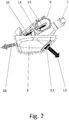
- Fig. 2 a side view of the modular windshield washer
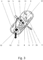
- Fig. 3 a perspective view of the modular windscreen washer
- the Fig. 4 a perspective view of the modular windscreen washer in a sectional view
- the Fig. 5 a block diagram of the windscreen washer system with related functional elements.
- the Fig. 1 shows a motor vehicle with the hood open 1 and open engine compartment.
- modules of a windshield washer are arranged 2 , which are usually in pairs be installed and are intended to control a spray jet 26 on a windshield.
- Fig. 2 . 3 Like the attached Fig. 2 . 3 .
- the module of the windscreen washer 2 consists of a holder of the modular windscreen washer 3 , a nozzle housing 4 with adjustable inclination, from a mop water inlet 5 with connected supply hose, which is performed together with the conductors in the vehicle harness, from a windshield washer 6 , the Outlet is aligned through an opening 7 in the holder of the modular windscreen washer system 3 with the hood closed 1 on the windshield, further comprising a watertight input connector 8 with electrical contacts with which the module of the windshield washer 2 via a guided in the vehicle harness connecting conductor 18 to a central control unit 17 of the Vehicle is connected, and from an adjusting screw 9 , with the inclination of the nozzle housing 4 is set.
- the module of the windshield washing system 2 further comprises an electric heating element 10 , which provides the electrical heating of the windshield washer nozzle 6 and is advantageously also used in the lighting function.
- the lighting element 12 in the holder of the modular windscreen washer system 3 is located on a separate support 11, the lighting element 12 as a source of white light 13 , which is directed with the bonnet open from the holder of the modular windshield washer system 3 in the engine compartment.
- the electric heating element 10 is arranged on the carrier 14 , on which further an electronic element 15 is arranged.
- the carrier 14 is encapsulated in the nozzle housing 4 .
- the electronic element 15 and the heating element 10 are electrically connected, on the one hand within the nozzle housing 4 with fixed connections both with each other, as well as electrical contacts of the input connector 8 , on the other hand to the outside by a flexible conductor 16 with the lighting element 12 , the at one separate carrier 11 in the holder of the modular Windscreen washer 3 is arranged.
- the flexible conductor 16 allows mutual movement of the nozzle housing 4 relative to the holder of the modular windshield washer system 3 when adjusting the inclination of the windshield washer nozzle 6 with the adjusting screw .
- 9 To the central control unit 17 are on the one hand actuators 20 of the vehicle and various other sensors, such as Wischiganstandsparler 21 , outdoor temperature sensor 22 , outdoor light sensor 23 , hood button 24 , etc. connected.
- the advantage of the present solution is that for the realization and control of both functionalities only an already existing control output and a connecting conductor 18 from the central control unit 17, which is already supplied to the input plug 8 , and further the existing second conductor, namely ground potential conductor 27 , via the body connected to the negative terminal of the car battery 19 , can suffice. On the vehicle, no additional conductors, fasteners, flow sleeves, switching contacts, etc. must be added.
- both the functionality of the heating the washer nozzle are configured 6 (for example, depending on the inclusion of an ignition, an engine running, the state of a car battery 19, the outside temperature, the vehicle speed, the washer fluid tank stand 25), as well as the functionality of the engine room lighting.
- the lighting can be configured, for example, depending on the state of a bonnet button 24 , an outside light sensor 23 , the setting of a light switch and other vehicle conditions.
- the central control unit 17 worried about a common connecting conductor 18 on the one hand, the power supply (for heating the windshield washer 6 and for the operation of the lighting element 12 in the engine compartment), on the other hand, the control pulses with which the central control unit 17 of the module windshield washer 2 with heating and lighting function Operating mode determines, ie activation, deactivation of heating and lighting. These control pulses are evaluated by the electronic element 15 , which actively distributes the energy between heating and lighting.
- the electrical heating element 10 fulfills its primary function, ie converts the electrical energy into thermal heat VT , with which the windshield washing nozzle 6 is heated against freezing, on the other hand, it is secondarily advantageously applied in the circuit of the lighting element 12 , where it is to stabilize the operation of the lighting element 12 and used to radiate the associated waste heat of the lighting element ZT2 .
- waste heat ZT1 produced by the active electronic element 15 during operation and the waste heat ZT2 produced by the lighting element 12 , which are otherwise useless would mean heat losses are used here advantageous for heating the wiper water at the inlet 5 , in the windshield washer nozzle 6 and in the opening 7 in the nozzle housing 4 .
- both the electric heating element 10 can continue to operate in emergency mode.
- the electric heating element 10 can continue to operate in emergency mode, in case of failure of the electric heating element 10 , both the heating, and the lighting is disabled.
- the mentioned fault conditions are detected and detected by the central control unit 18 and can be reported to the driver and the service in vehicle diagnosis.
Landscapes
- Engineering & Computer Science (AREA)
- Mechanical Engineering (AREA)
- Water Supply & Treatment (AREA)
- Body Structure For Vehicles (AREA)
Abstract
Vorrichtung zur Beleuchtung eines Fahrzeugmotorraumes, bestehend aus einem an der Innenseite einer Motorhaube (1) angeordneten und einer Frontscheibe anliegenden Modul einer Frontscheibenwaschanlage (2), das eine Scheibenwaschdüse (6), ein elektrisches Heizelement (10) und elektronisches Element (15) umfasst, die über einen Verbindungsstromleiter (18) an ein Zentralsteuergerät (17) des Fahrzeuges angeschlossen sind, wo in dem Modul der Frontscheibenwaschanlage (2) ein Beleuchtungselement (12) angeordnet ist, das über ein elektronisches Element (15) und wenigstens einen Verbindungsleiter (18) an das Zentralsteuergerät (17) des Fahrzeuges und über einen Massepotentialleiter (27) an die Fahrzeugkarosserie angeschlossen ist.Device for illuminating a vehicle engine compartment, comprising a module of a windshield washer system (2) arranged on the inside of a hood (1) and adjacent to a front screen, comprising a windshield washer nozzle (6), an electrical heating element (10) and electronic element (15), which are connected via a connecting conductor (18) to a central control unit (17) of the vehicle, where in the module of the windscreen washer (2) an illumination element (12) is arranged, which via an electronic element (15) and at least one connecting conductor (18) to the central control unit (17) of the vehicle and via a ground potential conductor (27) is connected to the vehicle body.
Description
Die Erfindung betrifft eine Vorrichtung zur Beleuchtung eines Fahrzeugmotorraumes, die an der Innenseite einer Motorhaube angeordnet ist.The invention relates to a device for illuminating a vehicle engine compartment, which is arranged on the inside of a hood.
Derzeit gehört zur Standardausstattung der Kraftfahrzeuge die Beleuchtung des Innenraumes sowie des Kofferraumes, als Komfortausstattung wird die Beleuchtung des Fußbereiches und Türeinstiegsbereiches (Schweller) und dekorative Innenbeleuchtung angeboten, z.B. der Schalttafel, welche eine Orientierung unter verschlechterten Lichtbedingungen ermöglichen und zur Unterstreichung des Nachtdesigns des Fahrzeuges beitragen. Kommt jedoch eine Situation vor, dass im Motorraum irgendwelche Tätigkeiten durchgeführt werden sollen, gerät man in eine konträre Lage, da die meisten Kraftfahrzeuge derzeit mit keinen Einrichtungen zur Motorraumbeleuchtung ausgestattet sind. Die Abwesenheit der Motorraumbeleuchtung bedeutet unter verschlechterten Lichtbedingungen, eventuell in Dunkelheit, eine deutliche Einschränkung oder sogar Verhinderung der Durchführung von üblichen betriebsbedingten Arbeiten, wie z.B. das Nachfüllen des Wischwasserbehälters, den Austausch von fehlerhaften Lampen, die Kontrolle des Öl- oder Kühlflüssigkeitsstandes, der Elektrosicherungen und die Hilfe beim Starten mit Startkabeln. Gewisse Lösung dieser Aufgabe stellt die Nutzung von separaten, ab Werk verbauten oder nachgerüsteten elektrischen Leuchteinheiten dar. Aus der Patentschrift
Die Aufgabe wird durch eine Vorrichtung zur Beleuchtung eines Fahrzeugmotorraumes gelöst, die aus einem an der Innenseite einer Motorhaube angeordneten und einer Frontscheibe anliegenden Modul der Frontscheibenwaschanlage besteht, das ein Düsengehäuse mit Waschwasseranschluss und Scheibenwaschdüse umfasst, wo in dem Düsengehäuse ein elektrisches Heizelement der Düse sowie ein elektronisches Element angeordnet sind, die über einen Stromleiter an das Zentralsteuergerät des Fahrzeuges angeschlossen sind. Die Darstellung der Erfindung liegt darin, dass im Modul der Frontscheibenwaschanlage ein Beleuchtungselement angeordnet ist.The object is achieved by a device for illuminating a vehicle engine compartment, which consists of a arranged on the inside of a hood and a windscreen module of the windscreen washer system comprising a nozzle housing with wash water connection and windscreen washer, where in the nozzle housing an electric heating element of the nozzle and a electronic element are arranged, which are connected via a conductor to the central control unit of the vehicle. The illustration of the invention lies in the fact that a lighting element is arranged in the module of the windscreen washer system.
Die Darstellung liegt ebenfalls darin, dass das Beleuchtungselement über ein elektronisches Element und Stromleiter an ein Zentralsteuergerät des Fahrzeuges angeschlossen ist, womit eine intelligente Steuerung sowohl der Beheizung, wie auch der Beleuchtung ermöglicht wird.The illustration also lies in the fact that the lighting element is connected via an electronic element and conductor to a central control unit of the vehicle, whereby an intelligent control of both the heating, as well as the lighting is made possible.
Als Beleuchtungselement wird vorteilhaft eine LED-Lichtquelle verwendet.As the lighting element, an LED light source is advantageously used.
Um die Leuchtfunktion zu stabilisieren, weist das Beleuchtungselement auch ein elektrisches Heizelement und elektronisches Element auf.In order to stabilize the lighting function, the lighting element also has an electric heating element and electronic element.
Ferner liegt dieser Lösung zugrunde, dass die im elektronischen Element sowie im Beleuchtungselement natürlich entstandene Abwärme zur Beheizung der Scheibenwaschdüse beiträgt.Furthermore, this solution is based on the fact that the naturally occurring in the electronic element and the lighting element waste heat contributes to the heating of the windshield washer nozzle.
Der Vorteil dieser konstruktiven Anordnung liegt darin, dass die Steuerung der Beheizung sowie der Beleuchtung über einen Stromleiter vom Zentralsteuergerät erfolgt, wobei die Lösung keine konstruktive Anpassungen des Fahrzeuges, zusätzliche Leiter oder andere Befestigungsmittel erfordert.The advantage of this constructive arrangement is that the control of the heating and lighting via a conductor made by the central control unit, the solution requires no structural adjustments of the vehicle, additional ladder or other fasteners.
Die Erfindung wird anhand der Ausführungsbeispiele gemäß den beigefügten Zeichnungen näher erläutert, in denen zeigen die
Die
Intelligente Steuerung des Moduls der Frontscheibenwaschanlage 2 besorgt das Zentralsteuergerät 17 des Fahrzeuges in Zusammenarbeit mit dem elektronischen Element 15. In diesem Steuergerät ist mittels einer Programmausstattung (SW) und individuellen Einstellungen, die bei der Fahrzeugfertigung in seinen Speicher eingespielt werden (entsprechend der angebotenen Spezifikation des Herstellers und gemäß der Kundennachfrage), das gewünschte Verhalten sowohl der Heizfunktion, wie auch der Funktion der Beleuchtung des Motorraumes eingestellt.Intelligent control of the module of the
Der Vorteil der vorliegenden Lösung liegt darin, dass zur Realisierung und Steuerung beider Funktionalitäten nur ein bereits vorhandener Steuerausgang sowie ein Verbindungsleiter 18 vom Zentralsteuergerät 17, der bereits zum Eingangsstecker 8 zugeführt ist, und weiter der vorhandene zweite Leiter, und zwar Massepotentialleiter 27, der über die Karosserie zum Minuspol der Autobatterie 19 angeschlossen ist, ausreichen können. Am Fahrzeug müssen keine weitere Stromleiter, Befestigungen, Durchlaufhülsen, Schaltkontakte usw. ergänzt werden.The advantage of the present solution is that for the realization and control of both functionalities only an already existing control output and a connecting
Entsprechend der Anzahl und den Typen der elektronischen Geber, welche an die Eingänge des Zentralsteuergerätes angeschlossen und im jeweiligen Fahrzeug vorhanden sind, kann sowohl die Funktionalität der Beheizung der Scheibenwaschdüse 6 (z.B. in Abhängigkeit von der Einschaltung einer Zündung, einem Motorlauf, dem Zustand einer Autobatterie 19, der Außentemperatur, der Fahrzeuggeschwindigkeit, des Wischwasserbehälterstandes 25), als auch die Funktionalität der Motorraumbeleuchtung konfiguriert werden. Die Beleuchtung kann z.B. in Abhängigkeit vom Zustand eines Motorhaubentasters 24, eines Außenlichtfühlers 23, der Einstellung eines Lichtschalters und weiterer Fahrzeugzustände konfiguriert werden.Depending on the number and types of electronic encoder, which are connected to the inputs of the central control unit and present in each vehicle, both the functionality of the heating the washer nozzle are configured 6 (for example, depending on the inclusion of an ignition, an engine running, the state of a
Das Zentralsteuergerät 17 besorgt über einen gemeinsamen Verbindungsleiter 18 einerseits die Stromeinspeisung (für die Beheizung der Scheibenwaschdüse 6 und für den Betrieb des Beleuchtungselementes 12 im Motorraum), anderseits die Steuerungsimpulse, mit denen das Zentralsteuergerät 17 des Moduls der Frontscheibenwaschanlage 2 mit Heiz- und Beleuchtungsfunktion den Betriebsmodus bestimmt, d.h. Aktivierung, Deaktivierung der Beheizung sowie Beleuchtung. Diese Steuerungsimpulse werden vom elektronischen Element 15 ausgewertet, welches die Energie zwischen Beheizung und Beleuchtung aktiv verteilt.The
Das elektrische Heizelement 10 erfüllt einerseits seine primäre Funktion, d.h. wandelt die elektrische Energie in Heizwärme VT um, mit der die Scheibenwaschdüse 6 gegen Einfrieren beheizt wird, anderseits wird es sekundär vorteilhaft im Stromkreis des Beleuchtungselementes 12 angewendet, wo es zur Stabilisierung des Betriebes des Beleuchtungselementes 12 und zum Abstrahlen der damit verbundener Abwärme des Beleuchtungselementes ZT2 genutzt.The
Die Abwärme ZT1, die bei dem Betrieb vom aktiven elektronischen Element 15 produziert wird, sowie die Abwärme ZT2, die vom Beleuchtungselement 12 produziert wird, welche anderswo unnützliche Wärmeverluste bedeuten würden, werden hier vorteilhaft zur Beheizung des Wischwassers am Einlass 5, in der Scheibenwaschdüse 6 sowie in der Öffnung 7 im Düsengehäuse 4 genutzt.The waste heat ZT1 produced by the active
Bei einer Störung des elektronischen Elementes 15 können sowohl das elektrische Heizelement 10, als auch das Beleuchtungselement 12 weiterhin im Notmodus funktionieren. Bei einer Störung des Beleuchtungselementes 12 kann das elektrische Heizelement 10 weiterhin im Notmodus funktionieren, bei einer Störung des elektrischen Heizelementes 10 ist sowohl die Beheizung, als auch die Beleuchtung außer Funktion gesetzt.
Die genannten Störzustände werden von dem Zentralsteuergerät 18 erkannt und erfasst und können dem Fahrer sowie dem Service bei Fahrzeugdiagnose gemeldet werden.In a fault of the
The mentioned fault conditions are detected and detected by the
- 1.1.
- MotorhaubeEngine Hood
- 2.Second
- Modul der FrontscheibenwaschanlageModule of the windscreen washer system
- 3.Third
- Halter der modularen FrontscheibenwaschanlageHolder of the modular windscreen washer system
- 4.4th
- Düsengehäusenozzle housing
- 5.5th
- WischwasseranschlussWiping water connection
- 6.6th
- Scheibenwaschdüsewindshield washer
- 7.7th
- Öffnungopening
- 8.8th.
- Eingangssteckerinput connector
- 9.9th
- Einstellschraubeadjustment
- 10.10th
- elektrisches Heizelementelectric heating element
- 11.11th
- separater Trägerseparate carrier
- 12.12th
- Beleuchtungselementlighting element
- 13.13th
- weißes LichtWhite light
- 14.14th
- Trägercarrier
- 15.15th
- elektronisches Elementelectronic element
- 16.16th
- flexibler Stromleiterflexible conductor
- 17.17th
- ZentralsteuergerätCentral control unit
- 18.18th
- Verbindungsleiterconnecting conductors
- 19.19th
- Autobatteriecar battery
- 20.20th
- Betätigungselemente des FahrzeugesActuators of the vehicle
- 21.21st
- WischwasserstandsfühlerWasher fluid level sensor
- 22.22nd
- AußentemperaturfühlerOutdoor temperature sensor
- 23.23rd
- AußenlichtfühlerExternal light sensor
- 24.24th
- Motorhaubentasterbonnet switch
- 25.25th
- WischwasserbehälterWindscreen washer fluid tank
- 26.26th
- WischwasserstrahlWiping water jet
- 27.27th
- MassepotentialleiterGround potential conductor
-
ZT 1
ZT 1 - Abwärme des elektronischen ElementesWaste heat of the electronic element
-
ZT 2
ZT 2 - Abwärmewaste heat
- VTVT
- Heizwärmeheating
Claims (5)
Applications Claiming Priority (1)
| Application Number | Priority Date | Filing Date | Title |
|---|---|---|---|
| CZ2015-727A CZ2015727A3 (en) | 2015-10-13 | 2015-10-13 | A device for illuminating a vehicle's engine compartment |
Publications (2)
| Publication Number | Publication Date |
|---|---|
| EP3159227A1 true EP3159227A1 (en) | 2017-04-26 |
| EP3159227B1 EP3159227B1 (en) | 2018-09-05 |
Family
ID=57956059
Family Applications (1)
| Application Number | Title | Priority Date | Filing Date |
|---|---|---|---|
| EP16466012.8A Active EP3159227B1 (en) | 2015-10-13 | 2016-10-12 | Device for illuminating a vehicle motor room |
Country Status (2)
| Country | Link |
|---|---|
| EP (1) | EP3159227B1 (en) |
| CZ (1) | CZ2015727A3 (en) |
Cited By (1)
| Publication number | Priority date | Publication date | Assignee | Title |
|---|---|---|---|---|
| US11639155B2 (en) | 2019-08-27 | 2023-05-02 | Ford Global Technologies, Llc | Windshield washer fluid bottle heater |
Citations (3)
| Publication number | Priority date | Publication date | Assignee | Title |
|---|---|---|---|---|
| DE19501210A1 (en) * | 1995-01-17 | 1996-07-18 | Teves Gmbh Alfred | Module for a motor vehicle |
| DE10031445A1 (en) * | 2000-06-28 | 2002-01-10 | Mannesmann Vdo Ag | Device for heating components has heating element with Ohmic resistance and positive temperature coefficient element with resistance increasing exponentially above certain temperature |
| DE102008061475A1 (en) * | 2008-12-10 | 2010-06-24 | Audi Ag | Motor vehicle, has error memory parallely connected to heating resistor and/or resistor formed based on temperature dependency such that current flow through nozzle is measurable by current sensor of controller at specific temperatures |
-
2015
- 2015-10-13 CZ CZ2015-727A patent/CZ2015727A3/en unknown
-
2016
- 2016-10-12 EP EP16466012.8A patent/EP3159227B1/en active Active
Patent Citations (3)
| Publication number | Priority date | Publication date | Assignee | Title |
|---|---|---|---|---|
| DE19501210A1 (en) * | 1995-01-17 | 1996-07-18 | Teves Gmbh Alfred | Module for a motor vehicle |
| DE10031445A1 (en) * | 2000-06-28 | 2002-01-10 | Mannesmann Vdo Ag | Device for heating components has heating element with Ohmic resistance and positive temperature coefficient element with resistance increasing exponentially above certain temperature |
| DE102008061475A1 (en) * | 2008-12-10 | 2010-06-24 | Audi Ag | Motor vehicle, has error memory parallely connected to heating resistor and/or resistor formed based on temperature dependency such that current flow through nozzle is measurable by current sensor of controller at specific temperatures |
Cited By (1)
| Publication number | Priority date | Publication date | Assignee | Title |
|---|---|---|---|---|
| US11639155B2 (en) | 2019-08-27 | 2023-05-02 | Ford Global Technologies, Llc | Windshield washer fluid bottle heater |
Also Published As
| Publication number | Publication date |
|---|---|
| EP3159227B1 (en) | 2018-09-05 |
| CZ2015727A3 (en) | 2017-04-26 |
Similar Documents
| Publication | Publication Date | Title |
|---|---|---|
| EP3139711B1 (en) | Electronics device and rear view device | |
| DE19511755C1 (en) | Multiplex control of components or subsystems in motor vehicles | |
| DE102006055411B4 (en) | Ventilation, air conditioning or / and heating system with improved ventilation unit | |
| DE102015214781A1 (en) | Adjusting device with a power-operated adjustable flap | |
| DE102011009318A1 (en) | Safety belt for motor vehicles, has safety belt with hose section that extends in longitudinal direction in which electrical or electronic unit of seat belt is inserted | |
| EP2048748A2 (en) | Device for connection to a connection plug of a motor vehicle | |
| DE4221972C2 (en) | Circuit arrangement for a windshield wiper and washer system in motor vehicles | |
| DE3922230A1 (en) | Electrical circuit for motor vehicle windscreen wiper and washer - is simplified by provision of cable for encoded commands from multiple switch to common control unit | |
| EP3159227B1 (en) | Device for illuminating a vehicle motor room | |
| WO2015086098A1 (en) | Method and device for checking a functionality of a lighting device of a motor vehicle exterior lighting unit | |
| EP2870875B1 (en) | Valve assembly for syringe devices for agricultural technology and field sprayer | |
| EP3420163B1 (en) | Motor vehicle locking mechanism | |
| DE19644292C2 (en) | Electronics unit for vehicles | |
| DE19738609A1 (en) | Car mirror, especially outside mirror | |
| DE102017220805A1 (en) | Vehicle device and method for operating a vehicle device | |
| DE102017212610A1 (en) | Housing for receiving and disguising electrical or electronic components of a motor vehicle, motor vehicle with such a housing and method for producing such a housing | |
| DE102006058587A1 (en) | Electrical connection box | |
| DE10141263B4 (en) | Modular vehicle | |
| DE3935889A1 (en) | Remote radio controlled vehicle heating system - uses radio receiver integrated with appts. to be controlled to form unit mountable in bonnet | |
| DE102016100389B4 (en) | electric drive system | |
| DE10214609B4 (en) | Steering wheel for a vehicle | |
| DE4206335A1 (en) | Flashing indicator switch unit for motor vehicles and trailers - is installed in readily accessible position for finger-pressure operation establishing electrical contacts for direction and alarm lamps | |
| DE102019101559A1 (en) | Lighting unit, illuminable component and method for its production | |
| EP3600929A1 (en) | Electric heating appliance | |
| DE102013022459B4 (en) | sprayer |
Legal Events
| Date | Code | Title | Description |
|---|---|---|---|
| PUAI | Public reference made under article 153(3) epc to a published international application that has entered the european phase |
Free format text: ORIGINAL CODE: 0009012 |
|
| AK | Designated contracting states |
Kind code of ref document: A1 Designated state(s): AL AT BE BG CH CY CZ DE DK EE ES FI FR GB GR HR HU IE IS IT LI LT LU LV MC MK MT NL NO PL PT RO RS SE SI SK SM TR |
|
| AX | Request for extension of the european patent |
Extension state: BA ME |
|
| 17P | Request for examination filed |
Effective date: 20171026 |
|
| RBV | Designated contracting states (corrected) |
Designated state(s): AL AT BE BG CH CY CZ DE DK EE ES FI FR GB GR HR HU IE IS IT LI LT LU LV MC MK MT NL NO PL PT RO RS SE SI SK SM TR |
|
| GRAP | Despatch of communication of intention to grant a patent |
Free format text: ORIGINAL CODE: EPIDOSNIGR1 |
|
| INTG | Intention to grant announced |
Effective date: 20180522 |
|
| GRAS | Grant fee paid |
Free format text: ORIGINAL CODE: EPIDOSNIGR3 |
|
| GRAA | (expected) grant |
Free format text: ORIGINAL CODE: 0009210 |
|
| AK | Designated contracting states |
Kind code of ref document: B1 Designated state(s): AL AT BE BG CH CY CZ DE DK EE ES FI FR GB GR HR HU IE IS IT LI LT LU LV MC MK MT NL NO PL PT RO RS SE SI SK SM TR |
|
| REG | Reference to a national code |
Ref country code: GB Ref legal event code: FG4D Free format text: NOT ENGLISH |
|
| REG | Reference to a national code |
Ref country code: CH Ref legal event code: EP |
|
| REG | Reference to a national code |
Ref country code: AT Ref legal event code: REF Ref document number: 1037431 Country of ref document: AT Kind code of ref document: T Effective date: 20180915 |
|
| REG | Reference to a national code |
Ref country code: DE Ref legal event code: R096 Ref document number: 502016001872 Country of ref document: DE |
|
| REG | Reference to a national code |
Ref country code: IE Ref legal event code: FG4D Free format text: LANGUAGE OF EP DOCUMENT: GERMAN |
|
| REG | Reference to a national code |
Ref country code: NL Ref legal event code: MP Effective date: 20180905 |
|
| REG | Reference to a national code |
Ref country code: LT Ref legal event code: MG4D |
|
| REG | Reference to a national code |
Ref country code: SE Ref legal event code: TRGR |
|
| PG25 | Lapsed in a contracting state [announced via postgrant information from national office to epo] |
Ref country code: LT Free format text: LAPSE BECAUSE OF FAILURE TO SUBMIT A TRANSLATION OF THE DESCRIPTION OR TO PAY THE FEE WITHIN THE PRESCRIBED TIME-LIMIT Effective date: 20180905 Ref country code: FI Free format text: LAPSE BECAUSE OF FAILURE TO SUBMIT A TRANSLATION OF THE DESCRIPTION OR TO PAY THE FEE WITHIN THE PRESCRIBED TIME-LIMIT Effective date: 20180905 Ref country code: RS Free format text: LAPSE BECAUSE OF FAILURE TO SUBMIT A TRANSLATION OF THE DESCRIPTION OR TO PAY THE FEE WITHIN THE PRESCRIBED TIME-LIMIT Effective date: 20180905 Ref country code: GR Free format text: LAPSE BECAUSE OF FAILURE TO SUBMIT A TRANSLATION OF THE DESCRIPTION OR TO PAY THE FEE WITHIN THE PRESCRIBED TIME-LIMIT Effective date: 20181206 Ref country code: NO Free format text: LAPSE BECAUSE OF FAILURE TO SUBMIT A TRANSLATION OF THE DESCRIPTION OR TO PAY THE FEE WITHIN THE PRESCRIBED TIME-LIMIT Effective date: 20181205 Ref country code: BG Free format text: LAPSE BECAUSE OF FAILURE TO SUBMIT A TRANSLATION OF THE DESCRIPTION OR TO PAY THE FEE WITHIN THE PRESCRIBED TIME-LIMIT Effective date: 20181205 |
|
| PGFP | Annual fee paid to national office [announced via postgrant information from national office to epo] |
Ref country code: CZ Payment date: 20181211 Year of fee payment: 3 |
|
| PG25 | Lapsed in a contracting state [announced via postgrant information from national office to epo] |
Ref country code: HR Free format text: LAPSE BECAUSE OF FAILURE TO SUBMIT A TRANSLATION OF THE DESCRIPTION OR TO PAY THE FEE WITHIN THE PRESCRIBED TIME-LIMIT Effective date: 20180905 Ref country code: AL Free format text: LAPSE BECAUSE OF FAILURE TO SUBMIT A TRANSLATION OF THE DESCRIPTION OR TO PAY THE FEE WITHIN THE PRESCRIBED TIME-LIMIT Effective date: 20180905 Ref country code: LV Free format text: LAPSE BECAUSE OF FAILURE TO SUBMIT A TRANSLATION OF THE DESCRIPTION OR TO PAY THE FEE WITHIN THE PRESCRIBED TIME-LIMIT Effective date: 20180905 |
|
| PG25 | Lapsed in a contracting state [announced via postgrant information from national office to epo] |
Ref country code: IT Free format text: LAPSE BECAUSE OF FAILURE TO SUBMIT A TRANSLATION OF THE DESCRIPTION OR TO PAY THE FEE WITHIN THE PRESCRIBED TIME-LIMIT Effective date: 20180905 Ref country code: ES Free format text: LAPSE BECAUSE OF FAILURE TO SUBMIT A TRANSLATION OF THE DESCRIPTION OR TO PAY THE FEE WITHIN THE PRESCRIBED TIME-LIMIT Effective date: 20180905 Ref country code: NL Free format text: LAPSE BECAUSE OF FAILURE TO SUBMIT A TRANSLATION OF THE DESCRIPTION OR TO PAY THE FEE WITHIN THE PRESCRIBED TIME-LIMIT Effective date: 20180905 Ref country code: RO Free format text: LAPSE BECAUSE OF FAILURE TO SUBMIT A TRANSLATION OF THE DESCRIPTION OR TO PAY THE FEE WITHIN THE PRESCRIBED TIME-LIMIT Effective date: 20180905 Ref country code: EE Free format text: LAPSE BECAUSE OF FAILURE TO SUBMIT A TRANSLATION OF THE DESCRIPTION OR TO PAY THE FEE WITHIN THE PRESCRIBED TIME-LIMIT Effective date: 20180905 Ref country code: PL Free format text: LAPSE BECAUSE OF FAILURE TO SUBMIT A TRANSLATION OF THE DESCRIPTION OR TO PAY THE FEE WITHIN THE PRESCRIBED TIME-LIMIT Effective date: 20180905 Ref country code: IS Free format text: LAPSE BECAUSE OF FAILURE TO SUBMIT A TRANSLATION OF THE DESCRIPTION OR TO PAY THE FEE WITHIN THE PRESCRIBED TIME-LIMIT Effective date: 20190105 |
|
| PG25 | Lapsed in a contracting state [announced via postgrant information from national office to epo] |
Ref country code: SK Free format text: LAPSE BECAUSE OF FAILURE TO SUBMIT A TRANSLATION OF THE DESCRIPTION OR TO PAY THE FEE WITHIN THE PRESCRIBED TIME-LIMIT Effective date: 20180905 Ref country code: PT Free format text: LAPSE BECAUSE OF FAILURE TO SUBMIT A TRANSLATION OF THE DESCRIPTION OR TO PAY THE FEE WITHIN THE PRESCRIBED TIME-LIMIT Effective date: 20190105 Ref country code: SM Free format text: LAPSE BECAUSE OF FAILURE TO SUBMIT A TRANSLATION OF THE DESCRIPTION OR TO PAY THE FEE WITHIN THE PRESCRIBED TIME-LIMIT Effective date: 20180905 |
|
| REG | Reference to a national code |
Ref country code: DE Ref legal event code: R097 Ref document number: 502016001872 Country of ref document: DE |
|
| REG | Reference to a national code |
Ref country code: BE Ref legal event code: MM Effective date: 20181031 |
|
| PG25 | Lapsed in a contracting state [announced via postgrant information from national office to epo] |
Ref country code: LU Free format text: LAPSE BECAUSE OF NON-PAYMENT OF DUE FEES Effective date: 20181012 |
|
| PLBE | No opposition filed within time limit |
Free format text: ORIGINAL CODE: 0009261 |
|
| STAA | Information on the status of an ep patent application or granted ep patent |
Free format text: STATUS: NO OPPOSITION FILED WITHIN TIME LIMIT |
|
| REG | Reference to a national code |
Ref country code: IE Ref legal event code: MM4A |
|
| PG25 | Lapsed in a contracting state [announced via postgrant information from national office to epo] |
Ref country code: MC Free format text: LAPSE BECAUSE OF FAILURE TO SUBMIT A TRANSLATION OF THE DESCRIPTION OR TO PAY THE FEE WITHIN THE PRESCRIBED TIME-LIMIT Effective date: 20180905 Ref country code: DK Free format text: LAPSE BECAUSE OF FAILURE TO SUBMIT A TRANSLATION OF THE DESCRIPTION OR TO PAY THE FEE WITHIN THE PRESCRIBED TIME-LIMIT Effective date: 20180905 |
|
| 26N | No opposition filed |
Effective date: 20190606 |
|
| PG25 | Lapsed in a contracting state [announced via postgrant information from national office to epo] |
Ref country code: SI Free format text: LAPSE BECAUSE OF FAILURE TO SUBMIT A TRANSLATION OF THE DESCRIPTION OR TO PAY THE FEE WITHIN THE PRESCRIBED TIME-LIMIT Effective date: 20180905 Ref country code: BE Free format text: LAPSE BECAUSE OF NON-PAYMENT OF DUE FEES Effective date: 20181031 |
|
| PG25 | Lapsed in a contracting state [announced via postgrant information from national office to epo] |
Ref country code: FR Free format text: LAPSE BECAUSE OF NON-PAYMENT OF DUE FEES Effective date: 20181105 Ref country code: IE Free format text: LAPSE BECAUSE OF NON-PAYMENT OF DUE FEES Effective date: 20181012 |
|
| PG25 | Lapsed in a contracting state [announced via postgrant information from national office to epo] |
Ref country code: MT Free format text: LAPSE BECAUSE OF FAILURE TO SUBMIT A TRANSLATION OF THE DESCRIPTION OR TO PAY THE FEE WITHIN THE PRESCRIBED TIME-LIMIT Effective date: 20180905 |
|
| PG25 | Lapsed in a contracting state [announced via postgrant information from national office to epo] |
Ref country code: TR Free format text: LAPSE BECAUSE OF FAILURE TO SUBMIT A TRANSLATION OF THE DESCRIPTION OR TO PAY THE FEE WITHIN THE PRESCRIBED TIME-LIMIT Effective date: 20180905 |
|
| REG | Reference to a national code |
Ref country code: CH Ref legal event code: PL |
|
| PG25 | Lapsed in a contracting state [announced via postgrant information from national office to epo] |
Ref country code: MK Free format text: LAPSE BECAUSE OF NON-PAYMENT OF DUE FEES Effective date: 20180905 Ref country code: HU Free format text: LAPSE BECAUSE OF FAILURE TO SUBMIT A TRANSLATION OF THE DESCRIPTION OR TO PAY THE FEE WITHIN THE PRESCRIBED TIME-LIMIT; INVALID AB INITIO Effective date: 20161012 Ref country code: CY Free format text: LAPSE BECAUSE OF FAILURE TO SUBMIT A TRANSLATION OF THE DESCRIPTION OR TO PAY THE FEE WITHIN THE PRESCRIBED TIME-LIMIT Effective date: 20180905 |
|
| PG25 | Lapsed in a contracting state [announced via postgrant information from national office to epo] |
Ref country code: CH Free format text: LAPSE BECAUSE OF NON-PAYMENT OF DUE FEES Effective date: 20191031 Ref country code: LI Free format text: LAPSE BECAUSE OF NON-PAYMENT OF DUE FEES Effective date: 20191031 Ref country code: CZ Free format text: LAPSE BECAUSE OF NON-PAYMENT OF DUE FEES Effective date: 20191012 |
|
| GBPC | Gb: european patent ceased through non-payment of renewal fee |
Effective date: 20201012 |
|
| PG25 | Lapsed in a contracting state [announced via postgrant information from national office to epo] |
Ref country code: GB Free format text: LAPSE BECAUSE OF NON-PAYMENT OF DUE FEES Effective date: 20201012 |
|
| REG | Reference to a national code |
Ref country code: AT Ref legal event code: MM01 Ref document number: 1037431 Country of ref document: AT Kind code of ref document: T Effective date: 20211012 |
|
| PG25 | Lapsed in a contracting state [announced via postgrant information from national office to epo] |
Ref country code: AT Free format text: LAPSE BECAUSE OF NON-PAYMENT OF DUE FEES Effective date: 20211012 |
|
| P01 | Opt-out of the competence of the unified patent court (upc) registered |
Effective date: 20230608 |
|
| PGFP | Annual fee paid to national office [announced via postgrant information from national office to epo] |
Ref country code: SE Payment date: 20230628 Year of fee payment: 8 |
|
| PGFP | Annual fee paid to national office [announced via postgrant information from national office to epo] |
Ref country code: DE Payment date: 20230630 Year of fee payment: 8 |