EP3159207A1 - Restraining device for child safety seat - Google Patents
Restraining device for child safety seat Download PDFInfo
- Publication number
- EP3159207A1 EP3159207A1 EP16175567.3A EP16175567A EP3159207A1 EP 3159207 A1 EP3159207 A1 EP 3159207A1 EP 16175567 A EP16175567 A EP 16175567A EP 3159207 A1 EP3159207 A1 EP 3159207A1
- Authority
- EP
- European Patent Office
- Prior art keywords
- attachment
- cavity
- restraining device
- secured
- locking
- Prior art date
- Legal status (The legal status is an assumption and is not a legal conclusion. Google has not performed a legal analysis and makes no representation as to the accuracy of the status listed.)
- Granted
Links
Images


Classifications
-
- B—PERFORMING OPERATIONS; TRANSPORTING
- B60—VEHICLES IN GENERAL
- B60N—SEATS SPECIALLY ADAPTED FOR VEHICLES; VEHICLE PASSENGER ACCOMMODATION NOT OTHERWISE PROVIDED FOR
- B60N2/00—Seats specially adapted for vehicles; Arrangement or mounting of seats in vehicles
- B60N2/24—Seats specially adapted for vehicles; Arrangement or mounting of seats in vehicles for particular purposes or particular vehicles
- B60N2/26—Seats specially adapted for vehicles; Arrangement or mounting of seats in vehicles for particular purposes or particular vehicles for children
- B60N2/28—Seats readily mountable on, and dismountable from, existing seats or other parts of the vehicle
- B60N2/2887—Fixation to a transversal anchorage bar, e.g. isofix
Definitions
- the invention relates to child safety seats and more particularly to a restraining device for a child safety seat complying with ISOFIX.
- ISOFIX is the international standard for attachment points for child safety seats in passenger cars.
- ISOFIX specifies the anchoring system for child safety seats. It defines standard attachment points to be manufactured into cars, enabling compliant child safety seats to be quickly and safely secured.
- locks of conventional ISOFIX devices have simple construction, inferior mechanism and low safety factor, and are prone to malfunction.
- each attachment assembly comprises an attachment unit secured to the crossbar; an attachment member pivotably fastened in the attachment unit and including first and second cavities; a spring biased first locking member having one end moveably disposed in the first cavity; a second locking member engaged the attachment member; a spring biased moveable member having one end secured to both the first locking member and the second locking member; and a spring biased lock pivotably secured to the moveable member; wherein an attachment point is received in the second cavity in a locked state or clears the second cavity in an unlocked state.
- the first locking member includes a main body, a locking element slidably secured to the main body, and a first elastic member biased between the main body and the locking element.
- the lock includes a lever, a following member, a positioning member extending from the lever through the following member into the moveable member to hold in position, and a second elastic member biased between the following member and the lever.
- the third elastic members are biased between the other end of the moveable member and the following member.
- a restraining device for a child safety seat in accordance with the invention comprises the following components as discussed in detail below.
- the attachment assembly 2 comprises an attachment unit 21 including a first member 211, a second member 212 secured to the first member 211, and a cover 213; an attachment member 22 pivotably fastened between the first and second members 211, 212 and including a first cavity 221 and a second cavity 222; a first locking member 23 including a main body 232, a locking element 231 having the other end slidably fastened in the main body 232, and a torsion spring 233 put on a rod portion of the first locking element 231 and biased between the main body 232 and the locking element 231; a second locking member 24 having one end engaged the attachment member 22; a moveable member 25 having one end secured to both the second locking member 24 and the main body 232, the moveable member 25 including two rods 252, a recess 253 between the rods 252, and two torsion springs 251; and a lock 26 including a lever 265, a following member 261, two rod elements 264
- the torsion spring 251 is put on the rod 252 and the corresponding rod element 264.
- the lever 265 is pivotably fastened between the first and second members 211, 212.
- the cover 213 is put on the second member 212 to cover all above components except the lever 265 and the following member 261.
- the torsion spring 263 is compressed, the torsion springs 251 are compressed, the torsion spring 233 is expanded, one end of the second locking member 24 is engaged the attachment member 22, the locking element 231 has one end engaged the first cavity 221, and an attachment point 3 of an automobile clears the second cavity 222.
- an occupant may press an upper portion of the lever 265 to expand the torsion spring 263, expand the torsion springs 251, move both the moveable member 25 and the second locking member 24 toward the attachment point 3 of a passenger car to cause the attachment member 22 to pass the attachment point 3, clockwise rotate the attachment member 22, and push the locking element 231 toward the main body 232, compress the torsion spring 233, dispose one end of the second locking member 24 in the first cavity 221, cause the locking element 231 to partially clear the first cavity 221, and dispose the attachment point 3 in the second cavity 222, thereby locking the retraining device.
Abstract
Description
- The invention relates to child safety seats and more particularly to a restraining device for a child safety seat complying with ISOFIX.
- As more and more families own cars, car traveling has become the top choice for travel for many families owning a car. For families with children, a car is required to install with child safety seats in order to protect safety of the children seated in the car when traveling by car.
- ISOFIX is the international standard for attachment points for child safety seats in passenger cars. ISOFIX specifies the anchoring system for child safety seats. It defines standard attachment points to be manufactured into cars, enabling compliant child safety seats to be quickly and safely secured. Currently, many patent literatures regarding ISOFIX devices exist. For example, Chinese Utility Model Publication Number
CN203623426U entitled "Improved ISOFIX attachment" is characterized by having less components, a simple construction and high production in order to eliminate drawbacks including an excessive number of components, complex assembly and low production associated with the conventional ISOFIX devices. - In addition, locks of conventional ISOFIX devices have simple construction, inferior mechanism and low safety factor, and are prone to malfunction.
- Thus, the need for improvement still exists.
- It is therefore one object of the invention to provide a restraining device for a child safety seat comprising two attachment assemblies; and a crossbar interconnecting the attachment assemblies; wherein each attachment assembly comprises an attachment unit secured to the crossbar; an attachment member pivotably fastened in the attachment unit and including first and second cavities; a spring biased first locking member having one end moveably disposed in the first cavity; a second locking member engaged the attachment member; a spring biased moveable member having one end secured to both the first locking member and the second locking member; and a spring biased lock pivotably secured to the moveable member; wherein an attachment point is received in the second cavity in a locked state or clears the second cavity in an unlocked state.
- Preferably, the first locking member includes a main body, a locking element slidably secured to the main body, and a first elastic member biased between the main body and the locking element.
- Preferably, the lock includes a lever, a following member, a positioning member extending from the lever through the following member into the moveable member to hold in position, and a second elastic member biased between the following member and the lever.
- Preferably, the third elastic members are biased between the other end of the moveable member and the following member.
- The above and other objects, features and advantages of the invention will become apparent from the following detailed description taken with the accompanying drawings.
-
-
FIG. 1 is an exploded view of a restraining device for a child safety seat according to the invention; -
FIG. 2 is a longitudinal sectional view of the assembled restraining device showing its unlocked state; and -
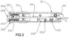
FIG. 3 is a view similar toFIG. 2 showing a locked state of the restraining device. - Referring to
FIGS. 1 to 3 , a restraining device for a child safety seat in accordance with the invention comprises the following components as discussed in detail below. - Two
attachment assemblies 2 are interconnected by acrossbar 1. Theattachment assembly 2 comprises anattachment unit 21 including afirst member 211, asecond member 212 secured to thefirst member 211, and acover 213; anattachment member 22 pivotably fastened between the first andsecond members first cavity 221 and asecond cavity 222; afirst locking member 23 including amain body 232, alocking element 231 having the other end slidably fastened in themain body 232, and atorsion spring 233 put on a rod portion of thefirst locking element 231 and biased between themain body 232 and thelocking element 231; asecond locking member 24 having one end engaged theattachment member 22; amoveable member 25 having one end secured to both thesecond locking member 24 and themain body 232, themoveable member 25 including tworods 252, arecess 253 between therods 252, and twotorsion springs 251; and alock 26 including alever 265, a followingmember 261, tworod elements 264 on an inner surface of the followingmember 261 facing therods 252, apositioning member 262 extending from an inner surface of thelever 265 through the followingmember 261 into therecess 253 to be retained, and atorsion spring 263 biased between the followingmember 261 and thelever 265. Thetorsion spring 251 is put on therod 252 and thecorresponding rod element 264. Thelever 265 is pivotably fastened between the first andsecond members cover 213 is put on thesecond member 212 to cover all above components except thelever 265 and the followingmember 261. - As shown in
FIG. 2 , in an unlocked state of the restraining device, thetorsion spring 263 is compressed, thetorsion springs 251 are compressed, thetorsion spring 233 is expanded, one end of thesecond locking member 24 is engaged theattachment member 22, thelocking element 231 has one end engaged thefirst cavity 221, and anattachment point 3 of an automobile clears thesecond cavity 222. - As shown in
FIG. 3 , an occupant may press an upper portion of thelever 265 to expand thetorsion spring 263, expand thetorsion springs 251, move both themoveable member 25 and thesecond locking member 24 toward theattachment point 3 of a passenger car to cause theattachment member 22 to pass theattachment point 3, clockwise rotate theattachment member 22, and push thelocking element 231 toward themain body 232, compress thetorsion spring 233, dispose one end of thesecond locking member 24 in thefirst cavity 221, cause thelocking element 231 to partially clear thefirst cavity 221, and dispose theattachment point 3 in thesecond cavity 222, thereby locking the retraining device. - While the invention has been described in terms of preferred embodiments, those skilled in the art will recognize that the invention can be practiced with modifications and these modifications are contemplated by the invention.
Claims (4)
- A restraining device for a child safety seat comprising:two attachment assemblies (2); anda crossbar (1) interconnecting the attachment assemblies (2);wherein each attachment assembly (2) comprises:an attachment unit (21) secured to the crossbar (1);an attachment member (22) pivotably fastened in the attachment unit (21) and including a first cavity (221) and a second cavity (222);a spring biased first locking member (23) having one end moveably disposed in the first cavity (221);a second locking member (24) engaged the attachment member (22);a spring biased moveable member (25) having one end secured to both the first locking member (23) and the second locking member (24); anda spring biased lock (26) pivotably secured to the moveable member (25).
- The restraining device of claim 1, wherein the first locking member (23) includes a main body (232), a locking element (231) slidably secured to the main body (232), and a first elastic member (233) biased between the main body (232) and the locking element (231).
- The restraining device of claim 2, wherein the lock (26) includes a lever (265), a following member (261), a positioning member (262) extending from the lever (265) through the following member (261) into the moveable member (25) to hold in position, and a second elastic member (263) biased between the following member (261) and the lever (265).
- The restraining device of claim 3, wherein the third elastic members (251) are biased between the other end of the moveable member (25) and the following member (261).
Priority Applications (1)
| Application Number | Priority Date | Filing Date | Title |
|---|---|---|---|
| PL16175567T PL3159207T3 (en) | 2015-10-23 | 2016-06-21 | Restraining device for child safety seat |
Applications Claiming Priority (1)
| Application Number | Priority Date | Filing Date | Title |
|---|---|---|---|
| CN201520821378.8U CN205113070U (en) | 2015-10-23 | 2015-10-23 | Improved generation safety seat ISOFIX device |
Publications (2)
| Publication Number | Publication Date |
|---|---|
| EP3159207A1 true EP3159207A1 (en) | 2017-04-26 |
| EP3159207B1 EP3159207B1 (en) | 2018-08-01 |
Family
ID=55568709
Family Applications (1)
| Application Number | Title | Priority Date | Filing Date |
|---|---|---|---|
| EP16175567.3A Active EP3159207B1 (en) | 2015-10-23 | 2016-06-21 | Restraining device for child safety seat |
Country Status (4)
| Country | Link |
|---|---|
| EP (1) | EP3159207B1 (en) |
| CN (1) | CN205113070U (en) |
| ES (1) | ES2685721T3 (en) |
| PL (1) | PL3159207T3 (en) |
Cited By (1)
| Publication number | Priority date | Publication date | Assignee | Title |
|---|---|---|---|---|
| CN107187349A (en) * | 2017-07-17 | 2017-09-22 | 联扬塑胶(深圳)有限公司 | Child safety seat bindiny mechanism |
Families Citing this family (2)
| Publication number | Priority date | Publication date | Assignee | Title |
|---|---|---|---|---|
| CN109398180B (en) * | 2018-12-18 | 2023-09-29 | 麦克英孚(宁波)婴童用品有限公司 | ISOFIX release locking mechanism and use its children's safety seat |
| CN111959357B (en) * | 2020-08-28 | 2022-05-17 | 宁波宝贝第一母婴用品有限公司 | ISOFIX mechanism and safety seat |
Citations (2)
| Publication number | Priority date | Publication date | Assignee | Title |
|---|---|---|---|---|
| US20100072798A1 (en) * | 2008-09-25 | 2010-03-25 | Skjp Holdings, Llc | Lower anchor coupling |
| US20110233374A1 (en) * | 2010-03-24 | 2011-09-29 | Skjp Holdings, Llc | Coupling device for securing a child car seat to a vehicle |
-
2015
- 2015-10-23 CN CN201520821378.8U patent/CN205113070U/en active Active
-
2016
- 2016-06-21 EP EP16175567.3A patent/EP3159207B1/en active Active
- 2016-06-21 ES ES16175567.3T patent/ES2685721T3/en active Active
- 2016-06-21 PL PL16175567T patent/PL3159207T3/en unknown
Patent Citations (2)
| Publication number | Priority date | Publication date | Assignee | Title |
|---|---|---|---|---|
| US20100072798A1 (en) * | 2008-09-25 | 2010-03-25 | Skjp Holdings, Llc | Lower anchor coupling |
| US20110233374A1 (en) * | 2010-03-24 | 2011-09-29 | Skjp Holdings, Llc | Coupling device for securing a child car seat to a vehicle |
Cited By (1)
| Publication number | Priority date | Publication date | Assignee | Title |
|---|---|---|---|---|
| CN107187349A (en) * | 2017-07-17 | 2017-09-22 | 联扬塑胶(深圳)有限公司 | Child safety seat bindiny mechanism |
Also Published As
| Publication number | Publication date |
|---|---|
| ES2685721T3 (en) | 2018-10-10 |
| CN205113070U (en) | 2016-03-30 |
| EP3159207B1 (en) | 2018-08-01 |
| PL3159207T3 (en) | 2018-11-30 |
Similar Documents
| Publication | Publication Date | Title |
|---|---|---|
| CN204845856U (en) | Spring bolt mechanism of car blet | |
| EP3159207A1 (en) | Restraining device for child safety seat | |
| EP3495196B1 (en) | Child car safety seat | |
| EP2913222B1 (en) | Child safety seat | |
| DE102013107533A1 (en) | CHILD SAFETY SEAT | |
| EP2679440A1 (en) | Child safety seat | |
| US9028006B2 (en) | Safety bow assembly and child seat including the same | |
| US9119445B2 (en) | Buckle assemblies with lift latches and associated methods and systems | |
| DE102010023403B4 (en) | Headrest, in particular for a motor vehicle | |
| US20120187742A1 (en) | Seat belt buckle and seat belt system for a vehicle | |
| EP2756985A1 (en) | Height adjustment mechanism for head rest of child safety seat | |
| JP7274861B2 (en) | Child seat for car seat installation | |
| US4423905A (en) | Latch mechanism | |
| EP3702208B1 (en) | Car safety seat | |
| JP4580337B2 (en) | Headrest bush and vehicle seat using the same | |
| WO2015043571A3 (en) | Motor vehicle door lock | |
| US20140339863A1 (en) | Device for selectively controlling and reducing the backward displacement of a vehicle seat in the event of an accident | |
| CN111204263B (en) | Seat back adjustment system | |
| EP2072326A1 (en) | An infant seat for motorcars | |
| CN107495542B (en) | Automobile safety belt buckle assembly with high safety performance | |
| US9352672B2 (en) | Inertial latch system for a vehicle seat | |
| CN114604145A (en) | Headrest height adjusting mechanism and child safety seat | |
| CN210310041U (en) | Child safety seat | |
| CN107472188B (en) | Double-pin type high-safety automobile safety belt assembly | |
| CN206344787U (en) | Automobile safety seat belt arrangement for adjusting height |
Legal Events
| Date | Code | Title | Description |
|---|---|---|---|
| PUAI | Public reference made under article 153(3) epc to a published international application that has entered the european phase |
Free format text: ORIGINAL CODE: 0009012 |
|
| STAA | Information on the status of an ep patent application or granted ep patent |
Free format text: STATUS: REQUEST FOR EXAMINATION WAS MADE |
|
| 17P | Request for examination filed |
Effective date: 20160630 |
|
| AK | Designated contracting states |
Kind code of ref document: A1 Designated state(s): AL AT BE BG CH CY CZ DE DK EE ES FI FR GB GR HR HU IE IS IT LI LT LU LV MC MK MT NL NO PL PT RO RS SE SI SK SM TR |
|
| AX | Request for extension of the european patent |
Extension state: BA ME |
|
| GRAP | Despatch of communication of intention to grant a patent |
Free format text: ORIGINAL CODE: EPIDOSNIGR1 |
|
| STAA | Information on the status of an ep patent application or granted ep patent |
Free format text: STATUS: GRANT OF PATENT IS INTENDED |
|
| RIC1 | Information provided on ipc code assigned before grant |
Ipc: B60N 2/28 20060101AFI20180228BHEP |
|
| INTG | Intention to grant announced |
Effective date: 20180316 |
|
| GRAS | Grant fee paid |
Free format text: ORIGINAL CODE: EPIDOSNIGR3 |
|
| GRAA | (expected) grant |
Free format text: ORIGINAL CODE: 0009210 |
|
| STAA | Information on the status of an ep patent application or granted ep patent |
Free format text: STATUS: THE PATENT HAS BEEN GRANTED |
|
| AK | Designated contracting states |
Kind code of ref document: B1 Designated state(s): AL AT BE BG CH CY CZ DE DK EE ES FI FR GB GR HR HU IE IS IT LI LT LU LV MC MK MT NL NO PL PT RO RS SE SI SK SM TR |
|
| REG | Reference to a national code |
Ref country code: GB Ref legal event code: FG4D |
|
| REG | Reference to a national code |
Ref country code: CH Ref legal event code: EP Ref country code: AT Ref legal event code: REF Ref document number: 1023895 Country of ref document: AT Kind code of ref document: T Effective date: 20180815 |
|
| REG | Reference to a national code |
Ref country code: IE Ref legal event code: FG4D |
|
| REG | Reference to a national code |
Ref country code: DE Ref legal event code: R096 Ref document number: 602016004449 Country of ref document: DE |
|
| REG | Reference to a national code |
Ref country code: NL Ref legal event code: FP |
|
| REG | Reference to a national code |
Ref country code: ES Ref legal event code: FG2A Ref document number: 2685721 Country of ref document: ES Kind code of ref document: T3 Effective date: 20181010 |
|
| REG | Reference to a national code |
Ref country code: LT Ref legal event code: MG4D |
|
| REG | Reference to a national code |
Ref country code: AT Ref legal event code: MK05 Ref document number: 1023895 Country of ref document: AT Kind code of ref document: T Effective date: 20180801 |
|
| PG25 | Lapsed in a contracting state [announced via postgrant information from national office to epo] |
Ref country code: FI Free format text: LAPSE BECAUSE OF FAILURE TO SUBMIT A TRANSLATION OF THE DESCRIPTION OR TO PAY THE FEE WITHIN THE PRESCRIBED TIME-LIMIT Effective date: 20180801 Ref country code: SE Free format text: LAPSE BECAUSE OF FAILURE TO SUBMIT A TRANSLATION OF THE DESCRIPTION OR TO PAY THE FEE WITHIN THE PRESCRIBED TIME-LIMIT Effective date: 20180801 Ref country code: BG Free format text: LAPSE BECAUSE OF FAILURE TO SUBMIT A TRANSLATION OF THE DESCRIPTION OR TO PAY THE FEE WITHIN THE PRESCRIBED TIME-LIMIT Effective date: 20181101 Ref country code: AT Free format text: LAPSE BECAUSE OF FAILURE TO SUBMIT A TRANSLATION OF THE DESCRIPTION OR TO PAY THE FEE WITHIN THE PRESCRIBED TIME-LIMIT Effective date: 20180801 Ref country code: RS Free format text: LAPSE BECAUSE OF FAILURE TO SUBMIT A TRANSLATION OF THE DESCRIPTION OR TO PAY THE FEE WITHIN THE PRESCRIBED TIME-LIMIT Effective date: 20180801 Ref country code: IS Free format text: LAPSE BECAUSE OF FAILURE TO SUBMIT A TRANSLATION OF THE DESCRIPTION OR TO PAY THE FEE WITHIN THE PRESCRIBED TIME-LIMIT Effective date: 20181201 Ref country code: GR Free format text: LAPSE BECAUSE OF FAILURE TO SUBMIT A TRANSLATION OF THE DESCRIPTION OR TO PAY THE FEE WITHIN THE PRESCRIBED TIME-LIMIT Effective date: 20181102 Ref country code: NO Free format text: LAPSE BECAUSE OF FAILURE TO SUBMIT A TRANSLATION OF THE DESCRIPTION OR TO PAY THE FEE WITHIN THE PRESCRIBED TIME-LIMIT Effective date: 20181101 Ref country code: LT Free format text: LAPSE BECAUSE OF FAILURE TO SUBMIT A TRANSLATION OF THE DESCRIPTION OR TO PAY THE FEE WITHIN THE PRESCRIBED TIME-LIMIT Effective date: 20180801 |
|
| PG25 | Lapsed in a contracting state [announced via postgrant information from national office to epo] |
Ref country code: HR Free format text: LAPSE BECAUSE OF FAILURE TO SUBMIT A TRANSLATION OF THE DESCRIPTION OR TO PAY THE FEE WITHIN THE PRESCRIBED TIME-LIMIT Effective date: 20180801 Ref country code: LV Free format text: LAPSE BECAUSE OF FAILURE TO SUBMIT A TRANSLATION OF THE DESCRIPTION OR TO PAY THE FEE WITHIN THE PRESCRIBED TIME-LIMIT Effective date: 20180801 Ref country code: AL Free format text: LAPSE BECAUSE OF FAILURE TO SUBMIT A TRANSLATION OF THE DESCRIPTION OR TO PAY THE FEE WITHIN THE PRESCRIBED TIME-LIMIT Effective date: 20180801 |
|
| PG25 | Lapsed in a contracting state [announced via postgrant information from national office to epo] |
Ref country code: RO Free format text: LAPSE BECAUSE OF FAILURE TO SUBMIT A TRANSLATION OF THE DESCRIPTION OR TO PAY THE FEE WITHIN THE PRESCRIBED TIME-LIMIT Effective date: 20180801 Ref country code: CZ Free format text: LAPSE BECAUSE OF FAILURE TO SUBMIT A TRANSLATION OF THE DESCRIPTION OR TO PAY THE FEE WITHIN THE PRESCRIBED TIME-LIMIT Effective date: 20180801 Ref country code: EE Free format text: LAPSE BECAUSE OF FAILURE TO SUBMIT A TRANSLATION OF THE DESCRIPTION OR TO PAY THE FEE WITHIN THE PRESCRIBED TIME-LIMIT Effective date: 20180801 |
|
| REG | Reference to a national code |
Ref country code: DE Ref legal event code: R097 Ref document number: 602016004449 Country of ref document: DE |
|
| PG25 | Lapsed in a contracting state [announced via postgrant information from national office to epo] |
Ref country code: DK Free format text: LAPSE BECAUSE OF FAILURE TO SUBMIT A TRANSLATION OF THE DESCRIPTION OR TO PAY THE FEE WITHIN THE PRESCRIBED TIME-LIMIT Effective date: 20180801 Ref country code: SM Free format text: LAPSE BECAUSE OF FAILURE TO SUBMIT A TRANSLATION OF THE DESCRIPTION OR TO PAY THE FEE WITHIN THE PRESCRIBED TIME-LIMIT Effective date: 20180801 Ref country code: SK Free format text: LAPSE BECAUSE OF FAILURE TO SUBMIT A TRANSLATION OF THE DESCRIPTION OR TO PAY THE FEE WITHIN THE PRESCRIBED TIME-LIMIT Effective date: 20180801 |
|
| PLBE | No opposition filed within time limit |
Free format text: ORIGINAL CODE: 0009261 |
|
| STAA | Information on the status of an ep patent application or granted ep patent |
Free format text: STATUS: NO OPPOSITION FILED WITHIN TIME LIMIT |
|
| 26N | No opposition filed |
Effective date: 20190503 |
|
| PG25 | Lapsed in a contracting state [announced via postgrant information from national office to epo] |
Ref country code: SI Free format text: LAPSE BECAUSE OF FAILURE TO SUBMIT A TRANSLATION OF THE DESCRIPTION OR TO PAY THE FEE WITHIN THE PRESCRIBED TIME-LIMIT Effective date: 20180801 |
|
| PG25 | Lapsed in a contracting state [announced via postgrant information from national office to epo] |
Ref country code: MC Free format text: LAPSE BECAUSE OF FAILURE TO SUBMIT A TRANSLATION OF THE DESCRIPTION OR TO PAY THE FEE WITHIN THE PRESCRIBED TIME-LIMIT Effective date: 20180801 |
|
| REG | Reference to a national code |
Ref country code: CH Ref legal event code: PL |
|
| REG | Reference to a national code |
Ref country code: BE Ref legal event code: MM Effective date: 20190630 |
|
| PG25 | Lapsed in a contracting state [announced via postgrant information from national office to epo] |
Ref country code: TR Free format text: LAPSE BECAUSE OF FAILURE TO SUBMIT A TRANSLATION OF THE DESCRIPTION OR TO PAY THE FEE WITHIN THE PRESCRIBED TIME-LIMIT Effective date: 20180801 |
|
| PG25 | Lapsed in a contracting state [announced via postgrant information from national office to epo] |
Ref country code: IE Free format text: LAPSE BECAUSE OF NON-PAYMENT OF DUE FEES Effective date: 20190621 |
|
| PG25 | Lapsed in a contracting state [announced via postgrant information from national office to epo] |
Ref country code: BE Free format text: LAPSE BECAUSE OF NON-PAYMENT OF DUE FEES Effective date: 20190630 Ref country code: CH Free format text: LAPSE BECAUSE OF NON-PAYMENT OF DUE FEES Effective date: 20190630 Ref country code: LI Free format text: LAPSE BECAUSE OF NON-PAYMENT OF DUE FEES Effective date: 20190630 Ref country code: LU Free format text: LAPSE BECAUSE OF NON-PAYMENT OF DUE FEES Effective date: 20190621 |
|
| PG25 | Lapsed in a contracting state [announced via postgrant information from national office to epo] |
Ref country code: PT Free format text: LAPSE BECAUSE OF FAILURE TO SUBMIT A TRANSLATION OF THE DESCRIPTION OR TO PAY THE FEE WITHIN THE PRESCRIBED TIME-LIMIT Effective date: 20181201 |
|
| PG25 | Lapsed in a contracting state [announced via postgrant information from national office to epo] |
Ref country code: CY Free format text: LAPSE BECAUSE OF FAILURE TO SUBMIT A TRANSLATION OF THE DESCRIPTION OR TO PAY THE FEE WITHIN THE PRESCRIBED TIME-LIMIT Effective date: 20180801 |
|
| PG25 | Lapsed in a contracting state [announced via postgrant information from national office to epo] |
Ref country code: MT Free format text: LAPSE BECAUSE OF FAILURE TO SUBMIT A TRANSLATION OF THE DESCRIPTION OR TO PAY THE FEE WITHIN THE PRESCRIBED TIME-LIMIT Effective date: 20180801 Ref country code: HU Free format text: LAPSE BECAUSE OF FAILURE TO SUBMIT A TRANSLATION OF THE DESCRIPTION OR TO PAY THE FEE WITHIN THE PRESCRIBED TIME-LIMIT; INVALID AB INITIO Effective date: 20160621 |
|
| PG25 | Lapsed in a contracting state [announced via postgrant information from national office to epo] |
Ref country code: MK Free format text: LAPSE BECAUSE OF FAILURE TO SUBMIT A TRANSLATION OF THE DESCRIPTION OR TO PAY THE FEE WITHIN THE PRESCRIBED TIME-LIMIT Effective date: 20180801 |
|
| PGFP | Annual fee paid to national office [announced via postgrant information from national office to epo] |
Ref country code: NL Payment date: 20230525 Year of fee payment: 8 Ref country code: IT Payment date: 20230608 Year of fee payment: 8 Ref country code: FR Payment date: 20230630 Year of fee payment: 8 Ref country code: DE Payment date: 20230613 Year of fee payment: 8 |
|
| PGFP | Annual fee paid to national office [announced via postgrant information from national office to epo] |
Ref country code: PL Payment date: 20230406 Year of fee payment: 8 |
|
| PGFP | Annual fee paid to national office [announced via postgrant information from national office to epo] |
Ref country code: GB Payment date: 20230406 Year of fee payment: 8 Ref country code: ES Payment date: 20230706 Year of fee payment: 8 |