EP2679440A1 - Child safety seat - Google Patents
Child safety seat Download PDFInfo
- Publication number
- EP2679440A1 EP2679440A1 EP13174083.9A EP13174083A EP2679440A1 EP 2679440 A1 EP2679440 A1 EP 2679440A1 EP 13174083 A EP13174083 A EP 13174083A EP 2679440 A1 EP2679440 A1 EP 2679440A1
- Authority
- EP
- European Patent Office
- Prior art keywords
- tubular segment
- child safety
- safety seat
- fastener
- support leg
- Prior art date
- Legal status (The legal status is an assumption and is not a legal conclusion. Google has not performed a legal analysis and makes no representation as to the accuracy of the status listed.)
- Granted
Links
Images


Classifications
-
- B—PERFORMING OPERATIONS; TRANSPORTING
- B60—VEHICLES IN GENERAL
- B60N—SEATS SPECIALLY ADAPTED FOR VEHICLES; VEHICLE PASSENGER ACCOMMODATION NOT OTHERWISE PROVIDED FOR
- B60N2/00—Seats specially adapted for vehicles; Arrangement or mounting of seats in vehicles
- B60N2/24—Seats specially adapted for vehicles; Arrangement or mounting of seats in vehicles for particular purposes or particular vehicles
- B60N2/26—Seats specially adapted for vehicles; Arrangement or mounting of seats in vehicles for particular purposes or particular vehicles for children
- B60N2/28—Seats readily mountable on, and dismountable from, existing seats or other parts of the vehicle
- B60N2/2884—Seats readily mountable on, and dismountable from, existing seats or other parts of the vehicle with protection systems against abnormal g-forces
-
- B—PERFORMING OPERATIONS; TRANSPORTING
- B60—VEHICLES IN GENERAL
- B60N—SEATS SPECIALLY ADAPTED FOR VEHICLES; VEHICLE PASSENGER ACCOMMODATION NOT OTHERWISE PROVIDED FOR
- B60N2/00—Seats specially adapted for vehicles; Arrangement or mounting of seats in vehicles
- B60N2/24—Seats specially adapted for vehicles; Arrangement or mounting of seats in vehicles for particular purposes or particular vehicles
- B60N2/26—Seats specially adapted for vehicles; Arrangement or mounting of seats in vehicles for particular purposes or particular vehicles for children
- B60N2/28—Seats readily mountable on, and dismountable from, existing seats or other parts of the vehicle
- B60N2/2821—Seats readily mountable on, and dismountable from, existing seats or other parts of the vehicle having a seat and a base part
- B60N2/2824—Seats readily mountable on, and dismountable from, existing seats or other parts of the vehicle having a seat and a base part part of the base being supported by the vehicle frame
-
- B—PERFORMING OPERATIONS; TRANSPORTING
- B60—VEHICLES IN GENERAL
- B60N—SEATS SPECIALLY ADAPTED FOR VEHICLES; VEHICLE PASSENGER ACCOMMODATION NOT OTHERWISE PROVIDED FOR
- B60N2/00—Seats specially adapted for vehicles; Arrangement or mounting of seats in vehicles
- B60N2/24—Seats specially adapted for vehicles; Arrangement or mounting of seats in vehicles for particular purposes or particular vehicles
- B60N2/42—Seats specially adapted for vehicles; Arrangement or mounting of seats in vehicles for particular purposes or particular vehicles the seat constructed to protect the occupant from the effect of abnormal g-forces, e.g. crash or safety seats
- B60N2/427—Seats or parts thereof displaced during a crash
- B60N2/42709—Seats or parts thereof displaced during a crash involving residual deformation or fracture of the structure
Definitions
- the present invention relates to child safety seats.
- an automobile vehicle has seatbelts provided at the front and rear seats.
- the seatbelt generally includes shoulder and lap straps that may be fastened with an anchor point of the vehicle to restrain and protect the occupant in case of collision or sudden stop of the vehicle.
- the use of the vehicle seatbelt is not adapted for a young child who has a smaller body and may not be able to sustain the pressure applied by the seatbelt.
- safety legislations require the use of a child safety seat for seating a young child in a vehicle.
- An anchorage fixture provided in the vehicle can securely fasten with the child safety seat, which is more adapted to provide protection for the young child.
- the present application describes a child safety seat that includes a seat base having a shell body, and a support leg connected with the shell body.
- the support leg includes a tubular segment, a support portion, a fastener connected with the tubular segment and the support portion, and a cushioning structure disposed adjacent to the fastener, wherein the cushioning structure is configured to block displacement of the fastener so that the support portion is locked in position relative to the tubular segment, and to deform or break as a result of a displacement of the fastener into the cushioning structure when a substantial force is applied that forces the tubular segment to move relative to the support portion.
- FIG. 1 is a perspective view illustrating an embodiment of a child safety seat
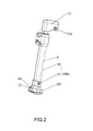
- FIG. 2 is a schematic view illustrating a support leg provided in a seat base of the child safety seat
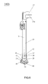
- FIG. 3 is an exploded view of the support leg shown in FIG. 2 ;
- FIG. 4 is a schematic view illustrating the support leg of FIG. 2 in a normal configuration of use
- FIG. 5 is a schematic view illustrating the support leg of FIG. 2 when collision occurs
- FIG. 6 is a schematic view illustrating another embodiment of a support leg suitable for use in a child safety seat
- FIG. 7 is an enlarged view of portion A shown in FIG. 6 ;
- FIG. 8 is a schematic view illustrating the support leg of FIG. 6 when collision occurs
- the tubular segment 10 can extend along a lengthwise axis X of the support leg 100a.
- the tubular segment 10 can have a lower end portion fixedly assembled with the foot portion 20 via a fastener 30.
- the tubular segment 10 can be sleeved and fitted at least partially into the foot portion 20, and the fastener 30 can engage through the tubular segment 10 and the foot portion 20.
- the fastener 30 can be a pin, a rivet, and like elements.
- the foot portion 20 can be thereby affixed with the tubular segment 10, and act as a support portion for the support leg 100a.
Abstract
Description
- This application claims priority of China patent application no.
201210217524.7 filed on June 28, 2012 - 1. Field of the Invention
- The present invention relates to child safety seats.
- 2. Description of the Related Art
- Conventionally, an automobile vehicle has seatbelts provided at the front and rear seats. The seatbelt generally includes shoulder and lap straps that may be fastened with an anchor point of the vehicle to restrain and protect the occupant in case of collision or sudden stop of the vehicle. However, the use of the vehicle seatbelt is not adapted for a young child who has a smaller body and may not be able to sustain the pressure applied by the seatbelt. As a result, safety legislations require the use of a child safety seat for seating a young child in a vehicle. An anchorage fixture provided in the vehicle can securely fasten with the child safety seat, which is more adapted to provide protection for the young child.
- However, when accidental collision occurs, excessive concentration of the collision energy may be transmitted from the restraint harness of the child safety seat to the body of the child. This may cause serious injury to the child.
- Therefore, there is a need for a child safety seat that is safer in use, and can address at least the foregoing issues.
- The present application describes a child safety seat that includes a seat base having a shell body, and a support leg connected with the shell body. The support leg includes a tubular segment, a support portion, a fastener connected with the tubular segment and the support portion, and a cushioning structure disposed adjacent to the fastener, wherein the cushioning structure is configured to block displacement of the fastener so that the support portion is locked in position relative to the tubular segment, and to deform or break as a result of a displacement of the fastener into the cushioning structure when a substantial force is applied that forces the tubular segment to move relative to the support portion.
-
FIG. 1 is a perspective view illustrating an embodiment of a child safety seat; -
FIG. 2 is a schematic view illustrating a support leg provided in a seat base of the child safety seat; -
FIG. 3 is an exploded view of the support leg shown inFIG. 2 ; -
FIG. 4 is a schematic view illustrating the support leg ofFIG. 2 in a normal configuration of use; -
FIG. 5 is a schematic view illustrating the support leg ofFIG. 2 when collision occurs; -
FIG. 6 is a schematic view illustrating another embodiment of a support leg suitable for use in a child safety seat; -
FIG. 7 is an enlarged view of portion A shown inFIG. 6 ; -
FIG. 8 is a schematic view illustrating the support leg ofFIG. 6 when collision occurs; -
FIG. 9 is a schematic view illustrating another variant embodiment of a support leg suitable for use in a child safety seat; -
FIG. 10 is an enlarged view of portion B shown inFIG. 9 ; -
FIG. 11 is a schematic view illustrating the support leg ofFIG. 9 when collision occurs; -
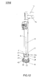
FIG. 12 is a schematic view illustrating another variant embodiment of a support leg suitable for use in a child safety seat; -
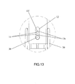
FIG. 13 is an enlarged view of portion C shown inFIG. 12 ; and -
FIG. 14 is a schematic view illustrating the support leg ofFIG. 12 when collision occurs. - The present application describes a
child safety seat 1000 that can include aseat base 200, and a support leg operable to provide support for theseat base 200. Exemplary embodiments of the support leg are described in more details hereafter, including asupport leg 100a as shown inFIG. 2 , asupport leg 100b as shown inFIG. 6 , asupport leg 100c as shown inFIG. 9 , and asupport leg 100d as shown inFIG. 12 . -
FIGS. 1-5 are schematic views illustrating the construction of thesupport leg 100a. Theseat base 200 can have a shell body connected with thesupport leg 100a. Thesupport leg 100a can include atubular segment 10 and afoot portion 20. An upper end portion of thetubular segment 10 can be assembled with a shell body of theseat base 200. For example, the upper end portion of thetubular segment 10 can be pivotally connected with the shell body of theseat base 200 via apivot joint 15. Thetubular segment 10 can be affixed with thepivot joint 15, and thepivot joint 15 can include ahole 15a through which a shaft affixed with theseat base 200 can be assembled. Thesupport leg 100a can be thereby operable to rotate relative to the shell body of theseat base 200 between a deployed position extending downward from the shell body for providing support, and a folded position close to the bottom of the shell body for storage. - The
tubular segment 10 can extend along a lengthwise axis X of thesupport leg 100a. Thetubular segment 10 can have a lower end portion fixedly assembled with thefoot portion 20 via afastener 30. For example, thetubular segment 10 can be sleeved and fitted at least partially into thefoot portion 20, and thefastener 30 can engage through thetubular segment 10 and thefoot portion 20. Thefastener 30 can be a pin, a rivet, and like elements. Thefoot portion 20 can be thereby affixed with thetubular segment 10, and act as a support portion for thesupport leg 100a. - The
support leg 100a can also include a cushioning structure that can block displacement of thefastener 30 so that thefoot portion 20 is locked in position relative to thetubular segment 10, and to deform or break as a result of a displacement of thefastener 30 along the lengthwise axis X into the cushioning structure when a substantial force is applied that forces thetubular segment 10 to move relative to thefoot portion 20 along the lengthwise axis X. When collision happens, a relative displacement can thus occur between thefoot portion 20 and thetubular segment 10, i.e., thefoot portion 20 can move relative to thetubular segment 10 within a limited range from the first position to a second position so as to dissipate a portion of the collision energy. - In one embodiment, the aforementioned cushioning structure can include two
holes cushion portion 13 interposed between the twoholes holes tubular segment 10, and can be spaced apart from each other along the lengthwise axis X of thesupport leg 100a. Thecushion portion 13 can be a material portion of thetubular segment 10 defined between theholes - For assembling the
support leg 100a, thetubular segment 10 can be partially inserted into thefoot portion 20, and thefastener 30 can engage through ahole 21 of thefoot portion 20 and thehole 11 of thetubular segment 10. The engagement of thefastener 30 through theholes tubular segment 10 with thefoot portion 20, and thecushion portion 13 can block displacement of thefastener 30 from thehole 11 to thehole 12. As a result, relative displacement between thetubular segment 10 and thefoot portion 20 can be prevented. - Referring to
FIGS. 4 and5 , a bottom of thefoot portion 20 can include aslot 22, and a side of thefoot portion 20 can include adisplay window 23. Thefoot portion 20 can also include anindicator member 40 that is assembled through an interior of thefoot portion 20. Theindicator member 40 can be pivotally with thefoot portion 20. Theindicator member 40 can upwardly extend to thedisplay window 23, and can have an upper end portion provided with two visually distinctive regions: afirst region 41 and asecond region 42. In addition, theindicator member 40 can have a lower end portion that can extend outward through theslot 22 at the bottom of thefoot portion 20. - The interior of the
foot portion 20 can also be assembled with aspring 50 that is connected with theindicator member 40. Thespring 50 can bias theindicator member 40 toward an initial position where thesecond region 42 is visible at thedisplay window 23. - When the
support leg 100a is unfolded to a deployed state as shown inFIG. 1 , the bottom of thefoot portion 20 can rest in contact on a floor surface of the vehicle to provide support for theseat base 200. The lengthwise axis X of the deployedsupport leg 100a can lie substantially vertical relative to the floor surface. Owing to the contact against the floor surface, the lower end portion can be pushed upward by the floor surface so that thefirst region 41 is visible at thedisplay window 23. Thefirst region 41 can accordingly indicate that thesupport leg 100a is properly installed. In case thefoot portion 20 of thesupport leg 100a does not properly contact the floor surface, thesecond region 42 can remain visible at thedisplay window 23 to indicate that thesupport leg 100a is not properly deployed. In this manner, the caregiver can easily verify that thesupport leg 100a is properly installed. - When the
support leg 100a is folded toward theseat base 200, the lower end portion is no longer pushed by the floor surface, and thespring 50 can bias theindicator member 40 to restore the initial position where thesecond region 42 is visible at thedisplay window 23. - In a normal configuration of use, the
support leg 100a can be unfolded to the deployed state as shown inFIG. 1 to abut against the floor of a vehicle. Thesupport leg 100a can thereby provide support for theseat base 200. In this configuration, thefastener 30 is located at a first position through thehole 11 of thetubular segment 10 and thehole 21 of thefoot portion 20. - When collision occurs, the energy of the collision is such that the
tubular segment 10 is forced to move relative to the foot portion 20 (in particular thetubular segment 10 may be forced to move toward the foot portion 20), which causes thefastener 30 to break through thecushion portion 13 and move from thehole 11 to thehole 12 as shown inFIG. 5 . While it travels from thehole 11 to thehole 12, thefastener 30 can be kept engaged through thehole 21 of thefoot portion 20, such that thetubular segment 10 moves relative to thefoot portion 20 between a first position where thefastener 30 is located in thehole 11 and a second position where thefastener 30 is located in thehole 12. Thecushion portion 13 can thereby serve as a sacrificial portion that is broken by thefastener 30 to dissipate at least some of the collision energy applied to thesupport leg 100a. -
FIGS. 6-8 are schematic views illustrating another embodiment of asupport leg 100b assembled with theseat base 200. Compared to thesupport leg 100a described previously, thesupport leg 100b has a cushioning structure that includes a cushion portion having a narrow slot 13' that is interposed between the twoholes tubular segment 10. The slot 13' cut through the cushion portion can extend parallel to the lengthwise axis X of thesupport leg 100b, and can connect with theholes fastener 30. Other parts of thesupport leg 100b may be similar to thesupport leg 100a described previously. - In a normal configuration of use, the tight engagement of the
fastener 30 through theholes tubular segment 10 with thefoot portion 20, and the cushion portion can block displacement of thefastener 30 from thehole 11 to thehole 12. Relative displacement between thetubular segment 10 and thefoot portion 20 can be thereby prevented. - When the
support leg 100b is deployed to support theseat base 200 in a vehicle and collision occurs, the energy of the collision is such that thetubular segment 10 can be urged to move relative to thefoot portion 20, which causes thefastener 30 to travel from thefirst hole 11 through the narrow slot 13' of the cushion portion to thesecond hole 12 as shown inFIG. 8 . The travel of thefastener 30 through the slot 13'can cause material deformation of the cushion portion, which can thereby dissipate at least some of the collision energy applied to thesupport leg 100b. -
FIGS. 9-11 are schematic views illustrating another embodiment of asupport leg 100c assembled with theseat base 200. Thesupport leg 100c has a cushioning structure that includes a plurality ofribs 13a that separate a plurality ofslits 14 from one another. Theribs 13a and theslits 14 can be alternately disposed parallel to one another along the lengthwise axis X in the cushion portion between the twoholes ribs 13a can be formed by a material portion of thetubular segment 10. Other parts of thesupport leg 100c may be similar to thesupport leg 100a described previously. - In a normal configuration of use, the tight engagement of the
fastener 30 through theholes tubular segment 10 with thefoot portion 20, and onerib 13a adjacent to thehole 11 can block displacement of thefastener 30 from thehole 11 toward thehole 12. Relative displacement between thetubular segment 10 and thefoot portion 20 can be thereby prevented. - When the
support leg 100c is deployed to support theseat base 200 in a vehicle and collision occurs, the energy of the collision is such that thetubular segment 10 is forced to move relative to thefoot portion 20, which causes thefastener 30 to break theribs 13a and travel from thehole 11 to thehole 12 as shown inFIG. 11 . While it moves toward thehole 12, thefastener 30 can be kept engaged through thehole 21 of thefoot portion 20. The travel of thefastener 30 breaking theribs 13a can dissipate at least some of the collision energy applied to thesupport leg 100c. It can be noted that when not all of theribs 13a are broken (i.e., thefastener 30 does not reach the hole 12), thefastener 30 can abut against anunbroken rib 13a, which can provide support for thetubular segment 10. -
FIGS. 12-14 are schematic views illustrating another variant embodiment of asupport leg 100d assembled with theseat base 200. Thesupport leg 100d can include a cushioning structure that can combine the embodiments shown inFIGS. 7 and10 . More specifically, the cushioning structure of thesupport leg 100d can include a plurality ofribs 13a that separate at least partially a plurality ofslits 14 from one another. Theribs 13a and theslits 14 can be alternately disposed parallel to one another in the cushion portion delimited between the twoholes ribs 13a can be formed by a material portion of thetubular segment 10. Each of theslits 14 can have a dimension along the lengthwise axis X that is smaller than the respective dimension of the first andsecond hole support leg 100d can include a narrow slot 13' that connects with theholes ribs 13a. Other parts of thesupport leg 100d may be similar to the leg structures described previously. - In a normal configuration of use, the tight engagement of the
fastener 30 through theholes tubular segment 10 with thefoot portion 20, and onerib 13a adjacent to thehole 11 can block displacement of thefastener 30 from thehole 11 toward thehole 12. Relative displacement between thetubular segment 10 and thefoot portion 20 can be thereby prevented. - When the
support leg 100d is deployed to support theseat base 200 in a vehicle and collision occurs, the energy of the collision is such that thetubular segment 10 is forced to move relative to thefoot portion 20, which causes thefastener 30 to travel along the slot 13' from thehole 11 to thehole 12 as shown inFIG. 14 . The travel of thefastener 30 can cause material deformation of theribs 13a, which can dissipate at least some of the collision energy applied to thesupport leg 100d. - The structures as described herein can provide rigid support for the infant seat base in a normal configuration of use. At least one advantage of the described structures includes the ability to provide a cushioning structure in the support leg that can dissipate at least some portion of the collision energy occurring during car accidents. Accordingly, less of the collision energy would be applied on the child's body to reduce the risk of injury, and dramatic rupture of the support leg can also be prevented. Therefore, the seat base can be safer in use.
- Realizations of the child safety seats have been described in the context of particular embodiments. These embodiments are meant to be illustrative and not limiting. Many variations, modifications, additions, and improvements are possible. These and other variations, modifications, additions, and improvements may fall within the scope of the inventions as defined in the claims that follow.
Claims (14)
- A child safety seat comprising:a seat base having a shell body;a support leg connected with the shell body, wherein the support leg includes:a tubular segment;a support portion;a fastener connected with the tubular segment and the support portion; anda cushioning structure disposed adjacent to the fastener,wherein the cushioning structure is configured to block displacement of the
fastener so that the support portion is locked in position relative to the tubular segment, and to deform or break as a result of a displacement of the fastener into the cushioning structure when a substantial force is applied that forces the tubular segment to move relative to the support portion. - The child safety seat according to claim 1, wherein the support portion is a foot portion affixed with a lower end of the tubular segment, and the support portion being in contact on a floor surface of a vehicle when the child safety seat is installed in the vehicle and the support leg is in a deployed state.
- The child safety seat according to claim 2, wherein the tubular segment is fixedly assembled with the foot portion via the fastener.
- The child safety seat according to claim 2, wherein the tubular segment includes a first and a second hole spaced apart from each other along a lengthwise axis of the support leg, the fastener is respectively engaged through a third hole of the foot portion and the first hole of the tubular segment, and the cushioning structure includes cushion portion disposed between the first and second hole.
- The child safety seat according to claim 4, wherein the cushion portion is a material portion of the tubular segment located between the first and second hole.
- The child safety seat according to claim 4, wherein the cushion portion includes a narrow slot that extends along the lengthwise axis of the support leg, and connects with the first and second holes.
- The child safety seat according to claim 6, wherein the narrow slot has a width smaller than a width of the fastener.
- The child safety seat according to claim 4, wherein the cushioning structure includes a plurality of ribs and one or more slit alternately disposed parallel to one another along the lengthwise axis in the cushion portion between the two first and second holes.
- The child safety seat according to claim 8, wherein the cushioning structure further includes a narrow slot that connects with the first and second holes and cuts perpendicularly across the ribs.
- The child safety seat according to claim 8, wherein the slit has a dimension along the lengthwise axis that is smaller than the second hole.
- The child safety seat according to claim 1, wherein the fastener is a pin or a rivet.
- The child safety seat according to claim 1, wherein the support leg is operable to rotate relative to the shell body between a deployed position extending downward from the shell body for providing support, and a folded position close to the bottom of the shell body.
- The child safety seat according to claim 1, wherein the support portion is a foot portion affixed with a lower end of the tubular segment, and the foot portion includes a slot formed at a bottom thereof, and a display window formed at a side thereof, and the support leg further includes an indicator member movably connected with the foot portion and operable to indicate whether the support leg is folded or deployed against a floor of a vehicle.
- The child safety seat according to claim 1, wherein the tubular segment is sleeved into the support portion and the cushioning structure is positioned on the tubular segment.
Applications Claiming Priority (1)
| Application Number | Priority Date | Filing Date | Title |
|---|---|---|---|
| CN201210217524.7A CN103507675B (en) | 2012-06-28 | 2012-06-28 | Child safety seat bracing or strutting arrangement and child car safety chair |
Publications (2)
| Publication Number | Publication Date |
|---|---|
| EP2679440A1 true EP2679440A1 (en) | 2014-01-01 |
| EP2679440B1 EP2679440B1 (en) | 2015-12-23 |
Family
ID=48700377
Family Applications (1)
| Application Number | Title | Priority Date | Filing Date |
|---|---|---|---|
| EP13174083.9A Active EP2679440B1 (en) | 2012-06-28 | 2013-06-27 | Child safety seat |
Country Status (3)
| Country | Link |
|---|---|
| US (1) | US8973987B2 (en) |
| EP (1) | EP2679440B1 (en) |
| CN (1) | CN103507675B (en) |
Cited By (7)
| Publication number | Priority date | Publication date | Assignee | Title |
|---|---|---|---|---|
| EP2756986A1 (en) * | 2013-01-18 | 2014-07-23 | Wonderland Nurserygoods Company Limited | Child safety seat assembly |
| GB2523447A (en) * | 2013-12-19 | 2015-08-26 | Bp Childrens Prod Hk Co Ltd | Supporting device and child safety seat therewith |
| EP3208142A4 (en) * | 2014-10-14 | 2017-11-22 | Car Mate Mfg. Co., Ltd. | Child seat support device |
| FR3062443A1 (en) * | 2017-01-31 | 2018-08-03 | Renault S.A.S | FIXING SYSTEM FOR THE ORGAN OF A VEHICLE |
| CN109795380A (en) * | 2019-03-22 | 2019-05-24 | 清华大学苏州汽车研究院(相城) | A kind of supporting leg and child safety seat of child safety seat |
| EP3521104A1 (en) * | 2017-12-14 | 2019-08-07 | BP Children's Products HK Co., Limited | Cushioning structure and child safety seat therewith |
| EP3347234B1 (en) | 2015-09-09 | 2020-11-04 | CYBEX GmbH | Child seat for mounting on a seat of an automotive vehicle |
Families Citing this family (11)
| Publication number | Priority date | Publication date | Assignee | Title |
|---|---|---|---|---|
| CN104002704A (en) * | 2014-05-13 | 2014-08-27 | 好孩子儿童用品有限公司 | Energy absorption supporting leg of child vehicle seat |
| WO2016037069A1 (en) * | 2014-09-04 | 2016-03-10 | Zodiac Seats Us Llc | Expandable seat leg attachment fixture |
| DE202015100327U1 (en) * | 2015-01-23 | 2016-04-26 | Wolfgang Nickel | cradle |
| EP3604029B1 (en) * | 2015-04-28 | 2021-04-14 | Volvo Car Corporation | Support arrangement with child seat |
| CN107826001B (en) * | 2016-09-16 | 2020-05-22 | 明门瑞士股份有限公司 | Supporting leg and child safety seat assembly thereof |
| ES2806278T3 (en) * | 2017-09-14 | 2021-02-17 | Britax Roemer Kindersicherheit Gmbh | Support leg for a child safety seat |
| CN108082012A (en) * | 2017-12-21 | 2018-05-29 | 浙江雅虎汽车部件有限公司 | Contact to earth indication mechanism for a kind of supporting leg bottom of child safety seat |
| US11097639B2 (en) | 2018-05-24 | 2021-08-24 | Wonderland Switzerland Ag | Support base for a child safety seat |
| US11383623B2 (en) | 2018-07-27 | 2022-07-12 | Safest Seats Llc | Support platform with load leg for child car seat |
| CN116572805A (en) * | 2019-09-17 | 2023-08-11 | 明门瑞士股份有限公司 | Infant safety seat and seat base |
| EP3895935A1 (en) | 2020-04-14 | 2021-10-20 | Wonderland Switzerland AG | Infant car seat and stability leg and release actuator |
Citations (3)
| Publication number | Priority date | Publication date | Assignee | Title |
|---|---|---|---|---|
| DE19756252A1 (en) * | 1996-12-17 | 1998-07-02 | Aisin Seiki | Seat for motor vehicle occupant |
| WO2005108155A2 (en) * | 2004-05-08 | 2005-11-17 | Britax Excelsior Limited | Base for a child safety support |
| GB2495619A (en) * | 2011-10-13 | 2013-04-17 | Bp Childrens Prod Hk Co Ltd | Infant safety seat |
Family Cites Families (18)
| Publication number | Priority date | Publication date | Assignee | Title |
|---|---|---|---|---|
| US4720139A (en) * | 1981-10-06 | 1988-01-19 | The United States Of America As Represented By The Administrator Of The National Aeronautics And Space Administration | Variable response load limiting device |
| DE4312343C2 (en) | 1993-04-15 | 1997-01-23 | Eurocopter Deutschland | Overload absorber in fiber composite construction |
| US5685603A (en) | 1996-03-05 | 1997-11-11 | Trw Vehicle Safety Systems Inc. | Apparatus with a child seat and an energy absorption mechanism |
| DE19946056A1 (en) | 1999-09-25 | 2001-03-29 | Bayerische Motoren Werke Ag | Arrangement of a child seat on a vehicle seat |
| JP3429471B2 (en) * | 2000-03-01 | 2003-07-22 | 株式会社東海理化電機製作所 | Child seat support device |
| DE10047790A1 (en) | 2000-09-18 | 2002-03-28 | Franz Altenhofer | Secured child seat for car is able to move in direction of longitudinal axis and also in transverse direction relative to coupling device |
| US6817665B2 (en) * | 2001-07-26 | 2004-11-16 | Graco Children's Products Inc. | Seat base with load leg |
| US20040183344A1 (en) * | 2002-12-12 | 2004-09-23 | Glance Patrick M. | Seat energy absorber |
| GB0315495D0 (en) | 2003-07-02 | 2003-08-06 | Macliver Kevin S | Childrens safety seat |
| FR2864482B1 (en) | 2003-12-24 | 2006-03-03 | Peugeot Citroen Automobiles Sa | DEVICE FOR RETAINING A CHILD SEAT |
| JP2005186670A (en) * | 2003-12-24 | 2005-07-14 | Delta Kogyo Co Ltd | Vehicle seat |
| GB0413940D0 (en) * | 2004-06-19 | 2004-07-28 | Britax Excelsior | Child safety seat |
| GB2417416B (en) | 2004-08-24 | 2007-10-24 | Nissan Technical Ct Europ Ltd | Adaptive vehicle child restraint system |
| EP1927502B1 (en) * | 2006-11-28 | 2009-09-09 | Wonderland Nurserygoods Co., Ltd. | Child vehicle safety seat |
| DE102007056373A1 (en) | 2007-11-22 | 2009-05-28 | Volkswagen Ag | Backrest fitting for vehicle seat, comprises back rest, which is connected with seat frame by backrest adapter, and backrest adapter is fixed in its position at seat frame with bolt |
| JP5247161B2 (en) * | 2008-01-18 | 2013-07-24 | アップリカ・チルドレンズプロダクツ株式会社 | Child seat for automobile |
| US8226163B1 (en) * | 2009-02-06 | 2012-07-24 | Goodrich Corporation | Aircraft divan |
| ITMO20090065A1 (en) | 2009-03-20 | 2010-09-21 | Bellelli S R L | ISOFIX SAFETY DEVICE SUSPENDED |
-
2012
- 2012-06-28 CN CN201210217524.7A patent/CN103507675B/en active Active
-
2013
- 2013-06-27 EP EP13174083.9A patent/EP2679440B1/en active Active
- 2013-06-27 US US13/928,494 patent/US8973987B2/en active Active
Patent Citations (3)
| Publication number | Priority date | Publication date | Assignee | Title |
|---|---|---|---|---|
| DE19756252A1 (en) * | 1996-12-17 | 1998-07-02 | Aisin Seiki | Seat for motor vehicle occupant |
| WO2005108155A2 (en) * | 2004-05-08 | 2005-11-17 | Britax Excelsior Limited | Base for a child safety support |
| GB2495619A (en) * | 2011-10-13 | 2013-04-17 | Bp Childrens Prod Hk Co Ltd | Infant safety seat |
Cited By (10)
| Publication number | Priority date | Publication date | Assignee | Title |
|---|---|---|---|---|
| EP2756986A1 (en) * | 2013-01-18 | 2014-07-23 | Wonderland Nurserygoods Company Limited | Child safety seat assembly |
| US9242584B2 (en) | 2013-01-18 | 2016-01-26 | Wonderland Nurserygoods Company Limited | Child safety seat assembly |
| GB2523447A (en) * | 2013-12-19 | 2015-08-26 | Bp Childrens Prod Hk Co Ltd | Supporting device and child safety seat therewith |
| GB2523447B (en) * | 2013-12-19 | 2020-02-26 | Bambino Prezioso Switzerland Ag | Supporting device and child safety seat therewith |
| EP3208142A4 (en) * | 2014-10-14 | 2017-11-22 | Car Mate Mfg. Co., Ltd. | Child seat support device |
| EP3347234B1 (en) | 2015-09-09 | 2020-11-04 | CYBEX GmbH | Child seat for mounting on a seat of an automotive vehicle |
| FR3062443A1 (en) * | 2017-01-31 | 2018-08-03 | Renault S.A.S | FIXING SYSTEM FOR THE ORGAN OF A VEHICLE |
| EP3521104A1 (en) * | 2017-12-14 | 2019-08-07 | BP Children's Products HK Co., Limited | Cushioning structure and child safety seat therewith |
| EP4180269A1 (en) * | 2017-12-14 | 2023-05-17 | BP Children's Products HK Co., Limited | Cushioning structure and child safety seat therewith |
| CN109795380A (en) * | 2019-03-22 | 2019-05-24 | 清华大学苏州汽车研究院(相城) | A kind of supporting leg and child safety seat of child safety seat |
Also Published As
| Publication number | Publication date |
|---|---|
| US8973987B2 (en) | 2015-03-10 |
| CN103507675B (en) | 2016-01-13 |
| EP2679440B1 (en) | 2015-12-23 |
| US20140001800A1 (en) | 2014-01-02 |
| CN103507675A (en) | 2014-01-15 |
Similar Documents
| Publication | Publication Date | Title |
|---|---|---|
| EP2679440B1 (en) | Child safety seat | |
| EP2407341A2 (en) | Child safety seat assembly | |
| JP5547119B2 (en) | Safety child seat with structural support | |
| CA2763992A1 (en) | Child safety seat assembly | |
| US9403450B2 (en) | Child safety seat assemblies | |
| US9610870B2 (en) | Child seat | |
| US9849812B2 (en) | Child safety seat assembly | |
| JP5420579B2 (en) | Safety child seat with energy absorber | |
| EP2746097B1 (en) | Mechanical side impact protection for a child restraint | |
| US9022472B2 (en) | Child safety seat | |
| EP2703210B1 (en) | Child seat with belt tensioning mechanism for improved installation | |
| US8979197B2 (en) | Child seat having an anchoring harness | |
| CA2773778A1 (en) | Child safety seat | |
| CN110603171B (en) | Child safety seat for vehicle | |
| KR20200083438A (en) | Child safety seat for attachment to the motor vehicle seat | |
| JP2013537136A (en) | Rotating child seat | |
| JP5873186B2 (en) | Device for selectively controlling and reducing rearward displacement of a vehicle seat in an accident | |
| WO2010045685A1 (en) | Removable child restraint and modular multiple child system using the same | |
| CN211731129U (en) | Child restraint system and child seat | |
| KR101551921B1 (en) | Buckle for safety belt of vehicle | |
| AU2022209313A1 (en) | Top tether dampener | |
| JP2012166725A (en) | Vehicular seat | |
| US20140284992A1 (en) | Dual seat belt |
Legal Events
| Date | Code | Title | Description |
|---|---|---|---|
| PUAI | Public reference made under article 153(3) epc to a published international application that has entered the european phase |
Free format text: ORIGINAL CODE: 0009012 |
|
| 17P | Request for examination filed |
Effective date: 20130627 |
|
| AK | Designated contracting states |
Kind code of ref document: A1 Designated state(s): AL AT BE BG CH CY CZ DE DK EE ES FI FR GB GR HR HU IE IS IT LI LT LU LV MC MK MT NL NO PL PT RO RS SE SI SK SM TR |
|
| AX | Request for extension of the european patent |
Extension state: BA ME |
|
| RBV | Designated contracting states (corrected) |
Designated state(s): AL AT BE BG CH CY CZ DE DK EE ES FI FR GB GR HR HU IE IS IT LI LT LU LV MC MK MT NL NO PL PT RO RS SE SI SK SM TR |
|
| RIC1 | Information provided on ipc code assigned before grant |
Ipc: B60N 2/28 20060101AFI20150702BHEP |
|
| GRAP | Despatch of communication of intention to grant a patent |
Free format text: ORIGINAL CODE: EPIDOSNIGR1 |
|
| INTG | Intention to grant announced |
Effective date: 20150811 |
|
| GRAS | Grant fee paid |
Free format text: ORIGINAL CODE: EPIDOSNIGR3 |
|
| GRAA | (expected) grant |
Free format text: ORIGINAL CODE: 0009210 |
|
| AK | Designated contracting states |
Kind code of ref document: B1 Designated state(s): AL AT BE BG CH CY CZ DE DK EE ES FI FR GB GR HR HU IE IS IT LI LT LU LV MC MK MT NL NO PL PT RO RS SE SI SK SM TR |
|
| REG | Reference to a national code |
Ref country code: GB Ref legal event code: FG4D |
|
| REG | Reference to a national code |
Ref country code: CH Ref legal event code: EP |
|
| REG | Reference to a national code |
Ref country code: IE Ref legal event code: FG4D |
|
| REG | Reference to a national code |
Ref country code: AT Ref legal event code: REF Ref document number: 766393 Country of ref document: AT Kind code of ref document: T Effective date: 20160115 |
|
| REG | Reference to a national code |
Ref country code: DE Ref legal event code: R096 Ref document number: 602013004201 Country of ref document: DE |
|
| REG | Reference to a national code |
Ref country code: LT Ref legal event code: MG4D |
|
| REG | Reference to a national code |
Ref country code: NL Ref legal event code: MP Effective date: 20151223 |
|
| PG25 | Lapsed in a contracting state [announced via postgrant information from national office to epo] |
Ref country code: NO Free format text: LAPSE BECAUSE OF FAILURE TO SUBMIT A TRANSLATION OF THE DESCRIPTION OR TO PAY THE FEE WITHIN THE PRESCRIBED TIME-LIMIT Effective date: 20160323 Ref country code: LT Free format text: LAPSE BECAUSE OF FAILURE TO SUBMIT A TRANSLATION OF THE DESCRIPTION OR TO PAY THE FEE WITHIN THE PRESCRIBED TIME-LIMIT Effective date: 20151223 Ref country code: HR Free format text: LAPSE BECAUSE OF FAILURE TO SUBMIT A TRANSLATION OF THE DESCRIPTION OR TO PAY THE FEE WITHIN THE PRESCRIBED TIME-LIMIT Effective date: 20151223 |
|
| REG | Reference to a national code |
Ref country code: AT Ref legal event code: MK05 Ref document number: 766393 Country of ref document: AT Kind code of ref document: T Effective date: 20151223 |
|
| PG25 | Lapsed in a contracting state [announced via postgrant information from national office to epo] |
Ref country code: RS Free format text: LAPSE BECAUSE OF FAILURE TO SUBMIT A TRANSLATION OF THE DESCRIPTION OR TO PAY THE FEE WITHIN THE PRESCRIBED TIME-LIMIT Effective date: 20151223 Ref country code: NL Free format text: LAPSE BECAUSE OF FAILURE TO SUBMIT A TRANSLATION OF THE DESCRIPTION OR TO PAY THE FEE WITHIN THE PRESCRIBED TIME-LIMIT Effective date: 20151223 Ref country code: SE Free format text: LAPSE BECAUSE OF FAILURE TO SUBMIT A TRANSLATION OF THE DESCRIPTION OR TO PAY THE FEE WITHIN THE PRESCRIBED TIME-LIMIT Effective date: 20151223 Ref country code: LV Free format text: LAPSE BECAUSE OF FAILURE TO SUBMIT A TRANSLATION OF THE DESCRIPTION OR TO PAY THE FEE WITHIN THE PRESCRIBED TIME-LIMIT Effective date: 20151223 Ref country code: FI Free format text: LAPSE BECAUSE OF FAILURE TO SUBMIT A TRANSLATION OF THE DESCRIPTION OR TO PAY THE FEE WITHIN THE PRESCRIBED TIME-LIMIT Effective date: 20151223 Ref country code: GR Free format text: LAPSE BECAUSE OF FAILURE TO SUBMIT A TRANSLATION OF THE DESCRIPTION OR TO PAY THE FEE WITHIN THE PRESCRIBED TIME-LIMIT Effective date: 20160324 |
|
| REG | Reference to a national code |
Ref country code: FR Ref legal event code: PLFP Year of fee payment: 4 |
|
| PG25 | Lapsed in a contracting state [announced via postgrant information from national office to epo] |
Ref country code: IT Free format text: LAPSE BECAUSE OF FAILURE TO SUBMIT A TRANSLATION OF THE DESCRIPTION OR TO PAY THE FEE WITHIN THE PRESCRIBED TIME-LIMIT Effective date: 20151223 Ref country code: CZ Free format text: LAPSE BECAUSE OF FAILURE TO SUBMIT A TRANSLATION OF THE DESCRIPTION OR TO PAY THE FEE WITHIN THE PRESCRIBED TIME-LIMIT Effective date: 20151223 Ref country code: ES Free format text: LAPSE BECAUSE OF FAILURE TO SUBMIT A TRANSLATION OF THE DESCRIPTION OR TO PAY THE FEE WITHIN THE PRESCRIBED TIME-LIMIT Effective date: 20151223 |
|
| PG25 | Lapsed in a contracting state [announced via postgrant information from national office to epo] |
Ref country code: SM Free format text: LAPSE BECAUSE OF FAILURE TO SUBMIT A TRANSLATION OF THE DESCRIPTION OR TO PAY THE FEE WITHIN THE PRESCRIBED TIME-LIMIT Effective date: 20151223 Ref country code: PL Free format text: LAPSE BECAUSE OF FAILURE TO SUBMIT A TRANSLATION OF THE DESCRIPTION OR TO PAY THE FEE WITHIN THE PRESCRIBED TIME-LIMIT Effective date: 20151223 Ref country code: IS Free format text: LAPSE BECAUSE OF FAILURE TO SUBMIT A TRANSLATION OF THE DESCRIPTION OR TO PAY THE FEE WITHIN THE PRESCRIBED TIME-LIMIT Effective date: 20160423 Ref country code: AT Free format text: LAPSE BECAUSE OF FAILURE TO SUBMIT A TRANSLATION OF THE DESCRIPTION OR TO PAY THE FEE WITHIN THE PRESCRIBED TIME-LIMIT Effective date: 20151223 Ref country code: EE Free format text: LAPSE BECAUSE OF FAILURE TO SUBMIT A TRANSLATION OF THE DESCRIPTION OR TO PAY THE FEE WITHIN THE PRESCRIBED TIME-LIMIT Effective date: 20151223 Ref country code: SK Free format text: LAPSE BECAUSE OF FAILURE TO SUBMIT A TRANSLATION OF THE DESCRIPTION OR TO PAY THE FEE WITHIN THE PRESCRIBED TIME-LIMIT Effective date: 20151223 Ref country code: RO Free format text: LAPSE BECAUSE OF FAILURE TO SUBMIT A TRANSLATION OF THE DESCRIPTION OR TO PAY THE FEE WITHIN THE PRESCRIBED TIME-LIMIT Effective date: 20151223 Ref country code: PT Free format text: LAPSE BECAUSE OF FAILURE TO SUBMIT A TRANSLATION OF THE DESCRIPTION OR TO PAY THE FEE WITHIN THE PRESCRIBED TIME-LIMIT Effective date: 20160426 |
|
| REG | Reference to a national code |
Ref country code: DE Ref legal event code: R097 Ref document number: 602013004201 Country of ref document: DE |
|
| PLBE | No opposition filed within time limit |
Free format text: ORIGINAL CODE: 0009261 |
|
| STAA | Information on the status of an ep patent application or granted ep patent |
Free format text: STATUS: NO OPPOSITION FILED WITHIN TIME LIMIT |
|
| PG25 | Lapsed in a contracting state [announced via postgrant information from national office to epo] |
Ref country code: DK Free format text: LAPSE BECAUSE OF FAILURE TO SUBMIT A TRANSLATION OF THE DESCRIPTION OR TO PAY THE FEE WITHIN THE PRESCRIBED TIME-LIMIT Effective date: 20151223 |
|
| 26N | No opposition filed |
Effective date: 20160926 |
|
| PG25 | Lapsed in a contracting state [announced via postgrant information from national office to epo] |
Ref country code: BE Free format text: LAPSE BECAUSE OF FAILURE TO SUBMIT A TRANSLATION OF THE DESCRIPTION OR TO PAY THE FEE WITHIN THE PRESCRIBED TIME-LIMIT Effective date: 20151223 |
|
| PG25 | Lapsed in a contracting state [announced via postgrant information from national office to epo] |
Ref country code: MC Free format text: LAPSE BECAUSE OF FAILURE TO SUBMIT A TRANSLATION OF THE DESCRIPTION OR TO PAY THE FEE WITHIN THE PRESCRIBED TIME-LIMIT Effective date: 20151223 |
|
| REG | Reference to a national code |
Ref country code: CH Ref legal event code: PL |
|
| PG25 | Lapsed in a contracting state [announced via postgrant information from national office to epo] |
Ref country code: SI Free format text: LAPSE BECAUSE OF FAILURE TO SUBMIT A TRANSLATION OF THE DESCRIPTION OR TO PAY THE FEE WITHIN THE PRESCRIBED TIME-LIMIT Effective date: 20151223 |
|
| REG | Reference to a national code |
Ref country code: FR Ref legal event code: PLFP Year of fee payment: 5 |
|
| REG | Reference to a national code |
Ref country code: IE Ref legal event code: MM4A |
|
| PG25 | Lapsed in a contracting state [announced via postgrant information from national office to epo] |
Ref country code: LI Free format text: LAPSE BECAUSE OF NON-PAYMENT OF DUE FEES Effective date: 20160630 Ref country code: CH Free format text: LAPSE BECAUSE OF NON-PAYMENT OF DUE FEES Effective date: 20160630 |
|
| PG25 | Lapsed in a contracting state [announced via postgrant information from national office to epo] |
Ref country code: IE Free format text: LAPSE BECAUSE OF NON-PAYMENT OF DUE FEES Effective date: 20160627 |
|
| REG | Reference to a national code |
Ref country code: FR Ref legal event code: PLFP Year of fee payment: 6 |
|
| PG25 | Lapsed in a contracting state [announced via postgrant information from national office to epo] |
Ref country code: CY Free format text: LAPSE BECAUSE OF FAILURE TO SUBMIT A TRANSLATION OF THE DESCRIPTION OR TO PAY THE FEE WITHIN THE PRESCRIBED TIME-LIMIT Effective date: 20151223 Ref country code: HU Free format text: LAPSE BECAUSE OF FAILURE TO SUBMIT A TRANSLATION OF THE DESCRIPTION OR TO PAY THE FEE WITHIN THE PRESCRIBED TIME-LIMIT; INVALID AB INITIO Effective date: 20130627 |
|
| PG25 | Lapsed in a contracting state [announced via postgrant information from national office to epo] |
Ref country code: LU Free format text: LAPSE BECAUSE OF NON-PAYMENT OF DUE FEES Effective date: 20160627 Ref country code: MK Free format text: LAPSE BECAUSE OF FAILURE TO SUBMIT A TRANSLATION OF THE DESCRIPTION OR TO PAY THE FEE WITHIN THE PRESCRIBED TIME-LIMIT Effective date: 20151223 Ref country code: MT Free format text: LAPSE BECAUSE OF NON-PAYMENT OF DUE FEES Effective date: 20160630 Ref country code: TR Free format text: LAPSE BECAUSE OF FAILURE TO SUBMIT A TRANSLATION OF THE DESCRIPTION OR TO PAY THE FEE WITHIN THE PRESCRIBED TIME-LIMIT Effective date: 20151223 |
|
| PG25 | Lapsed in a contracting state [announced via postgrant information from national office to epo] |
Ref country code: BG Free format text: LAPSE BECAUSE OF FAILURE TO SUBMIT A TRANSLATION OF THE DESCRIPTION OR TO PAY THE FEE WITHIN THE PRESCRIBED TIME-LIMIT Effective date: 20151223 |
|
| PG25 | Lapsed in a contracting state [announced via postgrant information from national office to epo] |
Ref country code: AL Free format text: LAPSE BECAUSE OF FAILURE TO SUBMIT A TRANSLATION OF THE DESCRIPTION OR TO PAY THE FEE WITHIN THE PRESCRIBED TIME-LIMIT Effective date: 20151223 |
|
| REG | Reference to a national code |
Ref country code: DE Ref legal event code: R082 Ref document number: 602013004201 Country of ref document: DE Representative=s name: EPPING HERMANN FISCHER PATENTANWALTSGESELLSCHA, DE Ref country code: DE Ref legal event code: R081 Ref document number: 602013004201 Country of ref document: DE Owner name: BAMBINO PREZIOSO SWITZERLAND AG, CH Free format text: FORMER OWNER: BP CHILDREN'S PRODUCTS HK CO., LTD., HONG KONG, KOWLOON, HK |
|
| REG | Reference to a national code |
Ref country code: GB Ref legal event code: 732E Free format text: REGISTERED BETWEEN 20190912 AND 20190918 |
|
| PGFP | Annual fee paid to national office [announced via postgrant information from national office to epo] |
Ref country code: FR Payment date: 20230310 Year of fee payment: 11 |
|
| P01 | Opt-out of the competence of the unified patent court (upc) registered |
Effective date: 20230522 |
|
| PGFP | Annual fee paid to national office [announced via postgrant information from national office to epo] |
Ref country code: DE Payment date: 20230310 Year of fee payment: 11 |
|
| PGFP | Annual fee paid to national office [announced via postgrant information from national office to epo] |
Ref country code: GB Payment date: 20230406 Year of fee payment: 11 |