EP3159087A1 - Rotating cutting edge-type milling tool and cutting method using same - Google Patents
Rotating cutting edge-type milling tool and cutting method using same Download PDFInfo
- Publication number
- EP3159087A1 EP3159087A1 EP15810491.9A EP15810491A EP3159087A1 EP 3159087 A1 EP3159087 A1 EP 3159087A1 EP 15810491 A EP15810491 A EP 15810491A EP 3159087 A1 EP3159087 A1 EP 3159087A1
- Authority
- EP
- European Patent Office
- Prior art keywords
- cutting
- insert
- tool
- axial line
- edge
- Prior art date
- Legal status (The legal status is an assumption and is not a legal conclusion. Google has not performed a legal analysis and makes no representation as to the accuracy of the status listed.)
- Withdrawn
Links
Images










Classifications
-
- B—PERFORMING OPERATIONS; TRANSPORTING
- B23—MACHINE TOOLS; METAL-WORKING NOT OTHERWISE PROVIDED FOR
- B23C—MILLING
- B23C5/00—Milling-cutters
- B23C5/02—Milling-cutters characterised by the shape of the cutter
- B23C5/10—Shank-type cutters, i.e. with an integral shaft
- B23C5/1009—Ball nose end mills
- B23C5/1027—Ball nose end mills with one or more removable cutting inserts
-
- B—PERFORMING OPERATIONS; TRANSPORTING
- B23—MACHINE TOOLS; METAL-WORKING NOT OTHERWISE PROVIDED FOR
- B23C—MILLING
- B23C5/00—Milling-cutters
- B23C5/02—Milling-cutters characterised by the shape of the cutter
- B23C5/10—Shank-type cutters, i.e. with an integral shaft
- B23C5/109—Shank-type cutters, i.e. with an integral shaft with removable cutting inserts
-
- B—PERFORMING OPERATIONS; TRANSPORTING
- B23—MACHINE TOOLS; METAL-WORKING NOT OTHERWISE PROVIDED FOR
- B23C—MILLING
- B23C5/00—Milling-cutters
- B23C5/02—Milling-cutters characterised by the shape of the cutter
- B23C5/10—Shank-type cutters, i.e. with an integral shaft
-
- B—PERFORMING OPERATIONS; TRANSPORTING
- B23—MACHINE TOOLS; METAL-WORKING NOT OTHERWISE PROVIDED FOR
- B23C—MILLING
- B23C5/00—Milling-cutters
- B23C5/16—Milling-cutters characterised by physical features other than shape
- B23C5/20—Milling-cutters characterised by physical features other than shape with removable cutter bits or teeth or cutting inserts
-
- B—PERFORMING OPERATIONS; TRANSPORTING
- B23—MACHINE TOOLS; METAL-WORKING NOT OTHERWISE PROVIDED FOR
- B23C—MILLING
- B23C5/00—Milling-cutters
- B23C5/16—Milling-cutters characterised by physical features other than shape
- B23C5/20—Milling-cutters characterised by physical features other than shape with removable cutter bits or teeth or cutting inserts
- B23C5/22—Securing arrangements for bits or teeth or cutting inserts
- B23C5/2239—Securing arrangements for bits or teeth or cutting inserts with cutting inserts clamped by a clamping member acting almost perpendicular on the cutting face
-
- B—PERFORMING OPERATIONS; TRANSPORTING
- B23—MACHINE TOOLS; METAL-WORKING NOT OTHERWISE PROVIDED FOR
- B23C—MILLING
- B23C5/00—Milling-cutters
- B23C5/16—Milling-cutters characterised by physical features other than shape
- B23C5/20—Milling-cutters characterised by physical features other than shape with removable cutter bits or teeth or cutting inserts
- B23C5/22—Securing arrangements for bits or teeth or cutting inserts
- B23C5/24—Securing arrangements for bits or teeth or cutting inserts adjustable
-
- B—PERFORMING OPERATIONS; TRANSPORTING
- B23—MACHINE TOOLS; METAL-WORKING NOT OTHERWISE PROVIDED FOR
- B23C—MILLING
- B23C2200/00—Details of milling cutting inserts
- B23C2200/04—Overall shape
- B23C2200/045—Round
-
- B—PERFORMING OPERATIONS; TRANSPORTING
- B23—MACHINE TOOLS; METAL-WORKING NOT OTHERWISE PROVIDED FOR
- B23C—MILLING
- B23C2200/00—Details of milling cutting inserts
- B23C2200/20—Top or side views of the cutting edge
- B23C2200/203—Curved cutting edges
-
- B—PERFORMING OPERATIONS; TRANSPORTING
- B23—MACHINE TOOLS; METAL-WORKING NOT OTHERWISE PROVIDED FOR
- B23C—MILLING
- B23C2210/00—Details of milling cutters
- B23C2210/04—Angles
- B23C2210/0407—Cutting angles
- B23C2210/0421—Cutting angles negative
- B23C2210/0435—Cutting angles negative radial rake angle
-
- B—PERFORMING OPERATIONS; TRANSPORTING
- B23—MACHINE TOOLS; METAL-WORKING NOT OTHERWISE PROVIDED FOR
- B23C—MILLING
- B23C2210/00—Details of milling cutters
- B23C2210/04—Angles
- B23C2210/0407—Cutting angles
- B23C2210/0442—Cutting angles positive
- B23C2210/045—Cutting angles positive axial rake angle
-
- B—PERFORMING OPERATIONS; TRANSPORTING
- B23—MACHINE TOOLS; METAL-WORKING NOT OTHERWISE PROVIDED FOR
- B23C—MILLING
- B23C2210/00—Details of milling cutters
- B23C2210/04—Angles
- B23C2210/0407—Cutting angles
- B23C2210/0442—Cutting angles positive
- B23C2210/0457—Cutting angles positive radial rake angle
-
- B—PERFORMING OPERATIONS; TRANSPORTING
- B23—MACHINE TOOLS; METAL-WORKING NOT OTHERWISE PROVIDED FOR
- B23C—MILLING
- B23C2210/00—Details of milling cutters
- B23C2210/16—Fixation of inserts or cutting bits in the tool
- B23C2210/163—Indexing
-
- B—PERFORMING OPERATIONS; TRANSPORTING
- B23—MACHINE TOOLS; METAL-WORKING NOT OTHERWISE PROVIDED FOR
- B23C—MILLING
- B23C2210/00—Details of milling cutters
- B23C2210/20—Number of cutting edges
- B23C2210/202—Number of cutting edges three
-
- B—PERFORMING OPERATIONS; TRANSPORTING
- B23—MACHINE TOOLS; METAL-WORKING NOT OTHERWISE PROVIDED FOR
- B23C—MILLING
- B23C2210/00—Details of milling cutters
- B23C2210/50—Cutting inserts
- B23C2210/506—Cutting inserts mounted so as to be able to rotate freely
Definitions
- the present invention relates to a rotating-cutting-edge-type milling tool in which a discoid cutting insert is rotatably mounted around an insert axial line thereof on an insert attachment seat which is formed at an outer periphery portion of a distal end of a tool main body rotated around a tool axial line and a cutting method in which a work material is cut using the rotating-cutting-edge-type milling tool.
- a device in which a discoid cutting insert, which includes a cutting edge at an outer periphery edge is rotatably around an insert axial line thereof, is mounted on an insert attachment seat which is formed at an outer periphery portion of a distal end of a tool main body, which is rotated around a tool axial line which is shown in for example, Patent Document 1 or 2, is known as a rotating-cutting-edge-type milling tool (a rotary milling tool) used for a milling process (a tool rotating cutting process) using a hard-to-cut material or the like such as a heat resistant alloy as a work material.
- the front surface is located to face forward in a tool rotation direction around the tool axial line and is set to a rake face and the rear surface is located to face rearward in the tool rotation direction and sits on the insert attachment seat.
- the cutting insert is rotated around the insert axial line in a driven manner with respect to the insert attachment seat using force received by the cutting edge (which is cutting force or cutting resistance and includes cutting edge force or a component of edge force) when the cutting insert cuts into a work material.
- the cutting edge which is cutting force or cutting resistance and includes cutting edge force or a component of edge force
- the present invention was made in view of the above-described circumstances, and an object of the present invention is to provide a rotating-cutting-edge-type milling tool in which deformation, wear, damage, and the like of a rotary support body such as the rotating shaft of the cutting insert can be prevented, the cutting insert which is mounted on the insert attachment seat can be stably rotated around the insert axial line in the driven manner, and thus processing accuracy of cutting can be stably increased and a tool life can be increased and a cutting method using the rotating-cutting-edge-type milling tool.
- the present invention proposes the following means.
- An aspect of the present invention relates to a rotating-cutting-edge-type milling tool comprising: a tool main body which is rotated around a tool axial line; an insert attachment seat formed at an outer periphery portion of a distal end of the tool main body; and a cutting insert formed a discoid shape is rotatably around an insert axial line thereof, mounted on the insert attachment seat, the cutting insert including: front and rear surfaces which intersect the insert axial line; an outer periphery surface which connects circumferential edges of the front and rear surfaces; and a cutting edge formed a circular shape extending around the insert axial line, which is formed a circumferential edge of the front surface, wherein among the front and rear surfaces, the front surface is located to face forward in a tool rotation direction around the tool axial line, and the rear surface is located to face rearward in the tool rotation direction and sits on the insert attachment seat, a circle obtained by a locus when a tool distal end edge in the tool axial line direction on the cutting edge,
- An aspect of the present invention relates to a rotating-cutting-edge-type milling tool comprising: a tool main body which is rotated around a tool axial line; an insert attachment seat formed at an outer periphery portion of a distal end of the tool main body; and a cutting insert formed a discoid shape is rotatably around an insert axial line thereof, mounted on the insert attachment seat, the cutting insert including: front and rear surfaces which intersect the insert axial line; an outer periphery surface which connects circumferential edges of the front and rear surfaces; and a cutting edge formed a circular shape extending around the insert axial line, which is formed a circumferential edge of the front surface, wherein among the front and rear surfaces, the front surface is located to face forward in a tool rotation direction around the tool axial line, and the rear surface is located to face rearward in the tool rotation direction and sits on the insert attachment seat, a circle obtained by a locus when a tool distal end edge in the tool axial line direction on the cutting edge,
- An aspect of the present invention relates to a cutting method of cutting a work material using a rotating-cutting-edge-type milling tool in which comprising, a tool main body which is rotated around a tool axial line; an insert attachment seat formed at an outer periphery portion of a distal end of the tool main body; and a cutting insert formed a discoid shape is rotatably around an insert axial line thereof, mounted on the insert attachment seat, the cutting insert including: front and rear surfaces which intersect the insert axial line; an outer periphery surface which connects circumferential edges of the front and rear surfaces; and a cutting edge formed a circular shape extending around the insert axial line, which is formed a circumferential edge of the front surface, wherein among the front and rear surfaces, the front surface is located to face forward in a tool rotation direction around the tool axial line, and the rear surface is located to face rearward in the tool rotation direction and sits on the insert attachment seat, when it is assumed that, a point of intersection of a predetermined
- the direction of the insert axial line of the cutting insert which is mounted on the insert attachment seat of the tool main body is set in parallel with the direction of the resultant force (a resultant cutting force) of the principal force and the back force among force received by the cutting edge of the cutting insert (which is cutting force or cutting resistance and includes cutting edge force or a component of edge force) when the cutting edge of the cutting insert cuts into the work material in the first virtual plane which is perpendicular to the tangent line of the cutting edge which passes through the representative cutting point.
- a rotating shaft which is located on the insert axial line of the cutting insert or a rotary support body such as a radial bearing which supports rotatably the cutting insert from the outside in the insert radial direction is sufficiently suppressed from being pressed by the resultant force in the insert radial direction (that is, in a shear direction of the rotary support body such as a rotating shaft), and the resultant force can be efficiently released to the insert attachment seat via the rear surface of the cutting insert.
- deformation, wear, damage, occurrence of excessive friction torque, and the like of the rotary support body such as the rotating shaft of the cutting insert are prevented.
- occurrence of excessive friction torque is prevented means preventing a phenomenon in which friction torque is too large and thus the cutting insert is not easily rotated, for example, when the cutting insert is rotatably supported by the rotary support body such as the radial bearing from the outside in the insert radial direction.
- an inclination of the insert axial line is determined in advance so as to be in parallel with the direction of the resultant force acting on the representative cutting point on the cutting edge, which is determined in accordance with a desired cutting operation (a predetermined cutting condition or the like) using the rotating-cutting-edge-type milling tool, from the work material at the time of the cutting operation so that a load of the cutting insert with respect to the rotary support body can be stably and significantly reduced.
- the force received by the cutting insert when the cutting edge of the cutting insert mounted on the tool main body cuts into the work material at the time of the cutting operation is a distributed load which is distributed to an entire contact area including chips which are discharged and with which the cutting insert comes into contact, but when the distributed load is regarded (assumed) as a concentrated load on the basis of the force and a moment (a moment viewed from an insert center) received by the cutting insert due to such a distributed load, a point of intersection of a predetermined insert radial direction which passes through a point of action of the concentrated load (a point corresponding to a center of gravity of the distributed load) and the cutting edge is referred to as the "representative cutting point" described in this specification.
- the distributed load which is distributed to an entire contact area including chips which are discharged and with which the cutting insert comes into contact, but when the distributed load is regarded (assumed) as a concentrated load on the basis of the force and a moment (a moment viewed from an insert center) received by the cutting insert
- a point of intersection 5c of a predetermined insert radial direction ID passing through the point of action P of the concentrated load when the distributed load which acts on the cutting insert 3 from the work material at the time of the cutting operation is regarded as the concentrated load and the cutting edge 5 forming a circular shape is the representative cutting point.
- the representative cutting point can be said to be a point on the cutting edge, which is closest to a point of average action of the cutting force at the time of the cutting operation.
- the representative cutting point is located on the cutting edge of the cutting insert.
- the representative cutting point is not rotated together with the cutting insert, and a relative position thereof with respect to the tool is not changed. Note that, since the point of action of the force is changed, for example, when a depth of cut in the tool axial line direction is changed, the representative cutting point is moved with it.
- the "instantaneous cutting direction at the representative cutting point” is a direction of a relative instantaneous speed in the representative cutting point between the tool and the work material and is mainly rotated along with rotation of the tool.
- extending direction of the insert axial line is set parallel or to have a predetermined minute angle (that is, set to be parallel) with respect to the direction of the resultant force of the principal force and the back force on the surface of the first virtual plane
- a predetermined minute angle that is, set to be parallel
- an angle at which the insert axial line is inclined with respect to the direction of the resultant force is in a range of ⁇ 20 degrees on the surface of the first virtual plane (when viewed in the direction of the tangent line of the cutting edge passing through the representative cutting point) in a range of a cutting condition which can be assumed using the rotating-cutting-edge-type milling tool.
- the angle formed by two straight lines such as the insert axial line and the direction of the resultant force is in the range of ⁇ 20 degrees, which indicates the expression "set parallel or to have the predetermined minute angle.”
- the angle is preferably ⁇ 10 degrees and the angle is more preferably ⁇ 5 degrees.
- the insert axial line is parallel (set parallel) to the direction of the resultant force.
- the above-described angle at which the insert axial line is inclined with respect to the direction of the resultant force is in the range of ⁇ 20 degrees means that the angle formed by the direction of the resultant force and the insert axial line is 20 degrees or less.
- the above-described angle at which the insert axial line is inclined with respect to the direction of the resultant force is in a range of ⁇ 10 degrees means that the angle formed by the direction of the resultant force and the insert axial line is 10 degrees or less.
- the above-described angle at which the insert axial line is inclined with respect to the direction of the resultant force is in a range of ⁇ 5 degrees means that the angle formed by the direction of the resultant force and the insert axial line is 5 degrees or less.
- the extending direction of the insert axial line with respect to the direction of the resultant force is not limited to only "parallel” and is set to have a slight angular range for the following reasons.
- the direction of the resultant force is changed by, for example, a shape of the rake face of the cutting insert, a cutting edge process and a wear state of the cutting edge, a coefficient of friction of the work material, a cutting condition (the deps of cut, the feed, or the like), or the like.
- the expression "set parallel or to have the predetermined minute angle" is used as a range in which an effect of the present invention can be sufficiently acquired.
- the cutting insert Since the rotary support body such as the rotating shaft of the cutting insert is not easily pressed in the insert radial direction as described above, the cutting insert is stably and easily rotated around the insert axial line in the driven manner with respect to the insert attachment seat by the force received by the cutting edge when the cutting insert cuts into the work material.
- the feed force (a component of force which is directed in the direction of the tangent line passing through the representative cutting point of the cutting edge and the component of force which passes through the representative cutting point and is directed in the direction which is orthogonal to the first virtual plane) other than the principal force and the back force in the force received by the cutting edge when the cutting edge cuts into the work material
- the feed force which plays a role in causing the cutting insert to be rotated in the driven manner by roughly cancelling out the frictional force between the feed force and a rotating mechanism such as the thrust sliding bearing member and force presses the rotary support body such as the rotating shaft of the cutting insert
- the force can be roughly neglected as force which presses the rotary support body of the cutting insert in the insert radial direction, that is, a strong pressing force does not act on the rotary support body of the cutting insert by the feed force.
- the insert axial line extends in parallel with the direction of the resultant force on the surface of the first virtual plane so that the above-de
- the insert axial line specifically extends to be gradually inclined (that is, inclined forward) toward a tool distal end in the tool axial line direction as it goes forward in the tool rotation direction or/and extends to be gradually inclined outward in the tool radial direction as it goes forward in the tool rotation direction.
- a space in which a rotating mechanism such as the thrust sliding bearing member configured to rotate the cutting insert in the driven manner is arranged in the insert attachment seat can be easily secured.
- the insert axial line extends to be inclined as described above so that, even if an interval between the adjacent insert attachment seats around the tool axial line tends to be narrow, in particular, in the multi-blade rotating-cutting-edge-type milling tool, in which a plurality of cutting inserts are mounted, the space in which the rotating mechanism is arranged can be easily secured.
- the cutting insert is stably and easily rotated around the insert axial line in the driven manner with respect to the insert attachment seat by the force received by the cutting edge when the cutting insert cuts into the work material, and the above-described effects are significantly attained.
- the angle ARt described in the present specification is the axial rake angle in which the instantaneous cutting direction at the tool distal end edge of the cutting edge used for cutting is considered. If the angle ARt is - (minus), the angle ARt is a negative axial rake angle, and if the angle ARt is + (plus), the angle ARt is a positive axial rake angle when viewed in the longitudinal cross section on the reference plane SS shown in Fig. 6 . To be specific, in Fig. 6 , when the angle ARt is -, the cross line CL gradually extends forward in the tool rotation direction T as it goes toward the tool posterior end from the tool distal end edge 5a.
- the cross line CL gradually extends rearward in the tool rotation direction T as it goes toward the tool posterior end from the tool distal end edge 5a.
- the angle ARt is an angle in which a shape of the rake face, which is adjacent to the cutting edge of the cutting insert, is not considered, the angle can be said to be the apparent axial rake angle.
- the reference surface is a virtual plane which is perpendicular to the instantaneous cutting direction in the tool distal end edge 5a of the cutting edge 5.
- the angle RR is the radial rake angle at the tool distal end edge of the cutting edge used for the cutting.
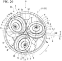
- Figs. 1 and 20 in a front view when the rotating-cutting-edge-type milling tool 1 or 31 is viewed toward the posterior end from the distal end in the tool axial line O direction, when the angle RR is - (minus), the angle RR is a negative radial rake angle, and when the angle RR is + (plus), the angle RR is a positive radial rake angle.
- the cutting edge tangent line L2 when the angle RR is -, gradually extends rearward in the tool rotation direction T as it goes outward in the tool radial direction from the tool distal end edge 5a.
- the cutting edge tangent line L2 when the angle RR is +, gradually extends forward in the tool rotation direction T as it goes outward in the tool radial direction from the tool distal end edge 5a.
- the cutting insert is mounted on the insert attachment seat such that the angle ARt is in the range of the above-described range and the angle RR is in the above-described range so that an effect in which the cutting insert is stably rotated in the driven manner, wear and the like of the rake face are significantly suppressed, and thus a tool life is further increased can be expected.
- the angle RR is out of the above-described range, to be specific, when the angle RR is greater than -30 degrees (and is smaller than -20 degrees), there is a concern that an effect in which the cutting insert can be stably rotated in the driven manner due to a combination of the angle RR and the angle ARt is not easily acquired.
- the angle RR is smaller than -75 degrees, there is a concern that a cutting force at the time of the cutting operation is increased and chatter vibration is easily generated.
- the cutting insert is more stably and easily rotated around the insert axial line in the driven manner with respect to the insert attachment seat by the force received by the cutting edge when the cutting insert cuts into the work material, the above-described effects are more significantly attained.
- the cutting insert is mounted on the insert attachment seat such that angle ARt is in the range of the above-described range and the angle RR is in the above-described range so that an effect in which the cutting insert is stably and easily rotated in the driven manner, wear and the like of the rake face are significantly suppressed, and thus a tool life is further increased can be expected.
- the angle RR is smaller than -20 degrees (and is greater than -30 degrees), there is a concern that an effect in which the cutting insert is stably rotated in the driven manner due to a combination of the angle RR and the angle ARt is not easily acquired.
- the angle RR is greater than 30 degrees, there is a concern that chatter vibration is easily generated or an outer periphery surface (a flank face) of the cutting insert interferes with the work material at the time of the cutting operation, and thus an amount of movement (that is, the feed per revolution fz) of the tool main body per unit rotation around the tool axial line in the tool radial direction is not easily secured.
- a portion on the front surface of the cutting insert which is close to an inside of the cutting edge in an insert radial direction which is orthogonal to the insert axial line, may be formed with a rake face formed a tapered shape which is gradually inclined toward the rear surface from the front surface in the insert axial line direction as it goes inward in the insert radial direction from the cutting edge.
- the cutting insert is mounted on the insert attachment seat in a mounting attitude in which an apparent axial rake angle (an angle AR) is negative.
- an apparent axial rake angle an angle AR
- a substantially axial rake angle is set to be larger in a positive side than the apparent axial rake angle, and the sharpness of the cutting edge is stably increased.
- the cutting insert When the insert axial line extends to be gradually inclined outward in the tool radial direction as it goes forward in the tool rotation direction, the cutting insert is mounted on the insert attachment seat in a mounting attitude in which an apparent radial rake angle (an angle RR) is negative.
- an apparent radial rake angle an angle RR
- a substantially radial rake angle is set to be larger in a positive side than the apparent radial rake angle, and the sharpness of the cutting edge is stably increased.
- the outer periphery surface of the cutting insert may be formed with a flank face formed a tapered shape which is gradually inclined outward in an insert radial direction which is orthogonal to the insert axial line as it goes toward the rear surface from the front surface in the insert axial line direction from the cutting edge.
- the cutting insert may be formed with a through hole which extends on the insert axial line and is open to the front and rear surfaces, a rotating shaft is provided at the insert attachment seat, the rotating shaft including: a shaft potion, a diameter of which is smaller than that of the through hole, which is inserted through in the through hole, and which is attached to the insert attachment seat; and a head potion, a diameter of which is larger than that of the through hole and which has a gap between the head potion and the front surface, wherein a position of the rotating shaft with respect to the insert attachment seat in the insert axial line direction is able to be adjusted, and a restricting potion which is able to restrict movement of the rotating shaft with respect to the insert attachment seat in the insert axial line direction is provided.
- the cutting insert is rotated with respect to the insert attachment seat in the driven manner while being supported by the shaft potion of the rotating shaft (the rotary support body), which is inserted through in the through hole, from an inside in the insert radial direction, and is retained by the head potion of the rotating shaft.
- the position of the rotating shaft with respect to the insert attachment seat in the insert axial line direction is adjusted so that a gap (a clearance) between the head potion of the rotating shaft and the front surface of the cutting insert can be set to a desired value, and the movement of the rotating shaft with respect to the insert attachment seat in the insert axial line direction can be restricted by the restricting potion after the adjustment.
- the rotating shaft can be fixed after a position is minutely adjusted by advancing or retreating the rotating shaft in the insert axial line direction in accordance with a wear (wear and loss) state of the rotating mechanism, and thus the rotation of the cutting insert in the driven manner with respect to the insert attachment seat is more stably maintained.
- the insert attachment seat may include an attachment surface having an axisymmetric geometry centering on the insert axial line.
- the attachment surface of the insert attachment seat has the axisymmetric geometry having the insert axial line as a center (a central axial line)
- the attachment surface is specifically set to, for example, a circular planar shape which is perpendicular to the insert axial line, a conical surface shape having the insert axial line as a central axial line, a spherical shape, or a combined shape of the shapes. Therefore, the entire attachment surface of the insert attachment seat can receive the resultant force, which is transferred to the insert attachment seat from the cutting insert, in a distributed manner, and local wear and the like on the attachment surface is prevented. Thus, the above-described effects are stably acquired over a long period of time.
- a rotating-cutting-edge-type milling tool and a cutting method of the present invention deformation, wear, damage, and the like of a rotary support body such as a rotating shaft of a cutting insert can be prevented, the cutting insert which is mounted on an insert attachment seat can be stably rotated around an insert axial line in a driven manner, and thus processing accuracy of cutting can be stably increased and a tool life can be increased.
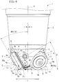
- the rotating-cutting-edge-type milling tool 1 of this embodiment includes a tool main body 2 which is formed of steel or the like and cutting inserts 3 which are formed of a hard material such as cemented carbide, and the discoid cutting inserts 3 are rotatably set and removably mounted around an insert axial line C thereof on insert attachment seats 4 which are formed at an outer periphery portion of a distal end of the tool main body 2 rotating around a tool axial line O.
- Each of the cutting inserts 3 is a so-called round insert having a circular cutting edge 5, and the cutting edge 5 protrudes toward a distal end direction and outward in a radial direction of the tool main body 2 while the cutting insert 3 is mounted on each of the insert attachment seats 4.
- a posterior end of the tool main body 2 is attached to a main shaft of a machine tool (not shown), is rotated in a tool rotation direction T of around the tool axial line O, and is used for a cutting operation (in particular, a heavy cutting operation) of a work material such as a hard-to-cut material such as a heat resistant alloy.
- the rotating-cutting-edge-type milling tool 1 is a rotary milling tool in which the cutting insert 3 is rotated around the insert axial line C in a driven (passive) manner with respect to the insert attachment seat 4 by force received by the cutting edge 5 (which is cutting force or cutting resistance and includes cutting edge force or a component of edge force) when the cutting insert 3 cuts into the work material.
- the insert attachment seat 4 side of the tool main body 2 in a tool axial line O direction is referred to as a direction toward a tool distal end or simply a distal end direction (a lower side of Figs. 2 to 6 ), and an opposite side (a main shaft side of the machine tool) to the insert attachment seat 4 in the tool axial line O direction is referred to as a direction toward a tool posterior end or simply a posterior end direction (an upper side of Figs. 2 to 6 ).
- a direction which is perpendicular to the tool axial line O is referred to as a tool radial direction
- a direction around the tool axial line O is referred to as a tool circumferential direction.
- a direction in which the tool main body 2 is rotated at a time of cutting is referred to as the tool rotation direction T or the forward in the tool rotation direction T, and a direction toward an opposite side to the tool rotation direction T (the forward thereof) is referred to as the rearward in the tool rotation direction T.
- a direction which is perpendicular to the insert axial line C of the cutting insert 3 is referred to as an insert radial direction, and a direction around the insert axial line C is referred to as the insert circumferential direction.
- the tool main body 2 has a cylindrical shape or a disk shape and can be rotated around the tool axial line O serving as a central axial line thereof.
- the tool main body 2 has the cylindrical shape, and is formed to have a portion (a shank potion) other than a distal end potion (a blade potion) in the tool main body 2, a diameter of which is greater than that of the distal end potion.
- a diameter of the distal end potion of the tool main body 2 is gradually reduced toward the tool distal end, and the distal end potion thereof has a tapered shape.
- the distal end outer periphery portion of the tool main body 2 is formed with a plurality of chip pockets 6 to be cut in a concave shape from the distal end outer periphery portion at intervals in the tool circumferential direction.
- a wall surface of each of the chip pockets 6, which faces the tool rotation direction T, is formed with the insert attachment seat 4 on which the cutting insert 3 is removably mounted.
- the insert attachment seats 4 are formed with attachment surfaces 4a which face the tool rotation direction T, restricting surfaces 4b which each rise from circumferential edge portions of the attachment surfaces 4a, rotary shaft mounting holes 4c which are each drilled in the attachment surfaces 4a, and a coolant hole (not shown) which ejects a coolant (cutting oil) between the insert attachment seat 4 and the cutting insert 3.
- a sheet-shaped thrust sliding bearing member (a rotating mechanism) 8 which is located between the cutting insert 3 and the attachment surface 4a is provided at the insert attachment seat 4.
- the attachment surface 4a is formed in a substantially circular planar shape to correspond to a shape of the cutting insert 3.
- the attachment surface 4a has an axisymmetric geometry centering on the insert axial line C.
- the "axisymmetric geometry" described in this specification includes a constitution with a strictly axisymmetric geometry and a constitution with a roughly axial symmetric shape.
- the restricting surface 4b is a planar wall surface, which rises forward in the tool rotation direction T from a posterior end edge on the attachment surface 4a of the tool main body 2 and faces the tool distal end direction.
- the restricting surface 4b extends linearly when the attachment surface 4a of the insert attachment seat 4 is viewed from the front.
- the rotary shaft mounting holes 4c has a multi-stage cylindrical hole shape, and an inner diameter of an end portion (an opening) of the rotary shaft mounting hole 4c, which is open in the attachment surface 4a, is one step greater than an inner diameter of a portion other than the opening.
- the portion other than the opening in the rotary shaft mounting hole 4c is a female threaded potion on which a female threading process is performed.
- a portion of the distal end potion of the tool main body 2, which is between the insert attachment seats 4 adjacent to each other in the tool circumferential direction, is open in an outer periphery surface of the distal end potion thereof, and is formed with a screw hole 7 which is in communication with an inside of the rotary shaft mounting hole 4c extending in the tool radial direction.
- the coolant hole is in communication with the main shaft of the machine tool which is mounted on the posterior end of the tool main body 2 via an inside of the tool main body 2.
- a central axial line of the coolant hole extends in the insert circumferential direction of the cutting insert 3 (in a tangent line direction in the insert circumferential direction), and a direction of the coolant ejected from the coolant hole which is open in the attachment surface 4a is set to a direction in which the cutting insert 3 with respect to the insert attachment seat 4 is rotated in a driven manner.
- the thrust sliding bearing member (a sliding bearing member) 8 has a discoid shape, and a hole 8a, through which the thrust sliding bearing member 8 can pass, is open in centers of a pair of circular surfaces which face a thickness direction thereof (a central axial line direction of the thrust sliding bearing member 8). Also, a portion of an outer periphery surface of the thrust sliding bearing member 8 is formed with a cutout potion 8b which is cut linearly when the thrust sliding bearing member 8 is viewed from the front in a thickness direction thereof.
- the thrust sliding bearing member 8 is formed with a coolant flow hole 8c through which the thrust sliding bearing member 8 passes in the thickness direction.
- one circular surface 8d, on which the cutting insert 3 sits, among a pair of circular surfaces of the thrust sliding bearing member 8, which face a thickness direction thereof, is an attachment surface in the insert attachment seat 4.
- a rear surface 10 of the cutting insert 3 (a surface which faces the rearward in the tool rotation direction T) sits on the one circular surface (an attachment surface) 8d of the thrust sliding bearing member 8 of the insert attachment seat 4, which faces the forward in the tool rotation direction T.
- the one circular surface 8d has an axisymmetric geometry centering on the insert axial line C.
- the hole 8a is in communication with the rotary shaft mounting hole 4c, and the coolant flow hole 8c is in communication with the coolant hole in a state in which the thrust sliding bearing member 8 is arranged on the attachment surface 4a.
- the cutout potion 8b can be arranged opposite to the restricting surface 4b and locked. Thus, rotation of the thrust sliding bearing member 8 with respect to the attachment surface 4a in the insert circumferential direction is restricted.
- the cutting insert 3 is more easily rotated in a driven manner in a predetermined insert circumferential direction by bringing the coolant, which is ejected via the coolant flow hole 8c from the coolant hole, into contact with a seating surface 13 of the cutting insert 3 using only the force received by the cutting edge 5 (which is the cutting force or cutting resistance and includes the cutting edge force or the component of edge force) when the cutting insert 3 cuts into the work material at the time of cutting, instead of rotating the cutting insert 3 with respect to the insert attachment seat 4 in a driven manner.
- a thrust rolling bearing member (a rolling bearing member) may be provided at the insert attachment seat 4 instead of the thrust sliding bearing member 8.
- the rear surface 10 of the cutting insert 3 sits on an attachment surface of the thrust rolling bearing member of the insert attachment seat 4, which faces the forward in the tool rotation direction T.
- the rear surface 10 of the cutting insert 3 may directly sit on the attachment surface 4a of the tool main body 2.
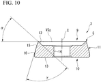
- the cutting insert 3 has front and rear surfaces 9 and 10 which intersect the insert axial line C (which are substantially orthogonal to the insert axial line C) and an outer periphery surface 11 which connects circumferential edges of the front and rear surfaces 9 and 10.
- the "front and rear surfaces 9 and 10 which intersect the insert axial line C" described in this specification refers to a state in which the insert axial line C is located inside a through hole 14 to be described below which is open to pass through the front and rear surfaces 9 and 10 and the insert axial line C passes through centers (virtual centers) of the front and rear surfaces 9 and 10.
- the outer periphery surface 11 extends in the insert axial line C direction and connects the circumferential edges of the front and rear surfaces 9 and 10.
- the front surface 9 among the front and rear surfaces 9 and 10 is located to face the forward in the tool rotation direction T
- the rear surface 10 is located to face the rearward in the tool rotation direction T
- the cutting insert 3 sits on the insert attachment seat 4 (the thrust sliding bearing member 8 of the insert attachment seat 4 in this embodiment) in a state in which the cutting insert 3 is mounted on the insert attachment seat 4 of the tool main body 2.
- a circumferential edge of the front surface 9 is formed with the cutting edge 5 having a circular shape which extends in the insert circumferential direction and located on a cutting edge virtual plane VS 0 which is orthogonal to the insert axial line C, and the cutting edge 5 protrudes more in the insert axial line C direction than a portion other than the cutting edge 5 in the front surface 9.
- an inside of the front surface 9 in the insert radial direction of the cutting edge 5 is formed with a tapered rake face 12 which is gradually inclined toward the rear surface 10 from the front surface 9 in the insert axial line C direction it goes inward in the insert radial direction from the cutting edge 5.
- a direction in the insert axial line C direction, which is directed toward the rear surface 10 from the front surface 9 is simply referred to as the rear surface 10 direction in the insert axial line C direction in some cases.
- a direction in the insert axial line C direction, which is directed toward the front surface 9 from the rear surface 10 is simply referred to as the front surface 9 direction in the insert axial line C direction.
- an angle ⁇ at which the rake face 12 is inclined with respect to the cutting edge virtual plane VS 0 is in a range of, for example, 35 degrees to 50 degrees.
- a portion other than the cutting edge 5 and the rake face 12 in the front surface 9 has a planar shape which is perpendicular to the insert axial line C.
- An outer periphery edge portion of the rear surface 10 is recessed one step compared to a portion other than the outer periphery edge portion thereof.
- a portion other than the outer periphery edge portion in the rear surface 10 is the seating surface 13 which sits on an attachment surface (the circular surface 8d of the thrust sliding bearing member 8 in this embodiment) of the insert attachment seat 4.
- the seating surface 13 has a planar shape which is perpendicular to the insert axial line C to correspond to the attachment surface of the insert attachment seat 4 having a planar shape which is perpendicular to the insert axial line C.
- the cutting insert 3 is formed with the through hole 14 which extends on the insert axial line C and is open to pass through the front and rear surfaces 9 and 10.
- diameters of both end portions of the through hole 14 in the insert axial line C direction are greater than that of a portion other than both end portions.
- a portion other than both end portions in the through hole 14 has a substantially constant inner diameter over the entire insert axial line C direction.
- the outer periphery surface 11 of the cutting insert 3 is formed with a tapered flank face 15 which is gradually inclined outward in the insert radial direction as it goes toward the rear surface 10 from the front surface 9 in the insert axial line C direction from the cutting edge 5 which forms an outer periphery end edge of the front surface 9.
- an angle ⁇ at which the flank face 15 is inclined with respect to the insert axial line C is in a range of, for example, 10 degrees to 35 degrees.
- the amount of displacement of the body clearance 16 is smaller than an amount of displacement in the insert radial direction per unit length of the flank face 15 in the insert axial line C direction.
- an end portion of the outer periphery surface 11, which is in the rear surface 10 direction in the insert axial line C direction has a cylindrical surface shape centering on the insert axial line C.
- a wedge angle ⁇ centering on the cutting edge 5 formed between the rake face 12 and the flank face 15 is in a range of, for example, 65 degrees to 75 degrees when viewed in the longitudinal cross section shown in Fig. 10 .
- the rotating-cutting-edge-type milling tool 1 includes a rotating shaft (a rotary support body) 17 and a restricting potion as a clamping mechanism of a cutting insert configured to rotatably mount the cutting insert 3 on the insert attachment seat 4.
- the rotating shaft 17 has a shaft potion 17a, a diameter of which is smaller than that of the through hole 14 of the cutting insert 3 and the hole 8a of the thrust sliding bearing member 8, and which is inserted through in the through hole 14 and the hole 8a and is attached to the insert attachment seat 4 and a head potion 17b, a diameter of which is larger than that of the through hole 14 and which is located to have a gap between the head potion 17b and the front surface 9.
- An end portion of the shaft potion 17a which is opposite to the head potion 17b, is a male screw potion, a diameter of which is smaller than that of a portion other than the end portion, and on which a male threading process is performed.
- the male screw potion of the shaft potion 17a is screwed into a female threaded potion of the rotary shaft mounting hole 4c so that the rotating shaft 17 is removably mounted on the insert attachment seat 4, and the amount of screwing of the male screw potion with respect to the female threaded potion is adjusted so that a position of the rotating shaft 17 with respect to the insert attachment seat 4 in the insert axial line C direction can be adjusted.
- a set screw 18 is screwed into the screw hole 7 of the tool main body 2, and a tip of the set screw 18 is brought into contact with the shaft potion 17a of the rotating shaft 17 so that movement of the rotating shaft 17 with respect to the insert attachment seat 4 in the insert axial line C direction can be restricted, and the restricting potion having the screw hole 7 and the set screw 18 is configured.
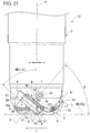
- the tip of the set screw 18 is in contact with a portion other than the male screw potion in the shaft potion 17a (refer to Fig. 24 ).
- the insert axial line C of the cutting insert 3 extends to be gradually inclined toward the tool distal end as it goes forward in the tool rotation direction T in a state in which the cutting insert 3 is mounted on the insert attachment seat 4.
- the present invention is not limited thereto, and the insert axial line C of the cutting insert 3 may extend to be gradually inclined outward in the tool radial direction as it goes forward in the tool rotation direction T.
- the insert axial line C of the cutting insert 3 may extend to be gradually inclined forward in the tool rotation direction T and outward in the tool radial direction as it goes forward in the tool rotation direction T.
- an inclined direction of the insert axial line C is determined by setting a representative cutting point as will be described below.
- the inclined direction of the insert axial line C is not uniquely determined by determining the representative cutting point, but is determined in consideration of for example, an inclined direction or the like, in which the cutting insert 3 is more easily rotated in a driven manner, as well.
- a component of force at the representative cutting point in the principal force direction is a principal force F1
- a component of force which is perpendicular to the principal force direction and is directed in a back force direction is a back force F2.
- An extending direction of the insert axial line C is set parallel or to have a predetermined minute angle (that is, set substantially parallel) to a direction of a resultant force F3 of the principal force F1 and the back force F2 on a surface of the first virtual plane VS 1 shown as a cross-sectional view in Fig. 13 .
- force indicated by reference numeral F4 in Fig. 13 is a component of force (that is, a component of force which passes through the representative cutting point, and a direction of which is orthogonal to the first virtual plane VS 1 ) is directed in a direction of the tangent line L2 which passes through the representative cutting point of the cutting edge 5, and the component of force is referred to as a feed force F4 in this specification.
- the feed force F4 is set outward in the tool radial direction.
- the force received by the cutting insert 3 when the cutting edge 5 of the cutting insert 3 mounted on the tool main body 2 cuts into the work material at the time of the cutting operation is a distributed load which is distributed to an entire contact area (in general, chips are substantially discharged from a cut-in region in a central direction of the cutting insert 3 while coming into contact with the rake face 12) of the rake face 12 and the work material/chips including the cut-in region (a hatched region of Fig. 12 ; which is also referred to as a "cut cross section") of the cutting insert 3, which cuts into the work material.
- the distributed load is regarded (assumed) as a concentrated load on the basis of the force and a moment (a moment viewed from an insert center) received by the cutting insert 3 due to the distributed load
- the point of intersection of the predetermined insert radial direction ID passing through the point of action (a point corresponding to a center of gravity of the distributed load) P of the concentrated load and the cutting edge 5 is referred to as the "representative cutting point" in this specification.
- the point of action of the concentrated load when the distributed load which acts on the cutting insert 3 from the work material at the time of the cutting operation is regarded as the concentrated load is indicated as reference numeral P
- the point of intersection 5c of the predetermined insert radial direction ID passing through the point of action P and the circular cutting edge 5 is the representative cutting point.
- the representative cutting point can be said to be a point on the cutting edge 5, which is closest to a point of average action of the cutting force at the time of the cutting operation.
- the representative cutting point is located on the cutting edge 5 of the cutting insert 3.
- the representative cutting point is not rotated together with the cutting insert 3, and a relative position thereof with respect to the tool is not changed. Note that, since the point of action P of the force is changed, for example, when the depth of cut in the tool axial line O direction is changed, the representative cutting point is moved with it.
- the "instantaneous cutting direction at the representative cutting point” is a direction of a relative instantaneous speed in the representative cutting point between the tool and the work material and is mainly rotated along with rotation of the tool.
- an amount depending on the feed per tooth is indicated as reference numeral f in Fig. 12 , and after the tool main body 2 of the rotating-cutting-edge-type milling tool 1 is fed in the tool radial direction so that the cutting edge 5 (the cutting edge 5 indicated by an alternating long and two short dashes line) of the cutting insert 3, which is in the forward in the tool rotation direction T, cuts the work material, a separate (current) cutting edge 5 (the cutting edge 5 indicated by a solid line) of the cutting insert 3, which is in the rearward in the tool rotation direction T of the cutting edge 5, cuts the hatched region of Fig. 12 .
- the "amount f depending on the feed per tooth" is different from a generally called feed per revolution fz, and also depends on a tool rotation position and an attachment angle of the insert axial line C.
- the representative cutting point is set at a predetermined position in an arc-shaped portion with a central angle of 90 degrees (an arc of 1/4 when a circumference of the cutting edge 5 is set to 1) between a portion (a tool distal end edge 5a) located at a distal end in the tool axial line O direction and a portion (a tool outer diameter edge 5b) located at an outer end in the tool radial direction, which is in an entire circumference of the cutting edge 5 of the cutting insert 3 mounted on the tool main body 2.
- the representative cutting point on the cutting edge 5 is near the tool distal end edge 5a.
- the desired type of the cutting operation is a "shoulder milling process” or the like
- the representative cutting point on the cutting edge 5 is near the tool outer diameter edge 5b.
- the desired type of the cutting operation is an "R milling process” or the like serving as a combination process of the face milling process and the shoulder milling process
- the representative cutting point on the cutting edge 5 is an intermediate point 5c which is between the tool distal end edge 5a and the tool outer diameter edge 5b.
- the representative cutting point is at a predetermined position (a predetermined range) on the cutting edge 5, which can be predetermined in advance by an expected cutting operation, and an inclination of the insert axial line C is set substantially parallel to the direction of the resultant force F3 of the principal force F1 and the back force F2 at the representative cutting point in this embodiment.
- the expression "extending direction of the insert axial line C is set parallel or to have the predetermined minute angle (that is, set to be parallel) to the direction of the resultant force F3 of the principal force F1 and the back force F2 on the surface of the first virtual plane VS 1 " described in this specification specifically means that an angle at which the insert axial line C is inclined with respect to the direction of the resultant force F3 is in a range of ⁇ 20 degrees on the surface of the first virtual plane VS 1 (when viewed in the direction of the tangent line L2 of the cutting edge 5 passing through the representative cutting point) in a range of a cutting condition which can be assumed using the rotating-cutting-edge-type milling tool 1.
- the angle formed by two straight lines such as the insert axial line C and the direction of the resultant force F3 is in the range of ⁇ 20 degrees, which indicates the expression "set parallel or to have the predetermined minute angle.”
- the angle is preferably ⁇ 10 degrees and the angle is more preferably ⁇ 5 degrees.
- the insert axial line C is parallel (set parallel) to the direction of the resultant force F3.
- the above-described angle at which the insert axial line C is inclined with respect to the direction of the resultant force F3 is in the range of ⁇ 20 degrees means that the angle formed by the direction of the resultant force F3 and the insert axial line C is 20 degrees or less. Also, the above-described angle at which the insert axial line C is inclined with respect to the direction of the resultant force F3 is in a range of ⁇ 10 degrees means that the angle formed by the direction of the resultant force F3 and the insert axial line C is 10 degrees or less.
- the above-described angle at which the insert axial line C is inclined with respect to the direction of the resultant force F3 is in a range of ⁇ 5 degrees means that the angle formed by the direction of the resultant force F3 and the insert axial line C is 5 degrees or less.
- the extending direction of the insert axial line C with respect to the direction of the resultant force F3 is not limited to only "parallel” and is set to have a slight angular range because the following reasons.
- the direction of the resultant force F3 is changed by, for example, a shape of the rake face 12 of the cutting insert 3, a cutting edge process and a wear state of the cutting edge 5, a coefficient of friction of the work material, a cutting condition (the deps of cut, the feed, or the like), or the like.
- the expression "set parallel or to have the predetermined minute angle" is used as a range in which an effect of the present invention can be sufficiently acquired.
- the resultant force F3 and the insert axial line C are substantially parallel to each other, and an example in which the representative cutting point on the cutting edge 5 is set at the tool distal end edge 5a is used.
- Figs. 3 and 4 are views when viewed in the direction of the tangent line L2 which passes through the tool distal end edge 5a (the representative cutting point of this embodiment) of the cutting edge 5 of the cutting insert 3 shown in Fig. 1 , and the direction of the resultant force F3 of the principal force F1 and the back force F2 is set parallel or to have a predetermined minute angle to the insert axial line C (on the surface of the first virtual plane VS 1 which is perpendicular to the tangent line L2) when viewed in the direction of the tangent line L2.
- a machined surface of the work material, which is cut by the rotating-cutting-edge-type milling tool 1, is indicated by reference numeral MS in Fig. 4 .
- the machined surface MS described in this specification is a virtual plane (that is the above-described second virtual plane VS 2 ) including the tangent line L2 passing through the representative cutting point of the cutting edge 5 and a virtual straight line (a tangent line of a virtual circle VC indicated by reference numeral L1 of Fig. 1 ) in an instantaneous cutting direction at the representative cutting point, and is a virtual component element (a concept), in which a minute range including the representative cutting point spreads and is indicated in a planar shape and which is used showing the present invention, on a concave curved surface which is actually processed by the discoid cutting insert 3.
- an angle (an angle of inclination) ⁇ at which the insert axial line C is inclined with respect to the machined surface MS (the second virtual plane VS 2 ) is in a range of, for example, 20 degrees to 70 degrees when viewed in the direction the tangent line L2 shown in Fig. 4 .
- a reference is provided by determining the inclination of the insert axial line C in accordance with the direction of the resultant force F3 set in accordance with a desired cutting operation condition, and a slight allowable width (a positive or negative angular range) is preferably provided to an angle serving as the reference.
- an angle ⁇ is preferably in a range of 45 degrees ⁇ 20 degrees, and more preferably in a range of 45 degrees ⁇ 5 degrees (for example, refer to a range of an angle ARn (an angle range corresponding to the angle ⁇ when the representative cutting point of the cutting edge 5 is on the tool distal end edge 5a) shown in a graph of Fig. 17 ).
- Figs. 5 and 6 are cross sections taken along line E-E, which is viewed from a predetermined tool radial direction D passing through the tool distal end edge 5a of the cutting edge 5, in the tool radial direction of the rotating-cutting-edge-type milling tool 1 shown in Fig. 1 .
- a circle obtained by a locus when the tool distal end edge 5a (the representative cutting point) on the cutting edge 5, is rotated the tool circumferential direction is set as a virtual circle VC.
- an angle ARt at which a cross line CL of the reference plane SS and the cutting edge virtual plane VS 0 including the circular cutting edge 5 is inclined with respect to the tool axial line O projected onto the reference plane SS is in a range of, for example, -30 degrees to -60 degrees.
- the angle ARt is an axial rake angle in which the instantaneous cutting direction in the tool distal end edge 5a of the cutting edge 5 used for cutting is considered, and is specifically a negative axial rake angle.
- the angle ARt is - (minus), the angle ARt is the negative axial rake angle, and if the angle ARt is + (plus), the angle ARt is a positive axial rake angle when viewed in the longitudinal cross section including the reference plane SS shown in Fig. 6 .
- the angle ARt when the angle ARt is -, the cross line CL gradually extends forward in the tool rotation direction T as it goes toward the tool posterior end from the tool distal end edge 5a.
- the angle ARt is +, the cross line CL gradually extends rearward in the tool rotation direction T as it goes toward the tool posterior end from the tool distal end edge 5a.
- the reference surface is a virtual plane which is perpendicular to the instantaneous cutting direction in the tool distal end edge 5a of the cutting edge 5.
- an angle ARn at which the cutting edge virtual plane VS 0 is inclined with respect to the tool axial line O is in a range of, for example, -30 degrees to -50 degrees when viewed in the tool radial direction which is perpendicular to the cutting edge virtual plane VS 0 .
- the angle ARn is an axial rake angle in which the instantaneous cutting direction of the cutting insert 3 alone which is mounted on the tool main body 2 is not considered, and a negative axial rake angle.
- the angle ARn when the angle ARn is - (minus), the angle ARn is the negative axial rake angle, and when the angle ARn is + (plus), the angle ARn is a positive axial rake angle when the rotating-cutting-edge-type milling tool 1 is viewed inward in the tool radial direction and when viewed from the side which is perpendicular to the cutting edge virtual plane VS 0 .
- the angle ARn when the angle ARn is -, the cutting edge virtual plane VS 0 gradually extends forward in the tool rotation direction T as it goes toward the tool posterior end from the tool distal end edge 5a.
- the cutting edge virtual plane VS 0 gradually extends rearward in the tool rotation direction T as it goes toward the tool posterior end from the tool distal end edge 5a.
- an angle of inclination ⁇ formed by the machined surface MS (the second virtual plane VS 2 ) and the insert axial line C is the same as ARn which is described above.
- the angle ARt and the angle ARn are angles in which a shape of the rake face 12, which is adjacent to the cutting edge 5 of the cutting insert 3, is not considered, the angle ARt and the angle ARn can be said to be the apparent axial rake angle.
- the angle ARt is set to 45 degrees of negative (-45 degrees) and the angle ARn is set to 30 degrees of negative (-30 degrees).
- an angle RR at which a cutting edge tangent line L2 of the cutting edge 5 which passes through the tool distal end edge 5a and extends outward in the tool radial direction, is inclined with respect to a predetermined tool radial direction D among the tool radial directions which passes through the tool distal end edge 5a, is in a range of, for example, -30 degrees to -75 degrees.
- the angle RR is a radial rake angle at the tool distal end edge 5a of the cutting edge 5 used for cutting and is specifically a negative radial rake angle.
- the angle RR is 55 degrees of negative (-55 degrees). As shown in Fig.
- the cutting edge tangent line L2 gradually extends forward in the tool rotation direction T as it goes outward in the tool radial direction from the tool distal end edge 5a (refer to Fig. 20 ).
- Fig. 11 is a view in which angles such as the angles ARt, ARn, and RR which are described above are simplified.
- Fig. 13 is a simplified diagram showing that the direction of the resultant force F3 of the principal force F1 and the back force F2 and the extending direction of the insert axial line C, which are described above, are substantially parallel to each other.
- the tool distal end edge 5a is the representative cutting point on the cutting edge 5 in Fig. 13
- the tool outer diameter edge 5b on the cutting edge 5 or the intermediate point 5c between the tool distal end edge 5a and the tool outer diameter edge 5b may be the representative cutting point (with regard to positions of the tool outer diameter edge 5b and the intermediate point 5c on the circumference of the cutting edge 5, refer to Figs. 1 and 4 ).
- the present invention is not limited to the constitution of the rotating-cutting-edge-type milling tool 1 used for describing this embodiment.
- the machined surface MS (the second virtual plane VS 2 ), in which the tool distal end edge 5a is set as the reference, is perpendicular to the tool axial line O, and the insert axial line C of the cutting insert 3 is substantially on a virtual plane which is perpendicular to the machined surface MS (the second virtual plane VS 2 ).
- the machined surface MS (the second virtual plane VS 2 ), in which the tool outer diameter edge 5b is set as the reference, is parallel to the tool axial line O, and the insert axial line C of the cutting insert 3 is substantially on the virtual plane which is perpendicular to the machined surface MS (the second virtual plane VS 2 ).
- the machined surface MS (the second virtual plane VS 2 ), in which the intermediate point 5c is set as the reference, is an inclined surface which is not perpendicular or parallel to the tool axial line O, and the insert axial line C of the cutting insert 3 is substantially on the virtual plane which is perpendicular to the machined surface MS (the second virtual plane VS 2 ).
- Figs. 14A to 16 are views in which the representative cutting point of the cutting insert 3 and the machined surface MS (the second virtual plane VS 2 ), in which the representative cutting point is set as the reference, are simplified.
- Figs. 14A and 14B show a case in which the representative cutting point of the cutting insert 3 is set at the tool distal end edge 5a
- reference numeral i shown in the drawings indicates an angle of inclination of the cutting on the machined surface MS (the second virtual plane VS 2 ) serving as the virtual plane including the two straight lines at the tool distal end edge 5a such as the virtual straight line L1 (the tangent line L1 passing through the tool distal end edge 5a of the virtual circle VC serving as a rotational locus of the tool distal end edge 5a in the tool rotation direction T) in the instantaneous cutting direction and the tangent line L2 which passes through the tool distal end edge 5a of the cutting edge 5.
- the machined surface MS (the second virtual plane VS 2 ) is the virtual plane which is perpendicular to the tool axial line O.
- an angle of inclination i of the cutting is an angle which is formed by a normal NL which is perpendicular to the tangent line L2 passing through the representative cutting point (the tool distal end edge 5a in Figs. 14A and 14B ) of the cutting edge 5 and the virtual straight line L1 (the tangent line L1) which extends in the instantaneous cutting direction of the representative cutting point on the machined surface MS (the second virtual plane VS 2 ).
- the tangent line L1 is a tangent line which passes through the tool distal end edge 5a of the virtual circle VC serving as the rotational locus formed when the tool distal end edge 5a serving as the representative cutting point of the cutting edge 5 is rotated around the tool axial line O.
- Fig. 15 shows a case in which the representative cutting point of the cutting insert 3 is set at the intermediate point 5c.
- a virtual circle VC serving as the rotational locus formed when the intermediate point 5c is rotated around the tool axial line O is located closer to the tool posterior end direction than the virtual circle VC when the above-described representative cutting point is set at the tool distal end edge 5a, and a diameter thereof is greater than the virtual circle VC.
- the machined surface MS (the second virtual plane VS 2 ) serving as the virtual plane including the two straight lines such as the virtual straight line L1 (the tangent line L1 passing through the intermediate point 5c of the virtual circle VC) in the instantaneous cutting direction and the tangent line L2 which passes through the intermediate point 5c of the cutting edge 5 at the intermediate point 5c is an inclined surface which is not perpendicular or parallel to the tool axial line O.
- the angle of inclination i of the cutting in Fig. 15 is the angle which is formed by the normal NL which is perpendicular to the tangent line L2 passing through the representative cutting point (the intermediate point 5c in Fig. 15 ) of the cutting edge 5 and the virtual straight line L1 (the tangent line L1) which extends in the instantaneous cutting direction of the representative cutting point on the machined surface MS (the second virtual plane VS 2 ).
- the tangent line L1 in this case is a tangent line which passes through the intermediate point 5c of the virtual circle VC serving as the rotational locus formed when the intermediate point 5c serving as the representative cutting point of the cutting edge 5 is rotated around the tool axial line O.
- the machined surface MS (the second virtual plane VS 2 ) is the virtual plane which is parallel to the tool axial line O
- the angle of inclination i of the cutting is the angle which is formed by the normal NL which is perpendicular to the tangent line L2 passing through the representative cutting point (the tool outer diameter edge 5b) of the cutting edge 5 and the virtual straight line L1 (the tangent line L1) which extends in the instantaneous cutting direction of the representative cutting point on the machined surface MS (the second virtual plane VS 2 ).
- the inventors of the present invention found that the cutting insert 3 is stably and easily rotated in the driven manner when the angle of inclination i of the cutting is in a range of i ⁇ -15 degrees or 15 degrees ⁇ i and satisfies the conditions of the present invention (in which the insert axial line C is substantially parallel to the direction of the resultant force F3 on the surface of the first virtual plane VS 1 ) on the basis of an experimental result, a simulation (an analysis), and the like.
- cutting insert 3 is stably rotated in the driven manner described in this specification means that the cutting insert 3 continues to be even slightly rotated around the insert axial line C every time the cutting insert 3 cuts into the work material during the cutting operation.
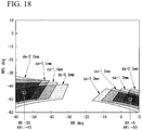
- the angle ARn shown in the graph corresponds to the angle ⁇ (the angle which is set substantially parallel to the insert axial line C with respect to the direction of the resultant force F3) at which the insert axial line C is inclined with respect to the machined surface MS (the second virtual plane VS 2 ) and is 45 degrees ⁇ 5 degrees in the illustrated example. Also, since the angle of inclination i of the cutting used to stably rotate the cutting insert 3 in the driven manner is in the range of i ⁇ -15 degrees or 15 degrees ⁇ i, the ranges of the angles ARt and RR are determined by the combination thereof (a region in which the angle ranges overlap each other).
- Fig. 18 shows a graph in which the ranges of the angles ARt and RR when various representative cutting points are set in accordance with a depth of cut da on the basis of this concept are acquired.
- the combination of the angle ARt: -45 degrees and the angle RR: -55 degrees, which is described in this embodiment, is in a range in which the cutting insert 3 is stably rotated in the driven manner irrespective of a magnitude of the depth of cut da (specifically, at at least da which is in a range of 0.5 to 2.0 mm).
- a pair of circular surfaces including the attachment surface 4a of the insert attachment seat 4 on which the cutting insert 3 is mounted and the one circular surface (the attachment surface) 8d of the thrust sliding bearing member 8 both have planar shapes which are perpendicular to the insert axial line C.
- an attachment surface of the insert attachment seat 4 has an axisymmetric geometry centering on the insert axial line C.
- a rotating shaft (a rotary support body) 17 which is on the insert axial line C of the cutting insert 3 is sufficiently suppressed from being pressed by the resultant force F3 in the insert radial direction (that is, in a shear direction of the rotating shaft 17), and the resultant force F3 can be sufficiently released to the insert attachment seat 4 via the rear surface 10 of the cutting insert 3.
- deformation, wear, damage, and the like of the rotating shaft 17 of the cutting insert 3 are prevented.
- the inclination of the insert axial line C is determined in advance so as to be in parallel with the direction of the resultant force F3 acting on the representative cutting point on the cutting edge 5, which is determined in accordance with a desired cutting operation (a predetermined cutting condition and the like) using the rotating-cutting-edge-type milling tool 1, from the work material at the time of the cutting operation so that a load of the cutting insert 3 with respect to the rotating shaft 17 can be stably and significantly reduced.
- the cutting insert 3 Since the rotating shaft 17 of the cutting insert 3 is not easily pressed in the insert radial direction, the cutting insert 3 is stably rotated around the insert axial line C in the driven manner with respect to the insert attachment seat 4 by the force received by the cutting edge 5 when the cutting insert 3 cuts into the work material.
- the rotating shaft 17 is used as the rotary support body of the cutting insert 3 in this embodiment, but the present invention is not limited thereto.
- a radial bearing including a radial slide bearing
- the radial bearing is suppressed from being pressed by the resultant force F3 in the insert radial direction, and deformation, wear, damage, occurrence of excessive friction torque, and the like of the radial bearing are prevented.
- occurrence of excessive friction torque is prevented means preventing a phenomenon in which friction torque is too large and thus the cutting insert 3 is not easily rotated when the cutting insert 3 is rotatably supported by the rotary support body such as the radial bearing from the outside in the insert radial direction as described above.
- the representative cutting point is set at the tool distal end edge 5a on the cutting edge 5.
- the insert axial line C extends to be gradually inclined toward the tool distal end (that is, inclined forward) as it goes forward in the tool rotation direction T.
- a space in which a rotating mechanism (the thrust sliding bearing member 8 of this embodiment) configured to rotate the cutting insert 3 in the driven manner is arranged in the insert attachment seat 4 can be easily secured.
- the insert axial line C is inclined forward as described above so that, even if an interval between the adjacent insert attachment seats 4 in the tool circumferential direction tends to be narrow in the multi-blade rotating-cutting-edge-type milling tool 1, in which a plurality of cutting inserts 3 are mounted, the space in which the rotating mechanism is arranged can be easily secured as in this embodiment.
- the insert axial line C extends to be gradually inclined outward in the tool radial direction as it goes forward in the tool rotation direction T.
- the insert axial line C may extend to be gradually inclined toward the tool distal end and outward in the tool radial direction as it goes forward in the tool rotation direction T. Even in these cases, the space can also be easily secured between the insert attachment seats 4 in the tool circumferential direction.
- the representative cutting point of the cutting edge 5 of the cutting insert 3 is set at a predetermined position in the arc-shaped portion with the central angle of 90 degrees between the portion (the tool distal end edge 5a) located at the distal end in the tool axial line O direction and the portion (the tool outer diameter edge 5b) located at the outer end in the tool radial direction which is orthogonal to the tool axial line O, which is in the entire circumference of the cutting edge 5.
- the representative cutting point on the cutting edge 5 is close to the tool distal end edge 5a. Also, if the type of the cutting operation is the "shoulder milling process,” the representative cutting point on the cutting edge 5 is close to the tool outer diameter edge 5b.
- the present invention can be applied to the rotating-cutting-edge-type milling tool 1 used for, for example, the face milling process, the shoulder milling process, the combination process thereof (the R milling process), and the like.
- the cutting insert 3 is stably and easily rotated around the insert axial line C in the driven manner with respect to the insert attachment seat 4 by the force received by the cutting edge 5 when the cutting insert 3 cuts into the work material, and the above-described effects are significantly attained.
- the angles ARt and RR of this embodiment are derived on the basis of the graph of Fig. 18 .
- the cutting insert 3 is mounted on the insert attachment seat 4 to fall in the range of the angle ARt and the range of the angle RR which are described above so that it can be expected that the cutting insert 3 can be stably rotated in the driven manner, the wear and the like of the rake face 12 is significantly suppressed, and the life is further increased.
- the angle RR is out of the above-described range, to be specific, when the angle RR is greater than -30 degrees (and is smaller than -20 degrees), there is a concern that an effect in which the cutting insert 3 can be stably rotated in the driven manner due to a combination of the angle RR and the angle ARt is not easily acquired.
- the angle RR is smaller than -75 degrees, there is a concern that a cutting force at the time of the cutting operation is increased and chatter vibration is easily generated.
- the insert axial line C may extend to be gradually inclined outward in the tool radial direction as it goes forward in the tool rotation direction T.
- the cutting insert 3 is mounted on the insert attachment seat 4 in the mounting attitude in which the radial rake angle (the angle RR) in external appearance is negative.
- a substantially radial rake angle is set to be larger in a positive side than the apparent radial rake angle, and the sharpness of the cutting edge 5 is also stably increased.
- the angle ⁇ is less than 35 degrees, there is a concern that the cutting edge is less likely to become sharp enough as the sharpness of the cutting edge 5 is sufficiently increased and thus processing accuracy cannot be secured. Also, when the angle ⁇ exceeds 50 degrees, there is a concern that the wedge angle ⁇ is reduced and thus cutting edge loss and the like are generated.
- the outer periphery surface 11 of the cutting insert 3 is formed with the tapered flank face 15 which is gradually inclined outward in the insert radial direction as it goes toward the rear surface 10 from the front surface 9 in the insert axial line C direction from the cutting edge 5, and the angle ⁇ at which the flank face 15 is inclined with respect to the insert axial line C is in a range of 10 degrees to 35 degrees when viewed in the longitudinal cross section including the insert axial line C of the cutting insert 3 in this embodiment.
- the wedge angle ⁇ of the cutting edge 5 can be significantly secured, and cutting edge loss and the like can be prevented.
- the angle ⁇ is less than 10 degrees, it is difficult to sufficiently and significantly secure the wedge angle ⁇ of the cutting edge 5, and thus an effect in which cutting edge loss and the like are prevented is not easily acquired. Also, when the angle ⁇ exceeds 35 degrees, there is a concern that a gap between the flank face 15 and a machined surface of the work material is narrow and thus machined surface quality cannot be secured due to chip biting and the like in the gap.
- the rotating shaft (the rotary support body) 17 configured to rotatably mount the cutting insert 3 on the insert attachment seat 4
- the restricting potion in which a position of the rotating shaft 17 with respect to the insert attachment seat 4 in the insert axial line C direction can be adjusted and movement of the rotating shaft 17 with respect to the insert attachment seat 4 in the insert axial line C direction can be restricted is provided.
- the cutting insert 3 is rotated with respect to the insert attachment seat 4 in the driven manner while being supported by the shaft potion 17a of the rotating shaft 17, which is inserted through in the through hole 14, from an inside in the insert radial direction, and is retained by the head potion 17b of the rotating shaft 17.
- the position of the rotating shaft 17 with respect to the insert attachment seat 4 in the insert axial line C direction is adjusted so that a gap (a clearance) between the head potion 17b of the rotating shaft 17 and the front surface 9 of the cutting insert 3 can be set to a desired value, and the movement of the rotating shaft 17 with respect to the insert attachment seat 4 in the insert axial line C direction can be restricted by the restricting potion after the adjustment.
- the rotating shaft 17 can be fixed after a position is minutely adjusted by advancing or retreating the rotating shaft 17 in the insert axial line C direction in accordance with a wear (wear and loss) state of the rotating mechanism, and thus the rotation of the cutting insert 3 in the driven manner with respect to the insert attachment seat 4 is more stably maintained.
- an advancing or retreating position (an amount of screwing) of the rotating shaft 17 with respect to the insert attachment seat 4 is adjusted in accordance with the external profile height of each of the cutting inserts 3 so that the generated variation can be easily coped with.
- the shaft potion 17a of the rotating shaft 17, which is inserted through the cutting insert 3, is screwed into (is screw-tightened into) the rotary shaft mounting hole 4c to adjust a position of the rotating shaft 17 in an axial line direction, and the screwing of the rotating shaft 17 is returned (is screw-loosened) by a predetermined number of rotation (or a predetermined rotational angle) from a state in which the head potion 17b comes into contact with the front surface 9 of the cutting insert 3 so that a predetermined amount of clearance is provided between the head potion 17b and the front surface 9.
- the rotating shaft 17 may be fixed by the restricting potion (the screw hole 7 and the set screw 18).
- the attachment surface (the circular surface 8d of the thrust sliding bearing member 8 or the attachment surface 4a), on which the rear surface 10 of the cutting insert 3 sits, has an axisymmetric geometry having the insert axial line C as a center (a central axial line), the entire attachment surface of the insert attachment seat 4 can receive the resultant force F3, which is transferred to the insert attachment seat 4 from the cutting insert 3, in a distributed manner, and local wear and the like on the attachment surface is prevented.
- the above-described effects are stably acquired over a long period of time.
- a conical surface shape, a spherical shape, or a combined shape of the shapes having the insert axial line C as a central axial line may be formed instead of the attachment surface which is formed in a planar shape. Even in this case, the same effects as described above are attained.
- the attachment surface of the insert attachment seat 4 has a concave conical surface shape (or a convex conical surface shape)
- the rear surface 10 of the cutting insert 3 is formed in a convex conical surface shape (or a concave conical surface shape) having the insert axial line C as a central axial line.
- a mounting attitude (in particular, an angle RR) of a cutting insert 3 with respect to an insert attachment seat 4 is different from that of the above-described embodiment.
- an insert axial line C of the cutting insert 3 extends to be gradually inclined toward a tool distal end as it goes forward in a tool rotation direction T in a state in which the cutting insert 3 is mounted on the insert attachment seat 4.
- the insert axial line C of the cutting insert 3 may extend to be gradually inclined outward in a tool radial direction as it goes forward in the tool rotation direction T.
- the insert axial line C of the cutting insert 3 may extend to be gradually inclined forward in the tool rotation direction T and outward in the tool radial direction as it goes forward in the tool rotation direction T.
- an inclined direction of the insert axial line C is determined by providing the following representative cutting point.
- the inclined direction of the insert axial line C is not uniquely determined by determining the representative cutting point as in the above-described embodiment, but is determined even in consideration of, for example, an inclined direction, in which the cutting insert 3 is more easily rotated in a driven manner, and the like.
- a point of intersection between a predetermined insert radial direction ID passing through a point of action P of a concentrated load when force, which acts on the cutting insert 3 from a work material in a distributed manner at a time of a cutting operation is regarded as the concentrated load (when the force is similar to the concentrated load) and a cutting edge 5 is a representative cutting point.
- a component of force at the representative cutting point reference numeral 5a in Fig.
- a principal force F1 in the principal force direction is a principal force F1 and a component of force which is perpendicular to the principal force direction and which is directed in a back force direction (an upper direction of Fig. 23 ), which is directed inward in the insert radial direction, is a back force F2.
- An extending direction of the insert axial line C is set parallel or to have a predetermined minute angle to a direction of a resultant force F3 of the principal force F1 and the back force F2 on the surface of the first virtual plane VS 1 .
- a feed force F4 serving as a component of force (that is, a component of force which passes through the representative cutting point, and a direction of which is orthogonal to the first virtual plane VS 1 ) directed in a direction of the tangent line L2 which passes through the representative cutting point of the cutting edge 5 is set inward in the tool radial direction.
- the representative cutting point is set at a tool distal end edge 5a as in the above-described embodiment, but the representative cutting point is set at a predetermined position in an arc-shaped portion with a central angle of 90 degrees (an arc of 1/4 when a circumference of the cutting edge 5 is set to 1) between a portion (a tool distal end edge 5a) located at a distal end in a tool axial line O direction and a portion (a tool outer diameter edge 5b) located at an outer end in the tool radial direction, which is in an entire circumference of the cutting edge 5 of the cutting insert 3 mounted on the tool main body 2.
- a circle obtained by a locus when the tool distal end edge 5a (the representative cutting point) on the cutting edge 5, is rotated the tool circumferential direction is set as a virtual circle VC.
- An angle ARt at which a cross line CL (although not particularly shown in this embodiment, refer to Figs.
- the above-described angle ARt is an axial rake angle in which the instantaneous cutting direction in the tool distal end edge 5a of the cutting edge 5 used for cutting is considered, and is specifically a negative axial rake angle.
- the angle ARt is set to 50 degrees of negative (-50 degrees).
- an angle ARn at which the cutting edge virtual plane VS 0 is inclined with respect to the tool axial line O is in a range of, for example, -30 degrees to -50 degrees when viewed in the tool radial direction which is perpendicular to the cutting edge virtual plane VS 0 .
- the angle ARn is an axial rake angle in which the instantaneous cutting direction of the cutting insert 3 alone which is mounted on the tool main body 2 is not considered, and the negative axial rake angle.
- an angle RR at which a cutting edge tangent line L2 of the cutting edge 5, which passes through the tool distal end edge 5a and extends outward in the tool radial direction, is inclined with respect to a predetermined tool radial direction D, among the tool radial directions which passes through the tool distal end edge 5a, is in a range of, for example, -20 degrees to 30 degrees.
- the angle RR is a radial rake angle at the tool distal end edge 5a of the cutting edge 5 used for cutting.
- the angle RR is 5 degrees of positive (+5 degrees).
- a pair of circular surfaces including an attachment surface 4a of the insert attachment seat 4, on which the cutting insert 3 is mounted, and one circular surface (an attachment surface) 8d of a thrust sliding bearing member 8 are both planar shapes which are perpendicular to the insert axial line C, and the attachment surface of the insert attachment seat 4 specifically has an axisymmetric geometry having the insert axial line C as a center (a central axial line).
- an angle ⁇ which is formed between the insert axial line C of the cutting insert 3 and a machined surface MS (the second virtual plane VS 2 ) is in a range of, for example, 20 degrees to 70 degrees when a direction of the tangent line L2 passing through the representative cutting point (the tool distal end edge 5a) of the cutting edge 5 shown in Fig. 23 .
- the cutting insert 3 is more stably and easily rotated around the insert axial line C in the driven manner with respect to the insert attachment seat 4 by the force received by the cutting edge 5 when the cutting insert 3 cuts into the work material, the above-described effects are more significantly attained.
- the combination of the angle ARt: -50 degrees and the angle RR: +5 degrees which is described in this embodiment, is in a range in which the cutting insert 3 is stably rotated in the driven manner irrespective of a magnitude of the depth of cut da (specifically, at at least da which is in a range of 0.5 to 2.0 mm).
- the cutting insert 3 is mounted on the insert attachment seat 4 such that the angle ARt is in the range of the above-described range and the angle RR is in the above-described range.
- the cutting insert 3 is stably rotated in the driven manner, wear and the like of the rake face 12 are significantly suppressed, and thus an effect in which a tool life is further improved can be expected.
- the angle RR is smaller than -20 degrees (and is greater than -30 degrees), there is a concern that an effect in which the cutting insert 3 is stably rotated in the driven manner due to a combination of the angle RR and the angle ARt is not easily acquired.
- the angle RR is greater than 30 degrees, there is a concern that chatter vibration is easily generated or an outer periphery surface 11 (a flank face 15) of the cutting insert 3 interferes with the work material at the time of the cutting operation, and thus an amount of movement (that is, feed per revolution fz) of the tool main body 2 per unit rotation about the tool axial line O in the tool radial direction is not easily secured.
- the present invention is not limited to the above-mentioned embodiments and includes various modified examples of the above-described embodiments within a range not departing from the gist of the present invention.
- the extending direction of the insert axial line C may be substantially parallel to the direction of the resultant force F3 on the surface of the first virtual plane VS 1 (when viewed in the direction of the tangent line L2 which passes through the representative cutting point on the cutting edge 5), and an action in which the cutting insert 3 is satisfactorily and easily rotated in the driven manner at the time of the cutting operation is acquired only with such a constitution. Also, the cutting insert 3 can be more reliably and stably rotated in the driven manner using the above-described combination of the angle ARt and the angle RR.
- a unit including a rotating shaft 17 which is inserted through a through hole 14 of the cutting insert 3 and is screwed into the rotary shaft mounting hole 4c of the insert attachment seat 4 to be able to be advanced or retreated in an insert axial line C direction and a restricting potion (a screw hole 7 and a set screw 18) which restricts advancing or retreating movement of the rotating shaft 17 in the insert axial line C direction is exemplified as a clamping mechanism of a cutting insert configured to rotatably mount the cutting insert 3 on the insert attachment seat 4 in the insert circumferential direction, but the present invention is not limited thereto.
- the cutting insert 3 may be rotatably supported about an axial line by the insert attachment seat 4 using a unit configured such that a cylindrical spacer which is inserted through in the through hole 14 of the cutting insert 3 is provided, a first end of the spacer comes into contact with the insert attachment seat 4, a shaft potion 17a of the rotating shaft 17 is inserted through the spacer and is screwed into the rotary shaft mounting hole 4c, and a head potion 17b of the rotating shaft 17 comes into contact with a second end of the spacer so that a predetermined clearance (a gap) is provided between the head potion 17b of the rotating shaft 17 and the front surface 9 of the cutting insert 3, as a clamping mechanism of a cutting insert which is different from the above-described clamping mechanism of the cutting insert.
- a predetermined clearance a gap
- the representative cutting point of the cutting edge 5 in the cutting insert 3 which is mounted in the rotating-cutting-edge-type milling tool 1 is set at a predetermined at an arc-shaped portion with a central angle of 90 degrees between the tool distal end edge 5a and the tool outer diameter edge 5b in the entire circumference of the cutting edge 5, but the present invention is not limited thereto.
- the representative cutting point may be located and set to an outer side in an extending direction of the arc than an end portion of an arc of the arc-shaped portion with the central angle of 90 degrees on the cutting edge 5.
- the central angle of the arc-shaped portion is greater than 90 degrees.
Landscapes
- Engineering & Computer Science (AREA)
- Mechanical Engineering (AREA)
- Milling Processes (AREA)
Abstract
Description
- The present invention relates to a rotating-cutting-edge-type milling tool in which a discoid cutting insert is rotatably mounted around an insert axial line thereof on an insert attachment seat which is formed at an outer periphery portion of a distal end of a tool main body rotated around a tool axial line and a cutting method in which a work material is cut using the rotating-cutting-edge-type milling tool.
- Priority is claimed on
Japanese Patent Application No. 2014-125816, filed June 18,2014 - In the related art, a device in which a discoid cutting insert, which includes a cutting edge at an outer periphery edge is rotatably around an insert axial line thereof, is mounted on an insert attachment seat which is formed at an outer periphery portion of a distal end of a tool main body, which is rotated around a tool axial line, which is shown in for example,
Patent Document - In the rotating-cutting-edge-type milling tool, among front and rear surfaces which face both sides of the cutting insert in the insert axial line direction, the front surface is located to face forward in a tool rotation direction around the tool axial line and is set to a rake face and the rear surface is located to face rearward in the tool rotation direction and sits on the insert attachment seat.
- Also, at a time of cutting, the cutting insert is rotated around the insert axial line in a driven manner with respect to the insert attachment seat using force received by the cutting edge (which is cutting force or cutting resistance and includes cutting edge force or a component of edge force) when the cutting insert cuts into a work material. Thus, only a predetermined portion of the cutting edge is suppressed from being continuously used for cutting, and a decrease in partial sharpness of the cutting edge, cutting edge loss, and the like are prevented.
-
Japanese Patent No. 3264540 - Published
Japanese Translation No. 2011-515231 of the PCT - However, the above-described rotating-cutting-edge-type milling tool has problems as will be described below.
- In the rotating-cutting-edge-type milling tool of
Patent Document balls 8 ofPatent Document 1 or abearing pin 9 of Patent Document 2) of the cutting insert are generated due to force received by the cutting edge of the cutting insert which is mounted on the insert attachment seat when the cutting edge of the cutting insert cuts into the work material. Particularly, such problems easily occur in a heavy cutting operation and the like of a hard-to-cut material. - In this type of rotating-cutting-edge-type milling tool, there is room for improvement in stably rotating the cutting insert mounted on the insert attachment seat around the insert axial line in the driven manner.
- The present invention was made in view of the above-described circumstances, and an object of the present invention is to provide a rotating-cutting-edge-type milling tool in which deformation, wear, damage, and the like of a rotary support body such as the rotating shaft of the cutting insert can be prevented, the cutting insert which is mounted on the insert attachment seat can be stably rotated around the insert axial line in the driven manner, and thus processing accuracy of cutting can be stably increased and a tool life can be increased and a cutting method using the rotating-cutting-edge-type milling tool.
- In order to solve such problems and accomplish the above-described object, the present invention proposes the following means.
- An aspect of the present invention relates to a rotating-cutting-edge-type milling tool comprising: a tool main body which is rotated around a tool axial line; an insert attachment seat formed at an outer periphery portion of a distal end of the tool main body; and a cutting insert formed a discoid shape is rotatably around an insert axial line thereof, mounted on the insert attachment seat, the cutting insert including: front and rear surfaces which intersect the insert axial line; an outer periphery surface which connects circumferential edges of the front and rear surfaces; and a cutting edge formed a circular shape extending around the insert axial line, which is formed a circumferential edge of the front surface, wherein among the front and rear surfaces, the front surface is located to face forward in a tool rotation direction around the tool axial line, and the rear surface is located to face rearward in the tool rotation direction and sits on the insert attachment seat, a circle obtained by a locus when a tool distal end edge in the tool axial line direction on the cutting edge, is rotated a tool circumferential direction of around the tool axial line, is a virtual circle, a virtual plane obtained by a locus when a tangent line of the virtual circle which passes through the tool distal end edge, is moved parallel to the tool axial line toward a tool posterior end from the tool distal end edge, is a reference plane, an angle (ARt) at which a cross line of the reference plane and a cutting edge virtual plane including the cutting edge, is inclined with respect to the tool axial line projected onto the reference plane, is in a range of -30 degrees to -60 degrees, and an angle (RR) at which a cutting edge tangent line of the cutting edge which passes through the tool distal end edge and extends outward in a tool radial direction which is orthogonal to the tool axial line, is inclined with respect to a predetermined tool radial direction among the tool radial directions which passes through the tool distal end edge, is in a range of -30 degrees to -75 degrees.
- An aspect of the present invention relates to a rotating-cutting-edge-type milling tool comprising: a tool main body which is rotated around a tool axial line; an insert attachment seat formed at an outer periphery portion of a distal end of the tool main body; and a cutting insert formed a discoid shape is rotatably around an insert axial line thereof, mounted on the insert attachment seat, the cutting insert including: front and rear surfaces which intersect the insert axial line; an outer periphery surface which connects circumferential edges of the front and rear surfaces; and a cutting edge formed a circular shape extending around the insert axial line, which is formed a circumferential edge of the front surface, wherein among the front and rear surfaces, the front surface is located to face forward in a tool rotation direction around the tool axial line, and the rear surface is located to face rearward in the tool rotation direction and sits on the insert attachment seat, a circle obtained by a locus when a tool distal end edge in the tool axial line direction on the cutting edge, is rotated a tool circumferential direction of around the tool axial line, is a virtual circle, a virtual plane obtained by a locus when a tangent line of the virtual circle which passes through the tool distal end edge, is moved parallel to the tool axial line toward a tool posterior end from the tool distal end edge, is a reference plane, an angle (ARt) at which a cross line of the reference plane and a cutting edge virtual plane including the cutting edge, is inclined with respect to the tool axial line projected onto the reference plane, is in a range of -30 degrees to -60 degrees, and an angle (RR) at which a cutting edge tangent line of the cutting edge which passes through the tool distal end edge and extends outward in a tool radial direction which is orthogonal to the tool axial line, is inclined with respect to a predetermined tool radial direction among the tool radial directions which passes through the tool distal end edge, is in a range of -20 degrees to 30 degrees.
- An aspect of the present invention relates to a cutting method of cutting a work material using a rotating-cutting-edge-type milling tool in which comprising, a tool main body which is rotated around a tool axial line; an insert attachment seat formed at an outer periphery portion of a distal end of the tool main body; and a cutting insert formed a discoid shape is rotatably around an insert axial line thereof, mounted on the insert attachment seat, the cutting insert including: front and rear surfaces which intersect the insert axial line; an outer periphery surface which connects circumferential edges of the front and rear surfaces; and a cutting edge formed a circular shape extending around the insert axial line, which is formed a circumferential edge of the front surface, wherein among the front and rear surfaces, the front surface is located to face forward in a tool rotation direction around the tool axial line, and the rear surface is located to face rearward in the tool rotation direction and sits on the insert attachment seat, when it is assumed that, a point of intersection of a predetermined insert radial direction among insert radial directions which are orthogonal to the insert axial line, passing through a point of action of a concentrated load when force, which acts on the cutting insert from the work material in a distributed manner at a time of a cutting operation, is regarded as a concentrated load and the cutting edge, is a representative cutting point, a direction which is directed in a line of intersection of a first virtual plane which is perpendicular to a tangent line of the cutting edge passing through the representative cutting point and a second virtual plane which includes the tangent line and a virtual straight line in an instantaneous cutting direction at the representative cutting point, in which the direction is directed rearward in the tool rotation direction, is a principal force direction, among force which acts on the cutting insert from the work material at the time of the cutting operation, a component of force at the representative cutting point in the principal force direction is a principal force, and a component of force which is perpendicular to the principal force direction and is directed in a back force direction, which is directed inward in the insert radial direction, is a back force, and an angle at which the insert axial line is inclined with respect to a direction of a resultant force of the principal force and the back force on a surface of the first virtual plane is set in a range of ±20 degrees.
- According to the cutting method using the rotating-cutting-edge-type milling tool related to the present invention, since the direction of the insert axial line of the cutting insert which is mounted on the insert attachment seat of the tool main body is set in parallel with the direction of the resultant force (a resultant cutting force) of the principal force and the back force among force received by the cutting edge of the cutting insert (which is cutting force or cutting resistance and includes cutting edge force or a component of edge force) when the cutting edge of the cutting insert cuts into the work material in the first virtual plane which is perpendicular to the tangent line of the cutting edge which passes through the representative cutting point. Therefore, a rotating shaft which is located on the insert axial line of the cutting insert or a rotary support body such as a radial bearing which supports rotatably the cutting insert from the outside in the insert radial direction is sufficiently suppressed from being pressed by the resultant force in the insert radial direction (that is, in a shear direction of the rotary support body such as a rotating shaft), and the resultant force can be efficiently released to the insert attachment seat via the rear surface of the cutting insert. Thus, deformation, wear, damage, occurrence of excessive friction torque, and the like of the rotary support body such as the rotating shaft of the cutting insert are prevented. Note that the expression "occurrence of excessive friction torque is prevented" means preventing a phenomenon in which friction torque is too large and thus the cutting insert is not easily rotated, for example, when the cutting insert is rotatably supported by the rotary support body such as the radial bearing from the outside in the insert radial direction.
- In other words, an inclination of the insert axial line is determined in advance so as to be in parallel with the direction of the resultant force acting on the representative cutting point on the cutting edge, which is determined in accordance with a desired cutting operation (a predetermined cutting condition or the like) using the rotating-cutting-edge-type milling tool, from the work material at the time of the cutting operation so that a load of the cutting insert with respect to the rotary support body can be stably and significantly reduced.
- The "representative cutting point" described in this specification will be described.
- The force received by the cutting insert when the cutting edge of the cutting insert mounted on the tool main body cuts into the work material at the time of the cutting operation is a distributed load which is distributed to an entire contact area including chips which are discharged and with which the cutting insert comes into contact, but when the distributed load is regarded (assumed) as a concentrated load on the basis of the force and a moment (a moment viewed from an insert center) received by the cutting insert due to such a distributed load, a point of intersection of a predetermined insert radial direction which passes through a point of action of the concentrated load (a point corresponding to a center of gravity of the distributed load) and the cutting edge is referred to as the "representative cutting point" described in this specification. To be specific, in
Fig. 12 , a point ofintersection 5c of a predetermined insert radial direction ID passing through the point of action P of the concentrated load when the distributed load which acts on thecutting insert 3 from the work material at the time of the cutting operation is regarded as the concentrated load and thecutting edge 5 forming a circular shape is the representative cutting point. Also, the representative cutting point can be said to be a point on the cutting edge, which is closest to a point of average action of the cutting force at the time of the cutting operation. The representative cutting point is located on the cutting edge of the cutting insert. However, even when the cutting insert is rotated around the insert axial line in the driven manner, the representative cutting point is not rotated together with the cutting insert, and a relative position thereof with respect to the tool is not changed. Note that, since the point of action of the force is changed, for example, when a depth of cut in the tool axial line direction is changed, the representative cutting point is moved with it. - Also, the "instantaneous cutting direction at the representative cutting point" is a direction of a relative instantaneous speed in the representative cutting point between the tool and the work material and is mainly rotated along with rotation of the tool.
- The expression "extending direction of the insert axial line is set parallel or to have a predetermined minute angle (that is, set to be parallel) with respect to the direction of the resultant force of the principal force and the back force on the surface of the first virtual plane" specifically means that an angle at which the insert axial line is inclined with respect to the direction of the resultant force is in a range of ±20 degrees on the surface of the first virtual plane (when viewed in the direction of the tangent line of the cutting edge passing through the representative cutting point) in a range of a cutting condition which can be assumed using the rotating-cutting-edge-type milling tool. In other words, the angle formed by two straight lines such as the insert axial line and the direction of the resultant force is in the range of ±20 degrees, which indicates the expression "set parallel or to have the predetermined minute angle." Note that the angle is preferably ±10 degrees and the angle is more preferably ±5 degrees. When the angle is 0 degree, the insert axial line is parallel (set parallel) to the direction of the resultant force.
- Note that the above-described angle at which the insert axial line is inclined with respect to the direction of the resultant force is in the range of ±20 degrees means that the angle formed by the direction of the resultant force and the insert axial line is 20 degrees or less. Also, the above-described angle at which the insert axial line is inclined with respect to the direction of the resultant force is in a range of ±10 degrees means that the angle formed by the direction of the resultant force and the insert axial line is 10 degrees or less. The above-described angle at which the insert axial line is inclined with respect to the direction of the resultant force is in a range of ±5 degrees means that the angle formed by the direction of the resultant force and the insert axial line is 5 degrees or less.
- The extending direction of the insert axial line with respect to the direction of the resultant force is not limited to only "parallel" and is set to have a slight angular range for the following reasons.
- It is considered that the direction of the resultant force is changed by, for example, a shape of the rake face of the cutting insert, a cutting edge process and a wear state of the cutting edge, a coefficient of friction of the work material, a cutting condition (the deps of cut, the feed, or the like), or the like. For this reason, since it is not easy to accurately set the extending direction of the insert axial line parallel to the direction of the resultant force, the expression "set parallel or to have the predetermined minute angle" is used as a range in which an effect of the present invention can be sufficiently acquired.
- Since the rotary support body such as the rotating shaft of the cutting insert is not easily pressed in the insert radial direction as described above, the cutting insert is stably and easily rotated around the insert axial line in the driven manner with respect to the insert attachment seat by the force received by the cutting edge when the cutting insert cuts into the work material.
- Note that, the feed force (a component of force which is directed in the direction of the tangent line passing through the representative cutting point of the cutting edge and the component of force which passes through the representative cutting point and is directed in the direction which is orthogonal to the first virtual plane) other than the principal force and the back force in the force received by the cutting edge when the cutting edge cuts into the work material, since the feed force, which plays a role in causing the cutting insert to be rotated in the driven manner by roughly cancelling out the frictional force between the feed force and a rotating mechanism such as the thrust sliding bearing member and force presses the rotary support body such as the rotating shaft of the cutting insert, is sufficiently smaller than force other than the feed force, the force can be roughly neglected as force which presses the rotary support body of the cutting insert in the insert radial direction, that is, a strong pressing force does not act on the rotary support body of the cutting insert by the feed force. Thus, the insert axial line extends in parallel with the direction of the resultant force on the surface of the first virtual plane so that the above-described effects can be stably acquired.
- Since the extending direction of the insert axial line of the cutting insert and the direction of the resultant force are substantially parallel to each other as described above, the insert axial line specifically extends to be gradually inclined (that is, inclined forward) toward a tool distal end in the tool axial line direction as it goes forward in the tool rotation direction or/and extends to be gradually inclined outward in the tool radial direction as it goes forward in the tool rotation direction. Thus, a space in which a rotating mechanism such as the thrust sliding bearing member configured to rotate the cutting insert in the driven manner is arranged in the insert attachment seat can be easily secured. To be specific, the insert axial line extends to be inclined as described above so that, even if an interval between the adjacent insert attachment seats around the tool axial line tends to be narrow, in particular, in the multi-blade rotating-cutting-edge-type milling tool, in which a plurality of cutting inserts are mounted, the space in which the rotating mechanism is arranged can be easily secured.
- Also, according to the rotating-cutting-edge-type milling tool related to the present invention, since the angle (Art) is in a range of -30 degrees to -60 degrees and the angle (RR) is in a range of -30 degrees to -75 degrees, the cutting insert is stably and easily rotated around the insert axial line in the driven manner with respect to the insert attachment seat by the force received by the cutting edge when the cutting insert cuts into the work material, and the above-described effects are significantly attained.
- The angle ARt described in the present specification is the axial rake angle in which the instantaneous cutting direction at the tool distal end edge of the cutting edge used for cutting is considered. If the angle ARt is - (minus), the angle ARt is a negative axial rake angle, and if the angle ARt is + (plus), the angle ARt is a positive axial rake angle when viewed in the longitudinal cross section on the reference plane SS shown in
Fig. 6 . To be specific, inFig. 6 , when the angle ARt is -, the cross line CL gradually extends forward in the tool rotation direction T as it goes toward the tool posterior end from the tooldistal end edge 5a. Also, although not particularly shown, when the angle ARt is +, the cross line CL gradually extends rearward in the tool rotation direction T as it goes toward the tool posterior end from the tooldistal end edge 5a. Note that, since the angle ARt is an angle in which a shape of the rake face, which is adjacent to the cutting edge of the cutting insert, is not considered, the angle can be said to be the apparent axial rake angle. InFig. 6 , the tool axial line O coincides with a reference surface in which the angle ARt (the axial rake angle) = 0 degree. Note that the reference surface is a virtual plane which is perpendicular to the instantaneous cutting direction in the tooldistal end edge 5a of thecutting edge 5. - The angle RR is the radial rake angle at the tool distal end edge of the cutting edge used for the cutting. As shown in
Figs. 1 and20 , in a front view when the rotating-cutting-edge-type milling tool Fig. 1 , when the angle RR is -, the cutting edge tangent line L2 gradually extends rearward in the tool rotation direction T as it goes outward in the tool radial direction from the tooldistal end edge 5a. InFig. 20 , when the angle RR is +, the cutting edge tangent line L2 gradually extends forward in the tool rotation direction T as it goes outward in the tool radial direction from the tooldistal end edge 5a. InFigs. 1 and20 , the predetermined tool radial direction D coincides with the reference surface in which the angle RR (the radial rake angle) = 0 degree. - The cutting insert is mounted on the insert attachment seat such that the angle ARt is in the range of the above-described range and the angle RR is in the above-described range so that an effect in which the cutting insert is stably rotated in the driven manner, wear and the like of the rake face are significantly suppressed, and thus a tool life is further increased can be expected.
- To be specific, when the angle ARt is out of the above-described range (is greater than -30 degrees or smaller than -60 degrees), there is a concern that it is difficult to maintain the direction of the insert axial line and the direction of the resultant force to be parallel to each other on the surface of the first virtual plane and a load (a pressing force in the insert radial direction) of the cutting insert on the rotating shaft (the rotary support body) by the resultant force is not easily suppressed, and thus the above-described effects cannot be stably and easily attained.
- Also, when the angle RR is out of the above-described range, to be specific, when the angle RR is greater than -30 degrees (and is smaller than -20 degrees), there is a concern that an effect in which the cutting insert can be stably rotated in the driven manner due to a combination of the angle RR and the angle ARt is not easily acquired. When the angle RR is smaller than -75 degrees, there is a concern that a cutting force at the time of the cutting operation is increased and chatter vibration is easily generated.
- According to the rotating-cutting-edge-type milling tool related to the present invention, since the angle ARt is in a range of -30 degrees to -60 degrees and the angle RR is in a range of -20 degrees to 30 degrees, the cutting insert is more stably and easily rotated around the insert axial line in the driven manner with respect to the insert attachment seat by the force received by the cutting edge when the cutting insert cuts into the work material, the above-described effects are more significantly attained.
- The cutting insert is mounted on the insert attachment seat such that angle ARt is in the range of the above-described range and the angle RR is in the above-described range so that an effect in which the cutting insert is stably and easily rotated in the driven manner, wear and the like of the rake face are significantly suppressed, and thus a tool life is further increased can be expected.
- To be specific, when the angle ARt is out of the above-described range (is greater than -30 degrees or smaller than -60 degrees), there is a concern that it is difficult to maintain the direction of the insert axial line and the direction of the resultant force to be parallel to each other on the surface of the first virtual plane and a load (a pressing force in the insert radial direction) of the cutting insert on the rotating shaft (the rotary support body) by the resultant force is not easily suppressed, and thus the above-described effects cannot be stably and easily attained.
- Also, when the angle RR is smaller than -20 degrees (and is greater than -30 degrees), there is a concern that an effect in which the cutting insert is stably rotated in the driven manner due to a combination of the angle RR and the angle ARt is not easily acquired. When the angle RR is greater than 30 degrees, there is a concern that chatter vibration is easily generated or an outer periphery surface (a flank face) of the cutting insert interferes with the work material at the time of the cutting operation, and thus an amount of movement (that is, the feed per revolution fz) of the tool main body per unit rotation around the tool axial line in the tool radial direction is not easily secured. Note that, when the clearance angle of the outer periphery surface of the cutting insert is increased for the purpose of securing the feed per revolution fz, there is a concern that it is difficult to sufficiently secure a wedge angle of the cutting edge, and cutting edge loss and the like are thus generated.
- As described above, according to the present invention, deformation, wear, damage, and the like of the rotary support body such as the rotating shaft of the cutting insert can be prevented, and the cutting insert which is mounted on the insert attachment seat can be stably rotated in the driven manner around the insert axial line. Thus, processing accuracy of the cutting is stably increased, and the tool life can thus be increased.
- In the rotating-cutting-edge-type milling tool, a portion on the front surface of the cutting insert, which is close to an inside of the cutting edge in an insert radial direction which is orthogonal to the insert axial line, may be formed with a rake face formed a tapered shape which is gradually inclined toward the rear surface from the front surface in the insert axial line direction as it goes inward in the insert radial direction from the cutting edge.
- As described above, for example, when the insert axial line extends to be gradually inclined toward the tool distal end in the tool axial line direction as it goes forward in the tool rotation direction, the cutting insert is mounted on the insert attachment seat in a mounting attitude in which an apparent axial rake angle (an angle AR) is negative. However, according to the above-described constitution of the present invention, a substantially axial rake angle is set to be larger in a positive side than the apparent axial rake angle, and the sharpness of the cutting edge is stably increased.
- When the insert axial line extends to be gradually inclined outward in the tool radial direction as it goes forward in the tool rotation direction, the cutting insert is mounted on the insert attachment seat in a mounting attitude in which an apparent radial rake angle (an angle RR) is negative. However, according to the above-described constitution of the present invention, a substantially radial rake angle is set to be larger in a positive side than the apparent radial rake angle, and the sharpness of the cutting edge is stably increased.
- Even when the insert axial line extends to be gradually inclined toward the tool distal end in the tool axial line direction and outward in the tool radial direction as it goes forward in the tool rotation direction, the same effects as described above are acquired.
- In the rotating-cutting-edge-type milling tool, the outer periphery surface of the cutting insert may be formed with a flank face formed a tapered shape which is gradually inclined outward in an insert radial direction which is orthogonal to the insert axial line as it goes toward the rear surface from the front surface in the insert axial line direction from the cutting edge.
- In this case, even when the cutting insert is mounted on the insert attachment seat in the above-described mounting attitude, the wedge angle of the cutting edge can be significantly secured, and cutting edge loss and the like can be prevented.
- In the rotating-cutting-edge-type milling tool, the cutting insert may be formed with a through hole which extends on the insert axial line and is open to the front and rear surfaces, a rotating shaft is provided at the insert attachment seat, the rotating shaft including: a shaft potion, a diameter of which is smaller than that of the through hole, which is inserted through in the through hole, and which is attached to the insert attachment seat; and a head potion, a diameter of which is larger than that of the through hole and which has a gap between the head potion and the front surface, wherein a position of the rotating shaft with respect to the insert attachment seat in the insert axial line direction is able to be adjusted, and a restricting potion which is able to restrict movement of the rotating shaft with respect to the insert attachment seat in the insert axial line direction is provided.
- In this case, the cutting insert is rotated with respect to the insert attachment seat in the driven manner while being supported by the shaft potion of the rotating shaft (the rotary support body), which is inserted through in the through hole, from an inside in the insert radial direction, and is retained by the head potion of the rotating shaft. Also, the position of the rotating shaft with respect to the insert attachment seat in the insert axial line direction is adjusted so that a gap (a clearance) between the head potion of the rotating shaft and the front surface of the cutting insert can be set to a desired value, and the movement of the rotating shaft with respect to the insert attachment seat in the insert axial line direction can be restricted by the restricting potion after the adjustment.
- That is, according to this constitution, for example, when the rotating mechanism such as the thrust sliding bearing member by which the cutting insert can be rotated on the insert attachment seat in the driven manner is provided, the rotating shaft can be fixed after a position is minutely adjusted by advancing or retreating the rotating shaft in the insert axial line direction in accordance with a wear (wear and loss) state of the rotating mechanism, and thus the rotation of the cutting insert in the driven manner with respect to the insert attachment seat is more stably maintained.
- In the rotating-cutting-edge-type milling tool, the insert attachment seat may include an attachment surface having an axisymmetric geometry centering on the insert axial line.
- In this case, since the attachment surface of the insert attachment seat has the axisymmetric geometry having the insert axial line as a center (a central axial line), the attachment surface is specifically set to, for example, a circular planar shape which is perpendicular to the insert axial line, a conical surface shape having the insert axial line as a central axial line, a spherical shape, or a combined shape of the shapes. Therefore, the entire attachment surface of the insert attachment seat can receive the resultant force, which is transferred to the insert attachment seat from the cutting insert, in a distributed manner, and local wear and the like on the attachment surface is prevented. Thus, the above-described effects are stably acquired over a long period of time.
- According to a rotating-cutting-edge-type milling tool and a cutting method of the present invention, deformation, wear, damage, and the like of a rotary support body such as a rotating shaft of a cutting insert can be prevented, the cutting insert which is mounted on an insert attachment seat can be stably rotated around an insert axial line in a driven manner, and thus processing accuracy of cutting can be stably increased and a tool life can be increased.
-
-
Fig. 1 is a front view showing a rotating-cutting-edge-type milling tool related to a first embodiment of the present invention (a view when a tip surface of the rotating-cutting-edge-type milling tool in a tool axial line direction is viewed from the front). -
Fig. 2 is a side view showing an arrow A view of the rotating-cutting-edge-type milling tool ofFig. 1 . -
Fig. 3 is a side view showing an arrow B view of the rotating-cutting-edge-type milling tool ofFig. 1 . -
Fig. 4 is an enlarged view of a main potion ofFig. 3 . -
Fig. 5 is a side cross-sectional view showing a cross section taken along line E-E of the rotating-cutting-edge-type milling tool ofFig. 1 . -
Fig. 6 is an enlarged view of a main potion ofFig. 5 . -
Fig. 7 is an exploded perspective view of a main potion of the rotating-cutting-edge-type milling tool related to the first embodiment of the present invention. -
Fig. 8 is an enlarged perspective view of a distal end potion of a tool main body of the rotating-cutting-edge-type milling tool related to the first embodiment of the present invention. -
Fig. 9A is atop view of a front surface in an insert axial line direction of a cutting insert mounted in the rotating-cutting-edge-type milling tool related to the first and second embodiments of the present invention, which is viewed from the front. -
Fig. 9B is a side view of an outer periphery surface in an insert radial direction of the cutting insert mounted in the rotating-cutting-edge-type milling tool related to the first and second embodiments of the present invention, which is viewed from the front. -
Fig. 10 is a side cross-sectional view (a vertical cross-sectional view) of the cutting insert ofFig. 9B . -
Fig. 11 is a view showing angles of a cutting insert which is mounted in a rotating-cutting-edge-type milling tool. -
Fig. 12 is an enlarged view of a shape of a cut cross section which is cut by a cutting edge portion when a cutting edge of a cutting insert cuts into a work material, and a view showing a representative cutting point on the cutting edge. -
Fig. 13 is a view showing a direction of a resultant force of a principal force and a back force and a direction in which an insert axial line extends, which are substantially set parallel to each other, on a surface of a first virtual plane which is perpendicular to a tangent line of a cutting edge passing through the representative cutting point. -
Fig. 14A is a perspective view showing a second virtual plane (a machined surface) and an angle of inclination of cutting when a representative cutting point is at a tool distal end edge (5a). -
Fig. 14B is a perspective view showing a second virtual plane (a machined surface) and an angle of inclination of cutting when the representative cutting point is at the tool distal end edge (5a). -
Fig. 15 is a perspective view showing a second virtual plane (a machined surface) and an angle of inclination of cutting when a representative cutting point is at an intermediate point (5c) between a tool distal end edge and a tool outer diameter edge. -
Fig. 16 is a front view of a front surface of a cutting insert in an insert axial line direction, which is viewed from the front, and a view showing a representative cutting point. -
Fig. 17 is a graph in which an angle ARt and an angle RR, which are used to stably rotate the cutting insert of the rotating-cutting-edge-type milling tool of the first and second embodiments in a driven manner, are geometrically acquired and shows an example when a depth of cut da = 0.5. -
Fig. 18 is a graph showing ranges of an angle ARt and an angle RR which are appropriate for stably rotating the cutting insert in a driven manner in the rotating-cutting-edge-type milling tool related to the first and second embodiments of the present invention. -
Fig. 19 is a perspective view showing the rotating-cutting-edge-type milling tool related to the second embodiment of the present invention. -
Fig. 20 is a front view showing the rotating-cutting-edge-type milling tool related to the second embodiment of the present invention (a view when a tip surface of the rotating-cutting-edge-type milling tool in a tool axial line direction is viewed from the front). -
Fig. 21 is a side view showing an arrow G view of the rotating-cutting-edge-type milling tool ofFig. 20 . -
Fig. 22 is a side view of the rotating-cutting-edge-type milling tool ofFig. 20 , which is viewed in a direction of a tangent line which passes through a tool distal end edge (a representative cutting point) of a cutting edge of a cutting insert. -
Fig. 23 is an enlarged view of a main potion ofFig. 22 . -
Fig. 24 is a partial cross-sectional view showing a clamping mechanism of the cutting insert of the rotating-cutting-edge-type milling tool related to the second embodiment. - Hereinafter, a rotating-cutting-edge-
type milling tool 1 and a cutting method using the rotating-cutting-edge-type milling tool 1 related to a first embodiment of the present invention will be described with reference to the drawings. - As shown in
Figs. 1 to 8 , the rotating-cutting-edge-type milling tool 1 of this embodiment includes a toolmain body 2 which is formed of steel or the like and cuttinginserts 3 which are formed of a hard material such as cemented carbide, and the discoid cutting inserts 3 are rotatably set and removably mounted around an insert axial line C thereof oninsert attachment seats 4 which are formed at an outer periphery portion of a distal end of the toolmain body 2 rotating around a tool axial line O. Each of the cutting inserts 3 is a so-called round insert having acircular cutting edge 5, and thecutting edge 5 protrudes toward a distal end direction and outward in a radial direction of the toolmain body 2 while the cuttinginsert 3 is mounted on each of the insert attachment seats 4. - In the rotating-cutting-edge-
type milling tool 1, a posterior end of the toolmain body 2 is attached to a main shaft of a machine tool (not shown), is rotated in a tool rotation direction T of around the tool axial line O, and is used for a cutting operation (in particular, a heavy cutting operation) of a work material such as a hard-to-cut material such as a heat resistant alloy. The rotating-cutting-edge-type milling tool 1 is a rotary milling tool in which thecutting insert 3 is rotated around the insert axial line C in a driven (passive) manner with respect to theinsert attachment seat 4 by force received by the cutting edge 5 (which is cutting force or cutting resistance and includes cutting edge force or a component of edge force) when the cuttinginsert 3 cuts into the work material. - In this specification, the
insert attachment seat 4 side of the toolmain body 2 in a tool axial line O direction is referred to as a direction toward a tool distal end or simply a distal end direction (a lower side ofFigs. 2 to 6 ), and an opposite side (a main shaft side of the machine tool) to theinsert attachment seat 4 in the tool axial line O direction is referred to as a direction toward a tool posterior end or simply a posterior end direction (an upper side ofFigs. 2 to 6 ). Also, a direction which is perpendicular to the tool axial line O is referred to as a tool radial direction, and a direction around the tool axial line O is referred to as a tool circumferential direction. In the tool circumferential direction, a direction in which the toolmain body 2 is rotated at a time of cutting is referred to as the tool rotation direction T or the forward in the tool rotation direction T, and a direction toward an opposite side to the tool rotation direction T (the forward thereof) is referred to as the rearward in the tool rotation direction T. Also, a direction which is perpendicular to the insert axial line C of the cuttinginsert 3 is referred to as an insert radial direction, and a direction around the insert axial line C is referred to as the insert circumferential direction. - The tool
main body 2 has a cylindrical shape or a disk shape and can be rotated around the tool axial line O serving as a central axial line thereof. In the illustrated example, the toolmain body 2 has the cylindrical shape, and is formed to have a portion (a shank potion) other than a distal end potion (a blade potion) in the toolmain body 2, a diameter of which is greater than that of the distal end potion. In this embodiment, a diameter of the distal end potion of the toolmain body 2 is gradually reduced toward the tool distal end, and the distal end potion thereof has a tapered shape. - The distal end outer periphery portion of the tool
main body 2 is formed with a plurality ofchip pockets 6 to be cut in a concave shape from the distal end outer periphery portion at intervals in the tool circumferential direction. A wall surface of each of the chip pockets 6, which faces the tool rotation direction T, is formed with theinsert attachment seat 4 on which thecutting insert 3 is removably mounted. - In
Fig. 8 , theinsert attachment seats 4 are formed withattachment surfaces 4a which face the tool rotation direction T, restrictingsurfaces 4b which each rise from circumferential edge portions of the attachment surfaces 4a, rotaryshaft mounting holes 4c which are each drilled in the attachment surfaces 4a, and a coolant hole (not shown) which ejects a coolant (cutting oil) between theinsert attachment seat 4 and the cuttinginsert 3. Also, as shown inFigs. 6 and7 , in this embodiment, a sheet-shaped thrust sliding bearing member (a rotating mechanism) 8 which is located between the cuttinginsert 3 and theattachment surface 4a is provided at theinsert attachment seat 4. - In
Fig. 8 , theattachment surface 4a is formed in a substantially circular planar shape to correspond to a shape of the cuttinginsert 3. To be specific, theattachment surface 4a has an axisymmetric geometry centering on the insert axial line C. Note that the "axisymmetric geometry" described in this specification includes a constitution with a strictly axisymmetric geometry and a constitution with a roughly axial symmetric shape. When the toolmain body 2 shown inFig. 3 is viewed from the side (when theinsert attachment seat 4 is viewed from the side), theattachment surface 4a is gradually inclined rearward in the tool rotation direction T as it goes toward the distal end (a lower side ofFig. 3 ) of the toolmain body 2. Also, in this embodiment, theattachment surface 4a is gradually inclined rearward in the tool rotation direction T as it goes outward in the tool radial direction. - The restricting
surface 4b is a planar wall surface, which rises forward in the tool rotation direction T from a posterior end edge on theattachment surface 4a of the toolmain body 2 and faces the tool distal end direction. The restrictingsurface 4b extends linearly when theattachment surface 4a of theinsert attachment seat 4 is viewed from the front. - The rotary
shaft mounting holes 4c has a multi-stage cylindrical hole shape, and an inner diameter of an end portion (an opening) of the rotaryshaft mounting hole 4c, which is open in theattachment surface 4a, is one step greater than an inner diameter of a portion other than the opening. The portion other than the opening in the rotaryshaft mounting hole 4c is a female threaded potion on which a female threading process is performed. - Also, a portion of the distal end potion of the tool
main body 2, which is between theinsert attachment seats 4 adjacent to each other in the tool circumferential direction, is open in an outer periphery surface of the distal end potion thereof, and is formed with ascrew hole 7 which is in communication with an inside of the rotaryshaft mounting hole 4c extending in the tool radial direction. - The coolant hole is in communication with the main shaft of the machine tool which is mounted on the posterior end of the tool
main body 2 via an inside of the toolmain body 2. When theattachment surface 4a of theinsert attachment seat 4 is viewed from the front, a central axial line of the coolant hole extends in the insert circumferential direction of the cutting insert 3 (in a tangent line direction in the insert circumferential direction), and a direction of the coolant ejected from the coolant hole which is open in theattachment surface 4a is set to a direction in which thecutting insert 3 with respect to theinsert attachment seat 4 is rotated in a driven manner. - In
Fig. 7 , the thrust sliding bearing member (a sliding bearing member) 8 has a discoid shape, and ahole 8a, through which the thrust sliding bearingmember 8 can pass, is open in centers of a pair of circular surfaces which face a thickness direction thereof (a central axial line direction of the thrust sliding bearing member 8). Also, a portion of an outer periphery surface of the thrust sliding bearingmember 8 is formed with acutout potion 8b which is cut linearly when the thrust sliding bearingmember 8 is viewed from the front in a thickness direction thereof. The thrust sliding bearingmember 8 is formed with acoolant flow hole 8c through which the thrust sliding bearingmember 8 passes in the thickness direction. - When the thrust sliding bearing
member 8 is provided at theinsert attachment seat 4 as in this embodiment, onecircular surface 8d, on which thecutting insert 3 sits, among a pair of circular surfaces of the thrust sliding bearingmember 8, which face a thickness direction thereof, is an attachment surface in theinsert attachment seat 4. In other words, when theinsert attachment seat 4 includes the thrust sliding bearingmember 8, arear surface 10 of the cutting insert 3 (a surface which faces the rearward in the tool rotation direction T) sits on the one circular surface (an attachment surface) 8d of the thrust sliding bearingmember 8 of theinsert attachment seat 4, which faces the forward in the tool rotation direction T. The onecircular surface 8d has an axisymmetric geometry centering on the insert axial line C. - The
hole 8a is in communication with the rotaryshaft mounting hole 4c, and thecoolant flow hole 8c is in communication with the coolant hole in a state in which the thrust sliding bearingmember 8 is arranged on theattachment surface 4a. Also, thecutout potion 8b can be arranged opposite to the restrictingsurface 4b and locked. Thus, rotation of the thrust sliding bearingmember 8 with respect to theattachment surface 4a in the insert circumferential direction is restricted. - In this embodiment, the cutting
insert 3 is more easily rotated in a driven manner in a predetermined insert circumferential direction by bringing the coolant, which is ejected via thecoolant flow hole 8c from the coolant hole, into contact with aseating surface 13 of the cuttinginsert 3 using only the force received by the cutting edge 5 (which is the cutting force or cutting resistance and includes the cutting edge force or the component of edge force) when the cuttinginsert 3 cuts into the work material at the time of cutting, instead of rotating the cuttinginsert 3 with respect to theinsert attachment seat 4 in a driven manner. - Note that, in this embodiment, an example in which the thrust sliding bearing
member 8 is provided at theinsert attachment seat 4 is described, but the present invention is not limited thereto. In addition, for example, a thrust rolling bearing member (a rolling bearing member) may be provided at theinsert attachment seat 4 instead of the thrust sliding bearingmember 8. In this case, therear surface 10 of the cuttinginsert 3 sits on an attachment surface of the thrust rolling bearing member of theinsert attachment seat 4, which faces the forward in the tool rotation direction T. When neither of such bearing members are not provided at theinsert attachment seat 4, therear surface 10 of the cuttinginsert 3 may directly sit on theattachment surface 4a of the toolmain body 2. - As shown in
Figs. 9A, 9B , and10 , the cuttinginsert 3 has front andrear surfaces outer periphery surface 11 which connects circumferential edges of the front andrear surfaces rear surfaces hole 14 to be described below which is open to pass through the front andrear surfaces rear surfaces outer periphery surface 11 extends in the insert axial line C direction and connects the circumferential edges of the front andrear surfaces - As shown in
Figs. 1 to 6 , thefront surface 9 among the front andrear surfaces rear surface 10 is located to face the rearward in the tool rotation direction T, and the cuttinginsert 3 sits on the insert attachment seat 4 (the thrust sliding bearingmember 8 of theinsert attachment seat 4 in this embodiment) in a state in which thecutting insert 3 is mounted on theinsert attachment seat 4 of the toolmain body 2. - In
Figs. 9A, 9B , and10 , a circumferential edge of thefront surface 9 is formed with thecutting edge 5 having a circular shape which extends in the insert circumferential direction and located on a cutting edge virtual plane VS0 which is orthogonal to the insert axial line C, and thecutting edge 5 protrudes more in the insert axial line C direction than a portion other than thecutting edge 5 in thefront surface 9. - In
Fig. 10 , an inside of thefront surface 9 in the insert radial direction of thecutting edge 5 is formed with atapered rake face 12 which is gradually inclined toward therear surface 10 from thefront surface 9 in the insert axial line C direction it goes inward in the insert radial direction from thecutting edge 5. Note that, in this specification, a direction in the insert axial line C direction, which is directed toward therear surface 10 from thefront surface 9 is simply referred to as therear surface 10 direction in the insert axial line C direction in some cases. Also, a direction in the insert axial line C direction, which is directed toward thefront surface 9 from therear surface 10 is simply referred to as thefront surface 9 direction in the insert axial line C direction. - When a portion including the insert axial line C of the cutting
insert 3 shown inFig. 10 is viewed in the longitudinal cross section, an angle α at which therake face 12 is inclined with respect to the cutting edge virtual plane VS0 is in a range of, for example, 35 degrees to 50 degrees. A portion other than thecutting edge 5 and therake face 12 in thefront surface 9 has a planar shape which is perpendicular to the insert axial line C. - An outer periphery edge portion of the
rear surface 10 is recessed one step compared to a portion other than the outer periphery edge portion thereof. A portion other than the outer periphery edge portion in therear surface 10 is theseating surface 13 which sits on an attachment surface (thecircular surface 8d of the thrust sliding bearingmember 8 in this embodiment) of theinsert attachment seat 4. In this embodiment, theseating surface 13 has a planar shape which is perpendicular to the insert axial line C to correspond to the attachment surface of theinsert attachment seat 4 having a planar shape which is perpendicular to the insert axial line C. - The cutting
insert 3 is formed with the throughhole 14 which extends on the insert axial line C and is open to pass through the front andrear surfaces Figs. 9A and10 , diameters of both end portions of the throughhole 14 in the insert axial line C direction are greater than that of a portion other than both end portions. In the illustrated example, a portion other than both end portions in the throughhole 14 has a substantially constant inner diameter over the entire insert axial line C direction. - Also, the
outer periphery surface 11 of the cuttinginsert 3 is formed with atapered flank face 15 which is gradually inclined outward in the insert radial direction as it goes toward therear surface 10 from thefront surface 9 in the insert axial line C direction from thecutting edge 5 which forms an outer periphery end edge of thefront surface 9. When a portion including the insert axial line C of the cuttinginsert 3 is viewed in the longitudinal cross section, an angle β at which theflank face 15 is inclined with respect to the insert axial line C (a virtual straight line which is parallel to the insert axial line C) is in a range of, for example, 10 degrees to 35 degrees. - A portion of the
outer periphery surface 11 of the cuttinginsert 3, which is at a portion closer to therear surface 10 direction in the insert axial line C direction than theflank face 15, is formed with abody clearance 16 having a gentler inclination with respect to the insert axial line C than that of theflank face 15. In other words, the amount of displacement of thebody clearance 16 is smaller than an amount of displacement in the insert radial direction per unit length of theflank face 15 in the insert axial line C direction. Also, an end portion of theouter periphery surface 11, which is in therear surface 10 direction in the insert axial line C direction, has a cylindrical surface shape centering on the insert axial line C. With such a constitution, a diameter of theouter periphery surface 11 of the cuttinginsert 3 is increased toward therear surface 10 from thefront surface 9 in the insert axial line C direction. - Also, a wedge angle γ centering on the
cutting edge 5 formed between therake face 12 and theflank face 15 is in a range of, for example, 65 degrees to 75 degrees when viewed in the longitudinal cross section shown inFig. 10 . - In
Fig. 7 , the rotating-cutting-edge-type milling tool 1 includes a rotating shaft (a rotary support body) 17 and a restricting potion as a clamping mechanism of a cutting insert configured to rotatably mount thecutting insert 3 on theinsert attachment seat 4. The rotatingshaft 17 has ashaft potion 17a, a diameter of which is smaller than that of the throughhole 14 of the cuttinginsert 3 and thehole 8a of the thrust sliding bearingmember 8, and which is inserted through in the throughhole 14 and thehole 8a and is attached to theinsert attachment seat 4 and ahead potion 17b, a diameter of which is larger than that of the throughhole 14 and which is located to have a gap between thehead potion 17b and thefront surface 9. - An end portion of the
shaft potion 17a, which is opposite to thehead potion 17b, is a male screw potion, a diameter of which is smaller than that of a portion other than the end portion, and on which a male threading process is performed. The male screw potion of theshaft potion 17a is screwed into a female threaded potion of the rotaryshaft mounting hole 4c so that the rotatingshaft 17 is removably mounted on theinsert attachment seat 4, and the amount of screwing of the male screw potion with respect to the female threaded potion is adjusted so that a position of therotating shaft 17 with respect to theinsert attachment seat 4 in the insert axial line C direction can be adjusted. - A
set screw 18 is screwed into thescrew hole 7 of the toolmain body 2, and a tip of theset screw 18 is brought into contact with theshaft potion 17a of therotating shaft 17 so that movement of therotating shaft 17 with respect to theinsert attachment seat 4 in the insert axial line C direction can be restricted, and the restricting potion having thescrew hole 7 and theset screw 18 is configured. Note that, in this embodiment, the tip of theset screw 18 is in contact with a portion other than the male screw potion in theshaft potion 17a (refer toFig. 24 ). - As shown in
Figs. 3 to 6 , in an example of this embodiment, the insert axial line C of the cuttinginsert 3 extends to be gradually inclined toward the tool distal end as it goes forward in the tool rotation direction T in a state in which thecutting insert 3 is mounted on theinsert attachment seat 4. Here, the present invention is not limited thereto, and the insert axial line C of the cuttinginsert 3 may extend to be gradually inclined outward in the tool radial direction as it goes forward in the tool rotation direction T. Alternatively, the insert axial line C of the cuttinginsert 3 may extend to be gradually inclined forward in the tool rotation direction T and outward in the tool radial direction as it goes forward in the tool rotation direction T. To be specific, an inclined direction of the insert axial line C is determined by setting a representative cutting point as will be described below. Here, the inclined direction of the insert axial line C is not uniquely determined by determining the representative cutting point, but is determined in consideration of for example, an inclined direction or the like, in which thecutting insert 3 is more easily rotated in a driven manner, as well. - As shown in
Figs. 12 to 15 , when it is assumed that, among insert radial directions which are orthogonal to the insert axial line C, a point of intersection of a predetermined insert radial direction ID passing through a point of action P of a concentrated load when force, which acts on the cuttinginsert 3 from the work material in a distributed manner at a time of a cutting operation, is regarded as a concentrated load (when the force is similar to the concentrated load) and thecutting edge 5 is a representative cutting point (any ofreference numeral Fig. 13 ) which is directed in a line of intersection L of a first virtual plane VS1 which is perpendicular to a tangent line L2 of thecutting edge 5 passing through the representative cutting point and a second virtual plane VS2 which includes the tangent line L2 and a virtual straight line L1 in an instantaneous cutting direction at the representative cutting point, in which the direction (a right direction ofFig. 13 ) is directed rearward in the tool rotation direction T, is a principal force direction. Among force which acts on the cuttinginsert 3 from the work material at the time of the cutting operation, a component of force at the representative cutting point in the principal force direction is a principal force F1, and a component of force which is perpendicular to the principal force direction and is directed in a back force direction (an upper direction ofFig. 13 ), which is directed inward in the insert radial direction, is a back force F2. An extending direction of the insert axial line C is set parallel or to have a predetermined minute angle (that is, set substantially parallel) to a direction of a resultant force F3 of the principal force F1 and the back force F2 on a surface of the first virtual plane VS1 shown as a cross-sectional view inFig. 13 . - Note that, among force (which is the cutting force or the cutting resistance and includes the cutting edge force or the component of edge force) received by the
cutting edge 5 when thecutting edge 5 cuts into the work material, force indicated by reference numeral F4 inFig. 13 is a component of force (that is, a component of force which passes through the representative cutting point, and a direction of which is orthogonal to the first virtual plane VS1) is directed in a direction of the tangent line L2 which passes through the representative cutting point of thecutting edge 5, and the component of force is referred to as a feed force F4 in this specification. In this embodiment, the feed force F4 is set outward in the tool radial direction. - The "representative cutting point" described in this specification will be described below.
- The force received by the cutting
insert 3 when thecutting edge 5 of the cuttinginsert 3 mounted on the toolmain body 2 cuts into the work material at the time of the cutting operation is a distributed load which is distributed to an entire contact area (in general, chips are substantially discharged from a cut-in region in a central direction of the cuttinginsert 3 while coming into contact with the rake face 12) of therake face 12 and the work material/chips including the cut-in region (a hatched region ofFig. 12 ; which is also referred to as a "cut cross section") of the cuttinginsert 3, which cuts into the work material. When the distributed load is regarded (assumed) as a concentrated load on the basis of the force and a moment (a moment viewed from an insert center) received by the cuttinginsert 3 due to the distributed load, the point of intersection of the predetermined insert radial direction ID passing through the point of action (a point corresponding to a center of gravity of the distributed load) P of the concentrated load and thecutting edge 5 is referred to as the "representative cutting point" in this specification. To be specific, inFig. 12 , the point of action of the concentrated load when the distributed load which acts on the cuttinginsert 3 from the work material at the time of the cutting operation is regarded as the concentrated load is indicated as reference numeral P, and the point ofintersection 5c of the predetermined insert radial direction ID passing through the point of action P and thecircular cutting edge 5 is the representative cutting point. Also, the representative cutting point can be said to be a point on thecutting edge 5, which is closest to a point of average action of the cutting force at the time of the cutting operation. The representative cutting point is located on thecutting edge 5 of the cuttinginsert 3. However, even if the cuttinginsert 3 is rotated around the insert axial line C in the driven manner, the representative cutting point is not rotated together with the cuttinginsert 3, and a relative position thereof with respect to the tool is not changed. Note that, since the point of action P of the force is changed, for example, when the depth of cut in the tool axial line O direction is changed, the representative cutting point is moved with it. - Also, the "instantaneous cutting direction at the representative cutting point" is a direction of a relative instantaneous speed in the representative cutting point between the tool and the work material and is mainly rotated along with rotation of the tool.
- Note that an amount depending on the feed per tooth is indicated as reference numeral f in
Fig. 12 , and after the toolmain body 2 of the rotating-cutting-edge-type milling tool 1 is fed in the tool radial direction so that the cutting edge 5 (thecutting edge 5 indicated by an alternating long and two short dashes line) of the cuttinginsert 3, which is in the forward in the tool rotation direction T, cuts the work material, a separate (current) cutting edge 5 (thecutting edge 5 indicated by a solid line) of the cuttinginsert 3, which is in the rearward in the tool rotation direction T of thecutting edge 5, cuts the hatched region ofFig. 12 . Note that the "amount f depending on the feed per tooth" is different from a generally called feed per revolution fz, and also depends on a tool rotation position and an attachment angle of the insert axial line C. Thus, the foregoing description is used herein. - The representative cutting point is set at a predetermined position in an arc-shaped portion with a central angle of 90 degrees (an arc of 1/4 when a circumference of the
cutting edge 5 is set to 1) between a portion (a tooldistal end edge 5a) located at a distal end in the tool axial line O direction and a portion (a toolouter diameter edge 5b) located at an outer end in the tool radial direction, which is in an entire circumference of thecutting edge 5 of the cuttinginsert 3 mounted on the toolmain body 2. - To be more specific, for example, when a desired type of a cutting operation using the rotating-cutting-edge-
type milling tool 1 is a "face milling process" or the like, the representative cutting point on thecutting edge 5 is near the tooldistal end edge 5a. Also, when the desired type of the cutting operation is a "shoulder milling process" or the like, the representative cutting point on thecutting edge 5 is near the toolouter diameter edge 5b. When the desired type of the cutting operation is an "R milling process" or the like serving as a combination process of the face milling process and the shoulder milling process, the representative cutting point on thecutting edge 5 is anintermediate point 5c which is between the tooldistal end edge 5a and the toolouter diameter edge 5b. - In other words, the representative cutting point is at a predetermined position (a predetermined range) on the
cutting edge 5, which can be predetermined in advance by an expected cutting operation, and an inclination of the insert axial line C is set substantially parallel to the direction of the resultant force F3 of the principal force F1 and the back force F2 at the representative cutting point in this embodiment. - Here, the expression "extending direction of the insert axial line C is set parallel or to have the predetermined minute angle (that is, set to be parallel) to the direction of the resultant force F3 of the principal force F1 and the back force F2 on the surface of the first virtual plane VS1" described in this specification specifically means that an angle at which the insert axial line C is inclined with respect to the direction of the resultant force F3 is in a range of ±20 degrees on the surface of the first virtual plane VS1 (when viewed in the direction of the tangent line L2 of the
cutting edge 5 passing through the representative cutting point) in a range of a cutting condition which can be assumed using the rotating-cutting-edge-type milling tool 1. In other words, the angle formed by two straight lines such as the insert axial line C and the direction of the resultant force F3 is in the range of ±20 degrees, which indicates the expression "set parallel or to have the predetermined minute angle." Note that the angle is preferably ±10 degrees and the angle is more preferably ±5 degrees. When the angle is 0 degree, the insert axial line C is parallel (set parallel) to the direction of the resultant force F3. - Note that the above-described angle at which the insert axial line C is inclined with respect to the direction of the resultant force F3 is in the range of ±20 degrees means that the angle formed by the direction of the resultant force F3 and the insert axial line C is 20 degrees or less. Also, the above-described angle at which the insert axial line C is inclined with respect to the direction of the resultant force F3 is in a range of ±10 degrees means that the angle formed by the direction of the resultant force F3 and the insert axial line C is 10 degrees or less. The above-described angle at which the insert axial line C is inclined with respect to the direction of the resultant force F3 is in a range of ±5 degrees means that the angle formed by the direction of the resultant force F3 and the insert axial line C is 5 degrees or less.
- The extending direction of the insert axial line C with respect to the direction of the resultant force F3 is not limited to only "parallel" and is set to have a slight angular range because the following reasons.
- It is considered that the direction of the resultant force F3 is changed by, for example, a shape of the
rake face 12 of the cuttinginsert 3, a cutting edge process and a wear state of thecutting edge 5, a coefficient of friction of the work material, a cutting condition (the deps of cut, the feed, or the like), or the like. For this reason, since it is not easy to accurately set the extending direction of the insert axial line C parallel to the direction of the resultant force F3, the expression "set parallel or to have the predetermined minute angle" is used as a range in which an effect of the present invention can be sufficiently acquired. - With regard to the rotating-cutting-edge-
type milling tool 1 of this embodiment, it is described in brief that the resultant force F3 and the insert axial line C are substantially parallel to each other, and an example in which the representative cutting point on thecutting edge 5 is set at the tooldistal end edge 5a is used. - In other words,
Figs. 3 and4 are views when viewed in the direction of the tangent line L2 which passes through the tooldistal end edge 5a (the representative cutting point of this embodiment) of thecutting edge 5 of the cuttinginsert 3 shown inFig. 1 , and the direction of the resultant force F3 of the principal force F1 and the back force F2 is set parallel or to have a predetermined minute angle to the insert axial line C (on the surface of the first virtual plane VS1 which is perpendicular to the tangent line L2) when viewed in the direction of the tangent line L2. - A machined surface of the work material, which is cut by the rotating-cutting-edge-
type milling tool 1, is indicated by reference numeral MS inFig. 4 . - The machined surface MS described in this specification is a virtual plane (that is the above-described second virtual plane VS2) including the tangent line L2 passing through the representative cutting point of the
cutting edge 5 and a virtual straight line (a tangent line of a virtual circle VC indicated by reference numeral L1 ofFig. 1 ) in an instantaneous cutting direction at the representative cutting point, and is a virtual component element (a concept), in which a minute range including the representative cutting point spreads and is indicated in a planar shape and which is used showing the present invention, on a concave curved surface which is actually processed by thediscoid cutting insert 3. Also, an angle (an angle of inclination) θ at which the insert axial line C is inclined with respect to the machined surface MS (the second virtual plane VS2) is in a range of, for example, 20 degrees to 70 degrees when viewed in the direction the tangent line L2 shown inFig. 4 . - Here, with regard to a range of the angle θ, a reference is provided by determining the inclination of the insert axial line C in accordance with the direction of the resultant force F3 set in accordance with a desired cutting operation condition, and a slight allowable width (a positive or negative angular range) is preferably provided to an angle serving as the reference. For example, when an angle serving as a reference is 45 degrees, an angle θ is preferably in a range of 45 degrees±20 degrees, and more preferably in a range of 45 degrees±5 degrees (for example, refer to a range of an angle ARn (an angle range corresponding to the angle θ when the representative cutting point of the
cutting edge 5 is on the tooldistal end edge 5a) shown in a graph ofFig. 17 ). -
Figs. 5 and6 are cross sections taken along line E-E, which is viewed from a predetermined tool radial direction D passing through the tooldistal end edge 5a of thecutting edge 5, in the tool radial direction of the rotating-cutting-edge-type milling tool 1 shown inFig. 1 . - In
Fig. 1 , if a circle obtained by a locus when the tooldistal end edge 5a (the representative cutting point) on thecutting edge 5, is rotated the tool circumferential direction, is set as a virtual circle VC. A virtual plane obtained by a locus when a tangent line L1 (a virtual straight line in an instantaneous cutting direction) of the virtual circle VC which passes through the tooldistal end edge 5a, is moved parallel to the tool axial line O in the direction toward the tool posterior end, is set as a reference plane SS. InFigs. 5 and6 in which a side cross section (a longitudinal cross section) of the reference plane SS is shown, an angle ARt at which a cross line CL of the reference plane SS and the cutting edge virtual plane VS0 including thecircular cutting edge 5 is inclined with respect to the tool axial line O projected onto the reference plane SS is in a range of, for example, -30 degrees to -60 degrees. In other words, the angle ARt is an axial rake angle in which the instantaneous cutting direction in the tooldistal end edge 5a of thecutting edge 5 used for cutting is considered, and is specifically a negative axial rake angle. If the angle ARt is - (minus), the angle ARt is the negative axial rake angle, and if the angle ARt is + (plus), the angle ARt is a positive axial rake angle when viewed in the longitudinal cross section including the reference plane SS shown inFig. 6 . To be specific, inFig. 6 , when the angle ARt is -, the cross line CL gradually extends forward in the tool rotation direction T as it goes toward the tool posterior end from the tooldistal end edge 5a. Also, although not particularly shown, when the angle ARt is +, the cross line CL gradually extends rearward in the tool rotation direction T as it goes toward the tool posterior end from the tooldistal end edge 5a. InFig. 6 , the tool axial line O coincides with a reference surface in which the angle ARt (the axial rake angle) = 0 degree. Note that the reference surface is a virtual plane which is perpendicular to the instantaneous cutting direction in the tooldistal end edge 5a of thecutting edge 5. - On the other hand, as shown in
Figs. 3 and4 , an angle ARn at which the cutting edge virtual plane VS0 is inclined with respect to the tool axial line O is in a range of, for example, -30 degrees to -50 degrees when viewed in the tool radial direction which is perpendicular to the cutting edge virtual plane VS0. In other words, the angle ARn is an axial rake angle in which the instantaneous cutting direction of the cuttinginsert 3 alone which is mounted on the toolmain body 2 is not considered, and a negative axial rake angle. As shown inFig. 4 , when the angle ARn is - (minus), the angle ARn is the negative axial rake angle, and when the angle ARn is + (plus), the angle ARn is a positive axial rake angle when the rotating-cutting-edge-type milling tool 1 is viewed inward in the tool radial direction and when viewed from the side which is perpendicular to the cutting edge virtual plane VS0. To be specific, inFig. 4 , when the angle ARn is -, the cutting edge virtual plane VS0 gradually extends forward in the tool rotation direction T as it goes toward the tool posterior end from the tooldistal end edge 5a. Also, although not particularly shown, when the angle ARn is +, the cutting edge virtual plane VS0 gradually extends rearward in the tool rotation direction T as it goes toward the tool posterior end from the tooldistal end edge 5a. InFig. 4 , the tool axial line O is parallel to the reference surface in which the angle ARn (the axial rake angle) = 0 degree. - Since the representative cutting point is set at the tool
distal end edge 5a of thecutting edge 5 in the rotating-cutting-edge-type milling tool 1 of this embodiment, as shown inFig. 4 , an angle of inclination θ formed by the machined surface MS (the second virtual plane VS2) and the insert axial line C is the same as ARn which is described above. - Note that, since the angle ARt and the angle ARn are angles in which a shape of the
rake face 12, which is adjacent to thecutting edge 5 of the cuttinginsert 3, is not considered, the angle ARt and the angle ARn can be said to be the apparent axial rake angle. - In this embodiment, the angle ARt is set to 45 degrees of negative (-45 degrees) and the angle ARn is set to 30 degrees of negative (-30 degrees).
- In
Fig. 1 , an angle RR at which a cutting edge tangent line L2 of thecutting edge 5 which passes through the tooldistal end edge 5a and extends outward in the tool radial direction, is inclined with respect to a predetermined tool radial direction D among the tool radial directions which passes through the tooldistal end edge 5a, is in a range of, for example, -30 degrees to -75 degrees. In other words, the angle RR is a radial rake angle at the tooldistal end edge 5a of thecutting edge 5 used for cutting and is specifically a negative radial rake angle. In this embodiment, the angle RR is 55 degrees of negative (-55 degrees). As shown inFig. 1 , in a front view when the rotating-cutting-edge-type milling tool 1 is viewed toward the posterior end from the distal end in the tool axial line O direction, when the angle RR is - (minus), the angle RR is the negative radial rake angle, and when the angle RR is + (plus), the angle RR is a positive radial rake angle. To be specific, inFig. 1 , when the angle RR is -, the cutting edge tangent line L2 gradually extends rearward in the tool rotation direction T as it goes outward in the tool radial direction from the tooldistal end edge 5a. Also, when the angle RR is +, the cutting edge tangent line L2 gradually extends forward in the tool rotation direction T as it goes outward in the tool radial direction from the tooldistal end edge 5a (refer toFig. 20 ). InFig. 1 , the predetermined tool radial direction D coincides with the reference surface in which the angle RR (the radial rake angle) = 0 degree. - Note that
Fig. 11 is a view in which angles such as the angles ARt, ARn, and RR which are described above are simplified. -
Fig. 13 is a simplified diagram showing that the direction of the resultant force F3 of the principal force F1 and the back force F2 and the extending direction of the insert axial line C, which are described above, are substantially parallel to each other. Although the tooldistal end edge 5a is the representative cutting point on thecutting edge 5 inFig. 13 , as described above, the toolouter diameter edge 5b on thecutting edge 5 or theintermediate point 5c between the tooldistal end edge 5a and the toolouter diameter edge 5b may be the representative cutting point (with regard to positions of the toolouter diameter edge 5b and theintermediate point 5c on the circumference of thecutting edge 5, refer toFigs. 1 and4 ). - In other words, the present invention is not limited to the constitution of the rotating-cutting-edge-
type milling tool 1 used for describing this embodiment. To be specific, when the representative cutting point is set at the tooldistal end edge 5a as in this embodiment, the machined surface MS (the second virtual plane VS2), in which the tooldistal end edge 5a is set as the reference, is perpendicular to the tool axial line O, and the insert axial line C of the cuttinginsert 3 is substantially on a virtual plane which is perpendicular to the machined surface MS (the second virtual plane VS2). On the other hand, when the representative cutting point is set at the toolouter diameter edge 5b, the machined surface MS (the second virtual plane VS2), in which the toolouter diameter edge 5b is set as the reference, is parallel to the tool axial line O, and the insert axial line C of the cuttinginsert 3 is substantially on the virtual plane which is perpendicular to the machined surface MS (the second virtual plane VS2). When the representative cutting point is set at theintermediate point 5c, the machined surface MS (the second virtual plane VS2), in which theintermediate point 5c is set as the reference, is an inclined surface which is not perpendicular or parallel to the tool axial line O, and the insert axial line C of the cuttinginsert 3 is substantially on the virtual plane which is perpendicular to the machined surface MS (the second virtual plane VS2). -
Figs. 14A to 16 are views in which the representative cutting point of the cuttinginsert 3 and the machined surface MS (the second virtual plane VS2), in which the representative cutting point is set as the reference, are simplified. -
Figs. 14A and 14B show a case in which the representative cutting point of the cuttinginsert 3 is set at the tooldistal end edge 5a, and reference numeral i shown in the drawings indicates an angle of inclination of the cutting on the machined surface MS (the second virtual plane VS2) serving as the virtual plane including the two straight lines at the tooldistal end edge 5a such as the virtual straight line L1 (the tangent line L1 passing through the tooldistal end edge 5a of the virtual circle VC serving as a rotational locus of the tooldistal end edge 5a in the tool rotation direction T) in the instantaneous cutting direction and the tangent line L2 which passes through the tooldistal end edge 5a of thecutting edge 5. When the representative cutting point is set at the tooldistal end edge 5a, the machined surface MS (the second virtual plane VS2) is the virtual plane which is perpendicular to the tool axial line O. - To be specific, an angle of inclination i of the cutting is an angle which is formed by a normal NL which is perpendicular to the tangent line L2 passing through the representative cutting point (the tool
distal end edge 5a inFigs. 14A and 14B ) of thecutting edge 5 and the virtual straight line L1 (the tangent line L1) which extends in the instantaneous cutting direction of the representative cutting point on the machined surface MS (the second virtual plane VS2). Note that the tangent line L1 is a tangent line which passes through the tooldistal end edge 5a of the virtual circle VC serving as the rotational locus formed when the tooldistal end edge 5a serving as the representative cutting point of thecutting edge 5 is rotated around the tool axial line O. -
Fig. 15 shows a case in which the representative cutting point of the cuttinginsert 3 is set at theintermediate point 5c. When the representative cutting point is theintermediate point 5c, a virtual circle VC serving as the rotational locus formed when theintermediate point 5c is rotated around the tool axial line O is located closer to the tool posterior end direction than the virtual circle VC when the above-described representative cutting point is set at the tooldistal end edge 5a, and a diameter thereof is greater than the virtual circle VC. In this case, the machined surface MS (the second virtual plane VS2) serving as the virtual plane including the two straight lines such as the virtual straight line L1 (the tangent line L1 passing through theintermediate point 5c of the virtual circle VC) in the instantaneous cutting direction and the tangent line L2 which passes through theintermediate point 5c of thecutting edge 5 at theintermediate point 5c is an inclined surface which is not perpendicular or parallel to the tool axial line O. - The angle of inclination i of the cutting in
Fig. 15 is the angle which is formed by the normal NL which is perpendicular to the tangent line L2 passing through the representative cutting point (theintermediate point 5c inFig. 15 ) of thecutting edge 5 and the virtual straight line L1 (the tangent line L1) which extends in the instantaneous cutting direction of the representative cutting point on the machined surface MS (the second virtual plane VS2). Note that the tangent line L1 in this case is a tangent line which passes through theintermediate point 5c of the virtual circle VC serving as the rotational locus formed when theintermediate point 5c serving as the representative cutting point of thecutting edge 5 is rotated around the tool axial line O. - When the representative cutting point of the cutting
insert 3 is set at the toolouter diameter edge 5b, which is not particularly shown, the machined surface MS (the second virtual plane VS2) is the virtual plane which is parallel to the tool axial line O, and the angle of inclination i of the cutting is the angle which is formed by the normal NL which is perpendicular to the tangent line L2 passing through the representative cutting point (the toolouter diameter edge 5b) of thecutting edge 5 and the virtual straight line L1 (the tangent line L1) which extends in the instantaneous cutting direction of the representative cutting point on the machined surface MS (the second virtual plane VS2). - The inventors of the present invention found that the cutting
insert 3 is stably and easily rotated in the driven manner when the angle of inclination i of the cutting is in a range of i ≤ -15 degrees or 15 degrees ≤ i and satisfies the conditions of the present invention (in which the insert axial line C is substantially parallel to the direction of the resultant force F3 on the surface of the first virtual plane VS1) on the basis of an experimental result, a simulation (an analysis), and the like. - Note that the expression "cutting
insert 3 is stably rotated in the driven manner" described in this specification means that the cuttinginsert 3 continues to be even slightly rotated around the insert axial line C every time the cuttinginsert 3 cuts into the work material during the cutting operation. - The graph shown in
Fig. 17 is a range of appropriate combination of the angle ARt and the angle RR used to stably and easily rotate the cuttinginsert 3 in the driven manner in the rotating-cutting-edge-type milling tool which the predetermined representative cutting point (when the representative cutting point on thecutting edge 5 is set to theintermediate point 5c, and a depth of cut da in the tool axial line O direction of the toolmain body 2 with respect to the work material is specifically da = 0.5 mm) is set to, which is geometrically calculated on the basis of the above-described found facts. - The angle ARn shown in the graph corresponds to the angle θ (the angle which is set substantially parallel to the insert axial line C with respect to the direction of the resultant force F3) at which the insert axial line C is inclined with respect to the machined surface MS (the second virtual plane VS2) and is 45 degrees±5 degrees in the illustrated example. Also, since the angle of inclination i of the cutting used to stably rotate the cutting
insert 3 in the driven manner is in the range of i ≤-15 degrees or 15 degrees ≤ i, the ranges of the angles ARt and RR are determined by the combination thereof (a region in which the angle ranges overlap each other). -
Fig. 18 shows a graph in which the ranges of the angles ARt and RR when various representative cutting points are set in accordance with a depth of cut da on the basis of this concept are acquired. - The combination of the angle ARt: -45 degrees and the angle RR: -55 degrees, which is described in this embodiment, is in a range in which the
cutting insert 3 is stably rotated in the driven manner irrespective of a magnitude of the depth of cut da (specifically, at at least da which is in a range of 0.5 to 2.0 mm). - In
Fig. 6 , a pair of circular surfaces including theattachment surface 4a of theinsert attachment seat 4 on which thecutting insert 3 is mounted and the one circular surface (the attachment surface) 8d of the thrust sliding bearingmember 8 both have planar shapes which are perpendicular to the insert axial line C. To be specific, an attachment surface of theinsert attachment seat 4 has an axisymmetric geometry centering on the insert axial line C. - According to the rotating-cutting-edge-
type milling tool 1 of this embodiment and the cutting method using the rotating-cutting-edge-type milling tool 1 which are described above, since the direction of the insert axial line C of the cuttinginsert 3 which is mounted on theinsert attachment seat 4 of the toolmain body 2 is set in parallel with the direction of the resultant force (a resultant cutting force) F3 of the principal force F1 and the back force F2 among the force received by thecutting edge 5 of the cutting insert 3 (which is the cutting force or the cutting resistance and includes the cutting edge force or the component of the edge force) when thecutting edge 5 cuts into the work material in the first virtual plane VS1 which is perpendicular to the tangent line L2 of thecutting edge 5 passing through the representative cutting point. Therefore, a rotating shaft (a rotary support body) 17 which is on the insert axial line C of the cuttinginsert 3 is sufficiently suppressed from being pressed by the resultant force F3 in the insert radial direction (that is, in a shear direction of the rotating shaft 17), and the resultant force F3 can be sufficiently released to theinsert attachment seat 4 via therear surface 10 of the cuttinginsert 3. Thus, deformation, wear, damage, and the like of therotating shaft 17 of the cuttinginsert 3 are prevented. - In other words, the inclination of the insert axial line C is determined in advance so as to be in parallel with the direction of the resultant force F3 acting on the representative cutting point on the
cutting edge 5, which is determined in accordance with a desired cutting operation (a predetermined cutting condition and the like) using the rotating-cutting-edge-type milling tool 1, from the work material at the time of the cutting operation so that a load of the cuttinginsert 3 with respect to therotating shaft 17 can be stably and significantly reduced. - Since the rotating
shaft 17 of the cuttinginsert 3 is not easily pressed in the insert radial direction, the cuttinginsert 3 is stably rotated around the insert axial line C in the driven manner with respect to theinsert attachment seat 4 by the force received by thecutting edge 5 when the cuttinginsert 3 cuts into the work material. - Note that the rotating
shaft 17 is used as the rotary support body of the cuttinginsert 3 in this embodiment, but the present invention is not limited thereto. In addition, for example, a radial bearing (including a radial slide bearing), which rotatably supports the cuttinginsert 3 from the outside in the insert radial direction, may be used as the rotary support body. Even in this case, the radial bearing (the rotary support body) is suppressed from being pressed by the resultant force F3 in the insert radial direction, and deformation, wear, damage, occurrence of excessive friction torque, and the like of the radial bearing are prevented. Note that the expression "occurrence of excessive friction torque is prevented" means preventing a phenomenon in which friction torque is too large and thus the cuttinginsert 3 is not easily rotated when the cuttinginsert 3 is rotatably supported by the rotary support body such as the radial bearing from the outside in the insert radial direction as described above. - Note that, in the rotating-cutting-edge-
type milling tool 1 of this embodiment and the cutting method using the rotating-cutting-edge-type milling tool 1, with regard to the feed force (the component of force which is directed in the direction of the tangent line L2 passing through the representative cutting point of thecutting edge 5 and the component of force which passes through the representative cutting point and is directed in the direction which is orthogonal to the first virtual plane VS1) F4 other than the principal force F1 and the back force F2 in the force received by thecutting edge 5 when thecutting edge 5 cuts into the work material, since force, which plays a role in causing the cuttinginsert 3 to be rotated in the driven manner by roughly cancelling out the frictional force between the feed force F4 and the thrust sliding bearing member 8 (a rotating mechanism) and presses the rotatingshaft 17 of the cuttinginsert 3, is sufficiently smaller than force other than the feed force F4, the force can be roughly neglected as force which presses the rotatingshaft 17 of the cuttinginsert 3 in the insert radial direction, that is, a strong pressing force does not act on therotating shaft 17 of the cuttinginsert 3 by the feed force F4. Thus, the insert axial line C extends in parallel with the direction of the resultant force F3 in the surface of the first virtual plane VS1 so that the above-described effects can be stably acquired. - In the example of this embodiment, the representative cutting point is set at the tool
distal end edge 5a on thecutting edge 5. For this reason, the insert axial line C extends to be gradually inclined toward the tool distal end (that is, inclined forward) as it goes forward in the tool rotation direction T. Thus, a space in which a rotating mechanism (the thrust sliding bearingmember 8 of this embodiment) configured to rotate the cuttinginsert 3 in the driven manner is arranged in theinsert attachment seat 4 can be easily secured. To be specific, the insert axial line C is inclined forward as described above so that, even if an interval between the adjacentinsert attachment seats 4 in the tool circumferential direction tends to be narrow in the multi-blade rotating-cutting-edge-type milling tool 1, in which a plurality of cuttinginserts 3 are mounted, the space in which the rotating mechanism is arranged can be easily secured as in this embodiment. - Note that, when the representative cutting point is set at the tool
outer diameter edge 5b on thecutting edge 5, the insert axial line C extends to be gradually inclined outward in the tool radial direction as it goes forward in the tool rotation direction T. Also, when the representative cutting point is set at theintermediate point 5c, which is between the tooldistal end edge 5a and the toolouter diameter edge 5b, on thecutting edge 5, the insert axial line C may extend to be gradually inclined toward the tool distal end and outward in the tool radial direction as it goes forward in the tool rotation direction T. Even in these cases, the space can also be easily secured between theinsert attachment seats 4 in the tool circumferential direction. - As described above, according to this embodiment, deformation, wear, damage, and the like of the
rotating shaft 17 or the like of the cuttinginsert 3 can be prevented, and the cuttinginsert 3 which is mounted on theinsert attachment seat 4 can be stably rotated in the driven manner in the insert circumferential direction. Thus, the processing accuracy of the cutting is stably increased, and a tool life can thus be increased. - Also, in the rotating-cutting-edge-
type milling tool 1 described in this embodiment, the representative cutting point of thecutting edge 5 of the cuttinginsert 3 is set at a predetermined position in the arc-shaped portion with the central angle of 90 degrees between the portion (the tooldistal end edge 5a) located at the distal end in the tool axial line O direction and the portion (the toolouter diameter edge 5b) located at the outer end in the tool radial direction which is orthogonal to the tool axial line O, which is in the entire circumference of thecutting edge 5. Thus, the following effects are acquired. - In other words, for example, if the type of the cutting operation using the rotating-cutting-edge-
type milling tool 1 is the "face milling process," the representative cutting point on thecutting edge 5 is close to the tooldistal end edge 5a. Also, if the type of the cutting operation is the "shoulder milling process," the representative cutting point on thecutting edge 5 is close to the toolouter diameter edge 5b. - According to the above-described constitution of this embodiment, since the representative cutting point is set at a predetermined position of the arc-shaped portion with the central angle of 90 degrees (the arc of 1/4 when the circumference of the
cutting edge 5 is set to 1), which is between the tooldistal end edge 5a and the toolouter diameter edge 5b, on thecutting edge 5, the present invention can be applied to the rotating-cutting-edge-type milling tool 1 used for, for example, the face milling process, the shoulder milling process, the combination process thereof (the R milling process), and the like. - Also, since the angle ARt is in a range of -30 degrees to -60 degrees and the angle RR is in a range of -30 degrees to -75 degrees in this embodiment, the cutting
insert 3 is stably and easily rotated around the insert axial line C in the driven manner with respect to theinsert attachment seat 4 by the force received by thecutting edge 5 when the cuttinginsert 3 cuts into the work material, and the above-described effects are significantly attained. To be specific, the angles ARt and RR of this embodiment are derived on the basis of the graph ofFig. 18 . - Also, the cutting
insert 3 is mounted on theinsert attachment seat 4 to fall in the range of the angle ARt and the range of the angle RR which are described above so that it can be expected that the cuttinginsert 3 can be stably rotated in the driven manner, the wear and the like of therake face 12 is significantly suppressed, and the life is further increased. - To be specific, when the angle ARt is out of the above-described range (is greater than -30 degrees or smaller than -60 degrees), there is a concern that it is difficult to maintain the direction of the insert axial line C and the direction of the resultant force F3 to be parallel to each other on the surface of the first virtual plane VS1 and a load (a pressing force in the insert radial direction) of the cutting
insert 3 on the rotating shaft (the rotary support body) 17 by the resultant force F3 is not easily suppressed, and thus the above-described effects cannot be stably and easily attained. - Also, when the angle RR is out of the above-described range, to be specific, when the angle RR is greater than -30 degrees (and is smaller than -20 degrees), there is a concern that an effect in which the
cutting insert 3 can be stably rotated in the driven manner due to a combination of the angle RR and the angle ARt is not easily acquired. When the angle RR is smaller than -75 degrees, there is a concern that a cutting force at the time of the cutting operation is increased and chatter vibration is easily generated. - A portion of the
front surface 9 of the cuttinginsert 3, which is close to an inside of thecutting edge 5 in the insert radial direction, is formed with the taperedrake face 12 which is gradually inclined toward therear surface 10 from thefront surface 9 in the insert axial line C direction as it goes inward in the insert radial direction from thecutting edge 5, and an angle α at which therake face 12 is inclined with respect to the cutting edge virtual plane VS0 is in a range of 35 degrees to 50 degrees when viewed in the longitudinal cross section including the insert axial line C of the cuttinginsert 3 in this embodiment. Thus, the following effects are acquired. - In other words, in an example of this embodiment, even if the insert axial line C extends to be gradually inclined toward the tool distal end in the tool axial line O direction as it goes forward in the tool rotation direction T and the cutting
insert 3 is mounted on theinsert attachment seat 4 in a mounting attitude in which the apparent axial rake angle (the angles ARt and ARn) is negative as described above, a substantially axial rake angle is set to be larger in a positive side than the apparent axial rake angle, and thus sharpness of thecutting edge 5 is stably increased and cutting edge loss and the like can also be prevented. - The insert axial line C may extend to be gradually inclined outward in the tool radial direction as it goes forward in the tool rotation direction T. In this case, the cutting
insert 3 is mounted on theinsert attachment seat 4 in the mounting attitude in which the radial rake angle (the angle RR) in external appearance is negative. However, a substantially radial rake angle is set to be larger in a positive side than the apparent radial rake angle, and the sharpness of thecutting edge 5 is also stably increased. - Even if the insert axial line C extends to be gradually inclined toward the tool distal end and outward in the tool radial direction as it goes forward in the tool rotation direction T, the same effects as described above are acquired.
- To be specific, when the angle α is less than 35 degrees, there is a concern that the cutting edge is less likely to become sharp enough as the sharpness of the
cutting edge 5 is sufficiently increased and thus processing accuracy cannot be secured. Also, when the angle α exceeds 50 degrees, there is a concern that the wedge angle γ is reduced and thus cutting edge loss and the like are generated. - The
outer periphery surface 11 of the cuttinginsert 3 is formed with the taperedflank face 15 which is gradually inclined outward in the insert radial direction as it goes toward therear surface 10 from thefront surface 9 in the insert axial line C direction from thecutting edge 5, and the angle β at which theflank face 15 is inclined with respect to the insert axial line C is in a range of 10 degrees to 35 degrees when viewed in the longitudinal cross section including the insert axial line C of the cuttinginsert 3 in this embodiment. Thus, the following effects are acquired. - In other words, even if the cutting
insert 3 is mounted on theinsert attachment seat 4 in the above-described mounting attitude, the wedge angle γ of thecutting edge 5 can be significantly secured, and cutting edge loss and the like can be prevented. - To be specific, when the angle β is less than 10 degrees, it is difficult to sufficiently and significantly secure the wedge angle γ of the
cutting edge 5, and thus an effect in which cutting edge loss and the like are prevented is not easily acquired. Also, when the angle β exceeds 35 degrees, there is a concern that a gap between theflank face 15 and a machined surface of the work material is narrow and thus machined surface quality cannot be secured due to chip biting and the like in the gap. - In this embodiment, the rotating shaft (the rotary support body) 17 configured to rotatably mount the
cutting insert 3 on theinsert attachment seat 4 is provided, and the restricting potion in which a position of therotating shaft 17 with respect to theinsert attachment seat 4 in the insert axial line C direction can be adjusted and movement of therotating shaft 17 with respect to theinsert attachment seat 4 in the insert axial line C direction can be restricted is provided. Thus, the following effects are acquired. - In other words, the cutting
insert 3 is rotated with respect to theinsert attachment seat 4 in the driven manner while being supported by theshaft potion 17a of therotating shaft 17, which is inserted through in the throughhole 14, from an inside in the insert radial direction, and is retained by thehead potion 17b of therotating shaft 17. Also, the position of therotating shaft 17 with respect to theinsert attachment seat 4 in the insert axial line C direction is adjusted so that a gap (a clearance) between thehead potion 17b of therotating shaft 17 and thefront surface 9 of the cuttinginsert 3 can be set to a desired value, and the movement of therotating shaft 17 with respect to theinsert attachment seat 4 in the insert axial line C direction can be restricted by the restricting potion after the adjustment. - According to this constitution, for example, when the rotating mechanism such as the thrust sliding bearing
member 8 by which thecutting insert 3 can be rotated on theinsert attachment seat 4 in the driven manner is provided as in this embodiment, the rotatingshaft 17 can be fixed after a position is minutely adjusted by advancing or retreating the rotatingshaft 17 in the insert axial line C direction in accordance with a wear (wear and loss) state of the rotating mechanism, and thus the rotation of the cuttinginsert 3 in the driven manner with respect to theinsert attachment seat 4 is more stably maintained. - According to this constitution, for example, even if a variation according to a product is generated in an external profile height (a distance between the front and
rear surfaces 9 and 10) of the cuttinginsert 3 in the insert axial line C direction, an advancing or retreating position (an amount of screwing) of therotating shaft 17 with respect to theinsert attachment seat 4 is adjusted in accordance with the external profile height of each of the cutting inserts 3 so that the generated variation can be easily coped with. - Note that, to be specific, for example, first, the
shaft potion 17a of therotating shaft 17, which is inserted through the cuttinginsert 3, is screwed into (is screw-tightened into) the rotaryshaft mounting hole 4c to adjust a position of therotating shaft 17 in an axial line direction, and the screwing of therotating shaft 17 is returned (is screw-loosened) by a predetermined number of rotation (or a predetermined rotational angle) from a state in which thehead potion 17b comes into contact with thefront surface 9 of the cuttinginsert 3 so that a predetermined amount of clearance is provided between thehead potion 17b and thefront surface 9. In this state, the rotatingshaft 17 may be fixed by the restricting potion (thescrew hole 7 and the set screw 18). - Since the attachment surface (the
circular surface 8d of the thrust sliding bearingmember 8 or theattachment surface 4a), on which therear surface 10 of the cuttinginsert 3 sits, has an axisymmetric geometry having the insert axial line C as a center (a central axial line), the entire attachment surface of theinsert attachment seat 4 can receive the resultant force F3, which is transferred to theinsert attachment seat 4 from the cuttinginsert 3, in a distributed manner, and local wear and the like on the attachment surface is prevented. Thus, the above-described effects are stably acquired over a long period of time. - Note that a conical surface shape, a spherical shape, or a combined shape of the shapes having the insert axial line C as a central axial line may be formed instead of the attachment surface which is formed in a planar shape. Even in this case, the same effects as described above are attained. To be specific, for example, when the attachment surface of the
insert attachment seat 4 has a concave conical surface shape (or a convex conical surface shape), therear surface 10 of the cuttinginsert 3 is formed in a convex conical surface shape (or a concave conical surface shape) having the insert axial line C as a central axial line. - Next, a rotating-cutting-edge-
type milling tool 31 and a cutting method using the rotating-cutting-edge-type milling tool 31 related to a second embodiment of the present invention will be described with reference to the drawings. - Note that the same constitutions as those of the above-described embodiment are denoted with the same names or the reference numerals, and the descriptions thereof will be omitted.
- As shown in
Figs. 19 to 24 , in the rotating-cutting-edge-type milling tool 31 of this embodiment, a mounting attitude (in particular, an angle RR) of acutting insert 3 with respect to aninsert attachment seat 4 is different from that of the above-described embodiment. - To be specific, even in the second embodiment, as shown in
Figs. 22 and23 , an insert axial line C of the cuttinginsert 3 extends to be gradually inclined toward a tool distal end as it goes forward in a tool rotation direction T in a state in which thecutting insert 3 is mounted on theinsert attachment seat 4. Here, the present invention is not limited thereto. The insert axial line C of the cuttinginsert 3 may extend to be gradually inclined outward in a tool radial direction as it goes forward in the tool rotation direction T. Alternatively, the insert axial line C of the cuttinginsert 3 may extend to be gradually inclined forward in the tool rotation direction T and outward in the tool radial direction as it goes forward in the tool rotation direction T. Even in this embodiment, an inclined direction of the insert axial line C is determined by providing the following representative cutting point. However, the inclined direction of the insert axial line C is not uniquely determined by determining the representative cutting point as in the above-described embodiment, but is determined even in consideration of, for example, an inclined direction, in which thecutting insert 3 is more easily rotated in a driven manner, and the like. - As shown in
Figs. 12 ,20 , and23 , when it is assumed that, among insert radial directions which are orthogonal to the insert axial line C, a point of intersection between a predetermined insert radial direction ID passing through a point of action P of a concentrated load when force, which acts on the cuttinginsert 3 from a work material in a distributed manner at a time of a cutting operation, is regarded as the concentrated load (when the force is similar to the concentrated load) and acutting edge 5 is a representative cutting point. A direction which is directed in a line of intersection L of a first virtual plane VS1 which is perpendicular to a tangent line L2 of thecutting edge 5 passing through the representative cutting point and a second virtual plane VS2 which includes the tangent line L2 and a virtual straight line L1 in an instantaneous cutting direction at the representative cutting point, in which the direction (a right direction ofFig. 23 ) is directed rearward in the tool rotation direction T, is a principal force direction. Among force which are received by the cuttinginsert 3 from the work material at the time of the cutting operation, a component of force at the representative cutting point (reference numeral 5a inFig. 23 ) in the principal force direction is a principal force F1 and a component of force which is perpendicular to the principal force direction and which is directed in a back force direction (an upper direction ofFig. 23 ), which is directed inward in the insert radial direction, is a back force F2. An extending direction of the insert axial line C is set parallel or to have a predetermined minute angle to a direction of a resultant force F3 of the principal force F1 and the back force F2 on the surface of the first virtual plane VS1. - Note that, although not particularly shown, in this embodiment, among force (which is the cutting force or the cutting resistance and includes the cutting edge force or the component of edge force) received by the
cutting edge 5 when thecutting edge 5 cuts into the work material, a feed force F4 serving as a component of force (that is, a component of force which passes through the representative cutting point, and a direction of which is orthogonal to the first virtual plane VS1) directed in a direction of the tangent line L2 which passes through the representative cutting point of thecutting edge 5 is set inward in the tool radial direction. - Note that, even in this embodiment, the representative cutting point is set at a tool
distal end edge 5a as in the above-described embodiment, but the representative cutting point is set at a predetermined position in an arc-shaped portion with a central angle of 90 degrees (an arc of 1/4 when a circumference of thecutting edge 5 is set to 1) between a portion (a tooldistal end edge 5a) located at a distal end in a tool axial line O direction and a portion (a toolouter diameter edge 5b) located at an outer end in the tool radial direction, which is in an entire circumference of thecutting edge 5 of the cuttinginsert 3 mounted on the toolmain body 2. - In
Fig. 20 , if a circle obtained by a locus when the tooldistal end edge 5a (the representative cutting point) on thecutting edge 5, is rotated the tool circumferential direction, is set as a virtual circle VC. A virtual plane obtained by a locus when a tangent line L1 (a virtual straight line in an instantaneous cutting direction) of the virtual circle VC which passes through the tooldistal end edge 5a, is moved parallel to the tool axial line O in the direction toward the tool posterior end, is set as a reference plane SS. An angle ARt at which a cross line CL (although not particularly shown in this embodiment, refer toFigs. 5 and6 of the above-described embodiment) of the reference plane SS and a cutting edge virtual plane VS0 including thecircular cutting edge 5 is inclined with respect to the tool axial line O projected onto the reference plane SS is in a range of, for example, -30 degrees to -60 degrees. In other words, the above-described angle ARt is an axial rake angle in which the instantaneous cutting direction in the tooldistal end edge 5a of thecutting edge 5 used for cutting is considered, and is specifically a negative axial rake angle. - Note that, in this embodiment, the angle ARt is set to 50 degrees of negative (-50 degrees).
- On the other hand, as shown in
Figs. 22 and23 , an angle ARn at which the cutting edge virtual plane VS0 is inclined with respect to the tool axial line O is in a range of, for example, -30 degrees to -50 degrees when viewed in the tool radial direction which is perpendicular to the cutting edge virtual plane VS0. In other words, the angle ARn is an axial rake angle in which the instantaneous cutting direction of the cuttinginsert 3 alone which is mounted on the toolmain body 2 is not considered, and the negative axial rake angle. - In
Fig. 20 , an angle RR at which a cutting edge tangent line L2 of thecutting edge 5, which passes through the tooldistal end edge 5a and extends outward in the tool radial direction, is inclined with respect to a predetermined tool radial direction D, among the tool radial directions which passes through the tooldistal end edge 5a, is in a range of, for example, -20 degrees to 30 degrees. In other words, the angle RR is a radial rake angle at the tooldistal end edge 5a of thecutting edge 5 used for cutting. In this embodiment, the angle RR is 5 degrees of positive (+5 degrees). As shown inFig. 20 , in a front view when the rotating-cutting-edge-type milling tool 31 is viewed toward the posterior end from the distal end in the tool axial line O direction, when the angle RR is + (plus), the cutting edge tangent line L2 gradually extends rearward in the tool rotation direction T as it goes outward in the tool radial direction from the tooldistal end edge 5a. InFig. 20 , a predetermined tool radial direction D coincides with a reference surface in which the angle RR (the radial rake angle) = 0 degree. - In
Figs. 23 and24 , a pair of circular surfaces including anattachment surface 4a of theinsert attachment seat 4, on which thecutting insert 3 is mounted, and one circular surface (an attachment surface) 8d of a thrust sliding bearingmember 8 are both planar shapes which are perpendicular to the insert axial line C, and the attachment surface of theinsert attachment seat 4 specifically has an axisymmetric geometry having the insert axial line C as a center (a central axial line). - Also, an angle θ which is formed between the insert axial line C of the cutting
insert 3 and a machined surface MS (the second virtual plane VS2) is in a range of, for example, 20 degrees to 70 degrees when a direction of the tangent line L2 passing through the representative cutting point (the tooldistal end edge 5a) of thecutting edge 5 shown inFig. 23 . - Even in the rotating-cutting-edge-
type milling tool 31 of the second embodiment and the cutting method using the rotating-cutting-edge-type milling tool 31 which are described above, since a direction of the insert axial line C of the cuttinginsert 3 which is mounted on theinsert attachment seat 4 of the toolmain body 2 is set in parallel with a direction of the resultant force (a resultant cutting force) F3 of the principal force F1 and the back force F2 among force received by thecutting edge 5 of the cutting insert 3 (which is the cutting force or the cutting resistance and includes the cutting edge force or the component of edge force) when thecutting edge 5 cuts into the work material in the first virtual plane VS1 which is perpendicular to the tangent line L2 of thecutting edge 5 passing through the representative cutting point, the same effects as the above-described first embodiment are acquired. - Since the angle ARt is in a range of -30 degrees to -60 degrees and the angle RR is in a range of -20 degrees to 30 degrees in this embodiment, the cutting
insert 3 is more stably and easily rotated around the insert axial line C in the driven manner with respect to theinsert attachment seat 4 by the force received by thecutting edge 5 when the cuttinginsert 3 cuts into the work material, the above-described effects are more significantly attained. - Here, in the graph shown in
Fig. 18 , the combination of the angle ARt: -50 degrees and the angle RR: +5 degrees, which is described in this embodiment, is in a range in which thecutting insert 3 is stably rotated in the driven manner irrespective of a magnitude of the depth of cut da (specifically, at at least da which is in a range of 0.5 to 2.0 mm). - The cutting
insert 3 is mounted on theinsert attachment seat 4 such that the angle ARt is in the range of the above-described range and the angle RR is in the above-described range. Thus, the cuttinginsert 3 is stably rotated in the driven manner, wear and the like of therake face 12 are significantly suppressed, and thus an effect in which a tool life is further improved can be expected. - To be specific, when the angle ARt is out of the above-described range (is greater than -30 degrees or smaller than -60 degrees), it is difficult to maintain the direction of the insert axial line C and the direction of the resultant force F3 to be parallel to each other on the surface of the first virtual plane VS1 and a load (a pressing force in the insert radial direction) of the cutting
insert 3 with respect to the rotating shaft (the rotary support body) 17 by the resultant force F3 is not easily suppressed, and thus there is a concern that the above-described effects cannot be stably and easily attained. - Also, when the angle RR is smaller than -20 degrees (and is greater than -30 degrees), there is a concern that an effect in which the
cutting insert 3 is stably rotated in the driven manner due to a combination of the angle RR and the angle ARt is not easily acquired. When the angle RR is greater than 30 degrees, there is a concern that chatter vibration is easily generated or an outer periphery surface 11 (a flank face 15) of the cuttinginsert 3 interferes with the work material at the time of the cutting operation, and thus an amount of movement (that is, feed per revolution fz) of the toolmain body 2 per unit rotation about the tool axial line O in the tool radial direction is not easily secured. Note that, when a clearance angle of theouter periphery surface 11 of the cuttinginsert 3 is increased for the purpose of securing the feed per revolution fz, there is a concern that it is difficult to sufficiently secure a wedge angle γ of thecutting edge 5, and cutting edge loss and the like are thus generated. - Note that the present invention is not limited to the above-mentioned embodiments and includes various modified examples of the above-described embodiments within a range not departing from the gist of the present invention.
- For example, in the above-described embodiments, a combination of numerical value ranges of the angle ARt serving as the axial rake angle and the angle RR serving as the radial rake angle is defined and described, but the present invention is not limited thereto.
- In other words, in the present invention, the extending direction of the insert axial line C may be substantially parallel to the direction of the resultant force F3 on the surface of the first virtual plane VS1 (when viewed in the direction of the tangent line L2 which passes through the representative cutting point on the cutting edge 5), and an action in which the
cutting insert 3 is satisfactorily and easily rotated in the driven manner at the time of the cutting operation is acquired only with such a constitution. Also, the cuttinginsert 3 can be more reliably and stably rotated in the driven manner using the above-described combination of the angle ARt and the angle RR. - Also, in the above-described embodiments, a unit including a
rotating shaft 17 which is inserted through a throughhole 14 of the cuttinginsert 3 and is screwed into the rotaryshaft mounting hole 4c of theinsert attachment seat 4 to be able to be advanced or retreated in an insert axial line C direction and a restricting potion (ascrew hole 7 and a set screw 18) which restricts advancing or retreating movement of therotating shaft 17 in the insert axial line C direction is exemplified as a clamping mechanism of a cutting insert configured to rotatably mount thecutting insert 3 on theinsert attachment seat 4 in the insert circumferential direction, but the present invention is not limited thereto. - In other words, for example, the cutting
insert 3 may be rotatably supported about an axial line by theinsert attachment seat 4 using a unit configured such that a cylindrical spacer which is inserted through in the throughhole 14 of the cuttinginsert 3 is provided, a first end of the spacer comes into contact with theinsert attachment seat 4, ashaft potion 17a of therotating shaft 17 is inserted through the spacer and is screwed into the rotaryshaft mounting hole 4c, and ahead potion 17b of therotating shaft 17 comes into contact with a second end of the spacer so that a predetermined clearance (a gap) is provided between thehead potion 17b of therotating shaft 17 and thefront surface 9 of the cuttinginsert 3, as a clamping mechanism of a cutting insert which is different from the above-described clamping mechanism of the cutting insert. - In the above-described embodiments, the representative cutting point of the
cutting edge 5 in thecutting insert 3 which is mounted in the rotating-cutting-edge-type milling tool 1 is set at a predetermined at an arc-shaped portion with a central angle of 90 degrees between the tooldistal end edge 5a and the toolouter diameter edge 5b in the entire circumference of thecutting edge 5, but the present invention is not limited thereto. In other words, the representative cutting point may be located and set to an outer side in an extending direction of the arc than an end portion of an arc of the arc-shaped portion with the central angle of 90 degrees on thecutting edge 5. In this case, the central angle of the arc-shaped portion is greater than 90 degrees. - In addition, component elements which are described in the above-described embodiments, modified examples, and provision, and the like may be combined, and addition, omission, replacement, and other changes of components are possible within a range not departing from the gist of the present invention within a range not departing from the gist of the present invention. The present invention is not limited by the above description, and is only limited by the appended claims.
-
- 1, 31 Rotating-cutting-edge-type milling tool
- 2 Tool main body
- 3 Cutting insert
- 4 Insert attachment seat
- 4a Attachment surface
- 5 Cutting edge
- 5a Tool distal end edge (representative cutting point) on cutting edge
- 5b Tool outer diameter edge (representative cutting point) on cutting edge
- 5c Intermediate point (representative cutting point), which is between tool distal end edge and tool outer diameter edge, on cutting edge
- 7 Screw hole (restricting potion)
- 8d One circular surface (attachment surface)
- 9 Front surface
- 10 Rear surface
- 11 Outer periphery surface
- 12 Rake face
- 14 Through hole
- 15 Flank face
- 17 Rotating shaft (rotary support body)
- 17a Shaft potion
- 17b Head potion
- 18 Set screw (restricting potion)
- ARn Angle (axial rake angle)
- ARt Angle (axial rake angle)
- C Insert axial line
- CL Cross line
- D Predetermined tool radial direction
- F1 Principal force
- F2 Back force
- F3 Resultant force
- ID Predetermined insert radial direction
- L Line of intersection
- L1 Tangent line (virtual straight line in instantaneous cutting direction at representative cutting point)
- L2 Cutting edge tangent line (tangent line passing through representative cutting point of cutting edge)
- O Tool axial line
- P Point of action
- RR Angle (radial rake angle)
- SS Reference plane
- T Tool rotation direction
- VC Virtual circle
- VS0 Cutting edge virtual plane
- VS1 First virtual plane
- VS2 Second virtual plane
Claims (9)
- A rotating-cutting-edge-type milling tool comprising:a tool main body which is rotated around a tool axial line;an insert attachment seat formed at an outer periphery portion of a distal end of the tool main body; anda cutting insert formed a discoid shape is rotatably around an insert axial line thereof, mounted on the insert attachment seat, the cutting insert including:front and rear surfaces which intersect the insert axial line;an outer periphery surface which connects circumferential edges of the front and rear surfaces; anda cutting edge formed a circular shape extending around the insert axial line, which is formed a circumferential edge of the front surface,wherein among the front and rear surfaces, the front surface is located to face forward in a tool rotation direction around the tool axial line, and the rear surface is located to face rearward in the tool rotation direction and sits on the insert attachment seat,a circle obtained by a locus when a tool distal end edge in the tool axial line direction on the cutting edge, is rotated a tool circumferential direction of around the tool axial line, is a virtual circle,a virtual plane obtained by a locus when a tangent line of the virtual circle which passes through the tool distal end edge, is moved parallel to the tool axial line toward a tool posterior end from the tool distal end edge, is a reference plane,an angle (ARt) at which a cross line of the reference plane and a cutting edge virtual plane including the cutting edge, is inclined with respect to the tool axial line projected onto the reference plane, is in a range of -30 degrees to -60 degrees, andan angle (RR) at which a cutting edge tangent line of the cutting edge which passes through the tool distal end edge and extends outward in a tool radial direction which is orthogonal to the tool axial line, is inclined with respect to a predetermined tool radial direction among the tool radial directions which passes through the tool distal end edge, is in a range of -30 degrees to -75 degrees.
- A rotating-cutting-edge-type milling tool comprising:a tool main body which is rotated around a tool axial line;an insert attachment seat formed at an outer periphery portion of a distal end of the tool main body; anda cutting insert formed a discoid shape is rotatably around an insert axial line thereof, mounted on the insert attachment seat, the cutting insert including:front and rear surfaces which intersect the insert axial line;an outer periphery surface which connects circumferential edges of the front and rear surfaces; anda cutting edge formed a circular shape extending around the insert axial line, which is formed a circumferential edge of the front surface,wherein among the front and rear surfaces, the front surface is located to face forward in a tool rotation direction around the tool axial line, and the rear surface is located to face rearward in the tool rotation direction and sits on the insert attachment seat,a circle obtained by a locus when a tool distal end edge in the tool axial line direction on the cutting edge, is rotated a tool circumferential direction of around the tool axial line, is a virtual circle,a virtual plane obtained by a locus when a tangent line of the virtual circle which passes through the tool distal end edge, is moved parallel to the tool axial line toward a tool posterior end from the tool distal end edge, is a reference plane,an angle (ARt) at which a cross line of the reference plane and a cutting edge virtual plane including the cutting edge, is inclined with respect to the tool axial line projected onto the reference plane, is in a range of -30 degrees to -60 degrees, andan angle (RR) at which a cutting edge tangent line of the cutting edge which passes through the tool distal end edge and extends outward in a tool radial direction which is orthogonal to the tool axial line, is inclined with respect to a predetermined tool radial direction among the tool radial directions which passes through the tool distal end edge, is in a range of -20 degrees to 30 degrees.
- The rotating-cutting-edge-type milling tool according to claim 1 or 2, wherein
a portion on the front surface of the cutting insert, which is close to an inside of the cutting edge in an insert radial direction which is orthogonal to the insert axial line, is formed with a rake face formed a tapered shape which is gradually inclined toward the rear surface from the front surface in the insert axial line direction as it goes inward in the insert radial direction from the cutting edge. - The rotating-cutting-edge-type milling tool according to any one of claims 1 to 3, wherein
the outer periphery surface of the cutting insert is formed with a flank face formed a tapered shape which is gradually inclined outward in an insert radial direction which is orthogonal to the insert axial line as it goes toward the rear surface from the front surface in the insert axial line direction from the cutting edge. - The rotating-cutting-edge-type milling tool according to any one of claims 1 to 4, wherein
the cutting insert is formed with a through hole which extends on the insert axial line and is open to the front and rear surfaces,
a rotating shaft is provided at the insert attachment seat, the rotating shaft including:a shaft potion, a diameter of which is smaller than that of the through hole, which is inserted through in the through hole, and which is attached to the insert attachment seat; anda head potion, a diameter of which is larger than that of the through hole and which has a gap between the head potion and the front surface, whereina position of the rotating shaft with respect to the insert attachment seat in the insert axial line direction is able to be adjusted, anda restricting potion which is able to restrict movement of the rotating shaft with respect to the insert attachment seat in the insert axial line direction is provided. - The rotating-cutting-edge-type milling tool according to any one of claims 1 to 5, wherein
the insert attachment seat includes an attachment surface having an axisymmetric geometry centering on the insert axial line. - A cutting method of cutting a work material using a rotating-cutting-edge-type milling tool in which comprising, a tool main body which is rotated around a tool axial line; an insert attachment seat formed at an outer periphery portion of a distal end of the tool main body; and a cutting insert formed a discoid shape is rotatably around an insert axial line thereof, mounted on the insert attachment seat, the cutting insert including:front and rear surfaces which intersect the insert axial line;an outer periphery surface which connects circumferential edges of the front and rear surfaces; anda cutting edge formed a circular shape extending around the insert axial line, which is formed a circumferential edge of the front surface,wherein among the front and rear surfaces, the front surface is located to face forward in a tool rotation direction around the tool axial line, and the rear surface is located to face rearward in the tool rotation direction and sits on the insert attachment seat,when it is assumed that, a point of intersection of a predetermined insert radial direction among insert radial directions which are orthogonal to the insert axial line, passing through a point of action of a concentrated load when force, which acts on the cutting insert from the work material in a distributed manner at a time of a cutting operation, is regarded as a concentrated load and the cutting edge, is a representative cutting point,a direction which is directed in a line of intersection of a first virtual plane which is perpendicular to a tangent line of the cutting edge passing through the representative cutting point and a second virtual plane which includes the tangent line and a virtual straight line in an instantaneous cutting direction at the representative cutting point, in which the direction is directed rearward in the tool rotation direction, is a principal force direction,among force which acts on the cutting insert from the work material at the time of the cutting operation, a component of force at the representative cutting point in the principal force direction is a principal force, and a component of force which is perpendicular to the principal force direction and is directed in a back force direction, which is directed inward in the insert radial direction, is a back force, andan angle at which the insert axial line is inclined with respect to a direction of a resultant force of the principal force and the back force on a surface of the first virtual plane is set in a range of ±20 degrees.
- The cutting method using the rotating-cutting-edge-type milling tool according to claim 7, wherein
the angle at which the insert axial line is inclined with respect to the direction of the resultant force is set in a range of ±10 degrees. - The cutting method using the rotating-cutting-edge-type milling tool according to claim 7 or 8, wherein
the angle at which the insert axial line is inclined with respect to the direction of the resultant force is set in a range of ±5 degrees.
Applications Claiming Priority (2)
| Application Number | Priority Date | Filing Date | Title |
|---|---|---|---|
| JP2014125816A JP5712319B1 (en) | 2014-06-18 | 2014-06-18 | Cutting edge rotating milling tool and cutting method using the same |
| PCT/JP2015/063079 WO2015194272A1 (en) | 2014-06-18 | 2015-05-01 | Rotating cutting edge-type milling tool and cutting method using same |
Publications (2)
| Publication Number | Publication Date |
|---|---|
| EP3159087A1 true EP3159087A1 (en) | 2017-04-26 |
| EP3159087A4 EP3159087A4 (en) | 2018-05-09 |
Family
ID=53277238
Family Applications (1)
| Application Number | Title | Priority Date | Filing Date |
|---|---|---|---|
| EP15810491.9A Withdrawn EP3159087A4 (en) | 2014-06-18 | 2015-05-01 | Rotating cutting edge-type milling tool and cutting method using same |
Country Status (6)
| Country | Link |
|---|---|
| US (1) | US10300539B2 (en) |
| EP (1) | EP3159087A4 (en) |
| JP (1) | JP5712319B1 (en) |
| KR (1) | KR102251915B1 (en) |
| CN (1) | CN106573318B (en) |
| WO (1) | WO2015194272A1 (en) |
Families Citing this family (8)
| Publication number | Priority date | Publication date | Assignee | Title |
|---|---|---|---|---|
| US9862039B2 (en) * | 2014-08-28 | 2018-01-09 | Richard Theriault | Milling tool with rotatable cutting disks |
| CN106424883B (en) * | 2016-11-09 | 2019-03-22 | 哈尔滨理工大学 | Multi-functional micro- rose cutter for knitting structure is had in a kind of titanic alloy machining |
| JP2018202551A (en) * | 2017-06-05 | 2018-12-27 | 国立大学法人名古屋大学 | Cutting tool, cutting device and cutting method |
| KR102088312B1 (en) * | 2018-09-14 | 2020-03-12 | 센트랄테크(주) | Insert tip |
| KR102088309B1 (en) * | 2018-09-14 | 2020-03-12 | 센트랄테크(주) | Assembly of cutting insert capable of spin |
| CN109719331A (en) * | 2019-03-12 | 2019-05-07 | 哈尔滨理工大学 | A kind of titanic alloy machining indexable rose cutter of sword that interlocks |
| CN112140784B (en) * | 2020-09-16 | 2025-12-19 | 上海西美工具进出口有限公司 | Rotary cutting tool |
| WO2025216178A1 (en) * | 2024-04-12 | 2025-10-16 | 株式会社Moldino | Tool body and cutting edge replaceable rotary cutting tool |
Family Cites Families (21)
| Publication number | Priority date | Publication date | Assignee | Title |
|---|---|---|---|---|
| US2885766A (en) * | 1955-06-06 | 1959-05-12 | Cincinnati Milling Machine Co | Face milling cutter |
| FR1252422A (en) | 1960-03-26 | 1961-01-27 | Ass Elect Ind | Advanced cutting tools |
| US3329065A (en) * | 1965-01-18 | 1967-07-04 | Lockheed Aircraft Corp | Rotary cutter and method |
| AU542007B2 (en) | 1980-03-13 | 1985-01-31 | Leonard Briese | Cutting tool cartridge |
| JP3264540B2 (en) | 1993-01-13 | 2002-03-11 | ダイジ▲ェ▼ット工業株式会社 | Rotary cutting tool |
| DE4430171C2 (en) * | 1994-08-25 | 1996-08-14 | Walter Ag | Form-locked insert |
| US6073524A (en) * | 1998-03-04 | 2000-06-13 | Rotary Technologies Corporation | Metal boring with self-propelled rotary cutters |
| SE525496C2 (en) * | 2002-03-21 | 2005-03-01 | Sandvik Ab | Tools for chip separator machining as well as rotary cutter for such tools |
| DE102004006388A1 (en) | 2004-02-09 | 2005-08-25 | Aleit Gmbh | Insert milling cutters |
| DE202005021474U1 (en) | 2005-10-28 | 2008-04-03 | Albert, Bernhard | Milling and / or turning tool |
| IL180660A0 (en) | 2007-01-11 | 2007-06-03 | Iscar Ltd | Cutting tool and cutting insert |
| KR101560014B1 (en) * | 2008-03-18 | 2015-10-15 | 프란츠-요제프 포콜름 | Milling tool for machining work pieces |
| WO2010110009A1 (en) | 2009-03-24 | 2010-09-30 | 日立ツール株式会社 | Cutting tip replacement type rotary tool |
| WO2011076835A1 (en) * | 2009-12-22 | 2011-06-30 | Ceramtec Gmbh | Clamping system |
| JP5403167B2 (en) | 2010-09-30 | 2014-01-29 | 株式会社タンガロイ | Replaceable cutting tool |
| EP2484471B1 (en) * | 2011-02-02 | 2013-08-21 | Ledermann GmbH & Co. KG | Machining tool |
| JP5580239B2 (en) * | 2011-03-30 | 2014-08-27 | 株式会社日立製作所 | Milling tools |
| SE536343C2 (en) | 2012-01-16 | 2013-09-03 | Sandvik Intellectual Property | Milling tools and double-sided indexable cutter |
| SE536647C2 (en) | 2012-09-07 | 2014-04-29 | Sandvik Intellectual Property | Milling tools and cutters for this with alternately useful cutting edges |
| CN202845898U (en) | 2012-09-27 | 2013-04-03 | 常州耐之力刀具制造有限公司 | Hard alloy ball end mill |
| CN103769664A (en) | 2012-10-23 | 2014-05-07 | 昆山华星模具导向件有限公司 | Counter-rotating end milling cutter |
-
2014
- 2014-06-18 JP JP2014125816A patent/JP5712319B1/en active Active
-
2015
- 2015-05-01 US US15/319,171 patent/US10300539B2/en active Active
- 2015-05-01 CN CN201580031995.0A patent/CN106573318B/en active Active
- 2015-05-01 WO PCT/JP2015/063079 patent/WO2015194272A1/en not_active Ceased
- 2015-05-01 EP EP15810491.9A patent/EP3159087A4/en not_active Withdrawn
- 2015-05-01 KR KR1020167035774A patent/KR102251915B1/en active Active
Also Published As
| Publication number | Publication date |
|---|---|
| US10300539B2 (en) | 2019-05-28 |
| KR20170021254A (en) | 2017-02-27 |
| US20170113287A1 (en) | 2017-04-27 |
| JP5712319B1 (en) | 2015-05-07 |
| EP3159087A4 (en) | 2018-05-09 |
| CN106573318B (en) | 2018-11-16 |
| CN106573318A (en) | 2017-04-19 |
| KR102251915B1 (en) | 2021-05-13 |
| JP2016002638A (en) | 2016-01-12 |
| WO2015194272A1 (en) | 2015-12-23 |
Similar Documents
| Publication | Publication Date | Title |
|---|---|---|
| US10300539B2 (en) | Rotating-cutting-edge-type milling tool and cutting method using same | |
| US10099300B2 (en) | Peripheral cutting tool utilizing stick blades | |
| JP6627174B2 (en) | Cutting edge position adjustment mechanism and cutting edge replaceable cutting tool | |
| EP3334550B1 (en) | Replaceable cutting head and rotary cutting tool | |
| US10926344B2 (en) | Taper reamer | |
| WO2016083044A1 (en) | Rotatable tool for forming by metal cutting a circular groove | |
| CN108290233B (en) | Indexable insert type rotary cutting tool and insert | |
| EP3347153B1 (en) | Rotary cutting tool having axial position adjustment arrangement | |
| EP3595837B1 (en) | Tool holder having position adjustment arrangement and cutting tool | |
| KR101487246B1 (en) | Reamer | |
| JP2017080864A (en) | Replaceable cutting edge reamer and insert for reamer | |
| US2245446A (en) | Cutting tool | |
| JP5050492B2 (en) | Slow-away cutting tool with blade run-out adjustment mechanism and blade run-out adjustment mechanism | |
| JP6292714B2 (en) | Adjustment screw, operation tool and cutting tool | |
| JP4846489B2 (en) | Replaceable cutting tool | |
| JP2006150491A (en) | Milling cutter | |
| JP2008254154A (en) | Taper inserts and insert-detachable taper tools | |
| CN108025380A (en) | Cutting Tools and Cutting Inserts | |
| JP2006247776A (en) | Milling cutter | |
| JP2006136966A (en) | Milling cutter | |
| JP2008049416A (en) | Edge replacement type cutting tool | |
| JP2007136573A (en) | Insert type end mill | |
| JP2010023126A (en) | Taper processing tool of insert detachable type |
Legal Events
| Date | Code | Title | Description |
|---|---|---|---|
| STAA | Information on the status of an ep patent application or granted ep patent |
Free format text: STATUS: THE INTERNATIONAL PUBLICATION HAS BEEN MADE |
|
| PUAI | Public reference made under article 153(3) epc to a published international application that has entered the european phase |
Free format text: ORIGINAL CODE: 0009012 |
|
| STAA | Information on the status of an ep patent application or granted ep patent |
Free format text: STATUS: REQUEST FOR EXAMINATION WAS MADE |
|
| 17P | Request for examination filed |
Effective date: 20161228 |
|
| AK | Designated contracting states |
Kind code of ref document: A1 Designated state(s): AL AT BE BG CH CY CZ DE DK EE ES FI FR GB GR HR HU IE IS IT LI LT LU LV MC MK MT NL NO PL PT RO RS SE SI SK SM TR |
|
| AX | Request for extension of the european patent |
Extension state: BA ME |
|
| DAV | Request for validation of the european patent (deleted) | ||
| DAX | Request for extension of the european patent (deleted) | ||
| RIC1 | Information provided on ipc code assigned before grant |
Ipc: B23C 5/10 20060101AFI20171208BHEP Ipc: B23B 27/12 20060101ALI20171208BHEP Ipc: B23C 5/20 20060101ALI20171208BHEP |
|
| A4 | Supplementary search report drawn up and despatched |
Effective date: 20180411 |
|
| RIC1 | Information provided on ipc code assigned before grant |
Ipc: B23C 5/20 20060101ALI20180405BHEP Ipc: B23B 27/12 20060101ALI20180405BHEP Ipc: B23C 5/10 20060101AFI20180405BHEP |
|
| RAP1 | Party data changed (applicant data changed or rights of an application transferred) |
Owner name: NATIONAL UNIVERSITY CORPORATION NAGOYA UNIVERSITY Owner name: MITSUBISHI HEAVY INDUSTRIES AERO ENGINES, LTD. Owner name: MITSUBISHI MATERIALS CORPORATION |
|
| STAA | Information on the status of an ep patent application or granted ep patent |
Free format text: STATUS: EXAMINATION IS IN PROGRESS |
|
| 17Q | First examination report despatched |
Effective date: 20210607 |
|
| RAP3 | Party data changed (applicant data changed or rights of an application transferred) |
Owner name: MITSUBISHI MATERIALS CORPORATION Owner name: MITSUBISHI HEAVY INDUSTRIES AERO ENGINES, LTD. Owner name: NATIONAL UNIVERSITY CORPORATION TOKAI NATIONAL HIGHER EDUCATION AND RESEARCH SYSTEM |
|
| STAA | Information on the status of an ep patent application or granted ep patent |
Free format text: STATUS: THE APPLICATION IS DEEMED TO BE WITHDRAWN |
|
| 18D | Application deemed to be withdrawn |
Effective date: 20240202 |