EP3158916A1 - Image pickup device and endoscopic device - Google Patents
Image pickup device and endoscopic device Download PDFInfo
- Publication number
- EP3158916A1 EP3158916A1 EP15811552.7A EP15811552A EP3158916A1 EP 3158916 A1 EP3158916 A1 EP 3158916A1 EP 15811552 A EP15811552 A EP 15811552A EP 3158916 A1 EP3158916 A1 EP 3158916A1
- Authority
- EP
- European Patent Office
- Prior art keywords
- imaging
- synchronization signal
- communication
- image sensor
- synchronization
- Prior art date
- Legal status (The legal status is an assumption and is not a legal conclusion. Google has not performed a legal analysis and makes no representation as to the accuracy of the status listed.)
- Withdrawn
Links
- 238000004891 communication Methods 0.000 claims abstract description 226
- 238000003384 imaging method Methods 0.000 claims abstract description 154
- 238000003780 insertion Methods 0.000 claims description 15
- 230000037431 insertion Effects 0.000 claims description 15
- 238000006243 chemical reaction Methods 0.000 claims description 13
- 238000012545 processing Methods 0.000 description 37
- 238000000034 method Methods 0.000 description 31
- 238000005286 illumination Methods 0.000 description 12
- 230000003287 optical effect Effects 0.000 description 10
- 238000001727 in vivo Methods 0.000 description 8
- 238000010586 diagram Methods 0.000 description 6
- 230000000875 corresponding effect Effects 0.000 description 4
- 230000001276 controlling effect Effects 0.000 description 3
- 230000006870 function Effects 0.000 description 3
- 239000011159 matrix material Substances 0.000 description 3
- 239000003990 capacitor Substances 0.000 description 2
- 238000005401 electroluminescence Methods 0.000 description 2
- 230000004044 response Effects 0.000 description 2
- 239000004065 semiconductor Substances 0.000 description 2
- 230000002194 synthesizing effect Effects 0.000 description 2
- 102000001554 Hemoglobins Human genes 0.000 description 1
- 108010054147 Hemoglobins Proteins 0.000 description 1
- 230000003321 amplification Effects 0.000 description 1
- 238000001574 biopsy Methods 0.000 description 1
- 239000008280 blood Substances 0.000 description 1
- 210000004369 blood Anatomy 0.000 description 1
- 230000000295 complement effect Effects 0.000 description 1
- 238000012937 correction Methods 0.000 description 1
- 230000002596 correlated effect Effects 0.000 description 1
- 230000000694 effects Effects 0.000 description 1
- 230000005284 excitation Effects 0.000 description 1
- 239000003365 glass fiber Substances 0.000 description 1
- 238000007689 inspection Methods 0.000 description 1
- 239000004973 liquid crystal related substance Substances 0.000 description 1
- 239000000463 material Substances 0.000 description 1
- 229910044991 metal oxide Inorganic materials 0.000 description 1
- 150000004706 metal oxides Chemical class 0.000 description 1
- 238000003199 nucleic acid amplification method Methods 0.000 description 1
- 210000000056 organ Anatomy 0.000 description 1
- 230000002093 peripheral effect Effects 0.000 description 1
- 239000000523 sample Substances 0.000 description 1
- 238000005070 sampling Methods 0.000 description 1
- XLYOFNOQVPJJNP-UHFFFAOYSA-N water Substances O XLYOFNOQVPJJNP-UHFFFAOYSA-N 0.000 description 1
Images




Classifications
-
- A—HUMAN NECESSITIES
- A61—MEDICAL OR VETERINARY SCIENCE; HYGIENE
- A61B—DIAGNOSIS; SURGERY; IDENTIFICATION
- A61B1/00—Instruments for performing medical examinations of the interior of cavities or tubes of the body by visual or photographical inspection, e.g. endoscopes; Illuminating arrangements therefor
- A61B1/00002—Operational features of endoscopes
- A61B1/00004—Operational features of endoscopes characterised by electronic signal processing
- A61B1/00009—Operational features of endoscopes characterised by electronic signal processing of image signals during a use of endoscope
-
- A—HUMAN NECESSITIES
- A61—MEDICAL OR VETERINARY SCIENCE; HYGIENE
- A61B—DIAGNOSIS; SURGERY; IDENTIFICATION
- A61B1/00—Instruments for performing medical examinations of the interior of cavities or tubes of the body by visual or photographical inspection, e.g. endoscopes; Illuminating arrangements therefor
- A61B1/00002—Operational features of endoscopes
- A61B1/00011—Operational features of endoscopes characterised by signal transmission
-
- A—HUMAN NECESSITIES
- A61—MEDICAL OR VETERINARY SCIENCE; HYGIENE
- A61B—DIAGNOSIS; SURGERY; IDENTIFICATION
- A61B1/00—Instruments for performing medical examinations of the interior of cavities or tubes of the body by visual or photographical inspection, e.g. endoscopes; Illuminating arrangements therefor
- A61B1/04—Instruments for performing medical examinations of the interior of cavities or tubes of the body by visual or photographical inspection, e.g. endoscopes; Illuminating arrangements therefor combined with photographic or television appliances
- A61B1/045—Control thereof
-
- G—PHYSICS
- G02—OPTICS
- G02B—OPTICAL ELEMENTS, SYSTEMS OR APPARATUS
- G02B23/00—Telescopes, e.g. binoculars; Periscopes; Instruments for viewing the inside of hollow bodies; Viewfinders; Optical aiming or sighting devices
- G02B23/24—Instruments or systems for viewing the inside of hollow bodies, e.g. fibrescopes
-
- G—PHYSICS
- G02—OPTICS
- G02B—OPTICAL ELEMENTS, SYSTEMS OR APPARATUS
- G02B23/00—Telescopes, e.g. binoculars; Periscopes; Instruments for viewing the inside of hollow bodies; Viewfinders; Optical aiming or sighting devices
- G02B23/24—Instruments or systems for viewing the inside of hollow bodies, e.g. fibrescopes
- G02B23/2476—Non-optical details, e.g. housings, mountings, supports
-
- H—ELECTRICITY
- H04—ELECTRIC COMMUNICATION TECHNIQUE
- H04N—PICTORIAL COMMUNICATION, e.g. TELEVISION
- H04N23/00—Cameras or camera modules comprising electronic image sensors; Control thereof
- H04N23/45—Cameras or camera modules comprising electronic image sensors; Control thereof for generating image signals from two or more image sensors being of different type or operating in different modes, e.g. with a CMOS sensor for moving images in combination with a charge-coupled device [CCD] for still images
-
- H—ELECTRICITY
- H04—ELECTRIC COMMUNICATION TECHNIQUE
- H04N—PICTORIAL COMMUNICATION, e.g. TELEVISION
- H04N23/00—Cameras or camera modules comprising electronic image sensors; Control thereof
- H04N23/50—Constructional details
- H04N23/54—Mounting of pick-up tubes, electronic image sensors, deviation or focusing coils
-
- H—ELECTRICITY
- H04—ELECTRIC COMMUNICATION TECHNIQUE
- H04N—PICTORIAL COMMUNICATION, e.g. TELEVISION
- H04N25/00—Circuitry of solid-state image sensors [SSIS]; Control thereof
- H04N25/40—Extracting pixel data from image sensors by controlling scanning circuits, e.g. by modifying the number of pixels sampled or to be sampled
- H04N25/41—Extracting pixel data from a plurality of image sensors simultaneously picking up an image, e.g. for increasing the field of view by combining the outputs of a plurality of sensors
-
- H—ELECTRICITY
- H04—ELECTRIC COMMUNICATION TECHNIQUE
- H04N—PICTORIAL COMMUNICATION, e.g. TELEVISION
- H04N25/00—Circuitry of solid-state image sensors [SSIS]; Control thereof
- H04N25/70—SSIS architectures; Circuits associated therewith
- H04N25/76—Addressed sensors, e.g. MOS or CMOS sensors
- H04N25/7795—Circuitry for generating timing or clock signals
-
- H—ELECTRICITY
- H04—ELECTRIC COMMUNICATION TECHNIQUE
- H04N—PICTORIAL COMMUNICATION, e.g. TELEVISION
- H04N25/00—Circuitry of solid-state image sensors [SSIS]; Control thereof
- H04N25/70—SSIS architectures; Circuits associated therewith
- H04N25/76—Addressed sensors, e.g. MOS or CMOS sensors
- H04N25/78—Readout circuits for addressed sensors, e.g. output amplifiers or A/D converters
-
- H—ELECTRICITY
- H04—ELECTRIC COMMUNICATION TECHNIQUE
- H04N—PICTORIAL COMMUNICATION, e.g. TELEVISION
- H04N23/00—Cameras or camera modules comprising electronic image sensors; Control thereof
- H04N23/50—Constructional details
- H04N23/555—Constructional details for picking-up images in sites, inaccessible due to their dimensions or hazardous conditions, e.g. endoscopes or borescopes
Definitions
- the present invention relates to an imaging device including a plurality of image sensors, and to an endoscopic device.
- Endoscopic systems have been used to observe an organ of a subject such as a patient in the medical field.
- the endoscopic system includes: an endoscope that includes an insertion unit provided with an image sensor on its tip, having flexibility and an elongated shape, and configured to be inserted into a body cavity of the subject; and a processing device that is connected to the proximal end of the insertion unit through a cable, processes an in-vivo image in accordance with the imaging signals generated by the image sensor, and displays the in-vivo image, for example, on a display unit.
- an endoscopic system is provided with a plurality of image sensors including CMOS image sensors on a tip of an endoscope so as to generate a three-dimensional image or generate a clear two-dimensional image based on the images taken by the image sensors has been known (for example, see Patent Literature 1).
- the image sensors are connected to a processing device through dedicated lines (parallel bus) so as to transmit signals in Patent Literature 1.
- a timing generator generates a signal for driving the image sensors using a common clock, and this synchronizes the image sensors in Patent Literature 1.
- Patent Literature 1 Japanese Patent Application Laid-open No. 2006-181021
- a communication controller that can communicate with the processing device and is provided in each of the image sensors configures the register settings for each of the image sensors.
- a synchronization signal is generated in each of the image sensors at the timing of completing the register settings.
- Each of the image sensors is driven in accordance with the synchronization signal.
- an object of the invention is to provide an imaging device and an endoscopic device that can synchronize a plurality of image sensors with a high degree of accuracy.
- an imaging device includes: first and second image sensors configured to receive light and to perform photoelectric conversion on the received light to generate electric signals; a first communication controller configured to be connected to the first image sensor to perform communication with the first image sensor and to control the communication to perform operating control on the first image sensor; a first clock generator configured to generate a first clock signal that is a reference for operation of the first communication controller; a second communication controller configured to be connected to the second image sensor to perform communication with the second image sensor and to control the communication to perform operating control on the second image sensor; a second clock generator configured to generate a second clock signal that is a reference for operation of the second communication controller; a reference synchronization signal generator configured to generate a reference synchronization signal; and an imaging synchronization signal generator configured to generate an imaging synchronization signal that is a trigger for determining timings of imaging by the first and second image sensors, and to output the imaging synchronization signal to the first and second communication controllers at a timing when a predetermined period
- the first and second communication controllers When the first and second communication controllers perform synchronization control communications for synchronizing the timings of imaging by the first and second image sensors, the first and second communication controllers are configured to determine the timings of imaging by the first and second image sensors using the imaging synchronization signal output from the imaging synchronization signal generator as a trigger.
- the imaging device further includes a third clock generator configured to generate a third clock signal with higher precision of frequency than the first and second clock signals.
- the reference synchronization signal generator is configured to generate the reference synchronization signal based on the third clock signal.
- the imaging device further includes a synchronization signal extracting unit configured to extract a horizontal synchronization signal from the electric signals generated by the first and second image sensors.
- the imaging synchronization signal generator is configured to generate the imaging synchronization signal such that timings of completing the synchronization control communications between the first and second image sensors and the first and second communication controllers are located in a same interval between horizontal synchronization pulses and do not overlap with the horizontal synchronization pulses.
- a timing of inputting the imaging synchronization signal is shorter than a period of time between when the first and second communication controllers start the synchronization control communications and when the first and second communication controllers complete the synchronization control communications.
- An endoscopic device includes: an insertion unit that has an elongated shape and is configured to be inserted into a living body; first and second image sensors configured to receive light and to perform photoelectric conversion on the received light to generate electric signals; a first communication controller configured to be connected to the first image sensor to perform communication with the first image sensor and to control the communication to perform operating control on the first image sensor; a first clock generator configured to generate a first clock signal that is a reference for operation of the first communication controller; a second communication controller configured to be connected to the second image sensor to perform communication with the second image sensor and to control the communication to perform operating control on the second image sensor; a second clock generator configured to generate a second clock signal that is a reference for operation of the second communication controller; a reference synchronization signal generator configured to generate a reference synchronization signal; and an imaging synchronization signal generator configured to generate an imaging synchronization signal that is a trigger for determining timings of imaging by the first and second image sensors, and to output the imaging synchronization signal to the first and second
- the first and second communication controllers When the first and second communication controllers perform synchronization control communications for synchronizing the timings of imaging by the first and second image sensors, the first and second communication controllers are configured to determine the timings of imaging by the first and second image sensors using the imaging synchronization signal output from the imaging synchronization signal generator as a trigger.
- FIG. 1 A medical endoscopic system that takes an image of the inside of the body cavity of a subject such as a patient and displays the image will be described in the embodiments as an exemplary system including the imaging device and endoscopic device according to the present invention.
- the present invention is not limited to the embodiments.
- the same reference signs are used to designate the same elements throughout the drawings.
- FIG. 1 is a schematic diagram of the configuration of an endoscopic system according to a first embodiment of the present invention.
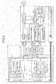
- FIG. 2 is a schematic block diagram of the configuration of the endoscopic system according to the first embodiment of the present invention.
- An endoscopic system 1 illustrated in FIG. 1 and FIG. 2 includes: an endoscope 2 whose tip is configured to be inserted into a body cavity of a subject to capture an in-vivo image of the subject; a processing device 3 that processes the in-vivo image taken with the endoscope 2 in a predetermined image process, and generally controls the operations of the whole endoscopic system 1; a light source device 4 that generates an illumination light to be emitted from the tip of the endoscope 2; and a display device 5 that displays the in-vivo image processed with the processing device 3.
- the endoscope 2 includes: an insertion unit 21 that has flexibility and elongated shape; an operating unit 22 that is connected to the proximal end of the insertion unit 21 so as to receive the input of various operation signals; and a universal cord 23 that extends in a direction opposite to the direction in which the insertion unit 21 extends from the operating unit 22, includes connectors 23a and 23b connected to the processing device 3 and the light source device 4, respectively, and incorporates various cables therein.
- the insertion unit 21 includes a tip portion 24 that incorporates an image sensor in which pixels, which generate signals by receiving light and performing photoelectric conversion on the received light, are two-dimensionally arranged; a curved portion 25 that is formed by a plurality of curved bridges and can curve freely; and a long flexible pipe portion 26 that is connected to the proximal end of the curved portion 25.
- the tip portion 24 includes a light guide 241, an illumination lens 242, two optical systems (optical systems 243A and 243B), a first image sensor 244A, and a second image sensor 244B.
- the light guide 241 is made, for example, of glass fiber and is a light guiding path for light emitted from the light source device 4.
- the illumination lens 242 is a lens that is provided on a tip of the light guide 241 and emits the illumination light.
- the optical systems 243A and 243B are configured to collect light. Each of the optical systems 243A and 243B includes one or plurality of lenses. The optical systems 243A and 243B can have an optical zoom function to vary the angle of view or a focus function to vary the focal point.
- Each of the first image sensor 244A and the second image sensor 244B includes: a sensor unit 244a that performs photoelectric conversion on the light collected by each of the optical systems 243A and 243B and generates an electric signal (hereinafter, referred to as an imaging signal); an analog front end unit 244b (hereinafter, referred to as an "AFE unit 244b") that removes noise from the imaging signal output from the sensor unit 244a and performs A/D conversion on the imaging signal; a P/S converter 244c that performs parallel-serial conversion on the imaging signal (a digital signal) output from the AFE unit 244b and transmits the converted imaging signal to the outside (the processing device 3); a timing generator 244d that generates the driving timing of the sensor unit 244a, and the pulses for various signal processes in the AFE unit 244b and P/S converter 244c; and an imaging controller 244e that controls the operation of the first image sensor 244A or the second image sensor 244B.
- an imaging signal here
- the sensor unit 244a includes a light receiving unit 244f and a reading unit 244g.
- a plurality of pixels each having a photodiode and a capacitor is arranged in a matrix form.
- the photodiode accumulates electric charge depending on the amount of light.
- the capacitor converts the electric charge transferred from the photodiode into a voltage level.
- Each of the pixels performs photoelectric conversion on the light from the optical system 243 to generate an electric signal.
- the reading unit 244g sequentially reads the electric signals generated by the pixels that are arbitrarily set as reading targets among the plurality of pixels in the light receiving unit 244f, and outputs the electric signals as imaging signals.
- a color filter is provided on a light-receiving surface of the light receiving unit 244f.
- the reading unit 244g sequentially reads, for each horizontal line, the electric signals generated by the plurality of pixels arranged in a matrix form.
- the AFE unit 244b includes: a noise reduction circuit that reduces the noise contents included in the analog imaging signals, for example, using a Correlated Double Sampling method; an Automatic Gain Control (AGC) circuit that maintains the output at a constant level by adjusting the amplification factor (gain) of the imaging signal (the electric signal); and an A/D conversion circuit that performs A/D conversion on the imaging signal output through the AGC circuit.
- AGC Automatic Gain Control
- the imaging controller 244e controls each of the operations of the first image sensor 244A or the second image sensor 244B in accordance with the control signal on the received setting data or the synchronization control.
- the imaging controller 244e for example, outputs the reading signal to the reading unit 244g and controls the output of the electric signal output from each pixel by the pixel.
- the imaging controller 244e includes, for example, a Central Processing Unit (CPU) or a register that stores various programs.
- the operating unit 22 is provided with: a curving knob 221 that curves the curved portion 25 up and down, and right and left; a treatment tool insertion unit 222 for inserting a treatment tool such as biopsy forceps, an electrical scalpel, or an inspection probe into the body cavity of the subject; and a plurality of switches 223 that are operation input units configured to input the instruction signals for the operations of peripheral devices such as an air feeding unit, a water feeding unit, and an image display control in addition to the processing device 3 and the light source device 4.
- the treatment tool inserted from the treatment tool insertion unit 222 extends outside from an opening portion (not illustrated) through a treatment tool channel (not illustrated) of the tip portion 24.
- the operating unit 22 further includes a first communication controller 224, a second communication controller 225, a first clock generator 226, and a second clock generator 227.
- the first communication controller 224 controls the driving timing at which the first image sensor 244A is driven in accordance with the setting data received from the processing device 3 or the control signal on synchronization control.
- the second communication controller 225 controls the driving timing at which the second image sensor 244B is driven in accordance with the setting data received from the processing device 3 or the control signal on synchronization control.
- the first clock generator 226 generates a clock signal (a first clock signal) to drive the first communication controller 224.
- the second clock generator 227 generates a clock signal (a second clock signal) to drive the second communication controller 225.
- the first clock generator 226 can be embedded in the first communication controller 224 and the second clock generator 227 can be embedded in the second communication controller 225.
- a microcomputer having a clock generating circuit is used for the first communication controller or the second communication controller, for example.
- the universal cord 23 incorporates at least the light guide 241 and a cable assembly 245 having one or more signal lines.
- the cable assembly 245 includes a signal line to transmit and receive the setting data, and a signal line to transmit and receive an imaging signal.
- the processing device 3 includes a first S/P converter 301A, a second S/P converter 301B, an image processing unit 302, a luminance detecting unit 303, a light adjusting unit 304, a driving signal generator 305, an input unit 306, a storage unit 307, a control unit 308, and a reference clock generator 309 (a third clock generator).
- the first S/P converter 301A and the second S/P converter 301B preform serial-parallel conversion on the imaging signals (digital signals) received from the tip portion 24 (the first image sensor 244A and the second image sensor 244B), respectively, and output the converted imaging signals to the image processing unit 302.
- the image processing unit 302 generates image signals to be displayed with the display device 5 based on the imaging signals input from the first S/P converter 301A and the second S/P converter 301B.
- the image processing unit 302 generates image signals including an in-vivo image to be displayed by processing the imaging signals in an predetermined image process.
- the image process includes a synchronization process, an optical black subtraction process, a white balance adjusting process, a color matrix operation process, a gamma correction process, a color reproduction process, an edge enhancement process, a synthesizing process for synthesizing a plurality of image data items, and a format conversion process.
- the image processing unit 302 generates image signals including a three-dimensional image, or a two-dimensional image having a large number of pixels based on the imaging signals generated by the first image sensor 244A and the second image sensor 244B.
- the image processing unit 302 further outputs the imaging signals input from the first S/P converter 301A and the second S/P converter 301B to the control unit 308 or the luminance detecting unit 303.
- the luminance detecting unit 303 detects the luminance level corresponding to each pixel from the image signals of RGB components output from the image processing unit 302.
- the luminance detecting unit 303 records the detected luminance level in an internal memory, and outputs the detected luminance level to the control unit 308.
- the luminance detecting unit 303 calculates a gain adjusting value and the amount of light irradiation based on the detected luminance level.
- the luminance detecting unit 303 outputs the calculated gain adjusting value to the image processing unit 302 while outputting the calculated amount of light irradiation to the light adjusting unit 304.
- the light adjusting unit 304 sets the amount of light generated by the light source device 4 and the light emitting timing in accordance with the amount of light irradiation calculated by the luminance detecting unit 303 under the control by the control unit 308. Then, the light adjusting unit 304 transmits the control signals including the set conditions to the light source device 4.
- the driving signal generator 305 generates a drive synchronization signal for driving the first image sensor 244A and the second image sensor 244B, and transmits the drive synchronization signal to the first communication controller 224 and the second communication controller 225.
- the driving signal generator 305 includes a reference synchronization signal generator 305a, and an imaging synchronization signal generator 305b.
- the reference synchronization signal generator 305a generates synchronization signals based on the clock signal generated by the reference clock generator 309.
- the synchronization signals generated by the reference synchronization signal generator 305a include reference synchronization signals that are references for the operation of each unit in the processing device 3 and the operations of the endoscope 2 and the light source device 4.
- the imaging synchronization signal generator 305b generates an imaging synchronization signal to drive the first image sensor 244A and the second image sensor 244B based on the clock signal generated by the reference clock generator 309, and outputs the imaging synchronization signal to the first communication controller 224 and the second communication controller 225. Specifically, the imaging synchronization signal generator 305b outputs an imaging synchronization signal.
- the imaging synchronization signal is a trigger for determining the imaging timing for the first image sensor 244A and the second image sensor 244B to start an imaging operation in response to the processing time of the first communication controller 224 and the second communication controller 225.
- the imaging timing is the starting timing at which an imaging operation starts.
- the imaging operation is for reading and obtaining the electric signals of a frame in an image.
- the input unit 306 receives the input of the various signals such as an operation instruction signal that instructs the operation of the endoscopic system 1.
- the storage unit 307 is implemented with a semiconductor memory such a flash memory or a Dynamic Random Access Memory (DRAM).
- the storage unit 307 stores various programs for operating the endoscopic system 1, and the data including various parameters necessary for the operation of the endoscopic system 1.
- the control unit 308 includes a CPU.
- the control unit 308 controls the driving of each of the elements including the tip portion 24 and the light source device 4, and controls the input and output of information to and from each of the elements.
- the control unit 308 transmits the setting data for controlling the imaging process to the imaging controller 244e through a predetermined signal line in the cable assembly 245.
- the setting data includes the imaging rate (frame rate) of the image sensor 244, settings for an electronic shutter or gain, the instruction information for instructing the reading rate at which the pixel information is read from an arbitrary pixel in the sensor unit 244a, and the transmitting control information of the pixel information read by the AFE unit 244b.
- the reference clock generator 309 generates a clock signal (a third clock) that is the reference for the operation of each element in the endoscopic system 1, and provides the generated clock signal to each element in the endoscopic system 1.
- a clock signal that the reference clock generator 309 generates is precise in comparison with the clock signals that the first clock generator 226 and the second clock generator 227 generate.
- the oscillator of the reference clock generator 309 create a precise frequency in comparison with the frequencies created with the oscillators of the first clock generator 226 and the second clock generator 227.
- the configuration of the light source device 4 will be described next.
- the light source device 4 includes a white light source 41, a light source controller 42, and a Light Emitting Diode (LED) driver 43.
- LED Light Emitting Diode
- the white light source 41 includes a white LED and generates a white illumination light under the control by the light source controller 42.
- the light source controller 42 controls the amount of current to be supplied to the white light source 41 in accordance with the control signal transmitted from the light adjusting unit 304.
- the LED driver 43 makes the white light source 41 generate the illumination light by supplying the current to the white light source 41 under the control by the light source controller 42.
- the light generated by the white light source 41 is emitted from the front end of the tip portion 24 through the light guide 241 to the outside.
- a special light source to generate an excitation light that excites a fluorescent material introduced in the subject can be provided in the light source device 4.
- the special light source generates, for example, an infrared light.
- the special light source can generate, as special light, light of any one of color components red, green, and blue at a wavelength band that is different from the wavelength band of the white luminance light and narrowed with a narrow band pass filter.
- the special light can be, for example, a Narrow Band Imaging (NBI) illumination light of two types of blue light and green light at narrowed bandwidths so that the special light can easily be absorbed in hemoglobin in the blood.
- NBI Narrow Band Imaging
- the display device 5 has a function to receive the in-vivo image generated by the processing device 3 through an image cable and displays the image.
- the display device 5 includes a display such as a liquid crystal display, or an organic Electro Luminescence (EL) display.
- first image sensor 244A, the second image sensor 244B, the first communication controller 224, the second communication controller 225, the first clock generator 226, the second clock generator 227, the reference synchronization signal generator 305a, and the imaging synchronization signal generator 305b are used to constitute the imaging device (the endoscopic device) in the first embodiment.
- FIG. 3 is a timing chart of the control timing of the endoscopic system according to the first embodiment.
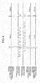
- FIG. 4 is a timing chart of the control timing of the endoscopic system according to the first embodiment, illustrating a part of FIG. 3 in more detail.
- the first image sensor 244A and the second image sensor 244B alternately repeat the exposure on the light receiving unit 244f and the reading of an electric signal of a horizontal line with the reading unit 244g so as to obtain the imaging signals including the in-vivo image of the subject.
- the first image sensor 244A and the second image sensor 244B alternately read each of first to n-th horizontal lines (of a frame) at different points in time.
- a period required for the exposure process and reading process with the first image sensor 244A and the second image sensor 244B is referred to as a field.
- the reading process is for reading the electric signal generated by the exposure process. In other words, for example, an exposure process and a reading process for obtaining the electric signals (the imaging signals) of a frame included in an image are performed in a field.
- the field is switched from a field 1 to a field 2 at an internal synchronization timing (a reference synchronization signal) in the processing device 3.
- the reference timing based on the synchronization timing (the reference synchronization signal) sometimes differs from a desired timing at which the image sensor starts the reading process.
- the control unit 308 transmits the synchronization signal generated in the imaging synchronization signal generator 305b to the first communication controller 224 and the second communication controller 225.
- the first communication controller 224 and the second communication controller 225 start a synchronization control communication, using the reference synchronization signal from the driving signal generator 305 as a trigger for the communication.
- the synchronization control communication is for synchronization control that determines an imaging timing (vertical synchronization timing) and includes the settings (register settings) for the operation conditions of the first image sensor 244A and the second image sensor 244B.
- the first communication controller 224 starts the synchronization control communication after counting a predetermined period of time from the synchronization timing based on the clock signal generated in the first clock generator 226.
- the second communication controller 225 starts the synchronization control communication after counting a predetermined period of time from the synchronization timing based on the clock signal generated in the second clock generator 227.
- control unit 308 transmits the setting data, for example, in a publicly known communication standard such as I 2 C or SPI so that various settings for each image sensor (for example, the settings for controlling the luminance of the electronic shutter, the designation of the device, and the designation of the address) are configured.
- a publicly known communication standard such as I 2 C or SPI
- the imaging synchronization signal generated by the imaging synchronization signal generator 305b is transmitted to the endoscope 2 (the first communication controller 224 and the second communication controller 225).
- the imaging synchronization signal transmitted from the imaging synchronization signal generator 305b is used as a trigger for the control to complete the synchronization control communication, and a signal for determining the last communication in the synchronization control communication by the first communication controller 224 and the second communication controller 225.
- the imaging synchronization signal generator 305b counts the elapsed period between the synchronization timing of the processing device 3 and the timing of the last communication in the synchronization control communication by the first communication controller 224, and the elapsed period between the synchronization timing of the processing device 3 and the timing of the last communication in the synchronization control communication by the second communication controller 225. Then, the imaging synchronization signal generator 305b outputs an imaging synchronization signal at a timing determined in accordance with the amount of the time lag between the two elapsed periods (the number of clocks) and the timing of completing the synchronization control communications.
- each of the first communication controller 224 and the second communication controller 225 performs the last communication, using the reception of the imaging synchronization signal as a trigger.
- the imaging synchronization signal generator 305b outputs the imaging synchronization signal after counting a predetermined period of time from the reference timing based on the synchronization timing (the reference synchronization signal).
- the reference timing can be an arbitrary timing, for example, the timing at which the reference synchronization signal is output, or the timing at which the first communication controller 224 or the second communication controller 225 starts the synchronization control communication.
- the imaging synchronization signal generator 305b can determine the number of clocks (the elapsed period) by counting the period elapsed in the synchronization control communication previously performed, or by counting the period elapsed in the communication performed when the endoscopic system 1 starts.
- the first communication controller 224 performs the synchronization control communication based on the synchronization timing of the processing device 3, and suspends the communication until just before the last communication in the synchronization control communication.
- the second communication controller 225 performs the synchronization control communication based on the timing counted with the clocks generated by the second clock generator 227, and suspends the communication until just before the last communication in the synchronization control communication.
- the frequency of the clock generated in first clock generator 226 slightly differs from the frequency of the clock generated in the second clock generator 227. In FIG. 4 , there is a time lag in counting between the second communication controller 255 and the first communication controller 224 even if the first communication controller 224 and the second communication controller 225 start a communication at the same time.
- the second communication controller 225 performs the communication at a timing later than a timing in the first communication controller 224.
- the first communication controller 224 and the second communication controller 225 perform the last communication in the synchronization control communication, using the imaging synchronization signal from the imaging synchronization signal generator 305b as a trigger.
- the first communication controller 224 when the signal is latched with the falling edge of the last clock in the communication, the first communication controller 224 generates a falling clock with the imaging synchronization signal from the imaging synchronization signal generator 305b as illustrated in FIG. 4 .
- the second communication controller 225 generates a falling clock, using the imaging synchronization signal as a trigger. Generating the falling clocks determines the vertical synchronization timing (imaging timing) of the first image sensor 244A and the second image sensor 244B, and switches the field. When the field is switched, the reading unit 244g starts a reading process.
- the first communication controller 224 and the second communication controller 225 performed the last communication in the synchronization control communication, using the imaging synchronization signal counted with the reference clock as a trigger as described above.
- the points in time of completing synchronization control communication of the first communication controller 224 and the second communication controller 225 are approximately identical. This can control the synchronization between the first communication controller 224 and the second communication controller 225 with a high degree of accuracy even if there is a time lag between the periods counted with the first communication controller 224 and the second communication controller 225.
- the timing at which the imaging synchronization signal is input is shorter than the period between the start and completion of the synchronization control communication by the first communication controller 224 and the second communication controller 225.
- the imaging synchronization signal is preferably output after the communications start.
- the first communication controller 224 and the second communication controller 225 perform the last communication in the synchronization control communication, using the imaging synchronization signal as a trigger. This determines the vertical synchronization timing (the imaging timing) of each of the first image sensor 244A and the second image sensor 244B. This can synchronize a plurality of image sensors with a high degree of accuracy.
- the first communication controller 224 counts a predetermined period of time based on the clocks generated by the first clock generator 226 so that the first image sensor 244A starts the synchronization control communication. Note that, however, the first communication controller 224 can start the communication, for example, at the communication starting timing (not illustrated) transmitted from the control unit 308. This can control also the communication starting timing with a high degree of accuracy although increasing the number of control lines.
- the first communication controller 224 and the second communication controller 225 perform a synchronization control communication in every field.
- the first communication controller 224 and the second communication controller 225 can perform the communication every several fields or in predetermined fields.
- the field is switched at the falling of the last pulse.
- the field can be switched after several clocks are counted from the falling of the last pulse.
- the imaging synchronization signal is the trigger for the last communication.
- a falling clock can be generated just after the imaging synchronization signal is received, or the falling clock can be generated after several clocks are counted.
- the timing of the last communication can be controlled in any way as long as the reception of the imaging synchronization signal is used as the trigger.
- the processing device 3 is provided with the imaging synchronization signal generator 305b.
- a counter can be provided in the endoscope 2, for example, in the connector 23a.
- a clock generator corresponding to the reference clock generator 309 is preferably provided in the endoscope 2.
- FIG. 5 is a schematic block diagram of the configuration of an endoscopic system according to the second embodiment.
- the same elements as those in the above-described embodiment will be denoted by the same reference signs.
- a horizontal synchronization signal is extracted from the obtained imaging signals.
- the vertical synchronization timing is determined in accordance with the horizontal synchronization timing of a first image sensor 244A and a second image sensor 244B. Then, the field is switched.
- An endoscopic system 1a includes an endoscope 2, a light source device 4, a display device 5, and a processing device 3a.
- the processing device 3a includes a first synchronization signal extracting unit 310A and a second synchronization signal extracting unit 310B in addition to the elements of the processing device 3.
- the vertical synchronization timing of the first image sensor 244A and the second image sensor 244B is controlled by the horizontal synchronization timing in the second embodiment.
- the register settings for each image sensor are configured. After the register settings is completed, a synchronization signal is generated in each image sensor based on the first horizontal synchronization timing. Each image sensor is driven in accordance with the generated synchronization signal.
- the first image sensor 244A, the second image sensor 244B, a first communication controller 224, a second communication controller 225, a first clock generator 226, a second clock generator 227, a reference synchronization signal generator 305a, an imaging synchronization signal generator 305b, and the synchronization signal extracting unit (the first synchronization signal extracting unit 310A and the second synchronization signal extracting unit 310B) are used to constitute an imaging device in the second embodiment.
- the first synchronization signal extracting unit 310A and the second synchronization signal extracting unit 310B obtain the imaging signals generated in the endoscope 2 through a first S/P converter 301A and a second S/P converter 301B, respectively.
- the first synchronization signal extracting unit 310A and the second synchronization signal extracting unit 310B separate the imaging signals into the image signals and the synchronization signals, and extract the horizontal synchronization signal from the separated signals.
- the imaging synchronization signal generator 305b generates a horizontal synchronization signal in accordance with an interval between adjacent pulses in the horizontal synchronization signal extracted with each of the first synchronization signal extracting unit 310A and the second synchronization signal extracting unit 310B. Specifically, the imaging synchronization signal generator 305b generates an imaging synchronization signal.
- the imaging synchronization signal is output such that the timings of completing the communications of the first communication controller 224 and the second communication controller 225 are located at the same interval between the pulses.
- the imaging synchronization signal according to the second embodiment is the trigger for the control of the completion of the synchronization control communication. Specifically, when the imaging synchronization signal is received, the reception is used as the trigger for the last communication.
- FIG. 6 is a timing chart of the control timing for controlling the endoscopic system according to the second embodiment.
- the first communication controller 224 and the second communication controller 225 start a synchronization control communication based on the clock that each of the first communication controller 224 and the second communication controller 225 counts, or start a synchronization control communication based on the synchronization timing of the processing device 3, similarly to the first embodiment.
- the first communication controller 224 and the second communication controller 225 use the imaging synchronization signal as a trigger, and perform the synchronization control communication, for example, while suspending the synchronization control communication for a period of several clocks. Specifically, the first communication controller 224 and the second communication controller 225 delay the timing of completing communication by suspending the communication for a period of a set number of clocks until the first communication controller 224 and the second communication controller 225 perform the last communication in response to an imaging synchronization signal from the imaging synchronization signal generator 305b, as illustrated in FIG. 6 .
- the first communication controller 224 and the second communication controller 225 that suspend the communication just before the last communication in a synchronization control communication can perform the last communication and complete the communication, using the imaging synchronization signal as a trigger.
- the horizontal synchronization timings for determining the vertical synchronization timings between the first image sensor 244A and the second image sensor 244B are matched.
- the vertical synchronization timings of the first image sensor 244A and the second image sensor 244B are also matched.
- the field can be switched with the corresponding vertical synchronization timing. After the field is switched, the reading unit 244g starts a reading process.
- the first communication controller 224 and the second communication controller 225 adjust the timing of completing the synchronization control, using the imaging synchronization signal as a trigger. It is therefore possible to control the synchronization between the first communication controller 224 and the second communication controller 225 with a high degree of accuracy even if there is a difference in counts between the first communication controller 224 and the second communication controller 225.
- the first communication controller 224 and the second communication controller 225 adjust the completion of the synchronization control by counting a predetermined number of clocks, using the imaging synchronization signal as a trigger. This leads to the matching between the horizontal synchronization timings and to the matching between the vertical synchronization timings. It is therefore possible to synchronize a plurality of image sensors with a high degree of accuracy.
- the processing device 3 includes the imaging synchronization signal generator 305b, the first synchronization signal extracting unit 310A and the second synchronization signal extracting unit 310B.
- the counter and the synchronization signal extracting units can be provided in the endoscope 2, for example, in the connector 23a.
- a clock generator corresponding to the reference clock generator 309 is preferably provided in the endoscope 2.
- the first synchronization signal extracting unit 310A and the second synchronization signal extracting unit 310B obtain the imaging signals from the AFE unit 244b or the P/S converter 244c, and extract the horizontal synchronization signals.
- the completion of the synchronization signals may occur at different points in time as long as the timings of completing the synchronization control of the first communication controller 224 and the second communication controller 225 are located in the same interval between the pulses in the horizontal synchronization signal.
- the vertical synchronization timing is determined with the timing at which the control communication is completed (or the horizontal synchronization timing just after the completion). Any data item in the control communication can be set as the timing data for determining the vertical synchronization timing instead of the timing at which the control communication is completed. In such a case, the imaging synchronization signal is transmitted so that the setting data is set at the timing (for example, at an interval between the horizontal synchronization pulses).
- a rotation filter can be arranged on the light path on which the white light source 41 emits a white light in the first and second embodiments.
- the rotation filter includes a plurality of filters to make only light at predetermined wavelength bands in the white light penetrate by rotating the filters.
- the provided rotation filter makes the light having wavelength bands of the red light (R), green light (G), and blue light (B) sequentially penetrate so that the light are emitted. This can sequentially emit the red light (R illumination), green light (G illumination), and blue light (B illumination) at narrowed bandwidths in the white light that the white light source 41 emits (W illumination) to the endoscope 2 (in a frame sequential method). In the emission, performing the imaging control as described above can reduce the color deviation between the images.
- the reference synchronization signal (the synchronization timing) for causing the first image sensor 244A and the second image sensor 244B to start the imaging operation is generated based on the clock signal generated by the reference clock generator 309.
- the reference synchronization signal can be generated based on the clock signal generated by the first clock generator 226, the second clock generator 227, or an external clock generator.
- the synchronization between the two image sensors is controlled in the first and second embodiments.
- the imaging process can also be controlled when three or more image sensors are provided.
- the imaging device and the endoscopic device according to the present invention are useful for synchronizing a plurality of image sensors with a high degree of accuracy.
Landscapes
- Engineering & Computer Science (AREA)
- Life Sciences & Earth Sciences (AREA)
- Health & Medical Sciences (AREA)
- Physics & Mathematics (AREA)
- Surgery (AREA)
- Signal Processing (AREA)
- Optics & Photonics (AREA)
- Multimedia (AREA)
- Medical Informatics (AREA)
- Animal Behavior & Ethology (AREA)
- Pathology (AREA)
- Radiology & Medical Imaging (AREA)
- Veterinary Medicine (AREA)
- Biomedical Technology (AREA)
- Heart & Thoracic Surgery (AREA)
- Biophysics (AREA)
- Molecular Biology (AREA)
- Nuclear Medicine, Radiotherapy & Molecular Imaging (AREA)
- General Health & Medical Sciences (AREA)
- Public Health (AREA)
- Astronomy & Astrophysics (AREA)
- General Physics & Mathematics (AREA)
- Human Computer Interaction (AREA)
- Endoscopes (AREA)
- Instruments For Viewing The Inside Of Hollow Bodies (AREA)
Abstract
Description
- The present invention relates to an imaging device including a plurality of image sensors, and to an endoscopic device.
- Endoscopic systems have been used to observe an organ of a subject such as a patient in the medical field. The endoscopic system includes: an endoscope that includes an insertion unit provided with an image sensor on its tip, having flexibility and an elongated shape, and configured to be inserted into a body cavity of the subject; and a processing device that is connected to the proximal end of the insertion unit through a cable, processes an in-vivo image in accordance with the imaging signals generated by the image sensor, and displays the in-vivo image, for example, on a display unit.
- A technique in which an endoscopic system is provided with a plurality of image sensors including CMOS image sensors on a tip of an endoscope so as to generate a three-dimensional image or generate a clear two-dimensional image based on the images taken by the image sensors has been known (for example, see Patent Literature 1). For example, the image sensors are connected to a processing device through dedicated lines (parallel bus) so as to transmit signals in
Patent Literature 1. A timing generator generates a signal for driving the image sensors using a common clock, and this synchronizes the image sensors inPatent Literature 1. - Patent Literature 1: Japanese Patent Application Laid-open No.
2006-181021 - It is desirable to reduce the diameter of the insertion unit of the endoscope in consideration of easy insertion into the patient. To reduce the diameter of the insertion unit with a plurality of image sensors of the endoscope, a technique in which a serial bus is used to perform the register settings and perform the control of synchronization of the image sensors instead of dedicated lines being used to transmit the synchronization signal to the image sensors has been known.
- According to the technique in which the serial bus is used to perform the register settings, a communication controller that can communicate with the processing device and is provided in each of the image sensors configures the register settings for each of the image sensors. A synchronization signal is generated in each of the image sensors at the timing of completing the register settings. Each of the image sensors is driven in accordance with the synchronization signal. When the communication controllers, which control the serial bus, count timing of control based on individual clocks to control the image sensors, for example, the deviations among the clocks can cause the time lags among the periods counted by the communication controllers. This sometimes causes the loss of synchronization (gap in driving timing) among the image sensors.
- The present invention has been made in view of the foregoing, an object of the invention is to provide an imaging device and an endoscopic device that can synchronize a plurality of image sensors with a high degree of accuracy.
- In order to solve the above described problems and achieve the object, an imaging device according to the invention includes: first and second image sensors configured to receive light and to perform photoelectric conversion on the received light to generate electric signals; a first communication controller configured to be connected to the first image sensor to perform communication with the first image sensor and to control the communication to perform operating control on the first image sensor; a first clock generator configured to generate a first clock signal that is a reference for operation of the first communication controller; a second communication controller configured to be connected to the second image sensor to perform communication with the second image sensor and to control the communication to perform operating control on the second image sensor; a second clock generator configured to generate a second clock signal that is a reference for operation of the second communication controller; a reference synchronization signal generator configured to generate a reference synchronization signal; and an imaging synchronization signal generator configured to generate an imaging synchronization signal that is a trigger for determining timings of imaging by the first and second image sensors, and to output the imaging synchronization signal to the first and second communication controllers at a timing when a predetermined period of time has elapsed from a reference timing based on the reference synchronization signal. When the first and second communication controllers perform synchronization control communications for synchronizing the timings of imaging by the first and second image sensors, the first and second communication controllers are configured to determine the timings of imaging by the first and second image sensors using the imaging synchronization signal output from the imaging synchronization signal generator as a trigger.
- The imaging device according to the above-described invention further includes a third clock generator configured to generate a third clock signal with higher precision of frequency than the first and second clock signals. The reference synchronization signal generator is configured to generate the reference synchronization signal based on the third clock signal.
- The imaging device according to the above-described invention further includes a synchronization signal extracting unit configured to extract a horizontal synchronization signal from the electric signals generated by the first and second image sensors. The imaging synchronization signal generator is configured to generate the imaging synchronization signal such that timings of completing the synchronization control communications between the first and second image sensors and the first and second communication controllers are located in a same interval between horizontal synchronization pulses and do not overlap with the horizontal synchronization pulses.
- In the imaging device according to the above-described invention, a timing of inputting the imaging synchronization signal is shorter than a period of time between when the first and second communication controllers start the synchronization control communications and when the first and second communication controllers complete the synchronization control communications.
- An endoscopic device according to the invention includes: an insertion unit that has an elongated shape and is configured to be inserted into a living body; first and second image sensors configured to receive light and to perform photoelectric conversion on the received light to generate electric signals; a first communication controller configured to be connected to the first image sensor to perform communication with the first image sensor and to control the communication to perform operating control on the first image sensor; a first clock generator configured to generate a first clock signal that is a reference for operation of the first communication controller; a second communication controller configured to be connected to the second image sensor to perform communication with the second image sensor and to control the communication to perform operating control on the second image sensor; a second clock generator configured to generate a second clock signal that is a reference for operation of the second communication controller; a reference synchronization signal generator configured to generate a reference synchronization signal; and an imaging synchronization signal generator configured to generate an imaging synchronization signal that is a trigger for determining timings of imaging by the first and second image sensors, and to output the imaging synchronization signal to the first and second communication controllers at a timing when a predetermined period of time has elapsed from a reference timing based on the reference synchronization signal. When the first and second communication controllers perform synchronization control communications for synchronizing the timings of imaging by the first and second image sensors, the first and second communication controllers are configured to determine the timings of imaging by the first and second image sensors using the imaging synchronization signal output from the imaging synchronization signal generator as a trigger.
- According to the invention, it is possible to synchronize a plurality of image sensors with a high degree of accuracy.
-
-
FIG. 1 is a schematic diagram of the configuration of an endoscopic system according to a first embodiment of the present invention. -
FIG. 2 is a schematic block diagram of the configuration of the endoscopic system according to the first embodiment of the present invention. -
FIG. 3 is a timing chart of the control timing of the endoscopic system according to the first embodiment of the present invention. -
FIG. 4 is a timing chart of the control timing of the endoscopic system according to the first embodiment of the present invention, illustrating a part ofFIG. 3 in more detail. -
FIG. 5 is a schematic block diagram of the configuration of an endoscopic system according to a second embodiment of the present invention. -
FIG. 6 is a timing chart of the control timing of the endoscopic system according to the second embodiment of the present invention. - Modes for carrying out the present invention (hereinafter, referred to as "embodiment(s)") will be described below. A medical endoscopic system that takes an image of the inside of the body cavity of a subject such as a patient and displays the image will be described in the embodiments as an exemplary system including the imaging device and endoscopic device according to the present invention. The present invention is not limited to the embodiments. The same reference signs are used to designate the same elements throughout the drawings.
-
FIG. 1 is a schematic diagram of the configuration of an endoscopic system according to a first embodiment of the present invention.FIG. 2 is a schematic block diagram of the configuration of the endoscopic system according to the first embodiment of the present invention. - An
endoscopic system 1 illustrated inFIG. 1 andFIG. 2 includes: anendoscope 2 whose tip is configured to be inserted into a body cavity of a subject to capture an in-vivo image of the subject; aprocessing device 3 that processes the in-vivo image taken with theendoscope 2 in a predetermined image process, and generally controls the operations of the wholeendoscopic system 1; alight source device 4 that generates an illumination light to be emitted from the tip of theendoscope 2; and adisplay device 5 that displays the in-vivo image processed with theprocessing device 3. - The
endoscope 2 includes: aninsertion unit 21 that has flexibility and elongated shape; anoperating unit 22 that is connected to the proximal end of theinsertion unit 21 so as to receive the input of various operation signals; and auniversal cord 23 that extends in a direction opposite to the direction in which theinsertion unit 21 extends from theoperating unit 22, includesconnectors processing device 3 and thelight source device 4, respectively, and incorporates various cables therein. - The
insertion unit 21 includes atip portion 24 that incorporates an image sensor in which pixels, which generate signals by receiving light and performing photoelectric conversion on the received light, are two-dimensionally arranged; acurved portion 25 that is formed by a plurality of curved bridges and can curve freely; and a longflexible pipe portion 26 that is connected to the proximal end of thecurved portion 25. - The
tip portion 24 includes alight guide 241, anillumination lens 242, two optical systems (optical systems first image sensor 244A, and asecond image sensor 244B. - The
light guide 241 is made, for example, of glass fiber and is a light guiding path for light emitted from thelight source device 4. Theillumination lens 242 is a lens that is provided on a tip of thelight guide 241 and emits the illumination light. - The
optical systems optical systems optical systems - Each of the
first image sensor 244A and thesecond image sensor 244B includes: asensor unit 244a that performs photoelectric conversion on the light collected by each of theoptical systems front end unit 244b (hereinafter, referred to as an "AFE unit 244b") that removes noise from the imaging signal output from thesensor unit 244a and performs A/D conversion on the imaging signal; a P/S converter 244c that performs parallel-serial conversion on the imaging signal (a digital signal) output from theAFE unit 244b and transmits the converted imaging signal to the outside (the processing device 3); atiming generator 244d that generates the driving timing of thesensor unit 244a, and the pulses for various signal processes in theAFE unit 244b and P/S converter 244c; and animaging controller 244e that controls the operation of thefirst image sensor 244A or thesecond image sensor 244B. Each of thefirst image sensor 244A and thesecond image sensor 244B is implemented with a Complementary Metal Oxide Semiconductor (CMOS) image sensor. - The
sensor unit 244a includes alight receiving unit 244f and areading unit 244g. In thelight receiving unit 244f, a plurality of pixels each having a photodiode and a capacitor is arranged in a matrix form. The photodiode accumulates electric charge depending on the amount of light. The capacitor converts the electric charge transferred from the photodiode into a voltage level. Each of the pixels performs photoelectric conversion on the light from the optical system 243 to generate an electric signal. Thereading unit 244g sequentially reads the electric signals generated by the pixels that are arbitrarily set as reading targets among the plurality of pixels in thelight receiving unit 244f, and outputs the electric signals as imaging signals. A color filter is provided on a light-receiving surface of thelight receiving unit 244f. Thereading unit 244g sequentially reads, for each horizontal line, the electric signals generated by the plurality of pixels arranged in a matrix form. - The
AFE unit 244b includes: a noise reduction circuit that reduces the noise contents included in the analog imaging signals, for example, using a Correlated Double Sampling method; an Automatic Gain Control (AGC) circuit that maintains the output at a constant level by adjusting the amplification factor (gain) of the imaging signal (the electric signal); and an A/D conversion circuit that performs A/D conversion on the imaging signal output through the AGC circuit. - The
imaging controller 244e controls each of the operations of thefirst image sensor 244A or thesecond image sensor 244B in accordance with the control signal on the received setting data or the synchronization control. Theimaging controller 244e, for example, outputs the reading signal to thereading unit 244g and controls the output of the electric signal output from each pixel by the pixel. Theimaging controller 244e includes, for example, a Central Processing Unit (CPU) or a register that stores various programs. - The operating
unit 22 is provided with: a curvingknob 221 that curves thecurved portion 25 up and down, and right and left; a treatmenttool insertion unit 222 for inserting a treatment tool such as biopsy forceps, an electrical scalpel, or an inspection probe into the body cavity of the subject; and a plurality ofswitches 223 that are operation input units configured to input the instruction signals for the operations of peripheral devices such as an air feeding unit, a water feeding unit, and an image display control in addition to theprocessing device 3 and thelight source device 4. The treatment tool inserted from the treatmenttool insertion unit 222 extends outside from an opening portion (not illustrated) through a treatment tool channel (not illustrated) of thetip portion 24. - The operating
unit 22 further includes afirst communication controller 224, a second communication controller 225, afirst clock generator 226, and asecond clock generator 227. Thefirst communication controller 224 controls the driving timing at which thefirst image sensor 244A is driven in accordance with the setting data received from theprocessing device 3 or the control signal on synchronization control. The second communication controller 225 controls the driving timing at which thesecond image sensor 244B is driven in accordance with the setting data received from theprocessing device 3 or the control signal on synchronization control. Thefirst clock generator 226 generates a clock signal (a first clock signal) to drive thefirst communication controller 224. Thesecond clock generator 227 generates a clock signal (a second clock signal) to drive the second communication controller 225. Note that thefirst clock generator 226 can be embedded in thefirst communication controller 224 and thesecond clock generator 227 can be embedded in the second communication controller 225. A microcomputer having a clock generating circuit is used for the first communication controller or the second communication controller, for example. - The
universal cord 23 incorporates at least thelight guide 241 and acable assembly 245 having one or more signal lines. Thecable assembly 245 includes a signal line to transmit and receive the setting data, and a signal line to transmit and receive an imaging signal. - The configuration of the
processing device 3 will be described next. Theprocessing device 3 includes a first S/P converter 301A, a second S/P converter 301B, animage processing unit 302, aluminance detecting unit 303, a light adjusting unit 304, a drivingsignal generator 305, aninput unit 306, a storage unit 307, a control unit 308, and a reference clock generator 309 (a third clock generator). - The first S/
P converter 301A and the second S/P converter 301B preform serial-parallel conversion on the imaging signals (digital signals) received from the tip portion 24 (thefirst image sensor 244A and thesecond image sensor 244B), respectively, and output the converted imaging signals to theimage processing unit 302. - The
image processing unit 302 generates image signals to be displayed with thedisplay device 5 based on the imaging signals input from the first S/P converter 301A and the second S/P converter 301B. Theimage processing unit 302 generates image signals including an in-vivo image to be displayed by processing the imaging signals in an predetermined image process. The image process includes a synchronization process, an optical black subtraction process, a white balance adjusting process, a color matrix operation process, a gamma correction process, a color reproduction process, an edge enhancement process, a synthesizing process for synthesizing a plurality of image data items, and a format conversion process. Theimage processing unit 302 generates image signals including a three-dimensional image, or a two-dimensional image having a large number of pixels based on the imaging signals generated by thefirst image sensor 244A and thesecond image sensor 244B. Theimage processing unit 302 further outputs the imaging signals input from the first S/P converter 301A and the second S/P converter 301B to the control unit 308 or theluminance detecting unit 303. - The
luminance detecting unit 303 detects the luminance level corresponding to each pixel from the image signals of RGB components output from theimage processing unit 302. Theluminance detecting unit 303 records the detected luminance level in an internal memory, and outputs the detected luminance level to the control unit 308. Theluminance detecting unit 303 calculates a gain adjusting value and the amount of light irradiation based on the detected luminance level. Theluminance detecting unit 303 outputs the calculated gain adjusting value to theimage processing unit 302 while outputting the calculated amount of light irradiation to the light adjusting unit 304. - The light adjusting unit 304 sets the amount of light generated by the
light source device 4 and the light emitting timing in accordance with the amount of light irradiation calculated by theluminance detecting unit 303 under the control by the control unit 308. Then, the light adjusting unit 304 transmits the control signals including the set conditions to thelight source device 4. - The driving
signal generator 305 generates a drive synchronization signal for driving thefirst image sensor 244A and thesecond image sensor 244B, and transmits the drive synchronization signal to thefirst communication controller 224 and the second communication controller 225. - The driving
signal generator 305 includes a referencesynchronization signal generator 305a, and an imagingsynchronization signal generator 305b. The referencesynchronization signal generator 305a generates synchronization signals based on the clock signal generated by thereference clock generator 309. The synchronization signals generated by the referencesynchronization signal generator 305a include reference synchronization signals that are references for the operation of each unit in theprocessing device 3 and the operations of theendoscope 2 and thelight source device 4. - The imaging
synchronization signal generator 305b generates an imaging synchronization signal to drive thefirst image sensor 244A and thesecond image sensor 244B based on the clock signal generated by thereference clock generator 309, and outputs the imaging synchronization signal to thefirst communication controller 224 and the second communication controller 225. Specifically, the imagingsynchronization signal generator 305b outputs an imaging synchronization signal. The imaging synchronization signal is a trigger for determining the imaging timing for thefirst image sensor 244A and thesecond image sensor 244B to start an imaging operation in response to the processing time of thefirst communication controller 224 and the second communication controller 225. The imaging timing is the starting timing at which an imaging operation starts. The imaging operation is for reading and obtaining the electric signals of a frame in an image. - The
input unit 306 receives the input of the various signals such as an operation instruction signal that instructs the operation of theendoscopic system 1. - The storage unit 307 is implemented with a semiconductor memory such a flash memory or a Dynamic Random Access Memory (DRAM). The storage unit 307 stores various programs for operating the
endoscopic system 1, and the data including various parameters necessary for the operation of theendoscopic system 1. - The control unit 308 includes a CPU. The control unit 308 controls the driving of each of the elements including the
tip portion 24 and thelight source device 4, and controls the input and output of information to and from each of the elements. The control unit 308 transmits the setting data for controlling the imaging process to theimaging controller 244e through a predetermined signal line in thecable assembly 245. The setting data includes the imaging rate (frame rate) of the image sensor 244, settings for an electronic shutter or gain, the instruction information for instructing the reading rate at which the pixel information is read from an arbitrary pixel in thesensor unit 244a, and the transmitting control information of the pixel information read by theAFE unit 244b. - The
reference clock generator 309 generates a clock signal (a third clock) that is the reference for the operation of each element in theendoscopic system 1, and provides the generated clock signal to each element in theendoscopic system 1. In the first embodiment, a clock signal that thereference clock generator 309 generates is precise in comparison with the clock signals that thefirst clock generator 226 and thesecond clock generator 227 generate. Specifically, the oscillator of thereference clock generator 309 create a precise frequency in comparison with the frequencies created with the oscillators of thefirst clock generator 226 and thesecond clock generator 227. - The configuration of the
light source device 4 will be described next. Thelight source device 4 includes a white light source 41, alight source controller 42, and a Light Emitting Diode (LED)driver 43. - The white light source 41 includes a white LED and generates a white illumination light under the control by the
light source controller 42. - The
light source controller 42 controls the amount of current to be supplied to the white light source 41 in accordance with the control signal transmitted from the light adjusting unit 304. - The
LED driver 43 makes the white light source 41 generate the illumination light by supplying the current to the white light source 41 under the control by thelight source controller 42. The light generated by the white light source 41 is emitted from the front end of thetip portion 24 through thelight guide 241 to the outside. - Note that a special light source to generate an excitation light that excites a fluorescent material introduced in the subject can be provided in the
light source device 4. The special light source generates, for example, an infrared light. The special light source can generate, as special light, light of any one of color components red, green, and blue at a wavelength band that is different from the wavelength band of the white luminance light and narrowed with a narrow band pass filter. The special light can be, for example, a Narrow Band Imaging (NBI) illumination light of two types of blue light and green light at narrowed bandwidths so that the special light can easily be absorbed in hemoglobin in the blood. - The
display device 5 has a function to receive the in-vivo image generated by theprocessing device 3 through an image cable and displays the image. Thedisplay device 5 includes a display such as a liquid crystal display, or an organic Electro Luminescence (EL) display. - Note that the
first image sensor 244A, thesecond image sensor 244B, thefirst communication controller 224, the second communication controller 225, thefirst clock generator 226, thesecond clock generator 227, the referencesynchronization signal generator 305a, and the imagingsynchronization signal generator 305b are used to constitute the imaging device (the endoscopic device) in the first embodiment. - The synchronization control of the imaging timing in the
endoscopic system 1 will be described next with reference toFIGS. 3 and4 .FIG. 3 is a timing chart of the control timing of the endoscopic system according to the first embodiment.FIG. 4 is a timing chart of the control timing of the endoscopic system according to the first embodiment, illustrating a part ofFIG. 3 in more detail. - The
first image sensor 244A and thesecond image sensor 244B alternately repeat the exposure on thelight receiving unit 244f and the reading of an electric signal of a horizontal line with thereading unit 244g so as to obtain the imaging signals including the in-vivo image of the subject. Thefirst image sensor 244A and thesecond image sensor 244B alternately read each of first to n-th horizontal lines (of a frame) at different points in time. In the first embodiment, a period required for the exposure process and reading process with thefirst image sensor 244A and thesecond image sensor 244B is referred to as a field. The reading process is for reading the electric signal generated by the exposure process. In other words, for example, an exposure process and a reading process for obtaining the electric signals (the imaging signals) of a frame included in an image are performed in a field. - The field is switched from a
field 1 to afield 2 at an internal synchronization timing (a reference synchronization signal) in theprocessing device 3. The reference timing based on the synchronization timing (the reference synchronization signal) sometimes differs from a desired timing at which the image sensor starts the reading process. In light of the foregoing, the control unit 308 transmits the synchronization signal generated in the imagingsynchronization signal generator 305b to thefirst communication controller 224 and the second communication controller 225. - The
first communication controller 224 and the second communication controller 225 start a synchronization control communication, using the reference synchronization signal from the drivingsignal generator 305 as a trigger for the communication. The synchronization control communication is for synchronization control that determines an imaging timing (vertical synchronization timing) and includes the settings (register settings) for the operation conditions of thefirst image sensor 244A and thesecond image sensor 244B. At that time, thefirst communication controller 224 starts the synchronization control communication after counting a predetermined period of time from the synchronization timing based on the clock signal generated in thefirst clock generator 226. Meanwhile, the second communication controller 225 starts the synchronization control communication after counting a predetermined period of time from the synchronization timing based on the clock signal generated in thesecond clock generator 227. In the register settings, the control unit 308 transmits the setting data, for example, in a publicly known communication standard such as I2C or SPI so that various settings for each image sensor (for example, the settings for controlling the luminance of the electronic shutter, the designation of the device, and the designation of the address) are configured. - After that, the imaging synchronization signal generated by the imaging
synchronization signal generator 305b is transmitted to the endoscope 2 (thefirst communication controller 224 and the second communication controller 225). The imaging synchronization signal transmitted from the imagingsynchronization signal generator 305b is used as a trigger for the control to complete the synchronization control communication, and a signal for determining the last communication in the synchronization control communication by thefirst communication controller 224 and the second communication controller 225. - Specifically, the imaging
synchronization signal generator 305b counts the elapsed period between the synchronization timing of theprocessing device 3 and the timing of the last communication in the synchronization control communication by thefirst communication controller 224, and the elapsed period between the synchronization timing of theprocessing device 3 and the timing of the last communication in the synchronization control communication by the second communication controller 225. Then, the imagingsynchronization signal generator 305b outputs an imaging synchronization signal at a timing determined in accordance with the amount of the time lag between the two elapsed periods (the number of clocks) and the timing of completing the synchronization control communications. For example, each of thefirst communication controller 224 and the second communication controller 225 performs the last communication, using the reception of the imaging synchronization signal as a trigger. The imagingsynchronization signal generator 305b outputs the imaging synchronization signal after counting a predetermined period of time from the reference timing based on the synchronization timing (the reference synchronization signal). The reference timing can be an arbitrary timing, for example, the timing at which the reference synchronization signal is output, or the timing at which thefirst communication controller 224 or the second communication controller 225 starts the synchronization control communication. Note that the imagingsynchronization signal generator 305b can determine the number of clocks (the elapsed period) by counting the period elapsed in the synchronization control communication previously performed, or by counting the period elapsed in the communication performed when theendoscopic system 1 starts. - As illustrated in
FIG. 4 , thefirst communication controller 224 performs the synchronization control communication based on the synchronization timing of theprocessing device 3, and suspends the communication until just before the last communication in the synchronization control communication. The second communication controller 225 performs the synchronization control communication based on the timing counted with the clocks generated by thesecond clock generator 227, and suspends the communication until just before the last communication in the synchronization control communication. The frequency of the clock generated infirst clock generator 226 slightly differs from the frequency of the clock generated in thesecond clock generator 227. InFIG. 4 , there is a time lag in counting between the second communication controller 255 and thefirst communication controller 224 even if thefirst communication controller 224 and the second communication controller 225 start a communication at the same time. Thus, the second communication controller 225 performs the communication at a timing later than a timing in thefirst communication controller 224. Thefirst communication controller 224 and the second communication controller 225 perform the last communication in the synchronization control communication, using the imaging synchronization signal from the imagingsynchronization signal generator 305b as a trigger. - Specifically, when the signal is latched with the falling edge of the last clock in the communication, the
first communication controller 224 generates a falling clock with the imaging synchronization signal from the imagingsynchronization signal generator 305b as illustrated inFIG. 4 . The second communication controller 225 generates a falling clock, using the imaging synchronization signal as a trigger. Generating the falling clocks determines the vertical synchronization timing (imaging timing) of thefirst image sensor 244A and thesecond image sensor 244B, and switches the field. When the field is switched, thereading unit 244g starts a reading process. - The
first communication controller 224 and the second communication controller 225 performed the last communication in the synchronization control communication, using the imaging synchronization signal counted with the reference clock as a trigger as described above. Thus, the points in time of completing synchronization control communication of thefirst communication controller 224 and the second communication controller 225 are approximately identical. This can control the synchronization between thefirst communication controller 224 and the second communication controller 225 with a high degree of accuracy even if there is a time lag between the periods counted with thefirst communication controller 224 and the second communication controller 225. Note that the timing at which the imaging synchronization signal is input is shorter than the period between the start and completion of the synchronization control communication by thefirst communication controller 224 and the second communication controller 225. In other words, the imaging synchronization signal is preferably output after the communications start. - According to the first embodiment, the
first communication controller 224 and the second communication controller 225 perform the last communication in the synchronization control communication, using the imaging synchronization signal as a trigger. This determines the vertical synchronization timing (the imaging timing) of each of thefirst image sensor 244A and thesecond image sensor 244B. This can synchronize a plurality of image sensors with a high degree of accuracy. - In the first embodiment, for example, the
first communication controller 224 counts a predetermined period of time based on the clocks generated by thefirst clock generator 226 so that thefirst image sensor 244A starts the synchronization control communication. Note that, however, thefirst communication controller 224 can start the communication, for example, at the communication starting timing (not illustrated) transmitted from the control unit 308. This can control also the communication starting timing with a high degree of accuracy although increasing the number of control lines. - In the first embodiment, the
first communication controller 224 and the second communication controller 225 perform a synchronization control communication in every field. However, thefirst communication controller 224 and the second communication controller 225 can perform the communication every several fields or in predetermined fields. - In the first embodiment, the field is switched at the falling of the last pulse. However, the field can be switched after several clocks are counted from the falling of the last pulse.
- In the first embodiment, the imaging synchronization signal is the trigger for the last communication. However, a falling clock can be generated just after the imaging synchronization signal is received, or the falling clock can be generated after several clocks are counted. The timing of the last communication can be controlled in any way as long as the reception of the imaging synchronization signal is used as the trigger.
- In the first embodiment, the
processing device 3 is provided with the imagingsynchronization signal generator 305b. However, a counter can be provided in theendoscope 2, for example, in theconnector 23a. In such a case, a clock generator corresponding to thereference clock generator 309 is preferably provided in theendoscope 2. - The second embodiment of the present invention will be described next.
FIG. 5 is a schematic block diagram of the configuration of an endoscopic system according to the second embodiment. The same elements as those in the above-described embodiment will be denoted by the same reference signs. In the second embodiment, a horizontal synchronization signal is extracted from the obtained imaging signals. The vertical synchronization timing is determined in accordance with the horizontal synchronization timing of afirst image sensor 244A and asecond image sensor 244B. Then, the field is switched. - An
endoscopic system 1a according to the second embodiment includes anendoscope 2, alight source device 4, adisplay device 5, and a processing device 3a. The processing device 3a includes a first synchronization signal extracting unit 310A and a second synchronization signal extracting unit 310B in addition to the elements of theprocessing device 3. Note that the vertical synchronization timing of thefirst image sensor 244A and thesecond image sensor 244B is controlled by the horizontal synchronization timing in the second embodiment. Specifically, the register settings for each image sensor are configured. After the register settings is completed, a synchronization signal is generated in each image sensor based on the first horizontal synchronization timing. Each image sensor is driven in accordance with the generated synchronization signal. When the register settings are completed at different points in time, for example, when thefirst image sensor 244A completes the setting before the horizontal synchronization signal and thesecond image sensor 244B completes the setting after the horizontal synchronization signal, this generates a difference in timing of driving each of the image sensors by one horizontal synchronization period. Thefirst image sensor 244A, thesecond image sensor 244B, afirst communication controller 224, a second communication controller 225, afirst clock generator 226, asecond clock generator 227, a referencesynchronization signal generator 305a, an imagingsynchronization signal generator 305b, and the synchronization signal extracting unit (the first synchronization signal extracting unit 310A and the second synchronization signal extracting unit 310B) are used to constitute an imaging device in the second embodiment. - First, the first synchronization signal extracting unit 310A and the second synchronization signal extracting unit 310B obtain the imaging signals generated in the
endoscope 2 through a first S/P converter 301A and a second S/P converter 301B, respectively. The first synchronization signal extracting unit 310A and the second synchronization signal extracting unit 310B separate the imaging signals into the image signals and the synchronization signals, and extract the horizontal synchronization signal from the separated signals. - The imaging
synchronization signal generator 305b generates a horizontal synchronization signal in accordance with an interval between adjacent pulses in the horizontal synchronization signal extracted with each of the first synchronization signal extracting unit 310A and the second synchronization signal extracting unit 310B. Specifically, the imagingsynchronization signal generator 305b generates an imaging synchronization signal. The imaging synchronization signal is output such that the timings of completing the communications of thefirst communication controller 224 and the second communication controller 225 are located at the same interval between the pulses. The imaging synchronization signal according to the second embodiment is the trigger for the control of the completion of the synchronization control communication. Specifically, when the imaging synchronization signal is received, the reception is used as the trigger for the last communication. -
FIG. 6 is a timing chart of the control timing for controlling the endoscopic system according to the second embodiment. Thefirst communication controller 224 and the second communication controller 225 start a synchronization control communication based on the clock that each of thefirst communication controller 224 and the second communication controller 225 counts, or start a synchronization control communication based on the synchronization timing of theprocessing device 3, similarly to the first embodiment. - When a synchronization signal is output from the imaging
synchronization signal generator 305b in the synchronization control communication, thefirst communication controller 224 and the second communication controller 225 use the imaging synchronization signal as a trigger, and perform the synchronization control communication, for example, while suspending the synchronization control communication for a period of several clocks. Specifically, thefirst communication controller 224 and the second communication controller 225 delay the timing of completing communication by suspending the communication for a period of a set number of clocks until thefirst communication controller 224 and the second communication controller 225 perform the last communication in response to an imaging synchronization signal from the imagingsynchronization signal generator 305b, as illustrated inFIG. 6 . Note that thefirst communication controller 224 and the second communication controller 225 that suspend the communication just before the last communication in a synchronization control communication can perform the last communication and complete the communication, using the imaging synchronization signal as a trigger. This makes it possible to adjust the timings of completing the communications of thefirst image sensor 244A and thesecond image sensor 244B such that the timings are located in the same interval between the pulses of the horizontal synchronization signal (for example, at an interval nH inFIG. 6 ) and do not overlap with (do not match) the horizontal synchronization pulses. Thus, the horizontal synchronization timings for determining the vertical synchronization timings between thefirst image sensor 244A and thesecond image sensor 244B are matched. When the horizontal synchronization timings are matched, the vertical synchronization timings of thefirst image sensor 244A and thesecond image sensor 244B are also matched. The field can be switched with the corresponding vertical synchronization timing. After the field is switched, thereading unit 244g starts a reading process. - When the vertical synchronization timing of the
first image sensor 244A and the vertical synchronization timing of thesecond image sensor 244B are controlled by the horizontal synchronization timing, thefirst communication controller 224 and the second communication controller 225 adjust the timing of completing the synchronization control, using the imaging synchronization signal as a trigger. It is therefore possible to control the synchronization between thefirst communication controller 224 and the second communication controller 225 with a high degree of accuracy even if there is a difference in counts between thefirst communication controller 224 and the second communication controller 225. - According to the second embodiment, the
first communication controller 224 and the second communication controller 225 adjust the completion of the synchronization control by counting a predetermined number of clocks, using the imaging synchronization signal as a trigger. This leads to the matching between the horizontal synchronization timings and to the matching between the vertical synchronization timings. It is therefore possible to synchronize a plurality of image sensors with a high degree of accuracy. - In the second embodiment, the
processing device 3 includes the imagingsynchronization signal generator 305b, the first synchronization signal extracting unit 310A and the second synchronization signal extracting unit 310B. However, the counter and the synchronization signal extracting units can be provided in theendoscope 2, for example, in theconnector 23a. In such a case, a clock generator corresponding to thereference clock generator 309 is preferably provided in theendoscope 2. The first synchronization signal extracting unit 310A and the second synchronization signal extracting unit 310B obtain the imaging signals from theAFE unit 244b or the P/S converter 244c, and extract the horizontal synchronization signals. - In the second embodiment, the completion of the synchronization signals may occur at different points in time as long as the timings of completing the synchronization control of the
first communication controller 224 and the second communication controller 225 are located in the same interval between the pulses in the horizontal synchronization signal. - In the first and second embodiments, the vertical synchronization timing is determined with the timing at which the control communication is completed (or the horizontal synchronization timing just after the completion). Any data item in the control communication can be set as the timing data for determining the vertical synchronization timing instead of the timing at which the control communication is completed. In such a case, the imaging synchronization signal is transmitted so that the setting data is set at the timing (for example, at an interval between the horizontal synchronization pulses).
- Note that, a rotation filter can be arranged on the light path on which the white light source 41 emits a white light in the first and second embodiments. The rotation filter includes a plurality of filters to make only light at predetermined wavelength bands in the white light penetrate by rotating the filters. The provided rotation filter makes the light having wavelength bands of the red light (R), green light (G), and blue light (B) sequentially penetrate so that the light are emitted. This can sequentially emit the red light (R illumination), green light (G illumination), and blue light (B illumination) at narrowed bandwidths in the white light that the white light source 41 emits (W illumination) to the endoscope 2 (in a frame sequential method). In the emission, performing the imaging control as described above can reduce the color deviation between the images.
- In the first and second embodiments, the reference synchronization signal (the synchronization timing) for causing the
first image sensor 244A and thesecond image sensor 244B to start the imaging operation is generated based on the clock signal generated by thereference clock generator 309. However, the reference synchronization signal can be generated based on the clock signal generated by thefirst clock generator 226, thesecond clock generator 227, or an external clock generator. - The synchronization between the two image sensors is controlled in the first and second embodiments. However, the imaging process can also be controlled when three or more image sensors are provided.
- As described above, the imaging device and the endoscopic device according to the present invention are useful for synchronizing a plurality of image sensors with a high degree of accuracy.
-
- 1, 1a
- ENDOSCOPIC SYSTEM
- 2
- ENDOSCOPE
- 3,
- 3a PROCESSING DEVICE
- 4
- LIGHT SOURCE DEVICE
- 5
- DISPLAY DEVICE
- 21
- INSERTION UNIT
- 22
- OPERATING UNIT
- 23
- UNIVERSAL CORD
- 24
- TIP PORTION
- 25
- CURVED PORTION
- 26
- FLEXIBLE PIPE PORTION
- 41
- WHITE LIGHT SOURCE
- 42
- LIGHT SOURCE CONTROLLER
- 43
- LED DRIVER
- 221
- CURVING KNOB
- 222
- TREATMENT TOOL INSERTION UNIT
- 223
- SWITCH
- 224
- FIRST COMMUNICATION CONTROLLER
- 225
- SECOND COMMUNICATION CONTROLLER
- 226
- FIRST CLOCK GENERATOR
- 227
- SECOND CLOCK GENERATOR
- 241
- LIGHT GUIDE
- 242
- ILLUMINATION LENS
- 243A, 243B
- OPTICAL SYSTEM
- 244A
- FIRST IMAGE SENSOR
- 244B
- SECOND IMAGE SENSOR
- 244a
- SENSOR UNIT
- 244b
- ANALOG FRONT END UNIT (AFE UNIT)
- 244c
- P/S CONVERTER
- 244d
- TIMING GENERATOR
- 244e
- IMAGING CONTROLLER
- 244f
- LIGHT RECEIVING UNIT
- 244g
- READING UNIT
- 301A
- FIRST S/P CONVERTER
- 301B
- SECOND S/P CONVERTER
- 302
- IMAGE PROCESSING UNIT
- 304
- LIGHT ADJUSTING UNIT
- 305
- DRIVING SIGNAL GENERATOR
- 305a
- REFERENCE SYNCHRONIZATION SIGNAL GENERATOR
- 305b
- IMAGING SYNCHRONIZATION SIGNAL GENERATOR
- 306
- INPUT UNIT
- 307
- STORAGE UNIT
- 308
- CONTROL UNIT
- 309
- REFERENCE CLOCK GENERATOR
- 310A
- FIRST SYNCHRONIZATION SIGNAL EXTRACTING UNIT
- 310B
- SECOND SYNCHRONIZATION SIGNAL EXTRACTING UNIT
Claims (5)
- An imaging device comprising:first and second image sensors configured to receive light and to perform photoelectric conversion on the received light to generate electric signals;a first communication controller configured to be connected to the first image sensor to perform communication with the first image sensor and to control the communication to perform operating control on the first image sensor;a first clock generator configured to generate a first clock signal that is a reference for operation of the first communication controller;a second communication controller configured to be connected to the second image sensor to perform communication with the second image sensor and to control the communication to perform operating control on the second image sensor;a second clock generator configured to generate a second clock signal that is a reference for operation of the second communication controller;a reference synchronization signal generator configured to generate a reference synchronization signal; andan imaging synchronization signal generator configured to generate an imaging synchronization signal that is a trigger for determining timings of imaging by the first and second image sensors, and to output the imaging synchronization signal to the first and second communication controllers at a timing when a predetermined period of time has elapsed from a reference timing based on the reference synchronization signal,wherein when the first and second communication controllers perform synchronization control communications for synchronizing the timings of imaging by the first and second image sensors, the first and second communication controllers are configured to determine the timings of imaging by the first and second image sensors using the imaging synchronization signal output from the imaging synchronization signal generator as a trigger.
- The imaging device according to claim 1, further comprising a third clock generator configured to generate a third clock signal with higher precision of frequency than the first and second clock signals,
wherein the reference synchronization signal generator is configured to generate the reference synchronization signal based on the third clock signal. - The imaging device according to claim 1, further comprising a synchronization signal extracting unit configured to extract a horizontal synchronization signal from the electric signals generated by the first and second image sensors,
wherein the imaging synchronization signal generator is configured to generate the imaging synchronization signal such that timings of completing the synchronization control communications between the first and second image sensors and the first and second communication controllers are located in a same interval between horizontal synchronization pulses and do not overlap with the horizontal synchronization pulses. - The imaging device according to claim 1, wherein a timing of inputting the imaging synchronization signal is shorter than a period of time between when the first and second communication controllers start the synchronization control communications and when the first and second communication controllers complete the synchronization control communications.
- An endoscopic device comprising:an insertion unit that has an elongated shape and is configured to be inserted into a living body;first and second image sensors configured to receive light and to perform photoelectric conversion on the received light to generate electric signals;a first communication controller configured to be connected to the first image sensor to perform communication with the first image sensor and to control the communication to perform operating control on the first image sensor;a first clock generator configured to generate a first clock signal that is a reference for operation of the first communication controller;a second communication controller configured to be connected to the second image sensor to perform communication with the second image sensor and to control the communication to perform operating control on the second image sensor;a second clock generator configured to generate a second clock signal that is a reference for operation of the second communication controller;a reference synchronization signal generator configured to generate a reference synchronization signal; andan imaging synchronization signal generator configured to generate an imaging synchronization signal that is a trigger for determining timings of imaging by the first and second image sensors, and to output the imaging synchronization signal to the first and second communication controllers at a timing when a predetermined period of time has elapsed from a reference timing based on the reference synchronization signal,wherein when the first and second communication controllers perform synchronization control communications for synchronizing the timings of imaging by the first and second image sensors, the first and second communication controllers are configured to determine the timings of imaging by the first and second image sensors using the imaging synchronization signal output from the imaging synchronization signal generator as a trigger.
Applications Claiming Priority (2)
| Application Number | Priority Date | Filing Date | Title |
|---|---|---|---|
| JP2014128428 | 2014-06-23 | ||
| PCT/JP2015/058379 WO2015198659A1 (en) | 2014-06-23 | 2015-03-19 | Image pickup device and endoscopic device |
Publications (2)
| Publication Number | Publication Date |
|---|---|
| EP3158916A1 true EP3158916A1 (en) | 2017-04-26 |
| EP3158916A4 EP3158916A4 (en) | 2018-03-14 |
Family
ID=54937761
Family Applications (1)
| Application Number | Title | Priority Date | Filing Date |
|---|---|---|---|
| EP15811552.7A Withdrawn EP3158916A4 (en) | 2014-06-23 | 2015-03-19 | Image pickup device and endoscopic device |
Country Status (5)
| Country | Link |
|---|---|
| US (1) | US9775492B2 (en) |
| EP (1) | EP3158916A4 (en) |
| JP (1) | JP5847368B1 (en) |
| CN (1) | CN105473052B (en) |
| WO (1) | WO2015198659A1 (en) |
Families Citing this family (6)
| Publication number | Priority date | Publication date | Assignee | Title |
|---|---|---|---|---|
| JP6076578B1 (en) * | 2015-07-22 | 2017-02-08 | オリンパス株式会社 | Imaging device |
| CN110035688B (en) * | 2016-12-21 | 2022-01-07 | 奥林巴斯株式会社 | Imaging device and endoscope system |
| JP2021180696A (en) * | 2018-06-11 | 2021-11-25 | オリンパス株式会社 | Imaging device and endoscope |
| US20220377272A1 (en) * | 2019-10-09 | 2022-11-24 | Sony Semiconductor Solutions Corporation | Imaging circuit and imaging apparatus |
| CN110933253B (en) * | 2019-11-25 | 2022-04-19 | 广州市奥威亚电子科技有限公司 | Data frame synchronization source end, host end, synchronization device and method |
| CN111983277A (en) * | 2020-07-29 | 2020-11-24 | 普源精电科技股份有限公司 | Test equipment and signal measuring device, signal generating device, synchronization control method |
Family Cites Families (20)
| Publication number | Priority date | Publication date | Assignee | Title |
|---|---|---|---|---|
| JPS5871784A (en) * | 1981-10-26 | 1983-04-28 | Hitachi Ltd | Synchronization signal generation circuit for solid-state color video camera |
| KR930010844B1 (en) * | 1991-01-12 | 1993-11-12 | 삼성전자 주식회사 | Video signal recording device of electronic camera |
| JP2002165108A (en) * | 2000-11-28 | 2002-06-07 | Fuji Photo Film Co Ltd | Image acquisition device |
| JP2004248003A (en) | 2003-02-14 | 2004-09-02 | Sanyo Electric Co Ltd | Imaging device |
| GB2400255A (en) * | 2003-03-31 | 2004-10-06 | Sony Uk Ltd | Video synchronisation |
| JP2005303673A (en) * | 2004-04-12 | 2005-10-27 | Canon Inc | Image photographing processing system and control program |
| JP2006181021A (en) | 2004-12-27 | 2006-07-13 | Media Technology:Kk | Electronic endoscope device |
| WO2011048887A1 (en) * | 2009-10-20 | 2011-04-28 | オリンパスメディカルシステムズ株式会社 | Fluorescence observation device |
| WO2011132364A1 (en) * | 2010-04-19 | 2011-10-27 | パナソニック株式会社 | Three-dimensional imaging device and three-dimensional imaging method |
| EP2679137B1 (en) * | 2011-06-07 | 2016-03-23 | Olympus Corporation | Endoscope apparatus for controlling light quantity of fluorescence imaging |
| JP2013000452A (en) * | 2011-06-20 | 2013-01-07 | Olympus Corp | Electronic endoscope device |
| WO2013024788A1 (en) * | 2011-08-15 | 2013-02-21 | オリンパスメディカルシステムズ株式会社 | Imaging device |
| JP2013058986A (en) * | 2011-09-09 | 2013-03-28 | Sony Corp | Communication system, transmission device, reception device, transmission method, reception method, and program |
| JP2013089980A (en) * | 2011-10-13 | 2013-05-13 | Sony Corp | Driving device, driving method, and program |
| US9332193B2 (en) * | 2011-11-14 | 2016-05-03 | Omnivision Technologies, Inc. | Synchronization of image acquisition in multiple image sensors with a synchronization clock signal |
| EP2674100B1 (en) * | 2011-12-15 | 2017-11-01 | Olympus Corporation | Endoscopic system |
| WO2013146858A1 (en) * | 2012-03-28 | 2013-10-03 | 富士フイルム株式会社 | Imaging device, and endoscope device provided therewith |
| CN104135908B (en) * | 2012-03-28 | 2016-07-06 | 富士胶片株式会社 | Camera head and possess its endoscope apparatus |
| JP5892053B2 (en) * | 2012-11-29 | 2016-03-23 | カシオ計算機株式会社 | Imaging apparatus, imaging method, and program |
| US9525852B2 (en) * | 2013-08-02 | 2016-12-20 | General Electric Company | Systems and methods for embedded imaging clocking |
-
2015
- 2015-03-19 CN CN201580001630.3A patent/CN105473052B/en not_active Expired - Fee Related
- 2015-03-19 JP JP2015539982A patent/JP5847368B1/en active Active
- 2015-03-19 EP EP15811552.7A patent/EP3158916A4/en not_active Withdrawn
- 2015-03-19 WO PCT/JP2015/058379 patent/WO2015198659A1/en not_active Ceased
-
2016
- 2016-03-02 US US15/058,287 patent/US9775492B2/en active Active
Also Published As
| Publication number | Publication date |
|---|---|
| CN105473052A (en) | 2016-04-06 |
| WO2015198659A1 (en) | 2015-12-30 |
| JPWO2015198659A1 (en) | 2017-04-20 |
| US20160174811A1 (en) | 2016-06-23 |
| US9775492B2 (en) | 2017-10-03 |
| EP3158916A4 (en) | 2018-03-14 |
| CN105473052B (en) | 2017-08-08 |
| JP5847368B1 (en) | 2016-01-20 |
Similar Documents
| Publication | Publication Date | Title |
|---|---|---|
| US9775492B2 (en) | Image device for synchronizing timing of imaging by first and second image sensors, and endoscopic device | |
| US8866893B2 (en) | Imaging apparatus | |
| CN103124515B (en) | camera device | |
| US8823789B2 (en) | Imaging apparatus | |
| EP2735261B1 (en) | Imaging system | |
| EP2856928A1 (en) | Imaging system | |
| US20130307951A1 (en) | Imaging apparatus | |
| CN106031158A (en) | Imaging device | |
| JP6368886B1 (en) | Endoscope system | |
| JPWO2015114906A1 (en) | Imaging system and imaging apparatus | |
| JP6099445B2 (en) | Imaging system | |
| JP6137892B2 (en) | Imaging system | |
| JP5885617B2 (en) | Imaging system | |
| JP2013192796A (en) | Endoscope system | |
| WO2019155902A1 (en) | Image capturing system | |
| EP3200450A1 (en) | Transmission system and processing device | |
| JP7224963B2 (en) | Medical controller and medical observation system | |
| JP6275357B1 (en) | Endoscope | |
| JP6257391B2 (en) | Endoscope system | |
| JP2013172765A (en) | Endoscope system | |
| JP2016025509A (en) | Imaging system and endoscope | |
| WO2017022323A1 (en) | Image signal processing method, image signal processing device and image signal processing program |
Legal Events
| Date | Code | Title | Description |
|---|---|---|---|
| STAA | Information on the status of an ep patent application or granted ep patent |
Free format text: STATUS: THE INTERNATIONAL PUBLICATION HAS BEEN MADE |
|
| PUAI | Public reference made under article 153(3) epc to a published international application that has entered the european phase |
Free format text: ORIGINAL CODE: 0009012 |
|
| STAA | Information on the status of an ep patent application or granted ep patent |
Free format text: STATUS: REQUEST FOR EXAMINATION WAS MADE |
|
| 17P | Request for examination filed |
Effective date: 20170111 |
|
| AK | Designated contracting states |
Kind code of ref document: A1 Designated state(s): AL AT BE BG CH CY CZ DE DK EE ES FI FR GB GR HR HU IE IS IT LI LT LU LV MC MK MT NL NO PL PT RO RS SE SI SK SM TR |
|
| AX | Request for extension of the european patent |
Extension state: BA ME |
|
| DAV | Request for validation of the european patent (deleted) | ||
| DAX | Request for extension of the european patent (deleted) | ||
| A4 | Supplementary search report drawn up and despatched |
Effective date: 20180209 |
|
| RIC1 | Information provided on ipc code assigned before grant |
Ipc: G02B 23/24 20060101ALI20180205BHEP Ipc: H04N 5/378 20110101ALI20180205BHEP Ipc: A61B 1/04 20060101AFI20180205BHEP Ipc: H04N 5/225 20060101ALI20180205BHEP Ipc: H04N 5/376 20110101ALI20180205BHEP |
|
| STAA | Information on the status of an ep patent application or granted ep patent |
Free format text: STATUS: THE APPLICATION IS DEEMED TO BE WITHDRAWN |
|
| 18D | Application deemed to be withdrawn |
Effective date: 20180911 |