EP3158694B1 - Systeme und verfahren zur ausführung von operationen auf netzwerken unter verwendung eines steuergeräts - Google Patents
Systeme und verfahren zur ausführung von operationen auf netzwerken unter verwendung eines steuergeräts Download PDFInfo
- Publication number
- EP3158694B1 EP3158694B1 EP15747664.9A EP15747664A EP3158694B1 EP 3158694 B1 EP3158694 B1 EP 3158694B1 EP 15747664 A EP15747664 A EP 15747664A EP 3158694 B1 EP3158694 B1 EP 3158694B1
- Authority
- EP
- European Patent Office
- Prior art keywords
- network
- switches
- controller
- switch
- debug
- Prior art date
- Legal status (The legal status is an assumption and is not a legal conclusion. Google has not performed a legal analysis and makes no representation as to the accuracy of the status listed.)
- Active
Links
Images






Classifications
-
- H—ELECTRICITY
- H04—ELECTRIC COMMUNICATION TECHNIQUE
- H04L—TRANSMISSION OF DIGITAL INFORMATION, e.g. TELEGRAPHIC COMMUNICATION
- H04L43/00—Arrangements for monitoring or testing data switching networks
- H04L43/06—Generation of reports
-
- H—ELECTRICITY
- H04—ELECTRIC COMMUNICATION TECHNIQUE
- H04L—TRANSMISSION OF DIGITAL INFORMATION, e.g. TELEGRAPHIC COMMUNICATION
- H04L47/00—Traffic control in data switching networks
- H04L47/10—Flow control; Congestion control
- H04L47/12—Avoiding congestion; Recovering from congestion
- H04L47/125—Avoiding congestion; Recovering from congestion by balancing the load, e.g. traffic engineering
-
- H—ELECTRICITY
- H04—ELECTRIC COMMUNICATION TECHNIQUE
- H04L—TRANSMISSION OF DIGITAL INFORMATION, e.g. TELEGRAPHIC COMMUNICATION
- H04L43/00—Arrangements for monitoring or testing data switching networks
- H04L43/02—Capturing of monitoring data
- H04L43/028—Capturing of monitoring data by filtering
-
- H—ELECTRICITY
- H04—ELECTRIC COMMUNICATION TECHNIQUE
- H04L—TRANSMISSION OF DIGITAL INFORMATION, e.g. TELEGRAPHIC COMMUNICATION
- H04L43/00—Arrangements for monitoring or testing data switching networks
- H04L43/04—Processing captured monitoring data, e.g. for logfile generation
-
- H—ELECTRICITY
- H04—ELECTRIC COMMUNICATION TECHNIQUE
- H04L—TRANSMISSION OF DIGITAL INFORMATION, e.g. TELEGRAPHIC COMMUNICATION
- H04L43/00—Arrangements for monitoring or testing data switching networks
- H04L43/08—Monitoring or testing based on specific metrics, e.g. QoS, energy consumption or environmental parameters
- H04L43/0823—Errors, e.g. transmission errors
- H04L43/0829—Packet loss
-
- H—ELECTRICITY
- H04—ELECTRIC COMMUNICATION TECHNIQUE
- H04L—TRANSMISSION OF DIGITAL INFORMATION, e.g. TELEGRAPHIC COMMUNICATION
- H04L43/00—Arrangements for monitoring or testing data switching networks
- H04L43/08—Monitoring or testing based on specific metrics, e.g. QoS, energy consumption or environmental parameters
- H04L43/0823—Errors, e.g. transmission errors
- H04L43/0847—Transmission error
-
- H—ELECTRICITY
- H04—ELECTRIC COMMUNICATION TECHNIQUE
- H04L—TRANSMISSION OF DIGITAL INFORMATION, e.g. TELEGRAPHIC COMMUNICATION
- H04L45/00—Routing or path finding of packets in data switching networks
- H04L45/14—Routing performance; Theoretical aspects
-
- H—ELECTRICITY
- H04—ELECTRIC COMMUNICATION TECHNIQUE
- H04L—TRANSMISSION OF DIGITAL INFORMATION, e.g. TELEGRAPHIC COMMUNICATION
- H04L45/00—Routing or path finding of packets in data switching networks
- H04L45/74—Address processing for routing
- H04L45/745—Address table lookup; Address filtering
-
- H—ELECTRICITY
- H04—ELECTRIC COMMUNICATION TECHNIQUE
- H04L—TRANSMISSION OF DIGITAL INFORMATION, e.g. TELEGRAPHIC COMMUNICATION
- H04L41/00—Arrangements for maintenance, administration or management of data switching networks, e.g. of packet switching networks
- H04L41/06—Management of faults, events, alarms or notifications
- H04L41/0631—Management of faults, events, alarms or notifications using root cause analysis; using analysis of correlation between notifications, alarms or events based on decision criteria, e.g. hierarchy, tree or time analysis
- H04L41/0645—Management of faults, events, alarms or notifications using root cause analysis; using analysis of correlation between notifications, alarms or events based on decision criteria, e.g. hierarchy, tree or time analysis by additionally acting on or stimulating the network after receiving notifications
-
- H—ELECTRICITY
- H04—ELECTRIC COMMUNICATION TECHNIQUE
- H04L—TRANSMISSION OF DIGITAL INFORMATION, e.g. TELEGRAPHIC COMMUNICATION
- H04L43/00—Arrangements for monitoring or testing data switching networks
- H04L43/02—Capturing of monitoring data
- H04L43/026—Capturing of monitoring data using flow identification
Definitions
- This relates to communication networks, and more particularly, to communications networks having network switches that are controlled by a controller.
- Packet-based networks such as the Internet and local data networks that are connected to the internet include network switches.
- Network switches are used in forwarding packets from packet sources to packet destinations.
- the packets may be sometimes referred to as frames.
- data is forwarded over layer 2 of the Open Systems Interconnection (OSI) model as frames (e.g., Ethernet frames), whereas data is forwarded over layer 3 of the OSI model as packets (e.g., Internet Protocol packets).
- OSI Open Systems Interconnection
- packets e.g., Internet Protocol packets
- Cross-platform controller clients can be included on the switches in a network.
- the controller clients are able to communicate with a corresponding controller server over network paths. Because the controller clients can be implemented on a variety of switch hardware, it is possible for a single controller to control switch equipment that might otherwise be incompatible.
- the network topology may be modified by a network administrator or due to device failure.
- the network modifications may potentially result in invalid configurations at the controller and inefficient packet routing or packet loss in the network.
- networks with a large number of switches it may be difficult to pinpoint the source of packet loss or sources of packet routing inefficiencies in the network.
- US 2012/051229 A1 discloses a method and system of analysing a network to identify a network defect to allow user selection of a traffic subset to be recorded.After recording the selected traffic subset during network operation, the recorded traffic is then replayed at least in part to the network to replicate, and thus assist in identifying, the network defect.
- WO 2013/126195 A1 discloses a network controlled by a controller, which includes end hosts that are coupled to the switches, wherein the network is coupled to a plurality of gateways that interface between the network and an external network.
- LEE BU-SUNG ET AL "An efficient flow cache algorithm with improved fairness in Software-Defined Data Center Networks", 2013 IEEE 2ND INTERNATIONAL CONFERENCE ON CLOUD NETWORKING discloses methods of use of Software-Defined Networking with OpenFlow-enabled switches in Data Centers.
- a controller implemented on computing equipment may be used to control switches in a network.
- the switches may include physical switches and logical switches such as hypervisor switches. End hosts may be coupled to the switches in the network.
- the switches may be controlled by the controller for forwarding network packets through the network (e.g., by supplying control messages that are different from the network packets to the switches over control paths).
- the control messages may include flow table entries for use in flow tables implemented on the switches.
- the switches may match received network packets to the flow table entries to perform packet forwarding operations through the network.
- the flow table entries may be generated by the controller to implement one or more desired network policies (e.g., network forwarding policies) identified at the controller.
- the controller provides debug table entries to the switches.
- the switches may add the debug table entries to debug tables implemented on the switches that are separate from the flow tables used to route network packets through the network.
- the debug table entries include matching information (sometimes referred to herein as matching fields or header fields) and corresponding action fields that instruct the switch to perform a desired action when a network packet matches on the corresponding matching field.
- the flow table may have entries with action fields associated with performing network forwarding operations (e.g., for implementing desired network policies), whereas the debug table entries with action fields that instruct the switch on which the tables are implemented to increment corresponding counters.
- the controller may monitor the counters maintained on the switches for performing debugging operations on the network.
- the flow tables on the switches may be used to implement desired network policies (e.g., access policies such as access control lists or packet routing policies) whereas the debug tables are used to generate switch counter values that are processed at the controller to perform network debugging operations.
- the debug action fields may instruct the switch to forward matching network packets or copies of the matching network packets to the controller. In this way, when a network packet is received at a switch and matches on debug table entries in a debug table implemented on the switch, the switch may increment one or more associated counters on that switch and may, if desired, transmit the matching packet to the controller.
- the controller retrieves counter information (e.g., count values or count rates) from the counters on each of the switches and uses the counter information to perform debugging operations on the network (e.g., the controller may perform network debugging operations based on count information retrieved from the switches and generated in response to network packets matching on the debug table entries).
- counter information e.g., count values or count rates
- the controller may perform debugging operations by selecting a given one of the flow table entries and identifying conflicts between matching fields of the selected flow table entry based on the retrieved count information. For example, the controller may select an entry from the flow table on a given switch for debugging, may select a first header (matching) field of the selected entry, and may generate a first debug table entry for the switch that has a first priority, matches only the selected first header field, and instructs the at least one switch to increment a first counter value.
- the controller may subsequently select a second header field from the selected entry that is different from the first header field, generate a second debug table entry for the switch that has a second priority that is greater than the first priority, matches the first and second selected header fields, and instructs the switch to increment a second counter value.
- the controller may retrieve the first and second counter values from the at least one switch and identify a header field from the selected entry that conflicts with other header fields in the selected entry based at least partly on the retrieved first and second counter values.
- the controller performs debugging operations by determining whether elephant packet flows exist between a selected pair of switches in the network based on the retrieved count information.
- the controller determines whether elephant packet flows are present between first and second switches by providing a broad debug table entry having a first priority to first and second switches and that matches on a set of packets (e.g., all packets), partitioning the broad debug table entry into at least first and second narrow debug table entries that match respective first and second subsets of the set of network packets, and providing each of the first and second switches with the first and second narrow debug table entries.
- the first narrow debug table entry may instruct the first switch to increment a first counter and may instruct the second switch to increment a second counter
- the second narrow debug table entry may instruct the first switch to increment a third counter and the second switch to increment a fourth counter.
- the controller may retrieve the first and second counter values from the first switch and the third and fourth counter values from the second switch and may determine whether the elephant flow exists between the first and second switches based on the received first, second, third, and fourth counter values (e.g., based on whether one of the four counter values is significantly greater than the other three values).
- the controller may perform the debugging operations by determining whether the switches are performing desired load balancing operations based on the retrieved count information and/or by determining whether a network path between the switches has changed over time based on the retrieved count information. For example, the controller may perform debugging operations by providing a broad debug table entry to at least one switch that instructs the switch to increment a first counter in response to receiving a first network packet that matches the broad debug table entry. The controller may receive the first network packet from the switch and may generate and provide a narrow debug table entry to the switch that includes narrower matching information than the broad debug table entry but that still matches the first network packet.
- the narrow debug table entry may instruct the switch to increment a second counter in response to receiving a second network packet that matches the narrow debug table entry.
- the controller may, if desired, retrieve count information generated by the second counter on the switch and determine whether the switch is operating properly for load balancing based on the retrieved count information.
- the controller may receive a second packet from the switch that matches the broad debug table entry without matching the narrow debug table entry and may compare the received second packet to the narrow debug table entry to determine whether a path has changed in the network.
- the controller may perform the debugging operations by determining whether network packet loss has occurred between a pair of switches in the network based on the retrieved count information and/or by determining whether network packets are taking undesired paths through the network (e.g., paths not identified by the corresponding flow tables) based on the retrieved count information. For example, the controller may retrieve a first counter value from a first switch in the area of interest, a second counter value from a second switch in the area of interest, and a third counter value from a third switch in the area wherein a first, and may determine whether network packets are taking incorrect paths through the area of interest based on the first, second, and third counter values. The controller may retrieve a first counter value from a first switch in the area of interest and a second counter value from a second switch in the area of interest and may determine whether packet loss has occurred in the area of interest based on the retrieved first and second counter values.
- Networks such as the internet and the local and regional networks that are coupled to the internet rely on packet-based switches. These switches, which are sometimes referred to herein as network switches, packet processing systems, or packet forwarding systems can forward packets based on address information. In this way, data packets that are transmitted by a packet source may be delivered to a packet destination.
- packet sources and destinations are sometimes referred to as end hosts. Examples of end hosts are personal computers, servers, and other computing equipment such as portable electronic devices that access the network using wired or wireless technologies.
- Network switches range in capability from relatively small Ethernet switches and wireless access points to large rack-based systems that include multiple line cards, redundant power supplies, and supervisor capabilities. It is not uncommon for networks to include equipment from multiple vendors. Network switches from different vendors can be interconnected to form a packet forwarding network, but can be difficult to manage in a centralized fashion due to incompatibilities between their operating systems and control protocols.
- a centralized cross-platform controller such as a controller server or distributed controller server may interact with each of the control clients over respective network links.
- the use of a cross-platform controller and corresponding controller clients allows potentially disparate network switch equipment to be centrally managed.
- controller server 18 (sometimes referred to as controller 18, switch controller 18, or network controller 81) of FIG. 1 .
- Controller server 18 may be implemented on a stand-alone computer, on a cluster of computers, on a set of computers that are distributed among multiple locations, on hardware that is embedded within a network switch, or on other suitable computing equipment 12.
- Controller server 18 can run as a single process on a single computer or can be distributed over several hosts for redundancy. The use of a distributed arrangement may help provide network 10 with resiliency against unexpected network partitions (e.g., a situation in which a network link between two campuses is disrupted).
- controller nodes can exchange information using an intra-controller protocol. For example, if a new end host connects to network hardware (e.g., a switch) that is only connected to a first controller node, that first controller node may use the intra-controller protocol to inform other controller nodes of the presence of the new end host. If desired, a switch or other network component may be connected to multiple controller nodes. Arrangements in which a single controller server is used to control a network of associated switches are sometimes described herein as an example.
- Controller server 18 of FIG. 1 may gather information about the topology of network 10. For example, controller server 18 may send Link Layer Discovery Protocol (LLDP) probe packets through the network to discover the topology of network 10. Controller server 18 may use information on network topology and information on the capabilities of network equipment to determine appropriate paths for packets flowing through the network. Once appropriate paths have been identified, controller server 18 may send corresponding settings data to the hardware in network 10 to ensure that packets flow through the network as desired. Network configuration operations such as these may be performed during system setup operations, continuously in the background, in response to the appearance of newly transmitted data packets (i.e., packets for which a preexisting path has not been established), or at any other desired time during network operation.
- LLDP Link Layer Discovery Protocol
- Controller server 18 may be used to implement network configuration rules 20.
- Rules 20 may specify which services are available to various network entities.
- rules 20 may specify which users (or type of users) in network 10 may access a particular server.
- rules 20 may include service insertion policies identifying network traffic and services that are to be performed on the identified network traffic.
- Rules 20 may, for example, be maintained in a database at computing equipment 12.
- Controller server 18 and controller clients 30 at respective network switches 14 may use network protocol stacks to communicate over network links 16.
- Each switch e.g., each packet forwarding system 14 may have input-output ports 34 (sometimes referred to as network switch interfaces). Cables may be used to connect pieces of equipment to ports 34. For example, end hosts such as personal computers, web servers, and other computing equipment may be plugged into ports 34. Ports 34 may also be used to connect one of switches 14 to other switches 14.
- Packet processing circuitry 32 may be used in forwarding packets from one of ports 34 to another of ports 34 and may be used in performing other suitable actions on incoming packets. Packet processing circuit 32 may be implemented using one or more integrated circuits such as dedicated high-speed switch circuits and may serve as a hardware data path. If desired, packet processing software 26 that is running on control unit 24 may be used in implementing a software data path.
- Control unit 24 may include processing and memory circuits (e.g., one or more microprocessors, memory chips, and other control circuitry) for storing and running control software.
- control unit 24 may store and run software such as packet processing software 26, may store flow table 28, and may be used to support the operation of controller clients 30.
- Controller clients 30 and controller server 18 may be compliant with a network switch protocol such as the OpenFlow protocol (see, e.g., OpenFlow Switch Specification version 1.0.0, 1.3.1, or other versions of the OpenFlow protocol).
- a network switch protocol such as the OpenFlow protocol (see, e.g., OpenFlow Switch Specification version 1.0.0, 1.3.1, or other versions of the OpenFlow protocol).
- One or more clients among controller clients 30 may also be compliant with other protocols (e.g., the Simple Network Management Protocol).
- controller server 18 may provide controller clients 30 with data that determines how switch 14 is to process incoming packets from input-output ports 34.
- flow table data from controller server 18 may be stored in a flow table such as flow table 28.
- the entries of flow table 28 may be used in configuring switch 14 (e.g., the functions of packet processing circuitry 32 and/or packet processing software 26).
- flow table 28 serves as cache storage for flow table entries and a corresponding version of these flow table entries is embedded within the settings maintained by the circuitry of packet processing circuitry 32.
- Flow table 28 may serve as the exclusive storage for flow table entries in switch 14 or may be omitted in favor of flow table storage resources within packet processing circuitry 32.
- flow table entries may be stored using any suitable data structures (e.g., one or more tables, lists, etc.).
- the data of flow table 28 (whether maintained in a database in control unit 24 or embedded within the configuration of packet processing circuitry 32) is referred to herein as forming flow table entries (e.g., rows in flow table 28).
- flow tables 28 storing data that determines how switch 14 is to process incoming packets are merely illustrative. If desired, any packet forwarding decision engine may be used in place of or in addition to flow tables 28 to assist packet forwarding system 14 to make decisions about how to forward network packets. As an example, packet forwarding decision engines may direct packet forwarding system 14 to forward network packets to predetermined ports based on attributes of the network packets (e.g., based on network protocol headers).
- switch 14 may be implemented using a general purpose processing platform that runs control software and that omits packet processing circuitry 32.
- switch 14 may be implemented using control circuitry that is coupled to one or more high-speed switching integrated circuits ("switch ICs").
- switch 14 may be implemented as a line card in a rack-based system having multiple line cards each with its own packet processing circuitry.
- the controller server may, if desired, be implemented on one or more line cards in the rack-based system, in another rack-based system, or on other computing equipment that is coupled to the network.
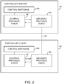
- controller server 18 and controller client 30 may communicate over network path 66 using network protocol stacks such as network protocol stack 58 and network protocol stack 60.
- Stacks 58 and 60 may be, for example Linux TCP/IP stacks or the TCP/IP stack in the VxWorks operating system (as examples).
- Path 66 may be, for example, a path that supports a network connection between switch 14 and external equipment (e.g., network path 16 of FIG. 1 ) or may be a backbone path in a rack-based system. Arrangements in which path 66 is a network path such as path 16 are sometimes described herein as an example.
- Control protocol stack 56 serves as an interface between network protocol stack 58 and control software 54.
- Control protocol stack 62 serves as an interface between network protocol stack 60 and control software 64.
- control protocol stacks 56 generate and parse control protocol messages (e.g., control messages to activate a port or to install a particular flow table entry into flow table 28).
- a network connection is formed over the link between controller server 18 and controller client 30.
- Controller server 18 and controller client 30 can communicate using a Transmission Control Protocol (TCP) or User Datagram Protocol (UDP) over Internet Protocol (IP) network connection.
- TCP Transmission Control Protocol
- UDP User Datagram Protocol
- IP Internet Protocol
- Examples of control protocols that may be used when communicating between controller server 18 and controller clients 30 over the network connection include SNMP and OpenFlow protocol stack version 1.0.0 (as examples).
- Flow table 28 contains flow table entries (e.g., rows in the table) that have multiple fields (sometimes referred to as header fields).
- the fields in a packet that has been received by switch 14 can be compared to the fields in the flow table.
- Each flow table entry may have associated actions. When there is a match between the fields in a packet and the fields in a flow table entry, the corresponding action for that flow table entry may be taken.
- table 28 may have flow table entries (rows) 68. Each flow table entry may be associated with header 70, action 72, and statistics 74. Headers 70 may each include multiple header fields 76. The action in each flow table entry indicates what action switch 14 is to perform on the packet when a match is detected between the fields in the packet and the corresponding fields in the header of that flow table entry. Switch 14 may maintain statistical data in the statistics portion of flow table 28 that can be queried by controller server 18 when it is desired to obtain information on the performance of switch 14.
- the header fields in header 70 may include the following fields: ingress port (i.e., the identity of the physical port in switch 14 through which the packet is being received), Ethernet source address, Ethernet destination address, Ethernet type, virtual local area network (VLAN) identification (sometimes referred to as a VLAN tag), VLAN priority, IP source address, IP destination address, IP protocol, IP ToS (type of service) bits, Transport source port / Internet Control Message Protocol (ICMP) Type (sometimes referred to as source TCP port), and Transport destination port / ICMP Code (sometimes referred to as destination TCP port).
- VLAN virtual local area network
- ICMP Internet Control Message Protocol
- ICMP Internet Control Message Protocol
- Transport destination port / ICMP Code sometimes referred to as destination TCP port
- Other fields may be used if desired. For example, a network protocol field and a protocol port field may be used.
- Each flow table entry is associated with zero or more actions that dictate how the switch handles matching packets. If no forward actions are present, the packet is preferably dropped.
- the actions that may be taken by switch 14 when a match is detected between packet fields and the header fields in a flow table entry may include the following actions: forward (e.g., ALL to send the packet out on all interfaces, not including the incoming interface, CONTROLLER to encapsulate and send the packet to the controller server, LOCAL to send the packet to the local networking stack of the switch, TABLE to perform actions in flow table 28, IN_PORT to send the packet out of the input port, NORMAL to process the packet with a default forwarding path that is supported by the switch using, for example, traditional level 2, VLAN, and level 3 processing, and FLOOD to flood the packet along the minimum forwarding tree, not including the incoming interface).
- forward e.g., ALL to send the packet out on all interfaces, not including the incoming interface
- CONTROLLER to encapsulate and send the packet to the controller
- Additional actions that may be taken by switch 14 include: an enqueue action to forward a packet through a queue attached to a port and a drop action (e.g., to drop a packet that matches a flow table entry with no specified action).
- Modify-field actions may also be supported by switch 14. Examples of modify-field actions that may be taken include: Set VLAN ID, Set VLAN priority, Strip VLAN header, Modify VLAN tag, Modify Ethernet source MAC (Media Access Control) address, Modify Ethernet destination MAC address, Modify IPv4 source address, Modify IPv4 ToS bits, Modify transport destination port.
- the modify-field actions may be used in rewriting portions of network packets that match the flow table entry.
- FIG. 4 is an illustrative flow table having three flow table entries.
- the entries include fields with wildcards (e.g., "*" symbols). When a wildcard is present in a particular field, all incoming packets will be considered to form a "match" with respect to the field, regardless of the particular value of the field in the incoming packet. If desired, one or more fields of the flow table entries may include partial wildcarding. Additional fields may match additional packet information (e.g., packet header information of network packets).
- the entry of the first row of the FIG. 4 table directs the switch in which the flow table entry is operating to perform Ethernet switching. In particular, incoming packets with matching Ethernet destination addresses are forwarded to port 3.
- the entry of the second row of table of FIG. 4 illustrates how a switch may be configured to perform internet routing (i.e., packets are forwarded based on their destination IP address).
- the third row of the table of FIG. 4 contains an entry that illustrates how a switch may be configured to perform firewalling.
- a packet is received that has a destination IP port value of 80, that packet is dropped (i.e., the switch is configured to serve as a firewall that blocks port 80 traffic).
- Flow table entries of the type shown in FIG. 4 may be loaded into a switch 14 by controller server 18 during system setup operations or may be provided to a switch 14 from controller server 18 in real time in response to receipt and processing of packets at controller server 18 from switches such as switch 14.
- each switch can be provided with appropriate flow table entries to form a path through the network (e.g., each switch may be provided with respective flow table entries for that switch or common flow table entries may be sent to multiple switches).
- switch 14 receives a packet on one of its ports (e.g., one of input-output ports 34 of FIG. 1 ).
- switch 14 compares the fields of the received packet to the fields of the flow table entries in the flow table 28 of that switch to determine whether there is a match.
- Some fields in a flow table entry may contain complete values (e.g., complete addresses).
- Other fields may contain wildcards (i.e., fields marked with the "don't care” wildcard character of "*").
- Yet other fields may have partially complete entries (e.g., a partial address that is partially wildcarded).
- Some fields may use ranges (e.g., by restricting a TCP port number to a value between 1 and 4096) and in effect use the range to implement a type of partial wildcarding.
- switch 14 can take into account whether or not each field in the flow table entry contains a complete value without any wildcarding, a partial value with some wildcarding, or a wildcard character (i.e., a completely wildcarded field).
- switch 14 may send the packet to controller server 18 over link 16 (step 84).
- switch 14 may perform the action that is associated with that flow table entry and may update the counter value in the statistics field of that flow table entry (step 82). Processing may then loop back to step 78, so that another packet may be processed by switch 14, as indicated by line 86.
- FIG. 6 is a diagram of an illustrative network 100 in which switches may be controlled by a controller 18.
- Controller 18 may be a controller server or a distributed controller implemented across multiple computing devices.
- network 100 may include switches C1, C2, C3, E1, E2, E3, E4, and E5.
- Controller 18 may be coupled to the switches of network 100 via control paths 66.
- Controller 18 may control the switches using control paths 66 (e.g., by providing flow table entries such as flow table entries 68 of FIG. 3 ).
- Switches include ports to which other network devices such as switches and end hosts are connected.
- switch E1 includes ports P1-P6,
- switch E2 includes ports P1-P6,
- switch E3 includes ports P1, P4, P5, and P6,
- switch E4 includes ports P1, P2, P4, P5, and P6.
- Network 100 may include end hosts such as end hosts EH1, EH2, EH3, EH4, EH5, and EH6 that are coupled to ports of the switches of network 100.
- Switches that are directly coupled to end hosts may sometimes be referred to as edge switches, whereas switches that merely interconnect other switches and are not directly coupled to the end hosts may be referred to as core switches. In the example of FIG.
- switches E1, E2, E3, E4, and E5 are edge switches, because they are coupled to end hosts.
- Switches C1, C2, and C3 are core switches, because switches C1, C2, and C3 interconnect edge switches E1, E2, E3, E4, and E5 and are not directly coupled to end hosts.
- Core switches such as switches C1, C3, and C2 may couple network 100 to other networks 102 (e.g., other networks including switches and end hosts).
- the example of FIG. 6 in which edge switches are directly coupled to core switches is merely illustrative. If desired, additional switches may be interposed between the edge and core switches.
- Network 100 may include client switches such as switches C1, C2, C3, E1, E2, E3, E4, and E5 that are controller by controller 18 and may, for example, include non-client switches that are not controller by controller 18.
- switches may be implemented using computing equipment of network racks.
- switches in network 100 may be implemented using computing equipment such as a line card of a corresponding network rack.
- Software switches on the network rack may sometimes be referred to as hypervisor switches.
- Hypervisor switches may be implemented using dedicated circuitry or using software on discrete computing equipment (e.g., on a line card). However, such software switches are coupled to the rest of the network by cables plugged into dedicated physical ports of the computing equipment on which the software switch is implemented.
- controller 18 can efficiently control a network of switches, particularly in scenarios where large numbers of switches are formed on the network.
- the network topology may be modified by a network administrator or due to device failure.
- the network modifications may potentially result in invalid configurations at the controller and inefficient packet routing or packet loss in the network.
- controller 18 may inject test packets into network 100 to perform debugging.
- injecting test packets into the network may undesirably increase traffic load on the network and may not be fully characteristic of how the network performs during normal packet forwarding operations.
- controller 18 may actively monitor the switches in network 100 for performing network debugging (debug) operations on network 100 in real time. Controller 18 may perform debugging operations on network 100 by providing the switches in the network with debug table entries for use in dedicated debugging tables in addition to flow table entries for use in flow tables implemented on the switches.
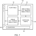
- FIG. 7 is an illustrative block diagram of a switch 130 such as a physical or hypervisor switch.
- Switch 130 may, for example, be an edge switch such as edge switch E1, E2, E3, or E4 of FIG. 6 or may be a core switch such as switches C1, C2, or C3.
- switch 130 may include ports such as ports P1, P2, P3, P4, P5, P6, etc.
- Switch 130 may include flow tables for routing network packets through network 100 (e.g., from a packet source to a packet destination) such as flow table 80 (e.g., a flow table such as flow table 28 of FIG. 3 ).
- Switch 130 may include debugging tables that are separate from flow tables 80 such as ingress debug table 82 and egress debug table 84.
- Switch 130 may include switching circuitry such as switching fabric 84 and one or more counters 88 (e.g., counting modules that implement one or more hardware and/or software counters).
- Flow table 80 may include L2 forwarding modules (e.g., entries that match Ethernet address headers of incoming packets) and/or L3 forwarding modules (e.g., entries that match IP address headers of incoming packets).
- flow table 80 may include any desired fields for matching incoming network packets that direct switch 80 to route the network packets to an appropriate packet destination in network 100 (e.g., to an appropriate port).
- Switching fabric 84 may be configured to route the network packets to the appropriate port (e.g., based on determinations made in flow table module 80) so that network packets are forwarded to a desired portion of network 100.
- a network packet received at one of the switch ports may be processed by flow table module 80 in determining how to forward the network packet.
- flow table 80 may be controlled by controller 18 (E.g., based on flow table entries in table 80).
- the entries in flow table 80 may be generated by controller 18 based on desired network policies for network 100 (e.g., desired packet routing rules, access control lists, or other network policies) for controlling packet forwarding throughout network 100.
- Debug tables 82 and 86 may be generated by controller 18 and provided to switch 130 for performing debugging operations on network 100. Debug tables 82 and 86 may be provided concurrently with flow table entries in flow table 80, during set up of network 100, when an administrator or user of controller 18 desires to initiate or perform debugging operations on the network, or at any other desired time. Debug tables on switch 130 may include flow table entries that match network packets received from flow table 80 (e.g., network packets may first be matched on flow table 80 and then may subsequently be matched on debug table 82).
- the debug tables implemented on switch 130 may be defined herein as flow tables of debug table entries (e.g., flow table entries specifically generated for performing debugging operations) that match on received network packets, where the action field of the debug table entries specify that one or more of counters 88 are to be incremented and/or that direct switch 130 to forward the received network packet (or a copy of the received network packet) to controller 18.
- debug tables 82 and 86 do not contain action fields associated with forwarding network packets through network 100 (e.g., from a packet source to a packet destination).
- the debug tables on switch 130 may increment counters 88 for use in debugging network 100 when a network packet matches on a debug table entry in table 82 or 86 and may, if desired, provide the network packets to controller 18 for analysis by controller 18 (e.g., for debugging network 100).
- Debug table 82 may be used to increment counters for ingress packets and/or provide the ingress network packets (e.g., packets received from flow table 80 and provided to an input of switching fabric 84) to controller 18, whereas debug table 84 may be used to increment counters for egress packets (e.g., packets outputted by switching fabric 84 for transmission from switch 130) and/or provide the egress packets to controller 18.
- Debug tables 82 and 86 may be separate and distinct from flow tables 80 (e.g., flow tables 80 may be associated with network forwarding operations without performing debugging operations whereas debug tables 82 and 86 may be used to perform debugging operations without performing network forwarding of received network packets).
- Modules 80, 82, and 86 may be implemented using respective dedicated circuitry, may be implemented using shared dedicated circuitry, or may be implemented using software on processing circuitry. For example, these modules may be implemented using packet processing software 26 of FIG. 1 and/or packet processing circuitry 32 and may perform functions based on control messages (e.g., flow table entries) provided by a controller. Controller 18 may generate debug table entries for switch 130 to control switch 130 to perform desired debugging operations.
- control messages e.g., flow table entries
- FIG. 8 is an illustrative debug table entry that controller 18 may generate and provide to switch 130 for performing network debugging operations.
- flow table entry 83 may include the MAC address of end host EH1 in a source MAC address field and the MAC address of end host EH2 in a destination MAC address field (e.g., debug table entry 83 may be generated by controller 18 to debug a portion of network 100 between end hosts EH1 and EH2).
- Debug table entry 83 may match on all packets having source MAC address MACEH1 and destination MAC address MACEH2 and may increment one or more of counters 88 when a matching packet is received and may optionally transmit a copy of the matching packet to controller 18 via control path 66 (e.g., as specified by the action field of debug table entry 83).
- Flow table entry 83 may be provided to one or more physical or hypervisor switches in network 100 for performing debug operations.
- flow table entry 83 may be provided to switch E1.
- any network packets received by switch E1 from end host EH1 i.e., having MAC address MACEH1 and destined for end host EH2 (i.e., having MAC address MACEH2) may be routed according to a matching flow table entry in network forwarding flow table 80 (e.g., to port P2 connected to end host EH2 as directed by an appropriate entry in table 80), while counter 88 on switch E1 is incremented (and while copies of the network packets are provided to controller 18 if desired) as determined from the action field of debug table entry 83.
- the debug table entries may match on any desired packet header fields.
- controller 18 may retrieve count information from counters 88 on the switches (e.g., count information generated in response to network packets matching on entries in debug tables implemented on the switches). For example, controller 18 may periodically retrieve the count information from some or all of the switches in network 100, may retrieve the count information at a predetermined time after providing the entries to the switches, may retrieve the count information in response to determining that debugging operations on the network are needed, may retrieve the count information when instructed to be an administrator of controller 18, or at any other desired time.
- count information e.g., count information generated in response to network packets matching on entries in debug tables implemented on the switches. For example, controller 18 may periodically retrieve the count information from some or all of the switches in network 100, may retrieve the count information at a predetermined time after providing the entries to the switches, may retrieve the count information in response to determining that debugging operations on the network are needed, may retrieve the count information when instructed to be an administrator of controller 18, or at any other desired time.
- switches 130 may periodically transmit count information to controller 18, may transmit count information to controller 18 when an instruction to transmit the count information is received from controller 18, may transmit the count information when it is determined that debugging operations are needed, or may transmit the count information at any other desired time.
- Counters 88 may include one or more individual counters that can each be incremented when packets match on debug table entries on the switch.
- counters 88 may include a first counter and a second counter.
- Debug table entries implemented on the switch may specify a particular counter to increment when a matching packet is received.
- Counters 88 may store a count value corresponding to the number of counts N that have been incremented and/or may store a value dN/dT corresponding to the rate of counts (e.g., sometimes referred to herein as count rate values) that have been incremented (e.g., the increase in count value over time).
- Controller 18 may retrieve the count values or count rate values from switch 130.
- the count values and count rate values may be indicative of how quickly one or more of counters 88 are incrementing (e.g., indicative of how many network packets are received that match on corresponding debug table entries).
- controller 18 may continuously or periodically retrieve count values N from counters 88 and may compute count rate values dN/dT based on the retrieved count values N.
- Controller 18 may process the counter information for performing debug operations on network 100. For example, controller 18 may monitor the counter information from one or more switches to determine whether network packets are being lost or are taking incorrect paths through network 100.
- controller 18 may determine whether network packets are taking incorrect (undesired) routes through network 100 or whether packet loss is occurring (e.g., whether packets are being undesirably dropped in the network).
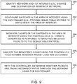
- FIG. 9 shows a flow chart of illustrative steps that may be performed by controller 18 to monitor counters 88 on the switches in network 100 for determining whether packet loss is occurring or whether packets are taking incorrect paths through the network.
- controller 18 may identify a network area of interest on which to perform the debugging operations. For example, controller 18 may identify a source and destination (e.g., two end hosts) or a region of network 100 (e.g., a set of switches and/or end hosts that may or may not be adjacent in the network) as the area of interest. In the example shown in FIG. 6 , controller 18 may select network region 70 (as indicated by dashed lines) as the area of interest on which to perform the debugging operations. The scenario where controller 18 performs debugging operations on region 70 of network 100 of FIG. 6 is described herein as an example. In general, controller 18 may perform debugging generations on any desired region of any desired network of switches.
- a source and destination e.g., two end hosts
- a region of network 100 e.g., a set of switches and/or end hosts that may or may not be adjacent in the network
- controller 18 may select network region 70 (as indicated by dashed lines) as the area of interest on which to perform the
- controller 18 may configure switches in area of interest 70 by providing the switches in region 70 with corresponding flow table entries.
- controller 18 may provide flow table entries 80 to the switches for performing normal network routing functions and may provide flow table entries in the form of debug tables 82 and 86 to the switches.
- the debug table entries provided to the switches may include entries that instruct the switches to increment counters 88 when a matching packet is received and/or that instruct the switches to route matching packets to controller 18.
- Controller 18 may expect network packets to flow through region of interest 70 according to the network forwarding rules implemented on flow tables 80 in the switches. For example, controller 18 may provide flow table entries to switches in region 70 that instruct packets from source end host EH1 to destination end host EH2 through switches E1, C3, and E2 (e.g., that implement a network forwarding rule that packets from end host EH1 to end host EH2 are only to be forwarded to end host EH2 through switches E1, C3, and E2). However, network packets may occasionally be lost (dropped) over region of interest 70 or may take an incorrect path through the network.
- Controller 18 may provide debug table entries that instruct the switches to increment corresponding counters 88 and controller 18 may monitor counter values on the switches in region 70 to determine whether packet loss or incorrect packet routing is occurring (e.g., to determine if packets are dropped or packets are not taking the expected forwarding path over switches E1, C3, and E2 between end hosts EH1 and EH2).
- controller 18 may monitor count values (e.g., counter values) on the switches in region 70 (e.g., counts generated in response to matching received packets to the debug table entries). For example, controller 18 may retrieve and monitor count values generated at switches E1, E2, C3, and C1 in region 70 for performing debugging operations.
- count values e.g., counter values
- controller 18 may retrieve and monitor count values generated at switches E1, E2, C3, and C1 in region 70 for performing debugging operations.
- controller 18 may analyze the monitored counts to determine whether packet loss has occurred. For example, controller 18 may compare count values received from adjacent switches in region 70 to determine whether there is a mismatch between the count values. If a mismatch is present, controller 18 may determine that packet loss has occurred between those two switches and may notify a user of controller 18 (e.g., a network administrator) of the packet loss (e.g., an alert or other notification may be provided to the user indicating that packet loss has occurred and/or indicating the switches between which the packet loss has occurred).
- a user of controller 18 e.g., a network administrator
- controller 18 may determine that packet loss has occurred between switches E1 and E2 (e.g., because there are 100 matching packets that were counted at switch E1 that were not counted at switch E2). Controller 18 may subsequently notify a user or administrator that packet loss has occurred (e.g., may send an alert to the user identifying that the packet loss has occurred, may identify the magnitude of the packet loss (e.g., 100 packets), and/or may identify switches E1 and E2 associated with the identified packet loss).
- a user or administrator may notify a user or administrator that packet loss has occurred (e.g., may send an alert to the user identifying that the packet loss has occurred, may identify the magnitude of the packet loss (e.g., 100 packets), and/or may identify switches E1 and E2 associated with the identified packet loss).
- controller 18 may analyze the monitored counts to determine whether network packets are taking incorrect paths through network 100. For example, controller 18 may measure a counter value at switch C1 corresponding to the selected network packet that was intended to be routed between end hosts EH1 and EH2 via switches E1, C3, and E2. If switch C1 generates a count value by matching a corresponding debug table entry on the selected packets from end host EH1 to end host EH2, controller 18 may thereby determine that some of the selected network packets were incorrectly routed to switch C1 instead of being forwarded along the intended path from switch E1 to switch C3 to switch E2 (e.g., controller 18 may determine that incorrect paths were taken for the packets between end host EH1 and EH2).
- controller 18 may issue a notification to a system administrator to inform the administrator of the incorrect path being taken by the packets (e.g., may alert the administrator that incorrect paths are being taken, may identify the incorrect path through switch C1 that has been taken, and/or may identify how many packets took the correct and incorrect paths).
- controller 18 may monitor counter rate values dN/dT for performing the debug operations. For example, controller 18 may define a time window dT over which a counter rate dN/dT is measured and may process and/or compare how the counter values N increment over the defined window for identifying packet loss or for performing any other desired debugging operations.
- controller 18 may perform network debug operations (e.g., by providing desired debug table entries to the switches in the network and monitoring counter values) that determine whether network paths have changed in network 100.
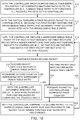
- FIG. 10 shows a flow chart of illustrative steps that may be performed by controller 18 to determine whether network paths have changed over time.
- controller 18 may provide a broad debug table entry to a selected switch in network 100 and the selected switch may implement the broad debug table entry in its corresponding debug table (e.g., one or both of debug tables 82 and 86).
- controller 18 may provide the broad debug table entry to switch E1.
- the broad debug table entry may have an action field that forwards matching packets to controller 18 and that increments a corresponding counter 88 on that switch for each matching network packet that is received and that forwards the matching packet to the controller.
- the broad debug table entry may match on all incoming network packets and may forward all received packets to the controller (e.g., the broad debug table entry may have completely wildcarded fields and an action field to increment a corresponding counter 88 and to send the matching packet to controller 18).
- the selected switch may forward a first received network packet to controller 18 (e.g., because the first packet matches on the broad debug table entry).
- the selected switch may increment a first counter 88 associated with the broad debug table entry upon matching of the first received network packet to the broad debug table entry.
- controller 18 may receive the first network packet from the selected switch and may generate a narrower debug table entry that matches the first received packet with a higher priority than the broad debug table entry.
- Debug table entries implemented on the switches in network 100 may have corresponding priority fields that indicate a priority for matching the entries to network packets. For example, two debug table entries that match on the header fields of the same network packet may have two different corresponding action fields. In this case, the action of the debug table entry having the higher priority (e.g., as indicated by a priority field in the debug table entries) may be performed.
- the narrower debug table entry may, for example, match on the header fields of the network packet that was routed to controller 18 at step 212 and may match on the switch port over which the packet was received by the selected switch.
- the packet received at step 212 may have a source MAC address MACEH1 and a destination MAC address MACEH2 and may have been received by switch E1 over port P1.
- the narrower debug table entry may match on network packets having source MAC address MACEH1, destination MAC address MACEH2, and that are received at switch E1 over port P1.
- the generated narrower debug table entry may have an action field that instructs the switch to increment a second counter 88 when a received network packet matches the narrower debug table entry, without forwarding the matching packet to controller 18.
- Controller 18 may provide the narrower debug table entry that matches the first packet to the selected switch and the selected switch may implement the narrower debug table entry in its corresponding debug table.
- the selected switch may receive a second network packet. If the second network packet matches the narrower debug table entry implemented on the selected switch (e.g., if the second packet has the same headers and was received over the same switch port as the first packet), processing may proceed to step 220 as shown by path 218. At step 220, the selected switch may increment the second counter associated with the narrower debug table entry.
- the controller may determine whether the switch is operating properly for load balancing by comparing counter rates between switches on the network. For example, controller 18 may determine whether switches E1 and E2 are load balancing in a desired manner (e.g., whether counters on each of switches E1 and E2 are incrementing in a manner consistent with the desired load balancing scheme between the two switches). If the second packet received at step 216 only matches the broad debug table entry (but does not match the narrower debug table entry), processing may proceed to step 226 as shown by path 224. At step 226, the selected switch may forward the packet to controller 18 and increment the first counter (e.g., according to the action field of the broad debug table entry).
- the controller may compare the second packet to the narrower debug table entry (e.g., the debug table entry generated to match the first packet at step 214) to determine whether a network path has changed.
- controller 18 may compare the header fields and information about the switch port over which the second packet was received to the narrower debug table entry.
- controller 18 may determine that a path (route) has changed in network 100 (e.g., because packets generated by the same source end host EH1 followed two different paths coupled to different ports on the switch). Controller 18 may subsequently notify a system administrator that a path has changed in the network (e.g., controller 18 may identify the selected switch and/or how the path has changed).
- processing may loop back to step 214 as shown by path 229 and controller 18 may continue to monitor the switches for additional path changes in the network (e.g., based on counter information associated with additional network packets that are received at the selected switch).
- the steps of FIG. 10 may, if desired, be repeated for other switches on the network to detect path changes. For example, the steps of FIG. 10 may be performed for all of the switches in network 100 or a subset of the switches in network 100. If desired, a system administrator of controller 18 may identify which switches in network 100 for which to perform path change detection operations.
- controller 18 may perform network debug operations that identify conflicts between flow table entries implemented on the switches in network 100 using the debug tables implemented on the switches.
- FIG. 11 shows a flow chart of illustrative steps that may be performed by controller 18 to identify conflicts between flow table entries in network 100. The steps of FIG. 11 may be performed, for example, by controller 18 when a desired flow table entry implemented on the switches is not functioning properly (e.g., when packets are not being routed according to the desired flow table entry) to identify any conflicts in the corresponding flow table that could prevent the flow table entry from being properly implemented by the switches.
- controller 18 may set the current priority to low (e.g., a current priority of a debug table entry to be generated).
- controller 18 may identify a flow table entry in normal network flow table 80 for testing (e.g., a flow table entry implemented on a selected switch). For example, controller 18 may select a flow table entry for testing that is not functioning properly when implemented on the switches. In this scenario, there may be a conflict between the selected flow table entries and other flow table entries implemented on the switches that is preventing the selected flow table entry from functioning properly.
- a flow table entry in normal network flow table 80 for testing e.g., a flow table entry implemented on a selected switch.
- controller 18 may select a flow table entry for testing that is not functioning properly when implemented on the switches. In this scenario, there may be a conflict between the selected flow table entries and other flow table entries implemented on the switches that is preventing the selected flow table entry from functioning properly.
- controller 18 may select a given field of the identified flow table entry for processing (e.g., a source IP address field, destination MAC address field, TCP port field, etc.). As an example, controller 18 may select the source IP address field for processing.
- a given field of the identified flow table entry e.g., a source IP address field, destination MAC address field, TCP port field, etc.
- controller 18 may generate a debug table entry for debug table 82/86 having the selected field and the current (low) priority. For example, controller 18 may generate a debug table entry having the source IP address field of the selected flow table entry. Controller 18 may provide the generated debug table entry to the selected switch.
- controller 18 may increment the current priority (e.g., to a higher priority).
- the controller may select an additional field from the selected flow table entry for processing. Processing may loop back to step 236 as shown by path 241 to generate an additional debug table entry having all currently selected and previously selected fields of the selected flow table entry and having the incremented priority.
- the additional debug table entry may have the source IP address field of the selected flow table entry, the source MAC address field of the selected flow table entry, and a higher priority than the first debug table entry.
- the additional debug table entry may be provided to the selected switch.
- each debug table entry may be generated for the selected switch that corresponds to the number of fields in the selected flow table entry, where each successive debug table entry includes the previous fields of the selected flow table entries and one additional field from the selected flow table entry.
- processing may proceed to step 244 as shown by path 242.
- Each debug table may match on incoming packets and may increment a corresponding respective counter and may forward the incoming packet to the controller when the incoming packet matches that debug table entry.
- controller 18 may identify information about which counters on the switch are incrementing and may identify a flow table field in the selected flow table entry having a conflict with other flow table entries on the selected switch based on the identified counter information. For example, the debug table entry corresponding to the first counter value that is incremented may identify the field in which the conflict exists (e.g., the field in which the conflict exists may be the additional field of the last debug table entry that did not increment a corresponding counter). Controller 18 may notify a system administrator of the flow table field that caused the conflict (e.g., so the system administrator may generate new flow table entries that resolve the conflict).
- controller 18 may perform network debug operations to identify excessively large data flows (e.g., so-called "elephant flows") between two switches in network 100.
- FIG. 12 shows a flow chart of illustrative steps that may be performed by controller 18 to identify elephant flows in the network.
- controller 18 may generate and provide a broad debug table entry with low priority that matches all received packet flows to the switches in network 100 (e.g., a debug table entry having all wildcarded matching fields).
- controller 18 may monitor the rate of increase dN/dT of counters on the switches. For example, controller 18 may retrieve counter data from first and second selected switches in network 100 and may monitor the rate of increase of the counters (e.g., controller 18 may monitor count rate values dN/dT of a first counter 88 from switches E1 and E2 that are associated with the broad debug table entry).
- controller 18 may select the broad debug table entry.
- controller 18 may partition the selected debug table entry into two or more narrower debug table entries having a higher priority and each having its own associated counter 88 at each of the selected switches (e.g., controller 18 may perform a binary search operation or may divide the broader entry into two or more narrower debug table entries). Controller 18 may provide the narrower debug table entries to the selected switches. For example, if the broad debug table entry matches packets on a range of source IP addresses such as IP addresses IP 0 - IP 100 , controller 18 may partition the broad debug table entry into a first narrower debug table entry that matches source IP addresses IP 0 - IP 50 and a second narrower debug table entry that matches source IP addresses IP 51 - IP 100 .
- the first and second narrower debug table entries may be provided with a higher priority than the broad debug table entry and may increment respective counters 88 (e.g., second and third counters) when a received packet matches the associated narrower debug table entry (e.g., a higher priority than the low priority set at step 250).
- respective counters 88 e.g., second and third counters
- controller 18 may retrieve counter information (e.g., from the second and third counters) associated with the narrower debug table entries from one or both of the selected switches and may identify which narrower debug table entry has a count that is increasing at a greater rate than the other narrower debug table entries. For example, a second counter 88 associated with the first narrower debug table entry that matches on IP addresses IP 0 - IP 50 (e.g., a counter that increments when a received packet matches the first narrower debug table entry) may increase at a first rate and a third counter associated with the second narrower debug table entry that matches on IP addresses IP 51 - IP 100 may increase at a second rate that is greater than the first rate. Processing may subsequently proceed to step 262 as shown by path 260.
- counter information e.g., from the second and third counters
- controller 18 may select the identified narrower debug table entry. Processing may subsequently loop back to step 256 as shown by path 264 to partition the identified narrower debug table entry into even narrower debug table entries for processing. Once all possibilities for narrowing the debug table entries have been exhausted, processing may proceed to step 268 as shown by path 266.
- controller 18 may determine whether an elephant flow exists between switches in the network (e.g., between the selected first and second switches) based on the monitored counter values at the switches. If the narrowest debug table entries all have similar counter rates, controller 18 may determine that no elephant flow exists (e.g., controller 18 may determine that there are many smaller, so-called "mice flows" between the switches but no excessive elephant flows).
- controller 18 may identify an elephant flow corresponding to that debug entry and may notify a system administrator of the elephant flow (e.g., and may provide information to the administrator about the elephant flow such as the switches between which the elephant flow is located, the magnitude of the elephant flow, or the matching fields associated with the elephant flow).
- controller 18 may identify that an elephant flow exists between the selected switches in the network for source IP address IP 2 .
- FIG. 13 shows an example of broad and narrow debug table entries that may be generated at controller 18 for detecting elephant flows in the network.
- broad debug table entry 300 may match all incoming packets (e.g., all source and destination IP and MAC addresses, etc.) and may increment a first counter with a first priority.
- Controller 18 may partition entry 300 into two narrower entries 302 (e.g., while processing step 256 of FIG. 11 ), where a first of the narrower entries matches a first range of IP addresses 0.0.0.0 - 128.0.0.0 and a second of the narrower entries matches a second range of IP addresses 128.0.0.0 - 255.255.255.255.255.
- Each narrower entry may increment a respective counter when a matching packet is received and may have a priority 2 that is higher than the priority of broad entry 300. Controller 18 may monitor counters 2 and 3 to determine which of the narrower entries to further partition for identifying the elephant flows. In this way, controller 18 may identify elephant flows that may be associated with inefficiencies in packet forwarding across network 100.
- FIG. 13 is merely illustrative and, if desired, any header fields may be used for partitioning to determine whether elephant flows exist in the network.
- a method of using a controller that controls switches in a network includes with the controller, providing debug table entries having matching information to the switches, the debug table entries instruct the switches to increment corresponding counters in response to receiving network packets that match the matching information, with the controller, retrieving count information from the switches that were generated by the corresponding counters on the switches, and with the controller, performing debugging operations on the network based on the retrieved count information.
- the method includes with the controller, identifying network policy rules associated with forwarding network packets through the network over the switches, and with the controller, providing flow table entries to the switches that implement the identified network rules.
- performing the debugging operations includes selecting a given one of the flow table entries, and identifying conflicts between different matching fields of the selected flow table entry based on the retrieved count information.
- performing the debugging operations includes determining whether elephant packet flows exist between a selected pair of switches in the network based on the retrieved count information.
- determining whether the elephant packet flows exist between the selected pair of switches includes with the controller, providing a broad debug table entry having a first priority to first and second switches, the broad debug table entry matches a set of network packets, and with the controller, partitioning the broad debug table entry into at least first and second narrow debug table entries that match respective first and second subsets of the set of network packets.
- determining whether the elephant packet flows exist between the selected pair of switches includes with the controller, providing each of the first and second switches with the first and second narrow debug table entries, the first narrow debug table entry instructs the first switch to increment a first counter and instructs the second switch to increment a second counter, and the second narrow debug table entry instructs the first switch to increment a third counter and the second switch to increment a fourth counter, with the controller, receiving the first and second counter values from the first switch and the third and fourth counter values from the second switch, and with the controller, determining whether the elephant flow exists between the first and second switches based on the received first, second, third, and fourth counter values.
- performing the debugging operations includes determining whether the switches are performing desired load balancing operations based on the retrieved count information.
- performing the debugging operations includes determining whether a network path between the switches has changed over time based on the retrieved count information.
- performing the debugging operations includes determining whether network packet loss has occurred between a pair of switches in the network based on the retrieved count information.
- performing the debugging operations includes determining whether network packets are taking undesired paths through the network based on the retrieved count information.
- a method of using a controller that controls switches in a network having end hosts that are coupled to the switches includes with the controller, directing packet forwarding through the network by providing at least one switch in the network with entries for a flow table implemented on the switch, and with the controller, performing network debugging operations by providing the at least one switch with debug table entries for a debug table implemented on the switch that is separate from the flow table, each debug table entry includes matching information and instructs the switch to increment a corresponding counter in response to receiving a network packet that matches the matching information.
- providing the at least one switch with the debug table entries includes providing the switch with egress debug table entries for an egress debug table implemented on the switch and ingress debug table entries for an ingress debug table implemented on the switch.
- performing the network debugging operations includes providing a broad debug table entry to the at least one switch, the broad debug table entry instructs the switch to increment a first counter in response to receiving a first network packet that matches the broad debug table entry, receiving the first network packet from the switch, and providing a narrow debug table entry to the switch, the narrow debug table entry includes narrower matching information than the broad debug table entry, the narrow debut table matches the first network packet, and the narrow debug table entry instructs the switch to increment a second counter in response to receiving a second network packet that matches the narrow debug table entry.
- performing the network debugging operations includes retrieving count information generated by the second counter on the switch, and determining whether the switch is operating properly for load balancing based on the retrieved count information.
- performing the network debugging operations includes receiving a second packet from the switch that matches the broad debug table entry without matching the narrow debug table entry, and comparing the received second packet to the narrow debug table entry to determine whether a path has changed in the network.
- performing the network debugging operations includes selecting an entry from the flow table on the at least one switch for debugging, selecting a first header field of the selected entry, and generating a first debug table entry for the at least one switch, the first debug table entry has a first priority, matches only the selected first header field, and instructs the at least one switch to increment a first counter value.
- performing the network debugging operations includes selecting a second header field from the selected entry that is different from the first header field, generating a second debug table entry for the switch, the second debug table entry has a second priority that is greater than the first priority, matches the first and second selected header fields, and instructs the at least one switch to increment a second counter value that is different from the first counter value, retrieving the first and second counter values from the at least one switch, and identifying a header field from the selected entry that conflicts with other header fields in the selected entry based at least partly on the retrieved first and second counter values.
- a method of using a controller that controls switches in a network includes with the controller, identifying an area of interest on the network, with the controller, providing debugging table entries for debugging tables implemented on switches in the identified area of interest, the debugging table entries instruct the switches to increment corresponding counter values when the switches receive a network packet that matches at least one of the debugging table entries, with the controller, retrieving the corresponding counter values from the switches in the identified area of interest, and with the controller, debugging the switches in the identified area of interest based on the retrieved counter values.
- the method includes with the controller, retrieving a first counter value from a first switch in the area of interest, a second counter value from a second switch in the area of interest, and a third counter value from a third switch in the area where a first, and with the controller, determining whether network packets are taking incorrect paths through the area of interest based on the first, second, and third counter values.
- the method includes with the controller, retrieving a first counter value from a first switch in the area of interest and a second counter value from a second switch in the area of interest, and with the controller, determining whether packet loss has occurred in the area of interest based on the retrieved first and second counter values.
- the method includes with the controller, identifying network policies associated with forwarding network packets through the network, and with the controller, providing flow table entries to the switches in the area of interest that implement the identified network policies, the flow table entries are different from the debugging table entries.
- the method includes with the controller, determining, based on the retrieved counter values, whether network packets are taking network paths through the area of interest that are not identified by the flow table entries.
Landscapes
- Engineering & Computer Science (AREA)
- Computer Networks & Wireless Communication (AREA)
- Signal Processing (AREA)
- Environmental & Geological Engineering (AREA)
- Data Mining & Analysis (AREA)
- Data Exchanges In Wide-Area Networks (AREA)
Claims (13)
- Verfahren zur Verwendung eines Steuergeräts (18), das Schalter (14) in einem Netzwerk (10) steuert, wobei das Verfahren umfasst:mit dem Steuergerät (18) Bereitstellen von Debug-Tabelleneinträgen (83) mit Abgleichinformationen für die Schalter (14), wobei die Debug-Tabelleneinträge (83) die Schalter (14) anweisen, entsprechende Zählwerke (88), in Abhängigkeit vom Empfang von Netzwerkpaketen zu inkrementieren, die zu den Abgleichinformationen passen,mit dem Steuergerät (18) Abrufen von Zählerinformationen von den Schaltern (14), die durch die entsprechenden Zählwerke (88) an den Schaltern (14) erzeugt wurden, undmit dem Steuergerät (18) Durchführen von Debugging-Operationen am Netzwerk auf Basis der abgerufenen Zählerinformationen, wobei ein Durchführen der Debugging-Operationen umfasst:
Bestimmen, ob zwischen einem ausgewählten Paar Schalter (14) im Netzwerk (10) ein Elefanten-Paketstrom vorliegt, auf Basis der abgerufenen Zählerinformationen, wobei ein Bestimmen, ob zwischen dem ausgewählten Paar Schalter (14) der Elefanten-Paketstrom vorliegt, umfasst:mit dem Steuergerät (18) Bereitstellen eines breiten Debug-Tabelleneintrags (300) mit einer ersten Priorität für erste und zweite Schalter (14), wobei der breite Debug-Tabelleneintrag (300) zu einer Gruppe von Netzwerkpaketen passt, undmit dem Steuergerät (18) Aufteilen des breiten Debug-Tabelleneintrags (300) in mindestens erste und zweite begrenzte Debug-Tabelleneinträge (302), die zu jeweiligen ersten und zweiten Untergruppen der Gruppe von Netzwerkpaketen passen, um die Zählerinformationen zu erzeugen. - Verfahren nach Anspruch 1, weiter umfassend:mit dem Steuergerät (18) Identifizieren von Netzwerkrichtlinienregeln, die mit einem Weiterleiten von Netzwerkpaketen durch das Netzwerk (10) über die Schalter (14) in Zusammenhang stehen, undmit dem Steuergerät (18) Bereitstellen von Flusstabelleneinträgen (68) für die Schalter (14), die die identifizierten Netzwerkregeln implementieren.
- Verfahren nach Anspruch 2, wobei ein Durchführen der Debugging-Operationen umfasst:Auswählen eines gegebenen Eintrags aus den Flusstabelleneinträgen (68) undIdentifizieren von Konflikten zwischen verschiedenen Abgleichfeldern des ausgewählten Flusstabelleneintrags (68) auf Basis der abgerufenen Zählerinformationen.
- Verfahren nach Anspruch 1, wobei ein Bestimmen, ob zwischen dem ausgewählten Paar Schalter (14) Elefanten-Paketströme vorliegen, weiter umfasst:mit dem Steuergerät (18) Bereitstellen der ersten und zweiten begrenzten Debug-Tabelleneinträge (302) jeweils für den ersten und zweiten Schalter (14), wobei der erste begrenzte Debug-Tabelleneintrag (302) den ersten Schalter (14) anweist, ein erstes Zählwerk (88) zu inkrementieren, und den zweiten Schalter (14) anweist, ein zweites Zählwerk (88) zu inkrementieren, und wobei der zweite begrenzte Debug-Tabelleneintrag (302) den ersten Schalter (14) anweist, ein drittes Zählwerk (88) zu inkrementieren, und den zweiten Schalter, ein viertes Zählwerk (88) zu inkrementieren,mit dem Steuergerät (18) Empfangen der ersten und zweiten Zählerwerte vom ersten Schalter (14) und der dritten und vierten Zählerwerte vom zweiten Schalter (14), undmit dem Steuergerät (18) Bestimmen, ob zwischen dem ersten und zweiten Schalter (14) der Elefantenstrom vorliegt, auf Basis der empfangenen ersten, zweiten, dritten und vierten Zählerwerte.
- Verfahren nach Anspruch 1, wobei ein Durchführen der Debugging-Operationen umfasst:
Bestimmen, ob die Schalter (14) gewünschte Lastausgleichsoperationen durchführen, auf Basis der abgerufenen Zählerinformationen. - Verfahren nach Anspruch 1, wobei ein Durchführen der Debugging-Operationen umfasst:
Bestimmen, ob ein Netzwerkpfad zwischen den Schaltern (14) sich mit der Zeit verändert hat, auf Basis der abgerufenen Zählerinformationen. - Verfahren nach Anspruch 1, wobei ein Durchführen der Debugging-Operationen umfasst:
Bestimmen, ob ein Netzwerkpaketverlust zwischen einem Schalterpaar (14) im Netzwerk aufgetreten ist, auf Basis der abgerufenen Zählerinformationen. - Verfahren nach Anspruch 1, wobei ein Durchführen der Debugging-Operationen umfasst:
Bestimmen, ob Netzwerkpakete ungewollte Pfade durch das Netzwerk (10) nehmen, auf Basis der abgerufenen Zählerinformationen. - Verfahren nach Anspruch 1, wobei die Debug-Tabelleneinträge (83) Ausgangs-Debug-Tabelleneinträge für eine Ausgangs-Debug-Tabelle (86), die auf den Schaltern (14) implementiert ist, und Eingangs-Debug-Tabelleneinträge für eine Eingangs-Debug-Tabelle (82), die auf den Schaltern (14) implementiert ist, umfassen.
- Verfahren nach Anspruch 3, wobei ein Identifizieren der Konflikte zwischen verschiedenen Abgleichfeldern des ausgewählten Flusstabelleneintrags (68) auf Basis der abgerufenen Zählerinformationen umfasst:Auswählen eines ersten Header-Felds (70) des ausgewählten Flusstabelleneintrags (68) undErzeugen eines ersten Debug-Tabelleneintrags (83) für mindestens einen der Schalter (14), wobei der erste Debug-Tabelleneintrag (83) eine erste Priorität aufweist, nur zum ausgewählten ersten Header-Feld (70) passt und den mindestens einen der Schalter (14) anweist, einen ersten Zählerwert zu inkrementieren.
- Verfahren nach Anspruch 10, wobei ein Identifizieren der Konflikte zwischen verschiedenen Abgleichfeldern des ausgewählten Flusstabelleneintrags (68) auf Basis der abgerufenen Zählerinformationen weiter umfasst:Auswählen eines zweiten Header-Felds (70) aus dem ausgewählten Flusstabelleneintrag (68), das sich vom ersten Header-Feld (70) unterscheidet,Erzeugen eines zweiten Debug-Tabelleneintrags (83) für den mindestens einen der Schalter (14), wobei der zweite Debug-Tabelleneintrag (83) eine zweite Priorität aufweist, die höher ist als die erste Priorität, zum ersten und zweiten ausgewählten Header-Feld (70) passt und den mindestens einen der Schalter (14) anweist, einen zweiten Zählerwert zu inkrementieren, der sich vom ersten Zählerwert unterscheidet,Abrufen der ersten und zweiten Zählerwerte von dem mindestens einen der Schalter (14) undIdentifizieren eines Header-Felds (70) aus dem ausgewählten Flusstabelleneintrag (68), das mit anderen Header-Feldern (70) in dem ausgewählten Eintrag in Konflikt steht, mindestens teilweise auf Basis der abgerufenen ersten und zweiten Zählerwerte.
- Verfahren nach Anspruch 2, umfassend:mit dem Steuergerät (18) Identifizieren eines interessierenden Bereichs (70) im Netzwerk (10),mit dem Steuergerät (18) Bereitstellen von Debug-Tabelleneinträgen (83) für Schalter (14) im identifizierten interessierenden Bereich (70).
- Verfahren nach Anspruch 12, weiter umfassend:
mit dem Steuergerät (18) Bestimmen, auf Basis der abgerufenen Zählerinformationen, ob Netzwerkpakete Netzwerkpfade durch den interessierenden Bereich (70) nehmen, die von den Flusstabelleneinträgen (68) nicht identifiziert sind.
Applications Claiming Priority (3)
| Application Number | Priority Date | Filing Date | Title |
|---|---|---|---|
| US201462027238P | 2014-07-21 | 2014-07-21 | |
| US14/626,450 US9813312B2 (en) | 2014-07-21 | 2015-02-19 | Systems and methods for performing debugging operations on networks using a controller |
| PCT/US2015/040933 WO2016014361A1 (en) | 2014-07-21 | 2015-07-17 | Systems and methods for performing operations on networks using a controller |
Publications (2)
| Publication Number | Publication Date |
|---|---|
| EP3158694A1 EP3158694A1 (de) | 2017-04-26 |
| EP3158694B1 true EP3158694B1 (de) | 2020-03-18 |
Family
ID=55075512
Family Applications (1)
| Application Number | Title | Priority Date | Filing Date |
|---|---|---|---|
| EP15747664.9A Active EP3158694B1 (de) | 2014-07-21 | 2015-07-17 | Systeme und verfahren zur ausführung von operationen auf netzwerken unter verwendung eines steuergeräts |
Country Status (4)
| Country | Link |
|---|---|
| US (1) | US9813312B2 (de) |
| EP (1) | EP3158694B1 (de) |
| CN (1) | CN106605392B (de) |
| WO (1) | WO2016014361A1 (de) |
Families Citing this family (82)
| Publication number | Priority date | Publication date | Assignee | Title |
|---|---|---|---|---|
| WO2015085576A1 (zh) * | 2013-12-13 | 2015-06-18 | 华为技术有限公司 | 地址解析协议消息的处理方法和转发器、控制器 |
| US9692684B2 (en) * | 2014-09-05 | 2017-06-27 | Telefonaktiebolaget L M Ericsson (Publ) | Forwarding table precedence in SDN |
| US9781004B2 (en) | 2014-10-16 | 2017-10-03 | Cisco Technology, Inc. | Discovering and grouping application endpoints in a network environment |
| US10108516B2 (en) * | 2015-01-29 | 2018-10-23 | Knuedge Incorporated | Affinity data collection in a computing system |
| KR102265861B1 (ko) * | 2015-03-05 | 2021-06-16 | 한국전자통신연구원 | 플로우 제어 관리방법 및 그 장치 |
| US10764162B2 (en) * | 2015-03-25 | 2020-09-01 | Gigamon Inc. | In-fabric traffic analysis |
| US10331569B2 (en) | 2016-01-05 | 2019-06-25 | Friday Harbor Llc | Packet router buffer management |
| US10484282B2 (en) * | 2016-01-12 | 2019-11-19 | International Business Machines Corporation | Interconnecting multiple separate openflow domains |
| US10574555B2 (en) * | 2016-01-28 | 2020-02-25 | Arista Networks, Inc. | Network data stream tracer |
| US11507487B2 (en) * | 2016-09-28 | 2022-11-22 | Vmware, Inc. | Control of a computing system to perform network fabric benchmark measurements |
| US10938712B2 (en) * | 2017-02-15 | 2021-03-02 | Intel Corporation | Compute node cluster based routing method and apparatus |
| US10560354B2 (en) | 2017-03-24 | 2020-02-11 | Cisco Technology, Inc. | End-to-end, in situ packet enrichment for network analytics |
| US10826788B2 (en) | 2017-04-20 | 2020-11-03 | Cisco Technology, Inc. | Assurance of quality-of-service configurations in a network |
| US10623264B2 (en) | 2017-04-20 | 2020-04-14 | Cisco Technology, Inc. | Policy assurance for service chaining |
| US10560328B2 (en) | 2017-04-20 | 2020-02-11 | Cisco Technology, Inc. | Static network policy analysis for networks |
| US10581694B2 (en) | 2017-05-31 | 2020-03-03 | Cisco Technology, Inc. | Generation of counter examples for network intent formal equivalence failures |
| US10505816B2 (en) | 2017-05-31 | 2019-12-10 | Cisco Technology, Inc. | Semantic analysis to detect shadowing of rules in a model of network intents |
| US10693738B2 (en) | 2017-05-31 | 2020-06-23 | Cisco Technology, Inc. | Generating device-level logical models for a network |
| US20180351788A1 (en) | 2017-05-31 | 2018-12-06 | Cisco Technology, Inc. | Fault localization in large-scale network policy deployment |
| US10812318B2 (en) | 2017-05-31 | 2020-10-20 | Cisco Technology, Inc. | Associating network policy objects with specific faults corresponding to fault localizations in large-scale network deployment |
| US10439875B2 (en) | 2017-05-31 | 2019-10-08 | Cisco Technology, Inc. | Identification of conflict rules in a network intent formal equivalence failure |
| US10554483B2 (en) | 2017-05-31 | 2020-02-04 | Cisco Technology, Inc. | Network policy analysis for networks |
| US10623271B2 (en) | 2017-05-31 | 2020-04-14 | Cisco Technology, Inc. | Intra-priority class ordering of rules corresponding to a model of network intents |
| US11469986B2 (en) | 2017-06-16 | 2022-10-11 | Cisco Technology, Inc. | Controlled micro fault injection on a distributed appliance |
| US10547715B2 (en) | 2017-06-16 | 2020-01-28 | Cisco Technology, Inc. | Event generation in response to network intent formal equivalence failures |
| US10574513B2 (en) | 2017-06-16 | 2020-02-25 | Cisco Technology, Inc. | Handling controller and node failure scenarios during data collection |
| US11645131B2 (en) | 2017-06-16 | 2023-05-09 | Cisco Technology, Inc. | Distributed fault code aggregation across application centric dimensions |
| US10904101B2 (en) | 2017-06-16 | 2021-01-26 | Cisco Technology, Inc. | Shim layer for extracting and prioritizing underlying rules for modeling network intents |
| US11150973B2 (en) | 2017-06-16 | 2021-10-19 | Cisco Technology, Inc. | Self diagnosing distributed appliance |
| US10587621B2 (en) | 2017-06-16 | 2020-03-10 | Cisco Technology, Inc. | System and method for migrating to and maintaining a white-list network security model |
| US10686669B2 (en) | 2017-06-16 | 2020-06-16 | Cisco Technology, Inc. | Collecting network models and node information from a network |
| US10498608B2 (en) | 2017-06-16 | 2019-12-03 | Cisco Technology, Inc. | Topology explorer |
| US10623259B2 (en) | 2017-06-19 | 2020-04-14 | Cisco Technology, Inc. | Validation of layer 1 interface in a network |
| US10554493B2 (en) | 2017-06-19 | 2020-02-04 | Cisco Technology, Inc. | Identifying mismatches between a logical model and node implementation |
| US10536337B2 (en) | 2017-06-19 | 2020-01-14 | Cisco Technology, Inc. | Validation of layer 2 interface and VLAN in a networked environment |
| US10560355B2 (en) | 2017-06-19 | 2020-02-11 | Cisco Technology, Inc. | Static endpoint validation |
| US11283680B2 (en) | 2017-06-19 | 2022-03-22 | Cisco Technology, Inc. | Identifying components for removal in a network configuration |
| US10567229B2 (en) | 2017-06-19 | 2020-02-18 | Cisco Technology, Inc. | Validating endpoint configurations between nodes |
| US10673702B2 (en) | 2017-06-19 | 2020-06-02 | Cisco Technology, Inc. | Validation of layer 3 using virtual routing forwarding containers in a network |
| US10437641B2 (en) | 2017-06-19 | 2019-10-08 | Cisco Technology, Inc. | On-demand processing pipeline interleaved with temporal processing pipeline |
| US10348564B2 (en) | 2017-06-19 | 2019-07-09 | Cisco Technology, Inc. | Validation of routing information base-forwarding information base equivalence in a network |
| US10333787B2 (en) | 2017-06-19 | 2019-06-25 | Cisco Technology, Inc. | Validation of L3OUT configuration for communications outside a network |
| US10547509B2 (en) | 2017-06-19 | 2020-01-28 | Cisco Technology, Inc. | Validation of a virtual port channel (VPC) endpoint in the network fabric |
| US10652102B2 (en) | 2017-06-19 | 2020-05-12 | Cisco Technology, Inc. | Network node memory utilization analysis |
| US10812336B2 (en) | 2017-06-19 | 2020-10-20 | Cisco Technology, Inc. | Validation of bridge domain-L3out association for communication outside a network |
| US10411996B2 (en) | 2017-06-19 | 2019-09-10 | Cisco Technology, Inc. | Validation of routing information in a network fabric |
| US10644946B2 (en) | 2017-06-19 | 2020-05-05 | Cisco Technology, Inc. | Detection of overlapping subnets in a network |
| US10805160B2 (en) | 2017-06-19 | 2020-10-13 | Cisco Technology, Inc. | Endpoint bridge domain subnet validation |
| US11343150B2 (en) | 2017-06-19 | 2022-05-24 | Cisco Technology, Inc. | Validation of learned routes in a network |
| US10528444B2 (en) | 2017-06-19 | 2020-01-07 | Cisco Technology, Inc. | Event generation in response to validation between logical level and hardware level |
| US10567228B2 (en) | 2017-06-19 | 2020-02-18 | Cisco Technology, Inc. | Validation of cross logical groups in a network |
| US10341184B2 (en) | 2017-06-19 | 2019-07-02 | Cisco Technology, Inc. | Validation of layer 3 bridge domain subnets in in a network |
| US10700933B2 (en) | 2017-06-19 | 2020-06-30 | Cisco Technology, Inc. | Validating tunnel endpoint addresses in a network fabric |
| US10432467B2 (en) | 2017-06-19 | 2019-10-01 | Cisco Technology, Inc. | Network validation between the logical level and the hardware level of a network |
| US10218572B2 (en) | 2017-06-19 | 2019-02-26 | Cisco Technology, Inc. | Multiprotocol border gateway protocol routing validation |
| US10505817B2 (en) | 2017-06-19 | 2019-12-10 | Cisco Technology, Inc. | Automatically determining an optimal amount of time for analyzing a distributed network environment |
| US10797959B2 (en) * | 2017-08-11 | 2020-10-06 | Quanta Computer Inc. | LLDP based rack management controller |
| US10587456B2 (en) | 2017-09-12 | 2020-03-10 | Cisco Technology, Inc. | Event clustering for a network assurance platform |
| US10587484B2 (en) | 2017-09-12 | 2020-03-10 | Cisco Technology, Inc. | Anomaly detection and reporting in a network assurance appliance |
| US10554477B2 (en) | 2017-09-13 | 2020-02-04 | Cisco Technology, Inc. | Network assurance event aggregator |
| US10333833B2 (en) | 2017-09-25 | 2019-06-25 | Cisco Technology, Inc. | Endpoint path assurance |
| FR3072236B1 (fr) * | 2017-10-10 | 2020-11-27 | Bull Sas | Dispositif et procede d'acquisition de valeurs de compteurs associes a une tache de calcul |
| US10771316B1 (en) * | 2017-11-30 | 2020-09-08 | Amazon Technologies, Inc. | Debugging of a network device through emulation |
| US11102053B2 (en) | 2017-12-05 | 2021-08-24 | Cisco Technology, Inc. | Cross-domain assurance |
| US10873509B2 (en) | 2018-01-17 | 2020-12-22 | Cisco Technology, Inc. | Check-pointing ACI network state and re-execution from a check-pointed state |
| US10572495B2 (en) | 2018-02-06 | 2020-02-25 | Cisco Technology Inc. | Network assurance database version compatibility |
| US10812315B2 (en) | 2018-06-07 | 2020-10-20 | Cisco Technology, Inc. | Cross-domain network assurance |
| US11019027B2 (en) | 2018-06-27 | 2021-05-25 | Cisco Technology, Inc. | Address translation for external network appliance |
| US10911495B2 (en) | 2018-06-27 | 2021-02-02 | Cisco Technology, Inc. | Assurance of security rules in a network |
| US10659298B1 (en) | 2018-06-27 | 2020-05-19 | Cisco Technology, Inc. | Epoch comparison for network events |
| US11044273B2 (en) | 2018-06-27 | 2021-06-22 | Cisco Technology, Inc. | Assurance of security rules in a network |
| US11218508B2 (en) | 2018-06-27 | 2022-01-04 | Cisco Technology, Inc. | Assurance of security rules in a network |
| US10904070B2 (en) | 2018-07-11 | 2021-01-26 | Cisco Technology, Inc. | Techniques and interfaces for troubleshooting datacenter networks |
| US10826770B2 (en) | 2018-07-26 | 2020-11-03 | Cisco Technology, Inc. | Synthesis of models for networks using automated boolean learning |
| US10616072B1 (en) | 2018-07-27 | 2020-04-07 | Cisco Technology, Inc. | Epoch data interface |
| FR3084550B1 (fr) * | 2018-07-27 | 2020-07-24 | Bcom | Procede de traitement d'un paquet de donnees, dispositif, equipement de communication et programme d'ordinateur associes |
| US11870649B2 (en) * | 2019-02-22 | 2024-01-09 | Extreme Networks, Inc. | Multi-access edge computing based visibility network |
| CN110380993B (zh) * | 2019-07-12 | 2021-09-14 | 中国电信集团工会上海市委员会 | 一种基于ovsdb的流表保护方法 |
| CN112073256B (zh) * | 2020-06-01 | 2022-07-19 | 新华三信息安全技术有限公司 | 一种丢包处理方法、装置、设备及机器可读存储介质 |
| US11368380B1 (en) * | 2020-06-01 | 2022-06-21 | Amazon Technologies, Inc. | Estimating end-to-end network packet loss |
| CN115733889B (zh) * | 2021-08-31 | 2025-05-06 | 腾讯科技(深圳)有限公司 | 一种网络转发设备的调试方法、装置、设备及存储介质 |
| US20230188443A1 (en) * | 2021-12-10 | 2023-06-15 | Arista Networks, Inc. | Packet drop analysis for networks |
Family Cites Families (22)
| Publication number | Priority date | Publication date | Assignee | Title |
|---|---|---|---|---|
| US7020166B2 (en) | 2000-10-03 | 2006-03-28 | Broadcom Corporation | Switch transferring data using data encapsulation and decapsulation |
| CN1757210A (zh) | 2003-01-15 | 2006-04-05 | 希尔纳公司 | 用于在光网络上传输分组数据的方法和装置 |
| KR20050076176A (ko) | 2004-01-19 | 2005-07-26 | 삼성전자주식회사 | IPv6 MANET망에서 외부망과의 통신을 위한 시스템및 방법 |
| US8116312B2 (en) | 2006-02-08 | 2012-02-14 | Solarflare Communications, Inc. | Method and apparatus for multicast packet reception |
| US20080189769A1 (en) | 2007-02-01 | 2008-08-07 | Martin Casado | Secure network switching infrastructure |
| JP5141512B2 (ja) | 2008-11-27 | 2013-02-13 | 富士通株式会社 | 通信制御方法及び伝送装置 |
| CN102349268B (zh) * | 2009-03-09 | 2015-11-25 | 日本电气株式会社 | OpenFlow通信系统和OpenFlow通信方法 |
| US7937438B1 (en) | 2009-12-07 | 2011-05-03 | Amazon Technologies, Inc. | Using virtual networking devices to manage external connections |
| WO2012023292A1 (en) * | 2010-08-20 | 2012-02-23 | Nec Corporation | Communication system, controller, node controlling method and program |
| US9054975B2 (en) | 2010-08-30 | 2015-06-09 | Deutsche Telekom Ag | Virtualization and replay-based system for network debugging |
| US9124515B2 (en) | 2010-11-22 | 2015-09-01 | Hewlett-Packard Development Company, L.P. | Elephant flow detection in a computing device |
| WO2012145886A1 (zh) * | 2011-04-25 | 2012-11-01 | 华为技术有限公司 | 一种基于标签的测量方法,装置和系统 |
| US8964563B2 (en) * | 2011-07-08 | 2015-02-24 | Telefonaktiebolaget L M Ericsson (Publ) | Controller driven OAM for OpenFlow |
| US8924787B2 (en) | 2012-01-24 | 2014-12-30 | Nec Laboratories America, Inc. | Network debugging |
| US8923296B2 (en) | 2012-02-23 | 2014-12-30 | Big Switch Networks, Inc. | System and methods for managing network packet forwarding with a controller |
| US9014013B2 (en) | 2012-03-16 | 2015-04-21 | Brocade Communications Systems, Inc. | Packet tracing through control and data plane operations using SNMP trap commands |
| US9184995B2 (en) * | 2012-04-11 | 2015-11-10 | Gigamon Inc. | Traffic visibility in an open networking environment |
| US8982727B2 (en) | 2012-10-22 | 2015-03-17 | Futurewei Technologies, Inc. | System and apparatus of generalized network controller for a software defined network (SDN) |
| US8964752B2 (en) * | 2013-02-25 | 2015-02-24 | Telefonaktiebolaget L M Ericsson (Publ) | Method and system for flow table lookup parallelization in a software defined networking (SDN) system |
| US9692775B2 (en) * | 2013-04-29 | 2017-06-27 | Telefonaktiebolaget Lm Ericsson (Publ) | Method and system to dynamically detect traffic anomalies in a network |
| US9137165B2 (en) * | 2013-06-17 | 2015-09-15 | Telefonaktiebolaget L M Ericsson (Publ) | Methods of load balancing using primary and stand-by addresses and related load balancers and servers |
| US9118567B2 (en) * | 2013-07-15 | 2015-08-25 | Telefonaktiebolaget L M Ericsson (Publ) | Removing lead filter from serial multiple-stage filter used to detect large flows in order to purge flows for prolonged operation |
-
2015
- 2015-02-19 US US14/626,450 patent/US9813312B2/en active Active
- 2015-07-17 CN CN201580045963.6A patent/CN106605392B/zh not_active Expired - Fee Related
- 2015-07-17 WO PCT/US2015/040933 patent/WO2016014361A1/en not_active Ceased
- 2015-07-17 EP EP15747664.9A patent/EP3158694B1/de active Active
Non-Patent Citations (1)
| Title |
|---|
| None * |
Also Published As
| Publication number | Publication date |
|---|---|
| US20160020993A1 (en) | 2016-01-21 |
| CN106605392B (zh) | 2020-01-03 |
| CN106605392A (zh) | 2017-04-26 |
| EP3158694A1 (de) | 2017-04-26 |
| US9813312B2 (en) | 2017-11-07 |
| WO2016014361A1 (en) | 2016-01-28 |
Similar Documents
| Publication | Publication Date | Title |
|---|---|---|
| US9813312B2 (en) | Systems and methods for performing debugging operations on networks using a controller | |
| EP3058681B1 (de) | Verfahren zur prüfung von netzwerken mit einer steuerung | |
| US9813323B2 (en) | Systems and methods for controlling switches to capture and monitor network traffic | |
| EP3072264B1 (de) | Verfahren zur durchführung eines netzwerkdiensteinsatzes | |
| US9935831B1 (en) | Systems and methods for controlling network switches using a switch modeling interface at a controller | |
| US10270645B2 (en) | Systems and methods for handling link aggregation failover with a controller | |
| US9654380B1 (en) | Systems and methods for determining network topologies | |
| US9185056B2 (en) | System and methods for controlling network traffic through virtual switches | |
| US8787388B1 (en) | System and methods for forwarding packets through a network | |
| US9787567B1 (en) | Systems and methods for network traffic monitoring | |
| US9008080B1 (en) | Systems and methods for controlling switches to monitor network traffic | |
| US9548900B1 (en) | Systems and methods for forwarding network packets in a network using network domain topology information | |
| EP3906643A1 (de) | Netzwerke mit mehreren schalterebenen | |
| US9356838B1 (en) | Systems and methods for determining network forwarding paths with a controller | |
| US9264295B1 (en) | Systems and methods for forwarding broadcast network packets with a controller | |
| HK1233783B (en) | Systems and methods for performing operations on networks using a controller | |
| HK1233783A1 (en) | Systems and methods for performing operations on networks using a controller | |
| Aweya | Switch/router architectures: systems with crossbar switch fabrics | |
| HK1229091A1 (en) | Method for performing network service insertion | |
| HK1229091B (en) | Method for performing network service insertion |
Legal Events
| Date | Code | Title | Description |
|---|---|---|---|
| STAA | Information on the status of an ep patent application or granted ep patent |
Free format text: STATUS: THE INTERNATIONAL PUBLICATION HAS BEEN MADE |
|
| PUAI | Public reference made under article 153(3) epc to a published international application that has entered the european phase |
Free format text: ORIGINAL CODE: 0009012 |
|
| STAA | Information on the status of an ep patent application or granted ep patent |
Free format text: STATUS: REQUEST FOR EXAMINATION WAS MADE |
|
| 17P | Request for examination filed |
Effective date: 20170120 |
|
| AK | Designated contracting states |
Kind code of ref document: A1 Designated state(s): AL AT BE BG CH CY CZ DE DK EE ES FI FR GB GR HR HU IE IS IT LI LT LU LV MC MK MT NL NO PL PT RO RS SE SI SK SM TR |
|
| AX | Request for extension of the european patent |
Extension state: BA ME |
|
| RIN1 | Information on inventor provided before grant (corrected) |
Inventor name: MAIER, GREGOR, MATHIAS Inventor name: CHIANG, KENNETH, HSINCHAO Inventor name: LANE, RICHARD, LEEGAN Inventor name: WU, XIN Inventor name: BAJPAI, RAJNEESH Inventor name: YANG, MEI Inventor name: RAMASUBRAMANIAN, SRINIVASAN Inventor name: SHERWOOD, ROBERT, W. |
|
| DAV | Request for validation of the european patent (deleted) | ||
| DAX | Request for extension of the european patent (deleted) | ||
| REG | Reference to a national code |
Ref country code: HK Ref legal event code: DE Ref document number: 1233783 Country of ref document: HK |
|
| STAA | Information on the status of an ep patent application or granted ep patent |
Free format text: STATUS: EXAMINATION IS IN PROGRESS |
|
| 17Q | First examination report despatched |
Effective date: 20190125 |
|
| RAP1 | Party data changed (applicant data changed or rights of an application transferred) |
Owner name: BIG SWITCH NETWORKS, INC. |
|
| REG | Reference to a national code |
Ref country code: DE Ref legal event code: R079 Ref document number: 602015049022 Country of ref document: DE Free format text: PREVIOUS MAIN CLASS: H04L0012803000 Ipc: H04L0012741000 |
|
| GRAP | Despatch of communication of intention to grant a patent |
Free format text: ORIGINAL CODE: EPIDOSNIGR1 |
|
| STAA | Information on the status of an ep patent application or granted ep patent |
Free format text: STATUS: GRANT OF PATENT IS INTENDED |
|
| RIC1 | Information provided on ipc code assigned before grant |
Ipc: H04L 12/24 20060101ALI20190628BHEP Ipc: H04L 12/741 20130101AFI20190628BHEP Ipc: H04L 12/721 20130101ALI20190628BHEP Ipc: H04L 12/26 20060101ALI20190628BHEP Ipc: H04L 12/803 20130101ALI20190628BHEP |
|
| INTG | Intention to grant announced |
Effective date: 20190724 |
|
| GRAJ | Information related to disapproval of communication of intention to grant by the applicant or resumption of examination proceedings by the epo deleted |
Free format text: ORIGINAL CODE: EPIDOSDIGR1 |
|
| STAA | Information on the status of an ep patent application or granted ep patent |
Free format text: STATUS: EXAMINATION IS IN PROGRESS |
|
| GRAP | Despatch of communication of intention to grant a patent |
Free format text: ORIGINAL CODE: EPIDOSNIGR1 |
|
| STAA | Information on the status of an ep patent application or granted ep patent |
Free format text: STATUS: GRANT OF PATENT IS INTENDED |
|
| INTG | Intention to grant announced |
Effective date: 20191220 |
|
| GRAS | Grant fee paid |
Free format text: ORIGINAL CODE: EPIDOSNIGR3 |
|
| GRAA | (expected) grant |
Free format text: ORIGINAL CODE: 0009210 |
|
| STAA | Information on the status of an ep patent application or granted ep patent |
Free format text: STATUS: THE PATENT HAS BEEN GRANTED |
|
| AK | Designated contracting states |
Kind code of ref document: B1 Designated state(s): AL AT BE BG CH CY CZ DE DK EE ES FI FR GB GR HR HU IE IS IT LI LT LU LV MC MK MT NL NO PL PT RO RS SE SI SK SM TR |
|
| REG | Reference to a national code |
Ref country code: GB Ref legal event code: FG4D |
|
| REG | Reference to a national code |
Ref country code: DE Ref legal event code: R096 Ref document number: 602015049022 Country of ref document: DE |
|
| REG | Reference to a national code |
Ref country code: AT Ref legal event code: REF Ref document number: 1247189 Country of ref document: AT Kind code of ref document: T Effective date: 20200415 Ref country code: IE Ref legal event code: FG4D |
|
| RAP2 | Party data changed (patent owner data changed or rights of a patent transferred) |
Owner name: BIG SWITCH NETWORKS LLC |
|
| PG25 | Lapsed in a contracting state [announced via postgrant information from national office to epo] |
Ref country code: RS Free format text: LAPSE BECAUSE OF FAILURE TO SUBMIT A TRANSLATION OF THE DESCRIPTION OR TO PAY THE FEE WITHIN THE PRESCRIBED TIME-LIMIT Effective date: 20200318 Ref country code: NO Free format text: LAPSE BECAUSE OF FAILURE TO SUBMIT A TRANSLATION OF THE DESCRIPTION OR TO PAY THE FEE WITHIN THE PRESCRIBED TIME-LIMIT Effective date: 20200618 Ref country code: FI Free format text: LAPSE BECAUSE OF FAILURE TO SUBMIT A TRANSLATION OF THE DESCRIPTION OR TO PAY THE FEE WITHIN THE PRESCRIBED TIME-LIMIT Effective date: 20200318 |
|
| REG | Reference to a national code |
Ref country code: NL Ref legal event code: MP Effective date: 20200318 |
|
| PG25 | Lapsed in a contracting state [announced via postgrant information from national office to epo] |
Ref country code: BG Free format text: LAPSE BECAUSE OF FAILURE TO SUBMIT A TRANSLATION OF THE DESCRIPTION OR TO PAY THE FEE WITHIN THE PRESCRIBED TIME-LIMIT Effective date: 20200618 Ref country code: SE Free format text: LAPSE BECAUSE OF FAILURE TO SUBMIT A TRANSLATION OF THE DESCRIPTION OR TO PAY THE FEE WITHIN THE PRESCRIBED TIME-LIMIT Effective date: 20200318 Ref country code: LV Free format text: LAPSE BECAUSE OF FAILURE TO SUBMIT A TRANSLATION OF THE DESCRIPTION OR TO PAY THE FEE WITHIN THE PRESCRIBED TIME-LIMIT Effective date: 20200318 Ref country code: HR Free format text: LAPSE BECAUSE OF FAILURE TO SUBMIT A TRANSLATION OF THE DESCRIPTION OR TO PAY THE FEE WITHIN THE PRESCRIBED TIME-LIMIT Effective date: 20200318 Ref country code: GR Free format text: LAPSE BECAUSE OF FAILURE TO SUBMIT A TRANSLATION OF THE DESCRIPTION OR TO PAY THE FEE WITHIN THE PRESCRIBED TIME-LIMIT Effective date: 20200619 |
|
| REG | Reference to a national code |
Ref country code: LT Ref legal event code: MG4D |
|
| PG25 | Lapsed in a contracting state [announced via postgrant information from national office to epo] |
Ref country code: NL Free format text: LAPSE BECAUSE OF FAILURE TO SUBMIT A TRANSLATION OF THE DESCRIPTION OR TO PAY THE FEE WITHIN THE PRESCRIBED TIME-LIMIT Effective date: 20200318 |
|
| PG25 | Lapsed in a contracting state [announced via postgrant information from national office to epo] |
Ref country code: EE Free format text: LAPSE BECAUSE OF FAILURE TO SUBMIT A TRANSLATION OF THE DESCRIPTION OR TO PAY THE FEE WITHIN THE PRESCRIBED TIME-LIMIT Effective date: 20200318 Ref country code: LT Free format text: LAPSE BECAUSE OF FAILURE TO SUBMIT A TRANSLATION OF THE DESCRIPTION OR TO PAY THE FEE WITHIN THE PRESCRIBED TIME-LIMIT Effective date: 20200318 Ref country code: SM Free format text: LAPSE BECAUSE OF FAILURE TO SUBMIT A TRANSLATION OF THE DESCRIPTION OR TO PAY THE FEE WITHIN THE PRESCRIBED TIME-LIMIT Effective date: 20200318 Ref country code: PT Free format text: LAPSE BECAUSE OF FAILURE TO SUBMIT A TRANSLATION OF THE DESCRIPTION OR TO PAY THE FEE WITHIN THE PRESCRIBED TIME-LIMIT Effective date: 20200812 Ref country code: SK Free format text: LAPSE BECAUSE OF FAILURE TO SUBMIT A TRANSLATION OF THE DESCRIPTION OR TO PAY THE FEE WITHIN THE PRESCRIBED TIME-LIMIT Effective date: 20200318 Ref country code: CZ Free format text: LAPSE BECAUSE OF FAILURE TO SUBMIT A TRANSLATION OF THE DESCRIPTION OR TO PAY THE FEE WITHIN THE PRESCRIBED TIME-LIMIT Effective date: 20200318 Ref country code: IS Free format text: LAPSE BECAUSE OF FAILURE TO SUBMIT A TRANSLATION OF THE DESCRIPTION OR TO PAY THE FEE WITHIN THE PRESCRIBED TIME-LIMIT Effective date: 20200718 Ref country code: RO Free format text: LAPSE BECAUSE OF FAILURE TO SUBMIT A TRANSLATION OF THE DESCRIPTION OR TO PAY THE FEE WITHIN THE PRESCRIBED TIME-LIMIT Effective date: 20200318 |
|
| REG | Reference to a national code |
Ref country code: AT Ref legal event code: MK05 Ref document number: 1247189 Country of ref document: AT Kind code of ref document: T Effective date: 20200318 |
|
| REG | Reference to a national code |
Ref country code: DE Ref legal event code: R097 Ref document number: 602015049022 Country of ref document: DE |
|
| PLBE | No opposition filed within time limit |
Free format text: ORIGINAL CODE: 0009261 |
|
| STAA | Information on the status of an ep patent application or granted ep patent |
Free format text: STATUS: NO OPPOSITION FILED WITHIN TIME LIMIT |
|
| PG25 | Lapsed in a contracting state [announced via postgrant information from national office to epo] |
Ref country code: DK Free format text: LAPSE BECAUSE OF FAILURE TO SUBMIT A TRANSLATION OF THE DESCRIPTION OR TO PAY THE FEE WITHIN THE PRESCRIBED TIME-LIMIT Effective date: 20200318 Ref country code: AT Free format text: LAPSE BECAUSE OF FAILURE TO SUBMIT A TRANSLATION OF THE DESCRIPTION OR TO PAY THE FEE WITHIN THE PRESCRIBED TIME-LIMIT Effective date: 20200318 Ref country code: IT Free format text: LAPSE BECAUSE OF FAILURE TO SUBMIT A TRANSLATION OF THE DESCRIPTION OR TO PAY THE FEE WITHIN THE PRESCRIBED TIME-LIMIT Effective date: 20200318 Ref country code: ES Free format text: LAPSE BECAUSE OF FAILURE TO SUBMIT A TRANSLATION OF THE DESCRIPTION OR TO PAY THE FEE WITHIN THE PRESCRIBED TIME-LIMIT Effective date: 20200318 |
|
| 26N | No opposition filed |
Effective date: 20201221 |
|
| PG25 | Lapsed in a contracting state [announced via postgrant information from national office to epo] |
Ref country code: MC Free format text: LAPSE BECAUSE OF FAILURE TO SUBMIT A TRANSLATION OF THE DESCRIPTION OR TO PAY THE FEE WITHIN THE PRESCRIBED TIME-LIMIT Effective date: 20200318 Ref country code: PL Free format text: LAPSE BECAUSE OF FAILURE TO SUBMIT A TRANSLATION OF THE DESCRIPTION OR TO PAY THE FEE WITHIN THE PRESCRIBED TIME-LIMIT Effective date: 20200318 |
|
| REG | Reference to a national code |
Ref country code: CH Ref legal event code: PL |
|
| REG | Reference to a national code |
Ref country code: BE Ref legal event code: MM Effective date: 20200731 |
|
| PG25 | Lapsed in a contracting state [announced via postgrant information from national office to epo] |
Ref country code: LI Free format text: LAPSE BECAUSE OF NON-PAYMENT OF DUE FEES Effective date: 20200731 Ref country code: LU Free format text: LAPSE BECAUSE OF NON-PAYMENT OF DUE FEES Effective date: 20200717 Ref country code: CH Free format text: LAPSE BECAUSE OF NON-PAYMENT OF DUE FEES Effective date: 20200731 |
|
| REG | Reference to a national code |
Ref country code: DE Ref legal event code: R081 Ref document number: 602015049022 Country of ref document: DE Owner name: ARISTA NETWORKS, INC., SANTA CLARA, US Free format text: FORMER OWNER: BIG SWITCH NETWORKS, INC., SANTA CLARA, CA, US Ref country code: DE Ref legal event code: R081 Ref document number: 602015049022 Country of ref document: DE Owner name: BIG SWITCH NETWORKS LLC, SANTA CLARA, US Free format text: FORMER OWNER: BIG SWITCH NETWORKS, INC., SANTA CLARA, CA, US |
|
| PG25 | Lapsed in a contracting state [announced via postgrant information from national office to epo] |
Ref country code: SI Free format text: LAPSE BECAUSE OF FAILURE TO SUBMIT A TRANSLATION OF THE DESCRIPTION OR TO PAY THE FEE WITHIN THE PRESCRIBED TIME-LIMIT Effective date: 20200318 Ref country code: BE Free format text: LAPSE BECAUSE OF NON-PAYMENT OF DUE FEES Effective date: 20200731 |
|
| PG25 | Lapsed in a contracting state [announced via postgrant information from national office to epo] |
Ref country code: IE Free format text: LAPSE BECAUSE OF NON-PAYMENT OF DUE FEES Effective date: 20200717 |
|
| REG | Reference to a national code |
Ref country code: DE Ref legal event code: R079 Ref document number: 602015049022 Country of ref document: DE Free format text: PREVIOUS MAIN CLASS: H04L0012741000 Ipc: H04L0045740000 |
|
| REG | Reference to a national code |
Ref country code: DE Ref legal event code: R081 Ref document number: 602015049022 Country of ref document: DE Owner name: ARISTA NETWORKS, INC., SANTA CLARA, US Free format text: FORMER OWNER: BIG SWITCH NETWORKS LLC, SANTA CLARA, CA, US |
|
| PG25 | Lapsed in a contracting state [announced via postgrant information from national office to epo] |
Ref country code: TR Free format text: LAPSE BECAUSE OF FAILURE TO SUBMIT A TRANSLATION OF THE DESCRIPTION OR TO PAY THE FEE WITHIN THE PRESCRIBED TIME-LIMIT Effective date: 20200318 Ref country code: MT Free format text: LAPSE BECAUSE OF FAILURE TO SUBMIT A TRANSLATION OF THE DESCRIPTION OR TO PAY THE FEE WITHIN THE PRESCRIBED TIME-LIMIT Effective date: 20200318 Ref country code: CY Free format text: LAPSE BECAUSE OF FAILURE TO SUBMIT A TRANSLATION OF THE DESCRIPTION OR TO PAY THE FEE WITHIN THE PRESCRIBED TIME-LIMIT Effective date: 20200318 |
|
| REG | Reference to a national code |
Ref country code: GB Ref legal event code: 732E Free format text: REGISTERED BETWEEN 20220505 AND 20220512 |
|
| PG25 | Lapsed in a contracting state [announced via postgrant information from national office to epo] |
Ref country code: MK Free format text: LAPSE BECAUSE OF FAILURE TO SUBMIT A TRANSLATION OF THE DESCRIPTION OR TO PAY THE FEE WITHIN THE PRESCRIBED TIME-LIMIT Effective date: 20200318 Ref country code: AL Free format text: LAPSE BECAUSE OF FAILURE TO SUBMIT A TRANSLATION OF THE DESCRIPTION OR TO PAY THE FEE WITHIN THE PRESCRIBED TIME-LIMIT Effective date: 20200318 |
|
| PGFP | Annual fee paid to national office [announced via postgrant information from national office to epo] |
Ref country code: GB Payment date: 20250529 Year of fee payment: 11 |
|
| PGFP | Annual fee paid to national office [announced via postgrant information from national office to epo] |
Ref country code: FR Payment date: 20250523 Year of fee payment: 11 |
|
| PGFP | Annual fee paid to national office [announced via postgrant information from national office to epo] |
Ref country code: DE Payment date: 20250521 Year of fee payment: 11 |