EP3158384B1 - Verfahren und vorrichtung zur ansteuerung eines akustooptischen bauteils - Google Patents
Verfahren und vorrichtung zur ansteuerung eines akustooptischen bauteils Download PDFInfo
- Publication number
- EP3158384B1 EP3158384B1 EP15730966.7A EP15730966A EP3158384B1 EP 3158384 B1 EP3158384 B1 EP 3158384B1 EP 15730966 A EP15730966 A EP 15730966A EP 3158384 B1 EP3158384 B1 EP 3158384B1
- Authority
- EP
- European Patent Office
- Prior art keywords
- acousto
- optic component
- transfer function
- main
- frequency generator
- Prior art date
- Legal status (The legal status is an assumption and is not a legal conclusion. Google has not performed a legal analysis and makes no representation as to the accuracy of the status listed.)
- Active
Links
Images


Classifications
-
- G—PHYSICS
- G01—MEASURING; TESTING
- G01J—MEASUREMENT OF INTENSITY, VELOCITY, SPECTRAL CONTENT, POLARISATION, PHASE OR PULSE CHARACTERISTICS OF INFRARED, VISIBLE OR ULTRAVIOLET LIGHT; COLORIMETRY; RADIATION PYROMETRY
- G01J3/00—Spectrometry; Spectrophotometry; Monochromators; Measuring colours
- G01J3/12—Generating the spectrum; Monochromators
- G01J3/1256—Generating the spectrum; Monochromators using acousto-optic tunable filter
-
- G—PHYSICS
- G01—MEASURING; TESTING
- G01J—MEASUREMENT OF INTENSITY, VELOCITY, SPECTRAL CONTENT, POLARISATION, PHASE OR PULSE CHARACTERISTICS OF INFRARED, VISIBLE OR ULTRAVIOLET LIGHT; COLORIMETRY; RADIATION PYROMETRY
- G01J3/00—Spectrometry; Spectrophotometry; Monochromators; Measuring colours
- G01J3/02—Details
- G01J3/06—Scanning arrangements arrangements for order-selection
-
- G—PHYSICS
- G01—MEASURING; TESTING
- G01J—MEASUREMENT OF INTENSITY, VELOCITY, SPECTRAL CONTENT, POLARISATION, PHASE OR PULSE CHARACTERISTICS OF INFRARED, VISIBLE OR ULTRAVIOLET LIGHT; COLORIMETRY; RADIATION PYROMETRY
- G01J3/00—Spectrometry; Spectrophotometry; Monochromators; Measuring colours
- G01J3/12—Generating the spectrum; Monochromators
-
- G—PHYSICS
- G02—OPTICS
- G02B—OPTICAL ELEMENTS, SYSTEMS OR APPARATUS
- G02B21/00—Microscopes
- G02B21/0004—Microscopes specially adapted for specific applications
- G02B21/002—Scanning microscopes
-
- G—PHYSICS
- G02—OPTICS
- G02B—OPTICAL ELEMENTS, SYSTEMS OR APPARATUS
- G02B21/00—Microscopes
- G02B21/16—Microscopes adapted for ultraviolet illumination ; Fluorescence microscopes
-
- G—PHYSICS
- G02—OPTICS
- G02F—OPTICAL DEVICES OR ARRANGEMENTS FOR THE CONTROL OF LIGHT BY MODIFICATION OF THE OPTICAL PROPERTIES OF THE MEDIA OF THE ELEMENTS INVOLVED THEREIN; NON-LINEAR OPTICS; FREQUENCY-CHANGING OF LIGHT; OPTICAL LOGIC ELEMENTS; OPTICAL ANALOGUE/DIGITAL CONVERTERS
- G02F1/00—Devices or arrangements for the control of the intensity, colour, phase, polarisation or direction of light arriving from an independent light source, e.g. switching, gating or modulating; Non-linear optics
- G02F1/01—Devices or arrangements for the control of the intensity, colour, phase, polarisation or direction of light arriving from an independent light source, e.g. switching, gating or modulating; Non-linear optics for the control of the intensity, phase, polarisation or colour
- G02F1/11—Devices or arrangements for the control of the intensity, colour, phase, polarisation or direction of light arriving from an independent light source, e.g. switching, gating or modulating; Non-linear optics for the control of the intensity, phase, polarisation or colour based on acousto-optical elements, e.g. using variable diffraction by sound or like mechanical waves
- G02F1/113—Circuit or control arrangements
-
- G—PHYSICS
- G02—OPTICS
- G02F—OPTICAL DEVICES OR ARRANGEMENTS FOR THE CONTROL OF LIGHT BY MODIFICATION OF THE OPTICAL PROPERTIES OF THE MEDIA OF THE ELEMENTS INVOLVED THEREIN; NON-LINEAR OPTICS; FREQUENCY-CHANGING OF LIGHT; OPTICAL LOGIC ELEMENTS; OPTICAL ANALOGUE/DIGITAL CONVERTERS
- G02F1/00—Devices or arrangements for the control of the intensity, colour, phase, polarisation or direction of light arriving from an independent light source, e.g. switching, gating or modulating; Non-linear optics
- G02F1/01—Devices or arrangements for the control of the intensity, colour, phase, polarisation or direction of light arriving from an independent light source, e.g. switching, gating or modulating; Non-linear optics for the control of the intensity, phase, polarisation or colour
- G02F1/11—Devices or arrangements for the control of the intensity, colour, phase, polarisation or direction of light arriving from an independent light source, e.g. switching, gating or modulating; Non-linear optics for the control of the intensity, phase, polarisation or colour based on acousto-optical elements, e.g. using variable diffraction by sound or like mechanical waves
- G02F1/116—Devices or arrangements for the control of the intensity, colour, phase, polarisation or direction of light arriving from an independent light source, e.g. switching, gating or modulating; Non-linear optics for the control of the intensity, phase, polarisation or colour based on acousto-optical elements, e.g. using variable diffraction by sound or like mechanical waves using an optically anisotropic medium, wherein the incident and the diffracted light waves have different polarizations, e.g. acousto-optic tunable filter [AOTF]
-
- G—PHYSICS
- G02—OPTICS
- G02F—OPTICAL DEVICES OR ARRANGEMENTS FOR THE CONTROL OF LIGHT BY MODIFICATION OF THE OPTICAL PROPERTIES OF THE MEDIA OF THE ELEMENTS INVOLVED THEREIN; NON-LINEAR OPTICS; FREQUENCY-CHANGING OF LIGHT; OPTICAL LOGIC ELEMENTS; OPTICAL ANALOGUE/DIGITAL CONVERTERS
- G02F1/00—Devices or arrangements for the control of the intensity, colour, phase, polarisation or direction of light arriving from an independent light source, e.g. switching, gating or modulating; Non-linear optics
- G02F1/29—Devices or arrangements for the control of the intensity, colour, phase, polarisation or direction of light arriving from an independent light source, e.g. switching, gating or modulating; Non-linear optics for the control of the position or the direction of light beams, i.e. deflection
- G02F1/33—Acousto-optical deflection devices
-
- G—PHYSICS
- G01—MEASURING; TESTING
- G01J—MEASUREMENT OF INTENSITY, VELOCITY, SPECTRAL CONTENT, POLARISATION, PHASE OR PULSE CHARACTERISTICS OF INFRARED, VISIBLE OR ULTRAVIOLET LIGHT; COLORIMETRY; RADIATION PYROMETRY
- G01J3/00—Spectrometry; Spectrophotometry; Monochromators; Measuring colours
- G01J3/12—Generating the spectrum; Monochromators
- G01J2003/1204—Grating and filter
-
- G—PHYSICS
- G01—MEASURING; TESTING
- G01J—MEASUREMENT OF INTENSITY, VELOCITY, SPECTRAL CONTENT, POLARISATION, PHASE OR PULSE CHARACTERISTICS OF INFRARED, VISIBLE OR ULTRAVIOLET LIGHT; COLORIMETRY; RADIATION PYROMETRY
- G01J3/00—Spectrometry; Spectrophotometry; Monochromators; Measuring colours
- G01J3/12—Generating the spectrum; Monochromators
- G01J2003/1213—Filters in general, e.g. dichroic, band
-
- G—PHYSICS
- G01—MEASURING; TESTING
- G01J—MEASUREMENT OF INTENSITY, VELOCITY, SPECTRAL CONTENT, POLARISATION, PHASE OR PULSE CHARACTERISTICS OF INFRARED, VISIBLE OR ULTRAVIOLET LIGHT; COLORIMETRY; RADIATION PYROMETRY
- G01J3/00—Spectrometry; Spectrophotometry; Monochromators; Measuring colours
- G01J3/12—Generating the spectrum; Monochromators
- G01J3/18—Generating the spectrum; Monochromators using diffraction elements, e.g. grating
-
- G—PHYSICS
- G01—MEASURING; TESTING
- G01J—MEASUREMENT OF INTENSITY, VELOCITY, SPECTRAL CONTENT, POLARISATION, PHASE OR PULSE CHARACTERISTICS OF INFRARED, VISIBLE OR ULTRAVIOLET LIGHT; COLORIMETRY; RADIATION PYROMETRY
- G01J3/00—Spectrometry; Spectrophotometry; Monochromators; Measuring colours
- G01J3/28—Investigating the spectrum
- G01J3/2823—Imaging spectrometer
-
- G—PHYSICS
- G02—OPTICS
- G02F—OPTICAL DEVICES OR ARRANGEMENTS FOR THE CONTROL OF LIGHT BY MODIFICATION OF THE OPTICAL PROPERTIES OF THE MEDIA OF THE ELEMENTS INVOLVED THEREIN; NON-LINEAR OPTICS; FREQUENCY-CHANGING OF LIGHT; OPTICAL LOGIC ELEMENTS; OPTICAL ANALOGUE/DIGITAL CONVERTERS
- G02F2203/00—Function characteristic
- G02F2203/21—Thermal instability, i.e. DC drift, of an optical modulator; Arrangements or methods for the reduction thereof
-
- H—ELECTRICITY
- H01—ELECTRIC ELEMENTS
- H01S—DEVICES USING THE PROCESS OF LIGHT AMPLIFICATION BY STIMULATED EMISSION OF RADIATION [LASER] TO AMPLIFY OR GENERATE LIGHT; DEVICES USING STIMULATED EMISSION OF ELECTROMAGNETIC RADIATION IN WAVE RANGES OTHER THAN OPTICAL
- H01S3/00—Lasers, i.e. devices using stimulated emission of electromagnetic radiation in the infrared, visible or ultraviolet wave range
- H01S3/005—Optical devices external to the laser cavity, specially adapted for lasers, e.g. for homogenisation of the beam or for manipulating laser pulses, e.g. pulse shaping
- H01S3/0078—Frequency filtering
Definitions
- a laser system in a laser scanning microscope as used in EP 1 795 938 A2 , DE 19702753C2 described, has an acousto-optical element (AOTF/AOM) for wavelength selection and for influencing the intensity of the laser light, the spectral properties of which are adapted to the spectral characteristics of the laser light to be transmitted.
- AOTF/AOM acousto-optical element
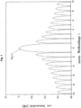
- Fig. 1 shows an example of an ideal transfer function H( ⁇ ) of an AOTF with a rectangular transducer when excited with a single sine.
- the optical transmission properties of the acousto-optical element are adjusted by the crystal cut and the geometry of the transducer mounted on it.
- the choice of geometry can influence both the width of the main lobe and the decay behavior of the side lobes of the transfer function H 0 ( ⁇ ).
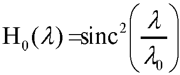
- a rectangular transducer is often implemented, whose normalized transfer function H 0 ( ⁇ ) describes the sinc 2 function.
- H 0 ⁇ sinc 2 ⁇ ⁇ 0
- the frequency f n of the exciting RF signal is determined for a given laser wavelength ⁇ n by, among other factors, the material properties and the geometry of the crystal. It is inversely proportional to the laser wavelength ⁇ n , which can be influenced by the excited diffraction grating. ⁇ n ⁇ 1 f n
- the RF signal used to control the acousto-optical element contains a sinusoidal carrier for each laser line.
- Each sinusoidal carrier of frequency f 1 , f 2 , ... f n excites a diffraction grating for the corresponding laser line in the acousto-optical element.
- the properties of the transfer function can also be characterized as a function of the frequency of the exciting RF signal.
- a ⁇ f BN can be specified to describe the width of the main lobe as a function of the detuning of the tuning frequency of the drive signal. The following applies: ⁇ f B N ⁇ 1 / B N
- B N 2.
- the distance ⁇ between two adjacent laser lines is chosen to be at least large enough so that the main lobes of the transfer function H 0 ( ⁇ ) of the acousto-optical element do not overlap. This is the case if the distance ⁇ between two laser lines is not smaller than the zero distance B N of the main lobe of the transfer function H 0 ( ⁇ ) of the acousto-optical element.
- Adjusting the transducer geometry to tune the transmission characteristics is typically accompanied by a significant increase in the required power of the AOTF's high-frequency drive signal to achieve the required diffraction efficiency of >90%.
- an increase in the RF drive power of up to 7 dB may be required, depending on the wavelength of the laser light.
- Typical values are >+27 dBm ( ⁇ 500 mW) for the modified AOTF compared to +20 dBm ( ⁇ 100 mW) for a standard AOTF.
- Increasing the RF control power causes additional heating of the acousto-optical element and thus causes a change in its optical properties due to the dependence of the speed of sound on the temperature in the crystal (e.g. TeO2).
- thermostabilization with a Peltier element or to implement temperature-controlled frequency tracking of the RF control signal, as for example in DE202007015506 U1 and in DE19827140 A1 described.
- the invention is characterized by the respective characterizing features in a device or a method according to the preambles of the independent claims.
- the acousto-optical element is controlled by two or more sinusoidal RF signals per laser line.
- the spectral spacing ⁇ f of the sinusoidal RF signals is deliberately chosen to result in a superposition of the main lobes of the excited transfer functions H 0 ( ⁇ ).
- the overlap of the main lobes of the excited transfer functions H N ( ⁇ ) is intentional, as this leads to a broadening of the main lobe in the resulting transfer function H ⁇ ( ⁇ ) due to the superposition of the individual transfer functions.
- AO Tunable Filter AOTF.nc-VIS from AA Opto-Electronic (data sheet values): • Optical Wavelength ⁇ 450 - 700 nm • Spectral Resolution (FWHM) 1.5 nm • Drive Frequency f 153 - 80 MHz • Tuning slope k Tune 0.292 MHz / nm
- This data sheet specifies a value of 30kHz/°C for the drift of the AOTF frequency as a function of temperature.
- the signal I has a (nearly) constant envelope.
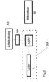
- FIG. 2 A light source is shown schematically, exemplified by a laser L.
- Light source L and AOTF can also be arranged in an illumination module BM (shown in dashed lines), which is optically connected to the microscopic beam path by direct coupling or by one or more optical fibers.
- illumination module BM shown in dashed lines
- a control unit AS which serves to control the AOTF.
- a multi-frequency mixer unit MIX is advantageously provided as a frequency generator between the control unit and the AOTF, the mode of operation of which will be explained in more detail below:
- the invention relates to the control of an acousto-optical element (AOTF/AOM) with a high-frequency signal.
- AOTF/AOM acousto-optical element
- Such a signal contains several high-frequency carriers that are not necessarily evenly spaced ⁇ f from each other and have identical or different signal amplitudes.
- the resulting transfer function H N ( ⁇ ) results from the superposition of the spectrally shifted transfer function H 0 ( ⁇ ) of the individual carriers exciting the acousto-optical element.
- the transfer function H N ( ⁇ ) of the acousto-optical element undergoes a spectral spread, which in particular results in a broadening of its main lobe.
- the decay behavior of the side lobes, which in rectangular transducers is determined by the sinc 2 function, however, does not change or does not change significantly.
- AOTF/AOM acousto-optical element
- the temperature range should include ambient temperatures between 15 °C and 35 °C, whereby the operating temperature of the crystal can be about 20 °C higher than the ambient temperature.
- the inventive solution for controlling acousto-optic elements makes it possible to adapt the spectral properties of the crystal to the spectral properties of the coupled laser light without adapting the transducer geometry, i.e., using standard components.
- An additional positive effect is that the Heating the crystals is no longer necessary. This reduces the adverse heat input into the system. Eliminating the heating and the associated electronic and mechanical components enables the design of more compact assemblies, allowing for a higher degree of system integration. Furthermore, adverse effects from local heating of the crystals are eliminated, as the resulting drift in the transfer function is also compensated for by the widening of its main lobe.
- Another advantage is the almost rectangular characteristic of the main lobe of the transfer function H N ( ⁇ ), which ensures that the angle and intensity of the laser light in the first diffraction order of the AOTF remains stable over the entire specified temperature range of e.g. 15°C to 45°C.
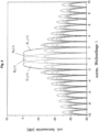
- the transfer function H N ( ⁇ ) at room temperature (2) is spectrally shifted (3) by heating the crystal; the width of its main lobe and the decay behavior of the side lobes are not affected.
- the main lobe of the transfer function is spectrally spread by superimposing several individual main lobes such that the laser line (1) with a fixed wavelength is transmitted unadulterated over the entire temperature range.
- Fig. 4 and 5 The aim is to further clarify the formation of the sum transfer function when controlling an AOTF with an OFDM signal (Orthogonal Frequency-Division Multiplexing).
- the high-frequency signal is preferably generated using an I/Q mixer, which can be either analog or digital.
- the complex baseband signals for driving the in-phase and quadrature paths of the I/Q mixer can be advantageously calculated using the inverse discrete Fourier transform (IDFT) when the signal carrier spacing is equidistant.
- IDFT inverse discrete Fourier transform
- the I/Q mixer also has the advantageous property of suppressing the sidebands of the adjusted main signal so that an optimal main lobe of a signal can be generated.
- a measured distribution of the temperature-dependent frequency drift of the AOTF can advantageously be used, whereby, for example, a monitor diode is advantageously arranged in the beam path, which detects the change in intensity of the signal transmission of the AOTF as a function of the ambient temperature.
- control of the described signal generator for generating the signal can then advantageously be carried out in such a way that the resulting broadened transfer function has essentially the same spectral characteristics for a desired temperature range.
- an optimization process can also advantageously be carried out with the signal generator in order to generate an optimal number and distribution of the spectrally shifted transfer functions depending on the specified temperature difference in which the AOTF has the same transfer characteristic.
- the high-frequency signals for controlling the signal generator such as the I/Q mixer can advantageously be generated using a freely programmable component such as an FPGA.
- the high-frequency signals for controlling the signal generator such as the I/Q mixer can advantageously be generated using a freely programmable component such as an FPGA.
- FPGAs have already been described in a completely different context in connection with laser scanning microscopes: DE102006034905 A1 , DE19858456 A1 .
- the invention solves the complex attempts described in the above-mentioned prior art to solve the problem of temperature dependence of acousto-optical components in an unexpectedly simple yet highly flexible manner.
- the invention is applicable to acousto-optical components in microscopes that influence both the illumination and detection beam paths, for example, to adjust the bandwidth of transmitted or blocked wavelength ranges, even in the case of a broadband light source ("white light laser").
Landscapes
- Physics & Mathematics (AREA)
- General Physics & Mathematics (AREA)
- Nonlinear Science (AREA)
- Optics & Photonics (AREA)
- Spectroscopy & Molecular Physics (AREA)
- Chemical & Material Sciences (AREA)
- Analytical Chemistry (AREA)
- Optical Modulation, Optical Deflection, Nonlinear Optics, Optical Demodulation, Optical Logic Elements (AREA)
- Microscoopes, Condenser (AREA)
Description
- Ein - Lasersystem in einem Laser- Scanning-Mikroskop, wie unter anderem in
EP 1 795 938 A2 ,DE 19702753C2 beschrieben, weist zur Wellenlängenauswahl und zur Beeinflussung der Intensität des Laserlichts ein akusto-optisches Element (AOTF/AOM) auf, dessen spektrale Eigenschaften an die spektrale Charakteristik des zu übertragenden Laserlichts angepasst sind. -
Abb. 1 zeigt beispielhaft eine ideale Übertragungsfunktion H(λ) eines AOTF mit rechteckförmigem Transducer bei Anregung mit einem Einzelsinus. - Üblicherweise werden durch den Schnitt des Kristalls und die Geometrie des darauf angebrachten Transducers die optischen Übertragungseigenschaften des akustooptischen Elements (AOTF/AOM) eingestellt. Durch die Wahl der Geometrie können hierbei sowohl die Breite der Hauptkeule als auch das Abklingverhalten der Nebenkeulen der Übertragungsfunktion H0(λ) beeinflusst werden. Häufig wird ein rechteckförmiger Transducer realisiert, dessen normierte Übertragungsfunktion H0(λ) die sinc2-Funktion beschreibt.
- Die Frequenz fn des anregenden HF-Signals ist für eine vorgegebene Laserwellenlänge λn unter anderem durch die Materialeigenschaften und die Geometrie des Kristalls bestimmt. Sie ist umgekehrt proportional zu der Laserwellenlänge λn, die sich durch das angeregte Beugungsgitter beeinflussen lässt.

- Die Übertragungsfunktion H0(λ) wird unter anderem durch die folgenden Parameter charakterisiert:
- B3dB - Bandbreite, bei der die Hauptkeule der Übertragungsfunktion auf die Hälfte ihres Maximums abgeklungen ist (auch FWHM - full width at half maximum)
- BN - Abstand der Nullstellen, die die Hauptkeule der Übertragungsfunktion begrenzen
- Für die gleichzeitige Beeinflussung von zwei oder mehr Laserlinien (λ1, λ2, ... λn) enthält das zur Ansteuerung des akusto-optischen Elements verwendete HF-Signal pro Laserlinie einen sinus-förmigen Träger. Jeder sinusförmige Träger der Frequenz f1, f2, ... fn regt im akusto-optischen Element ein Beugungsgitter für die entsprechende Laserlinie an.
- Auf Grund der Beziehung λn ~ 1/fn können die Eigenschaften der Übertragungsfunktion auch in Abhängigkeit von der Frequenz des anregenden HF-Signals charakterisiert werden. Man kann insbesondere ein ΔfBN zur Beschreibung der Breite der Hauptkeule in Abhängigkeit von der Verstimmung der Abstimmfrequenz des Ansteuersignals angeben. Es gilt:

- Für den rechteckförmigen Transducer gilt B3dB = 0,89 und BN = 2. Die Größen BN und B3dB verhalten sich demnach zueinander wie folgt:

- Der Abstand Δλ zweier benachbarter Laserlinien wird mindestens so groß gewählt, dass sich die Hauptkeulen der Übertragungsfunktion H0(λ) des akusto-optischen Elements nicht überlagern. Dies ist gegeben, wenn der Abstand Δλ zweier Laserlinien nicht kleiner als der Nullstellenabstand BN der Hauptkeule der Übertragungsfunktion H0(λ) des akusto-optischen Elements ist. Es gilt:

- Für den rechteckförmigen Transducer ergibt sich somit:

- Die Anpassung der Transducer-Geometrie zur Einstellung der Übertragungseigenschaften geht üblicherweise einher mit einer signifikanten Erhöhung der notwendigen Leistung des hochfrequenten Ansteuersignals des AOTF, um die geforderte Beugungseffizienz von >90% zu erreichen. Im Vergleich zu einem Standard-AOTF mit rechteckförmigen Transducer kann eine Anhebung der HF-Ansteuerleistung je nach Wellenlänge des Laserlichts um bis zu 7dB erforderlich sein. Typische Werte liegen bei >+27dBm (~500mW) für den modifizierten AOTF im Gegensatz zu +20dBm (~100mW) für einen Standard-AOTF.
- Die Anhebung der HF-Steuerleistung verursacht eine zusätzliche Erwärmung des akusto-optischen Elements und bewirkt dadurch auf Grund der Abhängigkeit der Schallgeschwindigkeit von der Temperatur im Kristall (z.B. TeO2) eine Änderung seiner optischen Eigenschaften.
- Durch die Erwärmung erfährt insbesondere die Übertragungsfunktion H0(λ) eine deutliche spektrale Verschiebung.
- Durch das Aufheizen des AOTF-Kristalls auf eine Temperatur deutlich oberhalb der Raumtemperatur (z.B. 50°C) mit einer geregelten elektrischen Heizung kann dieser unerwünschten Temperaturdrift entgegengewirkt werden (
DE-19827140-A1 ). - Alternativ ist es möglich, die Temperaturstabilisierung mit einem Peltierelement vorzunehmen oder eine temperaturgesteuerte Frequenznachführung des HF-Ansteuersignals zu realisieren, wie zum Beispiel in
DE202007015506 U1 und inDE19827140 A1 beschrieben. - Lokale Veränderungen der Kristalltemperatur durch kurzzeitige Variation der HF-Ansteuerleistung - zum Beispiel auf Grund von Intensitätsmodulation des Laserlichts während der Bildaufnahme - können durch derartige Verfahren nicht erfasst und kompensiert werden und haben, bezogen auf die erste Beugungsordnung des AOTF, unerwünschte Veränderungen von Winkel und Intensität des Laserlichts durch die spektrale Verschiebung der Übertragungsfunktion H0(λ) zur Folge.
- Auftretende Interferenzen bei der Nutzung multipler Wellenlängen sind durch Tian & Herrmann beschrieben (Journal of Lightwave Technology 13: 1146 - 1154; 1995). Die Einstellung eines Bandpasses eines AOTF durch Anregung mit mehreren Frequenzen ist auch aus
US3729251 bekannt. Ferner offenbartDE102006053187 A1 ein Mikroskop mit einem AOTF, dessen Bandpass einstellbar ist. - Die Erfindung wird bei einer Vorrichtung bzw. einem Verfahren gemäß den Oberbegriffen der unabhängigen Ansprüche durch die jeweiligen kennzeichnenden Merkmale charakterisiert.
- Die durch eine Vorrichtung nach Anspruch 1 bzw. ein Verfahren nach Anspruch 5 definierte Erfindung und ihre Wirkungen und Vorteile werden nachstehend näher erläutert.
- Das akusto-optische Element wird erfindungsgemäß durch zwei oder mehr sinusförmige HF-Signale pro Laserlinie angesteuert. Der spektrale Abstand Δf der sinusförmigen HF-Signale wird bewusst so gewählt, dass es zu einer Überlagerung der Hauptkeulen der angeregten Übertragungsfunktionen H0(λ) kommt. Die Überlappung der Hauptkeulen der angeregten Übertragungsfunktionen HN(λ) ist gewollt, da dies durch die Superposition der Einzelübertragungsfunktionen zu einer Verbreiterung der Hauptkeule in der resultierenden Übertragungsfunktion HΣ(λ) führt.
- AO Tunable Filter AOTF. nc-VIS von AA Opto-Electronic (Datenblattwerte):
• Optical Wavelength λ 450 - 700 nm • Spectral Resolution (FWHM) 1,5 nm • Drive Frequency f 153 - 80 MHz • Abstimmsteilheit kTune 0,292 MHz / nm - Daraus lassen sich mit den oben angegebenen Beziehungen unter Annahme eines rechteckförmigen Transducers die folgenden Werte berechnen:
• Abstand der Nullstellen BN 3,37 nm (BN = FWHM / 0,445) • Abstand der Nullstellen ΔfBN0,98 MHz (ΔfBN = kTune · BN) • Mindestabstand der Laserlinien Δλ ≥ 3,37 nm (Δλ ≥ 2,247 · FWHM) • Abstand der sinusförmigen Träger Δf bei Nutzung im Sinne der Erfindung: ≥ 0,98 MHz • Abstand der sinusförmigen Träger Δf < 0,98 MHz - In diesem Datenblatt ist ein Wert von 30kHz/°C für die Drift der AOTF Frequenz in Abhängigkeit von der Temperatur angegeben.
- Durch eine geschickte Wahl der Anfangsphasenlage und Amplitude der einzelnen Träger des erzeugten Signals kann man erreichen, dass das Signal I eine (nahezu) konstante Hüllkurve aufweist.
- Die Erfindung wird nachstehend anhand der schematischen Zeichnungen in
Fig. 2-5 näher erläutert. - In
Fig. 2 ist schematisch eine Lichtquelle dargestellt, beispielhaft durch einen Laser L. - Die Lichtquelle kann auch aus mehreren über Strahlteiler zusammengeführten Lasern, wie im Stand der Technik dargestellt, bestehen. Das Licht der Lichtquelle L gelangt über einen AOTF zur Wellenlängenauswahl und Intensitätssteuerung in Richtung eines Mikroskops, vorzugsweise eines Laser - Scanning- Mikroskops.
- Lichtquelle L und AOTF können auch in einem (gestrichelt dargestellten) Beleuchtungsmodul BM angeordnet sein, das durch Direktkopplung oder durch eine oder mehrere Lichtleitfasern mit dem mikroskopischen Strahlengang optisch verbunden ist.
- Eine Ansteuereinheit AS, meist verbunden mit weiteren Mikroskopfunktionen, dient auch der Ansteuerung des AOTF.
- Zwischen der Ansteuereinheit und dem AOTF ist vorteilhaft gemäß der Erfindung als Frequenzgenerator eine Mehrfrequenz- Mischereinheit MIX vorgesehen, deren Wirkungsweise im Weiteren noch näher erläutert wird:
Die Erfindung betrifft die Ansteuerung eines akusto-optischen Elements (AOTF/AOM) mit einem Hochfrequenzsignal. Ein derartiges Signal enthält mehrere hochfrequente Träger, die - nicht zwingend - einen gleichmäßigen Abstand Δf zueinander haben und identische oder unterschiedliche Signalamplituden aufweisen. - Diese Art der Ansteuerung bewirkt, dass mehrere durch die Kristall- und Transducer-Geometrie vorgegebene Übertragungsfunktion H0(λ) überlagert werden, welche um ein Vielfaches von Δf zueinander verschoben sind und durch die Amplitude des jeweils anregenden Einzelträgers bewertet werden.
- Die resultierende Übertragungsfunktion HN(λ) ergibt sich aus der Superposition der spektral verschobenen Übertragungsfunktion H0(λ) der das akusto-optische Element anregenden Einzelträger.
- Bezüglich des Abklingverhaltens der Nebenkeulen der Übertragungsfunktion ist es sinnvoll, den Trägerabstand Δf des ansteuernden Signals so zu wählen, dass die Hauptkeulen benachbarter Übertragungsfunktionen die Minima der jeweils direkten Nachbarn ergänzen.
- Die Übertragungsfunktion HN(λ) des akusto-optischen Elements erfährt durch diese Ansteuerung und der daraus resultierenden Superposition mehrerer Übertragungsfunktionen H0(λ) eine spektrale Spreizung, welche insbesondere eine Aufweitung ihrer Hauptkeule zur Folge hat. Das Abklingverhalten der Nebenkeulen, welches bei rechteckförmigen Transducern durch die sinc2-Funktion vorgegeben ist, verändert sich hingegen nicht oder nicht signifikant.
- Die erfindungsgemässe Anregung eines akusto-optischen Elements (AOTF/AOM) erlaubt es demnach, die spektrale Breite der Hauptkeule der Übertragungsfunktion beliebig zu vergrößern, ohne das Abklingverhalten der Nebenkeulen wesentlich zu verändern. Dies ermöglicht, die Hauptkeule der Übertragungsfunktion so aufzuspreizen, dass sowohl der Puls eines Lasersystems wie in u.a.
EP 1 795 938 A2 beschrieben optimal übertragen wird, als auch der Temperaturgang des Kristalls keinen Einfluss mehr auf die Übertragung von Laserlicht einer bestimmten Wellenlänge hat. Dies gelingt dadurch, dass die Breite der Hauptkeule durch die Anzahl der Träger des Hochfrequenzsignales und ihre Abstände untereinander so weit aufgespreizt wird, dass der zu übertragende Puls mit seiner spektralen Breite oder auch die zu übertragende Wellenlänge eines Gas- oder DPSS Lasersystems auch bei maximaler Temperaturdrift des Kristalls noch innerhalb der Hauptkeule der Übertragungsfunktion liegt. Der Temperaturbereich sollte dabei Umgebungstemperaturen im Bereich zwischen 15 °C und 35 °C umfassen, wobei Arbeitstemperatur des Kristalls um etwa 20 °C höher als die Umgebungstemperatur liegen kann. - Durch die erfindungsgemässe Lösung zur Ansteuerung akusto-optischer Elemente (AOTF/AOM) wird es möglich, ohne Anpassung der Transducer-Geometrie, das heisst unter Verwendung von Standard-Bauteilen, die spektralen Eigenschaften des Kristalls an die spektralen Eigenschaften des eingekoppelten Laserlichts anzupassen. Ein zusätzlicher positiver Effekt besteht darin, dass vollständig auf die Heizung der Kristalle verzichtet werden kann. Dies verringert den nachteiligen Eintrag von Wärme im System. Durch den Wegfall der Heizung und der dafür notwendigen elektronischen und mechanischen Bauelemente wird der Entwurf kompakterer Baugruppen möglich, die ein höheres Maß an Systemintegration erlauben. Des Weiteren treten auch keine nachteiligen Effekte durch lokale Erwärmungen der Kristalle mehr auf, da die dadurch verursachte Drift der Übertragungsfunktion ebenfalls durch die Aufweitung ihrer Hauptkeule aufgefangen wird.
- Vorteilhaft ist zudem die nahezu rechteckförmige Charakteristik der Hauptkeule der Übertragungsfunktion HN(λ), welche sicherstellt, dass Winkel und Intensität des Laserlichts in der ersten Beugungsordnung des AOTF über den gesamten spezifizierten Temperaturbereich von z.B. 15°C bis 45°C stabil bleibt.
- Das Prinzip der Kompensation der Temperaturdrift bei Ansteuerung des akustooptischen Elements mit einem hochfrequenten Signal verdeutlicht
Abbildung 3 . - Sie zeigt das erfindungsgemässe Prinzip der Kompensation der Temperaturdrift eines AOTF/AOM durch Ansteuerung des Kristalls mit fünf Trägern im Wesentlichen gleicher Leistung.
- Die Übertragungsfunktion HN(λ) bei Raumtemperatur (2) wird durch Erwärmung des Kristalls spektral verschoben (3); die Breite ihrer Hauptkeule und das Abklingverhalten der Nebenkeulen werden dadurch nicht beeinflusst. Durch eine geeignete Wahl von Trägeranzahl und -abstand wird die Hauptkeule der Übertragungsfunktion durch Überlagerung mehrerer einzelner Hauptkeulen spektral so aufgespreizt, dass die Laserlinie (1) mit einer festen Wellenlänge über den gesamten Temperaturbereich unverfälscht übertragen wird.
- In
Abb. 4 und5 soll die Entstehung der Summen-Übertragungsfunktion bei Ansteuerung eines AOTF mit einem OFDM-Signal (Orthogonal Frequency-Division Multiplexing, deutsch Orthogonales Frequenzmultiplexverfahren) weiter verdeutlicht werden. - In beiden Abbildungen wird ein OFDM-Signal mit drei Trägern verwendet - die resultierende Übertragungsfunktion HN(λ) ergibt sich also aus der Superposition von jeweils drei spektral um λ bzw. 0,7 n λ gegeneinander verschobenen Kurven Ho(λ), H+1(λ) H-1(λ) in
Fig.4 und Ho(λ) H+0,7(λ) H -0,7(λ). - Die Abbildungen unterscheiden sich in der Größe der spektralen Verschiebung. In der Zeichnung
Abb.4 die Verschiebung so gewählt, daß die Hauptkeule einer Übertragungsfunktion jeweils in ein Minimum der benachbarten Funktion fällt. In der Zeichnung 5 ist die Verschiebung etwas geringer (0,7 statt 1). - Die Erzeugung des hochfrequenten Signals erfolgt vorzugsweise mit einem I/Q-Mischer, welcher sowohl analog als auch digital ausgeführt sein kann. Die komplexen Basisbandsignale zur Ansteuerung des Inphase- und Quadraturpfads des I/Q-Mischers lassen sich bei äquidistanten Trägerabständen des Signals vorteilhaft mit Hilfe der inversen diskreten Fouriertransformation (IDFT) berechnen.
- Der I/Q-Mischer außerdem hat die vorteilhafte Eigenschaft, die Seitenbänder des eingestellten Hauptsignals zu unterdrücken, so dass eine optimale Hauptkeule eines Signals erzeugt werden kann.
- Zur Einstellung des Frequenzgenerators wie des I/Q Mischers kann vorteilhaft eine gemessene Verteilung der temperaturabhängigen Frequenzdrift des AOTF herangezogen werden, wobei vorteilhaft beispielsweise eine Monitordiode im Strahlengang angeordnet ist, die die Intensitätsveränderung der Signalübertragung des AOTF in Anhängigkeit von der Umgebungstemperatur erfasst.
- Die Ansteuerung des beschriebenen Signalgenerators zur Erzeugung des Signales kann dann vorteilhaft derart erfolgen, dass die entstandene verbreiterte Übertragungsfunktion für einen gewünschten Temperaturbereich im Wesentlichen eine gleiche spektrale Charakteristik aufweist.
- Zu diesem Zweck kann auch vorteilhaft mit dem Signalgenerator ein Optimierungsverfahren erfolgen, um in Abhängigkeit von der vorgegebenen Temperaturdifferenz, in der der AOTF gleiche Übertragungscharakteristik aufweist eine optimale Anzahl und Verteilung der spektral versetzten Übertragungsfunktionen zu erzeugen.
- Die Hochfrequenzsignale zur Ansteuerung des Signalgenerators wie des I/Q-Mischers können vorteilhaft mit einem frei programmierbaren Bauteil wie einem FPGA erzeugt werden.
- Die Hochfrequenzsignale zur Ansteuerung des Signalgenerators wie des I/Q- Mischers können vorteilhaft mit einem frei programmierbaren Bauteil wie einem FPGA erzeugt werden.
- FPGA sind in einem völlig anderen Zusammenhang bereits im Zusammenhang mit Laser-Scanning- Mikroskopen beschrieben worden:
DE102006034905 A1 ,DE19858456 A1 . - Durch die Erfindung werden in unerwartet einfacher und dennoch sehr variabler Weise die im obengenannten Stand der Technik beschriebenen aufwändigen Versuche, das Problem der Temeraturabhängigkeit akustooptischer Bauteile zu beheben, gelöst. Die Erfindung ist auf akustooptische Bauteile in Mikroskopen anwendbar, die sowohl auf den Beleuchtungs- als auch auf den Detektionsstrahlengang Einfluss nehmen, beispielsweise zur Einstellung der Bandbreite durchgelassener oder gesperrter Wellenlängenbereiche, auch z.B. bei einer breitbandigen Lichtquelle ("Weisslichtlaser").
Claims (10)
- Vorrichtung zur Ansteuerung eines akustooptischen Bauteils für ein Mikroskop,wobei das akustooptische Bauteil zum Beeinflussen des als Beleuchtungs- und/oder Detektionslicht eines Mikroskops in Form eines Pulses eines Lasersystems mit einer spektralen Breite oder einer Laserlinie (1) einer bestimmten Wellenlänge hindurchtretenden Laserlichtes eingerichtet ist,umfassend- das akustooptische Bauteil, wobei das akustooptische Bauteil eine Ubertragungsfunktion (H0(λ)) aufweist, durch die eine Beziehung zwischen den spektralen Eigenschaften des akustooptischen Bauteils und einer spektralen Charakteristik des zu übertragenden Laserlichts beschrieben ist,- und mindestens einen Frequenzgenerator zur Einstellung einer Beleuchtungswellenlänge des Beleuchtungslichts und/oder einer Detektionswellenlänge des Detektionslichts, wobei der Frequenzgenerator zur Steuerung der Beeinflussung mit dem akustooptischen Bauteil verbunden ist,dadurch gekennzeichnet dass, der Frequenzgenerator derart ausgebildet ist, dass er ein Signal erzeugt, durch das durch Überlagerung mehrerer einzelner Hauptkeulen von Übertragungsfunktionen eine resultierende Hauptkeule einer resultierenden Übertragungsfunktion spektral so aufgespreizt ist, dass der Puls mit seiner spektralen Breite oder die Laserlinie (1) mit einer festen Wellenlänge auch bei maximaler Temperaturdrift des AOTF-Kristalls noch innerhalb der Hauptkeule der Übertragungsfunktion liegt,wobei die Ansteuerung des akustooptischen Bauteils durch zwei oder mehrere Ansteuersignale derart erfolgt, dass zwei oder mehr sich überlappende und/oder überlagernde Hauptkeulen der Übertragungsfunktion des akustooptischen Bauteils oder Hauptmaxima erzeugt werden.
- Vorrichtung nach Anspruch 1,
wobei das akustooptische Bauteil ein AOTF oder ein AOM ist. - Vorrichtung nach einem der vorangehenden Ansprüche 1 oder 2
wobei der Frequenzgenerator ein I/Q Mischer ist. - Verfahren zur Ansteuerung eines akustooptischen Bauteils für ein Mikroskop,wobei das akustooptische Bauteil das als Beleuchtungs- und/oder Detektionslicht eines Mikroskops in Form eines Pulses eines Lasersystems mit einer spektralen Breite oder einer Laserlinie (1) einer bestimmten Wellenlänge hindurchtretende Laserlicht beeinflusst,wobei eine Einstellung der Beleuchtungs und/oder Detektionswellenlänge mit mindestens einem Frequenzgenerator erfolgt, der mit dem akustooptischen Bauteil verbunden ist und die Beeinflussung steuert,dadurch gekennzeichnet dass, mittels des Frequenzgenerators ein Signal erzeugt wird, das durch Überlagerung mehrerer einzelner Hauptkeulen von Übertragungsfunktionen eine resultierende Hauptkeule einer resultierenden Übertragungsfunktion spektral so aufspreizt, dass temperaturabhängige Verschiebungen der Übertragungsfunktion das Übertragungsverhalten des Kristalls des akustooptischen Bauteils nicht verändern und der Puls mit seiner spektralen Breite oder die Laserlinie (1) mit einer festen Wellenlänge auch bei maximaler Temperaturdrift des AOTF-Kristalls noch innerhalb der Hauptkeule der Übertragungsfunktion liegt,wobei die Ansteuerung des akustooptischen Bauteils durch zwei oder mehrere Ansteuersignale derart erfolgt, dass zwei oder mehr sich überlappende und/oder überlagernde Hauptkeulen der Übertragungsfunktion des akustooptischen Bauteils oder Hauptmaxima erzeugt werden.
- Verfahren nach Anspruch 4,
wobei die Hauptkeulen jeweils durch zwei Minima begrenzt sind. - Verfahren nach einem der Ansprüche 4 oder 5,
wobei das Verhältnis der Intensität Hauptkeule/ Nebenkeule mindestens 10:1 beträgt. - Verfahren nach einem der Ansprüche 4-6,
wobei beidseitig der Beleuchtungs- und / oder Detektionswellenlänge spektral verschobene Übertragungsfrequenzen vorgesehen sind. - Verfahren nach einem der Ansprüche 4-7,
wobei die die Einstellung der Signalverteilung des Frequenzgenerators anhand einer gemessenen Temperaturdriftkurve des akustooptischen Bauteils erfolgt. - Verfahren nach einem der Ansprüche 4-8,
wobei in einem Optimierungsverfahren die Signalverteilung verändert wird und die entstandene Verteilung bezüglich ihres Temperaturverhaltens erfasst und korrigiert wird. - Mikroskop, beinhaltend eine Vorrichtung nach einem der Ansprüche 1-3.
Applications Claiming Priority (2)
| Application Number | Priority Date | Filing Date | Title |
|---|---|---|---|
| DE102014009142.2A DE102014009142A1 (de) | 2014-06-20 | 2014-06-20 | Verfahren und Vorrichtung zur Ansteuerung eines akustooptischen Bauteils |
| PCT/EP2015/001240 WO2015192967A1 (de) | 2014-06-20 | 2015-06-19 | Verfahren und vorrichtung zur ansteuerung eines akustooptischen bauteils |
Publications (2)
| Publication Number | Publication Date |
|---|---|
| EP3158384A1 EP3158384A1 (de) | 2017-04-26 |
| EP3158384B1 true EP3158384B1 (de) | 2025-04-09 |
Family
ID=53483766
Family Applications (1)
| Application Number | Title | Priority Date | Filing Date |
|---|---|---|---|
| EP15730966.7A Active EP3158384B1 (de) | 2014-06-20 | 2015-06-19 | Verfahren und vorrichtung zur ansteuerung eines akustooptischen bauteils |
Country Status (6)
| Country | Link |
|---|---|
| US (1) | US10302490B2 (de) |
| EP (1) | EP3158384B1 (de) |
| JP (1) | JP6514723B2 (de) |
| CN (1) | CN106574867B (de) |
| DE (1) | DE102014009142A1 (de) |
| WO (1) | WO2015192967A1 (de) |
Families Citing this family (4)
| Publication number | Priority date | Publication date | Assignee | Title |
|---|---|---|---|---|
| LU93098B1 (de) * | 2016-06-03 | 2018-01-22 | Leica Microsystems | Verfahren zum Einstellen der Intensität eines Lichtstrahls in einer optischen Anordnung und zugehörige optische Anordnung |
| EP3538941B1 (de) | 2016-11-10 | 2025-04-23 | The Trustees of Columbia University in the City of New York | Schnelles hochauflösendes bildgebungsverfahren für grosse proben |
| US12468186B2 (en) | 2017-04-25 | 2025-11-11 | Leica Microsystems Cms Gmbh | Method and signal generator for controlling an acousto-optic element |
| CN107219241B (zh) | 2017-05-05 | 2020-10-16 | 中国科学院上海光学精密机械研究所 | 原位时间分辨x射线吸收谱的测量装置和测量方法 |
Family Cites Families (19)
| Publication number | Priority date | Publication date | Assignee | Title |
|---|---|---|---|---|
| US3729251A (en) | 1971-06-16 | 1973-04-24 | Hewlett Packard Co | Acousto-optic filter having electrically variable resolution |
| DE19702753C2 (de) | 1997-01-27 | 2003-04-10 | Zeiss Carl Jena Gmbh | Laser-Scanning-Mikroskop |
| DE19827140C2 (de) | 1998-06-18 | 2002-12-12 | Zeiss Carl Jena Gmbh | Laserscanmikroskop mit AOTF |
| DE19858456A1 (de) | 1998-12-18 | 2000-07-06 | Leica Microsystems | Verfahren zum Auffinden, zur Aufnahme und gegebenenfalls zur Auswertung von Objektstrukturen |
| DE10029167B8 (de) | 2000-06-19 | 2015-07-02 | Leica Microsystems Cms Gmbh | Verfahren und Vorrichtung zur Temperaturstabilisierung optischer Bauteile |
| DE10137158B4 (de) * | 2001-07-30 | 2005-08-04 | Leica Microsystems Heidelberg Gmbh | Verfahren zur Scanmikroskopie und Scanmikroskop |
| JP4331454B2 (ja) * | 2001-10-03 | 2009-09-16 | オリンパス株式会社 | 走査型レーザ顕微鏡 |
| CN100541270C (zh) | 2004-01-20 | 2009-09-16 | 讯宝科技公司 | 用于调制激光的声光调制器的电调整 |
| JP2005274155A (ja) | 2004-03-22 | 2005-10-06 | Olympus Corp | 欠陥検査装置 |
| DE102005059338A1 (de) | 2005-12-08 | 2007-06-14 | Carl Zeiss Jena Gmbh | Verfahren und Anordnung zur Untersuchung von Proben |
| DE102006034905B4 (de) | 2006-07-28 | 2015-07-30 | Carl Zeiss Microscopy Gmbh | Anordnung zur Signalverarbeitung am Ausgang eines Mehrkanaldetektors |
| DE102006053187A1 (de) | 2006-11-09 | 2008-05-15 | Leica Microsystems Cms Gmbh | Akustooptisches Bauteil |
| DE102007024075B4 (de) * | 2007-05-22 | 2022-06-09 | Leica Microsystems Cms Gmbh | Durchstimmbares akusto-optisches Filterelement, einstellbare Lichtquelle, Mikroskop und akusto-optischer Strahlteiler |
| DE102007053199B4 (de) | 2007-11-06 | 2026-05-07 | Leica Microsystems Cms Gmbh | Vorrichtung und Verfahren zur Ansteuerung eines akustooptischen Bauteils |
| DE202007015506U1 (de) | 2007-11-06 | 2008-02-21 | Leica Microsystems Cms Gmbh | Vorrichtung zur Ansteuerung eines akustooptischen Bauteils |
| CN201681208U (zh) | 2009-12-10 | 2010-12-22 | 中国科学院西安光学精密机械研究所 | 一种具有图像漂移补偿的aotf光学系统 |
| WO2012024347A1 (en) * | 2010-08-16 | 2012-02-23 | The University Of Chicago | Real-time mapping of electronic structure with single-shot two-dimensional electronic spectroscopy |
| EP2950711A4 (de) * | 2013-01-31 | 2016-09-21 | Univ Ramot | Nachweis, diagnose und überwachung von osteoporose durch ein fotoakustisches verfahren |
| DE102013227103B4 (de) * | 2013-09-03 | 2018-05-30 | Leica Microsystems Cms Gmbh | Mikroskop mit einer akustooptischen Vorrichtung |
-
2014
- 2014-06-20 DE DE102014009142.2A patent/DE102014009142A1/de active Pending
-
2015
- 2015-06-19 WO PCT/EP2015/001240 patent/WO2015192967A1/de not_active Ceased
- 2015-06-19 US US15/320,567 patent/US10302490B2/en active Active
- 2015-06-19 EP EP15730966.7A patent/EP3158384B1/de active Active
- 2015-06-19 CN CN201580040299.6A patent/CN106574867B/zh active Active
- 2015-06-19 JP JP2016574070A patent/JP6514723B2/ja active Active
Also Published As
| Publication number | Publication date |
|---|---|
| US10302490B2 (en) | 2019-05-28 |
| CN106574867A (zh) | 2017-04-19 |
| JP2017524978A (ja) | 2017-08-31 |
| US20180231416A1 (en) | 2018-08-16 |
| JP6514723B2 (ja) | 2019-05-15 |
| WO2015192967A1 (de) | 2015-12-23 |
| EP3158384A1 (de) | 2017-04-26 |
| DE102014009142A1 (de) | 2015-12-24 |
| CN106574867B (zh) | 2018-11-20 |
Similar Documents
| Publication | Publication Date | Title |
|---|---|---|
| EP2364106B1 (de) | Wellenlängenabstimmbare lichtquelle | |
| EP2215517B1 (de) | Vorrichtung und verfahren zur ansteuerung eines akustooptischen bauteils | |
| DE102008059902B3 (de) | Verfahren und Vorrichtung zum Erzeugen eines selbstrefernzierten optischen Frequenzkamms | |
| EP2621031B1 (de) | Optikanordnung und Verfahren zum Erzeugen von Lichtpulsen veränderbarer Verzögerung | |
| EP3120428B1 (de) | Verfahren zum betreiben einer lasereinrichtung, resonatoranordnung und verwendung eines phasenschiebers | |
| DE102006023601B4 (de) | Lasersystem | |
| EP2908168B1 (de) | Erzeugung von Frequenzkämmen und sinc-förmigen Nyquist-Pulsefolgen großer Bandbreite und abstimmbarer Repetitionsrate | |
| EP3227751B1 (de) | Vorrichtung und verfahren zum erzeugen elektromagnetischer strahlung | |
| DE112013003486T5 (de) | Reduzierung der spektralen Bandbreite von Lasern | |
| DE102014009142A1 (de) | Verfahren und Vorrichtung zur Ansteuerung eines akustooptischen Bauteils | |
| DE10029167B4 (de) | Verfahren und Vorrichtung zur Temperaturstabilisierung optischer Bauteile | |
| EP2515395B1 (de) | Verfahren und Vorrichtung zur Verringerung der Bandbreite der stimulierten Brillouin-Streuung | |
| DE102015002559A1 (de) | Stabilisieren optischer Frequenzkämme | |
| DE102012023605B4 (de) | Verfahren und Vorrichtung zur Synthese von elektromagnetischer Strahlung | |
| DE102017131244B3 (de) | Verfahren und Vorrichtung zur Erzeugung stabilisierter, gepulster Laserstrahlung | |
| EP3602189B1 (de) | Verfahren und signalgenerator zum ansteuern eines akustooptischen elements | |
| DE102007032253A1 (de) | Verfahren und Vorrichtung zur Regelung der Lichtleistung eines mittels einer nichtlinear optischen Anordnung gewonnenen, Frequenz-konvertierten Laserstrahls | |
| DE2228617A1 (de) | Verfahren und vorrichtung zum steuern des aufloesungsvermoegens | |
| EP3667390A1 (de) | Verfahren und signalgenerator zum ansteuern eines akustooptischen elements | |
| DE4236016C1 (de) | Anordnung zur Kompensation von Resonanzfrequenzänderungen eines Hohlraumresonators | |
| DE202007015506U1 (de) | Vorrichtung zur Ansteuerung eines akustooptischen Bauteils | |
| DE102016107501B3 (de) | Wellenlängenmessvorrichtung und Verfahren zur Messung der Wellenlänge | |
| DE10203198A1 (de) | Verfahren zur Materialbearbeitung mit Laserimpulsen großer spektraler Bandbreite und Vorrichtung zur Durchführung des Verfahrens | |
| DE19937565A1 (de) | Verfahren zum Regeln der Ausgangsleistung eines Laserstrahls sowie eine dazugehörige Vorrichtung |
Legal Events
| Date | Code | Title | Description |
|---|---|---|---|
| STAA | Information on the status of an ep patent application or granted ep patent |
Free format text: STATUS: THE INTERNATIONAL PUBLICATION HAS BEEN MADE |
|
| PUAI | Public reference made under article 153(3) epc to a published international application that has entered the european phase |
Free format text: ORIGINAL CODE: 0009012 |
|
| STAA | Information on the status of an ep patent application or granted ep patent |
Free format text: STATUS: REQUEST FOR EXAMINATION WAS MADE |
|
| 17P | Request for examination filed |
Effective date: 20170110 |
|
| AK | Designated contracting states |
Kind code of ref document: A1 Designated state(s): AL AT BE BG CH CY CZ DE DK EE ES FI FR GB GR HR HU IE IS IT LI LT LU LV MC MK MT NL NO PL PT RO RS SE SI SK SM TR |
|
| AX | Request for extension of the european patent |
Extension state: BA ME |
|
| RIN1 | Information on inventor provided before grant (corrected) |
Inventor name: ROSCHER, BURKHARD Inventor name: WILHELM, STEFAN Inventor name: MOEHLER, GUNTER |
|
| DAV | Request for validation of the european patent (deleted) | ||
| DAX | Request for extension of the european patent (deleted) | ||
| STAA | Information on the status of an ep patent application or granted ep patent |
Free format text: STATUS: EXAMINATION IS IN PROGRESS |
|
| 17Q | First examination report despatched |
Effective date: 20191216 |
|
| REG | Reference to a national code |
Ref country code: DE Ref legal event code: R079 Free format text: PREVIOUS MAIN CLASS: G02B0021000000 Ipc: G01J0003120000 Ref country code: DE Ref legal event code: R079 Ref document number: 502015017066 Country of ref document: DE Free format text: PREVIOUS MAIN CLASS: G02B0021000000 Ipc: G01J0003120000 |
|
| RIC1 | Information provided on ipc code assigned before grant |
Ipc: G02B 21/00 20060101ALI20241001BHEP Ipc: G02F 1/33 20060101ALI20241001BHEP Ipc: G02B 21/16 20060101ALI20241001BHEP Ipc: G02F 1/11 20060101ALI20241001BHEP Ipc: G01J 3/12 20060101AFI20241001BHEP |
|
| GRAP | Despatch of communication of intention to grant a patent |
Free format text: ORIGINAL CODE: EPIDOSNIGR1 |
|
| STAA | Information on the status of an ep patent application or granted ep patent |
Free format text: STATUS: GRANT OF PATENT IS INTENDED |
|
| INTG | Intention to grant announced |
Effective date: 20241108 |
|
| GRAS | Grant fee paid |
Free format text: ORIGINAL CODE: EPIDOSNIGR3 |
|
| GRAA | (expected) grant |
Free format text: ORIGINAL CODE: 0009210 |
|
| STAA | Information on the status of an ep patent application or granted ep patent |
Free format text: STATUS: THE PATENT HAS BEEN GRANTED |
|
| AK | Designated contracting states |
Kind code of ref document: B1 Designated state(s): AL AT BE BG CH CY CZ DE DK EE ES FI FR GB GR HR HU IE IS IT LI LT LU LV MC MK MT NL NO PL PT RO RS SE SI SK SM TR |
|
| REG | Reference to a national code |
Ref country code: GB Ref legal event code: FG4D Free format text: NOT ENGLISH |
|
| RIN1 | Information on inventor provided before grant (corrected) |
Inventor name: MOEHLER, GUNTER Inventor name: WILHELM, STEFAN Inventor name: ROSCHER, BURKHARD |
|
| REG | Reference to a national code |
Ref country code: CH Ref legal event code: EP |
|
| REG | Reference to a national code |
Ref country code: DE Ref legal event code: R096 Ref document number: 502015017066 Country of ref document: DE |
|
| REG | Reference to a national code |
Ref country code: IE Ref legal event code: FG4D Free format text: LANGUAGE OF EP DOCUMENT: GERMAN |
|
| REG | Reference to a national code |
Ref country code: NL Ref legal event code: MP Effective date: 20250409 |
|
| PG25 | Lapsed in a contracting state [announced via postgrant information from national office to epo] |
Ref country code: NL Free format text: LAPSE BECAUSE OF FAILURE TO SUBMIT A TRANSLATION OF THE DESCRIPTION OR TO PAY THE FEE WITHIN THE PRESCRIBED TIME-LIMIT Effective date: 20250409 |
|
| PG25 | Lapsed in a contracting state [announced via postgrant information from national office to epo] |
Ref country code: FI Free format text: LAPSE BECAUSE OF FAILURE TO SUBMIT A TRANSLATION OF THE DESCRIPTION OR TO PAY THE FEE WITHIN THE PRESCRIBED TIME-LIMIT Effective date: 20250409 Ref country code: ES Free format text: LAPSE BECAUSE OF FAILURE TO SUBMIT A TRANSLATION OF THE DESCRIPTION OR TO PAY THE FEE WITHIN THE PRESCRIBED TIME-LIMIT Effective date: 20250409 Ref country code: PT Free format text: LAPSE BECAUSE OF FAILURE TO SUBMIT A TRANSLATION OF THE DESCRIPTION OR TO PAY THE FEE WITHIN THE PRESCRIBED TIME-LIMIT Effective date: 20250811 |
|
| REG | Reference to a national code |
Ref country code: LT Ref legal event code: MG9D |
|
| PG25 | Lapsed in a contracting state [announced via postgrant information from national office to epo] |
Ref country code: GR Free format text: LAPSE BECAUSE OF FAILURE TO SUBMIT A TRANSLATION OF THE DESCRIPTION OR TO PAY THE FEE WITHIN THE PRESCRIBED TIME-LIMIT Effective date: 20250710 Ref country code: NO Free format text: LAPSE BECAUSE OF FAILURE TO SUBMIT A TRANSLATION OF THE DESCRIPTION OR TO PAY THE FEE WITHIN THE PRESCRIBED TIME-LIMIT Effective date: 20250709 |
|
| PG25 | Lapsed in a contracting state [announced via postgrant information from national office to epo] |
Ref country code: PL Free format text: LAPSE BECAUSE OF FAILURE TO SUBMIT A TRANSLATION OF THE DESCRIPTION OR TO PAY THE FEE WITHIN THE PRESCRIBED TIME-LIMIT Effective date: 20250409 |
|
| PG25 | Lapsed in a contracting state [announced via postgrant information from national office to epo] |
Ref country code: BG Free format text: LAPSE BECAUSE OF FAILURE TO SUBMIT A TRANSLATION OF THE DESCRIPTION OR TO PAY THE FEE WITHIN THE PRESCRIBED TIME-LIMIT Effective date: 20250409 |
|
| PG25 | Lapsed in a contracting state [announced via postgrant information from national office to epo] |
Ref country code: HR Free format text: LAPSE BECAUSE OF FAILURE TO SUBMIT A TRANSLATION OF THE DESCRIPTION OR TO PAY THE FEE WITHIN THE PRESCRIBED TIME-LIMIT Effective date: 20250409 |
|
| PG25 | Lapsed in a contracting state [announced via postgrant information from national office to epo] |
Ref country code: RS Free format text: LAPSE BECAUSE OF FAILURE TO SUBMIT A TRANSLATION OF THE DESCRIPTION OR TO PAY THE FEE WITHIN THE PRESCRIBED TIME-LIMIT Effective date: 20250709 |
|
| PG25 | Lapsed in a contracting state [announced via postgrant information from national office to epo] |
Ref country code: IS Free format text: LAPSE BECAUSE OF FAILURE TO SUBMIT A TRANSLATION OF THE DESCRIPTION OR TO PAY THE FEE WITHIN THE PRESCRIBED TIME-LIMIT Effective date: 20250809 |
|
| PG25 | Lapsed in a contracting state [announced via postgrant information from national office to epo] |
Ref country code: LV Free format text: LAPSE BECAUSE OF FAILURE TO SUBMIT A TRANSLATION OF THE DESCRIPTION OR TO PAY THE FEE WITHIN THE PRESCRIBED TIME-LIMIT Effective date: 20250409 |
|
| REG | Reference to a national code |
Ref country code: DE Ref legal event code: R097 Ref document number: 502015017066 Country of ref document: DE |
|
| PG25 | Lapsed in a contracting state [announced via postgrant information from national office to epo] |
Ref country code: DK Free format text: LAPSE BECAUSE OF FAILURE TO SUBMIT A TRANSLATION OF THE DESCRIPTION OR TO PAY THE FEE WITHIN THE PRESCRIBED TIME-LIMIT Effective date: 20250409 Ref country code: SM Free format text: LAPSE BECAUSE OF FAILURE TO SUBMIT A TRANSLATION OF THE DESCRIPTION OR TO PAY THE FEE WITHIN THE PRESCRIBED TIME-LIMIT Effective date: 20250409 |
|
| PG25 | Lapsed in a contracting state [announced via postgrant information from national office to epo] |
Ref country code: CZ Free format text: LAPSE BECAUSE OF FAILURE TO SUBMIT A TRANSLATION OF THE DESCRIPTION OR TO PAY THE FEE WITHIN THE PRESCRIBED TIME-LIMIT Effective date: 20250409 |
|
| PG25 | Lapsed in a contracting state [announced via postgrant information from national office to epo] |
Ref country code: EE Free format text: LAPSE BECAUSE OF FAILURE TO SUBMIT A TRANSLATION OF THE DESCRIPTION OR TO PAY THE FEE WITHIN THE PRESCRIBED TIME-LIMIT Effective date: 20250409 |
|
| PG25 | Lapsed in a contracting state [announced via postgrant information from national office to epo] |
Ref country code: RO Free format text: LAPSE BECAUSE OF FAILURE TO SUBMIT A TRANSLATION OF THE DESCRIPTION OR TO PAY THE FEE WITHIN THE PRESCRIBED TIME-LIMIT Effective date: 20250409 Ref country code: SK Free format text: LAPSE BECAUSE OF FAILURE TO SUBMIT A TRANSLATION OF THE DESCRIPTION OR TO PAY THE FEE WITHIN THE PRESCRIBED TIME-LIMIT Effective date: 20250409 |
|
| REG | Reference to a national code |
Ref country code: CH Ref legal event code: H13 Free format text: ST27 STATUS EVENT CODE: U-0-0-H10-H13 (AS PROVIDED BY THE NATIONAL OFFICE) Effective date: 20260127 |
|
| PG25 | Lapsed in a contracting state [announced via postgrant information from national office to epo] |
Ref country code: IT Free format text: LAPSE BECAUSE OF FAILURE TO SUBMIT A TRANSLATION OF THE DESCRIPTION OR TO PAY THE FEE WITHIN THE PRESCRIBED TIME-LIMIT Effective date: 20250409 |
|
| PG25 | Lapsed in a contracting state [announced via postgrant information from national office to epo] |
Ref country code: MC Free format text: LAPSE BECAUSE OF FAILURE TO SUBMIT A TRANSLATION OF THE DESCRIPTION OR TO PAY THE FEE WITHIN THE PRESCRIBED TIME-LIMIT Effective date: 20250409 |
|
| PLBE | No opposition filed within time limit |
Free format text: ORIGINAL CODE: 0009261 |
|
| STAA | Information on the status of an ep patent application or granted ep patent |
Free format text: STATUS: NO OPPOSITION FILED WITHIN TIME LIMIT |
|
| PG25 | Lapsed in a contracting state [announced via postgrant information from national office to epo] |
Ref country code: LU Free format text: LAPSE BECAUSE OF NON-PAYMENT OF DUE FEES Effective date: 20250619 |
|
| REG | Reference to a national code |
Ref country code: CH Ref legal event code: L10 Free format text: ST27 STATUS EVENT CODE: U-0-0-L10-L00 (AS PROVIDED BY THE NATIONAL OFFICE) Effective date: 20260218 |
|
| REG | Reference to a national code |
Ref country code: BE Ref legal event code: MM Effective date: 20250630 |
|
| 26N | No opposition filed |
Effective date: 20260112 |
|
| GBPC | Gb: european patent ceased through non-payment of renewal fee |
Effective date: 20250709 |
|
| PG25 | Lapsed in a contracting state [announced via postgrant information from national office to epo] |
Ref country code: GB Free format text: LAPSE BECAUSE OF NON-PAYMENT OF DUE FEES Effective date: 20250709 |
|
| PG25 | Lapsed in a contracting state [announced via postgrant information from national office to epo] |
Ref country code: IE Free format text: LAPSE BECAUSE OF NON-PAYMENT OF DUE FEES Effective date: 20250619 |
|
| PG25 | Lapsed in a contracting state [announced via postgrant information from national office to epo] |
Ref country code: BE Free format text: LAPSE BECAUSE OF NON-PAYMENT OF DUE FEES Effective date: 20250630 |
|
| PG25 | Lapsed in a contracting state [announced via postgrant information from national office to epo] |
Ref country code: FR Free format text: LAPSE BECAUSE OF NON-PAYMENT OF DUE FEES Effective date: 20250630 |
|
| PG25 | Lapsed in a contracting state [announced via postgrant information from national office to epo] |
Ref country code: CH Free format text: LAPSE BECAUSE OF NON-PAYMENT OF DUE FEES Effective date: 20250630 |
|
| PG25 | Lapsed in a contracting state [announced via postgrant information from national office to epo] |
Ref country code: LT Free format text: LAPSE BECAUSE OF FAILURE TO SUBMIT A TRANSLATION OF THE DESCRIPTION OR TO PAY THE FEE WITHIN THE PRESCRIBED TIME-LIMIT Effective date: 20250409 |
|
| PGFP | Annual fee paid to national office [announced via postgrant information from national office to epo] |
Ref country code: DE Payment date: 20260622 Year of fee payment: 12 |
|
| PG25 | Lapsed in a contracting state [announced via postgrant information from national office to epo] |
Ref country code: SE Free format text: LAPSE BECAUSE OF FAILURE TO SUBMIT A TRANSLATION OF THE DESCRIPTION OR TO PAY THE FEE WITHIN THE PRESCRIBED TIME-LIMIT Effective date: 20250409 Ref country code: CY Free format text: LAPSE BECAUSE OF FAILURE TO SUBMIT A TRANSLATION OF THE DESCRIPTION OR TO PAY THE FEE WITHIN THE PRESCRIBED TIME-LIMIT Effective date: 20250409 Ref country code: AT Free format text: LAPSE BECAUSE OF NON-PAYMENT OF DUE FEES Effective date: 20250619 |