EP3157698B1 - Cutting tool and method of manufacturing a cutting tool - Google Patents
Cutting tool and method of manufacturing a cutting tool Download PDFInfo
- Publication number
- EP3157698B1 EP3157698B1 EP14741683.8A EP14741683A EP3157698B1 EP 3157698 B1 EP3157698 B1 EP 3157698B1 EP 14741683 A EP14741683 A EP 14741683A EP 3157698 B1 EP3157698 B1 EP 3157698B1
- Authority
- EP
- European Patent Office
- Prior art keywords
- cutting tool
- body portion
- face
- tool insert
- flank face
- Prior art date
- Legal status (The legal status is an assumption and is not a legal conclusion. Google has not performed a legal analysis and makes no representation as to the accuracy of the status listed.)
- Active
Links
Images


Classifications
-
- B—PERFORMING OPERATIONS; TRANSPORTING
- B23—MACHINE TOOLS; METAL-WORKING NOT OTHERWISE PROVIDED FOR
- B23B—TURNING; BORING
- B23B27/00—Tools for turning or boring machines; Tools of a similar kind in general; Accessories therefor
- B23B27/14—Cutting tools of which the bits or tips or cutting inserts are of special material
- B23B27/18—Cutting tools of which the bits or tips or cutting inserts are of special material with cutting bits or tips or cutting inserts rigidly mounted, e.g. by brazing
-
- B—PERFORMING OPERATIONS; TRANSPORTING
- B23—MACHINE TOOLS; METAL-WORKING NOT OTHERWISE PROVIDED FOR
- B23B—TURNING; BORING
- B23B27/00—Tools for turning or boring machines; Tools of a similar kind in general; Accessories therefor
- B23B27/005—Geometry of the chip-forming or the clearance planes, e.g. tool angles
-
- B—PERFORMING OPERATIONS; TRANSPORTING
- B23—MACHINE TOOLS; METAL-WORKING NOT OTHERWISE PROVIDED FOR
- B23B—TURNING; BORING
- B23B27/00—Tools for turning or boring machines; Tools of a similar kind in general; Accessories therefor
- B23B27/007—Tools for turning or boring machines; Tools of a similar kind in general; Accessories therefor for internal turning
-
- B—PERFORMING OPERATIONS; TRANSPORTING
- B23—MACHINE TOOLS; METAL-WORKING NOT OTHERWISE PROVIDED FOR
- B23P—METAL-WORKING NOT OTHERWISE PROVIDED FOR; COMBINED OPERATIONS; UNIVERSAL MACHINE TOOLS
- B23P15/00—Making specific metal objects by operations not covered by a single other subclass or a group in this subclass
- B23P15/28—Making specific metal objects by operations not covered by a single other subclass or a group in this subclass cutting tools
- B23P15/30—Making specific metal objects by operations not covered by a single other subclass or a group in this subclass cutting tools lathes or like tools
-
- B—PERFORMING OPERATIONS; TRANSPORTING
- B24—GRINDING; POLISHING
- B24B—MACHINES, DEVICES, OR PROCESSES FOR GRINDING OR POLISHING; DRESSING OR CONDITIONING OF ABRADING SURFACES; FEEDING OF GRINDING, POLISHING, OR LAPPING AGENTS
- B24B3/00—Sharpening cutting edges, e.g. of tools; Accessories therefor, e.g. for holding the tools
- B24B3/34—Sharpening cutting edges, e.g. of tools; Accessories therefor, e.g. for holding the tools of turning or planing tools or tool bits, e.g. gear cutters
-
- B—PERFORMING OPERATIONS; TRANSPORTING
- B23—MACHINE TOOLS; METAL-WORKING NOT OTHERWISE PROVIDED FOR
- B23B—TURNING; BORING
- B23B2226/00—Materials of tools or workpieces not comprising a metal
- B23B2226/12—Boron nitride
- B23B2226/125—Boron nitride cubic [CBN]
-
- B—PERFORMING OPERATIONS; TRANSPORTING
- B23—MACHINE TOOLS; METAL-WORKING NOT OTHERWISE PROVIDED FOR
- B23B—TURNING; BORING
- B23B2240/00—Details of connections of tools or workpieces
- B23B2240/08—Brazed connections
-
- B—PERFORMING OPERATIONS; TRANSPORTING
- B23—MACHINE TOOLS; METAL-WORKING NOT OTHERWISE PROVIDED FOR
- B23B—TURNING; BORING
- B23B2250/00—Compensating adverse effects during turning, boring or drilling
- B23B2250/12—Cooling and lubrication
Definitions
- the present invention relates to a cutting tool having a cutting tool insert with a negative rake angle and to a cutting tool having a cutting tool insert with a rake face and two flank faces, the rake face defining a cutting edge with a first of the two flank faces and a second flank face being tilted relative to a centre axis of the cutting tool by an angle greater than 0°. Furthermore, the present invention relates to a method of manufacturing respective cutting tools.
- Boring tools for processing hard materials such as metal work pieces, having a cutting edge formed of cBN (cubic boron nitride) material are known in the art.
- some known cutting tools have a cBN blank which is brazed to a shank of carbide material.
- boron nitride is an attractive material because it has, besides diamond, a comparatively high abrasion resistance and particularly cubic boron nitride (cBN) is the second hardest material after diamond, while showing a chemical and thermal stability that is even greater than that of diamond.
- cBN cubic boron nitride
- a high abrasion resistance and defect resistance is particularly desirable in the processing of boreholes with small inner diameter in hard materials for exactly and reproducibly processing.
- cBN is also very expensive.
- due to its high hardness cBN cannot be easily processed as compared to, for instance, metal materials.
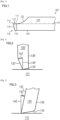
- Fig. 1 schematically illustrates a known cutting tool 100 having a cutting tool insert 110 and a shank body 120.
- the cutting tool insert 110 is formed by a base 111 and a cutting part 113 sintered together to form a sintered body composition as indicated by the broken line in Fig. 1 .
- the cutting tool insert 110 is fixed to the shank body 120 by brazing.
- the cutting tool insert 110 is allotted as a diamond sintered compact and a cBN sintered compact due to the expensive materials involved, particularly only the cutting part 113 being usually formed from cBN to provide an excellent abrasion resistance at the cutting tool insert 110.
- the cutting tool insert 110 further has a rake face 112 and a first flank face 114 which define a cutting edge there between.
- material of a workpiece (not illustrated) fed to the cutting edge chips along the rake face 112 of the cutting tool insert 110 while an inclination of the first flank face 114 with regard to the rake face 112 provides a clearance between the cutting tool insert and a workpiece surface (not illustrated), therefore no part of the cutting tool besides the cutting edge is in contact with the workpiece.
- the rake face 112 extends into the shank body 120 due to a rake face 122 formed on the shank body 120.
- the rake face 122 of the shank body 120 represents a curved surface which is curved such that a clearance between the rake face and a workpiece (the clearance on the rake face is often referred to as "chip pocket on the rake face”) is sufficient to receive the chip and to guide the chip away from the cutting edge.
- a second flank face 116 of the cutting tool insert 110 Adjacent to the first flank face of the cutting tool insert 110 a second flank face 116 of the cutting tool insert 110 is located, which a second flank face 116 extends into a flank face 124 of the shank body 120.
- the rake face 112 of the cutting tool insert 110 is aligned to a centre axis AI of the shank body 120. Therefore, the rake face 112 and the centre axis A1 coincide along the cutting tool insert 110, an according configuration being conventionally referred to as a "rake face with 0°".
- a cutting tool as discussed with regard to Fig. 1 is known from document JP 10128603 A .
- CN 2017 60617 U relates to a cBN pore boring and milling cutter which aims to meet the requirements of high speed, high precision and long service life of pore processing for modern automobile engine fuel nozzle parts.
- the CBN pore boring and milling cutter is characterized in that the radial relief angle of a tool is 3 degrees * 0.22mm and 35 degrees, the axial relief angle of the tool is 6 degrees * 0.2mm and 12 degrees, the nose angle of the tool is 77 degrees, the circular radius of a tool nose is 0.15mm, the radial negative front angle of the tool is 0 degree, the axial negative front angle of the tool is 5 degrees, the main drift angle of the tool is 100 degrees, the accessory drift angle of the tool is 3 degrees, the nose and a cutting edge of the tool are 0.
- the diameter of a handle of the tool ranges from 6mm to 0.011mm
- the end surface of a tool bit is abutted to a welding structure
- the tool bit is made of cubic boron nitride.
- the present invention has been made in order to solve the abovementioned problems of the prior art.
- a cutting tool comprising Cutting tool, comprising: a cutting tool insert with a tip portion of cBN material having a cutting edge formed, and a body portion coupling the cutting tool insert with a shank of the cutting tool, wherein the cutting tool insert has a rake face and a first flank face defining the cutting edge and a second flank face defining a further edge with the first flank face such that the cutting edge and the further edge do not have a common vertex, wherein the second flank face is tilted with respect to an axis A2 parallel to a centre axis A1 by an angle greater than 0°, wherein the centre axis A1 is the central longitudinal axis passing through the shank, and wherein an angle ⁇ 2 between the second flank face and the axis A2 parallel to the centre axis A1 is in a range from 25° to 60°, wherein the cutting tool insert comprises a base portion forming a sintered composition with the cBN tip portion,
- a method of manufacturing a cutting tool comprising providing a body portion coupling the cutting tool with a shank of the cutting tool, providing a cutting tool insert portion, performing a brazing process for connecting the cutting tool insert portion and the body portion at a common interface, forming a cutting edge in the cutting tool insert portion by performing a grinding process for removing material of the cutting tool insert portion in a part of the lateral surface of the cutting tool for forming a rake face in the cutting tool insert portion, and forming a first flank face in the cutting tool insert portion, the first flank face and the rake face defining the cutting edge; and forming a second flank face defining a further edge in the cutting tool insert portion, the cutting edge and the further edge not having a common vertex, wherein the second flank face is tilted with respect to an axis A4 parallel to a centre axisA1 by an angle greater than 0°, wherein the centre axis A1 is the central longitudinal axis passing through
- Fig. 2 illustrates a cutting tool 130' contacting a surface of a workpiece 131 for further processing.
- the cutting tool 130' has a rake face 132' and a first flank face 134' defining a cutting edge which is depicted in Fig. 2 as a contact vertex between the cutting tool 130' and the workpiece 131.
- the cutting tool 130' has a second flank face 136' in contact with the first flank face 134' such that a chip pocket is formed between the first flank face 134' and the surface of the workpiece 131.
- Line 140' indicates an axis parallel to a centre axis (not illustrated) of the cutting tool 130' which contacts the surface of the workpiece 131 in the cutting edge.
- the rake angle is defined by an angle 142' enclosed by the rake face 132' and the axis 140'.
- An orientation of the rake angle 142' is further defined such that a counter-clockwise rotation of the axis 140' by the angel 142' rotates the axis 140' into the rake face 132' defines the rake angle 142' to be negative, i.e. the rake angle 142' as depicted in Fig. 2 is referred to as "negative rake angle". Therefore, negative rake angles will be understood throughout the present description as oriented in accordance with the illustration in Fig. 2 and as explained above.
- Fig. 3 illustrates a cutting tool 130 disposed on the surface of a workpiece 131, the cutting tool 130 having a rake face 132, a first flank face 134 and a second flank face 136.
- the rake angle is defined by an angle 142 formed between the rake face 132 and an axis 140 parallel to a centre axis of the cutting tool 130 (not illustrated) and parallel to a surface normal the workpiece 131.
- a clockwise rotation of the axis 140 by the rake angle 142 rotates the axis 140 into the rake face 132 defines the rake angle to be negative, i.e. the rake angle 142 as depicted in Fig. 3 is referred to as "positive rake angle". Therefore, positive rake angles will be understood throughout the present description as oriented in accordance with the illustration in Fig. 3 and as explained above.
- the expression "negative rake angle” is to be understood in accordance with the explanations above provided with regard to Fig. 2
- the expression “positive rake angle” is to be understood in accordance with the explanations provided above with regard to Fig. 3 .
- the rake angle is referred to as "rake angle of 0° ".
- the cutting tool 100 as illustrated in Fig. 1 has a rake angle of 0°.
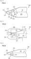
- Fig. 4 schematically illustrates a cutting tool 200 having a cutting tool insert 210 and a body portion 220 which may be, for example, formed of carbide and which couples the cutting tool insert 210 with a shank (not illustrated) of the cutting tool 200.
- the cutting tool insert 210 is a sintered composition of a tip portion formed of cBN material and a base portion formed of carbide material, both sintered together as will be described in greater detail below.
- the base portion may be formed of cermet.
- the cutting tool insert 210 has a rake face 212 and a first flank face 214 defining a cutting edge 216. Adjacent to the first flank face 214, a second flank face 218 is formed such that the first flank face 214 and the second flank face 218 define another edge that does not have a common vertex with the cutting edge 216.
- the expression "not having a vertex in common” means that the further edge defined by the first and second flank faces 214 and 218 and the cutting edge 216 do not intersect. It is noted that edges having a vertex in common are adjacent edges that join in a vertex.
- the body portion 220 has a rake face 222 joining the rake face 212 of the cutting insert tool.
- the special illustrative example shows the rake face 222 and the rake face 212 as forming a flat smooth rake surface of the cutting tool 200 (indicated in the cross sectional view of Fig. 4 as a single straight line).
- the body portion 220 further has a flank face 224 which represents a smooth extension of the second flank face 218 of the cutting tool 210 into the body portion 220 (indicated in the cross-section view of Fig. 4 as a single straight line).
- the rake face 212 of the cutting tool insert 210 and the rake face 222 of the body portion 220 form a smooth rake face in the cutting tool 200, as illustrated in Fig. 4 .
- the second flank face 218 and the flank face 224 form a smooth second flank face of the cutting tool 220. Therefore, the rake face 212, 222 of the cutting tool 200 is a flat face formed in the cutting tool insert 210 and the body portion 220.
- the second flank face 218, 224 of the cutting tool 220 is a flat face formed in the cutting tool insert 210 and the body portion 220.
- the rake face 212, 222 of the cutting tool 200 forms a negative rake angle THETA1 with an axis A2 of the body portion 220 which is substantially parallel to a centre axis (not illustrated) of the body portion 220 and intersects the cutting edge 216.
- the second flank face 218, 224 of the cutting tool 200 forms a second angle THETA2 with the axis A2.
- the negative rake angle THETA1 has an absolute value in a range from 5° to 40°.
- the negative rake angle THETA1 has an absolute value in a range from 10° to 30.
- he negative rake angle THETA1 may be chosen to balance the sharpness and toughness of the cutting edge 216.
- the negative rake angle THETA1 protects the cutting edge 216 and a brazing interface 226 of sufficient size is achieved between the cutting tool insert 210 and the body portion 220. Therefore, in spite of forming a second flank face 218, 224 being inclined relative to the axis A2 by the angle THETA2 for increasing a chip pocket volume on the second flank face 214, 218 of the cutting tool 200 (described below in greater detail), the brazing interface 226 is not reduced.
- the angle THETA2 has an absolute value in a range from 25° to 60°. Accordingly, the stability of the cutting tool 200 is increased by the negative rake angle THETA1.
- the negative rake angle THETA1 and the angle THETA2 are appropriately chosen such that the brazing interface 226 having an appropriate size is provided.
- the brazing interface 226 having a size given by diameter (indicated by line 226 in the cross-sectional view of Fig. 4 ) of at least 40% of a cutting tool diameter, such as a maximum diameter of the body portion 220, may be formed.
- a cutting tool diameter such as a maximum diameter of the body portion 220
- the angle THETA has an absolute value in a range from 35° to 70°.
- Fig. 5 illustrates the cutting tool 200 during processing of a hole 234 formed in a surface 232 of a workpiece 230.
- the hole 234 may represent a hole with very low inner diameter, such as for example diameters of 10 mm and less, or 5 mm and less.
- a region 240 indicates a chip pocket on the rake face 222 of the cutting tool 200, while a region 250 indicates a chip pocket on the second flank face 218, 224.
- the chip pocket 250 on the second flank face 218, 224 is considerably increased in size as compared to conventional cutting tools having a second flank face parallel to a tool centre axis. In this way, chip discharge properties at the second flank face are considerably improved in cutting tools provided by the present invention.
- the negative rake angle (c.f. THETA1 in Fig. 4 ) does not degrade the chip pocket 240 on the rake face 212, 222 of the cutting tool 200 and therefore, a protected cutting edge may be achieved by means of the negative rake angle without negatively affecting the chip discharge properties at the rake face 212, 222 of the cutting tool 200. Accordingly, the cutting tool 200 shows improved chip discharge properties as compared to conventional cutting tools.
- Fig. 6 illustrates a cutting tool 300 in accordance with an alternative embodiment of the present invention.
- the cutting tool 300 has a cutting tool insert 310 and a body portion 320 coupling the cutting tool insert 310 with a shank (not illustrated) of the cutting tool 300.
- the cutting tool insert 310 is a sintered composition of a tip portion of cBN material and a base portion of carbide material, similar to the configuration of the cutting tool insert 210 of the cutting tool 200 as described above with regard to Figs. 4 and 5 .
- the cutting tool 300 has a rake face 332 with a negative rake angle similar to the rake face 212, 222 of the cutting tool 200 as described above with regard to Figs. 4 and 5 .
- the cutting tool 300 may, alternatively or additionally, have a second flank face 338 besides a first flank face 334, wherein the second flank face 338 is inclined relative to an axis A3 in analogy to the configuration of the second flank face 218, 224 of the cutting tool 200 as described above with regard to Figs. 4 and 5 .
- the rake face 332 and the first flank face 334 define a cutting edge 336 of the cutting tool 300.
- the cutting tool 300 has a further increased brazing interface 340 as compared to the brazing interface 226 of the cutting tool 200 as described above with regard to Figs. 4 and 5 .
- the brazing interface 340 may be, for example, provided by a concave interface portion of the body portion 320 and a convex interface portion formed in the cutting tool insert 310 as shown in Fig. 6 .
- the convex interface portion of the cutting tool insert 310 and the concave interface portion of the body portion 320 are fabricated to match each other and the convex interface portion is received by the concave interface portion to form the stable brazing interface 340 upon connecting the cutting tool insert 310 and the body portion upon brazing.
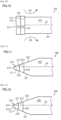
- FIG. 7 schematically illustrates a side sectional view of a cutting tool 400 having a cutting tool insert 410, a body portion 420 and a shank 430.
- the body portion 420 and the shank 430 are coupled together and may have a common contact interface.
- the contact interface may be, for example, located at the beginning of a tapered portion of the shank, as depicted in Fig. 7 , without posing any limitation to the present disclosure.
- the cutting tool insert 410 as depicted in Fig. 7 has a cutting edge 416 formed adjacent to a rake face 412 of the cutting tool insert 410.
- the body portion 420 has a rake face 422 adjacent to the rake face 412 of the cutting tool insert 410.
- the rake faces 412 and 422 form a smooth and flat rake face 412, 422 of the cutting tool 400 as illustrated in Fig. 7 .
- the person skilled in the art will appreciate that, although a configuration similar to the cutting tool 200 as discussed above with regard to Figs. 4 and 5 is depicted in Fig. 7 , this does not pose any limitation to the present description and alternatively a cutting tool configuration in accordance with the cutting tool 300 as described above with regard to Fig. 6 may be employed instead.
- the cutting tool 400 has a coolant hole 440 formed therein extending through the shank 430 and the body portion 420.
- An opening 450 of the coolant hole 440 is defined by the location of the coolant hole 440 relative to a centre axis (not illustrated) of the cutting tool 400 and depends on the negative rake angle as will be discussed in greater detail below.
- the opening 450 of the coolant hole 440 is located in the body portion 420.
- the opening 450 is formed within the rake face 422 of the body portion 420.
- an efficient provision of coolant means e.g. a coolant liquid or coolant gas, may be provided through the coolant hole 440 and the coolant opening 450 to a region close to the cutting tool insert 410 and the cutting edge 416.
- Fig. 8 illustrates a top view on the cutting tool 400 in a direction along the coolant hole 440 (c.f. Fig. 1 ).
- a grip portion 460 may be formed in the shank 430 indicating an orientation of the rake face 422.
- Fig. 9 illustrates a cutting tool 400' in a cross-sectional view.
- the cutting tool 400' has a cutting tool insert 410' and a body portion 420'.
- the cutting tool insert 410' has a rake face 412' with a negative rake angle and a first flank face 414' defining a cutting edge 416'.
- the cutting tool insert 410' has a second flank face 418' inclined by a non-negative angle relative to an axis 405' which extends parallel to a centre axis (not illustrated) of the body portion 420' through the cutting tool 400'.
- the cutting tool insert 410' and the body portion 420' are coupled by a brazing interface 430'.
- a configuration similar to the cutting tool 300 as discussed above with regard to Fig. 6 may be employed instead.
- the body portion 420' has a rake face 422' and a flank face 424'.
- the rake face 422' forms together with the rake face 412' a smooth flat rake face 412' 422' of the cutting tool 400', as depicted in Fig. 9 .
- the flank face 424' of the body portion 420' forms a second flank face 418', 424' of the cutting tool 400' together with the second flank face 418' of the cutting tool insert 410', as depicted in Fig. 9 .
- a coolant hole 440' is formed within the cutting tool 400' such that the coolant hole 440' is formed within the body portion 420'.
- the coolant hole 440' may extend through the body portion 420' in parallel to the axis 405'.
- An opening 450' of the coolant hole 440' may be formed in the rake face 412', 422' of the cutting tool 400'.
- the coolant hole 420' is formed in the rake face 422' of the body portion 420' and not in the rake face of the cutting tool insert 410'.
- the opening 450' of the coolant hole 440' may be only located in the rake face 422' of the body portion 420' and may not extend into the rake face 412' of the cutting tool insert 410'.
- an area of the opening 450' is greater than a cross-section of the coolant hole 440', as indicated in Fig. 9 by the double-arrow 453' which denotes the diameter of the coolant hole 440'.
- the diameter 453' equals the sine of the absolute value of the negative rake angle times the diameter 451'.
- a desired size of the opening 450' of the coolant hole 440' may be chosen.
- the opening 450' of the coolant hole 440' may be formed in the body portion 420' at minimal distance to the cutting edge 416'. Therefore, a direct supply of coolant means to the cutting tool insert 410' may be provided.
- an advantage of the present invention is to provide a coolant hole that comes into contact with the rake face of the cutting tool. Due to a wider opening of the coolant hole in the rake face with negative rake angle, a comparatively high volume of coolant may be provided to the cutting tool insert and the body portion.
- a shape of the opening 450' may be obtained, such as for example a complete "oval" shape if the coolant hole is disposed in an upper position relative to the axis 405', while an incomplete oval shape of the opening may be obtained in case that the coolant hole is at a position closer to the axis 405' and particularly closer to a centre axis (not illustrated) of the cutting tool.
- Fig. 10 depicts a cutting tool 500 at an early stage during fabrication, wherein a cutting tool insert portion 510 is coupled with a body portion 520.
- the coupling of the cutting tool insert portion 510 and the body portion 520 is achieved by performing a brazing process.
- a brazing process For example, titan, silver (as a main component) and copper may be used as a braze material to connect the cutting tool insert portion 510 with the body portion 520 in the brazing process. Accordingly, a brazing interface 522 is formed in the brazing process.
- the cutting tool insert portion may be provided herein as a sintered composite of a cBN material layer 511 and a carbide material layer 513.
- the sintered composition may be, for example, obtained by disposing a cBN material layer 511 on a carbide material layer 513 and performing a sintering process for sintering the cBN material layer 511 and the carbide material layer 513 together to give a cBN/carbide blank body 511, 513 as represented 510.
- the cBN/carbide blank body may be subsequently cut into shape to result in the cutting tool insert portion 510.
- a cylindrical blank body may be formed in this way.
- the cutting tool insert portion 510 may be, in accordance with a special illustrative example, of a cylindrical shape, having a top surface 512 of cBN material and a lower surface of carbide material for contacting the body portion 520.
- the cutting tool insert portion 510 Prior to brazing, the cutting tool insert portion 510 is disposed on the body portion 520 such that the top surface 512 and a lateral face 516 of the cutting tool insert portion 510 is exposed, while the lower face of the cutting tool insert portion 510 contacts a face of the body portion 520 which will provide the brazing interface 522 after the brazing process is completed.
- a first grinding process 532 is applied to the cutting tool 500 for removing material of the cutting tool insert portion 510 and the body portion 520 in a part of the lateral surface of the cutting tool 500.
- the grinding process 532 may be a grinding process employing a wheel grinder which therefore represents an easy grinding process.
- a second grinding process 534 may be applied to the cutting tool 500 at a side of the cutting tool 500 opposite to the previously-grinded lateral surface.
- the second grinding process may be performed employing a grinding wheel for easily performing the grinding process.
- the second grinding process may be performed prior to the first grinding process.
- Fig. 11 illustrates the cutting tool 500 at a later phase during fabrication, and particularly after the grinding processes 532 and 534 are completed.
- the first grinding process 532 resulted in a flat rake face 517 formed in the cutting tool insert portion 510' and a flat rake face 525 formed in the body portion 520.
- the rake faces 517 and 525 will form a smooth rake face 517, 525 of the cutting tool 500.
- a flat flank face 518 is formed in the cutting tool insert portion 510' and a flat flank face 527 is formed in the body portion 520.
- the flank faces 518 and 527 form a smooth flat flank face 518, 527 of the cutting tool 500. Furthermore, the upper surface 512 of the cutting tool insert portion 510' is effectively reduced to the reduced upper surface 512', while the brazing interface 522 is reduced to the brazing interface 523. As explained above, the brazing interface 523 is, in spite of the first and second grinding processes, still large enough to provide sufficient stability to the cutting tool 500. The person skilled in the art will appreciate that in appropriately choosing the negative rake angle of the rake face 517, 525 of the cutting tool 500 and an appropriate inclination of the flank face 518, 527, a desired size of the brazing interface 523 is obtained as pointed out above.
- the cutting tool insert portion 510' has shaped portions 511' and 513' representing a pre-processed tip portion (c.f. 511' in Fig. 11 ) and a base body 513'.
- Fig. 12 illustrates the cutting tool 500 at a more advanced stage during fabrication, particularly after a third grinding process has been performed.
- a first flank face 515 is formed in the top surface 512' (c.f. Fig. 11 ) of the tip portion 513' and a second flank face 518' is formed in the flank face 518 (c.f. Fig. 11 ).
- a coolant hole such as described above with regard to Figs. 7 to 9 may be provided in the cutting tool 500.
- a coolant hole may be formed within the cutting tool 500 after the brazing process is performed.
- a coolant hole may be provided within the body portion 520 prior to coupling the body portion 520 and the cutting tool insert portion 510, i.e. before the brazing process.
- a position of a coolant hole with regard to the axis A4 and in selecting a specific negative rake angle determines the size and shape of an opening of the coolant hole which will be formed in the rake face 525 of the body portion 520 (c.f. Fig. 11 ).
- Fig. 13 depicts a cutting tool 600 at an early stage during fabrication, wherein a cutting tool insert portion 610 is coupled with a body portion 620.
- the coupling of the cutting tool insert portion 610 and the body portion 620 is achieved by performing a brazing process.
- a brazing process For example, titan, silver (as a main component) and copper may be used as a braze material to connect the cutting tool insert portion 610 with the body portion 620 in the brazing process. Accordingly, a brazing interface 622 is formed in the brazing process.
- the cutting tool insert portion 610 may be provided herein as a sintered composite of a cBN material layer 611 and a carbide material layer 613.
- the sintered composition may be, for example, obtained by disposing a cBN material layer 611 on a carbide material layer 613 and performing a sintering process for sintering the cBN layer 611 and the carbide layer 613 to give a cBN/carbide blank body, e.g. a cylindrical blank body similar to the blank body 510 above.
- the cBN/carbide blank body may be cut into shape for forming a convex shaped carbide material layer 613 as illustrated in Fig.
- the cBN/carbide blank may be cut and grinded to obtain a convex surface portion in the carbide material layer, such as for example a wedge-shaped carbide layer portion as indicated by reference numeral 613 in Fig. 13 .
- a matching concave surface portion is formed in one of an upper or lower surface of the body portion 620 such that the concave surface portion 626 of the body portion 620 matches with the convex carbide layer portion 613 of the cutting tool insert portion 610.
- a wedge-shaped concave groove may be formed within the upper surface of the body portion 620.
- the cutting tool insert portion 610 may be, in accordance with a special illustrative example, of a cylindrical shape, having a top surface 612 of cBN material and a lower surface of carbide material for contacting the body portion 620.
- the cutting tool insert portion 610 is disposed on the body portion 620 such that the top surface 612 and a lateral face 616 of the cutting tool insert portion 610 is exposed, while the lower face of the cutting tool insert portion 610 contacts a face of the body portion 620 which will provide the brazing interface 622.
- a first grinding process (not illustrated) is applied to the cutting tool 600 for removing material of the cutting tool insert portion 610 and the body portion 620 in a part of the lateral surface of the cutting tool 600.
- the grinding process may be a grinding process employing a wheel grinder which therefore represents an easy grinding process.
- a second grinding process (not illustrated) may be applied to the cutting tool 600 at a side of the cutting tool 600 opposite to the previously-grinded lateral surface.
- the second grinding process may be performed employing a grinding wheel for easily performing the grinding process.
- the second grinding process may be performed prior to the first grinding process.
- Fig. 14 illustrates the cutting tool 600 at a later phase during fabrication, and particularly after the first and second grinding processes are completed.
- the first grinding process 632 resulted in a flat rake face 617 formed in the cutting tool insert portion 610 and a flat rake face 625 formed in the body portion 620.
- the rake faces 617 and 625 will form a smooth rake face 617, 625 of the cutting tool 600.
- a flat flank face 618 is formed in the cutting tool insert portion 610' and a flat flank face 627 is formed in the body portion 620.
- the flank faces 618 and 627 form a smooth flat flank face 618, 627 of the cutting tool 600. Furthermore, the upper surface 614 of the cutting tool insert portion 610' is effectively reduced to the reduced upper surface 614', while the brazing interface 626 is reduced to the brazing interface 630. As explained above, the brazing interface 630 is, in spite of the first and second grinding processes, still large enough to provide sufficient stability to the cutting tool 600. The person skilled in the art will appreciate that in appropriately choosing the negative rake angle of the rake face 617, 625 of the cutting tool 600 and an appropriate inclination of the flank face 618, 627, a desired size of the brazing interface 623 is obtained.
- Fig. 15 illustrates the cutting tool 600 at a more advanced stage during fabrication, particularly after a third grinding process has been performed.
- a first flank face 615 is formed in the top surface 612' (c.f. Fig. 14 ) and a second flank face 618' is formed in the flank face 618 (c.f. Fig. 14 ).
- a coolant hole such as described above with regard to Figs. 7 to 9 may be provided in the cutting tool 600.
- a coolant hole (not illustrated) may be formed within the cutting tool 600 after the brazing process is performed.
- a coolant hole may be provided within the body portion 620 prior to coupling the body portion 620 and the cutting tool insert portion 610, i.e. before the brazing process.
- a position of a coolant hole with regard to the axis A5 and in selecting a specific negative rake angle determines the size and shape of an opening of the coolant hole which will be formed in the rake face 625 of the body portion 620 (c.f. Fig. 14 ).
- a cutting tool may be fabricated similar to the cutting tool 300 as discussed above with regard to Fig. 6 .
- a chip pocket on the flank face may be increased, while still a brazing interface of more than 40% of a diameter of the cutting tool may be provided, such that an efficient bonding strength is obtained.
- a brazing interface of 40-50% of the diameter of the cutting tool may be obtained.
- Cutting tools as described above with regard to illustrative embodiments of the present disclosure may be in some illustrative applications employed in boring tools. Alternatively, cutting tools as described above may be employed in milling devices or lathe devices.
- cutting tools as described above may be in accordance with some special illustrative embodiments configured such that the centre axis intersects the cutting edge.
Landscapes
- Engineering & Computer Science (AREA)
- Mechanical Engineering (AREA)
- Physics & Mathematics (AREA)
- Geometry (AREA)
- Cutting Tools, Boring Holders, And Turrets (AREA)
Description
- The present invention relates to a cutting tool having a cutting tool insert with a negative rake angle and to a cutting tool having a cutting tool insert with a rake face and two flank faces, the rake face defining a cutting edge with a first of the two flank faces and a second flank face being tilted relative to a centre axis of the cutting tool by an angle greater than 0°. Furthermore, the present invention relates to a method of manufacturing respective cutting tools.
- Boring tools for processing hard materials, such as metal work pieces, having a cutting edge formed of cBN (cubic boron nitride) material are known in the art. For example, some known cutting tools have a cBN blank which is brazed to a shank of carbide material. Particularly, boron nitride is an attractive material because it has, besides diamond, a comparatively high abrasion resistance and particularly cubic boron nitride (cBN) is the second hardest material after diamond, while showing a chemical and thermal stability that is even greater than that of diamond. A high abrasion resistance and defect resistance is particularly desirable in the processing of boreholes with small inner diameter in hard materials for exactly and reproducibly processing. Despite having a high brittleness, cBN is also very expensive. Furthermore, due to its high hardness, cBN cannot be easily processed as compared to, for instance, metal materials.
-
Fig. 1 schematically illustrates a knowncutting tool 100 having a cutting tool insert 110 and ashank body 120. Thecutting tool insert 110 is formed by abase 111 and acutting part 113 sintered together to form a sintered body composition as indicated by the broken line inFig. 1 . Thecutting tool insert 110 is fixed to theshank body 120 by brazing. Usually, thecutting tool insert 110 is allotted as a diamond sintered compact and a cBN sintered compact due to the expensive materials involved, particularly only thecutting part 113 being usually formed from cBN to provide an excellent abrasion resistance at the cutting tool insert 110. - The
cutting tool insert 110 further has arake face 112 and afirst flank face 114 which define a cutting edge there between. In operation, material of a workpiece (not illustrated) fed to the cutting edge chips along therake face 112 of the cutting tool insert 110 while an inclination of thefirst flank face 114 with regard to therake face 112 provides a clearance between the cutting tool insert and a workpiece surface (not illustrated), therefore no part of the cutting tool besides the cutting edge is in contact with the workpiece. Therake face 112 extends into theshank body 120 due to arake face 122 formed on theshank body 120. Therake face 122 of theshank body 120 represents a curved surface which is curved such that a clearance between the rake face and a workpiece (the clearance on the rake face is often referred to as "chip pocket on the rake face") is sufficient to receive the chip and to guide the chip away from the cutting edge. - Adjacent to the first flank face of the cutting tool insert 110 a
second flank face 116 of thecutting tool insert 110 is located, which asecond flank face 116 extends into aflank face 124 of theshank body 120. - The
rake face 112 of thecutting tool insert 110 is aligned to a centre axis AI of theshank body 120. Therefore, therake face 112 and the centre axis A1 coincide along thecutting tool insert 110, an according configuration being conventionally referred to as a "rake face with 0°". - A cutting tool as discussed with regard to
Fig. 1 is known from documentJP 10128603 A -
CN 2017 60617 U relates to a cBN pore boring and milling cutter which aims to meet the requirements of high speed, high precision and long service life of pore processing for modern automobile engine fuel nozzle parts. The CBN pore boring and milling cutter is characterized in that the radial relief angle of a tool is 3 degrees * 0.22mm and 35 degrees, the axial relief angle of the tool is 6 degrees * 0.2mm and 12 degrees, the nose angle of the tool is 77 degrees, the circular radius of a tool nose is 0.15mm, the radial negative front angle of the tool is 0 degree, the axial negative front angle of the tool is 5 degrees, the main drift angle of the tool is 100 degrees, the accessory drift angle of the tool is 3 degrees, the nose and a cutting edge of the tool are 0. 25mm higher than a rotation center, the diameter of a handle of the tool ranges from 6mm to 0.011mm, the end surface of a tool bit is abutted to a welding structure, and the tool bit is made of cubic boron nitride. - PTL 1:
JP 10128603 A - In conventional cutting tools, such as the
cutting tool 100 shown inFig. 1 , an accurate formation of the rake face of the cutting tool insert and the shank body is not as exact as desired. Further, the chip pocket under the first flank face is very small and may not receive enough material as it is necessary when processing holes with very small inner diameter. The cutting chip discharge properties of known cutting tools do not allow a sufficiently exact processing of holes with very low inner diameter. - The present invention has been made in order to solve the abovementioned problems of the prior art.
- In one aspect of the present invention, a cutting tool is provided, the cutting tool comprising Cutting tool, comprising: a cutting tool insert with a tip portion of cBN material having a cutting edge formed, and a body portion coupling the cutting tool insert with a shank of the cutting tool, wherein the cutting tool insert has a rake face and a first flank face defining the cutting edge and a second flank face defining a further edge with the first flank face such that the cutting edge and the further edge do not have a common vertex, wherein the second flank face is tilted with respect to an axis A2 parallel to a centre axis A1 by an angle greater than 0°, wherein the centre axis A1 is the central longitudinal axis passing through the shank, and wherein an angle Θ2 between the second flank face and the axis A2 parallel to the centre axis A1 is in a range from 25° to 60°, wherein the cutting tool insert comprises a base portion forming a sintered composition with the cBN tip portion, the rake face of the cutting tool insert extends smoothly into the body portion forming a rake face in the body portion, the second flank face of the cutting tool insert extends smoothly into the body portion forming a second flank face in the body portion, and the rake face of the cutting tool insert and the rake face of the body portion form a same plane and the second flank face of the cutting tool insert and the second flank face of the body portion form a same plane.
- In another aspect of the present invention, a method of manufacturing a cutting tool is provided, the method comprising providing a body portion coupling the cutting tool with a shank of the cutting tool, providing a cutting tool insert portion, performing a brazing process for connecting the cutting tool insert portion and the body portion at a common interface, forming a cutting edge in the cutting tool insert portion by performing a grinding process for removing material of the cutting tool insert portion in a part of the lateral surface of the cutting tool for forming a rake face in the cutting tool insert portion, and forming a first flank face in the cutting tool insert portion, the first flank face and the rake face defining the cutting edge; and forming a second flank face defining a further edge in the cutting tool insert portion, the cutting edge and the further edge not having a common vertex, wherein the second flank face is tilted with respect to an axis A4 parallel to a centre axisA1 by an angle greater than 0°, wherein the centre axis A1 is the central longitudinal axis passing through the shank, and an angle Θ2 between the second flank face and the axis A2 parallel to the centre axis A1 is in a range from 25° to 60°, wherein the cutting tool insert comprises a base portion forming a sintered composition with the cBN tip portion, the rake face of the cutting tool insert extends smoothly into the body portion forming a rake face in the body portion, the second flank face of the cutting tool insert extends smoothly into the body portion forming a second flank face in the body portion, and the rake face of the cutting tool insert and the rake face of the body portion form a same plane and the second flank face of the cutting tool insert and the second flank face of the body portion form a same plane.
- It is an advantage of the aforementioned aspect to provide a greater chip pocket on the second flank face of a cutting tool insert.
- It is an advantage of the aforementioned aspect to increase the chip pocket on the second flank face of cutting tool inserts without reducing an interface between the cutting tool insert and a body portion coupling the cutting tool insert with a shank of the cutting tool.
- It is an advantage of the aforementioned aspect to allow for easier fabrication of the cutting edge especially for cutting tool inserts intended for use in the processing of holes with small diameters.
- It is an advantage of the aforementioned aspect to provide cutting tools with improved abrasion and cutting characteristics due to protected cutting edges.
- The a foregoing and other objects, features, aspects and advantages of the present invention will become more apparent from the following detailed description of the present invention when taken in conjunction with the accompanying drawings, wherein:
- [
fig. 1]Fig. 1 schematically illustrates a conventional cutting tool; - [
fig.2]Fig. 2 schematically illustrates different conventions for the rake angle as used in the present disclosure; - [
fig.3]Fig. 3 schematically illustrates different conventions for the rake angle as used in the present disclosure; - [
fig.4]Fig. 4 schematically illustrates a cutting tool in accordance with some illustrative embodiments of the present invention; - [
fig.5]Fig. 5 schematically illustrates a cutting tool in accordance with some illustrative embodiments of the present invention; - [
fig.6]Fig. 6 schematically illustrates a cutting tool in accordance with other illustrative embodiments of the present invention; - [
fig.7]Fig. 7 schematically illustrates cutting tools in accordance with still further illustrative embodiments of the present invention; - [
fig.8]Fig. 8 schematically illustrates cutting tools in accordance with still further illustrative embodiments of the present invention; - [
fig.9]Fig. 9 schematically illustrates cutting tools in accordance with still further illustrative embodiments of the present invention; - [
fig. 10]Fig. 10 schematically illustrates a method of fabricating a cutting tool in accordance with some illustrative embodiments of the present invention; - [
fig. 11 ]Fig. 11 schematically illustrates a method of fabricating a cutting tool in accordance with some illustrative embodiments of the present invention; - [
fig. 12]Fig. 12 schematically illustrates a method of fabricating a cutting tool in accordance with some illustrative embodiments of the present invention; - [
fig.13]Fig. 13 schematically illustrates a method in accordance with other illustrative embodiments of the present invention; - [
fig.14]Fig. 14 schematically illustrates a method in accordance with other illustrative embodiments of the present invention; and - [
fig.15] Fig. 15 schematically illustrates a method in accordance with other illustrative embodiments of the present invention. - With regard to
Figs. 2 and 3 , the expression "rake angle" as used throughout the present specification will be defined.Fig. 2 illustrates a cutting tool 130' contacting a surface of aworkpiece 131 for further processing. The cutting tool 130' has arake face 132' and a first flank face 134' defining a cutting edge which is depicted inFig. 2 as a contact vertex between the cutting tool 130' and theworkpiece 131. Furthermore, the cutting tool 130' has a second flank face 136' in contact with the first flank face 134' such that a chip pocket is formed between the first flank face 134' and the surface of theworkpiece 131. Line 140' indicates an axis parallel to a centre axis (not illustrated) of the cutting tool 130' which contacts the surface of theworkpiece 131 in the cutting edge. The rake angle is defined by an angle 142' enclosed by therake face 132' and the axis 140'. An orientation of the rake angle 142' is further defined such that a counter-clockwise rotation of the axis 140' by the angel 142' rotates the axis 140' into therake face 132' defines the rake angle 142' to be negative, i.e. the rake angle 142' as depicted inFig. 2 is referred to as "negative rake angle". Therefore, negative rake angles will be understood throughout the present description as oriented in accordance with the illustration inFig. 2 and as explained above. - On the other hand,
Fig. 3 illustrates acutting tool 130 disposed on the surface of aworkpiece 131, thecutting tool 130 having arake face 132, afirst flank face 134 and asecond flank face 136. Herein, the rake angle is defined by anangle 142 formed between therake face 132 and anaxis 140 parallel to a centre axis of the cutting tool 130 (not illustrated) and parallel to a surface normal theworkpiece 131. Herein, a clockwise rotation of theaxis 140 by therake angle 142 rotates theaxis 140 into therake face 132 defines the rake angle to be negative, i.e. therake angle 142 as depicted inFig. 3 is referred to as "positive rake angle". Therefore, positive rake angles will be understood throughout the present description as oriented in accordance with the illustration inFig. 3 and as explained above. - Therefore, the expression "negative rake angle" is to be understood in accordance with the explanations above provided with regard to
Fig. 2 , while the expression "positive rake angle" is to be understood in accordance with the explanations provided above with regard toFig. 3 . Additionally, in the case of therake angle 142' and 142, respectively, becoming 0, i.e. theaxis 140' and 140, respectively becoming identical with the rake face, the rake angle is referred to as "rake angle of 0° ". In this regard, thecutting tool 100 as illustrated inFig. 1 has a rake angle of 0°. - Some illustrative embodiments of the present invention will be now described with regard to
Figs. 4 and 5 . -
Fig. 4 schematically illustrates acutting tool 200 having acutting tool insert 210 and abody portion 220 which may be, for example, formed of carbide and which couples thecutting tool insert 210 with a shank (not illustrated) of thecutting tool 200. Thecutting tool insert 210 is a sintered composition of a tip portion formed of cBN material and a base portion formed of carbide material, both sintered together as will be described in greater detail below. In some alternative examples, the base portion may be formed of cermet. - The
cutting tool insert 210 has arake face 212 and afirst flank face 214 defining acutting edge 216. Adjacent to thefirst flank face 214, asecond flank face 218 is formed such that thefirst flank face 214 and thesecond flank face 218 define another edge that does not have a common vertex with thecutting edge 216. Herein, the expression "not having a vertex in common" means that the further edge defined by the first and second flank faces 214 and 218 and thecutting edge 216 do not intersect. It is noted that edges having a vertex in common are adjacent edges that join in a vertex. - The
body portion 220 has arake face 222 joining therake face 212 of the cutting insert tool. The special illustrative example, as illustrated inFig. 4 , shows therake face 222 and therake face 212 as forming a flat smooth rake surface of the cutting tool 200 (indicated in the cross sectional view ofFig. 4 as a single straight line). - The
body portion 220 further has aflank face 224 which represents a smooth extension of thesecond flank face 218 of thecutting tool 210 into the body portion 220 (indicated in the cross-section view ofFig. 4 as a single straight line). - The
rake face 212 of thecutting tool insert 210 and therake face 222 of thebody portion 220 form a smooth rake face in thecutting tool 200, as illustrated inFig. 4 . Thesecond flank face 218 and theflank face 224 form a smooth second flank face of thecutting tool 220. Therefore, therake face cutting tool 200 is a flat face formed in thecutting tool insert 210 and thebody portion 220. Furthermore, thesecond flank face cutting tool 220 is a flat face formed in thecutting tool insert 210 and thebody portion 220. - As depicted in
Fig. 4 , therake face cutting tool 200 forms a negative rake angle THETA1 with an axis A2 of thebody portion 220 which is substantially parallel to a centre axis (not illustrated) of thebody portion 220 and intersects thecutting edge 216. Thesecond flank face cutting tool 200 forms a second angle THETA2 with the axis A2. In special illustrative examples herein, the negative rake angle THETA1 has an absolute value in a range from 5° to 40°. In other special illustrative examples herein, the negative rake angle THETA1 has an absolute value in a range from 10° to 30. he negative rake angle THETA1 may be chosen to balance the sharpness and toughness of thecutting edge 216. The negative rake angle THETA1 protects thecutting edge 216 and abrazing interface 226 of sufficient size is achieved between the cuttingtool insert 210 and thebody portion 220. Therefore, in spite of forming asecond flank face second flank face brazing interface 226 is not reduced. The angle THETA2 has an absolute value in a range from 25° to 60°. Accordingly, the stability of thecutting tool 200 is increased by the negative rake angle THETA1. - In some illustrative embodiments, the negative rake angle THETA1 and the angle THETA2 are appropriately chosen such that the
brazing interface 226 having an appropriate size is provided. For example, thebrazing interface 226 having a size given by diameter (indicated byline 226 in the cross-sectional view ofFig. 4 ) of at least 40% of a cutting tool diameter, such as a maximum diameter of thebody portion 220, may be formed. Advantageously, in forming thesecond flank face cutting tool 200 is increased as will be described in greater detail with regard toFig. 5 below. Therefore in special illustrative examples herein the angle THETA has an absolute value in a range from 35° to 70°. -
Fig. 5 illustrates thecutting tool 200 during processing of ahole 234 formed in asurface 232 of aworkpiece 230. In some particular applications of the present invention, thehole 234 may represent a hole with very low inner diameter, such as for example diameters of 10 mm and less, or 5 mm and less. Aregion 240 indicates a chip pocket on therake face 222 of thecutting tool 200, while aregion 250 indicates a chip pocket on thesecond flank face Fig. 5 , thechip pocket 250 on thesecond flank face - On the side of the
rake face cutting tool 200, the negative rake angle (c.f. THETA1 inFig. 4 ) does not degrade thechip pocket 240 on therake face cutting tool 200 and therefore, a protected cutting edge may be achieved by means of the negative rake angle without negatively affecting the chip discharge properties at therake face cutting tool 200. Accordingly, thecutting tool 200 shows improved chip discharge properties as compared to conventional cutting tools. -
Fig. 6 illustrates acutting tool 300 in accordance with an alternative embodiment of the present invention. Thecutting tool 300 has acutting tool insert 310 and abody portion 320 coupling thecutting tool insert 310 with a shank (not illustrated) of thecutting tool 300. For example, thecutting tool insert 310 is a sintered composition of a tip portion of cBN material and a base portion of carbide material, similar to the configuration of thecutting tool insert 210 of thecutting tool 200 as described above with regard toFigs. 4 and 5 . - The
cutting tool 300 has arake face 332 with a negative rake angle similar to therake face cutting tool 200 as described above with regard toFigs. 4 and 5 . Furthermore, thecutting tool 300 may, alternatively or additionally, have asecond flank face 338 besides afirst flank face 334, wherein thesecond flank face 338 is inclined relative to an axis A3 in analogy to the configuration of thesecond flank face cutting tool 200 as described above with regard toFigs. 4 and 5 . Therake face 332 and thefirst flank face 334 define acutting edge 336 of thecutting tool 300. - The
cutting tool 300 has a further increasedbrazing interface 340 as compared to thebrazing interface 226 of thecutting tool 200 as described above with regard toFigs. 4 and 5 . Thebrazing interface 340 may be, for example, provided by a concave interface portion of thebody portion 320 and a convex interface portion formed in thecutting tool insert 310 as shown inFig. 6 . Particularly, the convex interface portion of thecutting tool insert 310 and the concave interface portion of thebody portion 320 are fabricated to match each other and the convex interface portion is received by the concave interface portion to form thestable brazing interface 340 upon connecting thecutting tool insert 310 and the body portion upon brazing. - With regard to
Figs. 7 to 9 , some illustrative embodiments of the present invention will be described in greater detail.Fig. 7 schematically illustrates a side sectional view of acutting tool 400 having acutting tool insert 410, abody portion 420 and ashank 430. Thebody portion 420 and theshank 430 are coupled together and may have a common contact interface. The contact interface may be, for example, located at the beginning of a tapered portion of the shank, as depicted inFig. 7 , without posing any limitation to the present disclosure. - The
cutting tool insert 410 as depicted inFig. 7 has acutting edge 416 formed adjacent to arake face 412 of thecutting tool insert 410. Thebody portion 420 has arake face 422 adjacent to therake face 412 of thecutting tool insert 410. The rake faces 412 and 422 form a smooth andflat rake face cutting tool 400 as illustrated inFig. 7 . The person skilled in the art will appreciate that, although a configuration similar to thecutting tool 200 as discussed above with regard toFigs. 4 and 5 is depicted inFig. 7 , this does not pose any limitation to the present description and alternatively a cutting tool configuration in accordance with thecutting tool 300 as described above with regard toFig. 6 may be employed instead. - The
cutting tool 400 has acoolant hole 440 formed therein extending through theshank 430 and thebody portion 420. Anopening 450 of thecoolant hole 440 is defined by the location of thecoolant hole 440 relative to a centre axis (not illustrated) of thecutting tool 400 and depends on the negative rake angle as will be discussed in greater detail below. Theopening 450 of thecoolant hole 440 is located in thebody portion 420. In special examples, theopening 450 is formed within therake face 422 of thebody portion 420. In this way, an efficient provision of coolant means, e.g. a coolant liquid or coolant gas, may be provided through thecoolant hole 440 and thecoolant opening 450 to a region close to thecutting tool insert 410 and thecutting edge 416. -
Fig. 8 illustrates a top view on thecutting tool 400 in a direction along the coolant hole 440 (c.f.Fig. 1 ). For example, agrip portion 460 may be formed in theshank 430 indicating an orientation of therake face 422. -
Fig. 9 illustrates a cutting tool 400' in a cross-sectional view. The cutting tool 400' has a cutting tool insert 410' and a body portion 420'. The cutting tool insert 410' has a rake face 412' with a negative rake angle and a first flank face 414' defining a cutting edge 416'. Furthermore, the cutting tool insert 410' has a second flank face 418' inclined by a non-negative angle relative to an axis 405' which extends parallel to a centre axis (not illustrated) of the body portion 420' through the cutting tool 400'. As indicated by the broken line 430', the cutting tool insert 410' and the body portion 420' are coupled by a brazing interface 430'. In spite of the illustrated configuration similar to thecutting tool 200 as discussed above with regard toFigs. 4 and 5 , in an alternative embodiment herein, a configuration similar to thecutting tool 300 as discussed above with regard toFig. 6 may be employed instead. - The body portion 420' has a rake face 422' and a flank face 424'. The rake face 422' forms together with the rake face 412' a smooth flat rake face 412' 422' of the cutting tool 400', as depicted in
Fig. 9 . The flank face 424' of the body portion 420' forms a second flank face 418', 424' of the cutting tool 400' together with the second flank face 418' of the cutting tool insert 410', as depicted inFig. 9 . - A coolant hole 440' is formed within the cutting tool 400' such that the coolant hole 440' is formed within the body portion 420'. In accordance with illustrative embodiments, the coolant hole 440' may extend through the body portion 420' in parallel to the axis 405'. An opening 450' of the coolant hole 440' may be formed in the rake face 412', 422' of the cutting tool 400'. In some illustrative embodiments, the coolant hole 420' is formed in the rake face 422' of the body portion 420' and not in the rake face of the cutting tool insert 410'. The person skilled in the art will appreciate that due to the hardness of the cutting tool insert 410', the opening 450' of the coolant hole 440' may be only located in the rake face 422' of the body portion 420' and may not extend into the rake face 412' of the cutting tool insert 410'.
- Depending on the negative rake angle of the rake face 412', 422' of the cutting tool 400', an area of the opening 450', indicated in
Fig. 9 by double-arrow 451' denoting a diameter of the opening, is greater than a cross-section of the coolant hole 440', as indicated inFig. 9 by the double-arrow 453' which denotes the diameter of the coolant hole 440'. Particularly, the diameter 453' equals the sine of the absolute value of the negative rake angle times the diameter 451'. In appropriately choosing the negative rake angle, a desired size of the opening 450' of the coolant hole 440' may be chosen. In this way, an efficient cooling of the cutting device 400', particularly of the cutting tool insert 410' and the body portion 420', may be achieved. Particularly, the opening 450' of the coolant hole 440' may be formed in the body portion 420' at minimal distance to the cutting edge 416'. Therefore, a direct supply of coolant means to the cutting tool insert 410' may be provided. - In adjusting a relative lateral displacement of the coolant hole 440' relative to the axis 405' an amount of opening within the rake face 412' of the cutting tool insert 410' and in the rake face 422' of the body portion 420' may be adjusted. Therefore, an advantage of the present invention is to provide a coolant hole that comes into contact with the rake face of the cutting tool. Due to a wider opening of the coolant hole in the rake face with negative rake angle, a comparatively high volume of coolant may be provided to the cutting tool insert and the body portion.
- It is further noted that, depending on the position of the coolant hole relative to the axis 405', a shape of the opening 450' may be obtained, such as for example a complete "oval" shape if the coolant hole is disposed in an upper position relative to the axis 405', while an incomplete oval shape of the opening may be obtained in case that the coolant hole is at a position closer to the axis 405' and particularly closer to a centre axis (not illustrated) of the cutting tool.
- With regard to
Figs. 10 to 12 , a method of fabricating a cutting tool in accordance with some illustrative embodiments of the present invention will be described. -
Fig. 10 depicts acutting tool 500 at an early stage during fabrication, wherein a cuttingtool insert portion 510 is coupled with abody portion 520. The coupling of the cuttingtool insert portion 510 and thebody portion 520 is achieved by performing a brazing process. For example, titan, silver (as a main component) and copper may be used as a braze material to connect the cuttingtool insert portion 510 with thebody portion 520 in the brazing process. Accordingly, abrazing interface 522 is formed in the brazing process. - The cutting tool insert portion may be provided herein as a sintered composite of a
cBN material layer 511 and acarbide material layer 513. The sintered composition may be, for example, obtained by disposing acBN material layer 511 on acarbide material layer 513 and performing a sintering process for sintering thecBN material layer 511 and thecarbide material layer 513 together to give a cBN/carbideblank body tool insert portion 510. For example, a cylindrical blank body may be formed in this way. - The cutting
tool insert portion 510 may be, in accordance with a special illustrative example, of a cylindrical shape, having atop surface 512 of cBN material and a lower surface of carbide material for contacting thebody portion 520. - Prior to brazing, the cutting
tool insert portion 510 is disposed on thebody portion 520 such that thetop surface 512 and alateral face 516 of the cuttingtool insert portion 510 is exposed, while the lower face of the cuttingtool insert portion 510 contacts a face of thebody portion 520 which will provide thebrazing interface 522 after the brazing process is completed. - Subsequently to the brazing process, a
first grinding process 532 is applied to thecutting tool 500 for removing material of the cuttingtool insert portion 510 and thebody portion 520 in a part of the lateral surface of thecutting tool 500. In some special illustrative example, the grindingprocess 532 may be a grinding process employing a wheel grinder which therefore represents an easy grinding process. - Subsequent to the
first grinding process 532, asecond grinding process 534 may be applied to thecutting tool 500 at a side of thecutting tool 500 opposite to the previously-grinded lateral surface. In a special illustrative example herein, the second grinding process may be performed employing a grinding wheel for easily performing the grinding process. - Alternatively, the second grinding process may be performed prior to the first grinding process.
-
Fig. 11 illustrates thecutting tool 500 at a later phase during fabrication, and particularly after the grinding processes 532 and 534 are completed. Particularly, thefirst grinding process 532 resulted in aflat rake face 517 formed in the cutting tool insert portion 510' and aflat rake face 525 formed in thebody portion 520. In applications relating to cutting tools configured to process low diameter holes, the rake faces 517 and 525 will form asmooth rake face cutting tool 500. As a result of thesecond grinding process 534, aflat flank face 518 is formed in the cutting tool insert portion 510' and aflat flank face 527 is formed in thebody portion 520. In cutting tools configured to perform inner diameter processing in low diameter holes, the flank faces 518 and 527 form a smoothflat flank face cutting tool 500. Furthermore, theupper surface 512 of the cutting tool insert portion 510' is effectively reduced to the reduced upper surface 512', while thebrazing interface 522 is reduced to thebrazing interface 523. As explained above, thebrazing interface 523 is, in spite of the first and second grinding processes, still large enough to provide sufficient stability to thecutting tool 500. The person skilled in the art will appreciate that in appropriately choosing the negative rake angle of therake face cutting tool 500 and an appropriate inclination of theflank face brazing interface 523 is obtained as pointed out above. - After having completed the grinding processes 532, 534, the cutting tool insert portion 510' has shaped
portions 511' and 513' representing a pre-processed tip portion (c.f. 511' inFig. 11 ) and a base body 513'. -
Fig. 12 illustrates thecutting tool 500 at a more advanced stage during fabrication, particularly after a third grinding process has been performed. As a result of the third grinding process, afirst flank face 515 is formed in the top surface 512' (c.f.Fig. 11 ) of the tip portion 513' and a second flank face 518' is formed in the flank face 518 (c.f.Fig. 11 ). - In additional processing steps, a coolant hole, such as described above with regard to
Figs. 7 to 9 may be provided in thecutting tool 500. The person skilled in the art will appreciate that prior to performing the first and second grinding processes 532 and 534 (c.f.Fig. 10 above), a coolant hole (not illustrated) may be formed within thecutting tool 500 after the brazing process is performed. Alternatively, a coolant hole may be provided within thebody portion 520 prior to coupling thebody portion 520 and the cuttingtool insert portion 510, i.e. before the brazing process. The person skilled in the art will appreciate that a position of a coolant hole with regard to the axis A4 and in selecting a specific negative rake angle, determines the size and shape of an opening of the coolant hole which will be formed in therake face 525 of the body portion 520 (c.f.Fig. 11 ). - With regard to
Figs. 13 to 15 , a method of fabricating a cutting tool in accordance with some other illustrative embodiments of the present invention will be described. -
Fig. 13 depicts acutting tool 600 at an early stage during fabrication, wherein a cuttingtool insert portion 610 is coupled with abody portion 620. The coupling of the cuttingtool insert portion 610 and thebody portion 620 is achieved by performing a brazing process. For example, titan, silver (as a main component) and copper may be used as a braze material to connect the cuttingtool insert portion 610 with thebody portion 620 in the brazing process. Accordingly, abrazing interface 622 is formed in the brazing process. - The cutting
tool insert portion 610 may be provided herein as a sintered composite of acBN material layer 611 and acarbide material layer 613. The sintered composition may be, for example, obtained by disposing acBN material layer 611 on acarbide material layer 613 and performing a sintering process for sintering thecBN layer 611 and thecarbide layer 613 to give a cBN/carbide blank body, e.g. a cylindrical blank body similar to theblank body 510 above. In a subsequent process, the cBN/carbide blank body may be cut into shape for forming a convex shapedcarbide material layer 613 as illustrated inFig. 13 , thereby resulting in the cuttingtool insert portion 610 as depicted inFig. 13 . For example, the cBN/carbide blank may be cut and grinded to obtain a convex surface portion in the carbide material layer, such as for example a wedge-shaped carbide layer portion as indicated byreference numeral 613 inFig. 13 . Furthermore, a matching concave surface portion is formed in one of an upper or lower surface of thebody portion 620 such that theconcave surface portion 626 of thebody portion 620 matches with the convexcarbide layer portion 613 of the cuttingtool insert portion 610. For example, a wedge-shaped concave groove may be formed within the upper surface of thebody portion 620. - The cutting
tool insert portion 610 may be, in accordance with a special illustrative example, of a cylindrical shape, having atop surface 612 of cBN material and a lower surface of carbide material for contacting thebody portion 620. The cuttingtool insert portion 610 is disposed on thebody portion 620 such that thetop surface 612 and alateral face 616 of the cuttingtool insert portion 610 is exposed, while the lower face of the cuttingtool insert portion 610 contacts a face of thebody portion 620 which will provide thebrazing interface 622. - Subsequently to the brazing, a first grinding process (not illustrated) is applied to the
cutting tool 600 for removing material of the cuttingtool insert portion 610 and thebody portion 620 in a part of the lateral surface of thecutting tool 600. In some special illustrative example, the grinding process may be a grinding process employing a wheel grinder which therefore represents an easy grinding process. - Subsequent to the first grinding process, a second grinding process (not illustrated) may be applied to the
cutting tool 600 at a side of thecutting tool 600 opposite to the previously-grinded lateral surface. In a special illustrative example herein, the second grinding process may be performed employing a grinding wheel for easily performing the grinding process. - Alternatively, the second grinding process may be performed prior to the first grinding process.
-
Fig. 14 illustrates thecutting tool 600 at a later phase during fabrication, and particularly after the first and second grinding processes are completed. Particularly, the first grinding process 632 resulted in aflat rake face 617 formed in the cuttingtool insert portion 610 and aflat rake face 625 formed in thebody portion 620. For cutting tools configured to process low diameter holes, the rake faces 617 and 625 will form asmooth rake face cutting tool 600. As a result of the second grinding process 634, aflat flank face 618 is formed in the cutting tool insert portion 610' and aflat flank face 627 is formed in thebody portion 620. In cutting tools configured to perform inner diameter processing in low diameter holes, the flank faces 618 and 627 form a smoothflat flank face cutting tool 600. Furthermore, theupper surface 614 of the cutting tool insert portion 610' is effectively reduced to the reduced upper surface 614', while thebrazing interface 626 is reduced to thebrazing interface 630. As explained above, thebrazing interface 630 is, in spite of the first and second grinding processes, still large enough to provide sufficient stability to thecutting tool 600. The person skilled in the art will appreciate that in appropriately choosing the negative rake angle of therake face cutting tool 600 and an appropriate inclination of theflank face -
Fig. 15 illustrates thecutting tool 600 at a more advanced stage during fabrication, particularly after a third grinding process has been performed. As a result of the third grinding process, afirst flank face 615 is formed in the top surface 612' (c.f.Fig. 14 ) and a second flank face 618' is formed in the flank face 618 (c.f.Fig. 14 ). - In additional processing steps, a coolant hole, such as described above with regard to
Figs. 7 to 9 may be provided in thecutting tool 600. The person skilled in the art will appreciate that prior to performing the first and second grinding processes, a coolant hole (not illustrated) may be formed within thecutting tool 600 after the brazing process is performed. Alternatively, a coolant hole may be provided within thebody portion 620 prior to coupling thebody portion 620 and the cuttingtool insert portion 610, i.e. before the brazing process. The person skilled in the art will appreciate that a position of a coolant hole with regard to the axis A5 and in selecting a specific negative rake angle, determines the size and shape of an opening of the coolant hole which will be formed in therake face 625 of the body portion 620 (c.f.Fig. 14 ). - Accordingly, in performing the method as described above with regard to
Figs. 13 to 15 , a cutting tool may be fabricated similar to thecutting tool 300 as discussed above with regard toFig. 6 . - The person skilled in the art will appreciate that in providing a rake face with negative rake angle and an inclined flank face, a chip pocket on the flank face may be increased, while still a brazing interface of more than 40% of a diameter of the cutting tool may be provided, such that an efficient bonding strength is obtained. The person skilled in the art will appreciate that, depending on the rake angle and the inclination, a brazing interface of 40-50% of the diameter of the cutting tool may be obtained.
- Cutting tools as described above with regard to illustrative embodiments of the present disclosure may be in some illustrative applications employed in boring tools. Alternatively, cutting tools as described above may be employed in milling devices or lathe devices.
- The person skilled in the art will appreciate that in providing a cutting tool with a centre axis intersecting the cutting edge, a special symmetrical configuration of the cutting tool is provided which may be further stabilized when compared to cutting tools having centre axis that do not intersect the cutting edge. Accordingly, cutting tools as described above may be in accordance with some special illustrative embodiments configured such that the centre axis intersects the cutting edge.
- 100, 130', 200, 300, 400, 400', 500, 600 cutting tool, 110, 210, 310, 410, 410' cutting tool insert, 111 base, 112, 122, 132', 212, 222, 332, 412, 412', 422, 422', 517, 525 rake face, 113 cutting part, 114, 134, 134', 214, 334, 414', 515, 615 first flank face, 116, 136, 136', 218, 224, 338, 418', 518', 618' second flank face, 120 shank body, 124,418', 424' flank face, 131 workpiece, 140' axis, 142, 142' angle, 216, 336, 416, 416' cutting edge, 220, 320, 420, 420', 520, 620 body portion, 226, 340, 430', 522, 523, 622, 626, 630 brazing interface, 232 surface, 234 hole, 240, 250 region, 405' axis, 430 shank, 440, 440' coolant hole, 450, 450' opening, 460 grip portion, 510, 510', 610, 610' cutting tool insert portion, 511,611 cBN material layer, 511', 513' shaped portion, 512, 512', 612 top surface, 513, 613 carbide material layer, 513' tip portion, 516, 616 lateral face, 517, 525, 617, 625 flat rake face, 518, 527, 618, 627 flat flank face, 614, 614' upper surface, 626 concave surface portion.
Claims (8)
- Cutting tool (200, 300, 400), comprising:a cutting tool insert (210) with a tip portion of cBN material having a cutting edge (216) formed therein, anda body portion (220) coupling the cutting tool insert (210) with a shank of the cutting tool (200),wherein the cutting tool insert (210) has a rake face (212) and a first flank face (214) defining the cutting edge (216) and a second flank face (218) defining a further edge with the first flank face (214) such that the cutting edge (216) and the further edge do not have a common vertex, wherein the second flank face (218) is tilted with respect to an axis (A2) parallel to a centre axis (A1) by an angle greater than 0°,wherein the centre axis (A1) is the central longitudinal axis passing through the shank, and wherein an angle Θ2 between the second flank face (218) and the axis (A2) parallel to the centre axis (A1) is in a range from 25° to 60°, whereinthe cutting tool insert (210) comprises a base portion forming a sintered composition with the cBN tip portion,the rake face (212) of the cutting tool insert (210) extends smoothly into the body portion (220) forming a rake face (222) in the body portion (220),the second flank face (218) of the cutting tool insert (210) extends smoothly into the body portion (220) forming a second flank face (224) in the body portion (220), andthe rake face (212) of the cutting tool insert (210) and the rake face (222) of the body portion (220) form a same plane and the second flank face (218) of the cutting tool insert (210) and the second flank face (224) of the body portion (220) form a same plane.
- Cutting tool (200, 300, 400) in accordance with claim 1, wherein an angle Θ between the rake face (212) and the second flank face (218) is in a range from 35° to 70°.
- Cutting tool in accordance with claim 1 or 2, wherein an angle Θ1 between the rake face and the axis parallel to a centre axis of the body portion is in a range from 5° to 40°.
- Cutting tool (200, 300, 400) in accordance with one of claims 1 to 3, wherein the cutting edge (216) is smaller than 5 mm.
- Cutting tool (200, 300, 400) in accordance with one of claims 1 to 4, wherein the base portion and the body portion (220) are of carbide material and form a brazed composition.
- Cutting tool (200, 300, 400) in accordance with one of claims 1 to 5, wherein the body portion (320) has a concave interface portion and the base portion has a convex interface portion matching the concave interface portion such that the convex interface portion is received by the concave interface portion.
- Cutting tool (200, 300, 400) in accordance with one of claims 1 to 6, further comprising a coolant hole (440) formed within the body portion (420) and extending through the body portion (420) along a direction parallel to the axis of the body portion (420), wherein the rake face (422) of the cutting tool insert (410) extends smoothly into the body portion (420) forming a rake face in the body portion (420) and the opening (450) of the coolant hole (440) being located within the rake face of the body portion.
- Method of manufacturing a cutting tool (500), the method comprising:providing a body portion (520) coupling the cutting tool with a shank of the cutting tool;providing a cutting tool insert portion (510');performing a brazing process for connecting the cutting tool insert portion (510') and the body portion (520) at a common interface;forming a cutting edge in the cutting tool insert portion (510') by performing a grinding process (532, 534) for removing material of the cutting tool insert portion (510) in a part of the lateral surface of the cutting tool (500) for forming a rake face (517) in the cutting tool insert portion (510'),and forming a first flank face in the cutting tool insert portion, the first flank face and the rake face defining the cutting edge; andforming a second flank face defining a further edge in the cutting tool insert portion, the cutting edge and the further edge not having a common vertex,wherein the second flank face (518') is tilted with respect to an axis (A4) parallel to a centre axis (A1) by an angle greater than 0°,wherein the centre axis (A1) is the central longitudinal axis passing through the shank, andan angle Θ2 between the second flank face (218) and the axis (A2) parallel to the centre axis (A1) is in a range from 25° to 60°,the rake face (212) of the cutting tool insert (210) extends smoothly into the body portion (220) forming a rake face (222) in the body portion (220),the second flank face (218) of the cutting tool insert (210) extends smoothly into the body portion (220) forming a second flank face (224) in the body portion (220), andthe rake face (212) of the cutting tool insert (210) and the rake face (222) of the body portion (220) form a same plane and the second flank face (218) of the cutting tool insert (210) and the second flank face (224) of the body portion (220) form a same plane.
Applications Claiming Priority (1)
| Application Number | Priority Date | Filing Date | Title |
|---|---|---|---|
| PCT/JP2014/003358 WO2015198361A1 (en) | 2014-06-23 | 2014-06-23 | Cutting tool and method of manufacturing a cutting tool |
Publications (2)
| Publication Number | Publication Date |
|---|---|
| EP3157698A1 EP3157698A1 (en) | 2017-04-26 |
| EP3157698B1 true EP3157698B1 (en) | 2023-03-08 |
Family
ID=51211826
Family Applications (1)
| Application Number | Title | Priority Date | Filing Date |
|---|---|---|---|
| EP14741683.8A Active EP3157698B1 (en) | 2014-06-23 | 2014-06-23 | Cutting tool and method of manufacturing a cutting tool |
Country Status (5)
| Country | Link |
|---|---|
| US (1) | US10040126B2 (en) |
| EP (1) | EP3157698B1 (en) |
| JP (1) | JP6465367B2 (en) |
| CN (1) | CN106573314B (en) |
| WO (1) | WO2015198361A1 (en) |
Families Citing this family (6)
| Publication number | Priority date | Publication date | Assignee | Title |
|---|---|---|---|---|
| CA3149800C (en) * | 2017-07-28 | 2025-03-11 | Cricut, Inc. | Crafting apparatus assemblies, systems, devices, kits, mechanisms and methodologies for utilizing the same |
| JP6651136B2 (en) * | 2017-10-25 | 2020-02-19 | 株式会社タンガロイ | Cutting inserts, deposits and holders |
| CN108405893A (en) * | 2018-03-01 | 2018-08-17 | 重庆建设汽车系统股份有限公司 | A kind of cutter and its processing method for processing shoulder hole |
| CN108971531A (en) * | 2018-06-11 | 2018-12-11 | 江苏科比特科技有限公司 | Turning high-gloss blade |
| JP7038415B2 (en) * | 2019-03-06 | 2022-03-18 | 国立大学法人東海国立大学機構 | Diamond coating tool |
| CN110000400B (en) * | 2019-04-03 | 2024-07-12 | 株洲欧科亿数控精密刀具股份有限公司 | Double-sided groove type cutting blade |
Family Cites Families (32)
| Publication number | Priority date | Publication date | Assignee | Title |
|---|---|---|---|---|
| US938434A (en) * | 1906-07-17 | 1909-10-26 | Lanston Monotype Machine Co | Cutter for punch-cutting machines. |
| US3184242A (en) * | 1963-04-19 | 1965-05-18 | Capps & Co Inc | Recording stylus |
| US4260299A (en) * | 1979-05-25 | 1981-04-07 | The Gleason Works | Cutting tools having compound cutting faces |
| US5022797A (en) * | 1985-09-09 | 1991-06-11 | Hitachi, Ltd. | Diamond tool |
| JPH0613764Y2 (en) | 1988-01-08 | 1994-04-13 | 三菱マテリアル株式会社 | Cutting tool with ultra-high pressure sintered body |
| US5149234A (en) * | 1991-08-16 | 1992-09-22 | Unibit Corporation | Spot-weld removing tool |
| US5209612A (en) * | 1992-03-27 | 1993-05-11 | The Budd Company | Cutting tool |
| US5272940A (en) * | 1992-06-09 | 1993-12-28 | Dico Corporation | Helically fluted tool |
| CN2150947Y (en) * | 1992-10-27 | 1993-12-29 | 国家建筑材料工业局人工晶体研究所 | Cubic boron nitride composite tool bit |
| US5374142A (en) * | 1992-12-03 | 1994-12-20 | Dana Corporation | Tip relief cutter blades |
| US5362183A (en) * | 1993-10-05 | 1994-11-08 | Joseph Alario | Single point cutting tool |
| JP2929181B2 (en) | 1996-02-08 | 1999-08-03 | 大阪ダイヤモンド工業株式会社 | Cutting inserts and rotary cutting tools |
| JPH10128603A (en) | 1996-10-30 | 1998-05-19 | Kyocera Corp | Indexable cutting tool for internal machining |
| JPH10193203A (en) * | 1997-01-08 | 1998-07-28 | Mitsubishi Materials Corp | Indexable insert and method of manufacturing the same |
| SE512752C2 (en) | 1997-06-13 | 2000-05-08 | Sandvik Ab | Ways to make stick cutters |
| US6095723A (en) * | 1999-01-19 | 2000-08-01 | Nemco Medical | Engraving tool and method for forming |
| US6491481B1 (en) * | 2000-10-31 | 2002-12-10 | Eastman Kodak Company | Method of making a precision microlens mold and a microlens mold |
| JP2003071608A (en) * | 2001-08-28 | 2003-03-12 | Mitsubishi Materials Corp | Cutting tools |
| US7140812B2 (en) * | 2002-05-29 | 2006-11-28 | 3M Innovative Properties Company | Diamond tool with a multi-tipped diamond |
| US7178433B2 (en) * | 2003-03-27 | 2007-02-20 | Konica Minolta Holdings, Inc. | Processing apparatus, processing method and diamond tool |
| DE20307124U1 (en) | 2003-04-29 | 2003-07-03 | MAS Vertriebsgesellschaft für Zerspanungstechnik mbH, 71229 Leonberg | Tool suitable for working at inside of metal workpiece, comprising shaft with longitudinal slot and particularly designed cutting head |
| US7322776B2 (en) | 2003-05-14 | 2008-01-29 | Diamond Innovations, Inc. | Cutting tool inserts and methods to manufacture |
| DE202004002491U1 (en) * | 2004-02-17 | 2005-08-18 | Kennametal Inc. | Cutting plate, in particular for a boring tool |
| WO2005102572A1 (en) * | 2004-04-20 | 2005-11-03 | Osg Corporation | Ball end mill |
| US8656815B2 (en) * | 2004-12-06 | 2014-02-25 | Konica Minolta Opto, Inc. | Transfer optical surface machining method, optical device producing mold and optical device |
| US7240593B2 (en) * | 2005-04-19 | 2007-07-10 | Roger Little | Miniature cutting insert holder |
| WO2007103939A2 (en) * | 2006-03-06 | 2007-09-13 | Diamond Innovations, Inc. | Cutting tool insert with molded insert body |
| US7614831B2 (en) * | 2006-03-13 | 2009-11-10 | Panasonic Corporation | Machining tools having concave cutting surfaces for precision machining and methods of manufacturing such |
| US8021085B1 (en) * | 2007-02-23 | 2011-09-20 | Lance Nelson | Engraving tool with a very strong cutter tip to reduce breakage |
| JP2010120144A (en) | 2008-11-21 | 2010-06-03 | Union Tool Co | Drilling tool and method for manufacturing the same |
| CN201760617U (en) | 2010-08-06 | 2011-03-16 | 威士精密工具(上海)有限公司 | CBN pore boring and milling cutter |
| JP2014094423A (en) * | 2012-11-08 | 2014-05-22 | Mitsubishi Materials Corp | Insert made of cubic crystal boron nitride superhigh pressure sintered material |
-
2014
- 2014-06-23 EP EP14741683.8A patent/EP3157698B1/en active Active
- 2014-06-23 US US15/320,580 patent/US10040126B2/en active Active
- 2014-06-23 WO PCT/JP2014/003358 patent/WO2015198361A1/en not_active Ceased
- 2014-06-23 JP JP2016573146A patent/JP6465367B2/en active Active
- 2014-06-23 CN CN201480081443.6A patent/CN106573314B/en active Active
Also Published As
| Publication number | Publication date |
|---|---|
| US20170144229A1 (en) | 2017-05-25 |
| CN106573314B (en) | 2019-12-06 |
| JP2017518893A (en) | 2017-07-13 |
| US10040126B2 (en) | 2018-08-07 |
| WO2015198361A1 (en) | 2015-12-30 |
| JP6465367B2 (en) | 2019-02-06 |
| EP3157698A1 (en) | 2017-04-26 |
| CN106573314A (en) | 2017-04-19 |
Similar Documents
| Publication | Publication Date | Title |
|---|---|---|
| EP3157698B1 (en) | Cutting tool and method of manufacturing a cutting tool | |
| JP6343016B2 (en) | Cutting insert, cutting tool, and manufacturing method of cut workpiece | |
| EP2012958B2 (en) | Face milling cutter | |
| CN110418690B (en) | Ceramic face milling cutters for machining Inconel with a circular arc profile | |
| CN110035851B (en) | cutting tool | |
| JP2018534159A (en) | Turning insert and method | |
| CN104039486A (en) | Indexable cutting insert and cutting tool therefor | |
| JP6086180B1 (en) | Replaceable blade cutting tool and insert | |
| CN115515740B (en) | Methods for manufacturing drill bits and workpieces | |
| JP2019115939A (en) | Rotary tool and manufacturing method of cutting workpiece | |
| JP2007075944A (en) | Ball end mill | |
| EP3505284B1 (en) | Cutting insert, and indexable rotational cutting tool | |
| KR102027299B1 (en) | Carbon fiber reinforced plastic processing shape drill | |
| US10792738B2 (en) | Cutting tool and method of manufacturing machined product | |
| CN101786182A (en) | Contour milling cutter and manufacture method of its cutting part | |
| JP6705890B2 (en) | Tip, drill | |
| JP6335654B2 (en) | Fine tool | |
| JP7473711B1 (en) | Rotary cutting tool and manufacturing method thereof | |
| JP2009241239A (en) | Drill and boring machining method | |
| CN113518679B (en) | Cutting insert, cutting tool and method for manufacturing cutting workpiece | |
| JP2008049409A (en) | Ball end mill and its manufacturing method | |
| JP7133093B2 (en) | Cutting tools | |
| CN120826288A (en) | Turning tool sets and cutting inserts | |
| JP2018167341A (en) | Drill and manufacturing method of cutting workpiece | |
| WO2023176622A1 (en) | Boring tool, and method for manufacturing cut article |
Legal Events
| Date | Code | Title | Description |
|---|---|---|---|
| STAA | Information on the status of an ep patent application or granted ep patent |
Free format text: STATUS: THE INTERNATIONAL PUBLICATION HAS BEEN MADE |
|
| PUAI | Public reference made under article 153(3) epc to a published international application that has entered the european phase |
Free format text: ORIGINAL CODE: 0009012 |
|
| STAA | Information on the status of an ep patent application or granted ep patent |
Free format text: STATUS: REQUEST FOR EXAMINATION WAS MADE |
|
| 17P | Request for examination filed |
Effective date: 20170120 |
|
| AK | Designated contracting states |
Kind code of ref document: A1 Designated state(s): AL AT BE BG CH CY CZ DE DK EE ES FI FR GB GR HR HU IE IS IT LI LT LU LV MC MK MT NL NO PL PT RO RS SE SI SK SM TR |
|
| AX | Request for extension of the european patent |
Extension state: BA ME |
|
| DAX | Request for extension of the european patent (deleted) | ||
| STAA | Information on the status of an ep patent application or granted ep patent |
Free format text: STATUS: EXAMINATION IS IN PROGRESS |
|
| 17Q | First examination report despatched |
Effective date: 20201207 |
|
| REG | Reference to a national code |
Ref country code: DE Ref legal event code: R079 Ref document number: 602014086410 Country of ref document: DE Free format text: PREVIOUS MAIN CLASS: B23B0027180000 Ipc: B24B0003340000 |
|
| RIC1 | Information provided on ipc code assigned before grant |
Ipc: B23P 15/30 20060101ALI20220909BHEP Ipc: B23B 27/00 20060101ALI20220909BHEP Ipc: B23B 27/18 20060101ALI20220909BHEP Ipc: B24B 3/34 20060101AFI20220909BHEP |
|
| GRAP | Despatch of communication of intention to grant a patent |
Free format text: ORIGINAL CODE: EPIDOSNIGR1 |
|
| STAA | Information on the status of an ep patent application or granted ep patent |
Free format text: STATUS: GRANT OF PATENT IS INTENDED |
|
| INTG | Intention to grant announced |
Effective date: 20221021 |
|
| RIN1 | Information on inventor provided before grant (corrected) |
Inventor name: ABE, MAKOTO Inventor name: ZEINER, CHRISTOPH |
|
| GRAS | Grant fee paid |
Free format text: ORIGINAL CODE: EPIDOSNIGR3 |
|
| GRAA | (expected) grant |
Free format text: ORIGINAL CODE: 0009210 |
|
| STAA | Information on the status of an ep patent application or granted ep patent |
Free format text: STATUS: THE PATENT HAS BEEN GRANTED |
|
| AK | Designated contracting states |
Kind code of ref document: B1 Designated state(s): AL AT BE BG CH CY CZ DE DK EE ES FI FR GB GR HR HU IE IS IT LI LT LU LV MC MK MT NL NO PL PT RO RS SE SI SK SM TR |
|
| REG | Reference to a national code |
Ref country code: GB Ref legal event code: FG4D |
|
| REG | Reference to a national code |
Ref country code: CH Ref legal event code: EP Ref country code: AT Ref legal event code: REF Ref document number: 1552263 Country of ref document: AT Kind code of ref document: T Effective date: 20230315 |
|
| REG | Reference to a national code |
Ref country code: DE Ref legal event code: R096 Ref document number: 602014086410 Country of ref document: DE |
|
| REG | Reference to a national code |
Ref country code: IE Ref legal event code: FG4D |
|
| P01 | Opt-out of the competence of the unified patent court (upc) registered |
Effective date: 20230515 |
|
| REG | Reference to a national code |
Ref country code: LT Ref legal event code: MG9D |
|
| REG | Reference to a national code |
Ref country code: NL Ref legal event code: MP Effective date: 20230308 |
|
| PG25 | Lapsed in a contracting state [announced via postgrant information from national office to epo] |
Ref country code: RS Free format text: LAPSE BECAUSE OF FAILURE TO SUBMIT A TRANSLATION OF THE DESCRIPTION OR TO PAY THE FEE WITHIN THE PRESCRIBED TIME-LIMIT Effective date: 20230308 Ref country code: NO Free format text: LAPSE BECAUSE OF FAILURE TO SUBMIT A TRANSLATION OF THE DESCRIPTION OR TO PAY THE FEE WITHIN THE PRESCRIBED TIME-LIMIT Effective date: 20230608 Ref country code: LV Free format text: LAPSE BECAUSE OF FAILURE TO SUBMIT A TRANSLATION OF THE DESCRIPTION OR TO PAY THE FEE WITHIN THE PRESCRIBED TIME-LIMIT Effective date: 20230308 Ref country code: LT Free format text: LAPSE BECAUSE OF FAILURE TO SUBMIT A TRANSLATION OF THE DESCRIPTION OR TO PAY THE FEE WITHIN THE PRESCRIBED TIME-LIMIT Effective date: 20230308 Ref country code: HR Free format text: LAPSE BECAUSE OF FAILURE TO SUBMIT A TRANSLATION OF THE DESCRIPTION OR TO PAY THE FEE WITHIN THE PRESCRIBED TIME-LIMIT Effective date: 20230308 Ref country code: ES Free format text: LAPSE BECAUSE OF FAILURE TO SUBMIT A TRANSLATION OF THE DESCRIPTION OR TO PAY THE FEE WITHIN THE PRESCRIBED TIME-LIMIT Effective date: 20230308 |
|
| REG | Reference to a national code |
Ref country code: AT Ref legal event code: MK05 Ref document number: 1552263 Country of ref document: AT Kind code of ref document: T Effective date: 20230308 |
|
| PG25 | Lapsed in a contracting state [announced via postgrant information from national office to epo] |
Ref country code: SE Free format text: LAPSE BECAUSE OF FAILURE TO SUBMIT A TRANSLATION OF THE DESCRIPTION OR TO PAY THE FEE WITHIN THE PRESCRIBED TIME-LIMIT Effective date: 20230308 Ref country code: NL Free format text: LAPSE BECAUSE OF FAILURE TO SUBMIT A TRANSLATION OF THE DESCRIPTION OR TO PAY THE FEE WITHIN THE PRESCRIBED TIME-LIMIT Effective date: 20230308 Ref country code: GR Free format text: LAPSE BECAUSE OF FAILURE TO SUBMIT A TRANSLATION OF THE DESCRIPTION OR TO PAY THE FEE WITHIN THE PRESCRIBED TIME-LIMIT Effective date: 20230609 Ref country code: FI Free format text: LAPSE BECAUSE OF FAILURE TO SUBMIT A TRANSLATION OF THE DESCRIPTION OR TO PAY THE FEE WITHIN THE PRESCRIBED TIME-LIMIT Effective date: 20230308 |
|
| PG25 | Lapsed in a contracting state [announced via postgrant information from national office to epo] |
Ref country code: SM Free format text: LAPSE BECAUSE OF FAILURE TO SUBMIT A TRANSLATION OF THE DESCRIPTION OR TO PAY THE FEE WITHIN THE PRESCRIBED TIME-LIMIT Effective date: 20230308 Ref country code: RO Free format text: LAPSE BECAUSE OF FAILURE TO SUBMIT A TRANSLATION OF THE DESCRIPTION OR TO PAY THE FEE WITHIN THE PRESCRIBED TIME-LIMIT Effective date: 20230308 Ref country code: PT Free format text: LAPSE BECAUSE OF FAILURE TO SUBMIT A TRANSLATION OF THE DESCRIPTION OR TO PAY THE FEE WITHIN THE PRESCRIBED TIME-LIMIT Effective date: 20230710 Ref country code: EE Free format text: LAPSE BECAUSE OF FAILURE TO SUBMIT A TRANSLATION OF THE DESCRIPTION OR TO PAY THE FEE WITHIN THE PRESCRIBED TIME-LIMIT Effective date: 20230308 Ref country code: CZ Free format text: LAPSE BECAUSE OF FAILURE TO SUBMIT A TRANSLATION OF THE DESCRIPTION OR TO PAY THE FEE WITHIN THE PRESCRIBED TIME-LIMIT Effective date: 20230308 Ref country code: AT Free format text: LAPSE BECAUSE OF FAILURE TO SUBMIT A TRANSLATION OF THE DESCRIPTION OR TO PAY THE FEE WITHIN THE PRESCRIBED TIME-LIMIT Effective date: 20230308 |
|
| PG25 | Lapsed in a contracting state [announced via postgrant information from national office to epo] |
Ref country code: SK Free format text: LAPSE BECAUSE OF FAILURE TO SUBMIT A TRANSLATION OF THE DESCRIPTION OR TO PAY THE FEE WITHIN THE PRESCRIBED TIME-LIMIT Effective date: 20230308 Ref country code: PL Free format text: LAPSE BECAUSE OF FAILURE TO SUBMIT A TRANSLATION OF THE DESCRIPTION OR TO PAY THE FEE WITHIN THE PRESCRIBED TIME-LIMIT Effective date: 20230308 Ref country code: IS Free format text: LAPSE BECAUSE OF FAILURE TO SUBMIT A TRANSLATION OF THE DESCRIPTION OR TO PAY THE FEE WITHIN THE PRESCRIBED TIME-LIMIT Effective date: 20230708 |
|
| REG | Reference to a national code |
Ref country code: DE Ref legal event code: R097 Ref document number: 602014086410 Country of ref document: DE |
|
| PLBE | No opposition filed within time limit |
Free format text: ORIGINAL CODE: 0009261 |
|
| STAA | Information on the status of an ep patent application or granted ep patent |
Free format text: STATUS: NO OPPOSITION FILED WITHIN TIME LIMIT |
|
| PG25 | Lapsed in a contracting state [announced via postgrant information from national office to epo] |
Ref country code: MC Free format text: LAPSE BECAUSE OF FAILURE TO SUBMIT A TRANSLATION OF THE DESCRIPTION OR TO PAY THE FEE WITHIN THE PRESCRIBED TIME-LIMIT Effective date: 20230308 |
|
| PG25 | Lapsed in a contracting state [announced via postgrant information from national office to epo] |
Ref country code: SI Free format text: LAPSE BECAUSE OF FAILURE TO SUBMIT A TRANSLATION OF THE DESCRIPTION OR TO PAY THE FEE WITHIN THE PRESCRIBED TIME-LIMIT Effective date: 20230308 Ref country code: MC Free format text: LAPSE BECAUSE OF FAILURE TO SUBMIT A TRANSLATION OF THE DESCRIPTION OR TO PAY THE FEE WITHIN THE PRESCRIBED TIME-LIMIT Effective date: 20230308 Ref country code: DK Free format text: LAPSE BECAUSE OF FAILURE TO SUBMIT A TRANSLATION OF THE DESCRIPTION OR TO PAY THE FEE WITHIN THE PRESCRIBED TIME-LIMIT Effective date: 20230308 |
|
| REG | Reference to a national code |
Ref country code: CH Ref legal event code: PL |
|
| 26N | No opposition filed |
Effective date: 20231211 |
|
| REG | Reference to a national code |
Ref country code: BE Ref legal event code: MM Effective date: 20230630 |
|
| GBPC | Gb: european patent ceased through non-payment of renewal fee |
Effective date: 20230623 |
|
| PG25 | Lapsed in a contracting state [announced via postgrant information from national office to epo] |
Ref country code: LU Free format text: LAPSE BECAUSE OF NON-PAYMENT OF DUE FEES Effective date: 20230623 |
|
| REG | Reference to a national code |
Ref country code: IE Ref legal event code: MM4A |
|
| PG25 | Lapsed in a contracting state [announced via postgrant information from national office to epo] |
Ref country code: LU Free format text: LAPSE BECAUSE OF NON-PAYMENT OF DUE FEES Effective date: 20230623 |
|
| PG25 | Lapsed in a contracting state [announced via postgrant information from national office to epo] |
Ref country code: IE Free format text: LAPSE BECAUSE OF NON-PAYMENT OF DUE FEES Effective date: 20230623 |
|
| PG25 | Lapsed in a contracting state [announced via postgrant information from national office to epo] |
Ref country code: IE Free format text: LAPSE BECAUSE OF NON-PAYMENT OF DUE FEES Effective date: 20230623 Ref country code: GB Free format text: LAPSE BECAUSE OF NON-PAYMENT OF DUE FEES Effective date: 20230623 Ref country code: CH Free format text: LAPSE BECAUSE OF NON-PAYMENT OF DUE FEES Effective date: 20230630 |
|
| PG25 | Lapsed in a contracting state [announced via postgrant information from national office to epo] |
Ref country code: IT Free format text: LAPSE BECAUSE OF FAILURE TO SUBMIT A TRANSLATION OF THE DESCRIPTION OR TO PAY THE FEE WITHIN THE PRESCRIBED TIME-LIMIT Effective date: 20230308 Ref country code: FR Free format text: LAPSE BECAUSE OF NON-PAYMENT OF DUE FEES Effective date: 20230630 Ref country code: BE Free format text: LAPSE BECAUSE OF NON-PAYMENT OF DUE FEES Effective date: 20230630 |
|
| PG25 | Lapsed in a contracting state [announced via postgrant information from national office to epo] |
Ref country code: BG Free format text: LAPSE BECAUSE OF FAILURE TO SUBMIT A TRANSLATION OF THE DESCRIPTION OR TO PAY THE FEE WITHIN THE PRESCRIBED TIME-LIMIT Effective date: 20230308 |
|
| PG25 | Lapsed in a contracting state [announced via postgrant information from national office to epo] |
Ref country code: BG Free format text: LAPSE BECAUSE OF FAILURE TO SUBMIT A TRANSLATION OF THE DESCRIPTION OR TO PAY THE FEE WITHIN THE PRESCRIBED TIME-LIMIT Effective date: 20230308 |
|
| PGFP | Annual fee paid to national office [announced via postgrant information from national office to epo] |
Ref country code: DE Payment date: 20250429 Year of fee payment: 12 |
|
| PG25 | Lapsed in a contracting state [announced via postgrant information from national office to epo] |
Ref country code: CY Free format text: LAPSE BECAUSE OF FAILURE TO SUBMIT A TRANSLATION OF THE DESCRIPTION OR TO PAY THE FEE WITHIN THE PRESCRIBED TIME-LIMIT; INVALID AB INITIO Effective date: 20140623 |
|
| PG25 | Lapsed in a contracting state [announced via postgrant information from national office to epo] |
Ref country code: HU Free format text: LAPSE BECAUSE OF FAILURE TO SUBMIT A TRANSLATION OF THE DESCRIPTION OR TO PAY THE FEE WITHIN THE PRESCRIBED TIME-LIMIT; INVALID AB INITIO Effective date: 20140623 |
|
| PG25 | Lapsed in a contracting state [announced via postgrant information from national office to epo] |
Ref country code: TR Free format text: LAPSE BECAUSE OF FAILURE TO SUBMIT A TRANSLATION OF THE DESCRIPTION OR TO PAY THE FEE WITHIN THE PRESCRIBED TIME-LIMIT Effective date: 20230308 |