EP3157684B1 - Illuminated water sprayer - Google Patents
Illuminated water sprayer Download PDFInfo
- Publication number
- EP3157684B1 EP3157684B1 EP16777372.0A EP16777372A EP3157684B1 EP 3157684 B1 EP3157684 B1 EP 3157684B1 EP 16777372 A EP16777372 A EP 16777372A EP 3157684 B1 EP3157684 B1 EP 3157684B1
- Authority
- EP
- European Patent Office
- Prior art keywords
- water
- outlet
- water sprayer
- inlet
- sprayer
- Prior art date
- Legal status (The legal status is an assumption and is not a legal conclusion. Google has not performed a legal analysis and makes no representation as to the accuracy of the status listed.)
- Active
Links
Images





Classifications
-
- E—FIXED CONSTRUCTIONS
- E04—BUILDING
- E04H—BUILDINGS OR LIKE STRUCTURES FOR PARTICULAR PURPOSES; SWIMMING OR SPLASH BATHS OR POOLS; MASTS; FENCING; TENTS OR CANOPIES, IN GENERAL
- E04H4/00—Swimming or splash baths or pools
- E04H4/0018—Easily movable or transportable swimming pools
- E04H4/0056—Easily movable or transportable swimming pools with a framework combined with a water retaining bag
-
- E—FIXED CONSTRUCTIONS
- E04—BUILDING
- E04H—BUILDINGS OR LIKE STRUCTURES FOR PARTICULAR PURPOSES; SWIMMING OR SPLASH BATHS OR POOLS; MASTS; FENCING; TENTS OR CANOPIES, IN GENERAL
- E04H4/00—Swimming or splash baths or pools
- E04H4/14—Parts, details or accessories not otherwise provided for
- E04H4/148—Lighting means
-
- B—PERFORMING OPERATIONS; TRANSPORTING
- B05—SPRAYING OR ATOMISING IN GENERAL; APPLYING FLUENT MATERIALS TO SURFACES, IN GENERAL
- B05B—SPRAYING APPARATUS; ATOMISING APPARATUS; NOZZLES
- B05B1/00—Nozzles, spray heads or other outlets, with or without auxiliary devices such as valves, heating means
- B05B1/02—Nozzles, spray heads or other outlets, with or without auxiliary devices such as valves, heating means designed to produce a jet, spray, or other discharge of particular shape or nature, e.g. in single drops, or having an outlet of particular shape
- B05B1/04—Nozzles, spray heads or other outlets, with or without auxiliary devices such as valves, heating means designed to produce a jet, spray, or other discharge of particular shape or nature, e.g. in single drops, or having an outlet of particular shape in flat form, e.g. fan-like, sheet-like
-
- B—PERFORMING OPERATIONS; TRANSPORTING
- B05—SPRAYING OR ATOMISING IN GENERAL; APPLYING FLUENT MATERIALS TO SURFACES, IN GENERAL
- B05B—SPRAYING APPARATUS; ATOMISING APPARATUS; NOZZLES
- B05B1/00—Nozzles, spray heads or other outlets, with or without auxiliary devices such as valves, heating means
- B05B1/14—Nozzles, spray heads or other outlets, with or without auxiliary devices such as valves, heating means with multiple outlet openings; with strainers in or outside the outlet opening
- B05B1/16—Nozzles, spray heads or other outlets, with or without auxiliary devices such as valves, heating means with multiple outlet openings; with strainers in or outside the outlet opening having selectively- effective outlets
- B05B1/1627—Nozzles, spray heads or other outlets, with or without auxiliary devices such as valves, heating means with multiple outlet openings; with strainers in or outside the outlet opening having selectively- effective outlets with a selecting mechanism comprising a gate valve, a sliding valve or a cock
- B05B1/1636—Nozzles, spray heads or other outlets, with or without auxiliary devices such as valves, heating means with multiple outlet openings; with strainers in or outside the outlet opening having selectively- effective outlets with a selecting mechanism comprising a gate valve, a sliding valve or a cock by relative rotative movement of the valve elements
-
- B—PERFORMING OPERATIONS; TRANSPORTING
- B05—SPRAYING OR ATOMISING IN GENERAL; APPLYING FLUENT MATERIALS TO SURFACES, IN GENERAL
- B05B—SPRAYING APPARATUS; ATOMISING APPARATUS; NOZZLES
- B05B15/00—Details of spraying plant or spraying apparatus not otherwise provided for; Accessories
- B05B15/60—Arrangements for mounting, supporting or holding spraying apparatus
- B05B15/62—Arrangements for supporting spraying apparatus, e.g. suction cups
-
- B—PERFORMING OPERATIONS; TRANSPORTING
- B05—SPRAYING OR ATOMISING IN GENERAL; APPLYING FLUENT MATERIALS TO SURFACES, IN GENERAL
- B05B—SPRAYING APPARATUS; ATOMISING APPARATUS; NOZZLES
- B05B17/00—Apparatus for spraying or atomising liquids or other fluent materials, not covered by the preceding groups
- B05B17/08—Fountains
- B05B17/085—Fountains designed to produce sheets or curtains of liquid, e.g. water walls
-
- F—MECHANICAL ENGINEERING; LIGHTING; HEATING; WEAPONS; BLASTING
- F21—LIGHTING
- F21S—NON-PORTABLE LIGHTING DEVICES; SYSTEMS THEREOF; VEHICLE LIGHTING DEVICES SPECIALLY ADAPTED FOR VEHICLE EXTERIORS
- F21S9/00—Lighting devices with a built-in power supply; Systems employing lighting devices with a built-in power supply
- F21S9/04—Lighting devices with a built-in power supply; Systems employing lighting devices with a built-in power supply the power supply being a generator
- F21S9/046—Lighting devices with a built-in power supply; Systems employing lighting devices with a built-in power supply the power supply being a generator driven by hydropower, e.g. by water powered turbines
-
- F—MECHANICAL ENGINEERING; LIGHTING; HEATING; WEAPONS; BLASTING
- F21—LIGHTING
- F21W—INDEXING SCHEME ASSOCIATED WITH SUBCLASSES F21K, F21L, F21S and F21V, RELATING TO USES OR APPLICATIONS OF LIGHTING DEVICES OR SYSTEMS
- F21W2121/00—Use or application of lighting devices or systems for decorative purposes, not provided for in codes F21W2102/00 – F21W2107/00
- F21W2121/02—Use or application of lighting devices or systems for decorative purposes, not provided for in codes F21W2102/00 – F21W2107/00 for fountains
-
- F—MECHANICAL ENGINEERING; LIGHTING; HEATING; WEAPONS; BLASTING
- F21—LIGHTING
- F21W—INDEXING SCHEME ASSOCIATED WITH SUBCLASSES F21K, F21L, F21S and F21V, RELATING TO USES OR APPLICATIONS OF LIGHTING DEVICES OR SYSTEMS
- F21W2131/00—Use or application of lighting devices or systems not provided for in codes F21W2102/00-F21W2121/00
- F21W2131/40—Lighting for industrial, commercial, recreational or military use
- F21W2131/401—Lighting for industrial, commercial, recreational or military use for swimming pools
Definitions
- the present disclosure relates to a water sprayer and various features thereof. More particularly, the present disclosure relates to a water sprayer for use in a pool, and to a method for using the same.
- Water sprayers can include various structures and offer various forms of functionality. Existing water sprayers, however, are simple in both structure and function.
- water sprayers can include a light source (e.g., LED) to offer an LED illumination function.
- a light source e.g., LED
- Existing water sprayers have an LED illumination function powered by batteries. But such a mechanism is inconvenient, as it requires regularly replacing batteries.
- Other existing water sprayers offering an LED illumination function are driven by water flow generator mechanisms that supply power to the LED, where water flow rotates a rotor to produce a current and a corresponding voltage.
- the voltage and current supplied by these water flow generator mechanisms are dependent on water pressure and water flow rate.
- the water pressure and water flow rate generate voltage and current higher than the rated voltage and rated current of the LED, the LED may burn out.
- the water flow generator mechanism produces current insufficient to meet the need of the lighting device, thus shortening the useful life of the LED.
- Water sprayers can also be structured to produce a water sheet output (i.e., a water sheet sprayer).
- a water sheet sprayer To form a water sheet output, water sheet sprayers generally have an outlet structure with an elongated opening.
- existing water sheet sprayers suffer from uneven and irregular water flow at the output, which affects the appearance and comfort of the water sheet.
- the result is a water output in the shape of a flat ellipse.
- US 2006/117476 discloses a water sprayer outlet mechanism configured for use with a pool, the water sprayer outlet mechanism having an inlet and an outlet nozzle in fluid communication with the inlet, the outlet nozzle comprising an elongate hole configured to deliver water from the inlet to the pool, a planar projection of the elongate hole having a lateral axis and a central axis of symmetry, the elongate hole defined by: a first elongate section; a second elongate section; a first end section that connects the first and second elongate section; and a second end section which connects the first and second elongate section; wherein a width of the elongate hole measured between the first and second elongate sections increases from the central axis to each of the first and second end sections; a power generating mechanism and a light source powered by the power generating mechanism and configured to illuminate the water.
- CN 201 586 580U discloses a water sprayer with a light source, whereby the light source is powered by a water turbine located between the inlet and outlet of the sprayer, so turbine generating an electric current by causing a rotor to rotate above a stator.
- the present invention provides a water sprayer outlet mechanism as defined in claim 1 to which reference should now be made. Some preferred or alternative features are set out in the dependent claims to which reference should also now be made.
- the present disclosure provides a water sprayer outlet mechanism in accordance with claim 1. Further aspects of the claimed water sprayer outlet mechanism are set out in the dependent claims.
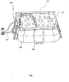
- FIGS. 1-6 provide an exemplary embodiment of a water sprayer outlet mechanism 100.
- water sprayer outlet mechanism 100 may be used to spray water into an above ground pool 101, as shown in FIG. 1 , or another suitable pool of water, such as an inflatable pool or a heated spa.
- the illustrative pool 101 includes a wall or liner 104, a plurality of vertical support structures or legs 105, and an upper annular support structure 103.
- the water sprayer outlet mechanism 100 may be partially or entirely concealed inside an outer cover (e.g., box) to provide a clean and modern appearance.
- the illustrative water sprayer outlet mechanism 100 is L-shaped and has an outlet or spray end 106 that faces vertically upward and an inlet end 108 that faces horizontally.
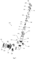
- Water sprayer outlet mechanism 100 includes a sprayer cover 110, a seal 120, an adjusting valve 130, a top cover 140, a power generating component 150, a light source 160 (e.g., LED), a lamp shade 170, an inlet pipe 180, and a connecting element 190.
- a light source 160 e.g., LED
- the illustrative sprayer cover 110 is fan-shaped and has a rectangular or ellipse-shaped outlet 112 that faces vertically upward toward outlet end 106 and a circular-shaped inlet 114 that faces vertically downward.
- Seal 120 which may be constructed of rubber or another suitable material, is rectangular or ellipse-shaped and is disposed at outlet 112 of sprayer cover 110.
- Top cover 140 is also disposed at outlet 112 of sprayer cover 110 and cooperates with sprayer cover 110, such as with bolts or other fasteners (not shown), to compress seal 120 therebetween.
- adjusting valve 130 is cylinder-shaped and defines an internal water spout passage 132 and an internal water curtain passage 134, which are located on opposing sides of lamp shade 170. As discussed further below, adjusting valve 130 is capable of being adjusted to deliver water from outlet end 106 via water spout passage 132, water curtain passage 134, or both, such that water flowing out of water spout passage 132 sprays out as a water spout, and water flowing out of water curtain passage 134 sprays out as a water curtain or sheet. More specifically, adjusting valve 130 is rotatably accommodated in sprayer cover 110 and cooperates with seal 120 to selectively plug and/or open outlet 112 of the sprayer cover 110.
- adjusting valve 130 further comprises a handle 136, which is disposed between water spout passage 132 and water curtain passage 134.
- Handle 136 extends outwardly from adjusting valve 130 and through top cover 140 and is used to manually rotate adjusting valve 130, so that seal 120 can toggle between engaging adjusting valve 130 at water spout passage 132, water curtain passage 134, or neither. More specifically, a user may manipulate handle 136 to rotate adjusting valve 130 so that seal 120 closes water spout passage 132 and opens water curtain passage 134, as shown in FIG. 5 , such that water only flows through water curtain passage 134.
- the user may manipulate handle 136 to rotate adjusting valve 130 so that seal 120 closes water curtain passage 134 and opens water spout passage 132, as shown in FIG. 6 , such that water only flows through water spout passage 134.
- the user may manipulate handle 136 to rotate adjusting valve 130 to a central position, such that water spout passage 132 and water curtain passage 134 are open at the same time, as shown in FIG. 4 .
- power generating component 150, light source 160, and lamp shade 170 may be disposed in sprayer cover 110.
- Lamp shade 170 may abut a lower end 138 of adjusting valve 130.
- Light source 160 is disposed in lamp shade 170, and power generating component 150 is operably connected to light source 160.
- water flowing through sprayer cover 110 impacts power generating component 150, so that power generating component 150 generates power and supplies power to light source 160.
- Lamp shade 170 may be at least partially translucent to allow light to pass from light source 160, through lamp shade 170, and into the water flowing through sprayer cover 110 so that illuminated water is sprayed from outlet end 106.
- Light source 160 may be configured to generate one or more colors of light.
- the power generating component 150 of water sprayer outlet mechanism 100 may have various features in common with the below-described power generating component 240 of water sprayer outlet mechanism 200.
- the illustrative power generating component 150 includes a deflecting cover 151, an impeller 152, a stator 153, a rotor 154, and a motor 156. Additional details regarding power generating component 150 are disclosed below with respect to power generating component 240.
- connecting element 190 is connected to an opening at the bottom inlet 114 of sprayer cover 110.
- the connecting element 190 is externally threaded and the sprayer cover 110 is internally threaded to form a threaded connection therebetween, but the type of connection may vary.
- a lower end 196 of connecting element 190 includes a hollow universal ball joint 192. Universal ball joint 192 is pivotally received within a tapered end or socket 181 of the inlet pipe 180 and captured therein by an interlocking retaining ring 182. This pivotal connection allows the user to control the direction of the outgoing water spray from outlet end 106 by moving connecting element 190 relative to inlet pipe 180.
- Inlet pipe 180 also includes an adapter 183 configured to connect water sprayer outlet mechanism 100 to a water source.
- the water source is a return hose 102 from pool 101, wherein the water is pumped and optionally filtered and/or heated before returning to pool 101 via return hose 102.
- Another interlocking retaining ring 184 may be provided to couple adapter 183 to inlet pipe 180.
- a nut 185 and a seal 186 may be provided to couple adapter 183 to pool 101.
- liner 104 of pool 101 is clamped and sealed between seal 186 on one side and outer face 187 of adapter 183 on the other side.
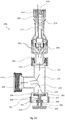
- the inlet pipe 180 is L-shaped, as shown in FIG. 4 , such that the inlet pipe 180 extends horizontally from the pool wall 104 and then vertically upward toward connecting element 190, sprayer cover 110, and other elements located near outlet end 106 of water sprayer outlet mechanism 100.
- FIGS. 7-18 provide another embodiment of a water sprayer outlet mechanism 200.
- the illustrative water sprayer outlet mechanism 200 is T-shaped and includes an inlet waterway 205 that extends horizontally from a water source (not shown), an outlet waterway 210 that extends vertically upward from the inlet waterway 205, and a decompression waterway 220 that extends vertically downward from the inlet waterway 205.
- decompression waterway 220 may open automatically to drain excess water and decompress the water pressure inside water sprayer outlet mechanism 200, thus stabilizing the water pressure of outlet waterway 210, so that outlet waterway 210 maintains an even flow rate.
- water sprayer outlet mechanism 200 may include a light source (e.g., LED) (not shown but similar to the above-described light source 160), an outlet or head component 230, and a power generating component 240 disposed in the water sprayer outlet mechanism 200 and operably connected to the light source (not shown).
- Power generating component 240 may be disposed in outlet component 230.
- water travels horizontally through inlet waterway 205 and vertically upward through outlet waterway 210 and outlet component 230. Then the water flowing through outlet component 230 impacts power generating component 240, so that power generating component 240 generates power and supplies power to the light source. The light passes from the light source and into the water, and then the illuminated water sprays out of outlet component 230.
- Outlet component 230 and power generating component 240 are described further below.
- water sprayer outlet mechanism 200 may include a T-shaped guiding pipe 270 comprising an inlet 272, an outlet 274, and a decompression or drainage port 276. As shown in FIG. 10 , the inlet 272 is disposed along inlet waterway 205, the outlet 274 is disposed along outlet waterway 210, and the decompression port 276 is disposed along decompression waterway 220.
- water sprayer outlet mechanism 200 may include an elastic element 250 (e.g., spring), a valve spool 260 used to open and close decompression waterway 220, a knob 280, a fixation nut 292, and a trimming nut 294.
- valve spool 260 is T-shaped and includes a sealing end cover 262 connected to a guiding column 264. Sealing end cover 262 is sleeved with a sealing pad 266, and valve spool 260 is aligned along the central axis of decompression port 276.
- Elastic element 250 is sleeved on the guiding column 264.
- Fixation nut 292 is connected to decompression port 276 of guiding pipe 270.
- Knob 280 is threaded and connected to fixation nut 292, such that a lower portion 282 of knob 280 abuts elastic element 250.
- Knob 280 further includes a hole 284 corresponding to guiding column 264. Trimming nut 294 is threaded and connected on lower portion 282 of knob 280 to abut elastic element 250.
- knob 280 By rotating knob 280, the user may move lower portion 282 of knob 280 upward to compress elastic element 250 or downward to release elastic element 250, such that elastic element 250 applies an adjustable force to valve spool 260 toward outlet waterway 210.
- elastic element 250 forces valve spool 260 upward to close decompression waterway 220, so water flows through outlet waterway 210 and out of water sprayer outlet mechanism 200.
- valve spool 260 When the water pressure in the outlet waterway 210 is above the user's preselected level, the water pressure on valve spool 260 is higher than the force applied to valve spool 260 by elastic element 250, so that the valve spool 260 and, more specifically, guiding column 264 is pushed downward into knob hole 284, thereby opening the decompression waterway 220.
- Water sprayer outlet mechanism 200 may have various features in common with the previously-described water sprayer outlet mechanism 100.
- water sprayer outlet mechanism 200 may include a connecting element 290 with a universal ball joint 292 for rotatably coupling outlet component 230 to guiding pipe 270.
- Outlet component 230 may include a sprayer cover 410, a seal 415, a lampshade 420 configured to receive the light source, and a guiding or deflecting plate 440.
- a top surface 422 of lampshade 420 is arc-shaped and includes an elongated outlet nozzle 460.
- Deflecting plate 440 cooperates with a side 424 of lampshade 420 to define a water spray passage 480.
- Water spray passage 480 has a tapered or conical shape with narrow top 482 and wide bottom 484. Top 482 of water spray passage 480 is connected to elongated outlet nozzle 460, such that water flows through water spray passage 480 and sprays out of elongated outlet nozzle 460 to form a water sheet of substantially even thickness.
- elongated outlet nozzle 460 may be bilaterally symmetrical about a central axis Y and have a width that is gradually larger from a center 462 to outer ends 469, so as to maintain a consistent thickness of an outlet water sheet.
- an elongated outlet nozzle not in accordance with the invention has an elongated, thin hole shape defined by a lateral straight line section 461, a lateral curved line section 462, a left end connecting line section 463, and a right end connecting line section 464 when projected or expanded in a horizontal plane.
- the lateral X-axis of the coordinate system tracks lateral straight line section 461
- the central Y-axis extends parallel to and between the left and right end connecting line sections 463 and 464, and the origin of the coordinate system is located at a midpoint 470 of lateral straight line section 461.
- a 0 1.5, 10 -7 ⁇ a 4 ⁇ 7 ⁇ 10 -10 , and 1.4 ⁇ 10 -3 ⁇ a 2 ⁇ 3 ⁇ 10 -4 .
- the system flow Q and the expected water sheet width H, which corresponds to the physical width of elongated outlet nozzle 460, are known.
- the expected water sheet width H which corresponds to the physical width of elongated outlet nozzle 460, is 120mm
- the water flow rate V is between 2 m/s
- the system volumetric flow rate Q is 550GPH in a certain lift
- an embodiment of the elongated outlet nozzle 460' is both bilaterally symmetrical about the central Y-axis and longitudinally symmetrical about the lateral X-axis.
- Elongated outlet nozzle 460' has an elongated, thin hole shape defined by an upper curve line section 465', a lower curve line section 466', a left end connecting line section 467', and a right end connecting line section 468' when projected or expanded in a horizontal plane.
- the X-axis of the coordinate system is located at a line of symmetry between upper curve line section 465' and lower curve line section 466', the origin of the coordinate system is located at a midpoint 471' between upper curve line section 465' and lower curve line section 466'.
- a 0 1.5, 5 ⁇ 10 -8 ⁇ a 4 ⁇ 3.5 ⁇ 10 -10 , and 7 ⁇ 10 -4 ⁇ a 2 ⁇ 1.5 ⁇ 10 -4
- a 0 1.5.
- a 4 4.5 ⁇ 10 -10
- a 2 2.5 ⁇ 10 -4 .
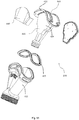
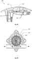
- Power generating component 240 may include an impeller 520, a stator 530, a rotor 540, an annular end cover 550, a motor 560, and a center shaft 570. Power generating component 240 may further include a deflecting cover 510 coupled to motor 560 and disposed such that an inlet passage 512 runs vertically through deflecting cover 510. Impeller 520 is rotatably disposed in inlet passage 512.
- An outer periphery surface 528 of impeller 520 includes a plurality of blades 522, which are adjacent to an outlet port 511 of inlet passage 512 and are inclined to the left with respect to an axis running parallel to inlet passage 512.
- a plurality of deflection plates 514 is evenly disposed in inlet passage 512 in the circumferential direction. Deflection plates 514 are adjacent to an inlet port 513 of inlet passage 512 and are inclined to the right with respect to an axis running parallel to inlet passage 512. Deflection plates 514 can change the water flow direction to make the water more directly impact blades 522. In the illustrated embodiment of FIG.
- an intersection angle ⁇ of blade 522 and an axis running parallel to inlet passage 512 is arranged at approximately 55-65 degrees, and an intersection angle ⁇ of deflection plate 514 and an axis running parallel to inlet passage 512 is arranged at approximately 25-45 degrees, which is less than angle ⁇ .
- the water that impacts deflection plate 514 may impact blade 522 at a substantially perpendicular angle, such as about 70-100 degrees.
- the thickness of blades 522 may be gradually larger from the upper end to the lower end 523.
- the thicker lower end 523 may have an arc-shaped surface that faces downward toward the deflection plate 514.
- the side of the deflecting cover 510 at the inlet port 513 of inlet passage 512 also includes a water diversion body 516.
- the exterior surface 515 of water diversion body 516 is a conical surface, such that water diffuses around diversion body 516 to impact the deflection plates 514 at a substantially perpendicular angle by the guiding of the water diversion body 516, and then diffuses around deflection plates 514 to impact blades 522 at a substantially perpendicular angle by the guiding of deflection plates 514.
- impeller 520 includes a stator cavity 524 and a rotor cavity 526.
- Rotor cavity 526 is annular-shaped and surrounds stator cavity 524.
- Stator 530 is located in stator cavity 524, and rotor 530 is located in rotor cavity 526.
- Annular end cap 550 is disposed to cover the rotor cavity 526.
- Motor 560 is inserted in stator cavity 524, and stator 530 is disposed in motor 560.
- Impeller 520 is disposed on center shaft 570, which is connected to deflecting cover 510 and motor 560.
- FIGS. 19-26 provide a further embodiment of a water sprayer outlet mechanism, specifically a water sheet sprayer outlet mechanism 300.
- water sheet sprayer outlet mechanism 300 may include a lower main body 301, an upper cover plate 302, an L-shaped water pipe 303, and a rectifying chamber 304.
- a front or outlet end 305 of main body 301 cooperates with cover plate 302 to form an elongated horizontal outlet 311.
- a rear or inlet end 306 of main body 301 is configured to receive water pipe 303, which includes inlet 312.
- cover plate 302 cooperates with cover plate 302 to define a hollow chamber 313, so as to connect inlet 312 and elongated outlet 311.
- Rectifying chamber 304 is disposed in the hollow chamber 313 and connected between inlet 312 and elongated outlet 311. Additionally, rectifying chamber 304 includes an upper cover 341 and a lower cover 342 that cooperate to define wavy sub-hollow chambers 340.
- Upper cover 341 includes at least a first protrusion 361, which may extend toward lower cover 342. In an exemplary embodiment, upper cover 341 also includes a third protrusion 362, although it may include more than the two protrusions 361, 362 shown in FIG. 20 .
- Lower cover 342 includes at least a second protrusion 371, which may extend toward upper cover 341, and is staggered between the first protrusion 361 and third protrusion 362. Like upper cover 341, lower cover 342 may include more than the one protrusion 371 shown in FIG. 20 .
- First protrusion 361, second protrusion 371, and third protrusion 362 cooperate to form wavy sub-hollow chambers 340.
- a front end 343 of lower cover 342 includes a vertical guard sheet or barrier 372, such that there is a clearance 373 between guard sheet 372 and upper cover 341.
- Clearance 373 is fluidly connected to wavy sub-hollow chambers 340 on one side and elongated outlet 311 on the other side with elongated outlet 311 at a lower position than clearance 373.
- the water exiting wavy sub-hollow chambers 340 travels upward, over guard sheet 372, and back downward to outlet 311.
- water is stabilized by the buffering and diffusing of the sub-hollow chambers 340 and guard sheet 372 and flows out of elongated outlet 311 evenly, thus forming a substantially flat water sheet instead of a column of water.
- the water output of the water sheet sprayer outlet mechanism 300 appears linear and attractive.
- water sheet sprayer outlet mechanism 300 may have other features in common with the previously-described water sprayer outlet mechanism 100 and/or water sprayer outlet mechanism 200.
- power generating component 314 is disposed between the inlet 312 and rectifying chamber 304, and light source 315 is disposed below elongated outlet 311.
- a first power generating component 314 includes an impeller 391, a stator 392 and a rotor 393.
- Stator 392 is assembled to a fixing rack 394 such that it is separated from the water flow, and rotor 393 is assembled to impeller 391.
- the water flow from inlet 312 impacts impeller 391 in the longitudinal direction to drive impeller 391 and rotate rotor 393, which generates voltage as the rotating magnetic field cuts the three-phase winding of stator 392.
- the voltage generated is then supplied to and powers light source 315 of FIG. 20 .
- an alternative power generating component 314' is disclosed in which water flow impacts impeller 391' in a tangential direction to drive impeller 391' to rotate rotor 393'. Because the water flow impacting impeller 391' in a tangential direction is slight, and in order to maintain a water sheet outlet effect, inlet 312 of water pipe 303 is connected to a diversion pipe 316' having two outlets 318', 320' to form two water flows ( FIG. 22 ). One water flow from outlet 318' enters the rectifying chamber 304 after impacting the impeller 391' in the tangential direction, and the other water flow from outlet 320' bypasses the impeller 391' and directly enters the rectifying chamber 304.
- water sheet sprayer outlet mechanism 300 may be connected to a support leg 317 or another component of pool 301, such as the liner or the upper annular support structure.
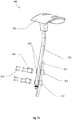
- support leg 317 has an upper fixing board or bracket 361 and a lower fixing board or bracket 362 each having a groove 365 that is configured to receive water pipe 321.
- Water pipe 321 is placed in grooves 365 and is fixed in grooves 365 via bolts 363 and clamping structures 364 that attach to brackets 361, 362.
Landscapes
- Engineering & Computer Science (AREA)
- Architecture (AREA)
- Civil Engineering (AREA)
- Structural Engineering (AREA)
- Life Sciences & Earth Sciences (AREA)
- Hydrology & Water Resources (AREA)
- Sustainable Development (AREA)
- Sustainable Energy (AREA)
- General Engineering & Computer Science (AREA)
- Nozzles (AREA)
Priority Applications (3)
| Application Number | Priority Date | Filing Date | Title |
|---|---|---|---|
| PL16777372T PL3157684T3 (pl) | 2015-04-08 | 2016-04-08 | Oświetlany spryskiwacz wody |
| EP19165961.4A EP3531008B1 (en) | 2015-04-08 | 2016-04-08 | Illuminated water sprayer |
| PL19165961T PL3531008T3 (pl) | 2015-04-08 | 2016-04-08 | Oświetlany spryskiwacz wody |
Applications Claiming Priority (6)
| Application Number | Priority Date | Filing Date | Title |
|---|---|---|---|
| CN201520205870.2U CN204552170U (zh) | 2015-04-08 | 2015-04-08 | 一种多功能出水机构 |
| CN201520207105.4U CN204553960U (zh) | 2015-04-08 | 2015-04-08 | 一种具有发光功能的出水装置 |
| CN201520310709.1U CN204620311U (zh) | 2015-05-14 | 2015-05-14 | 一种水帘出水机构和装配该出水机构的移动式水池 |
| CN201520618539.3U CN204866250U (zh) | 2015-08-17 | 2015-08-17 | 一种出水喷头 |
| CN201520618588.7U CN204877771U (zh) | 2015-08-17 | 2015-08-17 | 叶轮增速机构及使用该机构的水力发电装置 |
| PCT/US2016/026677 WO2016164747A1 (en) | 2015-04-08 | 2016-04-08 | Illuminated water sprayer |
Related Child Applications (2)
| Application Number | Title | Priority Date | Filing Date |
|---|---|---|---|
| EP19165961.4A Division-Into EP3531008B1 (en) | 2015-04-08 | 2016-04-08 | Illuminated water sprayer |
| EP19165961.4A Division EP3531008B1 (en) | 2015-04-08 | 2016-04-08 | Illuminated water sprayer |
Publications (3)
| Publication Number | Publication Date |
|---|---|
| EP3157684A1 EP3157684A1 (en) | 2017-04-26 |
| EP3157684A4 EP3157684A4 (en) | 2017-10-18 |
| EP3157684B1 true EP3157684B1 (en) | 2019-11-27 |
Family
ID=57072975
Family Applications (2)
| Application Number | Title | Priority Date | Filing Date |
|---|---|---|---|
| EP16777372.0A Active EP3157684B1 (en) | 2015-04-08 | 2016-04-08 | Illuminated water sprayer |
| EP19165961.4A Active EP3531008B1 (en) | 2015-04-08 | 2016-04-08 | Illuminated water sprayer |
Family Applications After (1)
| Application Number | Title | Priority Date | Filing Date |
|---|---|---|---|
| EP19165961.4A Active EP3531008B1 (en) | 2015-04-08 | 2016-04-08 | Illuminated water sprayer |
Country Status (4)
| Country | Link |
|---|---|
| US (1) | US10077571B2 (pl) |
| EP (2) | EP3157684B1 (pl) |
| PL (2) | PL3531008T3 (pl) |
| WO (1) | WO2016164747A1 (pl) |
Families Citing this family (11)
| Publication number | Priority date | Publication date | Assignee | Title |
|---|---|---|---|---|
| CN111836939B (zh) * | 2018-01-31 | 2022-06-07 | 上海荣威塑胶工业有限公司 | 用于泳池或水疗池的瀑布产生设备和系统 |
| DE102019111466B4 (de) * | 2019-05-03 | 2025-09-18 | Zumtobel Lighting Gmbh | Leuchte mit erweiterter Funktionalität |
| US11602032B2 (en) | 2019-12-20 | 2023-03-07 | Kohler Co. | Systems and methods for lighted showering |
| CN216949694U (zh) * | 2021-12-31 | 2022-07-12 | 上海荣威塑胶工业有限公司 | 喷水装置及地上水池 |
| USD982709S1 (en) * | 2022-07-11 | 2023-04-04 | Xiamen Tongbaohui Trading Co., Limited | Fountain |
| USD1006255S1 (en) * | 2023-02-21 | 2023-11-28 | Jiangsu Comco Outdoor Products Co., Ltd | Pool |
| CN222469528U (zh) * | 2024-05-27 | 2025-02-14 | 广州腾龙健康实业股份有限公司 | 一种自适应水速的光学水帘装置 |
| USD1069029S1 (en) * | 2024-11-07 | 2025-04-01 | Shenzhen Sipaiao Technology Co., Ltd. | Retractable pool fountain |
| USD1069975S1 (en) * | 2024-12-23 | 2025-04-08 | Jianqiang Yin | Pool fountain |
| USD1101897S1 (en) * | 2025-03-17 | 2025-11-11 | Xiaoxuan Su | Pool fountain |
| USD1083022S1 (en) * | 2025-03-17 | 2025-07-08 | Xiaoxuan Su | Pool fountain |
Family Cites Families (16)
| Publication number | Priority date | Publication date | Assignee | Title |
|---|---|---|---|---|
| US3503554A (en) * | 1968-09-09 | 1970-03-31 | Little Giant Corp | Fountain display apparatus |
| US3845291A (en) | 1974-02-08 | 1974-10-29 | Titan Tool And Die Co Inc | Water powered swimming pool light |
| DE3565171D1 (en) | 1984-05-09 | 1988-10-27 | Herman Paulus Maria Kessener | Liquid outlet adapted to provide lighting effects and/or for illumination |
| US4823409A (en) * | 1987-01-13 | 1989-04-25 | Kohler Co. | Sheet flow spout |
| US4920465A (en) * | 1988-11-15 | 1990-04-24 | Alopex Industries, Inc. | Floating fountain device |
| US5207499A (en) * | 1991-06-04 | 1993-05-04 | Kdi American Products, Inc. | Integral light and liquid circulation fitting |
| US6595675B2 (en) | 2001-04-23 | 2003-07-22 | Waterway Plastics, Inc. | Pool/spa waterfall unit with fiber optic illumination |
| US7698754B2 (en) * | 2004-04-01 | 2010-04-20 | Watkins Manufacturing Corporation | Ribbon flow waterfall for spas |
| US7200879B2 (en) * | 2004-07-27 | 2007-04-10 | Custom Molded Products Llc | Waterfall waterjet with debris removing outlet |
| US20060042689A1 (en) | 2004-09-01 | 2006-03-02 | Hinojosa Francisco Jr | Skimmer/waterfall with backlight |
| US7413319B2 (en) | 2006-03-31 | 2008-08-19 | Jose Longoria | Method and system for underwater light display |
| US8214935B2 (en) * | 2007-01-31 | 2012-07-10 | B & S Plastics, Inc. | Pop-up fountains |
| TWM331948U (en) * | 2007-08-07 | 2008-05-11 | kun-song Lv | Rotation and light-emitting structure of shower nozzle |
| GB0803251D0 (en) | 2008-02-22 | 2008-04-02 | Burnham Douglas P | A generator |
| CN201586580U (zh) | 2009-06-16 | 2010-09-22 | 曾广安 | 地坪式自动洒水器 |
| US20110290901A1 (en) | 2010-05-25 | 2011-12-01 | Dittman Iii Fred C | Fountain Faucet |
-
2016
- 2016-04-08 WO PCT/US2016/026677 patent/WO2016164747A1/en not_active Ceased
- 2016-04-08 EP EP16777372.0A patent/EP3157684B1/en active Active
- 2016-04-08 US US15/500,854 patent/US10077571B2/en active Active
- 2016-04-08 PL PL19165961T patent/PL3531008T3/pl unknown
- 2016-04-08 PL PL16777372T patent/PL3157684T3/pl unknown
- 2016-04-08 EP EP19165961.4A patent/EP3531008B1/en active Active
Non-Patent Citations (1)
| Title |
|---|
| None * |
Also Published As
| Publication number | Publication date |
|---|---|
| PL3157684T3 (pl) | 2020-05-18 |
| WO2016164747A1 (en) | 2016-10-13 |
| PL3531008T3 (pl) | 2021-10-04 |
| US10077571B2 (en) | 2018-09-18 |
| EP3157684A1 (en) | 2017-04-26 |
| US20170218648A1 (en) | 2017-08-03 |
| EP3157684A4 (en) | 2017-10-18 |
| EP3531008B1 (en) | 2021-03-31 |
| EP3531008A1 (en) | 2019-08-28 |
Similar Documents
| Publication | Publication Date | Title |
|---|---|---|
| EP3531008B1 (en) | Illuminated water sprayer | |
| US8458826B2 (en) | Washing device | |
| CN205056287U (zh) | 面盖旋转出水花洒 | |
| MXPA02010561A (es) | Mejoras en o relacionadas a una disposicion de boquilla. | |
| EP3751076B1 (en) | Water spraying device and pool | |
| KR20080006583U (ko) | 터보차저 방식의 샤워 헤드 | |
| CN1889998A (zh) | 具有一个垂直关闭阀的多用途手持喷洒器 | |
| WO2009050950A1 (ja) | 水中曝気装置 | |
| US20170225186A1 (en) | Energized fluid nozzles for splash pads | |
| CA2955104C (en) | Water spraying device for above ground pool | |
| CN1084422C (zh) | 逆流游泳池 | |
| US5388285A (en) | Swimming pool waterfall | |
| US20180297044A1 (en) | Multi-functional shower | |
| BR0209615A (pt) | Ejetor | |
| CN105169608B (zh) | 一种超远程消防水炮 | |
| CN103850295A (zh) | 淋浴用皂液分配器及给皂瓶 | |
| US8171576B2 (en) | Jetted bathtub | |
| US20030047327A1 (en) | Fire suppression apparatus with variable aeration mixing rate nozzle | |
| TWI459922B (zh) | Shower with soap dispenser and soap bottle | |
| JP2010029573A (ja) | シャワー装置 | |
| WO2006047381A3 (en) | Dry suction fitting assembly | |
| TWM449568U (zh) | 淋浴用皂液分配器及給皂瓶 | |
| CN211247123U (zh) | 旱喷二维摇摆喷泉装置 | |
| AU2011239348B2 (en) | Washing device | |
| CN206476066U (zh) | 一种出水口喷水调节器设备 |
Legal Events
| Date | Code | Title | Description |
|---|---|---|---|
| STAA | Information on the status of an ep patent application or granted ep patent |
Free format text: STATUS: THE INTERNATIONAL PUBLICATION HAS BEEN MADE |
|
| PUAI | Public reference made under article 153(3) epc to a published international application that has entered the european phase |
Free format text: ORIGINAL CODE: 0009012 |
|
| STAA | Information on the status of an ep patent application or granted ep patent |
Free format text: STATUS: REQUEST FOR EXAMINATION WAS MADE |
|
| 17P | Request for examination filed |
Effective date: 20170109 |
|
| AK | Designated contracting states |
Kind code of ref document: A1 Designated state(s): AL AT BE BG CH CY CZ DE DK EE ES FI FR GB GR HR HU IE IS IT LI LT LU LV MC MK MT NL NO PL PT RO RS SE SI SK SM TR |
|
| AX | Request for extension of the european patent |
Extension state: BA ME |
|
| A4 | Supplementary search report drawn up and despatched |
Effective date: 20170919 |
|
| RIC1 | Information provided on ipc code assigned before grant |
Ipc: E04H 4/14 20060101ALI20170913BHEP Ipc: F21W 131/401 20060101ALN20170913BHEP Ipc: F21W 121/02 20060101ALN20170913BHEP Ipc: B05B 1/04 20060101ALI20170913BHEP Ipc: B05B 17/08 20060101ALI20170913BHEP Ipc: B05B 15/06 20060101ALI20170913BHEP Ipc: B05B 1/16 20060101ALI20170913BHEP Ipc: F21S 9/04 20060101AFI20170913BHEP |
|
| DAV | Request for validation of the european patent (deleted) | ||
| DAX | Request for extension of the european patent (deleted) | ||
| GRAP | Despatch of communication of intention to grant a patent |
Free format text: ORIGINAL CODE: EPIDOSNIGR1 |
|
| STAA | Information on the status of an ep patent application or granted ep patent |
Free format text: STATUS: GRANT OF PATENT IS INTENDED |
|
| RIC1 | Information provided on ipc code assigned before grant |
Ipc: B05B 17/08 20060101ALI20180831BHEP Ipc: B05B 1/04 20060101ALI20180831BHEP Ipc: E04H 4/14 20060101ALI20180831BHEP Ipc: B05B 1/16 20060101ALI20180831BHEP Ipc: F21S 9/04 20060101AFI20180831BHEP Ipc: F21W 131/401 20060101ALN20180831BHEP Ipc: B05B 15/62 20180101ALI20180831BHEP Ipc: F21W 121/02 20060101ALN20180831BHEP |
|
| INTG | Intention to grant announced |
Effective date: 20181004 |
|
| GRAJ | Information related to disapproval of communication of intention to grant by the applicant or resumption of examination proceedings by the epo deleted |
Free format text: ORIGINAL CODE: EPIDOSDIGR1 |
|
| STAA | Information on the status of an ep patent application or granted ep patent |
Free format text: STATUS: REQUEST FOR EXAMINATION WAS MADE |
|
| GRAP | Despatch of communication of intention to grant a patent |
Free format text: ORIGINAL CODE: EPIDOSNIGR1 |
|
| STAA | Information on the status of an ep patent application or granted ep patent |
Free format text: STATUS: GRANT OF PATENT IS INTENDED |
|
| INTC | Intention to grant announced (deleted) | ||
| INTG | Intention to grant announced |
Effective date: 20190307 |
|
| RIC1 | Information provided on ipc code assigned before grant |
Ipc: B05B 17/08 20060101ALI20190225BHEP Ipc: E04H 4/14 20060101ALI20190225BHEP Ipc: B05B 1/16 20060101ALI20190225BHEP Ipc: F21S 9/04 20060101AFI20190225BHEP Ipc: B05B 15/62 20180101ALI20190225BHEP Ipc: F21W 131/401 20060101ALN20190225BHEP Ipc: F21W 121/02 20060101ALN20190225BHEP Ipc: B05B 1/04 20060101ALI20190225BHEP |
|
| GRAJ | Information related to disapproval of communication of intention to grant by the applicant or resumption of examination proceedings by the epo deleted |
Free format text: ORIGINAL CODE: EPIDOSDIGR1 |
|
| STAA | Information on the status of an ep patent application or granted ep patent |
Free format text: STATUS: REQUEST FOR EXAMINATION WAS MADE |
|
| REG | Reference to a national code |
Ref country code: DE Ref legal event code: R079 Ref document number: 602016025186 Country of ref document: DE Free format text: PREVIOUS MAIN CLASS: B05B0017080000 Ipc: F21S0009040000 |
|
| GRAP | Despatch of communication of intention to grant a patent |
Free format text: ORIGINAL CODE: EPIDOSNIGR1 |
|
| STAA | Information on the status of an ep patent application or granted ep patent |
Free format text: STATUS: GRANT OF PATENT IS INTENDED |
|
| INTC | Intention to grant announced (deleted) | ||
| RIC1 | Information provided on ipc code assigned before grant |
Ipc: E04H 4/14 20060101ALI20190613BHEP Ipc: F21W 121/02 20060101ALN20190613BHEP Ipc: B05B 1/04 20060101ALI20190613BHEP Ipc: B05B 17/08 20060101ALI20190613BHEP Ipc: B05B 1/16 20060101ALI20190613BHEP Ipc: B05B 15/62 20180101ALI20190613BHEP Ipc: F21S 9/04 20060101AFI20190613BHEP Ipc: F21W 131/401 20060101ALN20190613BHEP |
|
| INTG | Intention to grant announced |
Effective date: 20190625 |
|
| GRAS | Grant fee paid |
Free format text: ORIGINAL CODE: EPIDOSNIGR3 |
|
| GRAA | (expected) grant |
Free format text: ORIGINAL CODE: 0009210 |
|
| STAA | Information on the status of an ep patent application or granted ep patent |
Free format text: STATUS: THE PATENT HAS BEEN GRANTED |
|
| AK | Designated contracting states |
Kind code of ref document: B1 Designated state(s): AL AT BE BG CH CY CZ DE DK EE ES FI FR GB GR HR HU IE IS IT LI LT LU LV MC MK MT NL NO PL PT RO RS SE SI SK SM TR |
|
| REG | Reference to a national code |
Ref country code: GB Ref legal event code: FG4D |
|
| REG | Reference to a national code |
Ref country code: CH Ref legal event code: EP |
|
| REG | Reference to a national code |
Ref country code: AT Ref legal event code: REF Ref document number: 1207071 Country of ref document: AT Kind code of ref document: T Effective date: 20191215 |
|
| REG | Reference to a national code |
Ref country code: DE Ref legal event code: R096 Ref document number: 602016025186 Country of ref document: DE |
|
| REG | Reference to a national code |
Ref country code: IE Ref legal event code: FG4D |
|
| REG | Reference to a national code |
Ref country code: NL Ref legal event code: FP |
|
| REG | Reference to a national code |
Ref country code: LT Ref legal event code: MG4D |
|
| PG25 | Lapsed in a contracting state [announced via postgrant information from national office to epo] |
Ref country code: LV Free format text: LAPSE BECAUSE OF FAILURE TO SUBMIT A TRANSLATION OF THE DESCRIPTION OR TO PAY THE FEE WITHIN THE PRESCRIBED TIME-LIMIT Effective date: 20191127 Ref country code: SE Free format text: LAPSE BECAUSE OF FAILURE TO SUBMIT A TRANSLATION OF THE DESCRIPTION OR TO PAY THE FEE WITHIN THE PRESCRIBED TIME-LIMIT Effective date: 20191127 Ref country code: NO Free format text: LAPSE BECAUSE OF FAILURE TO SUBMIT A TRANSLATION OF THE DESCRIPTION OR TO PAY THE FEE WITHIN THE PRESCRIBED TIME-LIMIT Effective date: 20200227 Ref country code: FI Free format text: LAPSE BECAUSE OF FAILURE TO SUBMIT A TRANSLATION OF THE DESCRIPTION OR TO PAY THE FEE WITHIN THE PRESCRIBED TIME-LIMIT Effective date: 20191127 Ref country code: BG Free format text: LAPSE BECAUSE OF FAILURE TO SUBMIT A TRANSLATION OF THE DESCRIPTION OR TO PAY THE FEE WITHIN THE PRESCRIBED TIME-LIMIT Effective date: 20200227 Ref country code: GR Free format text: LAPSE BECAUSE OF FAILURE TO SUBMIT A TRANSLATION OF THE DESCRIPTION OR TO PAY THE FEE WITHIN THE PRESCRIBED TIME-LIMIT Effective date: 20200228 Ref country code: LT Free format text: LAPSE BECAUSE OF FAILURE TO SUBMIT A TRANSLATION OF THE DESCRIPTION OR TO PAY THE FEE WITHIN THE PRESCRIBED TIME-LIMIT Effective date: 20191127 |
|
| PG25 | Lapsed in a contracting state [announced via postgrant information from national office to epo] |
Ref country code: HR Free format text: LAPSE BECAUSE OF FAILURE TO SUBMIT A TRANSLATION OF THE DESCRIPTION OR TO PAY THE FEE WITHIN THE PRESCRIBED TIME-LIMIT Effective date: 20191127 Ref country code: IS Free format text: LAPSE BECAUSE OF FAILURE TO SUBMIT A TRANSLATION OF THE DESCRIPTION OR TO PAY THE FEE WITHIN THE PRESCRIBED TIME-LIMIT Effective date: 20200327 Ref country code: RS Free format text: LAPSE BECAUSE OF FAILURE TO SUBMIT A TRANSLATION OF THE DESCRIPTION OR TO PAY THE FEE WITHIN THE PRESCRIBED TIME-LIMIT Effective date: 20191127 |
|
| PG25 | Lapsed in a contracting state [announced via postgrant information from national office to epo] |
Ref country code: AL Free format text: LAPSE BECAUSE OF FAILURE TO SUBMIT A TRANSLATION OF THE DESCRIPTION OR TO PAY THE FEE WITHIN THE PRESCRIBED TIME-LIMIT Effective date: 20191127 |
|
| PG25 | Lapsed in a contracting state [announced via postgrant information from national office to epo] |
Ref country code: CZ Free format text: LAPSE BECAUSE OF FAILURE TO SUBMIT A TRANSLATION OF THE DESCRIPTION OR TO PAY THE FEE WITHIN THE PRESCRIBED TIME-LIMIT Effective date: 20191127 Ref country code: RO Free format text: LAPSE BECAUSE OF FAILURE TO SUBMIT A TRANSLATION OF THE DESCRIPTION OR TO PAY THE FEE WITHIN THE PRESCRIBED TIME-LIMIT Effective date: 20191127 Ref country code: PT Free format text: LAPSE BECAUSE OF FAILURE TO SUBMIT A TRANSLATION OF THE DESCRIPTION OR TO PAY THE FEE WITHIN THE PRESCRIBED TIME-LIMIT Effective date: 20200419 Ref country code: EE Free format text: LAPSE BECAUSE OF FAILURE TO SUBMIT A TRANSLATION OF THE DESCRIPTION OR TO PAY THE FEE WITHIN THE PRESCRIBED TIME-LIMIT Effective date: 20191127 Ref country code: DK Free format text: LAPSE BECAUSE OF FAILURE TO SUBMIT A TRANSLATION OF THE DESCRIPTION OR TO PAY THE FEE WITHIN THE PRESCRIBED TIME-LIMIT Effective date: 20191127 Ref country code: ES Free format text: LAPSE BECAUSE OF FAILURE TO SUBMIT A TRANSLATION OF THE DESCRIPTION OR TO PAY THE FEE WITHIN THE PRESCRIBED TIME-LIMIT Effective date: 20191127 |
|
| REG | Reference to a national code |
Ref country code: DE Ref legal event code: R097 Ref document number: 602016025186 Country of ref document: DE |
|
| PG25 | Lapsed in a contracting state [announced via postgrant information from national office to epo] |
Ref country code: SK Free format text: LAPSE BECAUSE OF FAILURE TO SUBMIT A TRANSLATION OF THE DESCRIPTION OR TO PAY THE FEE WITHIN THE PRESCRIBED TIME-LIMIT Effective date: 20191127 Ref country code: SM Free format text: LAPSE BECAUSE OF FAILURE TO SUBMIT A TRANSLATION OF THE DESCRIPTION OR TO PAY THE FEE WITHIN THE PRESCRIBED TIME-LIMIT Effective date: 20191127 |
|
| REG | Reference to a national code |
Ref country code: AT Ref legal event code: MK05 Ref document number: 1207071 Country of ref document: AT Kind code of ref document: T Effective date: 20191127 |
|
| PLBE | No opposition filed within time limit |
Free format text: ORIGINAL CODE: 0009261 |
|
| STAA | Information on the status of an ep patent application or granted ep patent |
Free format text: STATUS: NO OPPOSITION FILED WITHIN TIME LIMIT |
|
| 26N | No opposition filed |
Effective date: 20200828 |
|
| PG25 | Lapsed in a contracting state [announced via postgrant information from national office to epo] |
Ref country code: MC Free format text: LAPSE BECAUSE OF FAILURE TO SUBMIT A TRANSLATION OF THE DESCRIPTION OR TO PAY THE FEE WITHIN THE PRESCRIBED TIME-LIMIT Effective date: 20191127 Ref country code: AT Free format text: LAPSE BECAUSE OF FAILURE TO SUBMIT A TRANSLATION OF THE DESCRIPTION OR TO PAY THE FEE WITHIN THE PRESCRIBED TIME-LIMIT Effective date: 20191127 Ref country code: SI Free format text: LAPSE BECAUSE OF FAILURE TO SUBMIT A TRANSLATION OF THE DESCRIPTION OR TO PAY THE FEE WITHIN THE PRESCRIBED TIME-LIMIT Effective date: 20191127 |
|
| REG | Reference to a national code |
Ref country code: CH Ref legal event code: PL |
|
| PG25 | Lapsed in a contracting state [announced via postgrant information from national office to epo] |
Ref country code: LI Free format text: LAPSE BECAUSE OF NON-PAYMENT OF DUE FEES Effective date: 20200430 Ref country code: CH Free format text: LAPSE BECAUSE OF NON-PAYMENT OF DUE FEES Effective date: 20200430 Ref country code: LU Free format text: LAPSE BECAUSE OF NON-PAYMENT OF DUE FEES Effective date: 20200408 |
|
| REG | Reference to a national code |
Ref country code: BE Ref legal event code: MM Effective date: 20200430 |
|
| PG25 | Lapsed in a contracting state [announced via postgrant information from national office to epo] |
Ref country code: BE Free format text: LAPSE BECAUSE OF NON-PAYMENT OF DUE FEES Effective date: 20200430 |
|
| PG25 | Lapsed in a contracting state [announced via postgrant information from national office to epo] |
Ref country code: IE Free format text: LAPSE BECAUSE OF NON-PAYMENT OF DUE FEES Effective date: 20200408 |
|
| PG25 | Lapsed in a contracting state [announced via postgrant information from national office to epo] |
Ref country code: TR Free format text: LAPSE BECAUSE OF FAILURE TO SUBMIT A TRANSLATION OF THE DESCRIPTION OR TO PAY THE FEE WITHIN THE PRESCRIBED TIME-LIMIT Effective date: 20191127 Ref country code: MT Free format text: LAPSE BECAUSE OF FAILURE TO SUBMIT A TRANSLATION OF THE DESCRIPTION OR TO PAY THE FEE WITHIN THE PRESCRIBED TIME-LIMIT Effective date: 20191127 Ref country code: CY Free format text: LAPSE BECAUSE OF FAILURE TO SUBMIT A TRANSLATION OF THE DESCRIPTION OR TO PAY THE FEE WITHIN THE PRESCRIBED TIME-LIMIT Effective date: 20191127 |
|
| PG25 | Lapsed in a contracting state [announced via postgrant information from national office to epo] |
Ref country code: MK Free format text: LAPSE BECAUSE OF FAILURE TO SUBMIT A TRANSLATION OF THE DESCRIPTION OR TO PAY THE FEE WITHIN THE PRESCRIBED TIME-LIMIT Effective date: 20191127 |
|
| P01 | Opt-out of the competence of the unified patent court (upc) registered |
Effective date: 20230524 |
|
| PGFP | Annual fee paid to national office [announced via postgrant information from national office to epo] |
Ref country code: DE Payment date: 20250214 Year of fee payment: 10 |
|
| PGFP | Annual fee paid to national office [announced via postgrant information from national office to epo] |
Ref country code: NL Payment date: 20260213 Year of fee payment: 11 |
|
| PGFP | Annual fee paid to national office [announced via postgrant information from national office to epo] |
Ref country code: GB Payment date: 20260216 Year of fee payment: 11 |
|
| PGFP | Annual fee paid to national office [announced via postgrant information from national office to epo] |
Ref country code: IT Payment date: 20260320 Year of fee payment: 11 |
|
| PGFP | Annual fee paid to national office [announced via postgrant information from national office to epo] |
Ref country code: FR Payment date: 20260209 Year of fee payment: 11 |
|
| PGFP | Annual fee paid to national office [announced via postgrant information from national office to epo] |
Ref country code: PL Payment date: 20260216 Year of fee payment: 11 |