EP3157449B1 - Vis pédiculaire avec outil de vissage - Google Patents
Vis pédiculaire avec outil de vissage Download PDFInfo
- Publication number
- EP3157449B1 EP3157449B1 EP15728847.3A EP15728847A EP3157449B1 EP 3157449 B1 EP3157449 B1 EP 3157449B1 EP 15728847 A EP15728847 A EP 15728847A EP 3157449 B1 EP3157449 B1 EP 3157449B1
- Authority
- EP
- European Patent Office
- Prior art keywords
- thread
- screw
- bone screw
- lead
- region
- Prior art date
- Legal status (The legal status is an assumption and is not a legal conclusion. Google has not performed a legal analysis and makes no representation as to the accuracy of the status listed.)
- Active
Links
- 210000000988 bone and bone Anatomy 0.000 claims description 38
- 241000722921 Tulipa gesneriana Species 0.000 claims description 13
- 238000003801 milling Methods 0.000 claims description 4
- 238000004519 manufacturing process Methods 0.000 claims description 2
- 230000002093 peripheral effect Effects 0.000 claims 2
- 230000003313 weakening effect Effects 0.000 description 3
- 230000006641 stabilisation Effects 0.000 description 2
- 238000011105 stabilization Methods 0.000 description 2
- 230000015572 biosynthetic process Effects 0.000 description 1
- 230000008878 coupling Effects 0.000 description 1
- 238000010168 coupling process Methods 0.000 description 1
- 238000005859 coupling reaction Methods 0.000 description 1
- 239000000463 material Substances 0.000 description 1
- 238000005457 optimization Methods 0.000 description 1
- 239000007858 starting material Substances 0.000 description 1
- 238000001356 surgical procedure Methods 0.000 description 1
- 230000007704 transition Effects 0.000 description 1
Images
Classifications
-
- A—HUMAN NECESSITIES
- A61—MEDICAL OR VETERINARY SCIENCE; HYGIENE
- A61B—DIAGNOSIS; SURGERY; IDENTIFICATION
- A61B17/00—Surgical instruments, devices or methods, e.g. tourniquets
- A61B17/56—Surgical instruments or methods for treatment of bones or joints; Devices specially adapted therefor
- A61B17/58—Surgical instruments or methods for treatment of bones or joints; Devices specially adapted therefor for osteosynthesis, e.g. bone plates, screws, setting implements or the like
- A61B17/68—Internal fixation devices, including fasteners and spinal fixators, even if a part thereof projects from the skin
- A61B17/70—Spinal positioners or stabilisers ; Bone stabilisers comprising fluid filler in an implant
- A61B17/7001—Screws or hooks combined with longitudinal elements which do not contact vertebrae
- A61B17/7032—Screws or hooks with U-shaped head or back through which longitudinal rods pass
-
- A—HUMAN NECESSITIES
- A61—MEDICAL OR VETERINARY SCIENCE; HYGIENE
- A61B—DIAGNOSIS; SURGERY; IDENTIFICATION
- A61B17/00—Surgical instruments, devices or methods, e.g. tourniquets
- A61B17/56—Surgical instruments or methods for treatment of bones or joints; Devices specially adapted therefor
- A61B17/58—Surgical instruments or methods for treatment of bones or joints; Devices specially adapted therefor for osteosynthesis, e.g. bone plates, screws, setting implements or the like
- A61B17/68—Internal fixation devices, including fasteners and spinal fixators, even if a part thereof projects from the skin
- A61B17/84—Fasteners therefor or fasteners being internal fixation devices
- A61B17/86—Pins or screws or threaded wires; nuts therefor
- A61B17/866—Material or manufacture
-
- A—HUMAN NECESSITIES
- A61—MEDICAL OR VETERINARY SCIENCE; HYGIENE
- A61B—DIAGNOSIS; SURGERY; IDENTIFICATION
- A61B17/00—Surgical instruments, devices or methods, e.g. tourniquets
- A61B17/56—Surgical instruments or methods for treatment of bones or joints; Devices specially adapted therefor
- A61B17/58—Surgical instruments or methods for treatment of bones or joints; Devices specially adapted therefor for osteosynthesis, e.g. bone plates, screws, setting implements or the like
- A61B17/68—Internal fixation devices, including fasteners and spinal fixators, even if a part thereof projects from the skin
- A61B17/84—Fasteners therefor or fasteners being internal fixation devices
- A61B17/86—Pins or screws or threaded wires; nuts therefor
- A61B17/8665—Nuts
-
- F—MECHANICAL ENGINEERING; LIGHTING; HEATING; WEAPONS; BLASTING
- F16—ENGINEERING ELEMENTS AND UNITS; GENERAL MEASURES FOR PRODUCING AND MAINTAINING EFFECTIVE FUNCTIONING OF MACHINES OR INSTALLATIONS; THERMAL INSULATION IN GENERAL
- F16B—DEVICES FOR FASTENING OR SECURING CONSTRUCTIONAL ELEMENTS OR MACHINE PARTS TOGETHER, e.g. NAILS, BOLTS, CIRCLIPS, CLAMPS, CLIPS OR WEDGES; JOINTS OR JOINTING
- F16B35/00—Screw-bolts; Stay-bolts; Screw-threaded studs; Screws; Set screws
- F16B35/04—Screw-bolts; Stay-bolts; Screw-threaded studs; Screws; Set screws with specially-shaped head or shaft in order to fix the bolt on or in an object
- F16B35/041—Specially-shaped shafts
- F16B35/044—Specially-shaped ends
- F16B35/047—Specially-shaped ends for preventing cross-threading, i.e. preventing skewing of bolt and nut
Definitions
- the present invention relates to a bone screw system, in particular a pedicle screw system, comprising a bone screw or a pedicle screw, a receiving sleeve and a clamping screw that can be screwed into this, the receiving sleeve having a sleeve wall that accommodates a longitudinal support for the surgically connecting adjacent bone or pedicle screws is formed and provided with an internal thread, wherein the clamping screw is provided with an external thread and can be screwed into the internal thread of the receiving sleeve.
- Bone and pedicle screws are known from the prior art. They are used, for example, for dorsal stabilization of the spine by means of transpedicular screw connections.
- pedicle screws are placed in the pedicles of adjacent vertebrae, whereupon an angularly stable connection is created between the pedicle screws arranged axially one above the other and an axially extending longitudinal member or bar.
- the pedicle screws and longitudinal beams form a vertebral stabilization system.
- a pedicle screw usually has a screw shaft running in the axial direction with an external thread, to which a receiving sleeve, the so-called tulip, is connected on the screw head side.
- This is essentially U-shaped with opposing wall sections and a gap formed between them and running in the radial direction for the longitudinal member or web.
- An internal thread running in the axial direction is introduced into the tulip.
- the longitudinal beam is inserted in the radial direction into the gap in the tulip and fixed by means of a locking element or a clamping screw, usually in the form of a grub screw or threaded nut, which is also referred to as a set screw and is screwed into the internal thread.
- US 2011/0152947 A1 shows a pedicle screw with a receiving sleeve, the flanks of which have an internal thread, the uppermost thread of which has been partially removed.
- Tilting can lead to the thread cut, especially that of the setscrew, being damaged.
- so-called “crossthreading” can occur, which means that the setscrew is tilted so far to the longitudinal axis of the screw shaft and its external thread that the thread start of the setscrew, i.e. the inlet thread or threads, engages or extends into the wrong thread of the inner thread of the tulip intervene, which can damage the thread or even render the set screw and / or the pedicle screw unusable.
- the prior art pedicle screw systems described above are disadvantageously cost-intensive and complex. As a rule, they are not in a position to facilitate the correct placement of a set screw on a pedicle screw or to ensure that it is reliable.
- a screwdriver with a guide sleeve can only prevent tilting to a limited extent, as this guide sleeve requires a certain amount of play for coupling.
- this sleeve restricts the doctor's view of the bone or pedicle screw.
- An optimization of the gate improves the finding of the thread, however, despite this measure it can lead to tilting.
- a tilting of a "cut" setscrew is critical because it can be damaged very easily due to the thinner wall thickness.
- the invention is based on the object of providing a bone screw system, in particular a pedicle screw system, which makes it easier and safer to correctly place a set screw on a bone or pedicle screw without the need for additional elements such as guide sleeves etc. are necessary or the surgeon's view is restricted.
- a bone screw system or pedicle screw system according to the preamble of claim 1, wherein a thread of the internal thread has a widened inlet section on the inlet side, the expansion of which is formed in the axial direction as well as in the radial direction.
- the present description is made with reference to a bone screw system or a bone screw.
- the invention relates in particular to a pedicle screw system or a pedicle screw.
- the term bone screw is therefore to be understood as directed towards a pedicle screw and vice versa.
- the inlet section is widened compared to the rest of the usual course of the thread.
- the internal thread of the receiving sleeve as well as the external thread of the clamping screw can be designed as a single or multiple thread. In the case of multi-start threads, it is particularly advantageous if each thread turn has a widened inlet section and is widened on the inlet side.
- the widened inlet section advantageously ensures that the cross-sectional window available for engagement with an inlet thread web of the clamping screw is enlarged compared to screw systems according to the prior art. Even if the clamping screw is positioned at an angle on the receiving sleeve, that is to say if it is positioned with non-aligned axes, the external thread and internal thread cannot "seize”. Rather, the external thread of the clamping screw can penetrate into the internal thread without damaging contact with a thread flank of the internal thread. Depending on the size of the widening, it is possible for the clamping screw to tilt in relation to the receiving sleeve with a more or less deviating alignment of the axes of the clamping screw and the receiving sleeve.
- a particular advantage of the invention is that as the screwing depth into the internal thread increases, the clamping screw aligns itself relative to the receiving sleeve. This alignment is done in advantageously automatically and until the axes of the clamping screw and receiving sleeve are aligned and the clamping screw is straight and correctly seated in the internal thread. It is therefore no longer necessary for a surgeon to pay particular attention to the straightforward application of the set crew, which makes things considerably easier and saves time.
- the widened thread entry or thread start forms a kind of ramp, so to speak, in order to guide or lift a clamping screw or setscrew that is initially set at an angle or tilted when being applied into the actual thread turn and the clamping screw or setscrew is again coaxial with the internal thread of the receiving sleeve align.
- the inlet section is widened in the axial direction. Such a widening acts in a particularly effective way against tilting or tilting of the clamping screw with respect to the axis of the receiving sleeve.
- the widening of the inlet section is formed in the radial direction, which results in a particularly simple positioning of the clamping screw in the radial direction relative to the receiving sleeve. This is particularly advantageous in operations with a very limited view.
- the inlet section has a flank. This can be inclined in the circumferential direction with respect to the flank in the further course of the remaining thread turn, that is to say outside the inlet section. It can have a lower inclination than the rest of the thread turn, but can also increase in particular into the internal thread. It is preferably the flank of the inlet section facing the thread root. The slope of the flank is preferably flatter in the case of the flank pointing towards the thread root, and preferably steeper in the case of the flank pointing towards the thread inlet than the slope of the flank in the further course of the rest of the thread.
- both flanks of the inlet section that is to say the flank pointing towards the thread root and the flank pointing towards the thread inlet, are designed in the aforementioned form with a different inclination. In this way, the inlet window can be made very large.
- the cross section of the thread turn in particular the cross section in the radial direction, at the thread inlet can be 1.7 to 1.2 times, preferably 1.6 to 1.3 times and particularly preferably 1.5 times. times to 1.4 times the cross-section of the thread outside the inlet section.
- the thickness in the axial direction of a thread ridge located between the inlet section and an adjacent thread turn can be reduced by less than 50%, preferably by less than 35% and particularly preferably by less than 20%, compared to the thickness of a thread ridge between adjacent threads.
- the inlet section can extend into the internal thread to different extents in the circumferential direction. It is preferred if the inlet section extends in the circumferential direction over a radial section between approx. 20 ° and approx. 135 °, preferably between approx. 40 ° and approx. 115 °, more preferably between approx. 60 ° and approx. 90 ° . In this way, the final alignment of the clamping screw only takes place when it has been screwed sufficiently far into the internal thread for a required hold in the internal thread, so that repeated tilting or loosening of the clamping screw can be reliably avoided.
- the internal thread of the receiving sleeve and / or the external thread of the clamping screw is an undercut thread, in particular an undercut buttress thread.
- the thread can also have a T-shaped or L-shaped cross section.
- the screw system according to the invention can be a monoaxial or a polyaxial system.
- the receiving sleeve can be designed in one piece with the bone screw or that the receiving sleeve can be positioned as a separate element, in particular can be arranged on the bone screw so that it can be positioned at an angle.
- the receiving sleeve is firmly connected to its shaft, for example made in one piece, welded or soldered.
- this can have an externally threaded section manufactured as a separate shaft component with a spherical or (semi) spherical screw head.
- the receiving sleeve can be arranged on this in an angularly positionable manner.
- the receiving sleeve can grip behind the screw head in the transition area to the bone screw shaft.
- the receiving sleeve can be pivoted and / or rotated relative to the shaft in order to obtain a desired position and orientation essentially independently of the orientation of the shaft.
- the undercut prevents the receiving sleeve from being pulled off the shaft head.
- the receiving sleeve can then be fixed in position on the screw head of the bone screw by means of the clamping screw with the longitudinal beam / web in intermediate position or by means of an additional screw element.
- the above-mentioned object is also achieved by a method for producing a bone screw system according to the invention, in particular a bone screw system according to one of the appended claims, the widening in the inlet section being formed by milling, in particular by milling the widening into the already formed thread, preferably by means of a T-slot cutter.
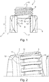
- Fig. 1 shows the head area of a pedicle screw system 1 in a side view.
- the pedicle screw system 1 has a pedicle screw 2, a receiving sleeve 3 and a clamping screw 4.
- the receiving sleeve 3 can in principle be designed in one piece with the pedicle screw 2 as a so-called tulip or as a separate component.
- the latter can be movably arranged on the pedicle screw 2, so that a polyaxial Pedicle screw system is formed in which the receiving sleeve 3 can be angularly positioned relative to the pedicle screw 2.
- the following description is made with reference to a receiving sleeve 3 formed in one piece with the pedicle screw 2, but can also be read in relation to a polyaxial pedicle screw system.
- the pedicle screw 2 is provided on the side opposite the receiving sleeve 3 with an external thread, not shown in the figures, with which it can be screwed into a pedicle canal of a vertebra (as an example of a bone).
- the pedicle screw 2 is provided with a screw tool engagement (not shown in the figures).
- the receiving sleeve 3 has an essentially U-shaped shape with a hole 6 made therein in the axial direction and having an internal thread 5.
- the receiving sleeve 3 can be formed by removing material from a hollow cylinder on radially opposite sides in the axial direction and providing the hole of the hollow cylinder with the internal thread 5.
- Two radially opposite sleeve wall sections 7, 8 remain of the hollow cylinder, the inner surfaces of which, facing one another, delimit the hole 6 and are provided with the internal thread 5.
- the clamping screw 4 is provided in the form of a grub screw customary for this purpose with an external thread 9 and an end-face tool holder (not shown in the figures), for example an internal hexagon recess.
- Fig. 2 shows the internal thread 5 of a pedicle screw system 1 according to the prior art.
- the internal thread 5 is designed to be catchy. It has a single thread with a first thread section 10 in the first sleeve wall section 7, a second thread section 11 in the opposite sleeve wall section 8, a third thread section 12 in the first sleeve wall section 7, a fourth thread section 13 in turn in the opposite sleeve wall section 8, etc.
- the thread sections 10, 12 in the first sleeve wall section 7 have a Inlet side 14 and an outlet side 15.
- the thread sections 11, 13 in the second sleeve wall section 8 also have an inlet side and an outlet side.
- FIG. 1 shows the clamping screw 4 at the beginning of the screwing into the receiving sleeve 3. It can be clearly seen that the clamping screw 4 for correct screwing of its external thread 9 into the internal thread 5 is to be aligned relative to the receiving sleeve 3 in such a way that the axis 16 of the clamping screw 4 with the axis 17 of the internal thread 5 covered. Fig. 1 shows such positioning. It is easy to see that such a positioning can be very problematic, particularly with polygonal pedicle screws and / or with restricted visibility and / or poor accessibility.
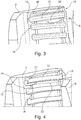
- the Figures 3 and 4 show an inlet section 18, designed according to the invention, of the internal thread 5 of the receiving sleeve 3 in two different embodiments.
- the inlet section 18 extends over the entire circumferential length of the first thread section 10.
- the cross section of the thread section 10 in the axial direction is a conventional one Way formed first thread portion 10 (see e.g. Fig. 1 ) is widened.
- the remaining thread sections 11, 12, 13 etc. have a constant cross section in a conventional manner.
- the widened inlet section 18 advantageously means that the cross-sectional window available for engagement with an inlet thread web 19 of the clamping screw 4 is enlarged compared to the prior art. Even in the case of a tilted attachment of the clamping screw 4 to the receiving sleeve 3, that is, if it is attached with misaligned axes 16, 17, the external thread 9 and internal thread 5, in particular the inlet thread web 19 and flank 21 of the, cannot "seize" first thread section 10 come.
- the inlet thread web 19 can without damaging contact with a thread flank of the first Thread section 10 penetrate into this from the inlet side 14, depending on the size of the expansion with more or less deviating alignment of the axes 16, 17 the axes 16, 17 are finally aligned and the clamping screw can be screwed straight and correctly into the internal thread 5.
- Fig. 4 shows a slightly different embodiment of the widened inlet section 18.
- the inlet section 18 extends less far in the circumferential direction into the first thread section 10.
- the expansion in the axial direction is smaller than in the embodiment of FIG Fig. 3 .
- the thread of the internal thread 5 is designed with an L-shaped cross section.
Landscapes
- Health & Medical Sciences (AREA)
- Orthopedic Medicine & Surgery (AREA)
- Life Sciences & Earth Sciences (AREA)
- Surgery (AREA)
- Engineering & Computer Science (AREA)
- Neurology (AREA)
- Nuclear Medicine, Radiotherapy & Molecular Imaging (AREA)
- Biomedical Technology (AREA)
- Heart & Thoracic Surgery (AREA)
- Medical Informatics (AREA)
- Molecular Biology (AREA)
- Animal Behavior & Ethology (AREA)
- General Health & Medical Sciences (AREA)
- Public Health (AREA)
- Veterinary Medicine (AREA)
- General Engineering & Computer Science (AREA)
- Mechanical Engineering (AREA)
- Surgical Instruments (AREA)
Claims (10)
- Vis à os (2), en particulier vis pédiculaire, avec une douille de réception ou tulipe (3) prévue au niveau de la tête de vis qui présente deux flancs de douille (7, 8) pourvus d'un filet intérieur (5), entre lesquels un logement pour un longeron est réalisé pour la liaison chirurgicale de vis à os contigües (2), dans laquelle un pas de filet (10) du filet intérieur (5) au moins d'un flanc de douille (7, 8) présente côté entrée de filet une section d'entrée (18) élargie,
caractérisée en ce que
l'élargissement de la section d'entrée (18) est réalisé dans le sens axial ainsi que dans le sens radial. - Vis à os (2) selon la revendication 1, caractérisée en ce que la section d'entrée (18) est élargie dans le sens axial vers la tête de vis.
- Vis à os (2) selon la revendication 1 ou 2, caractérisée en ce que la section d'entrée (18) présente un flanc (21) qui est incliné par rapport au flanc (22) dans la suite de l'étendue du pas de filet (10, 11, 12, 13) restant dans le sens périphérique, en particulier monte dans le filet intérieur (5).
- Vis à os (2) selon la revendication 3, caractérisée en ce que l'inclinaison du flanc (21) de la section d'entrée de filet (18) est plus plate que l'inclinaison du flanc (22) dans la suite de l'étendue du pas de filet (10, 11, 12, 13) restant, dans laquelle l'inclinaison correspond de préférence à 0,5 fois à 0,9 fois, de manière davantage préférée à 0,6 fois à 0,8 fois et de manière particulièrement préférée à 0,7 fois l'inclinaison dans la suite de l'étendue restante du pas de filet (10, 11, 12, 13).
- Vis à os (2) selon l'une des revendications précédentes, caractérisée en ce que la section transversale (dans le sens radial) du pas de filet (10) au niveau de l'entrée de filet (14) s'élève à 1,7 fois à 1,2 fois, de préférence à 1,6 fois à 1,3 fois et de manière particulièrement préférée à 1,5 fois à 1,4 fois la section transversale du pas de filet (10, 11, 12, 13) en dehors de la section d'entrée (18).
- Vis à os (2) selon l'une des revendications précédentes, caractérisée en ce que la section d'entrée (18) s'étend dans le sens périphérique sur une section radiale entre environ 20° et environ 135 °, de préférence entre environ 40° et environ 115 °, de manière davantage préférée entre environ 60° et environ 90°.
- Vis à os (2) selon l'une des revendications précédentes, caractérisée en ce que le filet intérieur (5) est un filet de contre-dépouille, en particulier un filet en dent de scie contre-dépouillé ou le pas de filet (10, 11, 12, 13) présente une section transversale en forme de T ou de L.
- Vis à os (2) selon l'une des revendications précédentes, caractérisée en ce que l'épaisseur dans le sens axial d'une nervure de filet (20) se trouvant entre la section d'entrée (18) et un pas de filet (12) contigu par rapport à l'épaisseur d'une nervure de pas (20) entre des pas de filet (10, 11, 12, 13) contigus est réduite de moins de 50 %, de préférence de moins de 35 % et de manière particulièrement préférée de moins de 20%.
- Vis à os (2) selon l'une des revendications précédentes, caractérisée en ce que la douille de réception (3) est réalisée d'un seul tenant avec la vis à os ou la douille de réception (3) est agencée de manière positionnable comme élément séparé, en particulier de manière positionnable en angle par rapport à la vis à os (2) au niveau de celle-ci.
- Procédé de fabrication d'une vis à os (2) selon l'une des revendications précédentes, caractérisé en ce que l'élargissement est réalisé dans la section d'entrée (18) par fraisage, en particulier en ce que l'élargissement est fraisé dans le pas de filet (10) déjà réalisé, de préférence au moyen d'une fraiseuse à rainure en T.
Applications Claiming Priority (2)
| Application Number | Priority Date | Filing Date | Title |
|---|---|---|---|
| DE102014108705.4A DE102014108705A1 (de) | 2014-06-20 | 2014-06-20 | Pedikelschraube mit Einschraubhilfe |
| PCT/EP2015/063140 WO2015193178A1 (fr) | 2014-06-20 | 2015-06-12 | Vis pédiculaire avec outil de vissage |
Publications (2)
| Publication Number | Publication Date |
|---|---|
| EP3157449A1 EP3157449A1 (fr) | 2017-04-26 |
| EP3157449B1 true EP3157449B1 (fr) | 2021-08-18 |
Family
ID=53396495
Family Applications (1)
| Application Number | Title | Priority Date | Filing Date |
|---|---|---|---|
| EP15728847.3A Active EP3157449B1 (fr) | 2014-06-20 | 2015-06-12 | Vis pédiculaire avec outil de vissage |
Country Status (5)
| Country | Link |
|---|---|
| US (1) | US10758275B2 (fr) |
| EP (1) | EP3157449B1 (fr) |
| DE (1) | DE102014108705A1 (fr) |
| ES (1) | ES2894230T3 (fr) |
| WO (1) | WO2015193178A1 (fr) |
Families Citing this family (1)
| Publication number | Priority date | Publication date | Assignee | Title |
|---|---|---|---|---|
| DE102015109481A1 (de) * | 2015-06-15 | 2016-12-15 | Aesculap Ag | Pedikelschraube mit radial versetzter Führung |
Citations (4)
| Publication number | Priority date | Publication date | Assignee | Title |
|---|---|---|---|---|
| US20090318970A1 (en) * | 2008-06-19 | 2009-12-24 | Butler Michael S | Spinal Rod Connectors Configured to Retain Spinal Rods of Varying Diameters |
| WO2012103660A1 (fr) * | 2011-02-04 | 2012-08-09 | Spinesave Ag | Mesure prise pour pallier les risques de dévers induisant des blocages au niveau de vis d'ostéosynthèse ouvertes |
| US20120310290A1 (en) * | 2005-02-22 | 2012-12-06 | Jackson Roger P | Polyaxial bone screw with spherical capture, compression insert and alignment and retention structures |
| US20130079830A1 (en) * | 2004-04-20 | 2013-03-28 | Laszlo Garamszegi | Pedicle screw assembly |
Family Cites Families (12)
| Publication number | Priority date | Publication date | Assignee | Title |
|---|---|---|---|---|
| DE19912364B4 (de) * | 1999-03-19 | 2004-10-07 | Peter Brehm | Pedikelschraube |
| US20060083603A1 (en) * | 2000-08-23 | 2006-04-20 | Jackson Roger P | Reverse angled threadform with anti-splay clearance |
| US6726689B2 (en) * | 2002-09-06 | 2004-04-27 | Roger P. Jackson | Helical interlocking mating guide and advancement structure |
| SE518461C2 (sv) | 2001-02-21 | 2002-10-15 | Henrik Hansson | Benskruv, sätt för att framställa dess gängor och borr för att borra hål för detsamma |
| US20030171755A1 (en) * | 2002-03-05 | 2003-09-11 | Moseley Colin F. | Bone screws |
| US6817816B2 (en) * | 2002-08-13 | 2004-11-16 | Nd Industries, Inc. | Tapping assist fastening element and method |
| US8876868B2 (en) * | 2002-09-06 | 2014-11-04 | Roger P. Jackson | Helical guide and advancement flange with radially loaded lip |
| US7214227B2 (en) * | 2004-03-22 | 2007-05-08 | Innovative Spinal Technologies | Closure member for a medical implant device |
| DE202005007495U1 (de) * | 2005-05-04 | 2005-08-11 | Aesculap Ag & Co. Kg | Orthopädisches Verankerungselement und Osteosynthesevorrichtung |
| EP2410191B1 (fr) * | 2009-03-16 | 2015-10-21 | Aoyama Seisakusho Co., Ltd. | Composant de vis femelle et composant de fixation l'utilisant |
| US8801761B2 (en) * | 2009-12-18 | 2014-08-12 | X-Spine Systems, Inc. | Spinal implant locking member with improved guidance, tactile and visual feedback |
| US10058354B2 (en) * | 2013-01-28 | 2018-08-28 | Roger P. Jackson | Pivotal bone anchor assembly with frictional shank head seating surfaces |
-
2014
- 2014-06-20 DE DE102014108705.4A patent/DE102014108705A1/de not_active Withdrawn
-
2015
- 2015-06-12 EP EP15728847.3A patent/EP3157449B1/fr active Active
- 2015-06-12 ES ES15728847T patent/ES2894230T3/es active Active
- 2015-06-12 US US15/318,549 patent/US10758275B2/en active Active
- 2015-06-12 WO PCT/EP2015/063140 patent/WO2015193178A1/fr active Application Filing
Patent Citations (4)
| Publication number | Priority date | Publication date | Assignee | Title |
|---|---|---|---|---|
| US20130079830A1 (en) * | 2004-04-20 | 2013-03-28 | Laszlo Garamszegi | Pedicle screw assembly |
| US20120310290A1 (en) * | 2005-02-22 | 2012-12-06 | Jackson Roger P | Polyaxial bone screw with spherical capture, compression insert and alignment and retention structures |
| US20090318970A1 (en) * | 2008-06-19 | 2009-12-24 | Butler Michael S | Spinal Rod Connectors Configured to Retain Spinal Rods of Varying Diameters |
| WO2012103660A1 (fr) * | 2011-02-04 | 2012-08-09 | Spinesave Ag | Mesure prise pour pallier les risques de dévers induisant des blocages au niveau de vis d'ostéosynthèse ouvertes |
Also Published As
| Publication number | Publication date |
|---|---|
| US10758275B2 (en) | 2020-09-01 |
| WO2015193178A1 (fr) | 2015-12-23 |
| DE102014108705A1 (de) | 2015-12-24 |
| US20170128103A1 (en) | 2017-05-11 |
| EP3157449A1 (fr) | 2017-04-26 |
| ES2894230T3 (es) | 2022-02-14 |
Similar Documents
| Publication | Publication Date | Title |
|---|---|---|
| EP3288475B1 (fr) | Vis pédiculaire présentant un filetage à os de grand diamètre | |
| DE102005021879B4 (de) | Orthopädisches Verankerungselement und Osteosynthesevorrichtung | |
| EP0053999B1 (fr) | Dispositif d'ostéosynthèse et calibre de perçage approprié | |
| EP3117787B1 (fr) | Vis pediculaire avec tulipe | |
| EP2892451B1 (fr) | Implant de la ceinture pelvienne | |
| EP1457161B1 (fr) | Dispositif de fixation pour l'utilisation dans la chirurgie de la colonne vertebrale ou de l'os et méthode de la fabrication | |
| DE19534136B4 (de) | Externer oder interner Fixateur zur Wiederherstellung des Skeletts bei Brüchen oder Arthroplastiken | |
| WO2004032774A1 (fr) | Element d'ancrage d'os | |
| DE102016108504A1 (de) | Medizintechnisches Instrument zur provisorischen Fixierung einer polyaxialen Pedikelschraube | |
| WO2004086990A1 (fr) | Logement pour un element de blocage et element de blocage | |
| EP2844169B1 (fr) | Système à plaque osseuse pour l'ostéosynthèse | |
| DE102016002444A1 (de) | Osteosynthesevorrichtung mit einer Knochenplatte sowie mit wenigstens einer Knochenschraube | |
| EP3081180A1 (fr) | Systeme de fixation pour os | |
| DE202005007495U1 (de) | Orthopädisches Verankerungselement und Osteosynthesevorrichtung | |
| EP3031416A1 (fr) | Dispositif d'osteosynthese | |
| EP3157449B1 (fr) | Vis pédiculaire avec outil de vissage | |
| EP3005962A1 (fr) | Douille de securite pour une vis pediculaire | |
| CH716094B1 (de) | Winkelversetzte Schraubeneingriffnahme. | |
| EP3487430B1 (fr) | Système de vis pédiculaire muni d'une vis de verrouillage comprenant une partie filetée | |
| EP2801330B1 (fr) | Plaque d'ostéosynthèse dotée d'un inlay et procédé de fabrication de la plaque d'ostéosynthèse | |
| DE102015109481A1 (de) | Pedikelschraube mit radial versetzter Führung | |
| DE102014108225A1 (de) | Feststellschraube und chirurgisches Schraubensystem | |
| WO2008003313A2 (fr) | Système de fixation ostéosynthétique | |
| DE102013107170A1 (de) | Knochenschraube | |
| EP2842504B1 (fr) | Vis à os, plaque implantable et système formé des deux |
Legal Events
| Date | Code | Title | Description |
|---|---|---|---|
| STAA | Information on the status of an ep patent application or granted ep patent |
Free format text: STATUS: THE INTERNATIONAL PUBLICATION HAS BEEN MADE |
|
| PUAI | Public reference made under article 153(3) epc to a published international application that has entered the european phase |
Free format text: ORIGINAL CODE: 0009012 |
|
| STAA | Information on the status of an ep patent application or granted ep patent |
Free format text: STATUS: REQUEST FOR EXAMINATION WAS MADE |
|
| 17P | Request for examination filed |
Effective date: 20170111 |
|
| AK | Designated contracting states |
Kind code of ref document: A1 Designated state(s): AL AT BE BG CH CY CZ DE DK EE ES FI FR GB GR HR HU IE IS IT LI LT LU LV MC MK MT NL NO PL PT RO RS SE SI SK SM TR |
|
| AX | Request for extension of the european patent |
Extension state: BA ME |
|
| DAV | Request for validation of the european patent (deleted) | ||
| DAX | Request for extension of the european patent (deleted) | ||
| STAA | Information on the status of an ep patent application or granted ep patent |
Free format text: STATUS: EXAMINATION IS IN PROGRESS |
|
| 17Q | First examination report despatched |
Effective date: 20190409 |
|
| STAA | Information on the status of an ep patent application or granted ep patent |
Free format text: STATUS: EXAMINATION IS IN PROGRESS |
|
| GRAP | Despatch of communication of intention to grant a patent |
Free format text: ORIGINAL CODE: EPIDOSNIGR1 |
|
| STAA | Information on the status of an ep patent application or granted ep patent |
Free format text: STATUS: GRANT OF PATENT IS INTENDED |
|
| INTG | Intention to grant announced |
Effective date: 20210311 |
|
| GRAS | Grant fee paid |
Free format text: ORIGINAL CODE: EPIDOSNIGR3 |
|
| GRAA | (expected) grant |
Free format text: ORIGINAL CODE: 0009210 |
|
| STAA | Information on the status of an ep patent application or granted ep patent |
Free format text: STATUS: THE PATENT HAS BEEN GRANTED |
|
| AK | Designated contracting states |
Kind code of ref document: B1 Designated state(s): AL AT BE BG CH CY CZ DE DK EE ES FI FR GB GR HR HU IE IS IT LI LT LU LV MC MK MT NL NO PL PT RO RS SE SI SK SM TR |
|
| REG | Reference to a national code |
Ref country code: GB Ref legal event code: FG4D Free format text: NOT ENGLISH |
|
| REG | Reference to a national code |
Ref country code: CH Ref legal event code: EP |
|
| REG | Reference to a national code |
Ref country code: DE Ref legal event code: R096 Ref document number: 502015015073 Country of ref document: DE |
|
| REG | Reference to a national code |
Ref country code: IE Ref legal event code: FG4D Free format text: LANGUAGE OF EP DOCUMENT: GERMAN Ref country code: AT Ref legal event code: REF Ref document number: 1420920 Country of ref document: AT Kind code of ref document: T Effective date: 20210915 |
|
| REG | Reference to a national code |
Ref country code: LT Ref legal event code: MG9D |
|
| REG | Reference to a national code |
Ref country code: NL Ref legal event code: MP Effective date: 20210818 |
|
| PG25 | Lapsed in a contracting state [announced via postgrant information from national office to epo] |
Ref country code: LT Free format text: LAPSE BECAUSE OF FAILURE TO SUBMIT A TRANSLATION OF THE DESCRIPTION OR TO PAY THE FEE WITHIN THE PRESCRIBED TIME-LIMIT Effective date: 20210818 Ref country code: BG Free format text: LAPSE BECAUSE OF FAILURE TO SUBMIT A TRANSLATION OF THE DESCRIPTION OR TO PAY THE FEE WITHIN THE PRESCRIBED TIME-LIMIT Effective date: 20211118 Ref country code: PT Free format text: LAPSE BECAUSE OF FAILURE TO SUBMIT A TRANSLATION OF THE DESCRIPTION OR TO PAY THE FEE WITHIN THE PRESCRIBED TIME-LIMIT Effective date: 20211220 Ref country code: NO Free format text: LAPSE BECAUSE OF FAILURE TO SUBMIT A TRANSLATION OF THE DESCRIPTION OR TO PAY THE FEE WITHIN THE PRESCRIBED TIME-LIMIT Effective date: 20211118 Ref country code: FI Free format text: LAPSE BECAUSE OF FAILURE TO SUBMIT A TRANSLATION OF THE DESCRIPTION OR TO PAY THE FEE WITHIN THE PRESCRIBED TIME-LIMIT Effective date: 20210818 Ref country code: SE Free format text: LAPSE BECAUSE OF FAILURE TO SUBMIT A TRANSLATION OF THE DESCRIPTION OR TO PAY THE FEE WITHIN THE PRESCRIBED TIME-LIMIT Effective date: 20210818 Ref country code: RS Free format text: LAPSE BECAUSE OF FAILURE TO SUBMIT A TRANSLATION OF THE DESCRIPTION OR TO PAY THE FEE WITHIN THE PRESCRIBED TIME-LIMIT Effective date: 20210818 Ref country code: HR Free format text: LAPSE BECAUSE OF FAILURE TO SUBMIT A TRANSLATION OF THE DESCRIPTION OR TO PAY THE FEE WITHIN THE PRESCRIBED TIME-LIMIT Effective date: 20210818 |
|
| REG | Reference to a national code |
Ref country code: ES Ref legal event code: FG2A Ref document number: 2894230 Country of ref document: ES Kind code of ref document: T3 Effective date: 20220214 |
|
| PG25 | Lapsed in a contracting state [announced via postgrant information from national office to epo] |
Ref country code: PL Free format text: LAPSE BECAUSE OF FAILURE TO SUBMIT A TRANSLATION OF THE DESCRIPTION OR TO PAY THE FEE WITHIN THE PRESCRIBED TIME-LIMIT Effective date: 20210818 Ref country code: LV Free format text: LAPSE BECAUSE OF FAILURE TO SUBMIT A TRANSLATION OF THE DESCRIPTION OR TO PAY THE FEE WITHIN THE PRESCRIBED TIME-LIMIT Effective date: 20210818 Ref country code: GR Free format text: LAPSE BECAUSE OF FAILURE TO SUBMIT A TRANSLATION OF THE DESCRIPTION OR TO PAY THE FEE WITHIN THE PRESCRIBED TIME-LIMIT Effective date: 20211119 |
|
| PG25 | Lapsed in a contracting state [announced via postgrant information from national office to epo] |
Ref country code: NL Free format text: LAPSE BECAUSE OF FAILURE TO SUBMIT A TRANSLATION OF THE DESCRIPTION OR TO PAY THE FEE WITHIN THE PRESCRIBED TIME-LIMIT Effective date: 20210818 |
|
| PG25 | Lapsed in a contracting state [announced via postgrant information from national office to epo] |
Ref country code: DK Free format text: LAPSE BECAUSE OF FAILURE TO SUBMIT A TRANSLATION OF THE DESCRIPTION OR TO PAY THE FEE WITHIN THE PRESCRIBED TIME-LIMIT Effective date: 20210818 |
|
| REG | Reference to a national code |
Ref country code: DE Ref legal event code: R097 Ref document number: 502015015073 Country of ref document: DE |
|
| PG25 | Lapsed in a contracting state [announced via postgrant information from national office to epo] |
Ref country code: SM Free format text: LAPSE BECAUSE OF FAILURE TO SUBMIT A TRANSLATION OF THE DESCRIPTION OR TO PAY THE FEE WITHIN THE PRESCRIBED TIME-LIMIT Effective date: 20210818 Ref country code: SK Free format text: LAPSE BECAUSE OF FAILURE TO SUBMIT A TRANSLATION OF THE DESCRIPTION OR TO PAY THE FEE WITHIN THE PRESCRIBED TIME-LIMIT Effective date: 20210818 Ref country code: RO Free format text: LAPSE BECAUSE OF FAILURE TO SUBMIT A TRANSLATION OF THE DESCRIPTION OR TO PAY THE FEE WITHIN THE PRESCRIBED TIME-LIMIT Effective date: 20210818 Ref country code: EE Free format text: LAPSE BECAUSE OF FAILURE TO SUBMIT A TRANSLATION OF THE DESCRIPTION OR TO PAY THE FEE WITHIN THE PRESCRIBED TIME-LIMIT Effective date: 20210818 Ref country code: CZ Free format text: LAPSE BECAUSE OF FAILURE TO SUBMIT A TRANSLATION OF THE DESCRIPTION OR TO PAY THE FEE WITHIN THE PRESCRIBED TIME-LIMIT Effective date: 20210818 Ref country code: AL Free format text: LAPSE BECAUSE OF FAILURE TO SUBMIT A TRANSLATION OF THE DESCRIPTION OR TO PAY THE FEE WITHIN THE PRESCRIBED TIME-LIMIT Effective date: 20210818 |
|
| PLBE | No opposition filed within time limit |
Free format text: ORIGINAL CODE: 0009261 |
|
| STAA | Information on the status of an ep patent application or granted ep patent |
Free format text: STATUS: NO OPPOSITION FILED WITHIN TIME LIMIT |
|
| 26N | No opposition filed |
Effective date: 20220519 |
|
| PG25 | Lapsed in a contracting state [announced via postgrant information from national office to epo] |
Ref country code: IT Free format text: LAPSE BECAUSE OF FAILURE TO SUBMIT A TRANSLATION OF THE DESCRIPTION OR TO PAY THE FEE WITHIN THE PRESCRIBED TIME-LIMIT Effective date: 20210818 |
|
| PG25 | Lapsed in a contracting state [announced via postgrant information from national office to epo] |
Ref country code: SI Free format text: LAPSE BECAUSE OF FAILURE TO SUBMIT A TRANSLATION OF THE DESCRIPTION OR TO PAY THE FEE WITHIN THE PRESCRIBED TIME-LIMIT Effective date: 20210818 |
|
| PG25 | Lapsed in a contracting state [announced via postgrant information from national office to epo] |
Ref country code: MC Free format text: LAPSE BECAUSE OF FAILURE TO SUBMIT A TRANSLATION OF THE DESCRIPTION OR TO PAY THE FEE WITHIN THE PRESCRIBED TIME-LIMIT Effective date: 20210818 |
|
| REG | Reference to a national code |
Ref country code: BE Ref legal event code: MM Effective date: 20220630 |
|
| PG25 | Lapsed in a contracting state [announced via postgrant information from national office to epo] |
Ref country code: LU Free format text: LAPSE BECAUSE OF NON-PAYMENT OF DUE FEES Effective date: 20220612 Ref country code: IE Free format text: LAPSE BECAUSE OF NON-PAYMENT OF DUE FEES Effective date: 20220612 |
|
| PG25 | Lapsed in a contracting state [announced via postgrant information from national office to epo] |
Ref country code: BE Free format text: LAPSE BECAUSE OF NON-PAYMENT OF DUE FEES Effective date: 20220630 |
|
| PGFP | Annual fee paid to national office [announced via postgrant information from national office to epo] |
Ref country code: FR Payment date: 20230621 Year of fee payment: 9 Ref country code: DE Payment date: 20230620 Year of fee payment: 9 |
|
| REG | Reference to a national code |
Ref country code: AT Ref legal event code: MM01 Ref document number: 1420920 Country of ref document: AT Kind code of ref document: T Effective date: 20220612 |
|
| P01 | Opt-out of the competence of the unified patent court (upc) registered |
Effective date: 20230731 |
|
| PG25 | Lapsed in a contracting state [announced via postgrant information from national office to epo] |
Ref country code: AT Free format text: LAPSE BECAUSE OF NON-PAYMENT OF DUE FEES Effective date: 20220612 |
|
| PGFP | Annual fee paid to national office [announced via postgrant information from national office to epo] |
Ref country code: GB Payment date: 20230622 Year of fee payment: 9 Ref country code: ES Payment date: 20230719 Year of fee payment: 9 Ref country code: CH Payment date: 20230702 Year of fee payment: 9 |
|
| PG25 | Lapsed in a contracting state [announced via postgrant information from national office to epo] |
Ref country code: HU Free format text: LAPSE BECAUSE OF FAILURE TO SUBMIT A TRANSLATION OF THE DESCRIPTION OR TO PAY THE FEE WITHIN THE PRESCRIBED TIME-LIMIT; INVALID AB INITIO Effective date: 20150612 |
|
| PG25 | Lapsed in a contracting state [announced via postgrant information from national office to epo] |
Ref country code: MK Free format text: LAPSE BECAUSE OF FAILURE TO SUBMIT A TRANSLATION OF THE DESCRIPTION OR TO PAY THE FEE WITHIN THE PRESCRIBED TIME-LIMIT Effective date: 20210818 Ref country code: CY Free format text: LAPSE BECAUSE OF FAILURE TO SUBMIT A TRANSLATION OF THE DESCRIPTION OR TO PAY THE FEE WITHIN THE PRESCRIBED TIME-LIMIT Effective date: 20210818 |