EP3157165A1 - Method for determining a temperature of a rotor - Google Patents
Method for determining a temperature of a rotor Download PDFInfo
- Publication number
- EP3157165A1 EP3157165A1 EP16191366.0A EP16191366A EP3157165A1 EP 3157165 A1 EP3157165 A1 EP 3157165A1 EP 16191366 A EP16191366 A EP 16191366A EP 3157165 A1 EP3157165 A1 EP 3157165A1
- Authority
- EP
- European Patent Office
- Prior art keywords
- rotor
- stator
- electric machine
- inductance
- value
- Prior art date
- Legal status (The legal status is an assumption and is not a legal conclusion. Google has not performed a legal analysis and makes no representation as to the accuracy of the status listed.)
- Ceased
Links
Images
Classifications
-
- H—ELECTRICITY
- H02—GENERATION; CONVERSION OR DISTRIBUTION OF ELECTRIC POWER
- H02P—CONTROL OR REGULATION OF ELECTRIC MOTORS, ELECTRIC GENERATORS OR DYNAMO-ELECTRIC CONVERTERS; CONTROLLING TRANSFORMERS, REACTORS OR CHOKE COILS
- H02P29/00—Arrangements for regulating or controlling electric motors, appropriate for both AC and DC motors
- H02P29/60—Controlling or determining the temperature of the motor or of the drive
- H02P29/66—Controlling or determining the temperature of the rotor
-
- G—PHYSICS
- G01—MEASURING; TESTING
- G01R—MEASURING ELECTRIC VARIABLES; MEASURING MAGNETIC VARIABLES
- G01R31/00—Arrangements for testing electric properties; Arrangements for locating electric faults; Arrangements for electrical testing characterised by what is being tested not provided for elsewhere
- G01R31/34—Testing dynamo-electric machines
- G01R31/343—Testing dynamo-electric machines in operation
-
- H—ELECTRICITY
- H02—GENERATION; CONVERSION OR DISTRIBUTION OF ELECTRIC POWER
- H02P—CONTROL OR REGULATION OF ELECTRIC MOTORS, ELECTRIC GENERATORS OR DYNAMO-ELECTRIC CONVERTERS; CONTROLLING TRANSFORMERS, REACTORS OR CHOKE COILS
- H02P21/00—Arrangements or methods for the control of electric machines by vector control, e.g. by control of field orientation
- H02P21/14—Estimation or adaptation of machine parameters, e.g. flux, current or voltage
-
- H—ELECTRICITY
- H02—GENERATION; CONVERSION OR DISTRIBUTION OF ELECTRIC POWER
- H02P—CONTROL OR REGULATION OF ELECTRIC MOTORS, ELECTRIC GENERATORS OR DYNAMO-ELECTRIC CONVERTERS; CONTROLLING TRANSFORMERS, REACTORS OR CHOKE COILS
- H02P23/00—Arrangements or methods for the control of AC motors characterised by a control method other than vector control
- H02P23/14—Estimation or adaptation of motor parameters, e.g. rotor time constant, flux, speed, current or voltage
Definitions
- the invention relates to a method and a device for determining a temperature of a rotor of an electric machine.
- An electric machine which can be used as a generator and / or as a motor, comprises as components a fixed stator and a rotor rotating relative to the stator. To operate the electric machine, among other things, it is necessary to currently record their operating parameters. However, since the rotor can rotate relatively quickly during operation of the electric machine, it is usually not possible to directly detect some operating parameters of the rotor, for example by measurement.
- a method for operating a separately excited synchronous machine is known from the document DE 10 2010 014 173 A1 known.
- a flow of a rotor of the synchronous machine is determined with a model and from this an excitation current is determined.
- An electronically commutated asynchronous motor in the publication DE 10 2008 018 843 A1 includes a sensor for determining a position of a rotor, wherein based on a detected position, a temperature in the asynchronous motor is to characterize.
- EP 2 120 329 A2 It is described to estimate a temperature of a rotor of an induction motor based on various quantities resulting from an operation of the induction motor.
- the method according to the invention is designed to determine a temperature T R of a rotor of an electric machine, which is rotatable relative to a stator of the electric machine.
- the operating parameters of the electric machine applied to the stator voltage U S a current flowing through the stator I S , a rotational frequency ⁇ R of the rotor, a rotating field frequency ⁇ S of the stator, an inductance L R of the rotor, an inductance L S of the stator and a main inductance L H of the electric machine determined.
- a current value of the temperature T R of the rotor is determined as a function of the electrical resistance R R as the operating parameter of the rotor.
- inductance L of the rotor R Values of inductance L of the rotor R, the inductance L S of the stator and the main inductance L H of the electric machine according to specifications, for example. A table or a characteristic curve, specified and recorded.
- the specification is provided in an embodiment based on the values determined in the test bench.
- .DELTA.R ⁇ R R . Ref .DELTA.T
- R R , Ref is a reference value for the resistor R R and T R
- Ref is a reference value for the temperature T R of the rotor, these reference values being correlated with one another and, for example, also being determined in the test bench.
- T R , Ref 20 ° C. is the reference value of the temperature T R at which the reference value R R , Ref of the resistance results due to material properties of the rotor.
- the current value of the temperature T R is determined by the current value of the resistor R R in relation to T R , Ref and R R, Ref .
- the mutually associated reference values T R , Ref and R R , Ref for temperature and resistance are also determined in the test rig in an embodiment.
- T R R R - R R . Ref ⁇ R R . Ref + T R . Ref calculated.
- ⁇ is a coefficient dependent on the material of the rotor
- R R , Ref is the reference value of the electrical resistance R R of the rotor
- T R Ref is the reference value of the temperature T R of the rotor.
- the rotor has the reference value R R , Ref of the electrical resistance R R , when the rotor has the reference value T R , Ref the temperature T R and vice versa.
- the device according to the invention is designed to determine a temperature T R of a rotor of an electric machine, which is rotatable relative to a stator of the electric machine, and comprises at least one measuring device, at least one detection device and a control device.
- the at least one measuring device is designed to measure, as operating parameter of the electric machine, a voltage U S applied to the stator, a current I S flowing through the stator, a rotational frequency ⁇ R of the rotor and a rotational field frequency ⁇ S of the stator, and thus to determine it.
- the at least one detection device is designed to determine an inductance L S of the stator, an inductance L R of the rotor and a main inductance L H of the electric machine.
- a first measuring device is embodied as a voltage measuring device assigned to the stator and / or to be assigned, which is designed to measure at least one value of the voltage U S applied to the stator.
- a second measuring device is embodied as a measuring device assigned to and / or associated with the stator and designed to detect at least one value of the current I S flowing through the stator.
- a third measuring device is embodied as a rotational frequency measuring device or rotational speed measuring device assigned to and / or associated with the rotor, which is designed to determine at least one value of the rotational frequency ⁇ R of the rotor.
- a fourth measuring device is embodied as a rotating field frequency measuring device assigned to the stator and / or to be assigned, which is designed to measure at least one value of the rotating field frequency ⁇ S of the stator.
- values of electrical and mechanical operating parameters of at least one component i. H. measured and / or detected the stator and / or the rotor of the electric machine.
- the control unit usually comprises a computing unit and a memory unit. Values of inductance L R of the rotor, the inductance L S of the stator and the main inductance I H of the electric machine, according to a default, for example. From a table or curve to detect, with this requirement, which can be provided as a table or characteristic in the storage unit is stored.
- the device also comprises a test stand having a plurality of detection devices, wherein a first detection device associated with the rotor and / or assigned and adapted to detect at least one value of the inductance L R of the rotor, wherein a second detection device associated with the stator and / or is assigned and designed to determine at least one value of the inductance L S of the stator, wherein a third detection device associated with the electric machine and / or assigned and is designed to determine at least one value of the main inductance L H of the electric machine.
- the rotor rotates as the first component of the electric machine during operation of the electric machine relative to the stator as the second component of the electric machine.
- one of the two components usually the rotor, on permanent magnets, which generate a permanent magnetic field.
- the other of the two components usually the stator, in contrast, has several coils.
- the electric machine is to operate as a motor and / or as a generator. When operated as a motor, electrical current is passed through the coils, thus inducing a magnetic field that interacts with the permanent magnetic field. In this way it is possible to convert electrical energy into mechanical energy, usually rotational energy, with the electric machine. If the electric machine is alternatively or additionally operated as a generator, the rotor is mechanically rotated, wherein a current is induced in the coils and thus mechanical energy is converted into electrical energy.
- the temperature of the electric machine designed, for example, as an asynchronous machine is indirectly determined via the electrical resistance of the rotor to be determined.
- a temperature sensor or a To arrange thermometer it is possible, by means of a temperature model, which is stored as a default in the control unit or a converter of the electric machine to determine the value of the temperature from the detected current value of the resistance of the rotor, taking into account a dependence of the temperature of the resistor.
- it is provided for determining the temperature of the rotor to also take into account values of a load profile of the electric machine and / or a temperature of the stator.
- the temperature of the rotor at a start of the electric machine is calculated rather than merely estimated.
- the method is also feasible if the temperature of the rotor after a restart of the electric machine should be unknown. Thus, it is not necessary to know which temperature the rotor has exhibited, for example, when switching off the electric machine and how much time has elapsed after switching off the electric machine to restart.
- a direct relationship between the resistance and the temperature of the rotor is taken into account for the electric machine designed as an asynchronous machine, for example.
- the current values of the current and the voltage of the stator are measured with the at least one measuring device, which is arranged, for example, in a converter of the electric machine.
- the speed of the rotor is measured, for example, with a designed as a speed sensor measuring device. From the measured speed of the rotor whose rotational frequency is further derived.
- the inductances of the rotor, of the stator and of the entire electric machine to be taken into account before the actual operation or Load operation of the electric machine determined as characteristics of the electric machine.
- the values for the inductances determined in the test bench are stored in the memory unit of the control unit.
- the current rotating field frequency usually a rotating field frequency of the magnetic field of the stator, is detected and / or determined by the converter as the at least one detection device. In this case, this magnetic field is, for example, by the current flowing through the coils, usually coils of the stator, induced.
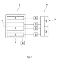
- FIG. 1 shows a schematic representation of a longitudinal section through an embodiment of the device according to the invention when carrying out an embodiment of the method according to the invention.
- FIG. 1 shows a schematic representation of an electric machine 2, which has as components a stator 4 and a rotor 6, both of which are arranged in a housing 8, wherein the stator 4 here at least partially surrounds the rotor 6, possibly completely coaxially.
- a rotation axis 10 is provided for the stator 6, which, for example, extends along a shaft of the electric machine 2, around which the rotor 6 rotates in a motor and / or regenerative operation of the electric machine 2 relative to the stator 4.
- the embodiment of the device 12 comprises as components a control device 14, which in turn comprises a computing unit 16 and a memory unit 18.
- the device 12 comprises at least one measuring device 20 and at least one detection device 22, which are associated with the stator 4 and designed to measure and / or detect at least one operating parameter of the stator 4.
- the device comprises at least one measuring device 24 and at least one detection device 26, which are here assigned to the rotor 6 and designed to measure and / or detect at least one operating parameter of the rotor 6.
- control device 14 and at least one measuring device 20, 24 and / or at least one detection device 22, 26 are or are designed as components or components of the electric machine 2, usually an inverter of the electric machine 2. At least one component is further configured to measure and / or to supply at least one operating parameter of the electric machine 2 during a running operation of the electric machine 2, for example a load operation, and / or in a test stand for the electric machine 2 before the actual operation of the electric machine 2 to capture.
- a voltage applied to the stator 4, a current I S flowing through the stator 4 and a rotational field frequency ⁇ S of the stator 4 are measured by the measuring device 20.
- the rotational field frequency ⁇ S indicates a change in a magnetic field of the stator 4.
- the rotational frequency ⁇ R of the rotor 6 is measured during operation.
- the inductance L S of the stator 4 is detected in the test bed.
- the inductance L R of the rotor 6 is also detected by the detection device 26 in the test stand.
- the inductance or main inductance I H of the entire electric machine 2 is detected in the test bench. Values of the inductances detected in the test stand before the actual operation of the electric machine 2 are stored in the memory unit 18 of the control unit 14.
- the control unit 14 usually the arithmetic unit 16 of the control unit 14, takes into account equations (1) and (2):
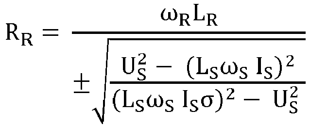
- R R ⁇ R L R ⁇ U S 2 - L S ⁇ S I S 2 L S ⁇ S I S ⁇ 2 - U S 2
- T R R R - R R . Ref ⁇ R R . Ref + T R . Ref determined.
- ⁇ is a coefficient dependent on the material of the rotor 6, the value of which is stored in the memory unit 18.
- a reference value R R , Ref the temperature of the rotor and a reference value T R , Ref the temperature of the rotor 4 to be considered.
- at least one value pair of said reference values R R , Ref , T R, Ref is also stored in the memory unit 18. If a plurality of such value pairs are stored in the memory unit 18, these form, for example, a characteristic curve or a table for a relationship between the temperature and the resistance of the rotor 6.
Abstract
Die Erfindung betrifft ein Verfahren zum Bestimmen einer Temperatur T R eines Rotors (6) einer Elektromaschine (2), der relativ zu einem Stator (4) der Elektromaschine (2) drehbar ist, wobei als Betriebsparameter der Elektromaschine (2) eine am Stator (4) anliegende Spannung U S , ein durch den Stator (4) fließender Strom I S , eine Drehfrequenz É R des Rotors (6), eine Drehfeldfrequenz É S des Stators (4), eine Induktivität L R des Rotors (6), eine Induktivität L S des Stators (4) und eine Hauptinduktivität L H der Elektromaschine (2) ermittelt werden, wobei aus Werten dieser Betriebsparameter ein Wert eines elektrischen Widerstands R R des Rotors (6) nach: R R = É R L R ± U S 2 L S É S I S 2 L S É S I S à 2 U S 2 mit à = 1 L H 2 L S L R berechnet wird, wobei ein Wert der Temperatur T R des Rotors (6) in Abhängigkeit des elektrischen Widerstands R R des Rotors (6) ermittelt wird.The invention relates to a method for determining a temperature TR of a rotor (6) of an electric machine (2), which is rotatable relative to a stator (4) of the electric machine (2) ) applied voltage US, a current IS flowing through the stator (4), a rotational frequency É R of the rotor (6), a rotating field frequency É S of the stator (4), an inductance LR of the rotor (6), an inductance LS of the stator (4) and a main inductance LH of the electric machine (2) are determined, with values of these operating parameters being used to determine a value of an electrical resistance RR of the rotor (6) according to: RR = É RLR ± US 2 ˆ ’LS SIS 2 LS SIS à 2 ˆ ’US 2 with à = 1 ˆ’ LH 2 LSLR is calculated, with a value of the temperature TR of the rotor (6) depending on the electrical resistance RR of the Rotor (6) is determined.
Description
Die Erfindung betrifft ein Verfahren und eine Vorrichtung zum Bestimmen einer Temperatur eines Rotors einer Elektromaschine.The invention relates to a method and a device for determining a temperature of a rotor of an electric machine.
Eine Elektromaschine, die als Generator und/oder als Motor eingesetzt werden kann, umfasst als Komponenten einen feststehenden Stator sowie einen sich relativ zu dem Stator drehenden Rotor. Zum Betreiben der Elektromaschine ist es unter anderem erforderlich, deren Betriebsparameter aktuell zu erfassen. Da sich jedoch der Rotor bei einem Betrieb der Elektromaschine relativ schnell drehen kann, ist es in der Regel nicht möglich, einige Betriebsparameter des Rotors bspw. durch Messung direkt zu erfassen.An electric machine, which can be used as a generator and / or as a motor, comprises as components a fixed stator and a rotor rotating relative to the stator. To operate the electric machine, among other things, it is necessary to currently record their operating parameters. However, since the rotor can rotate relatively quickly during operation of the electric machine, it is usually not possible to directly detect some operating parameters of the rotor, for example by measurement.
Ein Verfahren zum Betreiben einer fremderregten Synchronmaschine ist aus der Druckschrift
Ein elektronisch kommutierter Asynchronmotor, der in der Druckschrift
Bei einem Verfahren zur Drehmomentregelung für einen Induktionsmotor, das aus der Druckschrift
In der Druckschrift
In der Druckschrift
Vor diesem Hintergrund werden ein Verfahren und eine Vorrichtung mit den Merkmalen der unabhängigen Patentansprüche vorgestellt. Ausgestaltungen des Verfahrens und der Vorrichtung gehen aus den abhängigen Patentansprüchen und der Beschreibung hervor.Against this background, a method and a device with the features of the independent claims are presented. Embodiments of the method and the device are evident from the dependent claims and the description.
Das erfindungsgemäße Verfahren ist zum Bestimmen einer Temperatur TR eines Rotors einer Elektromaschine, der relativ zu einem Stator der Elektromaschine drehbar ist, ausgebildet. Dabei werden als Betriebsparameter der Elektromaschine eine am Stator anliegende Spannung US, ein durch den Stator fließender Strom IS, eine Drehfrequenz ωR des Rotors, eine Drehfeldfrequenz ωS des Stators, eine Induktivität LR des Rotors, eine Induktivität LS des Stators und eine Hauptinduktivität LH der Elektromaschine ermittelt. Aus Werten dieser Betriebsparameter wird ein Wert eines elektrischen Widerstands RR des Rotors nach Gleichung (1): 
![]()
![]()
berechnet. Ein aktueller Wert der Temperatur TR des Rotors wird in Abhängigkeit des elektrischen Widerstands RR als Betriebsparameter des Rotors ermittelt.calculated. A current value of the temperature T R of the rotor is determined as a function of the electrical resistance R R as the operating parameter of the rotor.
Aktuelle Werte der am Stator anliegenden Spannung US, des durch den Stator fließenden Stroms IS, der Drehfrequenz ωR des Rotors und der Drehfeldfrequenz ωS des Stators werden üblicherweise von mindestens einem Messgerät betriebsbegleitend, bspw. in einem Lastbetrieb, gemessen und somit erfasst und/oder ermittelt.Actual values of the voltage U S applied to the stator, of the current I S flowing through the stator, of the rotational frequency ω R of the rotor and the rotational field frequency ω S of the stator are usually measured by at least one measuring device during operation, for example in a load operation, and thus detected and / or determined.
Werte der Induktivität LR des Rotors, der Induktivität LS des Stators und der Hauptinduktivität LH der Elektromaschine werden laut einer Vorgabe, bspw. einer Tabelle oder einer Kennlinie, vorgegeben und erfasst.Values of inductance L of the rotor R, the inductance L S of the stator and the main inductance L H of the electric machine according to specifications, for example. A table or a characteristic curve, specified and recorded.
Alternativ oder ergänzend werden Werte der Induktivität LR des Rotors, der Induktivität LS des Stators und der Hauptinduktivität LH der Elektromaschine mit mindestens einem Erfassungsgerät in einem Prüfstand, üblicherweise vor einem Betrieb der Elektromaschine, während dem die anderen Betriebsparameter betriebsbegleitend gemessen werden und die aktuelle Temperatur des Rotors zu ermitteln ist, ermittelt. Dabei wird die Vorgabe in Ausgestaltung auf Grundlage der im Prüfstand ermittelten Werte bereitgestellt.Alternatively or additionally, values of the inductance L R of the rotor, the inductance L S of the stator and the main inductance L H of the electric machine with at least one detection device in a test stand, usually before operation of the electric machine, during which the other operating parameters are measured during operation and the current temperature of the rotor is determined. The specification is provided in an embodiment based on the values determined in the test bench.
In Ausgestaltung wird zum Bestimmen der Temperatur TR des Rotors der in Gleichung (3) dargestellte Zusammenhang zwischen der Temperatur TR und dem Widerstand RR des Rotors verwendet: ![]()
![]()
![]()
![]()
![]()
![]()
Dabei ist RR,Ref ein Referenzwert für den Widerstand RR und TR,Ref ein Referenzwert für die Temperatur TR des Rotors, wobei diese Referenzwerte zueinander korreliert sind und bspw. ebenfalls in dem Prüfstand ermittelt werden. Dabei ist bspw. TR,Ref = 20°C jener Referenzwert der Temperatur TR, bei dem sich aufgrund von Materialeigenschaften des Rotors der Referenzwert RR,Ref des Widerstands ergibt. In Ausgestaltung ist möglich, mehrere Wertepaare von Referenzwerten TR,Ref und RR,Ref zu ermitteln und als Vorgabe zu speichern. Der aktuelle Wert der Temperatur TR wird durch den aktuellen Wert des Widerstands RR in Relation zu TR,Ref und RR,Ref ermittelt. Die einander zugeordneten Referenzwerte TR,Ref und RR,Ref für Temperatur und Widerstand werden in Ausgestaltung ebenfalls im Prüfstand ermittelt.In this case, R R , Ref is a reference value for the resistor R R and T R, Ref is a reference value for the temperature T R of the rotor, these reference values being correlated with one another and, for example, also being determined in the test bench. In this case, for example, T R , Ref = 20 ° C. is the reference value of the temperature T R at which the reference value R R , Ref of the resistance results due to material properties of the rotor. In an embodiment, it is possible to determine a plurality of value pairs of reference values T R , Ref and R R , Ref and to store them as a default. The current value of the temperature T R is determined by the current value of the resistor R R in relation to T R , Ref and R R, Ref . The mutually associated reference values T R , Ref and R R , Ref for temperature and resistance are also determined in the test rig in an embodiment.
Daraus ergibt sich Gleichung (6): ![]()
![]()
Üblicherweise wird der aktuelle Wert der Temperatur TR des Rotors nach Gleichung (7): ![]()
![]()
Die erfindungsgemäße Vorrichtung ist zum Bestimmen einer Temperatur TR eines Rotors einer Elektromaschine, der relativ zu einem Stator der Elektromaschine drehbar ist, ausgebildet und umfasst mindestens ein Messgerät, mindestens ein Erfassungsgerät und ein Steuergerät. Das mindestens eine Messgerät ist dazu ausgebildet, als Betriebsparameter der Elektromaschine eine am Stator anliegende Spannung US, einen durch den Stator fließenden Strom IS, eine Drehfrequenz ωR des Rotors und eine Drehfeldfrequenz ωS des Stators zu messen und somit zu ermitteln. Das mindestens eine Erfassungsgerät ist dazu ausgebildet, eine Induktivität LS des Stators, eine Induktivität LR des Rotors und eine Hauptinduktivität LH der Elektromaschine zu ermitteln. Das Steuergerät ist dazu ausgebildet, aus Werten dieser Betriebsparameter einen Wert eines elektrischen Widerstands RR des Rotors nach: 
![]()
![]()
Hierbei ist ein erstes Messgerät als ein dem Stator zugeordnetes und/oder zuzuordnendes Spannungsmessgerät ausgebildet, das dazu ausgebildet ist, mindestens einen Wert der am Stator anliegenden Spannung US zu messen. Ein zweites Messgerät ist als ein dem Stator zugeordnetes und/oder zuzuordnendes Messgerät ausgebildet, das dazu ausgebildet ist, mindestens einen Wert des durch den Stator fließenden Stroms IS zu erfassen. Ein drittes Messgerät ist als ein dem Rotor zugeordnetes und/oder zuzuordnendes Drehfrequenzmessgerät bzw. Drehzahlmessgerät ausgebildet, das dazu ausgebildet ist, mindestens einen Wert der Drehfrequenz ωR des Rotors zu ermitteln. Ein viertes Messgerät ist als ein dem Stator zugeordnetes und/oder zuzuordnendes Drehfeldfrequenzmessgerät ausgebildet, das dazu ausgebildet ist, mindestens einen Wert der Drehfeldfrequenz ωS des Stators zu messen.In this case, a first measuring device is embodied as a voltage measuring device assigned to the stator and / or to be assigned, which is designed to measure at least one value of the voltage U S applied to the stator. A second measuring device is embodied as a measuring device assigned to and / or associated with the stator and designed to detect at least one value of the current I S flowing through the stator. A third measuring device is embodied as a rotational frequency measuring device or rotational speed measuring device assigned to and / or associated with the rotor, which is designed to determine at least one value of the rotational frequency ω R of the rotor. A fourth measuring device is embodied as a rotating field frequency measuring device assigned to the stator and / or to be assigned, which is designed to measure at least one value of the rotating field frequency ω S of the stator.
Somit werden mit dem mindestens einen Messgerät und/oder Erfassungsgerät Werte von elektrischen sowie mechanischen Betriebsparametern mindestens einer Komponente, d. h. dem Stator und/oder dem Rotor der Elektromaschine gemessen und/oder erfasst.Thus, with the at least one measuring device and / or detection device, values of electrical and mechanical operating parameters of at least one component, i. H. measured and / or detected the stator and / or the rotor of the electric machine.
Das Steuergerät umfasst in der Regel eine Recheneinheit und eine Speichereinheit. Werte der Induktivität LR des Rotors, der Induktivität LS des Stators und der Hauptinduktivität IH der Elektromaschine sind laut einer Vorgabe, bspw. aus einer Tabelle oder Kennlinie, zu erfassen, wobei diese Vorgabe, die als Tabelle oder Kennlinie bereitstellbar ist, in der Speichereinheit gespeichert ist.The control unit usually comprises a computing unit and a memory unit. Values of inductance L R of the rotor, the inductance L S of the stator and the main inductance I H of the electric machine, according to a default, for example. From a table or curve to detect, with this requirement, which can be provided as a table or characteristic in the storage unit is stored.
Die Vorrichtung umfasst außerdem einen Prüfstand, der mehrere Erfassungsgeräte aufweist, wobei ein erstes Erfassungsgerät dem Rotor zugeordnet und/oder zuzuordnen sowie dazu ausgebildet ist, mindestens einen Wert der Induktivität LR des Rotors zu erfassen, wobei ein zweites Erfassungsgerät dem Stator zugeordnet und/oder zuzuordnen sowie dazu ausgebildet ist, mindestens einen Wert der Induktivität LS des Stators zu ermitteln, wobei ein drittes Erfassungsgerät der Elektromaschine zugeordnet und/oder zuzuordnen sowie dazu ausgebildet ist, mindestens einen Wert der Hauptinduktivität LH der Elektromaschine zu ermitteln.The device also comprises a test stand having a plurality of detection devices, wherein a first detection device associated with the rotor and / or assigned and adapted to detect at least one value of the inductance L R of the rotor, wherein a second detection device associated with the stator and / or is assigned and designed to determine at least one value of the inductance L S of the stator, wherein a third detection device associated with the electric machine and / or assigned and is designed to determine at least one value of the main inductance L H of the electric machine.
Üblicherweise dreht sich der Rotor als erste Komponente der Elektromaschine bei einem Betrieb der Elektromaschine relativ zu dem Stator als der zweiten Komponente der Elektromaschine. Dabei weist eine der beiden Komponenten, üblicherweise der Rotor, Permanentmagnete auf, die ein permanentes Magnetfeld erzeugen. Die andere der beiden Komponenten, üblicherweise der Stator, weist dagegen mehrere Spulen auf. Die Elektromaschine ist als Motor und/oder als Generator zu betreiben. Bei einem Betrieb als Motor wird durch die Spulen elektrischer Strom geleitet und somit ein Magnetfeld induziert, das mit dem permanenten Magnetfeld interagiert. Auf diese Weise ist es möglich, mit der Elektromaschine elektrische Energie in mechanische Energie, üblicherweise Rotationsenergie, umzuwandeln. Falls die Elektromaschine alternativ oder ergänzend als Generator betrieben wird, wird der Rotor mechanisch in Rotation versetzt, wobei in den Spulen ein Strom induziert und somit mechanische Energie in elektrische Energie umgewandelt wird.Usually, the rotor rotates as the first component of the electric machine during operation of the electric machine relative to the stator as the second component of the electric machine. In this case, one of the two components, usually the rotor, on permanent magnets, which generate a permanent magnetic field. The other of the two components, usually the stator, in contrast, has several coils. The electric machine is to operate as a motor and / or as a generator. When operated as a motor, electrical current is passed through the coils, thus inducing a magnetic field that interacts with the permanent magnetic field. In this way it is possible to convert electrical energy into mechanical energy, usually rotational energy, with the electric machine. If the electric machine is alternatively or additionally operated as a generator, the rotor is mechanically rotated, wherein a current is induced in the coils and thus mechanical energy is converted into electrical energy.
Bei Durchführung des Verfahrens wird die Temperatur der bspw. als Asynchronmaschine ausgebildeten Elektromaschine über den zu ermittelnden elektrischen Widerstand des Rotors indirekt ermittelt. Somit ist es nicht erforderlich, an dem Rotor einen Temperatursensor bzw. ein Thermometer anzuordnen. Weiterhin ist möglich, mittels eines Temperaturmodells, das als Vorgabe in dem Steuergerät oder einem Umrichter der Elektromaschine gespeichert ist, aus dem erfassten aktuellen Wert des Widerstands des Rotors unter Berücksichtigung einer Abhängigkeit der Temperatur von dem Widerstand den Wert der Temperatur zu ermitteln. In weiterer möglicher Ausgestaltung ist zum Bestimmen der Temperatur des Rotors vorgesehen, auch Werte eines Lastverlaufs der Elektromaschine und/oder einer Temperatur des Stators zu berücksichtigen.When carrying out the method, the temperature of the electric machine designed, for example, as an asynchronous machine is indirectly determined via the electrical resistance of the rotor to be determined. Thus, it is not necessary on the rotor, a temperature sensor or a To arrange thermometer. Furthermore, it is possible, by means of a temperature model, which is stored as a default in the control unit or a converter of the electric machine to determine the value of the temperature from the detected current value of the resistance of the rotor, taking into account a dependence of the temperature of the resistor. In a further possible embodiment, it is provided for determining the temperature of the rotor to also take into account values of a load profile of the electric machine and / or a temperature of the stator.
Im Rahmen des Verfahrens ist es somit nicht mehr erforderlich, die Temperatur des Rotors bei einem Start der Elektromaschine zu kennen. Weiterhin wird die Temperatur berechnet anstatt lediglich abgeschätzt. Das Verfahren ist auch dann durchführbar, falls die Temperatur des Rotors nach einem Wiederstart der Elektromaschine unbekannt sein sollte. Somit ist auch nicht erforderlich, zu wissen, welche Temperatur der Rotor bspw. bei einem Abschalten der Elektromaschine aufgewiesen hat und wieviel Zeit nach Abschalten der Elektromaschine bis zum Wiederstart verstrichen ist.In the context of the method, it is thus no longer necessary to know the temperature of the rotor at a start of the electric machine. Furthermore, the temperature is calculated rather than merely estimated. The method is also feasible if the temperature of the rotor after a restart of the electric machine should be unknown. Thus, it is not necessary to know which temperature the rotor has exhibited, for example, when switching off the electric machine and how much time has elapsed after switching off the electric machine to restart.
Bei Umsetzung des Verfahrens wird für die bspw. als Asynchronmaschine ausgebildete Elektromaschine ein direkter Zusammenhang zwischen dem Widerstand und der Temperatur des Rotors berücksichtigt. Im Betrieb, bspw. Lastbetrieb, der Elektromaschine werden mit dem mindestens einen Messgerät, das bspw. in einem Umrichter der Elektromaschine angeordnet ist, die aktuellen Werte des Stroms und der Spannung des Stators gemessen. Die Drehzahl des Rotors wird bspw. mit einem als Drehzahlgeber ausgebildeten Messgerät gemessen. Aus der gemessenen Drehzahl des Rotors wird weiterhin dessen Drehfrequenz abgeleitet.When implementing the method, a direct relationship between the resistance and the temperature of the rotor is taken into account for the electric machine designed as an asynchronous machine, for example. During operation, for example load operation, of the electric machine, the current values of the current and the voltage of the stator are measured with the at least one measuring device, which is arranged, for example, in a converter of the electric machine. The speed of the rotor is measured, for example, with a designed as a speed sensor measuring device. From the measured speed of the rotor whose rotational frequency is further derived.
Die zu berücksichtigenden Induktivitäten des Rotors, des Stators sowie der gesamten Elektromaschine werden vor dem eigentlichen Betrieb bzw. Lastbetrieb der Elektromaschine als Kenngrößen der Elektromaschine ermittelt. Hierbei ist möglich, im Prüfstand eine jeweilige Spannung, die an dem Stator, dem Rotor und/oder der Elektromaschine anliegt sowie einen Strom, der durch den Stator, den Rotor und/oder die Elektromaschine fließt, zu messen und daraus wiederum die genannten Induktivitäten zu bestimmen. Die in dem Prüfstand ermittelten Werte für die Induktivitäten werden in der Speichereinheit des Steuergeräts hinterlegt. Die aktuelle Drehfeldfrequenz, üblicherweise eine Drehfeldfrequenz des Magnetfelds des Stators, wird von dem Umrichter als das mindestens eine Erfassungsgerät erfasst und/oder ermittelt. Dabei wird dieses Magnetfeld bspw. durch den Strom, der durch die Spulen, üblicherweise Spulen des Stators fließt, induziert.The inductances of the rotor, of the stator and of the entire electric machine to be taken into account before the actual operation or Load operation of the electric machine determined as characteristics of the electric machine. In this case, it is possible to measure in the test bench a respective voltage which is applied to the stator, the rotor and / or the electric machine and to measure a current flowing through the stator, the rotor and / or the electric machine and, in turn, the said inductances determine. The values for the inductances determined in the test bench are stored in the memory unit of the control unit. The current rotating field frequency, usually a rotating field frequency of the magnetic field of the stator, is detected and / or determined by the converter as the at least one detection device. In this case, this magnetic field is, for example, by the current flowing through the coils, usually coils of the stator, induced.
Weitere Vorteile und Ausgestaltungen der Erfindung ergeben sich aus der Beschreibung und der beiliegenden Zeichnung.Further advantages and embodiments of the invention will become apparent from the description and the accompanying drawings.
Es versteht sich, dass die voranstehend genannten und die nachstehend noch zu erläuternden Merkmale nicht nur in der jeweils angegebenen Kombination, sondern auch in anderen Kombinationen oder in Alleinstellung verwendbar sind, ohne den Rahmen der vorliegenden Erfindung zu verlassen.It is understood that the features mentioned above and those yet to be explained below can be used not only in the particular combination indicated, but also in other combinations or in isolation, without departing from the scope of the present invention.
Die Erfindung ist anhand einer Ausführungsform in der Zeichnung schematisch dargestellt und wird unter Bezugnahme auf die Zeichnung schematisch und ausführlich beschrieben.The invention is illustrated schematically with reference to an embodiment in the drawing and will be described schematically and in detail with reference to the drawing.
Die erfindungsgemäße Ausführungsform der Vorrichtung 12 umfasst als Komponenten ein Steuergerät 14, das wiederum eine Recheneinheit 16 und eine Speichereinheit 18 umfasst. Außerdem umfasst die Vorrichtung 12 mindestens ein Messgerät 20 sowie mindestens ein Erfassungsgerät 22, die dem Stator 4 zugeordnet und zum Messen und/oder Erfassen mindestens eines Betriebsparameters des Stators 4 ausgebildet sind. Außerdem umfasst die Vorrichtung mindestens ein Messgerät 24 sowie mindestens ein Erfassungsgerät 26, die hier dem Rotor 6 zugeordnet und zum Messen und/oder Erfassen mindestens eines Betriebsparameters des Rotors 6 ausgebildet sind.The embodiment of the
In Ausgestaltung ist bzw. sind das Steuergerät 14 sowie mindestens ein Messgerät 20, 24 und/oder mindestens ein Erfassungsgerät 22, 26 als Komponente bzw. Komponenten der Elektromaschine 2, üblicherweise eines Umrichters der Elektromaschine 2 ausgebildet. Mindestens eine Komponente ist weiterhin dazu ausgebildet, mindestens einen Betriebsparameter der Elektromaschine 2 bei einem laufenden Betrieb der Elektromaschine 2, bspw. einem Lastbetrieb, und/oder in einem Prüfstand für die Elektromaschine 2 vor dem eigentlichen Betrieb der Elektromaschine 2 zu messen und/oder zu erfassen.In an embodiment, the
Dabei wird von dem Messgerät 20 eine an dem Stator 4 anliegende Spannung, ein durch den Stator 4 fließender Strom IS sowie eine Drehfeldfrequenz ωS des Stators 4 gemessen. Dabei gibt die Drehfeldfrequenz ωS eine Änderung eines Magnetfelds des Stators 4 an. Von dem Messgerät 24 wird die Drehfrequenz ωR des Rotors 6 betriebsbegleitend gemessen. Von dem Erfassungsgerät 22 wird im Prüfstand die Induktivität LS des Stators 4 erfasst. Außerdem wird von dem Erfassungsgerät 26 ebenfalls im Prüfstand die Induktivität LR des Rotors 6 erfasst. Mit einem weiteren Erfassungsgerät 28, das der Elektromaschine 2 und somit dem Rotor 4 und dem Stator 6 zugeordnet ist, wird in dem Prüfstand die Induktivität bzw. Hauptinduktivität IH der gesamten Elektromaschine 2 erfasst. Werte der Induktivitäten, die im Prüfstand vordem eigentlichen Betrieb der Elektromaschine 2 erfasst werden, werden in der Speichereinheit 18 des Steuergeräts 14 gespeichert.In this case, a voltage applied to the
Unter Berücksichtigung der Werte der als Induktivitäten ausgebildeten Betriebsparameter sowie der betriebsbegleitend zu messenden Drehfrequenz, Drehfeldfrequenz und Ströme wird von dem Steuergerät 14, üblicherweise der Recheneinheit 16 des Steuergeräts 14, unter Berücksichtigung der Gleichungen (1) und (2): 
![]()
![]()
![]()
![]()
Claims (8)


Applications Claiming Priority (1)
| Application Number | Priority Date | Filing Date | Title |
|---|---|---|---|
| DE102015012902.3A DE102015012902A1 (en) | 2015-10-06 | 2015-10-06 | Method for determining a temperature of a rotor |
Publications (1)
| Publication Number | Publication Date |
|---|---|
| EP3157165A1 true EP3157165A1 (en) | 2017-04-19 |
Family
ID=57042733
Family Applications (1)
| Application Number | Title | Priority Date | Filing Date |
|---|---|---|---|
| EP16191366.0A Ceased EP3157165A1 (en) | 2015-10-06 | 2016-09-29 | Method for determining a temperature of a rotor |
Country Status (2)
| Country | Link |
|---|---|
| EP (1) | EP3157165A1 (en) |
| DE (1) | DE102015012902A1 (en) |
Cited By (2)
| Publication number | Priority date | Publication date | Assignee | Title |
|---|---|---|---|---|
| CN110611473A (en) * | 2018-06-05 | 2019-12-24 | 庞巴迪运输有限公司 | Method and device for determining the temperature of a rotor |
| DE102021212801A1 (en) | 2021-11-15 | 2023-05-17 | Mahle International Gmbh | Method of determining a temperature in a rotor excitation circuit |
Citations (7)
| Publication number | Priority date | Publication date | Assignee | Title |
|---|---|---|---|---|
| DE1003301B (en) | 1955-05-16 | 1957-02-28 | Bbc Brown Boveri & Cie | Process for the production of high voltage insulation, especially for the winding of electrical machines |
| DE3707614A1 (en) * | 1987-03-10 | 1988-09-22 | Klein Schanzlin & Becker Ag | Method for determining the rotor resistance of an asynchronous machine |
| AT397322B (en) | 1991-02-20 | 1994-03-25 | Elin Energieanwendung | Control system for an intermediate-circuit voltage converter |
| DE102008018843A1 (en) | 2007-05-14 | 2008-11-20 | Ebm-Papst St. Georgen Gmbh & Co. Kg | Electronically commutated asynchronous motor |
| EP2120329A2 (en) | 2008-05-16 | 2009-11-18 | Square D Company | Method and apparatus for estimating the rotor temperature of an induction motor |
| CN102072779A (en) * | 2010-11-17 | 2011-05-25 | 哈尔滨工业大学 | Rotor-groove harmonic analysis based method for identifying temperature of sensorless rotor for submersible motor |
| DE102010014173A1 (en) | 2009-04-29 | 2011-06-16 | Sew-Eurodrive Gmbh & Co. Kg | Method for operating separately-excited synchronous machine i.e. three-phase machine, involves determining rotor flux by machine model based on magnetization characteristics of exciting current supplied to excitation winding of rotor |
-
2015
- 2015-10-06 DE DE102015012902.3A patent/DE102015012902A1/en not_active Ceased
-
2016
- 2016-09-29 EP EP16191366.0A patent/EP3157165A1/en not_active Ceased
Patent Citations (7)
| Publication number | Priority date | Publication date | Assignee | Title |
|---|---|---|---|---|
| DE1003301B (en) | 1955-05-16 | 1957-02-28 | Bbc Brown Boveri & Cie | Process for the production of high voltage insulation, especially for the winding of electrical machines |
| DE3707614A1 (en) * | 1987-03-10 | 1988-09-22 | Klein Schanzlin & Becker Ag | Method for determining the rotor resistance of an asynchronous machine |
| AT397322B (en) | 1991-02-20 | 1994-03-25 | Elin Energieanwendung | Control system for an intermediate-circuit voltage converter |
| DE102008018843A1 (en) | 2007-05-14 | 2008-11-20 | Ebm-Papst St. Georgen Gmbh & Co. Kg | Electronically commutated asynchronous motor |
| EP2120329A2 (en) | 2008-05-16 | 2009-11-18 | Square D Company | Method and apparatus for estimating the rotor temperature of an induction motor |
| DE102010014173A1 (en) | 2009-04-29 | 2011-06-16 | Sew-Eurodrive Gmbh & Co. Kg | Method for operating separately-excited synchronous machine i.e. three-phase machine, involves determining rotor flux by machine model based on magnetization characteristics of exciting current supplied to excitation winding of rotor |
| CN102072779A (en) * | 2010-11-17 | 2011-05-25 | 哈尔滨工业大学 | Rotor-groove harmonic analysis based method for identifying temperature of sensorless rotor for submersible motor |
Cited By (2)
| Publication number | Priority date | Publication date | Assignee | Title |
|---|---|---|---|---|
| CN110611473A (en) * | 2018-06-05 | 2019-12-24 | 庞巴迪运输有限公司 | Method and device for determining the temperature of a rotor |
| DE102021212801A1 (en) | 2021-11-15 | 2023-05-17 | Mahle International Gmbh | Method of determining a temperature in a rotor excitation circuit |
Also Published As
| Publication number | Publication date |
|---|---|
| DE102015012902A1 (en) | 2017-04-06 |
Similar Documents
| Publication | Publication Date | Title |
|---|---|---|
| DE112013005190T5 (en) | Improvements in electric power steering systems | |
| DE102013004954B4 (en) | Method for operating a multi-phase electrical machine and corresponding multi-phase electrical machine | |
| DE102015121340B4 (en) | Cogging torque measuring device for a motor | |
| DE102014016452B4 (en) | Method for determining a stator winding temperature of an electrical machine | |
| DE102005062588A1 (en) | Permanently excited synchronous machine`s magnet temperature determining method, involves measuring phase voltage and rotational speed of machine, and determining magnet temperature of machine from measured phase voltage and speed | |
| WO2018082902A1 (en) | Method for determining a rotational angle position of a crankshaft of an internal combustion engine | |
| EP2026461B1 (en) | Method for sensorless control of a three-phase machine | |
| DE102017007422A1 (en) | Method for determining manufacturing tolerances of an electrical machine | |
| DE102009020473B4 (en) | Procedure for error detection when controlling a rotating field motor | |
| EP3157165A1 (en) | Method for determining a temperature of a rotor | |
| EP3838498B1 (en) | Electric tool, measuring device and method for operating an electric tool | |
| EP3422557B1 (en) | Method for detecting load differences | |
| DE102018130495A1 (en) | Procedure for the current condition monitoring of an electric motor | |
| DE102015107501A1 (en) | Determination of motor temperature as demagnetization protection | |
| EP2360830B1 (en) | Method and device for simulating an electromechanical converter | |
| EP3602772B1 (en) | Method of operation for an electric motor, and soft starter | |
| DE102014211881A1 (en) | Method for checking a position of a rotor of an electrical machine | |
| EP1383231B1 (en) | Method for acquiring the magnetic flux, the rotor position and/or the rotation speed | |
| DE102018002188A1 (en) | Method for testing a drive and drive | |
| EP3529890B1 (en) | Control system for a synchronous machine and method for operating a synchronous machine | |
| EP1985006A2 (en) | Method and device for determining the torque of an electric machine | |
| EP1959552B1 (en) | Method and device for operating an electric machine | |
| EP3704790B1 (en) | Method for determining the rotor position of synchronously running electric machines without a mechanical sensor | |
| EP3556011B1 (en) | Method for determining the angular position of the rotor of an inverter-fed synchronous motor, and apparatus for carrying out the method | |
| DE102010000991A1 (en) | Phase cutoff detection method for e.g. permanently excited synchronous machine of drive device, involves examining longitudinal current to find whether actual phase currents correspond to target current according to current level |
Legal Events
| Date | Code | Title | Description |
|---|---|---|---|
| PUAI | Public reference made under article 153(3) epc to a published international application that has entered the european phase |
Free format text: ORIGINAL CODE: 0009012 |
|
| AK | Designated contracting states |
Kind code of ref document: A1 Designated state(s): AL AT BE BG CH CY CZ DE DK EE ES FI FR GB GR HR HU IE IS IT LI LT LU LV MC MK MT NL NO PL PT RO RS SE SI SK SM TR |
|
| AX | Request for extension of the european patent |
Extension state: BA ME |
|
| 17P | Request for examination filed |
Effective date: 20171019 |
|
| RBV | Designated contracting states (corrected) |
Designated state(s): AL AT BE BG CH CY CZ DE DK EE ES FI FR GB GR HR HU IE IS IT LI LT LU LV MC MK MT NL NO PL PT RO RS SE SI SK SM TR |
|
| 17Q | First examination report despatched |
Effective date: 20181029 |
|
| STAA | Information on the status of an ep patent application or granted ep patent |
Free format text: STATUS: THE APPLICATION HAS BEEN REFUSED |
|
| 18R | Application refused |
Effective date: 20191206 |