EP3156618A1 - Engine - Google Patents
Engine Download PDFInfo
- Publication number
- EP3156618A1 EP3156618A1 EP16190756.3A EP16190756A EP3156618A1 EP 3156618 A1 EP3156618 A1 EP 3156618A1 EP 16190756 A EP16190756 A EP 16190756A EP 3156618 A1 EP3156618 A1 EP 3156618A1
- Authority
- EP
- European Patent Office
- Prior art keywords
- rocker
- shaft
- rocker arm
- engine
- arm
- Prior art date
- Legal status (The legal status is an assumption and is not a legal conclusion. Google has not performed a legal analysis and makes no representation as to the accuracy of the status listed.)
- Granted
Links
Images











Classifications
-
- F—MECHANICAL ENGINEERING; LIGHTING; HEATING; WEAPONS; BLASTING
- F01—MACHINES OR ENGINES IN GENERAL; ENGINE PLANTS IN GENERAL; STEAM ENGINES
- F01L—CYCLICALLY OPERATING VALVES FOR MACHINES OR ENGINES
- F01L1/00—Valve-gear or valve arrangements, e.g. lift-valve gear
- F01L1/12—Transmitting gear between valve drive and valve
- F01L1/18—Rocking arms or levers
- F01L1/181—Centre pivot rocking arms
-
- F—MECHANICAL ENGINEERING; LIGHTING; HEATING; WEAPONS; BLASTING
- F01—MACHINES OR ENGINES IN GENERAL; ENGINE PLANTS IN GENERAL; STEAM ENGINES
- F01L—CYCLICALLY OPERATING VALVES FOR MACHINES OR ENGINES
- F01L1/00—Valve-gear or valve arrangements, e.g. lift-valve gear
- F01L1/26—Valve-gear or valve arrangements, e.g. lift-valve gear characterised by the provision of two or more valves operated simultaneously by same transmitting-gear; peculiar to machines or engines with more than two lift-valves per cylinder
- F01L1/267—Valve-gear or valve arrangements, e.g. lift-valve gear characterised by the provision of two or more valves operated simultaneously by same transmitting-gear; peculiar to machines or engines with more than two lift-valves per cylinder with means for varying the timing or the lift of the valves
-
- F—MECHANICAL ENGINEERING; LIGHTING; HEATING; WEAPONS; BLASTING
- F01—MACHINES OR ENGINES IN GENERAL; ENGINE PLANTS IN GENERAL; STEAM ENGINES
- F01L—CYCLICALLY OPERATING VALVES FOR MACHINES OR ENGINES
- F01L13/00—Modifications of valve-gear to facilitate reversing, braking, starting, changing compression ratio, or other specific operations
- F01L13/0015—Modifications of valve-gear to facilitate reversing, braking, starting, changing compression ratio, or other specific operations for optimising engine performances by modifying valve lift according to various working parameters, e.g. rotational speed, load, torque
- F01L13/0036—Modifications of valve-gear to facilitate reversing, braking, starting, changing compression ratio, or other specific operations for optimising engine performances by modifying valve lift according to various working parameters, e.g. rotational speed, load, torque the valves being driven by two or more cams with different shape, size or timing or a single cam profiled in axial and radial direction
Definitions
- the present invention relates to an engine.
- Japan Laid-open Patent Application Publication No. 2015-010552 describes that the low speed rocker arm and the high speed rocker arm are attached to a rocker shaft while being aligned in the axial direction of the rocker shaft.
- the low speed rocker arm is configured to be driven by a low speed cam, and in conjunction with this, valves are configured to be opened and closed.
- the high speed rocker arm and the high speed rocker arm are configured to be coupled.
- a coupling pin inserted into a hole of the low speed rocker arm, is configured to be moved by an actuator and be inserted into a hole of the high speed rocker arm.
- the inventor of the present application conceived of increasing the diameter of a coupling pin as a measure to enhance stiffness of coupling.
- the mass of the coupling pin increases with increase in diameter of the coupling pin.
- each rocker arm is enlarged in a part in which the coupling pin is inserted.
- the mass of each rocker arm also increases.
- the inertia mass of the entire rocker unit increases. This results in a drawback of deteriorating behavior of the rocker arms.
- the drawback of behavior deterioration is remarkable in straddled vehicles, because the high speed range of engine speed is even used in straddled vehicles in comparison with automobiles.
- An engine includes a cylinder head, a valve, a rocker unit, a camshaft and an opening and closing timing changer.
- the valve is attached to the cylinder head.
- the rocker unit is configured to open/close the valve by pressing the valve.
- the camshaft is configured to drive the rocker unit.
- the opening and closing timing changer is configured to change timing of opening and closing the valve.
- the rocker unit includes a rocker shaft, a first rocker arm, a second rocker arm, a pressing member and a coupling pin.
- the rocker shaft is supported by the cylinder head.
- the first rocker arm includes a first attachment portion and a first contact portion.
- the first attachment portion is attached to the rocker shaft.
- the first contact portion is connected to the first attachment portion and is mounted to be contactable with the camshaft.
- the first rocker arm is configured to be rotated about an axis of the rocker shaft when the first contact portion makes contact with the camshaft.
- the second rocker arm includes a second attachment portion and a second contact portion.
- the second attachment portion is attached to the rocker shaft.
- the second contact portion is connected to the second attachment portion and is mounted to be contactable with the camshaft.
- the second rocker arm is disposed in alignment with the first rocker arm in a direction of the axis of the rocker shaft.
- the second rocker arm is configured to be rotated about the axis of the rocker shaft when the second contact portion makes contact with the camshaft.
- the rocker shaft includes a shaft member and a collar member.
- the shaft member includes a first end and a second end.
- the first end is one end of the shaft member in the direction of the axis of the rocker shaft, whereas the second end is the other end of the shaft member in the direction of the axis of the rocker shaft.
- the first end is supported by the first shaft support portion.
- the second end is supported by the second shaft support portion.
- the collar member is provided separately from the shaft member.
- the collar member is disposed between the first end and the second end in the direction of the axis of the rocker shaft
- the first and second rocker arms are attached to the collar member.
- the collar member has an outer diameter larger than each of an outer diameter of the first end and an outer diameter of the second end.
- the shaft member is inserted into a hole provided in the collar member.
- each of the first and second ends has the outer diameter smaller than that of the collar member.
- the collar member may be rotatable relatively to the shaft member. There are chances that each of the first and second rocker arms is pressed to the rocker shaft due to factors such as positional tolerance in attaching each of the first and second rocker arms to the rocker shaft. Even in this case, increase in drive loss of the first rocker arm and that of the second rocker arm can be inhibited by the construction that the collar member is rotated relatively to the shaft member.
- the rocker shaft hole may have an inner diameter smaller than the outer diameter of the collar member. In this case, it is possible to easily and reliably produce the first shaft support portion with a required level of thickness.
- a boundary between the first rocker arm and the second rocker arm may be disposed closer to either the first shaft support portion or the second shaft support portion than a middle position between the first shaft support portion and the second shaft support portion.
- large stress possibly acts on either the first shaft support portion or the second shaft support portion.
- bending deformation of the rocker shaft can be reduced by enhancing stiffness of coupling in the rocker unit.
- the engine may be a single-cylinder engine.
- FIG. 1 is a side view of a straddled vehicle 100.
- the straddled vehicle 100 is a motorcycle of a so-called scooter type.
- the straddled vehicle 100 includes a front wheel 101, a seat 102, a rear wheel 103, a power unit 104, a steering device 105 and a vehicle body cover 106.
- the vehicle body cover 106 includes a rear cover 108, a lower cover 109 and a front cover 110.
- the rear cover 108 is disposed below the seat 102.
- the front cover 110 covers the surroundings of the steering device 105.
- the lower cover 109 is disposed between the front cover 110 and the rear cover 108.
- the lower cover 109 includes a foot rest 111 and a tunnel portion 112 on its top surface.
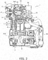
- FIG. 2 is a cross-sectional view of portion of the engine 1 according to the preferred embodiment.
- the engine 1 is a single-cylinder engine of a water cooling type. As shown in FIG. 2 , the engine 1 includes a crankcase 2, a cylinder body 3, a cylinder head 4 and a head cover 5.
- the term "head cover side” is one side of the direction of a cylinder axis Ax1 of the cylinder body 3, and indicates a direction from the cylinder head 4 to the head cover 5.
- the term “cylinder body side” is the other side of the direction of the cylinder axis Ax1, and indicates a direction from the cylinder head 4 to the cylinder body 3.
- crank axis Ax2 As shown in FIG. 2 , the cylinder axis Ax1 is arranged perpendicular to a center axis Ax2 of the crankshaft 6 (hereinafter referred to as "crank axis Ax2").
- the cylinder head 4 includes a combustion chamber 11.
- a spark plug 12 is attached to the cylinder head 4.
- the tip end of the spark plug 12 is disposed to face the combustion chamber 11.
- the base end of the spark plug 12 is disposed outside the engine 1.
- a valve actuating mechanism 13 is accommodated in the cylinder head 4 and the head cover 5.
- the camshaft 14 includes a rod portion 143, a first intake cam portion 144, a second intake cam portion 145 and an exhaust cam 146.
- the rod portion 143 is rotatably supported by first and second shaft support portions 21 and 22 of the cylinder head 4.
- the first intake cam portion 144, the second intake cam portion 145 and the exhaust cam 146 are disposed on the outer periphery of the rod portion 143.
- the first intake cam portion 144, the second intake cam portion 145 and the exhaust cam 146 are disposed in alignment in the direction of the cam axis Ax3.
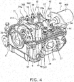
- FIGS. 4 and 5 are perspective views of the interior of the cylinder head 4.
- FIG. 6 is a view of the interior of the cylinder head 4 as seen from the direction of the cylinder axis Ax1.
- the cylinder head 4 includes the first shaft support portion 21 and the second shaft support portion 22.
- the first and second shaft support portions 21 and 22 are integrally provided on the cylinder head 4.
- the first and second shaft support portions 21 and 22 are disposed in alignment in the direction of the cam axis Ax3.
- a head cover side end 21 a of the first shaft support portion 21 is located on the head cover side of the sidewall end 4b of the cylinder head 4. In other words, the first shaft support portion 21 protrudes to the head cover side further than the sidewall end 4b of the cylinder head 4.
- a head cover side end 22a of the second shaft support portion 22 is located on the head cover side of the sidewall end 4b of the cylinder head 4. In other words, the second shaft support portion 22 protrudes to the head cover side further than the sidewall end 4b of the cylinder head 4.
- the intake valves 27 and 28 are configured to open and close the intake port 31. As shown in FIG. 6 , the intake valves 27 and 28 includes a first intake valve 27 and a second intake valve 28. The first and second intake valves 27 and 28 are disposed in alignment in the direction of the cam axis Ax3.
- an intake valve spring 271 is attached to the first intake valve 27.
- the intake valve spring 271 urges the first intake valve 27 in a direction to cause the first intake valve 27 to close the intake port 31.
- an intake valve spring 281 is attached to the second intake valve 28, and urges the second intake valve 28 in a direction to cause the second intake valve 28 to close the intake port 31.
- the exhaust valves 25 and 26 are configured to open and close the exhaust port 32.
- the exhaust valves 25 and 26 includes a first exhaust valve 25 and a second exhaust valve 26.
- the first and second exhaust valves 25 and 26 are disposed in alignment in the direction of the cam axis Ax3.
- an exhaust valve spring 251 is attached to the first exhaust valve 25.
- the exhaust valve spring 251 urges the first exhaust valve 25 in a direction to cause the first exhaust valve 25 to close the exhaust port 32.
- an exhaust valve spring 261 is attached to the second exhaust valve 26, and urges the second exhaust valve 26 in a direction to cause the second exhaust valve 26 to close the exhaust port 32.
- the exhaust rocker arm 36 is supported by the exhaust rocker shaft 35 and is thereby pivotable about the exhaust rocker shaft 35.
- the exhaust rocker arm 36 is disposed to be capable of actuating the exhaust valves 25 and 26.
- the exhaust rocker arm 36 includes a roller 37 and an arm portion 39.
- the pressing member 38 is integrally provided on the arm portion 39. As shown in FIGS. 5 and 6 , the pressing member 38 is provided with first and second adjuster screws 365 and 366 on its tip. The tip of the first adjuster screw 365 faces the stem end of the first exhaust valve 25. As shown in FIG. 7 , the tip of the second adjuster screw 366 faces the stem end of the second exhaust valve 26.
- the exhaust rocker arm 36 pivots. In conjunction with this, the pressing member 38 downwardly presses the first and second exhaust valves 25 and 26. Accordingly, the exhaust port 32 is opened.
- the first and second exhaust valves 25 and 26 are upwardly pressed by the exhaust valve springs 251 and 261. Accordingly, the exhaust port 32 is closed.
- the first rocker arm 42 is provided with a first coupling hole 422.
- the first coupling hole 422 is located on the head cover side of the intake rocker shaft 41.
- the first coupling hole 422 extends in the direction of the cam axis Ax3.
- the coupling pin 45 is inserted into the first coupling hole 422.
- the first rocker arm 42 includes a first arm portion 420 and a first contact portion 423.
- the first contact portion 423 is mounted while being contactable with the first intake cam portion 144.
- the first contact portion 423 is a roller rotatably supported by the first arm portion 420.
- the first contact portion 423 is configured to be rotated by rotation of the first intake cam portion 144.
- the rotational center axis of the first contact portion 423 is arranged in parallel to the cam axis Ax3.
- the second rocker arm 43 is supported while being pivotable about the intake rocker shaft 41.
- the second rocker arm 43 is disposed in alignment with the first rocker arm 42 in the direction of the cam axis Ax3.
- the second rocker arm 43 is disposed on the cam chain chamber 16 side of the first rocker arm 42.
- the second rocker arm 43 includes a second attachment portion 431.
- the second attachment portion 431 is a hole provided in the second rocker arm 43.
- the intake rocker shaft 41 is inserted into the second attachment portion 431.
- the second rocker arm 43 is provided with a second coupling hole 432.
- the second coupling hole 432 is located on the head cover side of the intake rocker shaft 41.
- the second coupling hole 432 extends in the direction of the cam axis Ax3.
- the second coupling hole 432 is disposed while overlapping with the first coupling hole 422 in the direction of the cam axis Ax3. Therefore, the coupling pin 45 is insertable into the second coupling hole 432 of the second rocker arm 43.
- the hardened layer is, for instance, DLC (diamond-like carbon).
- the intake rocker unit 34 includes an arm urging member 46, a first support member 47 and a second support member 48.
- the arm urging member 46 urges the second rocker arm 43 in a direction that the second contact portion 433 is pressed onto the camshaft 14.
- the arm urging member 46 is a coil spring through which the intake rocker shaft 41 is inserted.
- the first support member 47 supports an end of the arm urging member 46.
- the first support member 47 has a shape of a pin and protrudes from the second rocker arm 43 in the direction of the cam axis Ax3.
- the intake rocker unit 34 includes the pin urging member 59.
- the pin urging member 59 is disposed inside the first coupling hole 422.
- the pin urging member 59 urges the coupling pin 45 in a direction from the coupled position to the decoupled position. Therefore, when the coupling pin 45 is not being pressed by the opening and closing timing changer 49, the coupling pin 45 is kept in the decoupled position by the pin urging member 59.
- the coupling pin 45 is pressed by the opening and closing timing changer 49, the coupling pin 45 is moved from the decoupled position to the coupled position against the urging force of the pin urging member 59.
- FIG. 11 shows a condition that when the coupling pin 45 is located in the coupled position, the second contact portion 433 is pressed and lifted up by the second intake cam portion 145.
- the first rocker arm 42 is coupled to the second rocker arm 43 and unitarily pivot therewith.
- the second rocker arm 43 pivots about the intake rocker shaft 41.
- the first rocker arm 42 also pivots in a direction that the pressing member 44 tilts down.
- the first rocker arm 42 pivots independently from the second rocker arm 43.
- the first rocker arm 42 is pivots about the intake rocker shaft 41 in a direction that the pressing member 44 tilts down.
- the first and second intake valves 27 and 28 perform opening and closing motions in accordance with rotation of the second intake cam portion 145.
- rotation of the second intake cam portion 145 is not transmitted to the first rocker arm 42. Therefore, when the coupling pin 45 is located in the decoupled position, the first and second intake valves 27 and 28 perform opening and closing motions in accordance with rotation of the first intake cam portion 144.
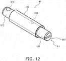
- FIG. 12 is a perspective view of the intake rocker shaft 41.
- the intake rocker shaft 41 includes a shaft member 51 and a collar member 52.
- the shaft member 51 and the collar member 52 are provided as separate members.
- the collar member 52 has a shape of a tube.
- the shaft member 51 is inserted into a hole 521 of the collar member 52.
- the shaft member 51 is not fixed to the collar member 52. Therefore, the collar member 52 is rotatable relatively to the shaft member 51.
- the shaft member 51 includes a first end 511 and a second end 512.
- the first end 511 is one end of the shaft member 51 in the axial direction of the intake rocker shaft 41.
- the second end 512 is the other end of the shaft member 51 in the axial direction of the intake rocker shaft 41.
- the first end 511 protrudes from the collar member 52 to one side in the axial direction of the intake rocker shaft 41.
- the second end 512 protrudes from the collar member 52 to the other side in the axial direction of the intake rocker shaft 41.
- the first end 511 is supported by the first shaft support portion 21.
- the first shaft support portion 21 is provided with a first rocker shaft hole 212.
- the first rocker shaft hole 212 is disposed adjacently to the first camshaft hole 211.
- the first rocker shaft hole 212 penetrates the first shaft support portion 21 in the direction of the cam axis Ax3.
- the first end 511 is inserted into the first rocker shaft hole 212.
- the end surface of the first end 511 is disposed to face the cam chain chamber 16.
- the second end 512 is supported by the second shaft support portion 22.
- the second shaft support portion 22 is provided with a second rocker shaft hole 223.
- the second rocker shaft hole 223 is disposed adjacently to the second camshaft hole 221.
- the second rocker shaft hole 223 does not penetrate the second shaft support portion 22. It should be noted that the second rocker shaft hole 223 may penetrate the second shaft support portion 22.
- the second end 512 is inserted into the second rocker shaft hole 223.
- a boundary B between the first coupling hole 422 of the first rocker arm 42 and the second coupling hole 432 of the second rocker arm 43 is located closer to the second end 512 than a middle position M located in the middle of an interval L between the first end 511 and the second end 512.
- a distance L2 from the boundary B to the second end 512 is shorter than a distance L1 from the boundary B to the first end 511 (L2 ⁇ L1).
- the first end 511 is provided with a lock groove 513 on its end surface.
- the shaft member 51 is attachable to or detachable from the first rocker shaft hole 212 by operating the tool.
- the collar member 52 is provided separately from the shaft member 51.
- the collar member 52 is disposed between the first end 511 and the second end 512 in the axial direction of the intake rocker shaft 41.
- the collar member 52 is disposed between the first shaft support portion 21 and the second shaft support portion 22.
- the first and second rocker arms 42 and 43 are attached to the collar member 52.
- the collar member 52 is inserted into the first attachment portion 421 of the first rocker arm 42 and the second attachment portion 431 of the second rocker arm 43.
- the arm urging member 46 and the second support member 48 are also attached to the collar member 52.
- the outer diameter of the collar member 52 to which the first and second rocker arms 42 and 43 are attached is larger than that of the first end 511 of the shaft member 51 and is also larger than that of the second end 512 of the shaft member 51.
- the outer diameter of the first end 511 is smaller than that of the collar member 52.
- the first rocker shaft hole 212 is disposed adjacently to the first camshaft hole 211. Therefore, when the first rocker shaft hole 212 is constructed to have a large outer diameter, it is concerned that the thickness of a portion between the first rocker shaft hole 212 and the first camshaft hole 211 becomes thin and this results in crack formation in the first shaft support portion 21. To cope with this concern, it can be assumed that the portion between the first rocker shaft hole 212 and the first camshaft hole 211 is constructed to have a large thickness while the first rocker shaft hole 212 is constructed to have a large outer diameter. In this case, however, it is inevitable that the first shaft support portion 21 is entirely enlarged. It is thus concerned that the cylinder head 4 is increased in size.
- enlargement of the first rocker shaft hole 212 can be inhibited by the aforementioned construction of the intake rocker shaft 41. Therefore, crack formation in the first shaft support portion 21 can be inhibited, and simultaneously, increase in size of the cylinder head 4 can be inhibited.
- the first shaft support portion 21 protrudes to the head cover side further than the sidewall end 4b.
- the head cover side end 21 a of the first shaft support portion 21 is not supported by the other portion of the cylinder head 4.
- the head cover side end 21 a is a free end.
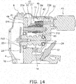
- FIGS. 13 and 14 show the cylinder head 4 according to a first modification.
- the sidewall end 4b is located on the further head cover side than that of the aforementioned preferred embodiment such that the end 21a of the first shaft support portion 21 and the sidewall end 4b are located in the same position in the cylinder axial direction.
- the end 21 a of the first shaft support portion 21 can be connected to and supported by the sidewall 4a of the cylinder head 4. Therefore, the first shaft support portion 21 has high stiffness.
- the protruding portion of the first shaft support portion 21 has low stiffness, and large stress is likely to act on the first shaft support portion 21 in running the engine 1.
- first rocker arm 42 includes the roller as the first contact portion 423
- second rocker arm 43 includes the slipper as the second contact portion 433.
- the roller provided as the first contact portion 423 drive loss with respect to the rocker shaft corresponding to a low speed range can be more reduced than when the first contact portion 423 has a slipper and is processed with surface finishing.
- the second contact portion 433 has the slipper, inertia mass, exerting a great impact in a high speed range, can be more reduced than when a roller is provided as the second contact portion 433, and simultaneously, drive loss can be inhibited equivalently to when the roller is provided as the second contact portion 433.
- the first contact portion 423 may be a slipper which is integrally provided on the first rocker arm 42.
- each of the first and second contact portions 423 and 433 may be a slipper.
- the first contact portion 423 may be a first roller rotatably supported by the first arm portion 420, whereas the second contact portion 433 may be a second roller rotatably supported by the second arm portion 430.
- the mechanism configured to switch the timing of opening and closing valves by the opening and closing timing changer 49 is applied to the intake valves.
- this mechanism may be applied to the exhaust valves.
- the rocker shaft structure including the shaft member 51 and the collar member 52 may be applied to the exhaust rocker shaft.
- the coupling pin 45 may be configured to be driven by a hydraulic pump (opening and closing timing changer).
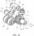
- the first rocker arm 42 is provided with a first oil chamber 42r and an oil channel 42m. Oil in the first oil chamber 42r can be compressed and decompressed through the oil channel 42m.
- the second rocker arm 43 is provided with a second oil chamber 43r and an oil channel 43m. Oil in the second oil chamber 43r can be compressed and decompressed through the oil channel 43m.
- the pressing member 44 is provided with a pin hole 45r.
- the pin hole 45r communicates with the first and second oil chambers 42r and 43r.
- the pin hole 45r accommodates the coupling pin 45. With this construction, in conjunction with displacement of the coupling pin 45 by hydraulic pressure, the pressing member 44 can be selectively coupled to either the first rocker arm 42 or the second rocker arm 43.
- the first and second rocker arms 42 and 43 may be provided with the pressing members 44a and 44b.
- the first rocker arm 42 may be provided with a first pressing member 44a
- the second rocker arm 43 may be provided with a second pressing member 44b.
- the first pressing member 44a when the coupling pin 45 is located in the decoupled position, the first pressing member 44a, provided on the first rocker arm 42, preferably presses the first intake valve 27 in conjunction with rotation of the first rocker arm 42.
- the second pressing member 44b provided on the second rocker arm 43, preferably presses the second intake valve 28 in conjunction with rotation of the second rocker arm 43.
Landscapes
- Engineering & Computer Science (AREA)
- Mechanical Engineering (AREA)
- General Engineering & Computer Science (AREA)
- Valve Device For Special Equipments (AREA)
- Valve-Gear Or Valve Arrangements (AREA)
Abstract
Description
- The present invention relates to an engine.
- There is a type of engine equipped with a variable valve timing actuating mechanism as an engine. The variable valve timing actuating mechanism includes a low speed rocker arm and a high speed rocker arm. The low speed rocker arm is configured to be used in a low speed range of engine speed, whereas the high speed rocker arm is configured to be used in a high speed range of engine speed.
- For example, Japan Laid-open Patent Application Publication No.
2015-010552 - In the aforementioned variable valve timing actuating mechanism, the low speed rocker arm, the high speed rocker arm and the rocker shaft compose a rocker unit. When the rocker unit has low stiffness of coupling, this adversely affects actuation stability of the variable valve timing actuating mechanism. To countermeasure this, enhancement in stiffness of coupling was examined.
- First, the inventor of the present application conceived of increasing the diameter of a coupling pin as a measure to enhance stiffness of coupling. However, the mass of the coupling pin increases with increase in diameter of the coupling pin. Additionally, each rocker arm is enlarged in a part in which the coupling pin is inserted. Hence, the mass of each rocker arm also increases. As a result, the inertia mass of the entire rocker unit increases. This results in a drawback of deteriorating behavior of the rocker arms. Especially, the drawback of behavior deterioration is remarkable in straddled vehicles, because the high speed range of engine speed is even used in straddled vehicles in comparison with automobiles.
- To cope with this drawback, the inventor hit upon an idea of enhancing stiffness of coupling in a part located closer to the rotational center of the rocker arms than the coupling pin in order to inhibit increase in inertia mass, and conceived of increasing the diameter of the rocker shaft. According to this construction, the rocker shaft is increased in section modulus while increase in inertia mass is inhibited. Therefore, the rocker unit can be enhanced in stiffness of coupling.
- However, with increase in diameter of the rocker shaft, holes are also enlarged, which are provided in shaft support portions of a cylinder head in order to support the rocker shaft. Therefore, there is a risk of crack formation attributed to reduction in thickness of the shaft support portions. When the shaft support portions are reliably formed with large thickness in order to avoid crack formation, this result in a drawback of increase in size of the cylinder head.
- It is an object of the present invention to enhance stiffness of coupling in a rocker unit, inhibit both increase in inertia mass of the rocker unit and crack formation in shaft support portions, and inhibit increase in size of a cylinder head.
- An engine according to a first aspect includes a cylinder head, a valve, a rocker unit, a camshaft and an opening and closing timing changer. The valve is attached to the cylinder head. The rocker unit is configured to open/close the valve by pressing the valve. The camshaft is configured to drive the rocker unit. The opening and closing timing changer is configured to change timing of opening and closing the valve.
- The rocker unit includes a rocker shaft, a first rocker arm, a second rocker arm, a pressing member and a coupling pin. The rocker shaft is supported by the cylinder head. The first rocker arm includes a first attachment portion and a first contact portion. The first attachment portion is attached to the rocker shaft. The first contact portion is connected to the first attachment portion and is mounted to be contactable with the camshaft. The first rocker arm is configured to be rotated about an axis of the rocker shaft when the first contact portion makes contact with the camshaft. The second rocker arm includes a second attachment portion and a second contact portion. The second attachment portion is attached to the rocker shaft. The second contact portion is connected to the second attachment portion and is mounted to be contactable with the camshaft. The second rocker arm is disposed in alignment with the first rocker arm in a direction of the axis of the rocker shaft. The second rocker arm is configured to be rotated about the axis of the rocker shaft when the second contact portion makes contact with the camshaft.
- The pressing member is configured to be press the valve by rotating about the axis of the rocker shaft. The coupling pin is mounted to be movable to a coupled position and a decoupled position by the opening and closing timing changer. The coupling pin is configured to couple the second rocker arm to the pressing member when located in the coupled position. The coupling pin is configured to decouple the second rocker arm from the pressing member when located in the decoupled position. The pressing member is configured to press the valve in conjunction with rotation of the first rocker arm when the coupling pin is located in the decoupled position. The pressing member is configured to press the valve in conjunction with rotation of the second rocker arm when the coupling pin is located in the coupled position. The cylinder head includes a first shaft support portion and a second shaft support portion. The first and second shaft support portions support the rocker shaft.
- The rocker shaft includes a shaft member and a collar member. The shaft member includes a first end and a second end. The first end is one end of the shaft member in the direction of the axis of the rocker shaft, whereas the second end is the other end of the shaft member in the direction of the axis of the rocker shaft. The first end is supported by the first shaft support portion. The second end is supported by the second shaft support portion.
- The collar member is provided separately from the shaft member. The collar member is disposed between the first end and the second end in the direction of the axis of the rocker shaft The first and second rocker arms are attached to the collar member. The collar member has an outer diameter larger than each of an outer diameter of the first end and an outer diameter of the second end. The shaft member is inserted into a hole provided in the collar member.
- In the engine according to the present aspect, the collar member, to which the first and second rocker arms are attached, has the outer diameter larger than each of the outer diameters of the first and second ends of the shaft member. With this construction, the rocker unit can be enhanced in stiffness of coupling, and simultaneously, increase in inertia mass can be inhibited.
- Additionally, each of the first and second ends has the outer diameter smaller than that of the collar member. With this construction, enlargement of holes respectively provided in the first and second shaft support portions to support the rocker shaft can be inhibited. Therefore, crack formation in the shaft support portions can be inhibited, and simultaneously, increase in size of the cylinder head can be inhibited.
- Moreover, the collar member is provided separately from the shaft member, and the shaft member is inserted into the hole of the collar member. Therefore, in an assembling work, the first and second rocker arms are temporarily assembled to the collar member, and this temporal assemblage can be disposed between the first shaft support portion and the second shaft support portion. Then, the shaft member is inserted through the hole of the first shaft support portion, the collar member of the temporal assemblage, and the hole of the second shaft support portion, whereby the rocker shaft can be easily attached to the cylinder head. Accordingly, assembling performance can be enhanced while enlargement of the holes of the first and second shaft support portions can be inhibited.
- The collar member may be rotatable relatively to the shaft member. There are chances that each of the first and second rocker arms is pressed to the rocker shaft due to factors such as positional tolerance in attaching each of the first and second rocker arms to the rocker shaft. Even in this case, increase in drive loss of the first rocker arm and that of the second rocker arm can be inhibited by the construction that the collar member is rotated relatively to the shaft member.
- The first shaft support portion may include a rocker shaft hole and a camshaft hole. The first end may be inserted into the rocker shaft hole. The camshaft hole may be disposed adjacently to the rocker shaft hole. The camshaft may be inserted into the camshaft hole. Normally, when the camshaft hole is disposed adjacently to the rocker shaft hole, it is difficult to reliably produce the first shaft support portion with a required level of thickness. By contrast, in the engine according to the present aspect, it is possible to easily and reliably produce the first shaft support portion with a required level of thickness, because the outer diameter of the first end is smaller than that of the collar member.
- The rocker shaft hole may have an inner diameter smaller than the outer diameter of the collar member. In this case, it is possible to easily and reliably produce the first shaft support portion with a required level of thickness.
- The pressing member may be integrally provided on the first rocker arm. In this case, the rocker unit can be simply constructed.
- The engine may further include an urging member for urging the coupling pin. In this case, with a simple construction, it is possible to switch coupling of the second rocker arm to the pressing member and decoupling of the second rocker arm from the pressing member.
- The first contact portion may have a shape of a slipper that is integrally provided on the first rocker arm. In this case, the first rocker arm can be produced in lighter weight than that having a roller.
- The second contact portion may have a shape of a slipper that is integrally provided on the second rocker arm. In this case, the second rocker arm can be produced in lighter weight than that having a roller.
- The first rocker arm may include a first arm portion supporting the first contact portion. The first contact portion may be a first roller rotatably supported by the first arm portion. The second rocker arm may include a second arm portion supporting the second contact portion. The second contact portion may be a second roller rotatably supported by the second arm portion. In this case, either the first roller or the second roller rolls against the camshaft. With this construction, it is easy to inhibit drive loss even without processing the contact portions with special surface finishing, compared to when each of the contact portions have a shape of a slipper and is configured to slide against the camshaft.
- The first rocker arm may include a first arm portion supporting the first contact portion. The first contact portion may be a first roller rotatably supported by the first arm portion. The second contact portion may have a shape of a slipper that is integrally provided on the second rocker arm. In this case, either the merit of the first roller or that of the shape of a slipper can be enjoyed depending on engine rotation speed ranges before and after switching.
- The engine may further include a head cover attached to the cylinder head. The cylinder head may include a sidewall end abutted to the head cover. The first shaft support portion may protrude to a head cover side further than the sidewall end. In this case, a portion of the first shaft support portion, protruding to the head cover side further than the sidewall end, is likely to have low stiffness, and large stress is likely to act on the portion in running the engine. By contrast, in the engine according to the present aspect, with use of the collar member, it is possible to inhibit enlargement of the hole provided in the first shaft support portion. Accordingly, crack formation in the first shaft support portion can be sufficiently inhibited.
- A boundary between the first rocker arm and the second rocker arm may be disposed closer to either the first shaft support portion or the second shaft support portion than a middle position between the first shaft support portion and the second shaft support portion. In this case, when bending deformation of the rocker shaft occurs at the boundary between the first rocker arm and the second rocker arm in a high speed range of engine rotation speed, large stress possibly acts on either the first shaft support portion or the second shaft support portion. In the engine according to the present aspect, bending deformation of the rocker shaft can be reduced by enhancing stiffness of coupling in the rocker unit.
- The engine may be a single-cylinder engine.
- A straddled vehicle according to a second aspect includes the aforementioned engine. In this case, a straddled vehicle with good layout can be produced due to the compact engine in which increase in size of the cylinder head is inhibited.
-
-
FIG. 1 is a side view of a straddled vehicle according to a preferred embodiment. -
FIG. 2 is a cross-sectional view of a portion of an engine according to the preferred embodiment. -
FIG. 3 is a cross-sectional view of a cylinder head and a head cover as seen from a perpendicular direction to both a cylinder axis and a cam axis. -
FIG. 4 is a perspective view of the interior of the cylinder head. -
FIG. 5 is a perspective view of the interior of the cylinder head. -
FIG. 6 is a view of the interior of the cylinder head as seen from a cylinder axial direction. -
FIG. 7 is a cross-sectional view of the interior of the cylinder head as seen from a cam axial direction. -
FIG. 8 is a perspective view of an intake rocker unit. -
FIG. 9 is a view of the intake rocker unit as seen from a perpendicular direction to the cam axis. -
FIG. 10 is a cross-sectional view of a second shaft support portion, an arm urging member and the vicinity thereof. -
FIG. 11 is a cross-sectional view of the interior of the cylinder head as seen from the cam axial direction. -
FIG. 12 is a perspective view of an intake rocker shaft. -
FIG. 13 is a perspective view of the interior of a cylinder head according to a first modification. -
FIG. 14 is a cross-sectional view of the cylinder head according to the first modification. -
FIG. 15 is a view of an aspect of the intake rocker unit in a deformed condition. -
FIG. 16 is a perspective view of an intake rocker unit according to a second modification. -
FIG. 17 is a view of an intake rocker unit according to a third modification as seen from the cylinder axial direction. -
FIG. 18 is a view of an intake rocker unit according to a fourth modification as seen from the cylinder axial direction. -
FIG. 19 is a view of the interior of a cylinder head according to a fifth modification as seen from the cylinder axial direction. - A straddled vehicle according to a preferred embodiment and an engine will be hereinafter explained with reference to drawings.
FIG. 1 is a side view of a straddledvehicle 100. The straddledvehicle 100 is a motorcycle of a so-called scooter type. As shown inFIG. 1 , the straddledvehicle 100 includes afront wheel 101, aseat 102, arear wheel 103, apower unit 104, asteering device 105 and avehicle body cover 106. - The
front wheel 101 is rotatably supported by thesteering device 105. Ahandle 113 is attached to the upper end of thesteering device 105. Theseat 102 is disposed backward of thesteering device 105. Thepower unit 104 is disposed below theseat 102. Thepower unit 104 includes anengine 1 and atransmission 107. Thepower unit 104 supports therear wheel 103 such that therear wheel 103 is rotatable. - The
vehicle body cover 106 includes arear cover 108, alower cover 109 and afront cover 110. Therear cover 108 is disposed below theseat 102. Thefront cover 110 covers the surroundings of thesteering device 105. Thelower cover 109 is disposed between thefront cover 110 and therear cover 108. Thelower cover 109 includes afoot rest 111 and atunnel portion 112 on its top surface. - The
tunnel portion 112 is provided in the middle of the top surface of thelower cover 109 in the width direction of the vehicle. Thetunnel portion 112 protrudes upward than thefoot rest 111. Thefoot rest 111 is disposed on the right and left of thetunnel portion 112. Thefoot rest 111 is provided for allowing a rider to put the feet thereon. It should be noted that thetunnel portion 112 may not be provided. In other words, a flat foot rest, extending in the right-and-left direction, may be provided on the top surface of thelower cover 109. -
FIG. 2 is a cross-sectional view of portion of theengine 1 according to the preferred embodiment. In the present preferred embodiment, theengine 1 is a single-cylinder engine of a water cooling type. As shown inFIG. 2 , theengine 1 includes acrankcase 2, acylinder body 3, acylinder head 4 and ahead cover 5. - The
crankcase 2 accommodates acrankshaft 6. Thecylinder body 3 is connected to thecrankcase 2. Thecylinder body 3 may be integrated with or separated from thecrankcase 2. Thecylinder body 3 accommodates apiston 7. Thepiston 7 is coupled to thecrankshaft 6 through a connectingrod 8. - It should be noted that in the present preferred embodiment, the term "head cover side" is one side of the direction of a cylinder axis Ax1 of the
cylinder body 3, and indicates a direction from thecylinder head 4 to thehead cover 5. On the other hand, the term "cylinder body side" is the other side of the direction of the cylinder axis Ax1, and indicates a direction from thecylinder head 4 to thecylinder body 3. - The
cylinder head 4 is disposed on the head cover side of thecylinder body 3. Thecylinder head 4 is attached to thecylinder body 3. Thehead cover 5 is disposed on the head cover side of thecylinder head 4. Thehead cover 5 is attached to thecylinder head 4. -
FIG. 3 is a cross-sectional view of thecylinder head 4 and thehead cover 5 as seen from a perpendicular direction to both the cylinder axis Ax1 and a cam axis Ax3. As shown inFIG. 3 , thecylinder head 4 includes asidewall 4a extending in the direction of the cylinder axis Ax1. Thehead cover 5 includes asidewall 5a extending in the direction of the cylinder axis Ax1. Anend 4b of thesidewall 4a of the cylinder head 4 (hereinafter referred to as "sidewall end 4b") is abutted to anend 5b of thesidewall 5a of the head cover 5 (hereinafter referred to as "sidewall end 5b"). When described in detail, thesidewall end 4b of thecylinder head 4 is abutted to thesidewall end 5b of thehead cover 5 through aseal member 9. It should be noted that thecylinder head 4 may be separated from or integrated with thecylinder body 3. - As shown in
FIG. 2 , the cylinder axis Ax1 is arranged perpendicular to a center axis Ax2 of the crankshaft 6 (hereinafter referred to as "crank axis Ax2"). Thecylinder head 4 includes acombustion chamber 11. Aspark plug 12 is attached to thecylinder head 4. The tip end of thespark plug 12 is disposed to face thecombustion chamber 11. The base end of thespark plug 12 is disposed outside theengine 1. Avalve actuating mechanism 13 is accommodated in thecylinder head 4 and thehead cover 5. - The
valve actuating mechanism 13 is a mechanism for opening and closingexhaust valves 25 and 26 (to be described) andintake valves 27 and 28 (to be described). Thevalve actuating mechanism 13 employs a mechanism of an SOHC (Single OverHead Camshaft) type. Thevalve actuating mechanism 13 also employs a so-called variable valve timing actuating mechanism configured to switch timing of opening and closing theintake valves - The
valve actuating mechanism 13 includes acamshaft 14. Thecamshaft 14 is supported by thecylinder head 4. A center axis Ax3 of the camshaft 14 (hereinafter referred to as "cam axis Ax3") is arranged perpendicular to the cylinder axis Ax1. The cam axis Ax3 is arranged in parallel to the crank axis Ax2. - As shown in
FIG. 3 , thecamshaft 14 includes afirst camshaft end 141 and asecond camshaft end 142. - A
sprocket 29 is attached to thefirst camshaft end 141. Acam chain 15 shown inFIG. 2 is wound about thesprocket 29. As shown inFIG. 2 , thecylinder head 4 and thecylinder body 3 are provided with acam chain chamber 16. Thecam chain 15 is disposed in thecam chain chamber 16. Thecamshaft 14 is coupled to thecrankshaft 6 through thecam chain 15. Rotation of thecrankshaft 6 is configured to be transmitted to thecamshaft 14 through thecam chain 15, whereby thecamshaft 14 is rotated. - A
water pump 17 is joined to thefirst camshaft end 141. Thewater pump 17 is connected to aradiator 19 and a coolant pathway (not shown in the drawings) inside theengine 1 through acoolant hose 18. Thewater pump 17 is configured to be driven by rotation of thecamshaft 14, whereby the coolant of theengine 1 is circulated. - As shown in
FIG. 3 , thecamshaft 14 includes arod portion 143, a firstintake cam portion 144, a secondintake cam portion 145 and anexhaust cam 146. Therod portion 143 is rotatably supported by first and secondshaft support portions cylinder head 4. The firstintake cam portion 144, the secondintake cam portion 145 and theexhaust cam 146 are disposed on the outer periphery of therod portion 143. The firstintake cam portion 144, the secondintake cam portion 145 and theexhaust cam 146 are disposed in alignment in the direction of the cam axis Ax3. -
FIGS. 4 and5 are perspective views of the interior of thecylinder head 4.FIG. 6 is a view of the interior of thecylinder head 4 as seen from the direction of the cylinder axis Ax1. As shown inFIGS. 3 to 6 , thecylinder head 4 includes the firstshaft support portion 21 and the secondshaft support portion 22. The first and secondshaft support portions cylinder head 4. The first and secondshaft support portions - The first and second
shaft support portions camshaft 14 such that thecamshaft 14 is rotatable. As shown inFIG. 3 , the firstshaft support portion 21 is provided with afirst camshaft hole 211 into which thecamshaft 14 is inserted. Afirst bearing 23 is attached to thefirst camshaft hole 211. The firstshaft support portion 21 supports thecamshaft 14 through thefirst bearing 23. The secondshaft support portion 22 is provided with asecond camshaft hole 221 into which thecamshaft 14 is inserted. Asecond bearing 24 is attached to thesecond camshaft hole 221. The secondshaft support portion 22 supports thecamshaft 14 through thesecond bearing 24. - A head cover side end 21 a of the first
shaft support portion 21 is located on the head cover side of thesidewall end 4b of thecylinder head 4. In other words, the firstshaft support portion 21 protrudes to the head cover side further than thesidewall end 4b of thecylinder head 4. A headcover side end 22a of the secondshaft support portion 22 is located on the head cover side of thesidewall end 4b of thecylinder head 4. In other words, the secondshaft support portion 22 protrudes to the head cover side further than thesidewall end 4b of thecylinder head 4. - As shown in
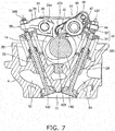
FIG. 6 , theintake valves exhaust valves cylinder head 4.FIG. 7 is a cross-sectional view of the interior of thecylinder head 4 as seen from the direction of the cam axis Ax3. As shown inFIG. 7 , thecylinder head 4 includes anintake port 31 and anexhaust port 32, both of which communicate with thecombustion chamber 11. - The
intake valves intake port 31. As shown inFIG. 6 , theintake valves first intake valve 27 and asecond intake valve 28. The first andsecond intake valves - As shown in
FIG. 4 , anintake valve spring 271 is attached to thefirst intake valve 27. Theintake valve spring 271 urges thefirst intake valve 27 in a direction to cause thefirst intake valve 27 to close theintake port 31. Likewise, anintake valve spring 281 is attached to thesecond intake valve 28, and urges thesecond intake valve 28 in a direction to cause thesecond intake valve 28 to close theintake port 31. - The
exhaust valves exhaust port 32. Theexhaust valves first exhaust valve 25 and asecond exhaust valve 26. The first andsecond exhaust valves - As shown in
FIG. 5 , anexhaust valve spring 251 is attached to thefirst exhaust valve 25. Theexhaust valve spring 251 urges thefirst exhaust valve 25 in a direction to cause thefirst exhaust valve 25 to close theexhaust port 32. Likewise, anexhaust valve spring 261 is attached to thesecond exhaust valve 26, and urges thesecond exhaust valve 26 in a direction to cause thesecond exhaust valve 26 to close theexhaust port 32. - As shown in
FIG. 7 , thevalve actuating mechanism 13 includes anexhaust rocker unit 33 and anintake rocker unit 34. Theexhaust rocker unit 33 is configured to open/close the first andsecond exhaust valves second exhaust valves intake rocker unit 34 is configured to open/close the first andsecond intake valves second intake valves exhaust rocker unit 33 and theintake rocker unit 34 are configured to be driven by thecamshaft 14. - The
exhaust rocker unit 33 includes anexhaust rocker shaft 35, anexhaust rocker arm 36 and a pressingmember 38. Theexhaust rocker shaft 35 is disposed in parallel to thecamshaft 14. Theexhaust rocker shaft 35 is supported by thecylinder head 4. When described in detail, theexhaust rocker shaft 35 is supported by the first and secondshaft support portions - The
exhaust rocker arm 36 is supported by theexhaust rocker shaft 35 and is thereby pivotable about theexhaust rocker shaft 35. Theexhaust rocker arm 36 is disposed to be capable of actuating theexhaust valves exhaust rocker arm 36 includes aroller 37 and anarm portion 39. - The
arm portion 39 is provided with a throughhole 364. Theexhaust roller shaft 35 is inserted into the throughhole 364. As shown inFIG. 6 , thearm portion 39 supports theroller 37 such that theroller 37 is rotatable. The rotational center axis of theroller 37 is arranged in parallel to the cam axis Ax3. Theroller 37 makes contact with theexhaust cam 146, and is configured to be rotated by rotation of theexhaust cam 146. - The pressing
member 38 is integrally provided on thearm portion 39. As shown inFIGS. 5 and6 , the pressingmember 38 is provided with first and second adjuster screws 365 and 366 on its tip. The tip of thefirst adjuster screw 365 faces the stem end of thefirst exhaust valve 25. As shown inFIG. 7 , the tip of thesecond adjuster screw 366 faces the stem end of thesecond exhaust valve 26. - When the
roller 37 is pressed and lifted up by theexhaust cam 146, theexhaust rocker arm 36 pivots. In conjunction with this, the pressingmember 38 downwardly presses the first andsecond exhaust valves exhaust port 32 is opened. On the other hand, when theroller 37 is not being pressed and lifted up by theexhaust cam 146, the first andsecond exhaust valves exhaust port 32 is closed. -
FIG. 8 is a perspective view of theintake rocker unit 34.FIG. 9 is a view of theintake rocker unit 34 as seen from a perpendicular direction to the cam axis Ax3. As shown inFIGS. 8 and9 , theintake rocker unit 34 includes anintake rocker shaft 41, afirst rocker arm 42, asecond rocker arm 43, a pressing member 44 (seeFIG. 6 ) and acoupling pin 45. Theintake rocker shaft 41 is disposed in parallel to thecamshaft 14. Theintake rocker shaft 41 is supported by thecylinder head 4. When described in detail, theintake rocker shaft 41 is supported by the first and secondshaft support portions - The
first rocker arm 42 is supported by theintake rocker shaft 41 and is thereby pivotable about theintake rocker shaft 41. Thefirst rocker arm 42 is disposed to be capable of actuating theintake valves FIG. 3 , thefirst rocker arm 42 includes afirst attachment portion 421. Thefirst attachment portion 421 is a hole provided in thefirst rocker arm 42. Theintake rocker shaft 41 is inserted into thefirst attachment portion 421. - The
first rocker arm 42 is provided with afirst coupling hole 422. Thefirst coupling hole 422 is located on the head cover side of theintake rocker shaft 41. Thefirst coupling hole 422 extends in the direction of the cam axis Ax3. Thecoupling pin 45 is inserted into thefirst coupling hole 422. - As shown in
FIG. 8 , thefirst rocker arm 42 includes afirst arm portion 420 and afirst contact portion 423. Thefirst contact portion 423 is mounted while being contactable with the firstintake cam portion 144. Thefirst contact portion 423 is a roller rotatably supported by thefirst arm portion 420. Thefirst contact portion 423 is configured to be rotated by rotation of the firstintake cam portion 144. The rotational center axis of thefirst contact portion 423 is arranged in parallel to the cam axis Ax3. When thefirst contact portion 423 makes contact with the firstintake cam portion 144, thefirst rocker arm 42 is configured to be rotated about the axis of theintake rocker shaft 41. - As shown in
FIG. 7 , thesecond rocker arm 43 is supported while being pivotable about theintake rocker shaft 41. Thesecond rocker arm 43 is disposed in alignment with thefirst rocker arm 42 in the direction of the cam axis Ax3. Thesecond rocker arm 43 is disposed on thecam chain chamber 16 side of thefirst rocker arm 42. As shown inFIG. 3 , thesecond rocker arm 43 includes asecond attachment portion 431. Thesecond attachment portion 431 is a hole provided in thesecond rocker arm 43. Theintake rocker shaft 41 is inserted into thesecond attachment portion 431. - The
second rocker arm 43 is provided with asecond coupling hole 432. Thesecond coupling hole 432 is located on the head cover side of theintake rocker shaft 41. Thesecond coupling hole 432 extends in the direction of the cam axis Ax3. Thesecond coupling hole 432 is disposed while overlapping with thefirst coupling hole 422 in the direction of the cam axis Ax3. Therefore, thecoupling pin 45 is insertable into thesecond coupling hole 432 of thesecond rocker arm 43. - As shown in
FIG. 8 , thesecond rocker arm 43 includes asecond arm portion 430 and asecond contact portion 433. Thesecond contact portion 433 is mounted in contact with the secondintake cam portion 145, and is capable of sliding against the secondintake cam portion 145. Thesecond arm portion 430 and thesecond contact portion 433 are integrally provided. Thesecond contact portion 433 has a shape of a slipper which is integrally provided on thesecond rocker arm 43. For example, thesecond contact portion 433 includes a hardened layer formed by surface finishing. The hardened layer has a higher hardness than the base material of which thesecond rocker arm 43 is made. The base material is, for instance, chromium molybdenum steel. The hardened layer is, for instance, DLC (diamond-like carbon). When thesecond contact portion 433 is slid against the secondintake cam portion 145, thesecond rocker arm 43 is configured to be rotated about the axis of theintake rocker shaft 41. - As shown in
FIG. 6 , the pressingmember 44 is connected to thefirst rocker arm 42. The pressingmember 44 is integrally provided on thefirst rocker arm 42. The pressingmember 44 is provided with first and second adjuster screws 441 and 442 on its tip. The tip of thefirst adjuster screw 441 faces the stem end of thefirst intake valve 27. The tip of thesecond adjuster screw 442 faces the stem end of thesecond intake valve 28. The pressingmember 44 is configured to be rotated about the axial direction of theintake rocker shaft 41, and is thereby configured to press the first andsecond intake valves - The
intake rocker unit 34 includes anarm urging member 46, afirst support member 47 and asecond support member 48. Thearm urging member 46 urges thesecond rocker arm 43 in a direction that thesecond contact portion 433 is pressed onto thecamshaft 14. In the present preferred embodiment, thearm urging member 46 is a coil spring through which theintake rocker shaft 41 is inserted. - The
first support member 47 supports an end of thearm urging member 46. Thefirst support member 47 has a shape of a pin and protrudes from thesecond rocker arm 43 in the direction of the cam axis Ax3. - The
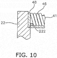
second support member 48 supports the other end of thearm urging member 46. Thesecond support member 48 is made of a bent plate material.FIG. 10 is a cross-sectional view of the secondshaft support portion 22, thearm urging member 46 and the vicinity thereof. As shown inFIG. 10 , the secondshaft support portion 22 is provided with astep 222, and thesecond support member 48 is supported by thestep 222. - As shown in
FIG. 3 , thecoupling pin 45 is mounted while being movable in the axial direction of thecamshaft 14. Thecoupling pin 45 is thus movable to a coupled position and a decoupled position. When moved to the coupled position, thecoupling pin 45 is disposed in both thefirst coupling hole 422 and thesecond coupling hole 432. Accordingly, thecoupling pin 45 is couple thefirst rocker arm 42 and thesecond rocker arm 43. In other words, when moved to the coupled position, thecoupling pin 45 couples the pressingmember 44 to thesecond rocker arm 43 through thefirst rocker arm 42. Accordingly, the pressingmember 44 pivots unitarily with the first andsecond rocker arms - When moved to the decoupled position, the
coupling pin 45 is disposed in thefirst coupling hole 422 without being disposed in thesecond coupling hole 432. Thus, when moved to the decoupled position, thecoupling pin 45 decouples thefirst rocker arm 42 and thesecond rocker arm 43 from each other. Specifically, when moved to the decoupled position, thecoupling pin 45 decouples thesecond rocker arm 43 from the pressingmember 44. Accordingly, the pressingmember 44 and thefirst rocker arm 42 pivot independently from thesecond rocker arm 43. - The
valve actuating mechanism 13 includes an opening andclosing timing changer 49. The opening andclosing timing changer 49 is configured to change the opening and closing timing of thefirst intake valve 27 and thesecond intake valve 28. The opening andclosing timing changer 49 is attached to thehead cover 5. - The opening and
closing timing changer 49 is an electromagnetic solenoid. When electrically supplied, the opening andclosing timing changer 49 presses thecoupling pin 45 in the axial direction of thecamshaft 14 whereby the position of thecoupling pin 45 is switched from the decoupled position to the coupled position. When the opening andclosing timing changer 49 is stopped being electrically supplied, the position of thecoupling pin 45 is returned to the decoupled position from the coupled position by elastic force of apin urging member 59 to be described. - The opening and
closing timing changer 49 includes arod 491 configured to press thecoupling pin 45 and abody 492 configured to drive therod 491. The center axis of therod 491 is arranged in parallel to the cam axis Ax3. Therod 491 is disposed while overlapping with thecoupling pin 45 in the pivot range of thecoupling pin 45 in a view seen from the direction of the cam axis Ax3. When driven by thebody 492, therod 491 presses thecoupling pin 45. - As shown in
FIG. 3 , theintake rocker unit 34 includes thepin urging member 59. Thepin urging member 59 is disposed inside thefirst coupling hole 422. Thepin urging member 59 urges thecoupling pin 45 in a direction from the coupled position to the decoupled position. Therefore, when thecoupling pin 45 is not being pressed by the opening andclosing timing changer 49, thecoupling pin 45 is kept in the decoupled position by thepin urging member 59. When thecoupling pin 45 is pressed by the opening andclosing timing changer 49, thecoupling pin 45 is moved from the decoupled position to the coupled position against the urging force of thepin urging member 59. -
FIG. 11 shows a condition that when thecoupling pin 45 is located in the coupled position, thesecond contact portion 433 is pressed and lifted up by the secondintake cam portion 145. When thecoupling pin 45 is located in the coupled position, thefirst rocker arm 42 is coupled to thesecond rocker arm 43 and unitarily pivot therewith. With this configuration, when thesecond contact portion 433 is pressed and lifted up by the secondintake cam portion 145, thesecond rocker arm 43 pivots about theintake rocker shaft 41. In conjunction with this, thefirst rocker arm 42 also pivots in a direction that the pressingmember 44 tilts down. - Accordingly, the tip of the
first adjuster screw 441 presses down thefirst intake valve 27, whereas the tip of thesecond adjuster screw 442 presses down thesecond intake valve 28. As a result, the first andsecond intake valves intake port 31. Thus, when thecoupling pin 45 is located in the coupled position, the pressingmember 44 presses the first andsecond intake valves second rocker arm 43. When thesecond contact portion 433 is not being pressed and lifted up by the secondintake cam portion 145, the first andsecond intake valves intake port 31 is closed. - When the
coupling pin 45 is located in the decoupled position, thefirst rocker arm 42 pivots independently from thesecond rocker arm 43. With this configuration, when thefirst contact portion 423 is pressed and lifted up by the firstintake cam portion 144, thefirst rocker arm 42 is pivots about theintake rocker shaft 41 in a direction that the pressingmember 44 tilts down. - Accordingly, the tip of the
first adjuster screw 441 presses down thefirst intake valve 27, whereas the tip of thesecond adjuster screw 442 presses down thesecond intake valve 28. As a result, the first andsecond intake valves intake port 31. Thus, when thecoupling pin 45 is located in the decoupled position, the pressingmember 44 presses the first andsecond intake valves first rocker arm 42. When thefirst contact portion 423 is not being pressed and lifted up by the firstintake cam portion 144, the first andsecond intake valves intake port 31 is closed. - It should be noted that the shapes of the first and second
intake cam portions intake cam portion 145 presses and lift up thesecond contact portion 433 before the tip of the firstintake cam portion 144 reaches thefirst contact portion 423. With this construction, when thecoupling pin 45 is located in the coupled position, thefirst rocker arm 42 is actuated by rotation of the secondintake cam portion 145. Accordingly, rotation of the firstintake cam portion 144 is not transmitted to thefirst rocker arm 42. - Therefore, when the
coupling pin 45 is located in the coupled position, the first andsecond intake valves intake cam portion 145. On the other hand, when thecoupling pin 45 is located in the decoupled position, rotation of the secondintake cam portion 145 is not transmitted to thefirst rocker arm 42. Therefore, when thecoupling pin 45 is located in the decoupled position, the first andsecond intake valves intake cam portion 144. - Next, the construction of the
intake rocker shaft 41 will be explained in detail.FIG. 12 is a perspective view of theintake rocker shaft 41. As shown inFIG. 12 , theintake rocker shaft 41 includes ashaft member 51 and acollar member 52. Theshaft member 51 and thecollar member 52 are provided as separate members. Thecollar member 52 has a shape of a tube. Theshaft member 51 is inserted into ahole 521 of thecollar member 52. Theshaft member 51 is not fixed to thecollar member 52. Therefore, thecollar member 52 is rotatable relatively to theshaft member 51. - The
shaft member 51 includes afirst end 511 and asecond end 512. Thefirst end 511 is one end of theshaft member 51 in the axial direction of theintake rocker shaft 41. Thesecond end 512 is the other end of theshaft member 51 in the axial direction of theintake rocker shaft 41. Thefirst end 511 protrudes from thecollar member 52 to one side in the axial direction of theintake rocker shaft 41. Thesecond end 512 protrudes from thecollar member 52 to the other side in the axial direction of theintake rocker shaft 41. - As shown in
FIG. 3 , thefirst end 511 is supported by the firstshaft support portion 21. The firstshaft support portion 21 is provided with a firstrocker shaft hole 212. The firstrocker shaft hole 212 is disposed adjacently to thefirst camshaft hole 211. The firstrocker shaft hole 212 penetrates the firstshaft support portion 21 in the direction of the cam axis Ax3. Thefirst end 511 is inserted into the firstrocker shaft hole 212. The end surface of thefirst end 511 is disposed to face thecam chain chamber 16. - The
second end 512 is supported by the secondshaft support portion 22. The secondshaft support portion 22 is provided with a secondrocker shaft hole 223. The secondrocker shaft hole 223 is disposed adjacently to thesecond camshaft hole 221. The secondrocker shaft hole 223 does not penetrate the secondshaft support portion 22. It should be noted that the secondrocker shaft hole 223 may penetrate the secondshaft support portion 22. Thesecond end 512 is inserted into the secondrocker shaft hole 223. - As shown in
FIG. 8 , a boundary B between thefirst coupling hole 422 of thefirst rocker arm 42 and thesecond coupling hole 432 of thesecond rocker arm 43 is located closer to thesecond end 512 than a middle position M located in the middle of an interval L between thefirst end 511 and thesecond end 512. When described in more detail, a distance L2 from the boundary B to thesecond end 512 is shorter than a distance L1 from the boundary B to the first end 511 (L2<L1). - As shown in
FIG. 12 , thefirst end 511 is provided with alock groove 513 on its end surface. When a tool is locked to thelock groove 513, theshaft member 51 is attachable to or detachable from the firstrocker shaft hole 212 by operating the tool. - The
second end 512 is provided with alock hole 514. Thelock hole 514 penetrates thesecond end 512 in a perpendicular direction to the axis of theshaft member 51. As shown inFIG. 5 , the secondshaft support portion 22 is provided with a hole 224 extending perpendicularly to the axial direction of the secondrocker shaft hole 223. The hole 224 is opened on the top surface of the secondshaft support portion 22. Afastener member 53 shown inFIG. 6 is inserted into the hole 224 of the secondshaft support portion 22 and thelock hole 514 of thesecond end 512. Accordingly, theshaft member 51 is prevented from being detached from the secondshaft support portion 22. - The
collar member 52 is provided separately from theshaft member 51. Thecollar member 52 is disposed between thefirst end 511 and thesecond end 512 in the axial direction of theintake rocker shaft 41. Thecollar member 52 is disposed between the firstshaft support portion 21 and the secondshaft support portion 22. The first andsecond rocker arms collar member 52. In other words, thecollar member 52 is inserted into thefirst attachment portion 421 of thefirst rocker arm 42 and thesecond attachment portion 431 of thesecond rocker arm 43. Thearm urging member 46 and thesecond support member 48 are also attached to thecollar member 52. - The outer diameter of the
collar member 52 is larger than that of theshaft member 51. The outer diameter of thecollar member 52 is larger than that of theexhaust rocker shaft 35. The outer diameter of thecollar member 52 is larger than that of thefirst end 511 and is also larger than that of thesecond end 512. The inner diameter of the firstrocker shaft hole 212 is smaller than the outer diameter of thecollar member 52. The inner diameter of the secondrocker shaft hole 223 is smaller than the outer diameter of thecollar member 52. - In the
engine 1 according to the present preferred embodiment described above, the outer diameter of thecollar member 52 to which the first andsecond rocker arms first end 511 of theshaft member 51 and is also larger than that of thesecond end 512 of theshaft member 51. With this construction, theintake rocker unit 34 can be enhanced in stiffness of coupling, and simultaneously, increase in inertia mass can be inhibited. - Additionally, the outer diameter of the
first end 511 is smaller than that of thecollar member 52. - With this construction, enlargement of the first
rocker shaft hole 212 in the firstshaft support portion 21 can be inhibited. - As described above, the first
rocker shaft hole 212 is disposed adjacently to thefirst camshaft hole 211. Therefore, when the firstrocker shaft hole 212 is constructed to have a large outer diameter, it is concerned that the thickness of a portion between the firstrocker shaft hole 212 and thefirst camshaft hole 211 becomes thin and this results in crack formation in the firstshaft support portion 21. To cope with this concern, it can be assumed that the portion between the firstrocker shaft hole 212 and thefirst camshaft hole 211 is constructed to have a large thickness while the firstrocker shaft hole 212 is constructed to have a large outer diameter. In this case, however, it is inevitable that the firstshaft support portion 21 is entirely enlarged. It is thus concerned that thecylinder head 4 is increased in size. - By contrast, in the present preferred embodiment, enlargement of the first
rocker shaft hole 212 can be inhibited by the aforementioned construction of theintake rocker shaft 41. Therefore, crack formation in the firstshaft support portion 21 can be inhibited, and simultaneously, increase in size of thecylinder head 4 can be inhibited. - Similarly to the outer diameter of the
first end 511, the outer diameter of thesecond end 512 is smaller than that of thecollar member 52. Hence, enlargement of the secondrocker shaft hole 223 of the secondshaft support portion 22 can be inhibited. Therefore, crack formation in the secondshaft support portion 22 can be inhibited, and simultaneously, increase in size of thecylinder head 4 can be inhibited. - Additionally, in the present preferred embodiment, the first
shaft support portion 21 protrudes to the head cover side further than thesidewall end 4b. With this construction, the head cover side end 21 a of the firstshaft support portion 21 is not supported by the other portion of thecylinder head 4. In other words, the head cover side end 21 a is a free end. -
FIGS. 13 and14 show thecylinder head 4 according to a first modification. In thecylinder head 4 according to the first modification, thesidewall end 4b is located on the further head cover side than that of the aforementioned preferred embodiment such that theend 21a of the firstshaft support portion 21 and thesidewall end 4b are located in the same position in the cylinder axial direction. In the first modification, theend 21 a of the firstshaft support portion 21 can be connected to and supported by thesidewall 4a of thecylinder head 4. Therefore, the firstshaft support portion 21 has high stiffness. - By contrast, as with the aforementioned exemplary embodiment, when the first
shaft support portion 21 protrudes to the head cover side further than thesidewall end 4b, theend 21a of the firstshaft support portion 21 is supported by thecylinder head 4 in a cantilevered manner. Therefore, the protruding portion of the firstshaft support portion 21 has low stiffness, and large stress is likely to act on the firstshaft support portion 21 in running theengine 1. - In the aforementioned preferred embodiment, even in this construction, enlargement of the first
rocker shaft hole 212 can be inhibited by using thecollar member 52. Accordingly, crack formation in the firstshaft support portion 21 can be sufficiently inhibited. - Additionally in the aforementioned preferred embodiment, the second
shaft support portion 22 protrudes to the head cover side further than thesidewall end 4b. Hence, similarly to the firstshaft support portion 21, the secondshaft support portion 22 has low stiffness, and large stress is likely to act on the secondshaft support portion 22 in running theengine 1. However, even in this construction, enlargement of the secondrocker shaft hole 223 can be inhibited by using thecollar member 52. Accordingly, crack formation in the secondshaft support portion 22 can be sufficiently inhibited. - Additionally, as shown in
FIG. 15 , there are chances of occurrence of bending deformation of theshaft member 51 at the boundary B between thefirst rocker arm 42 and thesecond rocker arm 43. For example, the extent of such deformation becomes large when the engine speed becomes high while thefirst rocker arm 42 and thesecond rocker arm 43 are not coupled to each other due to breakdown of the opening andclosing timing changer 49, bending-related damage of thecoupling pin 45, or so forth. As with the aforementioned preferred embodiment, when the position of the boundary B is located closer to the secondshaft support portion 22 than to the firstshaft support portion 21, the extent of bending deformation becomes large in a close position to the secondshaft support portion 22. In this case, there are chances that large stress acts on the secondshaft support portion 22. Even in this case, large stiffness of coupling is obtainable by attaching thecollar member 52 to theshaft member 51. Hence, the extent of bending deformation can be reduced compared to a construction that thecollar member 52 is not attached to theshaft member 51. Accordingly, stress acting on the secondshaft support portion 22 can be inhibited low. It should be noted that deformation similarly occurs even when the position of the boundary B is located in the middle position M. In this case, stress acting on the secondshaft support portion 22 becomes smaller than that in the aforementioned preferred embodiment. It is still obvious that stress inhibiting effect can be obtained by thecollar member 52. - Moreover, the
collar member 52 and theshaft member 51 are provided as separate members, and theshaft member 51 is inserted into thehole 521 of thecollar member 52. With this construction, in assembling theengine 1, theintake rocker shaft 41 can be attached to the first and secondshaft support portions shaft member 51 to the first and second rocker shaft holes 212 and 223 without inserting thecollar member 52 thereto. Consequently, good assembling performance can be reliably achieved while enlargement of the first and second rocker shaft holes 212 and 223 can be inhibited. - Additionally, the
first rocker arm 42 includes the roller as thefirst contact portion 423, whereas thesecond rocker arm 43 includes the slipper as thesecond contact portion 433. With the roller provided as thefirst contact portion 423, drive loss with respect to the rocker shaft corresponding to a low speed range can be more reduced than when thefirst contact portion 423 has a slipper and is processed with surface finishing. On the other hand, with thesecond contact portion 433 has the slipper, inertia mass, exerting a great impact in a high speed range, can be more reduced than when a roller is provided as thesecond contact portion 433, and simultaneously, drive loss can be inhibited equivalently to when the roller is provided as thesecond contact portion 433. - One preferred embodiment of the present invention has been explained above. However, the present invention is not limited to the aforementioned preferred embodiment, and a variety of changes can be made without departing from the scope of the present invention.
- The engine is not limited to a single-cylinder engine of a water cooling type. For example, the engine may be of an air cooling type. The engine may be a multiple-cylinder engine.
- The number of exhaust valves is not limited to two, and alternatively, may be one or may be three or greater. The number of intake valves is not limited to two, and alternatively, may be one or may be three or greater.
- The construction and positional arrangement of the
valve actuating mechanism 13 may be changed. For example, thefirst contact portion 423 may be a slipper which is integrally provided on thefirst rocker arm 42. In other words, each of the first andsecond contact portions FIG. 16 related to a second modification, thefirst contact portion 423 may be a first roller rotatably supported by thefirst arm portion 420, whereas thesecond contact portion 433 may be a second roller rotatably supported by thesecond arm portion 430. - In the aforementioned preferred embodiment, the mechanism configured to switch the timing of opening and closing valves by the opening and
closing timing changer 49 is applied to the intake valves. However, this mechanism may be applied to the exhaust valves. The rocker shaft structure including theshaft member 51 and thecollar member 52 may be applied to the exhaust rocker shaft. - The
collar member 52 may be non-rotatably attached to theshaft member 51. - As shown in
FIG. 17 related to a third modification, the pressingmember 44 may be provided separately from the first andsecond rocker arms aforementioned coupling pin 45 is located in the coupled position, thesecond rocker arm 43 and the pressingmember 44 may be coupled by thecoupling pin 45. On the other hand, when thecoupling pin 45 is located in the decoupled position, thefirst rocker arm 42 and the pressingmember 44 may be coupled by thecoupling pin 45. - The
coupling pin 45 may be configured to be driven by a hydraulic pump (opening and closing timing changer). For example, in a fourth modification shown inFIG. 18 , thefirst rocker arm 42 is provided with a first oil chamber 42r and anoil channel 42m. Oil in the first oil chamber 42r can be compressed and decompressed through theoil channel 42m. Likewise, thesecond rocker arm 43 is provided with asecond oil chamber 43r and anoil channel 43m. Oil in thesecond oil chamber 43r can be compressed and decompressed through theoil channel 43m. The pressingmember 44 is provided with apin hole 45r. Thepin hole 45r communicates with the first andsecond oil chambers 42r and 43r. Thepin hole 45r accommodates thecoupling pin 45. With this construction, in conjunction with displacement of thecoupling pin 45 by hydraulic pressure, the pressingmember 44 can be selectively coupled to either thefirst rocker arm 42 or thesecond rocker arm 43. - As shown in
FIG. 19 related to a fifth modification, the first andsecond rocker arms pressing members first rocker arm 42 may be provided with a first pressingmember 44a, whereas thesecond rocker arm 43 may be provided with a secondpressing member 44b. In this construction, when thecoupling pin 45 is located in the decoupled position, the first pressingmember 44a, provided on thefirst rocker arm 42, preferably presses thefirst intake valve 27 in conjunction with rotation of thefirst rocker arm 42. On the other hand, when thecoupling pin 45 is located in the coupled position, the second pressingmember 44b, provided on thesecond rocker arm 43, preferably presses thesecond intake valve 28 in conjunction with rotation of thesecond rocker arm 43. - As shown in
FIGS. 13 and14 , at least portion of thesidewall end 4b may be located in the same position as at least one of theend 21a of the firstshaft support portion 21 and theend 22a of the secondshaft support portion 22 in the cylinder axial direction. It should be noted that theend 21a of the firstshaft support portion 21 and theend 22a of the secondshaft support portion 22 may be located in different positions in the cylinder axial direction.
Claims (14)
- An engine (1), comprising:a cylinder head (4);a valve (25,26,27,28) attached to the cylinder head (4);a rocker unit (33, 34) configured to open/close the valve (25,26,27,28) by pressing the valve (25, 26, 27,28);a camshaft (14) configured to drive the rocker unit (33, 34);an opening and closing timing changer (49) configured to change timing of opening and closing the valve (25,26,27,28), whereinthe rocker unit (33, 34) includesa rocker shaft (35,41) supported by the cylinder head (4),a first rocker arm (42) including a first attachment portion (421) and a first contact portion (423), the first attachment portion (421) being attached to the rocker shaft (35,41), the first contact portion (423) being connected to the first attachment portion (421), the first contact portion (423) being mounted to be contactable with the camshaft (14), the first rocker arm (42) being configured to be rotated about an axis of the rocker shaft (35, 41) when the first contact portion (423) makes contact with the camshaft (14),a second rocker arm (43) including a second attachment portion (431) and a second contact portion (433), the second attachment portion (431) being attached to the rocker shaft (35, 41), the second contact portion (433) being connected to the second attachment portion (431), the second contact portion (433) being mounted to be contactable with the camshaft (14), the second rocker arm (43) being disposed in alignment with the first rocker arm (42) in a direction of the axis of the rocker shaft (35,41), the second rocker arm (43) being configured to be rotated about the axis of the rocker shaft (35,41) when the second contact portion (433) makes contact with the camshaft (14),a pressing member (38, 44) configured to press the valve (25,26,27,28) by rotating about the axis of the rocker shaft (35, 41),anda coupling pin (45) mounted to be movable to a coupled position and a decoupled position by the opening and closing timing changer (49), the coupling pin (45) being configured to couple the second rocker arm (43) to the pressing member (38, 44) when the coupling pin (45) is located in the coupled position, the coupling pin (45) being configured to decouple the second rocker arm (43) from the pressing member (38, 44) when the coupling pin (45) is located in the decoupled position,the pressing member (38, 44) is configured to press the valve (25, 26, 27, 28) in conjunction with rotation of the first rocker arm (42) when the coupling pin (45) is located in the decoupled position, the pressing member (38, 44) being configured to press the valve (25, 26, 27, 28) in conjunction with rotation of the second rocker arm (43) when the coupling pin (45) is located in the coupled position,the cylinder head (4) includes a first shaft support portion (21) and a second shaft support portion (22),the first (21) and second (22) shaft support portions supporting the rocker shaft (35, 41),the rocker shaft (35, 41) includesa shaft member (51) including a first end (511) and a second end (512), the first end (511) being one end of the shaft member (51) in the direction of the axis of the rocker shaft (35,41), the first end (511) being supported by the first shaft support portion (21), the second end (512) being the other end of the shaft member (51) in the direction of the axis of the rocker shaft (35, 41), the second end (512) being supported by the second shaft support portion (22), anda collar member (52) provided separately from the shaft member (51), the collar member (52) being disposed between the first end (511) and the second end (512) in the direction of the axis of the rocker shaft (35,41),the first (42) and second (43) rocker arms are attached to the collar member (52),the collar member (52) has an outer diameter larger than each of an outer diameter of the first end (511) and an outer diameter of the second end (512), andthe shaft member (51) is inserted into a hole (521) provided in the collar member (52).
- The engine (1) according to claim 1, wherein the collar member (52) is rotatable relatively to the shaft member (51).
- The engine (1) according to claim 1 or 2, wherein the first shaft support portion (21) includes a rocker shaft hole (212) into which the first end (511) is inserted, and a camshaft hole (211, 221) into which the camshaft (14) is inserted, the camshaft hole (221) being disposed adjacently to the rocker shaft hole (212).
- The engine (1) according to claim 3, wherein the rocker shaft hole(212) has an inner diameter smaller than the outer diameter of the collar member (52).
- The engine (1) according to any of claims 1 to 4, wherein the pressing member (38, 44) is integrally provided on the first rocker arm (42).
- The engine (1) according to any of claims 1 to 5, further comprising:an urging member (59) for urging the coupling pin (45).
- The engine (1) according to any of claims 1 to 6, wherein the first contact portion (423) has a shape of a slipper integrally provided on the first rocker arm (42).
- The engine (1) according to any of claims 1 to 7, wherein the second contact portion (433) has a shape of a slipper integrally provided on the second rocker arm (43).
- The engine (1) according to any of claims 1 to 6, wherein the first rocker arm (42) includes a first arm portion (420) supporting the first contact portion (423), the first contact portion (423) is a first roller rotatably supported by the first arm portion (420), the second rocker arm (43) includes a second arm portion (430) supporting the second contact portion (433), and the second contact portion (433) is a second roller rotatably supported by the second arm portion (430).
- The engine (1) according to any of claims 1 to 6, wherein the first rocker arm (42) includes a first arm portion (420) supporting the first contact portion (423), the first contact portion (423) is a first roller rotatably supported by the first arm portion (420), and the second contact portion (433) is a slipper integrally provided on the second rocker arm (43).
- The engine (1) according to any of claims 1 to 10, further comprising:a head cover (5) attached to the cylinder head (4), wherein the cylinder head (4) includes a sidewall end (4b) abutted to the head cover (5), and the first shaft support portion (21) protrudes to a head cover side further than the sidewall end (4b).
- The engine (1) according to any of claims 1 to 11, wherein a boundary (B) between the first rocker arm (42) and the second rocker arm (43) is disposed closer to either the first shaft support portion (21) or the second shaft support portion (22) than a middle position (M) between the first shaft support portion (21) and the second shaft support portion (22).
- The engine (1) according to any of claims 1 to 12, wherein the engine (1) is a single-cylinder engine.
- A straddled vehicle (100), comprising:the engine (1) recited in any of claims 1 to 13.
Applications Claiming Priority (1)
| Application Number | Priority Date | Filing Date | Title |
|---|---|---|---|
| JP2015203543A JP2018197498A (en) | 2015-10-15 | 2015-10-15 | Saddle-type vehicle engine |
Publications (2)
| Publication Number | Publication Date |
|---|---|
| EP3156618A1 true EP3156618A1 (en) | 2017-04-19 |
| EP3156618B1 EP3156618B1 (en) | 2018-06-13 |
Family
ID=57003435
Family Applications (2)
| Application Number | Title | Priority Date | Filing Date |
|---|---|---|---|
| EP16190756.3A Active EP3156618B1 (en) | 2015-10-15 | 2016-09-27 | Engine |
| EP16831610.7A Active EP3363999B1 (en) | 2015-10-15 | 2016-10-12 | Engine |
Family Applications After (1)
| Application Number | Title | Priority Date | Filing Date |
|---|---|---|---|
| EP16831610.7A Active EP3363999B1 (en) | 2015-10-15 | 2016-10-12 | Engine |
Country Status (6)
| Country | Link |
|---|---|
| EP (2) | EP3156618B1 (en) |
| JP (1) | JP2018197498A (en) |
| BR (1) | BR112017003899B1 (en) |
| ES (1) | ES2675287T3 (en) |
| TW (2) | TWI626366B (en) |
| WO (1) | WO2017065168A1 (en) |
Families Citing this family (3)
| Publication number | Priority date | Publication date | Assignee | Title |
|---|---|---|---|---|
| IT202200002711A1 (en) * | 2022-02-15 | 2023-08-15 | Piaggio & C Spa | SYSTEM FOR VARIATION OF THE OPENING AND/OR CLOSING PHASE OF INTAKE VALVES |
| JP7831203B2 (en) * | 2022-09-06 | 2026-03-17 | スズキ株式会社 | Variable valve timing system |
| JP7841396B2 (en) * | 2022-09-07 | 2026-04-07 | スズキ株式会社 | Variable valve timing system |
Citations (3)
| Publication number | Priority date | Publication date | Assignee | Title |
|---|---|---|---|---|
| JPS6030406A (en) * | 1983-07-29 | 1985-02-16 | Honda Motor Co Ltd | Device for forcibly opening and closing valve in internal-combustion engine |
| US5241928A (en) * | 1992-03-13 | 1993-09-07 | Suzuki Motor Corp. | Movable valve device for engine |
| JP2015010552A (en) | 2013-06-28 | 2015-01-19 | ヤマハ発動機株式会社 | Engine |
Family Cites Families (6)
| Publication number | Priority date | Publication date | Assignee | Title |
|---|---|---|---|---|
| JPS61250314A (en) * | 1985-04-26 | 1986-11-07 | Mazda Motor Corp | Valve tappet device for engine |
| JP2577577B2 (en) * | 1987-10-21 | 1997-02-05 | マツダ株式会社 | Engine valve control device |
| JPH05311233A (en) * | 1992-05-07 | 1993-11-22 | Hino Motors Ltd | Cast iron parts having excellent wear resistance and scuffing resistance |
| JP3972640B2 (en) * | 2001-11-27 | 2007-09-05 | 三菱自動車工業株式会社 | Cylinder head structure and assembly method thereof |
| JP2015010554A (en) | 2013-06-28 | 2015-01-19 | ヤマハ発動機株式会社 | Engine |
| ES2572254T3 (en) * | 2013-09-30 | 2016-05-31 | Honda Motor Co Ltd | Variable internal combustion engine valve gear for astride type vehicle |
-
2015
- 2015-10-15 JP JP2015203543A patent/JP2018197498A/en active Pending
-
2016
- 2016-09-27 EP EP16190756.3A patent/EP3156618B1/en active Active
- 2016-09-27 ES ES16190756.3T patent/ES2675287T3/en active Active
- 2016-10-06 TW TW105132340A patent/TWI626366B/en active
- 2016-10-12 BR BR112017003899-4A patent/BR112017003899B1/en active IP Right Grant
- 2016-10-12 EP EP16831610.7A patent/EP3363999B1/en active Active
- 2016-10-12 WO PCT/JP2016/080242 patent/WO2017065168A1/en not_active Ceased
-
2017
- 2017-02-24 TW TW106106361A patent/TWI652403B/en active
Patent Citations (3)
| Publication number | Priority date | Publication date | Assignee | Title |
|---|---|---|---|---|
| JPS6030406A (en) * | 1983-07-29 | 1985-02-16 | Honda Motor Co Ltd | Device for forcibly opening and closing valve in internal-combustion engine |
| US5241928A (en) * | 1992-03-13 | 1993-09-07 | Suzuki Motor Corp. | Movable valve device for engine |
| JP2015010552A (en) | 2013-06-28 | 2015-01-19 | ヤマハ発動機株式会社 | Engine |
Also Published As
| Publication number | Publication date |
|---|---|
| EP3363999A4 (en) | 2019-06-05 |
| EP3363999A1 (en) | 2018-08-22 |
| EP3363999B1 (en) | 2021-12-29 |
| BR112017003899A2 (en) | 2017-12-05 |
| BR112017003899B1 (en) | 2023-01-17 |
| TW201814146A (en) | 2018-04-16 |
| TWI652403B (en) | 2019-03-01 |
| EP3156618B1 (en) | 2018-06-13 |
| TWI626366B (en) | 2018-06-11 |
| ES2675287T3 (en) | 2018-07-10 |
| TW201713846A (en) | 2017-04-16 |
| WO2017065168A1 (en) | 2017-04-20 |
| JP2018197498A (en) | 2018-12-13 |
Similar Documents
| Publication | Publication Date | Title |
|---|---|---|
| US7854215B2 (en) | Valve train with overload features | |
| KR101036533B1 (en) | Decompression device of the engine | |
| EP3156618B1 (en) | Engine | |
| US5060605A (en) | Valve drive mechanism for vehicle engine | |
| JP2010151118A (en) | Fixing structure of valve system rotation shaft for internal combustion engine | |
| JP4361772B2 (en) | Four-cycle engine valve gear | |
| US7934476B2 (en) | Valve-actuating system for an internal combustion engine, engine incorporating same, and method of using same | |
| US20130042830A1 (en) | Valve operating apparatus for internal combustion engine | |
| US7252058B2 (en) | Lift-variable valve-operating system for internal combustion engine | |
| JP4603213B2 (en) | Solenoid valve device | |
| EP0324092B1 (en) | Valve actuation device for multi-valve-type engine | |
| EP3495633B1 (en) | Engine | |
| JP5189520B2 (en) | High pressure pump mounting structure for internal combustion engine | |
| JP4117481B2 (en) | Variable valve operating device for internal combustion engine | |
| JP4866328B2 (en) | Variable valve mechanism | |
| US7918201B2 (en) | Variable valve mechanism for engine | |
| JP4063960B2 (en) | Valve mechanism of multi-cylinder engine | |
| JP4474075B2 (en) | Variable lift valve gear | |
| EP3842623B1 (en) | Lost motion mechanism, valve gear and engine | |
| JP4123372B2 (en) | Variable valve operating device for internal combustion engine | |
| JP4818333B2 (en) | Four-cycle engine valve gear | |
| JP2011202577A (en) | Variable valve gear for engine | |
| JP2010190082A (en) | High pressure pump driving structure for internal combustion engine | |
| JP2010038095A (en) | Engine valve gear | |
| JP3661431B2 (en) | Swing follower mechanism for 3D cam |
Legal Events
| Date | Code | Title | Description |
|---|---|---|---|
| PUAI | Public reference made under article 153(3) epc to a published international application that has entered the european phase |
Free format text: ORIGINAL CODE: 0009012 |
|
| 17P | Request for examination filed |
Effective date: 20160927 |
|
| AK | Designated contracting states |
Kind code of ref document: A1 Designated state(s): AL AT BE BG CH CY CZ DE DK EE ES FI FR GB GR HR HU IE IS IT LI LT LU LV MC MK MT NL NO PL PT RO RS SE SI SK SM TR |
|
| AX | Request for extension of the european patent |
Extension state: BA ME |
|
| RBV | Designated contracting states (corrected) |
Designated state(s): AL AT BE BG CH CY CZ DE DK EE ES FI FR GB GR HR HU IE IS IT LI LT LU LV MC MK MT NL NO PL PT RO RS SE SI SK SM TR |
|
| GRAP | Despatch of communication of intention to grant a patent |
Free format text: ORIGINAL CODE: EPIDOSNIGR1 |
|
| INTG | Intention to grant announced |
Effective date: 20180214 |
|
| GRAS | Grant fee paid |
Free format text: ORIGINAL CODE: EPIDOSNIGR3 |
|
| GRAA | (expected) grant |
Free format text: ORIGINAL CODE: 0009210 |
|
| AK | Designated contracting states |
Kind code of ref document: B1 Designated state(s): AL AT BE BG CH CY CZ DE DK EE ES FI FR GB GR HR HU IE IS IT LI LT LU LV MC MK MT NL NO PL PT RO RS SE SI SK SM TR |
|
| REG | Reference to a national code |
Ref country code: GB Ref legal event code: FG4D |
|
| REG | Reference to a national code |
Ref country code: CH Ref legal event code: EP Ref country code: AT Ref legal event code: REF Ref document number: 1008723 Country of ref document: AT Kind code of ref document: T Effective date: 20180615 |
|
| REG | Reference to a national code |
Ref country code: ES Ref legal event code: FG2A Ref document number: 2675287 Country of ref document: ES Kind code of ref document: T3 Effective date: 20180710 |
|
| REG | Reference to a national code |
Ref country code: IE Ref legal event code: FG4D |
|
| REG | Reference to a national code |
Ref country code: DE Ref legal event code: R096 Ref document number: 602016003555 Country of ref document: DE |
|
| REG | Reference to a national code |
Ref country code: FR Ref legal event code: PLFP Year of fee payment: 3 |
|
| REG | Reference to a national code |
Ref country code: NL Ref legal event code: MP Effective date: 20180613 |
|
| REG | Reference to a national code |
Ref country code: LT Ref legal event code: MG4D |
|
| PG25 | Lapsed in a contracting state [announced via postgrant information from national office to epo] |
Ref country code: LT Free format text: LAPSE BECAUSE OF FAILURE TO SUBMIT A TRANSLATION OF THE DESCRIPTION OR TO PAY THE FEE WITHIN THE PRESCRIBED TIME-LIMIT Effective date: 20180613 Ref country code: CY Free format text: LAPSE BECAUSE OF FAILURE TO SUBMIT A TRANSLATION OF THE DESCRIPTION OR TO PAY THE FEE WITHIN THE PRESCRIBED TIME-LIMIT Effective date: 20180613 Ref country code: FI Free format text: LAPSE BECAUSE OF FAILURE TO SUBMIT A TRANSLATION OF THE DESCRIPTION OR TO PAY THE FEE WITHIN THE PRESCRIBED TIME-LIMIT Effective date: 20180613 Ref country code: NO Free format text: LAPSE BECAUSE OF FAILURE TO SUBMIT A TRANSLATION OF THE DESCRIPTION OR TO PAY THE FEE WITHIN THE PRESCRIBED TIME-LIMIT Effective date: 20180913 Ref country code: BG Free format text: LAPSE BECAUSE OF FAILURE TO SUBMIT A TRANSLATION OF THE DESCRIPTION OR TO PAY THE FEE WITHIN THE PRESCRIBED TIME-LIMIT Effective date: 20180913 Ref country code: SE Free format text: LAPSE BECAUSE OF FAILURE TO SUBMIT A TRANSLATION OF THE DESCRIPTION OR TO PAY THE FEE WITHIN THE PRESCRIBED TIME-LIMIT Effective date: 20180613 |
|
| PG25 | Lapsed in a contracting state [announced via postgrant information from national office to epo] |
Ref country code: GR Free format text: LAPSE BECAUSE OF FAILURE TO SUBMIT A TRANSLATION OF THE DESCRIPTION OR TO PAY THE FEE WITHIN THE PRESCRIBED TIME-LIMIT Effective date: 20180914 Ref country code: HR Free format text: LAPSE BECAUSE OF FAILURE TO SUBMIT A TRANSLATION OF THE DESCRIPTION OR TO PAY THE FEE WITHIN THE PRESCRIBED TIME-LIMIT Effective date: 20180613 Ref country code: LV Free format text: LAPSE BECAUSE OF FAILURE TO SUBMIT A TRANSLATION OF THE DESCRIPTION OR TO PAY THE FEE WITHIN THE PRESCRIBED TIME-LIMIT Effective date: 20180613 Ref country code: RS Free format text: LAPSE BECAUSE OF FAILURE TO SUBMIT A TRANSLATION OF THE DESCRIPTION OR TO PAY THE FEE WITHIN THE PRESCRIBED TIME-LIMIT Effective date: 20180613 |
|
| REG | Reference to a national code |
Ref country code: AT Ref legal event code: MK05 Ref document number: 1008723 Country of ref document: AT Kind code of ref document: T Effective date: 20180613 |
|
| PG25 | Lapsed in a contracting state [announced via postgrant information from national office to epo] |
Ref country code: NL Free format text: LAPSE BECAUSE OF FAILURE TO SUBMIT A TRANSLATION OF THE DESCRIPTION OR TO PAY THE FEE WITHIN THE PRESCRIBED TIME-LIMIT Effective date: 20180613 |
|
| PG25 | Lapsed in a contracting state [announced via postgrant information from national office to epo] |
Ref country code: EE Free format text: LAPSE BECAUSE OF FAILURE TO SUBMIT A TRANSLATION OF THE DESCRIPTION OR TO PAY THE FEE WITHIN THE PRESCRIBED TIME-LIMIT Effective date: 20180613 Ref country code: CZ Free format text: LAPSE BECAUSE OF FAILURE TO SUBMIT A TRANSLATION OF THE DESCRIPTION OR TO PAY THE FEE WITHIN THE PRESCRIBED TIME-LIMIT Effective date: 20180613 Ref country code: IS Free format text: LAPSE BECAUSE OF FAILURE TO SUBMIT A TRANSLATION OF THE DESCRIPTION OR TO PAY THE FEE WITHIN THE PRESCRIBED TIME-LIMIT Effective date: 20181013 Ref country code: AT Free format text: LAPSE BECAUSE OF FAILURE TO SUBMIT A TRANSLATION OF THE DESCRIPTION OR TO PAY THE FEE WITHIN THE PRESCRIBED TIME-LIMIT Effective date: 20180613 Ref country code: SK Free format text: LAPSE BECAUSE OF FAILURE TO SUBMIT A TRANSLATION OF THE DESCRIPTION OR TO PAY THE FEE WITHIN THE PRESCRIBED TIME-LIMIT Effective date: 20180613 Ref country code: RO Free format text: LAPSE BECAUSE OF FAILURE TO SUBMIT A TRANSLATION OF THE DESCRIPTION OR TO PAY THE FEE WITHIN THE PRESCRIBED TIME-LIMIT Effective date: 20180613 Ref country code: PL Free format text: LAPSE BECAUSE OF FAILURE TO SUBMIT A TRANSLATION OF THE DESCRIPTION OR TO PAY THE FEE WITHIN THE PRESCRIBED TIME-LIMIT Effective date: 20180613 |
|
| PG25 | Lapsed in a contracting state [announced via postgrant information from national office to epo] |
Ref country code: SM Free format text: LAPSE BECAUSE OF FAILURE TO SUBMIT A TRANSLATION OF THE DESCRIPTION OR TO PAY THE FEE WITHIN THE PRESCRIBED TIME-LIMIT Effective date: 20180613 |
|
| REG | Reference to a national code |
Ref country code: DE Ref legal event code: R097 Ref document number: 602016003555 Country of ref document: DE |
|
| PLBE | No opposition filed within time limit |
Free format text: ORIGINAL CODE: 0009261 |
|
| STAA | Information on the status of an ep patent application or granted ep patent |
Free format text: STATUS: NO OPPOSITION FILED WITHIN TIME LIMIT |
|
| PG25 | Lapsed in a contracting state [announced via postgrant information from national office to epo] |
Ref country code: MC Free format text: LAPSE BECAUSE OF FAILURE TO SUBMIT A TRANSLATION OF THE DESCRIPTION OR TO PAY THE FEE WITHIN THE PRESCRIBED TIME-LIMIT Effective date: 20180613 |
|
| 26N | No opposition filed |
Effective date: 20190314 |
|
| PG25 | Lapsed in a contracting state [announced via postgrant information from national office to epo] |
Ref country code: SI Free format text: LAPSE BECAUSE OF FAILURE TO SUBMIT A TRANSLATION OF THE DESCRIPTION OR TO PAY THE FEE WITHIN THE PRESCRIBED TIME-LIMIT Effective date: 20180613 Ref country code: DK Free format text: LAPSE BECAUSE OF FAILURE TO SUBMIT A TRANSLATION OF THE DESCRIPTION OR TO PAY THE FEE WITHIN THE PRESCRIBED TIME-LIMIT Effective date: 20180613 |
|
| REG | Reference to a national code |
Ref country code: BE Ref legal event code: MM Effective date: 20180930 |
|
| REG | Reference to a national code |
Ref country code: IE Ref legal event code: MM4A |
|
| PG25 | Lapsed in a contracting state [announced via postgrant information from national office to epo] |
Ref country code: LU Free format text: LAPSE BECAUSE OF NON-PAYMENT OF DUE FEES Effective date: 20180927 |
|
| PG25 | Lapsed in a contracting state [announced via postgrant information from national office to epo] |
Ref country code: IE Free format text: LAPSE BECAUSE OF NON-PAYMENT OF DUE FEES Effective date: 20180927 |
|
| PG25 | Lapsed in a contracting state [announced via postgrant information from national office to epo] |
Ref country code: BE Free format text: LAPSE BECAUSE OF NON-PAYMENT OF DUE FEES Effective date: 20180930 |
|
| PG25 | Lapsed in a contracting state [announced via postgrant information from national office to epo] |
Ref country code: AL Free format text: LAPSE BECAUSE OF FAILURE TO SUBMIT A TRANSLATION OF THE DESCRIPTION OR TO PAY THE FEE WITHIN THE PRESCRIBED TIME-LIMIT Effective date: 20180613 |
|
| PG25 | Lapsed in a contracting state [announced via postgrant information from national office to epo] |
Ref country code: MT Free format text: LAPSE BECAUSE OF NON-PAYMENT OF DUE FEES Effective date: 20180927 |
|
| PG25 | Lapsed in a contracting state [announced via postgrant information from national office to epo] |
Ref country code: TR Free format text: LAPSE BECAUSE OF FAILURE TO SUBMIT A TRANSLATION OF THE DESCRIPTION OR TO PAY THE FEE WITHIN THE PRESCRIBED TIME-LIMIT Effective date: 20180613 |
|
| PG25 | Lapsed in a contracting state [announced via postgrant information from national office to epo] |
Ref country code: PT Free format text: LAPSE BECAUSE OF FAILURE TO SUBMIT A TRANSLATION OF THE DESCRIPTION OR TO PAY THE FEE WITHIN THE PRESCRIBED TIME-LIMIT Effective date: 20180613 |
|
| REG | Reference to a national code |
Ref country code: CH Ref legal event code: PL |
|
| PG25 | Lapsed in a contracting state [announced via postgrant information from national office to epo] |
Ref country code: HU Free format text: LAPSE BECAUSE OF FAILURE TO SUBMIT A TRANSLATION OF THE DESCRIPTION OR TO PAY THE FEE WITHIN THE PRESCRIBED TIME-LIMIT; INVALID AB INITIO Effective date: 20160927 Ref country code: MK Free format text: LAPSE BECAUSE OF NON-PAYMENT OF DUE FEES Effective date: 20180613 |
|
| PG25 | Lapsed in a contracting state [announced via postgrant information from national office to epo] |
Ref country code: LI Free format text: LAPSE BECAUSE OF NON-PAYMENT OF DUE FEES Effective date: 20190930 Ref country code: CH Free format text: LAPSE BECAUSE OF NON-PAYMENT OF DUE FEES Effective date: 20190930 |
|
| GBPC | Gb: european patent ceased through non-payment of renewal fee |
Effective date: 20200927 |
|
| PG25 | Lapsed in a contracting state [announced via postgrant information from national office to epo] |
Ref country code: GB Free format text: LAPSE BECAUSE OF NON-PAYMENT OF DUE FEES Effective date: 20200927 |
|
| P01 | Opt-out of the competence of the unified patent court (upc) registered |
Effective date: 20230527 |
|
| PGFP | Annual fee paid to national office [announced via postgrant information from national office to epo] |
Ref country code: DE Payment date: 20250919 Year of fee payment: 10 |
|
| PGFP | Annual fee paid to national office [announced via postgrant information from national office to epo] |
Ref country code: IT Payment date: 20250923 Year of fee payment: 10 |
|
| PGFP | Annual fee paid to national office [announced via postgrant information from national office to epo] |
Ref country code: FR Payment date: 20250922 Year of fee payment: 10 |
|
| PGFP | Annual fee paid to national office [announced via postgrant information from national office to epo] |
Ref country code: ES Payment date: 20251028 Year of fee payment: 10 |