EP3156325A2 - Systèmes d'amortisseur variable à saturation contrôlée et procédés - Google Patents
Systèmes d'amortisseur variable à saturation contrôlée et procédés Download PDFInfo
- Publication number
- EP3156325A2 EP3156325A2 EP16193472.4A EP16193472A EP3156325A2 EP 3156325 A2 EP3156325 A2 EP 3156325A2 EP 16193472 A EP16193472 A EP 16193472A EP 3156325 A2 EP3156325 A2 EP 3156325A2
- Authority
- EP
- European Patent Office
- Prior art keywords
- damping core
- various embodiments
- control winding
- current
- drag torque
- Prior art date
- Legal status (The legal status is an assumption and is not a legal conclusion. Google has not performed a legal analysis and makes no representation as to the accuracy of the status listed.)
- Granted
Links
- 238000000034 method Methods 0.000 title claims description 23
- 238000013016 damping Methods 0.000 claims abstract description 122
- 238000004804 winding Methods 0.000 claims abstract description 67
- 230000004044 response Effects 0.000 claims description 20
- 229910000831 Steel Inorganic materials 0.000 claims description 10
- 239000010959 steel Substances 0.000 claims description 10
- 238000004891 communication Methods 0.000 claims description 8
- RYGMFSIKBFXOCR-UHFFFAOYSA-N Copper Chemical compound [Cu] RYGMFSIKBFXOCR-UHFFFAOYSA-N 0.000 claims description 6
- 229910052782 aluminium Inorganic materials 0.000 claims description 5
- XAGFODPZIPBFFR-UHFFFAOYSA-N aluminium Chemical compound [Al] XAGFODPZIPBFFR-UHFFFAOYSA-N 0.000 claims description 5
- 229910052802 copper Inorganic materials 0.000 claims description 5
- 239000010949 copper Substances 0.000 claims description 5
- 238000003475 lamination Methods 0.000 claims description 5
- 230000004907 flux Effects 0.000 description 17
- 230000008901 benefit Effects 0.000 description 6
- 239000004020 conductor Substances 0.000 description 5
- XEEYBQQBJWHFJM-UHFFFAOYSA-N Iron Chemical compound [Fe] XEEYBQQBJWHFJM-UHFFFAOYSA-N 0.000 description 4
- 230000007423 decrease Effects 0.000 description 4
- 230000003993 interaction Effects 0.000 description 4
- 239000000463 material Substances 0.000 description 4
- 229910052751 metal Inorganic materials 0.000 description 4
- 239000002184 metal Substances 0.000 description 4
- 230000008569 process Effects 0.000 description 3
- 229910045601 alloy Inorganic materials 0.000 description 2
- 239000000956 alloy Substances 0.000 description 2
- 239000011888 foil Substances 0.000 description 2
- 229910052742 iron Inorganic materials 0.000 description 2
- 229910001092 metal group alloy Inorganic materials 0.000 description 2
- 150000002739 metals Chemical class 0.000 description 2
- RZVHIXYEVGDQDX-UHFFFAOYSA-N 9,10-anthraquinone Chemical compound C1=CC=C2C(=O)C3=CC=CC=C3C(=O)C2=C1 RZVHIXYEVGDQDX-UHFFFAOYSA-N 0.000 description 1
- 230000008878 coupling Effects 0.000 description 1
- 238000010168 coupling process Methods 0.000 description 1
- 238000005859 coupling reaction Methods 0.000 description 1
- 238000010586 diagram Methods 0.000 description 1
- 230000014759 maintenance of location Effects 0.000 description 1
- 238000004519 manufacturing process Methods 0.000 description 1
- 230000004043 responsiveness Effects 0.000 description 1
- 230000000717 retained effect Effects 0.000 description 1
- 229920006395 saturated elastomer Polymers 0.000 description 1
- 239000000126 substance Substances 0.000 description 1
Images


Classifications
-
- F—MECHANICAL ENGINEERING; LIGHTING; HEATING; WEAPONS; BLASTING
- F16—ENGINEERING ELEMENTS AND UNITS; GENERAL MEASURES FOR PRODUCING AND MAINTAINING EFFECTIVE FUNCTIONING OF MACHINES OR INSTALLATIONS; THERMAL INSULATION IN GENERAL
- F16F—SPRINGS; SHOCK-ABSORBERS; MEANS FOR DAMPING VIBRATION
- F16F15/00—Suppression of vibrations in systems; Means or arrangements for avoiding or reducing out-of-balance forces, e.g. due to motion
- F16F15/10—Suppression of vibrations in rotating systems by making use of members moving with the system
- F16F15/18—Suppression of vibrations in rotating systems by making use of members moving with the system using electric, magnetic or electromagnetic means
-
- B—PERFORMING OPERATIONS; TRANSPORTING
- B64—AIRCRAFT; AVIATION; COSMONAUTICS
- B64C—AEROPLANES; HELICOPTERS
- B64C25/00—Alighting gear
- B64C25/32—Alighting gear characterised by elements which contact the ground or similar surface
- B64C25/34—Alighting gear characterised by elements which contact the ground or similar surface wheeled type, e.g. multi-wheeled bogies
-
- B—PERFORMING OPERATIONS; TRANSPORTING
- B64—AIRCRAFT; AVIATION; COSMONAUTICS
- B64C—AEROPLANES; HELICOPTERS
- B64C25/00—Alighting gear
- B64C25/32—Alighting gear characterised by elements which contact the ground or similar surface
- B64C25/50—Steerable undercarriages; Shimmy-damping
- B64C25/505—Shimmy damping
-
- F—MECHANICAL ENGINEERING; LIGHTING; HEATING; WEAPONS; BLASTING
- F16—ENGINEERING ELEMENTS AND UNITS; GENERAL MEASURES FOR PRODUCING AND MAINTAINING EFFECTIVE FUNCTIONING OF MACHINES OR INSTALLATIONS; THERMAL INSULATION IN GENERAL
- F16F—SPRINGS; SHOCK-ABSORBERS; MEANS FOR DAMPING VIBRATION
- F16F7/00—Vibration-dampers; Shock-absorbers
-
- H—ELECTRICITY
- H02—GENERATION; CONVERSION OR DISTRIBUTION OF ELECTRIC POWER
- H02K—DYNAMO-ELECTRIC MACHINES
- H02K1/00—Details of the magnetic circuit
- H02K1/06—Details of the magnetic circuit characterised by the shape, form or construction
- H02K1/22—Rotating parts of the magnetic circuit
- H02K1/27—Rotor cores with permanent magnets
- H02K1/2786—Outer rotors
- H02K1/2787—Outer rotors the magnetisation axis of the magnets being perpendicular to the rotor axis
- H02K1/2789—Outer rotors the magnetisation axis of the magnets being perpendicular to the rotor axis the rotor consisting of two or more circumferentially positioned magnets
- H02K1/2791—Surface mounted magnets; Inset magnets
-
- F—MECHANICAL ENGINEERING; LIGHTING; HEATING; WEAPONS; BLASTING
- F16—ENGINEERING ELEMENTS AND UNITS; GENERAL MEASURES FOR PRODUCING AND MAINTAINING EFFECTIVE FUNCTIONING OF MACHINES OR INSTALLATIONS; THERMAL INSULATION IN GENERAL
- F16F—SPRINGS; SHOCK-ABSORBERS; MEANS FOR DAMPING VIBRATION
- F16F2222/00—Special physical effects, e.g. nature of damping effects
- F16F2222/06—Magnetic or electromagnetic
-
- H—ELECTRICITY
- H02—GENERATION; CONVERSION OR DISTRIBUTION OF ELECTRIC POWER
- H02K—DYNAMO-ELECTRIC MACHINES
- H02K16/00—Machines with more than one rotor or stator
- H02K16/04—Machines with one rotor and two stators
Definitions
- the present disclosure relates to variable damper systems and methods, and more particularly, to saturation-controlled variable damper systems and methods.
- Aircraft nose wheel actuators may comprise a rotary damper to address shimmy in the nose wheel.
- the rotary damper may comprise a permanent magnet electric machine configured to create drag on the nose wheel actuator through rotation of a motor shaft and permanent magnet assembly about an electromagnetic stator.
- such rotary dampers have a fixed damping coefficient. Stated differently, such rotary dampers create drag torque proportional to the speed of the motor shaft by a fixed damping coefficient. However, drag torque decreases efficiency. Rotary dampers with a fixed damping coefficient create constant drag torque, limiting the responsiveness and performance of the nose wheel actuator. Moreover, size requirements for the nose wheel actuator may increase in order to overcome the fixed drag torque created by rotary dampers having a fixed damping coefficient.
- the present disclosure provides a stator assembly comprising a high damping core, a low damping core coaxially aligned with the high damping core, and a plurality of slots defined in at least one of the high damping core and the low damping core and extending between a first axial end face and a second axial end face of the at least one of the high damping core and the low damping core.
- the stator assembly further comprises a control winding being integrally continuous and successively wound through the plurality of slots such that the control winding enters the plurality of slots from at least one of the first axial end face or the second axial end face.
- the control winding is configured to receive a current.
- the high damping core and the low damping core comprise portions of an integral stator.
- the control winding is configured to receive direct current.
- the low damping core comprises a plurality of laminations.
- the high damping core comprises at least one of aluminum, copper, or steel.
- the low damping core comprises steel.
- the present disclosure provides a saturation-controlled variable damper comprising a stator assembly disposed about an axis of rotation, the stator assembly comprising a high damping core, a low damping core, and a plurality of slots defined in at least one of the high damping core and the low damping core and extending between a first axial end face and a second axial end face of the at least one of the high damping core and the low damping core.
- the saturation-controlled variable damper further comprises a rotor assembly coaxially aligned with the stator assembly and disposed about the axis of rotation and a control winding being integrally continuous and successively wound through the plurality of slots, such that the control winding enters the plurality of slots from at least one of the first axial end face and the second axial end face, the control winding being configured to receive a current.
- the high damping core and the low damping core comprise portions of an integral stator. In various embodiments, the high damping core is coaxially aligned with the low damping core. In various embodiments, the saturation-controlled variable damper further comprises a controller in electrical communication with the control winding. In various embodiments, the controller is configured to supply a direct current to the control winding. In various embodiments, the low damping core comprises a plurality of laminations. In various embodiments, the high damping core comprises at least one of aluminum, copper, or steel. In various embodiments, the low damping core comprises steel.
- the present disclosure provides a method comprising applying at least a first current and a second current through a control winding of a saturation-controlled variable damper, and generating at least a first drag torque and a second drag torque.
- the first drag torque is generated in response to the first current being applied through the control winding and the second drag torque is generated in response to the second current being applied through the control winding.
- the first current is zero and the first drag torque is greater than zero. In various embodiments, in response to the first current being less than the second current, the first drag torque is greater than the second drag torque. In various embodiments, in response to the first current being greater than the second current, the first drag torque is less than the second drag torque. In various embodiments, at least one of the first current and the second current is continuously variable and at least one of the first drag torque and the second drag torque is continuously variable. In various embodiments, the high damping core and the low damping core comprise portions of an integral stator.
- any of the method or process descriptions may be executed in any order and are not necessarily limited to the order presented.
- any reference to singular includes plural embodiments, and any reference to more than one component or step may include a singular embodiment or step.
- any reference to attached, fixed, connected, or the like may include permanent, removable, temporary, partial, full, and/or any other possible attachment option.
- any reference to without contact (or similar phrases) may also include reduced contact or minimal contact.
- systems and methods may find particular use in connection with aircraft nose wheel rotary dampers.
- various aspects of the disclosed embodiments may be adapted for optimized performance with a variety of damper systems and methods.
- numerous applications of the present disclosure may be realized.
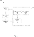
- a nose wheel actuator assembly 100 may comprise a motor portion 110, a damper portion 120, and a housing 130 configured to at least partially surround the motor portion 110 and the damper portion 120 in accordance with various embodiments.
- the nose wheel actuator assembly 100 is disposed about an axial centerline axis, which is the axis of rotation 102.
- the motor portion 110 is configured to generate power to steer a nose wheel of an aircraft.
- the damper portion 120 may comprise a permanent magnet electric machine.
- the damper portion 120 may comprise a stator assembly 122 coaxially aligned with a rotor assembly 124 and disposed about a rotor shaft 126.
- the stator assembly 122 may comprise a conductive material.
- the rotor assembly 124 may comprise one or more permanent magnets 423 (with momentary reference to FIG. 4 ).
- the permanent magnets 423 (with momentary reference to FIG. 4 ) disposed on the rotor assembly 124 rotate relative to the stator assembly 122, creating eddy currents.
- Such eddy currents create electromagnetic drag torque on the motor portion 110.
- FIG. 1 provides a general understanding of various portions of a nose wheel actuator assembly, and is not intended to limit the disclosure.
- a saturation-controlled variable damper 200 may comprise a stator assembly 122 configured to adjustably control drag torque created by the saturation-controlled variable damper 200.
- a damping coefficient of the saturation-controlled variable damper 200 may be variable.
- the saturation-controlled variable damper 200 may create drag torque proportional to the speed of the rotor shaft 126 by a variable damping coefficient.
- the variable damping coefficient may be adjustably controlled by application of a variable current to a control winding 230 of stator assembly 122.
- the saturation-controlled variable damper 200 may comprise a controller 270 configured to adjustably control at least one of a voltage applied to the control winding 230 or a current generated in the control winding 230.
- the controller 270 may be configured to command the application of a voltage to the control winding 230.
- the controller 270 may be configured to command the application of a direct current to the control winding 230.
- the controller 270 may be in electrical communication with at least one of the stator assembly 122 and the rotor shaft 126. In various embodiments, the controller 270 may be in electrical communication with the control winding 230. In various embodiments, the controller 270 may be configured to adjustably control rotation of the rotor shaft 126. In various embodiments, the controller 270 may comprise at least one of a flight control system or a steering control system. In various embodiments, the controller 270 may comprise a processor configured to implement various logical operations in response to execution of instructions, for example, instructions stored on a non-transitory, tangible, computer-readable medium.
- the stator assembly 122 may comprise a high damping core 210 coaxially aligned with, and disposed about, a low damping core 220.
- the high damping core 210 and the low damping core 220 may comprise portions of an integral stator.
- the high damping core 210 and the low damping core 220 may comprise separate stators that are coaxially aligned and/or operatively coupled.
- the high damping core 210 may comprise a plurality of slots 312 defined between a plurality of teeth 314.
- the plurality of slots 312, and the plurality of teeth 314 may be disposed radially about the axis of rotation 102.
- each slot of the plurality of slots 312 may extend from a first axial end face 602 to a second axial end face 603 of the stator assembly 122.
- the high damping core 210 may further comprise a bridge portion 316 extending circumferentially about the axis of rotation 102 and bridging adjacent teeth in the plurality of teeth 314.
- the high damping core 210 may be configured to produce eddy currents in response to relative motion between the stator assembly 122 and the rotor assembly 124.
- the high damping core 210 may comprise a conductive material.
- the high damping core 210 may comprise at least one of a metal, a metal alloy, or a combination of one or more metals or alloys.
- the high damping core 210 may comprise at least one of aluminum, copper, or steel.
- the high damping core 210 may comprise any material suitable for use in the stator assembly 122.
- the low damping core 220 may be configured to decrease or minimize production of eddy currents in response to relative motion between the stator assembly 122 and the rotor assembly 124.
- the low damping core 220 may comprise an electromagnetic material.
- the low damping core 220 may comprise at least one of a metal, a metal alloy, or a combination of one or more metals or alloys.
- the low damping core 220 may comprise steel.
- the low damping core 220 may comprise any material suitable for use in the stator assembly 122.
- the low damping core 220 may comprise a plurality of laminations.
- the low damping core 220 may comprise a plurality of low damping core slots 322 defined between a plurality of low damping core teeth 324.
- the plurality of low damping core slots 322, and the plurality of low damping core teeth 324 may be disposed radially about the axis of rotation 102.
- each slot of the plurality of slots 322 may extend from a first axial end face 602 to a second axial end face 603 of the stator assembly 122.
- the plurality of low damping core slots 322 may be circumferentially aligned with the plurality of slots 312 disposed in the high damping core 210.
- the plurality of low damping core teeth 324 may be circumferentially aligned with the plurality of teeth 314 disposed in the high damping core 210.
- the low damping core 220 may comprise a back iron 326 extending circumferentially about axis of rotation 102 radially inward of the plurality of low damping core teeth 324.
- the back iron 326 may bridge each adjacent pair of low damping core teeth of the plurality of low damping core teeth 324.
- the stator assembly 122 may further comprise a control winding 230 configured to receive a direct current (DC).
- the control winding 230 may be in communication with the controller 270.
- the control winding 230 may be in communication with an external voltage source.
- the control winding 230 may comprise at least one of a wire or a foil.
- the control winding 230 may comprise a copper wire.
- the control winding 230 may comprise any conductor suitable for use in the stator assembly 122.
- the control winding 230 may be wound about the high damping core 210 such that the control winding 230 enters each slot of the plurality of slots from at least one of the first axial end face 602 or the second axial end face 603.
- the control winding 230 may be wound circumferentially about the bridge portion 316 between adjacent teeth of the plurality of teeth 314.
- the control winding 230 may be wound about the high damping core 210 such that the control winding 230 exits each slot of the plurality of slots from at least one of the first axial end face 602 or the second axial end face 603.
- the control winding 230 may be integrally continuous. Stated differently, in various embodiments, the control winding 230 may comprise a single member that is continuous from a first control winding end to a second control winding end.
- the stator assembly 122 may further comprise a secondary winding 332.
- the secondary winding 332 may comprise at least one of a conductor wire or a conductor foil.
- the secondary winding 332 may be wound about the low damping core 220.
- a saturation-controlled variable damper 400 may comprise a stator assembly 422 at least partially surrounded by a rotor assembly 424.
- the rotor assembly 424 may comprise a plurality of permanent magnets 423 retained by a yoke 425 and a retention sleeve portion 426.
- a rotor air gap 440 separates the rotor assembly 424 and the stator assembly 422 in a typical fashion.
- the rotor assembly 424 is operatively coupled to the rotor shaft 126, such that rotation of the rotor shaft 126 causes rotation of the rotor assembly 424 about the axis of rotation 102.
- the rotation of rotor shaft 126 causes rotation of the plurality of permanent magnets 423 about the stator assembly 422.
- rotation of the rotor assembly 424 about the stator assembly 422 may create an eddy current in the stator assembly 422.
- interaction of the plurality of permanent magnets 423 and the control winding 230 creates alternating magnetic flux within the saturation-controlled variable damper 400.
- the alternating magnetic flux is communicated about a high-damping magnetic flux path 510 within the saturation-controlled variable damper 400, as represented schematically in FIG. 5a .
- the high-damping magnetic flux path 510 includes the rotor assembly 424, the rotor air gap 440, the bridge portion 316, the high damping core 210, and a portion of each tooth of the plurality of teeth 314 disposed between the rotor assembly 424 and the bridge portion 316.
- the magnetic flux path 510 encircles at least a portion of the control winding 230 and, in use, creates an eddy current in the high damping core 210 and a first drag torque that opposes the rotation of the rotor assembly 424.
- application of a first current through the control winding 230 may saturate the high damping core 210 with a constant magnetic flux.
- at least a portion of the alternating flux may be diverted from at least a portion of the high damping core 210 to at least a portion of the low damping core 220.
- at least a portion of the alternating flux may be diverted such that it is communicated about a low-damping magnetic flux path 520, as represented schematically in FIG. 5c .
- the low-damping magnetic flux path 520 includes the rotor assembly 424, the rotor air gap 440, the bridge 316, the low damping core 220, and the portion of each tooth of the plurality of teeth 314 disposed between the rotor assembly 424 and the bridge portion 316.
- the low damping core 220 may be configured to decrease or minimize generation of eddy current in the stator assembly 422 in response to communication of the alternating flux through the low-damping magnetic flux path 520. Accordingly, in response to communication of direct current through the control winding 230, interaction of the plurality of permanent magnets 423 and the control winding 230 may create a second drag torque that opposes the rotation of the rotor assembly 424. In such embodiments, the second drag torque may be less than the first drag torque.
- the amplitude of direct current communicated through the control winding 230 may be adjustably controlled.
- saturation of the high damping core 210 with a constant magnetic flux may increase or may decrease.
- interaction of the plurality of permanent magnets 423 and the control winding 230 may create a third drag torque that opposes the rotation of the rotor assembly 424.
- the third drag torque may be greater than, less than, or equal to the second drag torque.
- any of the hereinbefore described embodiments may comprise a saturation-controlled variable damper having a conventional configuration as shown in FIG. 6 .
- a saturation-controlled variable damper 600 may comprise a stator assembly 622 disposed radially outward of a rotor assembly 624, wherein the rotor assembly 624 comprises a plurality of permanent magnets 625 arranged in a generally cylindrical pattern facing radially outward toward the stator assembly 622.
- a low damping core 620 may be disposed radially outward of a high damping core 610.
- a method 700 may allow variable control of a drag torque generated by the saturation-controlled variable damper 200.
- the amplitude of a direct current applied through control winding 230 may be proportional to a level of saturation of the high damping core 210 with a constant magnetic flux.
- the high damping core 210 may be partially saturated with a constant magnetic flux.
- the level of saturation of the high damping core 210 with a constant magnetic flux may be indirectly proportional to the amount of drag torque generated by the saturation-controlled variable damper 200.
- the drag torque generated by the saturation-controlled variable damper 200 may be adjustably controlled by controlling the amplitude of a direct current applied through control winding 230.
- the method 700 may comprise applying at least a first current and a second current through the control winding 230 of the saturation-controlled variable damper 200 (Step 701). In various embodiments, the method 700 may further comprise generating a first drag torque in response to the first current being applied through the control winding 230 (Step 702), and generating a second drag torque in response to the second current being applied through the control winding 230 (Step 703). In various embodiments, the applying may be by the controller 270. In various embodiments, the generating the first drag torque may be by the saturation-controlled variable damper 200. In various embodiments, the generating the second drag torque may be by the saturation-controlled variable damper 200.
- the first current may be zero. In various embodiments, the first drag torque may be greater than zero in response to the first current being zero. In various embodiments, the second current may be greater than zero. In various embodiments, the second drag torque may be less than the first drag torque in response to the second current being greater than the first current. Stated differently, in various embodiments, the drag torque generated by the saturation-controlled variable damper 200 may be inversely proportional to the current applied through the control winding 230. In various embodiments, the current may be continuously variable. In various embodiments, application of a continuously variable current through the control winding 230 may generate a continuously variable drag torque.
- references to “one embodiment”, “an embodiment”, “various embodiments”, etc. indicate that the embodiment described may include a particular feature, structure, or characteristic, but every embodiment may not necessarily include the particular feature, structure, or characteristic. Moreover, such phrases are not necessarily referring to the same embodiment. Further, when a particular feature, structure, or characteristic is described in connection with an embodiment, it is submitted that it is within the knowledge of one skilled in the art to affect such feature, structure, or characteristic in connection with other embodiments whether or not explicitly described. After reading the description, it will be apparent to one skilled in the relevant art(s) how to implement the disclosure in alternative embodiments.
Applications Claiming Priority (1)
| Application Number | Priority Date | Filing Date | Title |
|---|---|---|---|
| US14/882,086 US9765850B2 (en) | 2015-10-13 | 2015-10-13 | Saturation-controlled variable damper systems and methods |
Publications (3)
| Publication Number | Publication Date |
|---|---|
| EP3156325A2 true EP3156325A2 (fr) | 2017-04-19 |
| EP3156325A3 EP3156325A3 (fr) | 2017-05-31 |
| EP3156325B1 EP3156325B1 (fr) | 2018-12-12 |
Family
ID=57189782
Family Applications (1)
| Application Number | Title | Priority Date | Filing Date |
|---|---|---|---|
| EP16193472.4A Active EP3156325B1 (fr) | 2015-10-13 | 2016-10-12 | Systèmes d'amortisseur variable à saturation contrôlée et procédés |
Country Status (2)
| Country | Link |
|---|---|
| US (1) | US9765850B2 (fr) |
| EP (1) | EP3156325B1 (fr) |
Cited By (2)
| Publication number | Priority date | Publication date | Assignee | Title |
|---|---|---|---|---|
| CN110578297A (zh) * | 2019-08-27 | 2019-12-17 | 河海大学 | 一种适用于拉索任意振动方向的电涡流阻尼器 |
| EP3754823A1 (fr) * | 2019-06-19 | 2020-12-23 | BioCoRe S. Coop. | Groupe électrogène compact à haut rendement pour parcs éoliens |
Families Citing this family (3)
| Publication number | Priority date | Publication date | Assignee | Title |
|---|---|---|---|---|
| DE102014104225A1 (de) * | 2014-03-26 | 2015-10-01 | Feaam Gmbh | Elektrische Maschine |
| US11492104B2 (en) | 2020-03-19 | 2022-11-08 | Goodrich Corporation | Magnetic self-centering shimmy damper |
| CN112249893B (zh) * | 2020-12-23 | 2021-03-19 | 河南工学院 | 一种具有减震装置的起重机 |
Family Cites Families (34)
| Publication number | Priority date | Publication date | Assignee | Title |
|---|---|---|---|---|
| US4663581A (en) | 1984-10-31 | 1987-05-05 | Sundstrand Corporation | Voltage regulated permanent magnet generator system |
| GB2192041B (en) | 1986-06-24 | 1990-10-10 | Fokker Bv | Vibration absorber with controllable resonance frequency |
| JPH0274146A (ja) | 1988-09-06 | 1990-03-14 | Toshiba Corp | 回転体の回転力減衰装置 |
| CA1315328C (fr) | 1988-10-31 | 1993-03-30 | Kenji Araki | Ralentisseur de courant de foucault |
| US5238095A (en) * | 1992-06-30 | 1993-08-24 | Pedu Jeffrey C | Hysteresis brakes and clutches |
| US5236069A (en) * | 1992-07-02 | 1993-08-17 | Peng, Huan-Yau | Braking device for indoor exercise bicycles |
| US5714823A (en) | 1994-08-29 | 1998-02-03 | Sundstrand Corporation | Quasi regulated permanent magnet generator |
| US5803404A (en) * | 1996-01-23 | 1998-09-08 | Mpc Products, Inc. | Door actuation system having a variable damping device |
| US5711404A (en) * | 1997-02-05 | 1998-01-27 | Lee; Ying-Che | Magnetic adjustable loading device with eddy current |
| JPH11285233A (ja) * | 1998-03-30 | 1999-10-15 | Isuzu Motors Ltd | 磁石式渦電流減速装置 |
| US6557673B1 (en) * | 2001-12-21 | 2003-05-06 | Visteon Global Technologies, Inc. | Integral park brake/eddy current brake assembly |
| EP1367701B1 (fr) | 2002-05-28 | 2009-11-04 | Isuzu Motors Limited | Ralentisseur à courant de Foucault |
| US6965183B2 (en) * | 2003-05-27 | 2005-11-15 | Pratt & Whitney Canada Corp. | Architecture for electric machine |
| US7583063B2 (en) * | 2003-05-27 | 2009-09-01 | Pratt & Whitney Canada Corp. | Architecture for electric machine |
| US7253548B2 (en) | 2003-06-16 | 2007-08-07 | Pratt & Whitney Canada Corp. | Method and apparatus for controlling an electric machine |
| CN101292411A (zh) | 2005-10-19 | 2008-10-22 | 劳伦斯·P·策普 | 具有去耦以消除磁感应转矩损失的轴向转子的无刷永磁电动机/发电机 |
| US20080088195A1 (en) | 2006-10-16 | 2008-04-17 | Dooley Kevin A | Outside rotor electric machine |
| FR2930655B1 (fr) * | 2008-04-29 | 2013-02-08 | Commissariat Energie Atomique | Interface a retour d'effort a sensation amelioree |
| JP2010035287A (ja) | 2008-07-25 | 2010-02-12 | Hitachi Ltd | 円筒型リニアモータ及びそれを用いた電磁サスペンション及び電動パワーステアリング装置 |
| EP2373901A4 (fr) | 2008-12-02 | 2018-05-23 | Torbjörn Lembke | Actionneur électrodynamique |
| US20100264768A1 (en) | 2009-04-16 | 2010-10-21 | Gm Global Technology Operations, Inc. | Permanent magnet machine with conical stator |
| US7923874B2 (en) * | 2009-06-17 | 2011-04-12 | Hamilton Sundstrand Corporation | Nested torsional damper for an electric machine |
| US20110006545A1 (en) * | 2009-07-08 | 2011-01-13 | Hamilton Sundstrand Corporation | Nested exciter and main generator stages for a wound field generator |
| US20110062805A1 (en) | 2009-09-17 | 2011-03-17 | Caterpillar Inc. | Switched reluctance machine with eddy current loss dampener |
| US20110101817A1 (en) | 2009-11-05 | 2011-05-05 | Gm Global Technology Operations, Inc. | Variable geometry electric machine |
| GB2480229A (en) | 2010-03-10 | 2011-11-16 | Univ Nottingham | Stator for a flux switching inductor machine |
| SG187234A1 (en) | 2010-07-29 | 2013-02-28 | Univ New York State Res Found | Electricity generating shock absorbers |
| GB2484098A (en) | 2010-09-29 | 2012-04-04 | Nissan Motor Mfg Uk Ltd | Dynamo-electric machine with rotor magnet adjustable shunt |
| CN202503378U (zh) | 2012-03-27 | 2012-10-24 | 中国矿业大学 | 一种三相混合励磁的磁通反向电机 |
| GB2500442B (en) | 2012-08-21 | 2014-03-12 | Messier Dowty Ltd | A brake assembly and a method of operating a brake assembly |
| GB2511856B (en) | 2013-03-15 | 2015-07-01 | Goodrich Actuation Systems Ltd | Damping arrangement for aircraft landing gear, for example a nosewheel |
| CN103208893B (zh) | 2013-03-18 | 2015-08-05 | 南京航空航天大学 | 感应励磁式混合励磁无刷同步电机 |
| EP2916032B1 (fr) | 2014-03-05 | 2019-08-14 | Goodrich Actuation Systems SAS | Ensembles d'amortissement débrayable pour des surfaces aérodynamiques mobiles |
| CN104578659B (zh) | 2015-01-14 | 2017-09-15 | 东南大学 | 一种磁通切换型并联混合永磁记忆电机 |
-
2015
- 2015-10-13 US US14/882,086 patent/US9765850B2/en active Active
-
2016
- 2016-10-12 EP EP16193472.4A patent/EP3156325B1/fr active Active
Non-Patent Citations (1)
| Title |
|---|
| None |
Cited By (2)
| Publication number | Priority date | Publication date | Assignee | Title |
|---|---|---|---|---|
| EP3754823A1 (fr) * | 2019-06-19 | 2020-12-23 | BioCoRe S. Coop. | Groupe électrogène compact à haut rendement pour parcs éoliens |
| CN110578297A (zh) * | 2019-08-27 | 2019-12-17 | 河海大学 | 一种适用于拉索任意振动方向的电涡流阻尼器 |
Also Published As
| Publication number | Publication date |
|---|---|
| US9765850B2 (en) | 2017-09-19 |
| EP3156325B1 (fr) | 2018-12-12 |
| EP3156325A3 (fr) | 2017-05-31 |
| US20170102047A1 (en) | 2017-04-13 |
Similar Documents
| Publication | Publication Date | Title |
|---|---|---|
| EP3156325B1 (fr) | Systèmes d'amortisseur variable à saturation contrôlée et procédés | |
| EP3387740B1 (fr) | Un ensemble stator | |
| EP2782226B1 (fr) | Rotor de machine électrique à aimants permanents avec flux magnétique contrôlé | |
| JP6248711B2 (ja) | 回転電機の固定子 | |
| KR950035005A (ko) | 영구 자석 다이너모 전기 기기 | |
| JP2011010375A (ja) | アキシャル型モータ | |
| US11437898B2 (en) | Brushless direct current motor with dual stators | |
| CN105871156B (zh) | 感应同步电动机 | |
| US20140368075A1 (en) | Permanent magnet synchronous machines with magnetic flux regulation | |
| JP5120801B2 (ja) | 回転機及び回転機を製造する方法 | |
| US20180254688A1 (en) | Wound-rotor synchronous machine with permanent magnets | |
| JPS6326623B2 (fr) | ||
| US9732817B2 (en) | Axial engagement-controlled variable damper systems and methods | |
| EP3118976A1 (fr) | Machine électrique comportant un palier électrodynamique radial | |
| EP3156326B1 (fr) | Systèmes et procédés d'amortisseur variable commandé par enclenchement axial | |
| CN111903037A (zh) | 感应电动机的转子及感应电动机 | |
| JP6645351B2 (ja) | 回転電機 | |
| US10263491B2 (en) | Electromechanical actuator damping | |
| Kohara et al. | Permanent magnet assisted current superimposition variable flux machine | |
| US20160315515A1 (en) | Electromechanical actuator damping | |
| EP3079243A1 (fr) | Générateur électrique | |
| Ooshima et al. | Design methodology for miniaturization of motor equipped in a fluid intermittent control system | |
| WO2020031610A1 (fr) | Stator, machine dynamo-électrique, système auxiliaire électrique pour automobile | |
| EP3490113A1 (fr) | Moteur électrique amorti | |
| KR101955031B1 (ko) | 2개의 회전자가 수 분할된 자석을 이용하는 발전기 |
Legal Events
| Date | Code | Title | Description |
|---|---|---|---|
| PUAI | Public reference made under article 153(3) epc to a published international application that has entered the european phase |
Free format text: ORIGINAL CODE: 0009012 |
|
| STAA | Information on the status of an ep patent application or granted ep patent |
Free format text: STATUS: THE APPLICATION HAS BEEN PUBLISHED |
|
| AK | Designated contracting states |
Kind code of ref document: A2 Designated state(s): AL AT BE BG CH CY CZ DE DK EE ES FI FR GB GR HR HU IE IS IT LI LT LU LV MC MK MT NL NO PL PT RO RS SE SI SK SM TR |
|
| AX | Request for extension of the european patent |
Extension state: BA ME |
|
| PUAL | Search report despatched |
Free format text: ORIGINAL CODE: 0009013 |
|
| AK | Designated contracting states |
Kind code of ref document: A3 Designated state(s): AL AT BE BG CH CY CZ DE DK EE ES FI FR GB GR HR HU IE IS IT LI LT LU LV MC MK MT NL NO PL PT RO RS SE SI SK SM TR |
|
| AX | Request for extension of the european patent |
Extension state: BA ME |
|
| RIC1 | Information provided on ipc code assigned before grant |
Ipc: B64C 25/34 20060101AFI20170421BHEP Ipc: F16F 15/18 20060101ALI20170421BHEP Ipc: B64C 25/50 20060101ALI20170421BHEP Ipc: F16F 15/03 20060101ALI20170421BHEP |
|
| STAA | Information on the status of an ep patent application or granted ep patent |
Free format text: STATUS: REQUEST FOR EXAMINATION WAS MADE |
|
| 17P | Request for examination filed |
Effective date: 20171130 |
|
| RBV | Designated contracting states (corrected) |
Designated state(s): AL AT BE BG CH CY CZ DE DK EE ES FI FR GB GR HR HU IE IS IT LI LT LU LV MC MK MT NL NO PL PT RO RS SE SI SK SM TR |
|
| GRAP | Despatch of communication of intention to grant a patent |
Free format text: ORIGINAL CODE: EPIDOSNIGR1 |
|
| STAA | Information on the status of an ep patent application or granted ep patent |
Free format text: STATUS: GRANT OF PATENT IS INTENDED |
|
| RIC1 | Information provided on ipc code assigned before grant |
Ipc: H02K 16/04 20060101ALI20180418BHEP Ipc: B64C 25/50 20060101ALI20180418BHEP Ipc: F16F 15/03 20060101ALI20180418BHEP Ipc: F16F 7/00 20060101ALI20180418BHEP Ipc: F16F 15/18 20060101ALI20180418BHEP Ipc: B64C 25/34 20060101AFI20180418BHEP Ipc: H02K 1/27 20060101ALI20180418BHEP |
|
| INTG | Intention to grant announced |
Effective date: 20180509 |
|
| GRAS | Grant fee paid |
Free format text: ORIGINAL CODE: EPIDOSNIGR3 |
|
| GRAA | (expected) grant |
Free format text: ORIGINAL CODE: 0009210 |
|
| STAA | Information on the status of an ep patent application or granted ep patent |
Free format text: STATUS: THE PATENT HAS BEEN GRANTED |
|
| AK | Designated contracting states |
Kind code of ref document: B1 Designated state(s): AL AT BE BG CH CY CZ DE DK EE ES FI FR GB GR HR HU IE IS IT LI LT LU LV MC MK MT NL NO PL PT RO RS SE SI SK SM TR |
|
| REG | Reference to a national code |
Ref country code: GB Ref legal event code: FG4D |
|
| REG | Reference to a national code |
Ref country code: CH Ref legal event code: EP |
|
| REG | Reference to a national code |
Ref country code: AT Ref legal event code: REF Ref document number: 1075633 Country of ref document: AT Kind code of ref document: T Effective date: 20181215 |
|
| REG | Reference to a national code |
Ref country code: DE Ref legal event code: R096 Ref document number: 602016008090 Country of ref document: DE |
|
| REG | Reference to a national code |
Ref country code: IE Ref legal event code: FG4D |
|
| REG | Reference to a national code |
Ref country code: NL Ref legal event code: MP Effective date: 20181212 |
|
| REG | Reference to a national code |
Ref country code: LT Ref legal event code: MG4D |
|
| PG25 | Lapsed in a contracting state [announced via postgrant information from national office to epo] |
Ref country code: LV Free format text: LAPSE BECAUSE OF FAILURE TO SUBMIT A TRANSLATION OF THE DESCRIPTION OR TO PAY THE FEE WITHIN THE PRESCRIBED TIME-LIMIT Effective date: 20181212 Ref country code: ES Free format text: LAPSE BECAUSE OF FAILURE TO SUBMIT A TRANSLATION OF THE DESCRIPTION OR TO PAY THE FEE WITHIN THE PRESCRIBED TIME-LIMIT Effective date: 20181212 Ref country code: LT Free format text: LAPSE BECAUSE OF FAILURE TO SUBMIT A TRANSLATION OF THE DESCRIPTION OR TO PAY THE FEE WITHIN THE PRESCRIBED TIME-LIMIT Effective date: 20181212 Ref country code: NO Free format text: LAPSE BECAUSE OF FAILURE TO SUBMIT A TRANSLATION OF THE DESCRIPTION OR TO PAY THE FEE WITHIN THE PRESCRIBED TIME-LIMIT Effective date: 20190312 Ref country code: FI Free format text: LAPSE BECAUSE OF FAILURE TO SUBMIT A TRANSLATION OF THE DESCRIPTION OR TO PAY THE FEE WITHIN THE PRESCRIBED TIME-LIMIT Effective date: 20181212 Ref country code: BG Free format text: LAPSE BECAUSE OF FAILURE TO SUBMIT A TRANSLATION OF THE DESCRIPTION OR TO PAY THE FEE WITHIN THE PRESCRIBED TIME-LIMIT Effective date: 20190312 Ref country code: HR Free format text: LAPSE BECAUSE OF FAILURE TO SUBMIT A TRANSLATION OF THE DESCRIPTION OR TO PAY THE FEE WITHIN THE PRESCRIBED TIME-LIMIT Effective date: 20181212 |
|
| REG | Reference to a national code |
Ref country code: AT Ref legal event code: MK05 Ref document number: 1075633 Country of ref document: AT Kind code of ref document: T Effective date: 20181212 |
|
| PG25 | Lapsed in a contracting state [announced via postgrant information from national office to epo] |
Ref country code: RS Free format text: LAPSE BECAUSE OF FAILURE TO SUBMIT A TRANSLATION OF THE DESCRIPTION OR TO PAY THE FEE WITHIN THE PRESCRIBED TIME-LIMIT Effective date: 20181212 Ref country code: SE Free format text: LAPSE BECAUSE OF FAILURE TO SUBMIT A TRANSLATION OF THE DESCRIPTION OR TO PAY THE FEE WITHIN THE PRESCRIBED TIME-LIMIT Effective date: 20181212 Ref country code: AL Free format text: LAPSE BECAUSE OF FAILURE TO SUBMIT A TRANSLATION OF THE DESCRIPTION OR TO PAY THE FEE WITHIN THE PRESCRIBED TIME-LIMIT Effective date: 20181212 Ref country code: GR Free format text: LAPSE BECAUSE OF FAILURE TO SUBMIT A TRANSLATION OF THE DESCRIPTION OR TO PAY THE FEE WITHIN THE PRESCRIBED TIME-LIMIT Effective date: 20190313 |
|
| PG25 | Lapsed in a contracting state [announced via postgrant information from national office to epo] |
Ref country code: NL Free format text: LAPSE BECAUSE OF FAILURE TO SUBMIT A TRANSLATION OF THE DESCRIPTION OR TO PAY THE FEE WITHIN THE PRESCRIBED TIME-LIMIT Effective date: 20181212 |
|
| PG25 | Lapsed in a contracting state [announced via postgrant information from national office to epo] |
Ref country code: PL Free format text: LAPSE BECAUSE OF FAILURE TO SUBMIT A TRANSLATION OF THE DESCRIPTION OR TO PAY THE FEE WITHIN THE PRESCRIBED TIME-LIMIT Effective date: 20181212 Ref country code: IT Free format text: LAPSE BECAUSE OF FAILURE TO SUBMIT A TRANSLATION OF THE DESCRIPTION OR TO PAY THE FEE WITHIN THE PRESCRIBED TIME-LIMIT Effective date: 20181212 Ref country code: CZ Free format text: LAPSE BECAUSE OF FAILURE TO SUBMIT A TRANSLATION OF THE DESCRIPTION OR TO PAY THE FEE WITHIN THE PRESCRIBED TIME-LIMIT Effective date: 20181212 Ref country code: PT Free format text: LAPSE BECAUSE OF FAILURE TO SUBMIT A TRANSLATION OF THE DESCRIPTION OR TO PAY THE FEE WITHIN THE PRESCRIBED TIME-LIMIT Effective date: 20190412 |
|
| PG25 | Lapsed in a contracting state [announced via postgrant information from national office to epo] |
Ref country code: IS Free format text: LAPSE BECAUSE OF FAILURE TO SUBMIT A TRANSLATION OF THE DESCRIPTION OR TO PAY THE FEE WITHIN THE PRESCRIBED TIME-LIMIT Effective date: 20190412 Ref country code: RO Free format text: LAPSE BECAUSE OF FAILURE TO SUBMIT A TRANSLATION OF THE DESCRIPTION OR TO PAY THE FEE WITHIN THE PRESCRIBED TIME-LIMIT Effective date: 20181212 Ref country code: EE Free format text: LAPSE BECAUSE OF FAILURE TO SUBMIT A TRANSLATION OF THE DESCRIPTION OR TO PAY THE FEE WITHIN THE PRESCRIBED TIME-LIMIT Effective date: 20181212 Ref country code: SM Free format text: LAPSE BECAUSE OF FAILURE TO SUBMIT A TRANSLATION OF THE DESCRIPTION OR TO PAY THE FEE WITHIN THE PRESCRIBED TIME-LIMIT Effective date: 20181212 Ref country code: SK Free format text: LAPSE BECAUSE OF FAILURE TO SUBMIT A TRANSLATION OF THE DESCRIPTION OR TO PAY THE FEE WITHIN THE PRESCRIBED TIME-LIMIT Effective date: 20181212 |
|
| REG | Reference to a national code |
Ref country code: DE Ref legal event code: R097 Ref document number: 602016008090 Country of ref document: DE |
|
| PLBE | No opposition filed within time limit |
Free format text: ORIGINAL CODE: 0009261 |
|
| STAA | Information on the status of an ep patent application or granted ep patent |
Free format text: STATUS: NO OPPOSITION FILED WITHIN TIME LIMIT |
|
| PG25 | Lapsed in a contracting state [announced via postgrant information from national office to epo] |
Ref country code: AT Free format text: LAPSE BECAUSE OF FAILURE TO SUBMIT A TRANSLATION OF THE DESCRIPTION OR TO PAY THE FEE WITHIN THE PRESCRIBED TIME-LIMIT Effective date: 20181212 Ref country code: DK Free format text: LAPSE BECAUSE OF FAILURE TO SUBMIT A TRANSLATION OF THE DESCRIPTION OR TO PAY THE FEE WITHIN THE PRESCRIBED TIME-LIMIT Effective date: 20181212 Ref country code: SI Free format text: LAPSE BECAUSE OF FAILURE TO SUBMIT A TRANSLATION OF THE DESCRIPTION OR TO PAY THE FEE WITHIN THE PRESCRIBED TIME-LIMIT Effective date: 20181212 |
|
| 26N | No opposition filed |
Effective date: 20190913 |
|
| PG25 | Lapsed in a contracting state [announced via postgrant information from national office to epo] |
Ref country code: TR Free format text: LAPSE BECAUSE OF FAILURE TO SUBMIT A TRANSLATION OF THE DESCRIPTION OR TO PAY THE FEE WITHIN THE PRESCRIBED TIME-LIMIT Effective date: 20181212 |
|
| PG25 | Lapsed in a contracting state [announced via postgrant information from national office to epo] |
Ref country code: MC Free format text: LAPSE BECAUSE OF FAILURE TO SUBMIT A TRANSLATION OF THE DESCRIPTION OR TO PAY THE FEE WITHIN THE PRESCRIBED TIME-LIMIT Effective date: 20181212 |
|
| REG | Reference to a national code |
Ref country code: CH Ref legal event code: PL |
|
| PG25 | Lapsed in a contracting state [announced via postgrant information from national office to epo] |
Ref country code: LI Free format text: LAPSE BECAUSE OF NON-PAYMENT OF DUE FEES Effective date: 20191031 Ref country code: CH Free format text: LAPSE BECAUSE OF NON-PAYMENT OF DUE FEES Effective date: 20191031 Ref country code: LU Free format text: LAPSE BECAUSE OF NON-PAYMENT OF DUE FEES Effective date: 20191012 |
|
| REG | Reference to a national code |
Ref country code: BE Ref legal event code: MM Effective date: 20191031 |
|
| PG25 | Lapsed in a contracting state [announced via postgrant information from national office to epo] |
Ref country code: BE Free format text: LAPSE BECAUSE OF NON-PAYMENT OF DUE FEES Effective date: 20191031 |
|
| PG25 | Lapsed in a contracting state [announced via postgrant information from national office to epo] |
Ref country code: IE Free format text: LAPSE BECAUSE OF NON-PAYMENT OF DUE FEES Effective date: 20191012 |
|
| PG25 | Lapsed in a contracting state [announced via postgrant information from national office to epo] |
Ref country code: CY Free format text: LAPSE BECAUSE OF FAILURE TO SUBMIT A TRANSLATION OF THE DESCRIPTION OR TO PAY THE FEE WITHIN THE PRESCRIBED TIME-LIMIT Effective date: 20181212 |
|
| GBPC | Gb: european patent ceased through non-payment of renewal fee |
Effective date: 20201012 |
|
| PG25 | Lapsed in a contracting state [announced via postgrant information from national office to epo] |
Ref country code: HU Free format text: LAPSE BECAUSE OF FAILURE TO SUBMIT A TRANSLATION OF THE DESCRIPTION OR TO PAY THE FEE WITHIN THE PRESCRIBED TIME-LIMIT; INVALID AB INITIO Effective date: 20161012 Ref country code: MT Free format text: LAPSE BECAUSE OF FAILURE TO SUBMIT A TRANSLATION OF THE DESCRIPTION OR TO PAY THE FEE WITHIN THE PRESCRIBED TIME-LIMIT Effective date: 20181212 |
|
| PG25 | Lapsed in a contracting state [announced via postgrant information from national office to epo] |
Ref country code: GB Free format text: LAPSE BECAUSE OF NON-PAYMENT OF DUE FEES Effective date: 20201012 |
|
| PG25 | Lapsed in a contracting state [announced via postgrant information from national office to epo] |
Ref country code: MK Free format text: LAPSE BECAUSE OF FAILURE TO SUBMIT A TRANSLATION OF THE DESCRIPTION OR TO PAY THE FEE WITHIN THE PRESCRIBED TIME-LIMIT Effective date: 20181212 |
|
| REG | Reference to a national code |
Ref country code: FR Ref legal event code: PLFP Year of fee payment: 7 |
|
| P01 | Opt-out of the competence of the unified patent court (upc) registered |
Effective date: 20230522 |
|
| PGFP | Annual fee paid to national office [announced via postgrant information from national office to epo] |
Ref country code: FR Payment date: 20230920 Year of fee payment: 8 |
|
| PGFP | Annual fee paid to national office [announced via postgrant information from national office to epo] |
Ref country code: DE Payment date: 20230920 Year of fee payment: 8 |