EP3156317A2 - Laying vessel, auxiliary structure, system and method for handling reels and reel - Google Patents
Laying vessel, auxiliary structure, system and method for handling reels and reel Download PDFInfo
- Publication number
- EP3156317A2 EP3156317A2 EP16187172.8A EP16187172A EP3156317A2 EP 3156317 A2 EP3156317 A2 EP 3156317A2 EP 16187172 A EP16187172 A EP 16187172A EP 3156317 A2 EP3156317 A2 EP 3156317A2
- Authority
- EP
- European Patent Office
- Prior art keywords
- reel
- auxiliary structure
- reels
- bridge
- laying vessel
- Prior art date
- Legal status (The legal status is an assumption and is not a legal conclusion. Google has not performed a legal analysis and makes no representation as to the accuracy of the status listed.)
- Granted
Links
Images




Classifications
-
- F—MECHANICAL ENGINEERING; LIGHTING; HEATING; WEAPONS; BLASTING
- F16—ENGINEERING ELEMENTS AND UNITS; GENERAL MEASURES FOR PRODUCING AND MAINTAINING EFFECTIVE FUNCTIONING OF MACHINES OR INSTALLATIONS; THERMAL INSULATION IN GENERAL
- F16L—PIPES; JOINTS OR FITTINGS FOR PIPES; SUPPORTS FOR PIPES, CABLES OR PROTECTIVE TUBING; MEANS FOR THERMAL INSULATION IN GENERAL
- F16L1/00—Laying or reclaiming pipes; Repairing or joining pipes on or under water
- F16L1/12—Laying or reclaiming pipes on or under water
- F16L1/20—Accessories therefor, e.g. floats or weights
- F16L1/202—Accessories therefor, e.g. floats or weights fixed on or to vessels
- F16L1/207—Pipe handling apparatus
-
- B—PERFORMING OPERATIONS; TRANSPORTING
- B63—SHIPS OR OTHER WATERBORNE VESSELS; RELATED EQUIPMENT
- B63B—SHIPS OR OTHER WATERBORNE VESSELS; EQUIPMENT FOR SHIPPING
- B63B27/00—Arrangement of ship-based loading or unloading equipment for cargo or passengers
- B63B27/14—Arrangement of ship-based loading or unloading equipment for cargo or passengers of ramps, gangways or outboard ladders ; Pilot lifts
- B63B27/143—Ramps
-
- B—PERFORMING OPERATIONS; TRANSPORTING
- B63—SHIPS OR OTHER WATERBORNE VESSELS; RELATED EQUIPMENT
- B63B—SHIPS OR OTHER WATERBORNE VESSELS; EQUIPMENT FOR SHIPPING
- B63B27/00—Arrangement of ship-based loading or unloading equipment for cargo or passengers
- B63B27/30—Arrangement of ship-based loading or unloading equipment for transfer at sea between ships or between ships and off-shore structures
-
- B—PERFORMING OPERATIONS; TRANSPORTING
- B63—SHIPS OR OTHER WATERBORNE VESSELS; RELATED EQUIPMENT
- B63B—SHIPS OR OTHER WATERBORNE VESSELS; EQUIPMENT FOR SHIPPING
- B63B35/00—Vessels or similar floating structures specially adapted for specific purposes and not otherwise provided for
- B63B35/03—Pipe-laying vessels
-
- B—PERFORMING OPERATIONS; TRANSPORTING
- B63—SHIPS OR OTHER WATERBORNE VESSELS; RELATED EQUIPMENT
- B63B—SHIPS OR OTHER WATERBORNE VESSELS; EQUIPMENT FOR SHIPPING
- B63B35/00—Vessels or similar floating structures specially adapted for specific purposes and not otherwise provided for
- B63B35/04—Cable-laying vessels
-
- F—MECHANICAL ENGINEERING; LIGHTING; HEATING; WEAPONS; BLASTING
- F16—ENGINEERING ELEMENTS AND UNITS; GENERAL MEASURES FOR PRODUCING AND MAINTAINING EFFECTIVE FUNCTIONING OF MACHINES OR INSTALLATIONS; THERMAL INSULATION IN GENERAL
- F16L—PIPES; JOINTS OR FITTINGS FOR PIPES; SUPPORTS FOR PIPES, CABLES OR PROTECTIVE TUBING; MEANS FOR THERMAL INSULATION IN GENERAL
- F16L1/00—Laying or reclaiming pipes; Repairing or joining pipes on or under water
- F16L1/12—Laying or reclaiming pipes on or under water
-
- F—MECHANICAL ENGINEERING; LIGHTING; HEATING; WEAPONS; BLASTING
- F16—ENGINEERING ELEMENTS AND UNITS; GENERAL MEASURES FOR PRODUCING AND MAINTAINING EFFECTIVE FUNCTIONING OF MACHINES OR INSTALLATIONS; THERMAL INSULATION IN GENERAL
- F16L—PIPES; JOINTS OR FITTINGS FOR PIPES; SUPPORTS FOR PIPES, CABLES OR PROTECTIVE TUBING; MEANS FOR THERMAL INSULATION IN GENERAL
- F16L1/00—Laying or reclaiming pipes; Repairing or joining pipes on or under water
- F16L1/12—Laying or reclaiming pipes on or under water
- F16L1/20—Accessories therefor, e.g. floats or weights
- F16L1/202—Accessories therefor, e.g. floats or weights fixed on or to vessels
- F16L1/203—Accessories therefor, e.g. floats or weights fixed on or to vessels the pipes being wound spirally prior to laying
-
- F—MECHANICAL ENGINEERING; LIGHTING; HEATING; WEAPONS; BLASTING
- F16—ENGINEERING ELEMENTS AND UNITS; GENERAL MEASURES FOR PRODUCING AND MAINTAINING EFFECTIVE FUNCTIONING OF MACHINES OR INSTALLATIONS; THERMAL INSULATION IN GENERAL
- F16L—PIPES; JOINTS OR FITTINGS FOR PIPES; SUPPORTS FOR PIPES, CABLES OR PROTECTIVE TUBING; MEANS FOR THERMAL INSULATION IN GENERAL
- F16L1/00—Laying or reclaiming pipes; Repairing or joining pipes on or under water
- F16L1/12—Laying or reclaiming pipes on or under water
- F16L1/20—Accessories therefor, e.g. floats or weights
- F16L1/202—Accessories therefor, e.g. floats or weights fixed on or to vessels
- F16L1/205—Pipe-laying ships
-
- H—ELECTRICITY
- H02—GENERATION; CONVERSION OR DISTRIBUTION OF ELECTRIC POWER
- H02G—INSTALLATION OF ELECTRIC CABLES OR LINES, OR OF COMBINED OPTICAL AND ELECTRIC CABLES OR LINES
- H02G1/00—Methods or apparatus specially adapted for installing, maintaining, repairing or dismantling electric cables or lines
- H02G1/06—Methods or apparatus specially adapted for installing, maintaining, repairing or dismantling electric cables or lines for laying cables, e.g. laying apparatus on vehicle
- H02G1/10—Methods or apparatus specially adapted for installing, maintaining, repairing or dismantling electric cables or lines for laying cables, e.g. laying apparatus on vehicle in or under water
Definitions
- the present invention relates to a laying vessel for handling reels for laying elongated members on the bed of a body of water.
- the present invention relates also to an auxiliary structure, a reel and a system and a method for handling reels.
- the present invention relates in general to the laying of elongated members on the bed of a body of water by means of a laying vessel.
- the elongated members in this case underwater pipelines or cables, are composed of strings, each of which is wound on a reel, and is unwound gradually off the reel, from an unreeling station on board a laying vessel, and laid on the bed of the body of water as the laying vessel moves forward.
- One of the most critical aspects of this laying technique is feeding the strings to the laying vessel once the reel is unwound.
- the laying vessel When the reel is mounted in a fixed position on the laying vessel and the string is reeled off completely, the laying vessel returns to the quay to wind the reel with another string of the elongated member.
- the string is prefabricated at the quay and simultaneously wound onto the reel on the laying vessel. This operating method involves considerable, and costly, downtime of the laying vessel, which remains substantially idle the whole time the string is being prefabricated.
- Patent US 7,544,013 proposes prefabricating the strings on a floating auxiliary structure; winding the string onto a reel on the floating auxiliary structure; and transferring the string to a reel on the laying vessel, by unreeling the string off the reel on the floating auxiliary structure, and simultaneously reeling it onto the reel on the laying vessel. This method reduces the downtime involved in prefabricating the string, but not the time taken to transfer to string from one reel to another.
- An alternative transfer method employs releasable reels that can be detached from the laying vessel, winds the reels in an auxiliary structure, and transfers the reels from the auxiliary structure to the laying vessel.
- a laying vessel for laying continuous elongated members unwound off reels, the laying vessel comprising a main deck; at least one unreeling station along the main deck comprising an unreeling device for supporting the reel for rotation;; a pit formed in the main deck, beneath the unreeling station; and an elevator housed in the pit to lift and lower the reels.
- This configuration allows raising and lowering the reel from below at the unreeling station without making use of cranes.
- the laying vessel comprises a support assembly for supporting a bridge for transferring reels.
- the support assembly comprises at least one heave compensating device.
- the heave compensation device improves stability of the bridge even in case of rough sea.
- the support assembly comprises two supports each comprising a supporting point for the bridge; the supporting point being located along the longitudinal plane of symmetry of the laying vessel.
- This configuration further reduces the oscillation of the bridge.
- the laying vessel comprises an elevator for lifting/releasing the reel off/onto the bridge and positioning the reel at the unreeling device.
- the elevator can transfer the reels from the bridge to the unreeling device and viceversa.
- Another object of the present invention is to provide an auxiliary structure designed to eliminate or at least reduce the drawbacks of the known art.
- an auxiliary structure for handling reels for laying elongated members on the bed of a body of water, and in particular for transferring reels between the auxiliary structure and a laying vessel;
- the auxiliary structure comprising at least one bridge designed to connect the auxiliary structure and the laying vessel, and to guide the reels along a path extending over the auxiliary structure and the laying vessel; and the auxiliary structure being in particular a floating auxiliary structure, in particular a barge.
- the bridge comprises two guides so as to offer two resting lines for the reel.
- the guides are movable between a work position, in which they are parallel to each other, with a given gauge, to define the bridge, and a rest position.
- the bridge is conveniently movable between a working position and a rest position.
- the guides are mounted on the auxiliary structure in sliding manner.
- This configuration allows changing the gauge of the guides between a position in which the guides define a support for the reel, and a position in which the guides do not interfere with the reel.
- the bridge comprises runners designed to run along the guides and support the reel for enhancing the advancement of the reels along the bridge and reducing friction.
- each runner has an actuator for lifting the top of the runner and the reel to enhance the transfer of the reels to and off the bridge.
- the auxiliary structure has at least one reeling station for winding a string onto a reel.
- the auxiliary structure comprises at least one assembly line for assembling strings; said reeling station being aligned with the assembly line.
- auxiliary structure has a transfer station for loading/unloading the reels onto/off the bridge; and a trolley movable between the reeling station and the transfer station; in particular, the trolley being designed for location underneath the bridge, and to allow the reel on the trolley to be loaded onto the bridge at the transfer station.
- a further object of the present invention is to provide a method for handling reels in order to eliminate or at least reduce the drawbacks of the known art.
- a method for handling reels for laying elongated members on the bed of a body of water comprising the step of:
- a system for handling reels for laying elongated members on the bed of a body of water comprising:
- a further object of the present invention is to provide a reel for unwinding continuous elongated members and designed to eliminate or at least reduce the drawbacks of the known art.
- a reel for unwinding continuous elongated members on a bed of a body of water, wherein the reel has an axis of rotation, and comprises two grip points along the axis of rotation; and two facing retaining shoulders, which are configured to support the entire reel.
- the two grip points and the two facing retaining shoulders offer different support for the reel that allows transferring easily the reel.
- each retaining shoulder has two first supporting points, in particular recesses.
- each retaining shoulder has two second supporting points, in particular recesses.
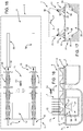
- Figure 1 shows as a whole a system for handling reels 1, and in particular for transferring reels 1 between an auxiliary structure 2 and a laying vessel 3. More specifically, the system according to the invention is designed to transfer reels 1, wound with strings 4 for forming an underwater pipeline (not shown in the drawings), from auxiliary structure 2 to laying vessel 3, and to transfer unwound reels 1 from laying vessel 3 to auxiliary structure 2.
- Reference number 1 indicates both wound and fully or partly unwound reels.
- auxiliary structure 2 is a floating auxiliary structure, preferably a barge equipped with bumpers and drawn up alongside a quay 5 on one side, and alongside laying vessel 3 on the other.
- Auxiliary structure 2 has a platform 6 supporting a reeling station 7 for winding strings 4 onto reels 1; an assembly line 8 for assembling strings 4 or portions of strings 4; and a transfer station 9 for loading and unloading reels 1.
- Auxiliary structure 2 also comprises paths extending along platform 6 to connect reeling station 7, transfer station 9 and storage areas.
- Laying vessel 3 has a main deck 10; an unreeling station 11 where strings 4 are unwound off reels 1; and a pit 12 located at unreeling station 11.
- Pit 12 is in the form of a recess, i.e. a hold, formed in main deck 10.
- the system comprises a bridge 13 designed to connect auxiliary structure 2 and laying vessel 3; and actuators 14 for moving reel 1 along bridge 13.
- Bridge 13 and reels 1 are designed so that one reel 1 at a time can be supported stably on bridge 13.
- bridge 13 extends partly over platform 6 and partly over main deck 10 of laying vessel 3.
- bridge 13 extends from transfer station 9 to unreeling station 11, which in fact are also the stations where reels 1 are loaded/unloaded onto/off bridge 13.
- Each reel 1 has an axis of rotation A, and is designed to be moved along bridge 13 in a direction D1 parallel to axis of rotation A.
- the reel and bridge are designed to position the reel on the bridge with its axis of rotation crosswise to the guides, and to move the reel along the guides in a direction parallel to the guides and perpendicular to the axis of rotation of the reel.
- each reel 1 is transferred without having to be suspended from a crane. In point of fact, reel 1 is supported at all times.
- Reel 1 is an integral part of the handling system, and is in fact designed to cooperate with various component parts of the system to rest on various types of supports with which the system is equipped.
- each reel 1 comprises a drum 15; and two facing retaining shoulders 16 on opposite sides of drum 15.
- Each reel 1 is substantially defined by a cylindrical body extending about axis of rotation A.
- Strings 4 ( Figure 1 ) are wound onto drum 15, and are retained by retaining shoulders 16.
- retaining shoulders 16 also serve to support the entire reel 1 and relative string ( Figure 1 ) when the reel is positioned resting on a support by the retaining shoulders. Consequently, retaining shoulders 16 are designed for this function.
- each reel 1 comprises two grip points 17 aligned along axis of rotation A.
- Each grip point 17 comprises an axial hole engaged by a gripper 18 comprising a shaft.
- reel 1 can be rotated about axis of rotation A by the shafts, or by at least one of the shafts, of grippers 18.
- each reel 1 has four supporting points 19, only two of which are shown in Figure 2 .
- the outer edge of each retaining shoulder 16 has two supporting points 19.
- Each supporting point 19 is substantially defined by a recess formed along the outer edge of retaining shoulder 16.
- the four supporting points 19 have respective coplanar supporting faces 20; and respective retaining faces 21 coplanar in pairs.
- Each reel 1 has four supporting points 22, only two of which are shown in Figure 2 .
- the outer edge of each retaining shoulder 16 has two supporting points 22 located between the two supporting points 19.
- Each supporting point 22 is substantially defined by a recess formed in the outer edge of retaining shoulder 16.
- the four supporting points 22 have respective coplanar supporting faces 23; and respective retaining faces 24 coplanar in pairs.
- reel 1 is supported at grip points 17.
- each reel 1 is positioned resting on supporting points 19.
- Each reel 1 is positioned resting on supporting points 22 as it is transferred from reeling station 7 to transfer station 9, and as it is transferred to unreeling station 11 on board laying vessel 3.
- Figure 4 shows bridge 13 in the work position, and an empty reel 1 resting on bridge 13 at transfer station 9.
- bridge 13 comprises two guides 25 which, in the work position, are parallel to each other, with a given gauge, and substantially horizontal.
- Each guide 25 is hinged to platform 6 about an axis A1 perpendicular to guide 25, and can be rotated selectively about axis A1.
- each guide 25 is movable independently of the other.
- Laying vessel 3 comprises a support assembly 26 for supporting bridge 13. More specifically, support assembly 26 is movable with respect to main deck 10 to compensate for wave motion and reduce any oscillation of bridge 13 induced by laying vessel 3.
- support assembly 26 comprises four controlled-yield compensating devices 27 located partly inside pit 12 and comprising plates 28 projecting above main deck 10. Each guide 25 rests on two plates 28.
- Unreeling station 11 has an unreeling device 29 designed to grip reel 1 at grip points 17.
- An elevator 30 is housed inside pit 12, substantially at unreeling station 11, to unload reel 1 off bridge 13, load real 1 onto bridge 13, and position reel 1 at unreeling device 29.
- unreeling device 29 comprises two slides 31 mounted to slide with respect to main deck 10 in a direction D1; and two grippers 18 mounted on slides 31.
- 'direction' is used in the sense of 'path', regardless of the actual direction.
- a direction indicated in the drawings is intended purely by way of example, and does not exclude the possibility of movement in the opposite direction to the one shown in the drawings.
- Unreeling device 29 comprises actuators, not shown in the attached drawings, for moving slides 31 and respective grippers 18 towards and away from each other in two-way direction D1; and to rotate at least one of grippers 18.
- bridge 13 extends over pit 12, in which elevator 30 is housed, and over unreeling device 29.
- elevator 30 comprises two uprights 32 fitted in sliding manner to the lateral walls of pit 12; and a frame 33 connected to uprights 32 and designed to engage a reel 1 resting on bridge 13 at unreeling station 11.
- frame 33 engages reel 1 at supporting points 22, and raises reel 1 with respect to bridge 13.
- bridge 13 is withdrawn, and elevator 30 is lowered inside pit 12 to align the axis of rotation A of reel 1 with grippers 18, which are activated to engage grip points 17 of reel 1, as shown in Figure 6 .
- elevator 30 is lowered further to release frame 33 from supporting points 22 of reel 1 and permit rotation of reel 1.
- reels 1 are transported along platform 6 of auxiliary structure 2 using trolleys 34.
- Each trolley 34 is designed to transport one reel 1 and to travel along paths laid out on platform 6.
- the paths are defined by a grid of rails 35 ( Figure 1 ).
- each trolley 34 is designed to engage and travel along two rails 35.
- Each trolley 34 comprises a frame 36 designed to support reel 1 at supporting points 22.
- Trolley 34 comprises runners 37 fitted to rails 35, and cooperates with actuators 38 ( Figure 11 ) designed to move along rails 35 and to engage and draw along trolley 34.
- Actuators 38 preferably comprise hydraulic jacks.
- Trolley 34 is sized to fit between guides 25 and to transfer reel 1 from trolley 34 to bridge 13 and vice versa.
- Trolley 34 is capable of slight lifting movements by means of actuators 39.
- Bridge 13 also comprises runners 40 fitted to and which run along guides 25.
- Runners 40 are preferably known types, and preferably of the type known as a Hilman rolling platform.
- each runner 40 comprises an actuator 41 designed to raise the top of runner 40 with respect to guide 25.
- reel 1 resting on bridge 13 is positioned resting on four runners 40 designed to run along guides 25.
- trolley 34 positions supporting points 19 on runners 40. By slightly raising runners 40, reel 1 can be lifted off trolley 34 and transferred from trolley 34 to bridge 13. At this point, trolley 34 can be withdrawn from transfer station 9, and reel 1 lowered.
- actuators 14 are designed to draw or push runners 40 and therefore reel 1 along bridge 13.
- Actuators 14 also preferably comprise hydraulic jacks engaging guides 25, and may also serve as a parking brake to hold runners 40 and reel 1 in a given position.
- FIG 8 shows bridge 13 in a rest configuration, in which guides 25 are perpendicular to platform 6. More specifically, bridge 13 comprises actuators, not shown, for rotating guides 25 about axes A1 from the Figure 4 work configuration to the rest configuration, and vice versa. Moving from the work to the rest configuration by simply rotating guides 25 about axes A1, however, is only possible when unreeling station 11 is free of reel 1. In fact, each reel 1 is larger in diameter than the gauge of guides 25, which is necessarily 'reduced' to provide adequate support for reel 1 resting on guides 25. As shown in Figure 8 , each guide 25 is mounted on a slide 42, which is fitted to platform 6 to slide in a direction perpendicular to guide 25. This way, the gauge of guides 25 can be adjusted by means of an actuator 43.
- each guide 25 is defined by a trellis structure 44 with a rail 45 on top.
- Trellis structure 44 is hinged at one end to slide 42 about axis A1, and has wheels 46 by which to roll along platform 6. Wheels 46 serve to reduce friction when altering the gauge of guides 25 resting on platform 6.
- auxiliary structure 2 comprises a reeling device 47, which in turn comprises two uprights 48 fixed to platform 6, two slides 49 fitted to the top of and movable in direction D1 with respect to respective uprights 48, and two grippers 18 fitted to slides 49.
- trolley 34 is inserted between uprights 48; reel 1 is gripped by grippers 18; and trolley 34 is lowered to permit rotation of reel 1.
- Trolley 34 remains underneath reel 1 the whole time it is being wound.
- trolley 34 is raised to support the weight of reel 1, and grippers 18 and respective slides 49 are parted to release grippers 18 from reel 1.
- Trolley 34 and reel 1 are now free to be removed from winding station 7 and drawn by actuators 38 along rails 35 to a holding/storage area.
- the wound reel 1 is moved in direction D1 into a position over pit 12 at unreeling station 11.
- elevator 30 lifts reel 1 off bridge 13.
- Guides 25 are parted to increase the gauge, and are rotated into a vertical position as shown in Figure 8 .
- elevator 30 lowers reel 1 to set it, at least partly, into a position in which it can be gripped by grippers 18. Once reel 1 is gripped by unreeling device 29, elevator 30 is lowered further to clear reel 1 as it is being unreeled.
- the handling system comprises two bridges 13, one connecting auxiliary structure 2 to laying vessel 3, and the other connecting auxiliary structure 2 to quay 5.
- auxiliary structure 2 is positioned endwise with respect to quay 5, and has two bridges 13 projecting from opposite edges of auxiliary structure 2 to serve two laying vessels 3 at the same time.
- bridge 13 is simplified with respect to the embodiment in the preceding drawings.
- runners 40 Figures 4 and 7
- reel 1 slides along guides 25 of bridge 13.
- guides 25 are greased, or Teflon panels are interposed between reel 1 and guides 25.
- actuators 14 ( Figure 4 ) are also replaced with an actuator 50 on auxiliary structure 2, and an actuator 51 on laying vessel 3.
- actuators 50 and 51 are two winches comprising respective cables 52 and 53 connectable to reel 1.
- reel 1 has two eyelets 54 fitted to the outer faces of respective retaining shoulders 16.
- actuator 51 hauls reel 1 along guides 25 by means of cable 53.
- reel 1 is connected to cable 52.
- reel 1 is connected to both cables 52 and 53, to illustrate both supply and removal of reel 1 in one drawing.
- Eliminating runners 40 ( Figures 4 and 7 ), which in the preceding embodiment also served to lift reel 1, makes it necessary to alter the way in which reels 1 are transferred between bridge 13 and trolley 34.
- reel 1 rests on a trolley 34 comprising actuators 55 for selectively lifting and lowering reel 1.
- Trolley 34 engages reel 1 at supporting points 22, and is designed to lift reel 1 to position supporting points 19 over guides 25, and to lower faces 20 of supporting points 19 below the top surface of guides 25 when the trolley disengages guides 25.
- trolley 34 has four actuators 55 designed to engage supporting points 22.
- reel 1 When a reel 1 resting on a trolley 34 is positioned facing bridge 13, reel 1 is raised to allow trolley 34 to move between guides 25 into the transfer station, with supporting points 19 positioned over guides 25. Next, reel 1 is lowered onto guides 25. And trolley 34 at this point can be withdrawn from transfer station 9.
- the compensating device is omitted, and bridge 13 is supported by a support assembly 26 comprising two supports 56.
- Each guide 25 of bridge 13 is supported on a supporting point 57 of a respective support 56.
- Supporting point 57 is located along the longitudinal plane of symmetry P of laying vessel 3.
- each guide 25 simply rests on a respective support 56, and is free to oscillate and/or slide with respect to supporting point 57.
- the location of supporting point 57 along longitudinal plane of symmetry P reduces listing of laying vessel 3 induced by bridge 13 and reel 1.
- supports 56 are preferably located inside pit 12, and are movable between a work position (shown by the continuous line), and a rest position (shown by the dash line), in which supports 56 allow reel 1 to be inserted freely inside pit 12.
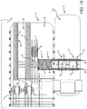
- bridge 13 is movable in direction D1 between a work position and a rest position, the latter not shown in Figure 18 .
- Each guide 25 is mounted on a block 58 fitted slidably to auxiliary structure 2, and which has an actuator for moving guide 25 both ways in direction D1.
- each block 58 is connected slidably to a respective guide 25 on platform 6.
- auxiliary structure 2 houses two reeling stations 7 and two assembly lines 8 parallel to each other.
- Transfer station 9 is also preferably double, and provides for loading/unloading two reels 1 onto/off bridge 13 even simultaneously.
- laying vessel 3 comprises two unreeling stations 11. More specifically, unreeling stations 11 are aligned in direction D1, so they can be served by one bridge 13.
- Bridge 13 in Figure 19 is longer than the ones described previously, since it has to define a double transfer station 9 along platform 6 and cater to two unreeling stations 11.
- auxiliary structure 2 may obviously comprise one reeling station and two transfer stations, or two reeling stations and one transfer station.
- the auxiliary structure may cater to a laying vessel with one or a number of unreeling stations.
- a single transfer station may be supplied in rapid succession with two reels fed along the bridge.
Landscapes
- Engineering & Computer Science (AREA)
- Mechanical Engineering (AREA)
- General Engineering & Computer Science (AREA)
- Combustion & Propulsion (AREA)
- Ocean & Marine Engineering (AREA)
- Chemical & Material Sciences (AREA)
- Bridges Or Land Bridges (AREA)
- Road Paving Structures (AREA)
- Storage Of Web-Like Or Filamentary Materials (AREA)
- Electric Cable Installation (AREA)
- Unwinding Of Filamentary Materials (AREA)
- Lift-Guide Devices, And Elevator Ropes And Cables (AREA)
- Conveying And Assembling Of Building Elements In Situ (AREA)
- Ship Loading And Unloading (AREA)
- Revetment (AREA)
Abstract
Description
- The present invention relates to a laying vessel for handling reels for laying elongated members on the bed of a body of water.
- More specifically, the present invention relates also to an auxiliary structure, a reel and a system and a method for handling reels.
- The present invention relates in general to the laying of elongated members on the bed of a body of water by means of a laying vessel. The elongated members, in this case underwater pipelines or cables, are composed of strings, each of which is wound on a reel, and is unwound gradually off the reel, from an unreeling station on board a laying vessel, and laid on the bed of the body of water as the laying vessel moves forward. One of the most critical aspects of this laying technique is feeding the strings to the laying vessel once the reel is unwound.
- When the reel is mounted in a fixed position on the laying vessel and the string is reeled off completely, the laying vessel returns to the quay to wind the reel with another string of the elongated member. The string is prefabricated at the quay and simultaneously wound onto the reel on the laying vessel. This operating method involves considerable, and costly, downtime of the laying vessel, which remains substantially idle the whole time the string is being prefabricated.
- To reduce downtime of the laying vessel,
Patent US 7,544,013 proposes prefabricating the strings on a floating auxiliary structure; winding the string onto a reel on the floating auxiliary structure; and transferring the string to a reel on the laying vessel, by unreeling the string off the reel on the floating auxiliary structure, and simultaneously reeling it onto the reel on the laying vessel. This method reduces the downtime involved in prefabricating the string, but not the time taken to transfer to string from one reel to another. - An alternative transfer method employs releasable reels that can be detached from the laying vessel, winds the reels in an auxiliary structure, and transfers the reels from the auxiliary structure to the laying vessel.
- In line with this operating method, document
WO 2011/105894 proposes prefabricating a number of reels; loading the reels onto the laying vessel; and positioning the reels successively at the unreeling station. The wound and unwound reels are loaded and unloaded respectively using cranes, which makes it difficult to position the reels accurately. It is important to bear in mind that these reels weigh thousands of tons, so handling them is a complex and also hazardous job, especially when they are suspended from a crane. A load suspended from a cable tends to swing, thus making it difficult to position, and also endangering any nearby personnel or structures. Moreover, handling the reels is made even more difficult by the crane being mounted on a floating unit. In fact, floating units equipped with cranes are invariably massive, precisely to ensure greater stability of the crane. - Documents
EP 302,038 WO 2009/077711 ,US 7,927,040 ,US 4,117,692 andGB 243,929 - It is an object of the present invention to provide a laying vessel designed to eliminate or at least reduce the drawbacks of the known art.
- According to the present invention there is provided a laying vessel for laying continuous elongated members unwound off reels, the laying vessel comprising a main deck; at least one unreeling station along the main deck comprising an unreeling device for supporting the reel for rotation;; a pit formed in the main deck, beneath the unreeling station; and an elevator housed in the pit to lift and lower the reels.
- This configuration allows raising and lowering the reel from below at the unreeling station without making use of cranes.
- In particular, the laying vessel comprises a support assembly for supporting a bridge for transferring reels.
- Making use of a bridge for the transfer of the reels renders the transfer safer.
- In particular, the support assembly comprises at least one heave compensating device.
- The heave compensation device improves stability of the bridge even in case of rough sea.
- In particular, the support assembly comprises two supports each comprising a supporting point for the bridge; the supporting point being located along the longitudinal plane of symmetry of the laying vessel.
- This configuration further reduces the oscillation of the bridge.
- In particular, the laying vessel comprises an elevator for lifting/releasing the reel off/onto the bridge and positioning the reel at the unreeling device.
- In this way the elevator can transfer the reels from the bridge to the unreeling device and viceversa.
- Another object of the present invention is to provide an auxiliary structure designed to eliminate or at least reduce the drawbacks of the known art.
- According to the present invention there is provided an auxiliary structure for handling reels for laying elongated members on the bed of a body of water, and in particular for transferring reels between the auxiliary structure and a laying vessel; the auxiliary structure comprising at least one bridge designed to connect the auxiliary structure and the laying vessel, and to guide the reels along a path extending over the auxiliary structure and the laying vessel; and the auxiliary structure being in particular a floating auxiliary structure, in particular a barge.
- In this way, cranes can be dispensed for the transfer to the reels.
- In particular, the bridge comprises two guides so as to offer two resting lines for the reel.
- In particular, the guides are movable between a work position, in which they are parallel to each other, with a given gauge, to define the bridge, and a rest position.
- The bridge is conveniently movable between a working position and a rest position.
- In particular, the guides are mounted on the auxiliary structure in sliding manner.
- This configuration allows changing the gauge of the guides between a position in which the guides define a support for the reel, and a position in which the guides do not interfere with the reel.
- In particular, the bridge comprises runners designed to run along the guides and support the reel for enhancing the advancement of the reels along the bridge and reducing friction.
- In particular, each runner has an actuator for lifting the top of the runner and the reel to enhance the transfer of the reels to and off the bridge.
- According to the present invention, it is convenient that the auxiliary structure has at least one reeling station for winding a string onto a reel.
- In this way, the transport path of the reels can be shortened.
- In particular, the auxiliary structure comprises at least one assembly line for assembling strings; said reeling station being aligned with the assembly line.
- In this way, it is easy to transfer strings to the auxiliary structure.
- In order to avoid the use of cranes for suspending the reels auxiliary structure has a transfer station for loading/unloading the reels onto/off the bridge; and a trolley movable between the reeling station and the transfer station; in particular, the trolley being designed for location underneath the bridge, and to allow the reel on the trolley to be loaded onto the bridge at the transfer station.
- A further object of the present invention is to provide a method for handling reels in order to eliminate or at least reduce the drawbacks of the known art.
- According to the present invention there is provided a method for handling reels for laying elongated members on the bed of a body of water, the method comprising the step of:
- winding the reels at a reeling station on a auxiliary structure;
- transferring the wound reels from the auxiliary structure to a laying vessel by means of a bridge;
- unwinding the reels at an unreeling station on the laying vessel; and
- transferring the empty reels from the laying vessel to the auxiliary structure.
- In this way, it is possible to realize a continuous path between the reeling station and the unreeling station and viceversa that allows dispensing from using cranes.
- It is an object of the present invention to provide a system for handling reels designed to eliminate or at least reduce the drawbacks of the known art.
- According to the present invention there is provided a system for handling reels for laying elongated members on the bed of a body of water, the system comprising:
- an auxiliary structure comprising a reeling station for winding the reels;
- a laying vessel comprising an unreeling station for unwinding the reels; and
- a bridge for transferring the wound reels from the auxiliary structure to the laying vessel and for transferring the empty reels from the laying vessel to the auxiliary structure.
- In this way a continuous path extends between the reeling station and the unreeling station.
- A further object of the present invention is to provide a reel for unwinding continuous elongated members and designed to eliminate or at least reduce the drawbacks of the known art.
- According to the present invention there is provided a reel for unwinding continuous elongated members on a bed of a body of water, wherein the reel has an axis of rotation, and comprises two grip points along the axis of rotation; and two facing retaining shoulders, which are configured to support the entire reel.
- The two grip points and the two facing retaining shoulders offer different support for the reel that allows transferring easily the reel.
- In particular, the outer edge of each retaining shoulder has two first supporting points, in particular recesses.
- In particular, the outer edge of each retaining shoulder has two second supporting points, in particular recesses.
- A non-limiting embodiment of the present invention will be described by way of example with reference to the attached drawings, in which :
-
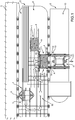
Figure 1 shows a plan view, with parts removed for clarity, of a reel handling system in accordance with the present invention and in a work configuration; -
Figure 2 shows a side view of a reel with parts removed for clarity; -
Figure 3 shows a partly sectioned elevation, with parts removed for clarity, of theFigure 2 reel; -
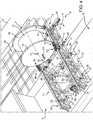
Figure 4 shows a view in perspective, with parts removed for clarity, of a detail of theFigure 1 handling system in a further work configuration; -
Figure 5 shows a partly sectioned elevation, with parts removed for clarity, of a detail of a reel transfer stage using the handling system according to the present invention; -
Figure 6 shows a partly sectioned elevation, with parts removed for clarity, of another stage in transferring theFigure 5 reel; -
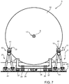
Figure 7 shows a larger-scale elevation, with parts removed for clarity, of a detail of theFigure 4 system; -
Figure 8 shows a view in perspective, with parts removed for clarity, of theFigure 1 system in a rest configuration; -
Figure 9 shows an elevation, with parts removed for clarity, of a detail inFigure 1 ; -
Figure 10 shows a section, with parts removed for clarity, of theFigure 9 detail along line X-X; -
Figure 11 shows a view in perspective, with parts removed for clarity, of a detail of theFigure 1 handling system; -
Figure 12 shows a plan view, with parts removed for clarity, of the system according to the present invention and with an alternative layout to that inFigure 1 ; -
Figure 13 shows a view in perspective, with parts removed for clarity, of a further layout of the system according to the present invention; -
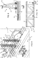
Figure 14 shows a partly sectioned elevation, with parts removed for clarity, of an alternative embodiment of the handling system according to the present invention; -
Figure 15 shows a partly sectioned elevation, with parts removed for clarity, of a detail of the alternative embodiment inFigure 14 ; -
Figure 16 shows a cross section, with parts removed for clarity, of a variation of the present invention; -
Figure 17 shows a longitudinal section, with parts removed for clarity, of theFigure 16 variation; -
Figure 18 shows a plan view, with parts removed for clarity, of a further variation of the present invention; -
Figure 19 shows a plan view, with parts removed for clarity, of a reel handling system in accordance with an alternative embodiment of the present invention. -
Figure 1 shows as a whole a system for handlingreels 1, and in particular for transferringreels 1 between anauxiliary structure 2 and a layingvessel 3. More specifically, the system according to the invention is designed to transferreels 1, wound withstrings 4 for forming an underwater pipeline (not shown in the drawings), fromauxiliary structure 2 to layingvessel 3, and to transfer unwoundreels 1 from layingvessel 3 toauxiliary structure 2.Reference number 1 indicates both wound and fully or partly unwound reels. - In the
Figure 1 layout,auxiliary structure 2 is a floating auxiliary structure, preferably a barge equipped with bumpers and drawn up alongside aquay 5 on one side, and alongside layingvessel 3 on the other. -
Auxiliary structure 2 has aplatform 6 supporting a reelingstation 7 for windingstrings 4 ontoreels 1; anassembly line 8 for assemblingstrings 4 or portions ofstrings 4; and atransfer station 9 for loading and unloadingreels 1.Auxiliary structure 2 also comprises paths extending alongplatform 6 to connect reelingstation 7,transfer station 9 and storage areas. - Laying
vessel 3 has amain deck 10; an unreelingstation 11 wherestrings 4 are unwound offreels 1; and apit 12 located at unreelingstation 11.Pit 12 is in the form of a recess, i.e. a hold, formed inmain deck 10. - The system comprises a
bridge 13 designed to connectauxiliary structure 2 and layingvessel 3; andactuators 14 for movingreel 1 alongbridge 13. -
Bridge 13 andreels 1 are designed so that onereel 1 at a time can be supported stably onbridge 13. - In the work position,
bridge 13 extends partly overplatform 6 and partly overmain deck 10 of layingvessel 3. - More specifically, in the work position,
bridge 13 extends fromtransfer station 9 to unreelingstation 11, which in fact are also the stations wherereels 1 are loaded/unloaded onto/offbridge 13. - Each
reel 1 has an axis of rotation A, and is designed to be moved alongbridge 13 in a direction D1 parallel to axis of rotation A. - In a variation not shown, the reel and bridge are designed to position the reel on the bridge with its axis of rotation crosswise to the guides, and to move the reel along the guides in a direction parallel to the guides and perpendicular to the axis of rotation of the reel.
- An important characteristic of the handling system according to the present invention is that each
reel 1 is transferred without having to be suspended from a crane. In point of fact,reel 1 is supported at all times. -
Reel 1 is an integral part of the handling system, and is in fact designed to cooperate with various component parts of the system to rest on various types of supports with which the system is equipped. - With reference to
Figures 2 and 3 , eachreel 1 comprises adrum 15; and two facing retainingshoulders 16 on opposite sides ofdrum 15. - Each
reel 1 is substantially defined by a cylindrical body extending about axis of rotation A. Strings 4 (Figure 1 ) are wound ontodrum 15, and are retained by retainingshoulders 16. In the present invention, retainingshoulders 16 also serve to support theentire reel 1 and relative string (Figure 1 ) when the reel is positioned resting on a support by the retaining shoulders. Consequently, retainingshoulders 16 are designed for this function. - With reference to
Figure 3 , eachreel 1 comprises two grip points 17 aligned along axis of rotation A. Eachgrip point 17 comprises an axial hole engaged by agripper 18 comprising a shaft. When grip points 17 are engaged by bothgrippers 18,reel 1 can be rotated about axis of rotation A by the shafts, or by at least one of the shafts, ofgrippers 18. - With reference to
Figure 2 , eachreel 1 has four supportingpoints 19, only two of which are shown inFigure 2 . The outer edge of each retainingshoulder 16 has two supportingpoints 19. Each supportingpoint 19 is substantially defined by a recess formed along the outer edge of retainingshoulder 16. The foursupporting points 19 have respective coplanar supporting faces 20; and respective retaining faces 21 coplanar in pairs. - Each
reel 1 has four supportingpoints 22, only two of which are shown inFigure 2 . The outer edge of each retainingshoulder 16 has two supportingpoints 22 located between the two supportingpoints 19. Each supportingpoint 22 is substantially defined by a recess formed in the outer edge of retainingshoulder 16. The foursupporting points 22 have respective coplanar supporting faces 23; and respective retaining faces 24 coplanar in pairs. - At reeling
station 7 and unreeling station 11 (Figure 1 ),reel 1 is supported at grip points 17. - On bridge 13 (
Figure 1 ), eachreel 1 is positioned resting on supportingpoints 19. - Each
reel 1 is positioned resting on supportingpoints 22 as it is transferred from reelingstation 7 to transferstation 9, and as it is transferred to unreelingstation 11 onboard laying vessel 3. -
Figure 4 showsbridge 13 in the work position, and anempty reel 1 resting onbridge 13 attransfer station 9. - More specifically,
bridge 13 comprises twoguides 25 which, in the work position, are parallel to each other, with a given gauge, and substantially horizontal. Eachguide 25 is hinged toplatform 6 about an axis A1 perpendicular to guide 25, and can be rotated selectively about axis A1. - More specifically, each
guide 25 is movable independently of the other. - Laying
vessel 3 comprises asupport assembly 26 for supportingbridge 13. More specifically,support assembly 26 is movable with respect tomain deck 10 to compensate for wave motion and reduce any oscillation ofbridge 13 induced by layingvessel 3. In the example shown,support assembly 26 comprises four controlled-yield compensating devices 27 located partly insidepit 12 and comprisingplates 28 projecting abovemain deck 10. Eachguide 25 rests on twoplates 28. -
Unreeling station 11 has an unreelingdevice 29 designed to gripreel 1 at grip points 17. Anelevator 30 is housed insidepit 12, substantially at unreelingstation 11, to unloadreel 1 offbridge 13, load real 1 ontobridge 13, andposition reel 1 at unreelingdevice 29. - As shown more clearly in
Figures 5 and 6 , unreelingdevice 29 comprises twoslides 31 mounted to slide with respect tomain deck 10 in a direction D1; and twogrippers 18 mounted on slides 31. In the present document, the term 'direction' is used in the sense of 'path', regardless of the actual direction. A direction indicated in the drawings is intended purely by way of example, and does not exclude the possibility of movement in the opposite direction to the one shown in the drawings. -
Unreeling device 29 comprises actuators, not shown in the attached drawings, for movingslides 31 andrespective grippers 18 towards and away from each other in two-way direction D1; and to rotate at least one ofgrippers 18. To transferreel 1 frombridge 13 to unreelingdevice 29,bridge 13 extends overpit 12, in whichelevator 30 is housed, and over unreelingdevice 29. - With reference to
Figure 5 ,elevator 30 comprises twouprights 32 fitted in sliding manner to the lateral walls ofpit 12; and aframe 33 connected touprights 32 and designed to engage areel 1 resting onbridge 13 at unreelingstation 11. In other words, when raisingelevator 30,frame 33 engagesreel 1 at supportingpoints 22, and raisesreel 1 with respect to bridge 13. - At this point,
bridge 13 is withdrawn, andelevator 30 is lowered insidepit 12 to align the axis of rotation A ofreel 1 withgrippers 18, which are activated to engage grip points 17 ofreel 1, as shown inFigure 6 . Oncereel 1 is engaged bygrippers 18,elevator 30 is lowered further to releaseframe 33 from supportingpoints 22 ofreel 1 and permit rotation ofreel 1. - With reference to
Figure 7 ,reels 1 are transported alongplatform 6 ofauxiliary structure 2 usingtrolleys 34. Eachtrolley 34 is designed to transport onereel 1 and to travel along paths laid out onplatform 6. In the example shown, the paths are defined by a grid of rails 35 (Figure 1 ). And eachtrolley 34 is designed to engage and travel along tworails 35. - Each
trolley 34 comprises aframe 36 designed to supportreel 1 at supportingpoints 22. -
Trolley 34 comprisesrunners 37 fitted torails 35, and cooperates with actuators 38 (Figure 11 ) designed to move along rails 35 and to engage and draw alongtrolley 34.Actuators 38 preferably comprise hydraulic jacks. -
Trolley 34 is sized to fit betweenguides 25 and to transferreel 1 fromtrolley 34 to bridge 13 and vice versa. -
Trolley 34 is capable of slight lifting movements by means ofactuators 39. -
Bridge 13 also comprisesrunners 40 fitted to and which run along guides 25.Runners 40 are preferably known types, and preferably of the type known as a Hilman rolling platform. In addition, eachrunner 40 comprises anactuator 41 designed to raise the top ofrunner 40 with respect to guide 25. In other words,reel 1 resting onbridge 13 is positioned resting on fourrunners 40 designed to run along guides 25. On enteringtransfer station 9 withreel 1,trolley 34positions supporting points 19 onrunners 40. By slightly raisingrunners 40,reel 1 can be lifted offtrolley 34 and transferred fromtrolley 34 to bridge 13. At this point,trolley 34 can be withdrawn fromtransfer station 9, and reel 1 lowered. - With reference to
Figure 4 ,actuators 14 are designed to draw or pushrunners 40 and therefore reel 1 alongbridge 13.Actuators 14 also preferably comprise hydraulicjacks engaging guides 25, and may also serve as a parking brake to holdrunners 40 andreel 1 in a given position. -
Figure 8 showsbridge 13 in a rest configuration, in which guides 25 are perpendicular toplatform 6. More specifically,bridge 13 comprises actuators, not shown, for rotatingguides 25 about axes A1 from theFigure 4 work configuration to the rest configuration, and vice versa. Moving from the work to the rest configuration by simply rotatingguides 25 about axes A1, however, is only possible when unreelingstation 11 is free ofreel 1. In fact, eachreel 1 is larger in diameter than the gauge ofguides 25, which is necessarily 'reduced' to provide adequate support forreel 1 resting onguides 25. As shown inFigure 8 , eachguide 25 is mounted on aslide 42, which is fitted toplatform 6 to slide in a direction perpendicular to guide 25. This way, the gauge ofguides 25 can be adjusted by means of anactuator 43. - With reference to
Figures 8 to 10 , eachguide 25 is defined by atrellis structure 44 with arail 45 on top.Trellis structure 44 is hinged at one end to slide 42 about axis A1, and haswheels 46 by which to roll alongplatform 6.Wheels 46 serve to reduce friction when altering the gauge ofguides 25 resting onplatform 6. - With reference to
Figure 11 , at reelingstation 7,auxiliary structure 2 comprises a reelingdevice 47, which in turn comprises twouprights 48 fixed toplatform 6, twoslides 49 fitted to the top of and movable in direction D1 with respect torespective uprights 48, and twogrippers 18 fitted to slides 49. To transfer areel 1 from atrolley 34 to reelingdevice 47,trolley 34 is inserted betweenuprights 48;reel 1 is gripped bygrippers 18; andtrolley 34 is lowered to permit rotation ofreel 1.Trolley 34 remains underneathreel 1 the whole time it is being wound. When winding of the reel is completed,trolley 34 is raised to support the weight ofreel 1, andgrippers 18 andrespective slides 49 are parted to releasegrippers 18 fromreel 1.Trolley 34 andreel 1 are now free to be removed from windingstation 7 and drawn byactuators 38 alongrails 35 to a holding/storage area. - With reference to
Figure 1 , to load awound reel 1 into avacant unreeling station 11 on layingvessel 3, layingvessel 3 is drawn up alongsideauxiliary structure 2, andbridge 13 is laid betweenauxiliary structure 2 and layingvessel 3. At this point,trolley 34 and thewound reel 1 are moved intotransfer station 9. As shown inFigure 7 , thewound reel 1 is transferred fromtrolley 34 to bridge 13 by raisingrunners 40. - Once transferred to bridge 13, the
wound reel 1 is moved in direction D1 into a position overpit 12 at unreelingstation 11. - As shown in
Figure 5 ,elevator 30lifts reel 1 offbridge 13. -
Guides 25 are parted to increase the gauge, and are rotated into a vertical position as shown inFigure 8 . - Next,
elevator 30 lowersreel 1 to set it, at least partly, into a position in which it can be gripped bygrippers 18. Oncereel 1 is gripped by unreelingdevice 29,elevator 30 is lowered further toclear reel 1 as it is being unreeled. - In the
Figure 12 variation, the handling system comprises twobridges 13, one connectingauxiliary structure 2 to layingvessel 3, and the other connectingauxiliary structure 2 toquay 5. - In the
Figure 13 variation,auxiliary structure 2 is positioned endwise with respect toquay 5, and has twobridges 13 projecting from opposite edges ofauxiliary structure 2 to serve two layingvessels 3 at the same time. - In the
Figure 14 embodiment,bridge 13 is simplified with respect to the embodiment in the preceding drawings. In this embodiment, runners 40 (Figures 4 and7 ) are omitted, and reel 1 slides along guides 25 ofbridge 13. To reduce friction betweenreel 1 and guides 25, guides 25 are greased, or Teflon panels are interposed betweenreel 1 and guides 25. - In the
Figure 14 embodiment, actuators 14 (Figure 4 ) are also replaced with anactuator 50 onauxiliary structure 2, and anactuator 51 on layingvessel 3. In the example shown,actuators respective cables eyelets 54 fitted to the outer faces of respective retaining shoulders 16. - To supply a
wound reel 1 to unreelingstation 11,actuator 51hauls reel 1 along guides 25 by means ofcable 53. - Conversely, to remove an unwound
reel 1 from unreelingstation 11,reel 1 is connected tocable 52. - In
Figure 14 ,reel 1 is connected to bothcables reel 1 in one drawing. - Eliminating runners 40 (
Figures 4 and7 ), which in the preceding embodiment also served to liftreel 1, makes it necessary to alter the way in whichreels 1 are transferred betweenbridge 13 andtrolley 34. - In
Figure 15 ,reel 1 rests on atrolley 34 comprisingactuators 55 for selectively lifting and loweringreel 1.Trolley 34 engagesreel 1 at supportingpoints 22, and is designed to liftreel 1 to position supporting points 19 overguides 25, and to lower faces 20 of supportingpoints 19 below the top surface ofguides 25 when the trolley disengages guides 25. - More specifically,
trolley 34 has fouractuators 55 designed to engage supportingpoints 22. - When a
reel 1 resting on atrolley 34 is positioned facingbridge 13,reel 1 is raised to allowtrolley 34 to move betweenguides 25 into the transfer station, with supportingpoints 19 positioned over guides 25. Next,reel 1 is lowered ontoguides 25. Andtrolley 34 at this point can be withdrawn fromtransfer station 9. - In the
Figure 16 and 17 variation, the compensating device is omitted, andbridge 13 is supported by asupport assembly 26 comprising two supports 56. Eachguide 25 ofbridge 13 is supported on a supportingpoint 57 of arespective support 56. Supportingpoint 57 is located along the longitudinal plane of symmetry P of layingvessel 3. In other words, each guide 25 simply rests on arespective support 56, and is free to oscillate and/or slide with respect to supportingpoint 57. The location of supportingpoint 57 along longitudinal plane of symmetry P reduces listing of layingvessel 3 induced bybridge 13 andreel 1. - As shown in
Figure 17 , supports 56 are preferably located insidepit 12, and are movable between a work position (shown by the continuous line), and a rest position (shown by the dash line), in which supports 56 allowreel 1 to be inserted freely insidepit 12. - In the
Figure 18 variation,bridge 13 is movable in direction D1 between a work position and a rest position, the latter not shown inFigure 18 . Eachguide 25 is mounted on ablock 58 fitted slidably toauxiliary structure 2, and which has an actuator for movingguide 25 both ways in direction D1. In other words, eachblock 58 is connected slidably to arespective guide 25 onplatform 6. - In the
Figure 19 embodiment,auxiliary structure 2 houses two reelingstations 7 and twoassembly lines 8 parallel to each other. -
Transfer station 9 is also preferably double, and provides for loading/unloading tworeels 1 onto/offbridge 13 even simultaneously. - In the
Figure 19 embodiment, layingvessel 3 comprises two unreelingstations 11. More specifically, unreelingstations 11 are aligned in direction D1, so they can be served by onebridge 13. -
Bridge 13 inFigure 19 is longer than the ones described previously, since it has to define adouble transfer station 9 alongplatform 6 and cater to two unreelingstations 11. - Clearly, other changes, not described herein, can be made to the present invention without, however, departing from the protective scope of the accompanying Claims.
- For example,
auxiliary structure 2 may obviously comprise one reeling station and two transfer stations, or two reeling stations and one transfer station. - Similarly, the auxiliary structure may cater to a laying vessel with one or a number of unreeling stations.
- A single transfer station may be supplied in rapid succession with two reels fed along the bridge.
Claims (24)
- A laying vessel for laying continuous elongated members unwound off reels, the laying vessel (3) comprising a main deck (10); at least one unreeling station (11) along the main deck (10) comprising an unreeling device (29) for supporting the reel (1) for rotation; a pit (12) formed in the main deck (10), beneath the unreeling station (11); and an elevator (30) housed in the pit (12) to lift and lower the reels (1).
- The laying vessel as claimed in Claim 1, wherein the laying vessel (3) comprises a support assembly (26) for supporting a bridge (13) for transferring reels, in particular the elevator (30) being configured for lifting/releasing the reel (1) off/onto the bridge (13) and positioning the reel (1) at the unreeling device (29).
- The laying vessel as claimed in Claim 2, wherein the support assembly (26) comprises at least one heave compensating device (27).
- The laying vessel as claimed in Claim 2 or 3, wherein the support assembly (26) comprises two supports (56) each comprising a supporting point (57) for the bridge (13); the supporting point (57) being located along the longitudinal plane of symmetry (P) of the laying vessel (3).
- An auxiliary structure for handling reels (1) for laying elongated members on the bed of a body of water, and in particular for transferring reels (1) between the auxiliary structure (2) and a laying vessel (3); the auxiliary structure (2) comprising at least one bridge (13) designed to connect the auxiliary structure (2) and the laying vessel (3), and to guide the reels (1) along a path extending over the auxiliary structure (2) and the laying vessel (3); and the auxiliary structure (2) being in particular a floating auxiliary structure, in particular a barge.
- The auxiliary structure as claimed in Claim 5, wherein the bridge (13) comprises two guides (25), in particular the guides (25) are mounted on the auxiliary structure (2) in sliding manner.
- The auxiliary structure as claimed in Claim 6, wherein the guides (25) are movable between a work position, in which they are parallel to each other, with a given gauge, to define the bridge (13), and a rest position, in particular the gauge of the guides (25) is variable between a position in which the guides define a support for the reel (1), and a position in which the guides do not interfere with the reel (1).
- The auxiliary structure as claimed in any one of the Claims from 5 to 7, wherein the bridge (13) comprises runners (40) designed to run along the guides (25) and support the reel (1), in particular each runner (40) has an actuator (41) for lifting the top of the runner (40) and the reel (1).
- The auxiliary structure as claimed in any one of the Claims from 5 to 8, wherein the auxiliary structure (2) has at least one reeling station (7) for winding a string (4) onto a reel (1), in particular the auxiliary structure (2) comprises at least one assembly line (8) for assembling strings (4); said reeling station (7) being aligned with the assembly line (8).
- The auxiliary structure as claimed in Claim 9, wherein the auxiliary structure (2) has a transfer station (9) for loading/unloading the reels (1) onto/off the bridge (13); and a trolley (34) movable between the reeling station (7) and the transfer station (9); in particular, the trolley (34) being designed for location underneath the bridge (13), and to allow the reel (1) on the trolley (34) to be loaded onto the bridge (13) at the transfer station (9).
- A method for handling reels (1) for laying elongated members on the bed of a body of water, the method comprising the step of:- winding the reels (1) at a reeling station (7) on a auxiliary structure (2);- transferring the wound reels (1) from the auxiliary structure (2) to a laying vessel (3) by means of a bridge (13);- unwinding the reels (1) at an unreeling station (11) on the laying vessel (3); and- transferring the empty reels (1) from the laying vessel (3) to the auxiliary structure (2).
- The method as claimed in Claim 11, and comprising the step of assembling strings (4) on an assembly line (8) on the auxiliary structure (2).
- The method as claimed in Claim 11 or 12, and comprising the step of moving the reels (1) between a transfer station (9), for loading/unloading the reels (1) onto/off the bridge (13), and the reeling station (7).
- The method as claimed in any one of Claims 11 to 13, wherein the auxiliary structure (2) is a floating auxiliary structure, preferably a barge.
- The method as claimed in any one of Claims 11 to 14, and comprising lifting/lowering the reel (1) by means of a trolley (34) beneath the reel (1) and/or a runners (40) beneath the reel (1) and/or an elevator (30) beneath the reel (1).
- A system for handling reels for laying elongated members on the bed of a body of water, the system comprising:- an auxiliary structure (2) comprising a reeling station (7) for winding the reels (1);- a laying vessel (3) comprising an unreeling station (11) for unwinding the reels (1); and- a bridge (13) for transferring the wound reels (1) from the auxiliary structure (2) to the laying vessel (3) and for transferring the empty reels (1) from the laying vessel (3) to the auxiliary structure (2).
- The system as claimed in Claim 16, and comprising an assembly line (8) on the auxiliary structure (2) for assembling strings (4).
- The system as claimed in Claim 16 or 17, and comprising runner (40) for moving the reels (1) along the auxiliary structure (2) between a transfer station (9), for loading/unloading the reels (1) onto/off the bridge (13), and the reeling station (7).
- The system as claimed in any one of Claims 16 to 18, wherein the auxiliary structure (2) is a floating auxiliary structure, preferably a barge.
- The system as claimed in any one of Claims 16 to 19, and comprising a trolley arranged beneath the reel (1) for lifting/lowering the reel (1).
- The system as claimed in any one of Claims 16 to 20, and comprising an elevator (30) arranged beneath the reel (1) for lifting/lowering the reel (1).
- A reel for unwinding continuous elongated members on a bed of a body of water, wherein the reel (1) has an axis of rotation (A), and comprises two grip points (17) along the axis of rotation (A); and two facing retaining shoulders (16), which are configured to support the entire reel (1).
- The reel as claimed in Claim 22, wherein the outer edge of each retaining shoulder (16) has two first supporting points (19), in particular recesses.
- The reel as claimed in Claim 22 or 23, wherein the outer edge of each retaining shoulder (16) has two second supporting points (22), in particular recesses.
Applications Claiming Priority (3)
| Application Number | Priority Date | Filing Date | Title |
|---|---|---|---|
| IT002049A ITMI20122049A1 (en) | 2012-11-30 | 2012-11-30 | SYSTEM AND METHOD OF MANIPULATION OF ROCKS ADJUSTABLE TO LAYING ELONGATED ELEMENTS ON A BED OF A WATER BODY, AUXILIARY STRUCTURE, AND INSTALLATION VESSEL |
| PCT/IB2013/060522 WO2014083547A2 (en) | 2012-11-30 | 2013-11-29 | System and method for handling reels for laying elongated members on the bed of a body of water, auxiliary structure, and laying vessel |
| EP13828817.0A EP2925596B1 (en) | 2012-11-30 | 2013-11-29 | System and method for handling reels for laying elongated members on the bed of a body of water, auxiliary structure, and laying vessel |
Related Parent Applications (2)
| Application Number | Title | Priority Date | Filing Date |
|---|---|---|---|
| EP13828817.0A Division-Into EP2925596B1 (en) | 2012-11-30 | 2013-11-29 | System and method for handling reels for laying elongated members on the bed of a body of water, auxiliary structure, and laying vessel |
| EP13828817.0A Division EP2925596B1 (en) | 2012-11-30 | 2013-11-29 | System and method for handling reels for laying elongated members on the bed of a body of water, auxiliary structure, and laying vessel |
Publications (4)
| Publication Number | Publication Date |
|---|---|
| EP3156317A2 true EP3156317A2 (en) | 2017-04-19 |
| EP3156317A3 EP3156317A3 (en) | 2017-08-09 |
| EP3156317B1 EP3156317B1 (en) | 2019-09-25 |
| EP3156317B8 EP3156317B8 (en) | 2019-11-13 |
Family
ID=47605627
Family Applications (2)
| Application Number | Title | Priority Date | Filing Date |
|---|---|---|---|
| EP16187172.8A Not-in-force EP3156317B8 (en) | 2012-11-30 | 2013-11-29 | Laying vessel |
| EP13828817.0A Not-in-force EP2925596B1 (en) | 2012-11-30 | 2013-11-29 | System and method for handling reels for laying elongated members on the bed of a body of water, auxiliary structure, and laying vessel |
Family Applications After (1)
| Application Number | Title | Priority Date | Filing Date |
|---|---|---|---|
| EP13828817.0A Not-in-force EP2925596B1 (en) | 2012-11-30 | 2013-11-29 | System and method for handling reels for laying elongated members on the bed of a body of water, auxiliary structure, and laying vessel |
Country Status (8)
| Country | Link |
|---|---|
| US (2) | US9567043B2 (en) |
| EP (2) | EP3156317B8 (en) |
| CN (1) | CN104812664B (en) |
| AU (1) | AU2013350760B2 (en) |
| BR (1) | BR112015012486B1 (en) |
| IT (1) | ITMI20122049A1 (en) |
| MY (1) | MY189200A (en) |
| WO (1) | WO2014083547A2 (en) |
Families Citing this family (6)
| Publication number | Priority date | Publication date | Assignee | Title |
|---|---|---|---|---|
| ITMI20122049A1 (en) * | 2012-11-30 | 2014-05-31 | Saipem Spa | SYSTEM AND METHOD OF MANIPULATION OF ROCKS ADJUSTABLE TO LAYING ELONGATED ELEMENTS ON A BED OF A WATER BODY, AUXILIARY STRUCTURE, AND INSTALLATION VESSEL |
| WO2016042071A1 (en) * | 2014-09-19 | 2016-03-24 | Itrec B.V. | Marine pipeline installation vessel and method for laying an offshore rigid pipeline in the sea |
| IT201600086514A1 (en) * | 2016-08-22 | 2018-02-22 | Saipem Spa | SYSTEM AND METHOD TO MOVE BETWEEN A LAYING VESSEL AND AN AUXILIARY PLATFORM ROCKS ADMITTED TO THE LAYING OF ELONGATED ELEMENTS ON A BED OF A WATER BODY |
| GB2554678A (en) * | 2016-10-03 | 2018-04-11 | Maats Tech Ltd | Reel drive apparatus |
| NL2018178B1 (en) * | 2017-01-16 | 2018-07-26 | Itrec Bv | Reel lay system, reel drive system and reel, and methods of use |
| CA3092070A1 (en) * | 2018-02-22 | 2019-08-29 | Trinity Bay Equipment Holdings, LLC | System and method for deploying coils of spoolable pipe |
Citations (7)
| Publication number | Priority date | Publication date | Assignee | Title |
|---|---|---|---|---|
| GB243929A (en) | 1925-02-05 | 1925-12-10 | Thomas Webster Parker | Improvements in and relating to the treatment of clay |
| US4117692A (en) | 1976-03-26 | 1978-10-03 | Karl Erik Oberg | Method and a system for producing and laying oil or gas pipelines on the sea bottom |
| EP0302038A1 (en) | 1987-07-27 | 1989-02-01 | Kvaerner Subsea Contracting A/S | A method for production and laying a pipeline or a cable under water |
| US7544013B2 (en) | 2002-12-30 | 2009-06-09 | Technip France | Installation for manufacturing wound rigid tubular pipes |
| WO2009077711A1 (en) | 2007-12-14 | 2009-06-25 | Saipem Uk Limited | A pipe laying apparatus and method |
| US7927040B2 (en) | 2008-08-08 | 2011-04-19 | Wilson Michael W N | Method for storing, delivering and spooling preassembled pipelines |
| WO2011105894A1 (en) | 2010-02-25 | 2011-09-01 | Itrec B.V. | Reel lay system |
Family Cites Families (23)
| Publication number | Priority date | Publication date | Assignee | Title |
|---|---|---|---|---|
| US3591023A (en) * | 1969-01-30 | 1971-07-06 | Rudolph Allen | Mechanically programmable marine transport cargo handling and stowage system |
| FR2120495A5 (en) * | 1971-01-06 | 1972-08-18 | Creusot Loire | |
| FR2268686A1 (en) * | 1974-04-24 | 1975-11-21 | Mac Gregor Comarain Sa | Goods transfer system between ships - uses hinged beams with universal flexibility and slide movement |
| US4274799A (en) * | 1978-02-16 | 1981-06-23 | Martech International, Inc. | Method and apparatus for reeling pipeline |
| US4269540A (en) * | 1978-05-05 | 1981-05-26 | Santa Fe International Corporation | Self propelled dynamically positioned reel pipe laying ship |
| US4260287A (en) * | 1978-05-24 | 1981-04-07 | Santa Fe International Corporation | Portable reel pipelaying method |
| US4480757A (en) * | 1982-01-28 | 1984-11-06 | Amca International Corporation | Collapsible frame support for pivotal boom on a portable crane |
| US7341422B1 (en) * | 1998-04-08 | 2008-03-11 | Trailer Bridge, Inc. | Container transportation system and method |
| FI20002713A0 (en) * | 1999-12-30 | 2000-12-11 | Oy Langh Ship Ab | Procedure and arrangement for transporting rolls of ships, intermediate decks and intermediate decks in a cargo hold |
| US20050006516A1 (en) * | 2003-07-02 | 2005-01-13 | Tsann Kuen Enterprise Co. | Wire winding device for electrical appliances |
| GB0715527D0 (en) * | 2007-08-10 | 2007-09-19 | Acergy Uk Ltd | Methods & apparatus for transferring and laying elongate articles at sea |
| WO2010033083A1 (en) * | 2008-09-19 | 2010-03-25 | Keppel Offshore & Marine Technology Centre Pte Ltd | Cargo transfer system |
| BRPI1012782A2 (en) * | 2009-05-22 | 2018-03-13 | Wellstream International Limited | transport and installation of hose |
| CN102020003B (en) * | 2009-09-16 | 2013-05-15 | 上海利策科技股份有限公司 | Reel-type submarine pipeline laying workboat and working method thereof |
| CN102039988B (en) * | 2009-10-15 | 2013-08-14 | 上海利策科技股份有限公司 | Deep-water seafloor pipe laying work boat with self-installing winding drum and work method thereof |
| US8608406B2 (en) * | 2010-03-05 | 2013-12-17 | J. Ray Mcdermott, S.A. | Landing mechanism for lifted pipe reel |
| NO20110989A1 (en) * | 2010-09-30 | 2012-04-02 | Kongsberg Oil & Gas Technologies As | Apparatus and method for laying an elongate element from a vessel |
| US20120148348A1 (en) * | 2010-12-14 | 2012-06-14 | Lylyn Hingle Stockstill | System for reeling pipeline |
| NL2007064C2 (en) * | 2011-07-07 | 2013-01-08 | Itrec Bv | Shear leg crane and transportation vessel. |
| US20130087650A1 (en) * | 2011-10-07 | 2013-04-11 | Lee David Screaton | Flexible Product Reel Cartridge |
| GB201119549D0 (en) * | 2011-11-14 | 2011-12-28 | Skagerak Engineering As | A storage and deployment unit for a coilable element and a method of handling a coilable element |
| GB201200127D0 (en) * | 2012-01-05 | 2012-02-15 | Saipem Spa | Laying of conduit at sea using horizontal reels |
| ITMI20122049A1 (en) * | 2012-11-30 | 2014-05-31 | Saipem Spa | SYSTEM AND METHOD OF MANIPULATION OF ROCKS ADJUSTABLE TO LAYING ELONGATED ELEMENTS ON A BED OF A WATER BODY, AUXILIARY STRUCTURE, AND INSTALLATION VESSEL |
-
2012
- 2012-11-30 IT IT002049A patent/ITMI20122049A1/en unknown
-
2013
- 2013-11-29 MY MYPI2015001423A patent/MY189200A/en unknown
- 2013-11-29 BR BR112015012486-0A patent/BR112015012486B1/en not_active IP Right Cessation
- 2013-11-29 EP EP16187172.8A patent/EP3156317B8/en not_active Not-in-force
- 2013-11-29 WO PCT/IB2013/060522 patent/WO2014083547A2/en not_active Ceased
- 2013-11-29 EP EP13828817.0A patent/EP2925596B1/en not_active Not-in-force
- 2013-11-29 CN CN201380062350.4A patent/CN104812664B/en not_active Expired - Fee Related
- 2013-11-29 US US14/646,664 patent/US9567043B2/en not_active Expired - Fee Related
- 2013-11-29 AU AU2013350760A patent/AU2013350760B2/en not_active Ceased
-
2017
- 2017-01-24 US US15/413,927 patent/US10024461B2/en active Active
Patent Citations (7)
| Publication number | Priority date | Publication date | Assignee | Title |
|---|---|---|---|---|
| GB243929A (en) | 1925-02-05 | 1925-12-10 | Thomas Webster Parker | Improvements in and relating to the treatment of clay |
| US4117692A (en) | 1976-03-26 | 1978-10-03 | Karl Erik Oberg | Method and a system for producing and laying oil or gas pipelines on the sea bottom |
| EP0302038A1 (en) | 1987-07-27 | 1989-02-01 | Kvaerner Subsea Contracting A/S | A method for production and laying a pipeline or a cable under water |
| US7544013B2 (en) | 2002-12-30 | 2009-06-09 | Technip France | Installation for manufacturing wound rigid tubular pipes |
| WO2009077711A1 (en) | 2007-12-14 | 2009-06-25 | Saipem Uk Limited | A pipe laying apparatus and method |
| US7927040B2 (en) | 2008-08-08 | 2011-04-19 | Wilson Michael W N | Method for storing, delivering and spooling preassembled pipelines |
| WO2011105894A1 (en) | 2010-02-25 | 2011-09-01 | Itrec B.V. | Reel lay system |
Also Published As
| Publication number | Publication date |
|---|---|
| BR112015012486B1 (en) | 2022-05-03 |
| WO2014083547A3 (en) | 2014-11-06 |
| EP2925596B1 (en) | 2016-11-02 |
| BR112015012486A2 (en) | 2017-07-11 |
| EP2925596A2 (en) | 2015-10-07 |
| CN104812664B (en) | 2017-06-06 |
| AU2013350760A1 (en) | 2015-05-21 |
| EP3156317B1 (en) | 2019-09-25 |
| AU2013350760B2 (en) | 2017-04-20 |
| US9567043B2 (en) | 2017-02-14 |
| US20170159848A1 (en) | 2017-06-08 |
| MY189200A (en) | 2022-01-31 |
| US20150298773A1 (en) | 2015-10-22 |
| EP3156317B8 (en) | 2019-11-13 |
| US10024461B2 (en) | 2018-07-17 |
| CN104812664A (en) | 2015-07-29 |
| WO2014083547A9 (en) | 2015-05-28 |
| EP3156317A3 (en) | 2017-08-09 |
| WO2014083547A2 (en) | 2014-06-05 |
| ITMI20122049A1 (en) | 2014-05-31 |
Similar Documents
| Publication | Publication Date | Title |
|---|---|---|
| US10024461B2 (en) | System and method for handling reels for laying elongated members on the bed of a body of water, auxiliary structure, and laying vessel | |
| US3877583A (en) | Pipe racking system | |
| US9315244B2 (en) | Hold crane as well as pipefeeder vessel with such hold crane | |
| EP3580121A1 (en) | Upending device for upending an elongate support structure | |
| US20170327325A1 (en) | Horse And Saddle Transfer Apparatus For Shipping Containers And Method Of Operation | |
| AU696616B2 (en) | Device for winding up or unwinding elongated flexible articles | |
| NL2011391C2 (en) | Method for arranging a pile on a vessel. | |
| EP3478566B1 (en) | System and method | |
| JPH0444714Y2 (en) | ||
| NL2008456C2 (en) | Improved reeling system. | |
| JPH0444712Y2 (en) | ||
| EP3500484B1 (en) | System and method for moving between a laying vessel and an auxilary platform reels configured for laying elongated members on a bed of a body of water | |
| WO2024018024A1 (en) | Monopiles transport and installation vessel | |
| WO2025083243A1 (en) | Vessel for upending and/or installing of a foundation pile | |
| CN121085153A (en) | Double-arm frame gantry crane with submarine cable conveying function | |
| NL2013570B1 (en) | End fitting handling in a marine pipeline installation system. | |
| CN121448903A (en) | Portal crane with submarine cable conveying function | |
| JPH0444713Y2 (en) | ||
| JP2007269426A (en) | Container crane hoisting mechanism | |
| WO2018093253A1 (en) | Tender assisted drilling system comprising a high-line system, method for transferring tubulars using such a system and method of installing such a system |
Legal Events
| Date | Code | Title | Description |
|---|---|---|---|
| PUAI | Public reference made under article 153(3) epc to a published international application that has entered the european phase |
Free format text: ORIGINAL CODE: 0009012 |
|
| STAA | Information on the status of an ep patent application or granted ep patent |
Free format text: STATUS: THE APPLICATION HAS BEEN PUBLISHED |
|
| AC | Divisional application: reference to earlier application |
Ref document number: 2925596 Country of ref document: EP Kind code of ref document: P |
|
| AK | Designated contracting states |
Kind code of ref document: A2 Designated state(s): AL AT BE BG CH CY CZ DE DK EE ES FI FR GB GR HR HU IE IS IT LI LT LU LV MC MK MT NL NO PL PT RO RS SE SI SK SM TR |
|
| PUAL | Search report despatched |
Free format text: ORIGINAL CODE: 0009013 |
|
| AK | Designated contracting states |
Kind code of ref document: A3 Designated state(s): AL AT BE BG CH CY CZ DE DK EE ES FI FR GB GR HR HU IE IS IT LI LT LU LV MC MK MT NL NO PL PT RO RS SE SI SK SM TR |
|
| RIC1 | Information provided on ipc code assigned before grant |
Ipc: B63B 27/30 20060101AFI20170704BHEP Ipc: F16L 1/20 20060101ALI20170704BHEP Ipc: B63B 35/03 20060101ALI20170704BHEP |
|
| STAA | Information on the status of an ep patent application or granted ep patent |
Free format text: STATUS: REQUEST FOR EXAMINATION WAS MADE |
|
| 17P | Request for examination filed |
Effective date: 20180208 |
|
| RBV | Designated contracting states (corrected) |
Designated state(s): AL AT BE BG CH CY CZ DE DK EE ES FI FR GB GR HR HU IE IS IT LI LT LU LV MC MK MT NL NO PL PT RO RS SE SI SK SM TR |
|
| STAA | Information on the status of an ep patent application or granted ep patent |
Free format text: STATUS: EXAMINATION IS IN PROGRESS |
|
| 17Q | First examination report despatched |
Effective date: 20180503 |
|
| GRAP | Despatch of communication of intention to grant a patent |
Free format text: ORIGINAL CODE: EPIDOSNIGR1 |
|
| STAA | Information on the status of an ep patent application or granted ep patent |
Free format text: STATUS: GRANT OF PATENT IS INTENDED |
|
| INTG | Intention to grant announced |
Effective date: 20190417 |
|
| GRAS | Grant fee paid |
Free format text: ORIGINAL CODE: EPIDOSNIGR3 |
|
| GRAA | (expected) grant |
Free format text: ORIGINAL CODE: 0009210 |
|
| STAA | Information on the status of an ep patent application or granted ep patent |
Free format text: STATUS: THE PATENT HAS BEEN GRANTED |
|
| AC | Divisional application: reference to earlier application |
Ref document number: 2925596 Country of ref document: EP Kind code of ref document: P |
|
| AK | Designated contracting states |
Kind code of ref document: B1 Designated state(s): AL AT BE BG CH CY CZ DE DK EE ES FI FR GB GR HR HU IE IS IT LI LT LU LV MC MK MT NL NO PL PT RO RS SE SI SK SM TR |
|
| REG | Reference to a national code |
Ref country code: GB Ref legal event code: FG4D |
|
| REG | Reference to a national code |
Ref country code: CH Ref legal event code: EP |
|
| REG | Reference to a national code |
Ref country code: CH Ref legal event code: PK Free format text: TITEL Ref country code: AT Ref legal event code: REF Ref document number: 1183576 Country of ref document: AT Kind code of ref document: T Effective date: 20191015 |
|
| REG | Reference to a national code |
Ref country code: IE Ref legal event code: FG4D |
|
| REG | Reference to a national code |
Ref country code: DE Ref legal event code: R096 Ref document number: 602013061120 Country of ref document: DE |
|
| REG | Reference to a national code |
Ref country code: NL Ref legal event code: FP |
|
| REG | Reference to a national code |
Ref country code: CH Ref legal event code: PK Free format text: BERICHTIGUNG B8 |
|
| REG | Reference to a national code |
Ref country code: NO Ref legal event code: T2 Effective date: 20190925 |
|
| PG25 | Lapsed in a contracting state [announced via postgrant information from national office to epo] |
Ref country code: SE Free format text: LAPSE BECAUSE OF FAILURE TO SUBMIT A TRANSLATION OF THE DESCRIPTION OR TO PAY THE FEE WITHIN THE PRESCRIBED TIME-LIMIT Effective date: 20190925 Ref country code: BG Free format text: LAPSE BECAUSE OF FAILURE TO SUBMIT A TRANSLATION OF THE DESCRIPTION OR TO PAY THE FEE WITHIN THE PRESCRIBED TIME-LIMIT Effective date: 20191225 Ref country code: FI Free format text: LAPSE BECAUSE OF FAILURE TO SUBMIT A TRANSLATION OF THE DESCRIPTION OR TO PAY THE FEE WITHIN THE PRESCRIBED TIME-LIMIT Effective date: 20190925 Ref country code: HR Free format text: LAPSE BECAUSE OF FAILURE TO SUBMIT A TRANSLATION OF THE DESCRIPTION OR TO PAY THE FEE WITHIN THE PRESCRIBED TIME-LIMIT Effective date: 20190925 Ref country code: LT Free format text: LAPSE BECAUSE OF FAILURE TO SUBMIT A TRANSLATION OF THE DESCRIPTION OR TO PAY THE FEE WITHIN THE PRESCRIBED TIME-LIMIT Effective date: 20190925 |
|
| REG | Reference to a national code |
Ref country code: LT Ref legal event code: MG4D |
|
| PG25 | Lapsed in a contracting state [announced via postgrant information from national office to epo] |
Ref country code: GR Free format text: LAPSE BECAUSE OF FAILURE TO SUBMIT A TRANSLATION OF THE DESCRIPTION OR TO PAY THE FEE WITHIN THE PRESCRIBED TIME-LIMIT Effective date: 20191226 Ref country code: LV Free format text: LAPSE BECAUSE OF FAILURE TO SUBMIT A TRANSLATION OF THE DESCRIPTION OR TO PAY THE FEE WITHIN THE PRESCRIBED TIME-LIMIT Effective date: 20190925 Ref country code: RS Free format text: LAPSE BECAUSE OF FAILURE TO SUBMIT A TRANSLATION OF THE DESCRIPTION OR TO PAY THE FEE WITHIN THE PRESCRIBED TIME-LIMIT Effective date: 20190925 |
|
| REG | Reference to a national code |
Ref country code: AT Ref legal event code: MK05 Ref document number: 1183576 Country of ref document: AT Kind code of ref document: T Effective date: 20190925 |
|
| PG25 | Lapsed in a contracting state [announced via postgrant information from national office to epo] |
Ref country code: ES Free format text: LAPSE BECAUSE OF FAILURE TO SUBMIT A TRANSLATION OF THE DESCRIPTION OR TO PAY THE FEE WITHIN THE PRESCRIBED TIME-LIMIT Effective date: 20190925 Ref country code: PT Free format text: LAPSE BECAUSE OF FAILURE TO SUBMIT A TRANSLATION OF THE DESCRIPTION OR TO PAY THE FEE WITHIN THE PRESCRIBED TIME-LIMIT Effective date: 20200127 Ref country code: AL Free format text: LAPSE BECAUSE OF FAILURE TO SUBMIT A TRANSLATION OF THE DESCRIPTION OR TO PAY THE FEE WITHIN THE PRESCRIBED TIME-LIMIT Effective date: 20190925 Ref country code: PL Free format text: LAPSE BECAUSE OF FAILURE TO SUBMIT A TRANSLATION OF THE DESCRIPTION OR TO PAY THE FEE WITHIN THE PRESCRIBED TIME-LIMIT Effective date: 20190925 Ref country code: EE Free format text: LAPSE BECAUSE OF FAILURE TO SUBMIT A TRANSLATION OF THE DESCRIPTION OR TO PAY THE FEE WITHIN THE PRESCRIBED TIME-LIMIT Effective date: 20190925 Ref country code: RO Free format text: LAPSE BECAUSE OF FAILURE TO SUBMIT A TRANSLATION OF THE DESCRIPTION OR TO PAY THE FEE WITHIN THE PRESCRIBED TIME-LIMIT Effective date: 20190925 Ref country code: AT Free format text: LAPSE BECAUSE OF FAILURE TO SUBMIT A TRANSLATION OF THE DESCRIPTION OR TO PAY THE FEE WITHIN THE PRESCRIBED TIME-LIMIT Effective date: 20190925 |
|
| PG25 | Lapsed in a contracting state [announced via postgrant information from national office to epo] |
Ref country code: IS Free format text: LAPSE BECAUSE OF FAILURE TO SUBMIT A TRANSLATION OF THE DESCRIPTION OR TO PAY THE FEE WITHIN THE PRESCRIBED TIME-LIMIT Effective date: 20200224 Ref country code: CZ Free format text: LAPSE BECAUSE OF FAILURE TO SUBMIT A TRANSLATION OF THE DESCRIPTION OR TO PAY THE FEE WITHIN THE PRESCRIBED TIME-LIMIT Effective date: 20190925 Ref country code: SK Free format text: LAPSE BECAUSE OF FAILURE TO SUBMIT A TRANSLATION OF THE DESCRIPTION OR TO PAY THE FEE WITHIN THE PRESCRIBED TIME-LIMIT Effective date: 20190925 Ref country code: SM Free format text: LAPSE BECAUSE OF FAILURE TO SUBMIT A TRANSLATION OF THE DESCRIPTION OR TO PAY THE FEE WITHIN THE PRESCRIBED TIME-LIMIT Effective date: 20190925 |
|
| REG | Reference to a national code |
Ref country code: DE Ref legal event code: R119 Ref document number: 602013061120 Country of ref document: DE |
|
| REG | Reference to a national code |
Ref country code: CH Ref legal event code: PL |
|
| PG2D | Information on lapse in contracting state deleted |
Ref country code: IS |
|
| PG25 | Lapsed in a contracting state [announced via postgrant information from national office to epo] |
Ref country code: DK Free format text: LAPSE BECAUSE OF FAILURE TO SUBMIT A TRANSLATION OF THE DESCRIPTION OR TO PAY THE FEE WITHIN THE PRESCRIBED TIME-LIMIT Effective date: 20190925 Ref country code: CH Free format text: LAPSE BECAUSE OF NON-PAYMENT OF DUE FEES Effective date: 20191130 Ref country code: LI Free format text: LAPSE BECAUSE OF NON-PAYMENT OF DUE FEES Effective date: 20191130 Ref country code: MC Free format text: LAPSE BECAUSE OF FAILURE TO SUBMIT A TRANSLATION OF THE DESCRIPTION OR TO PAY THE FEE WITHIN THE PRESCRIBED TIME-LIMIT Effective date: 20190925 Ref country code: LU Free format text: LAPSE BECAUSE OF NON-PAYMENT OF DUE FEES Effective date: 20191129 Ref country code: IS Free format text: LAPSE BECAUSE OF FAILURE TO SUBMIT A TRANSLATION OF THE DESCRIPTION OR TO PAY THE FEE WITHIN THE PRESCRIBED TIME-LIMIT Effective date: 20200126 |
|
| PLBE | No opposition filed within time limit |
Free format text: ORIGINAL CODE: 0009261 |
|
| STAA | Information on the status of an ep patent application or granted ep patent |
Free format text: STATUS: NO OPPOSITION FILED WITHIN TIME LIMIT |
|
| REG | Reference to a national code |
Ref country code: BE Ref legal event code: MM Effective date: 20191130 |
|
| 26N | No opposition filed |
Effective date: 20200626 |
|
| PG25 | Lapsed in a contracting state [announced via postgrant information from national office to epo] |
Ref country code: IE Free format text: LAPSE BECAUSE OF NON-PAYMENT OF DUE FEES Effective date: 20191129 Ref country code: DE Free format text: LAPSE BECAUSE OF NON-PAYMENT OF DUE FEES Effective date: 20200603 |
|
| PG25 | Lapsed in a contracting state [announced via postgrant information from national office to epo] |
Ref country code: BE Free format text: LAPSE BECAUSE OF NON-PAYMENT OF DUE FEES Effective date: 20191130 Ref country code: SI Free format text: LAPSE BECAUSE OF FAILURE TO SUBMIT A TRANSLATION OF THE DESCRIPTION OR TO PAY THE FEE WITHIN THE PRESCRIBED TIME-LIMIT Effective date: 20190925 |
|
| PG25 | Lapsed in a contracting state [announced via postgrant information from national office to epo] |
Ref country code: CY Free format text: LAPSE BECAUSE OF FAILURE TO SUBMIT A TRANSLATION OF THE DESCRIPTION OR TO PAY THE FEE WITHIN THE PRESCRIBED TIME-LIMIT Effective date: 20190925 |
|
| PG25 | Lapsed in a contracting state [announced via postgrant information from national office to epo] |
Ref country code: HU Free format text: LAPSE BECAUSE OF FAILURE TO SUBMIT A TRANSLATION OF THE DESCRIPTION OR TO PAY THE FEE WITHIN THE PRESCRIBED TIME-LIMIT; INVALID AB INITIO Effective date: 20131129 Ref country code: MT Free format text: LAPSE BECAUSE OF FAILURE TO SUBMIT A TRANSLATION OF THE DESCRIPTION OR TO PAY THE FEE WITHIN THE PRESCRIBED TIME-LIMIT Effective date: 20190925 |
|
| PGFP | Annual fee paid to national office [announced via postgrant information from national office to epo] |
Ref country code: NO Payment date: 20211118 Year of fee payment: 9 Ref country code: FR Payment date: 20211126 Year of fee payment: 9 Ref country code: GB Payment date: 20211123 Year of fee payment: 9 Ref country code: NL Payment date: 20211125 Year of fee payment: 9 |
|
| PGFP | Annual fee paid to national office [announced via postgrant information from national office to epo] |
Ref country code: IT Payment date: 20211119 Year of fee payment: 9 |
|
| PG25 | Lapsed in a contracting state [announced via postgrant information from national office to epo] |
Ref country code: TR Free format text: LAPSE BECAUSE OF FAILURE TO SUBMIT A TRANSLATION OF THE DESCRIPTION OR TO PAY THE FEE WITHIN THE PRESCRIBED TIME-LIMIT Effective date: 20190925 |
|
| PG25 | Lapsed in a contracting state [announced via postgrant information from national office to epo] |
Ref country code: MK Free format text: LAPSE BECAUSE OF FAILURE TO SUBMIT A TRANSLATION OF THE DESCRIPTION OR TO PAY THE FEE WITHIN THE PRESCRIBED TIME-LIMIT Effective date: 20190925 |
|
| REG | Reference to a national code |
Ref country code: NO Ref legal event code: MMEP |
|
| REG | Reference to a national code |
Ref country code: NL Ref legal event code: MM Effective date: 20221201 |
|
| GBPC | Gb: european patent ceased through non-payment of renewal fee |
Effective date: 20221129 |
|
| PG25 | Lapsed in a contracting state [announced via postgrant information from national office to epo] |
Ref country code: NO Free format text: LAPSE BECAUSE OF NON-PAYMENT OF DUE FEES Effective date: 20221130 |
|
| PG25 | Lapsed in a contracting state [announced via postgrant information from national office to epo] |
Ref country code: NL Free format text: LAPSE BECAUSE OF NON-PAYMENT OF DUE FEES Effective date: 20221201 |
|
| PG25 | Lapsed in a contracting state [announced via postgrant information from national office to epo] |
Ref country code: IT Free format text: LAPSE BECAUSE OF NON-PAYMENT OF DUE FEES Effective date: 20221129 Ref country code: GB Free format text: LAPSE BECAUSE OF NON-PAYMENT OF DUE FEES Effective date: 20221129 |
|
| PG25 | Lapsed in a contracting state [announced via postgrant information from national office to epo] |
Ref country code: FR Free format text: LAPSE BECAUSE OF NON-PAYMENT OF DUE FEES Effective date: 20221130 |