EP3156307A1 - Work vehicles with cylinder cushioning arrangement - Google Patents
Work vehicles with cylinder cushioning arrangement Download PDFInfo
- Publication number
- EP3156307A1 EP3156307A1 EP16193342.9A EP16193342A EP3156307A1 EP 3156307 A1 EP3156307 A1 EP 3156307A1 EP 16193342 A EP16193342 A EP 16193342A EP 3156307 A1 EP3156307 A1 EP 3156307A1
- Authority
- EP
- European Patent Office
- Prior art keywords
- hydraulic cylinder
- cylinder
- end port
- hydraulic
- frame member
- Prior art date
- Legal status (The legal status is an assumption and is not a legal conclusion. Google has not performed a legal analysis and makes no representation as to the accuracy of the status listed.)
- Withdrawn
Links
- 239000012530 fluid Substances 0.000 claims abstract description 50
- 230000008878 coupling Effects 0.000 claims description 4
- 238000010168 coupling process Methods 0.000 claims description 4
- 238000005859 coupling reaction Methods 0.000 claims description 4
- 238000013459 approach Methods 0.000 description 4
- 230000001668 ameliorated effect Effects 0.000 description 2
- 238000010276 construction Methods 0.000 description 2
- 238000013016 damping Methods 0.000 description 2
- 230000001360 synchronised effect Effects 0.000 description 1
Images


Classifications
-
- B—PERFORMING OPERATIONS; TRANSPORTING
- B60—VEHICLES IN GENERAL
- B60G—VEHICLE SUSPENSION ARRANGEMENTS
- B60G17/00—Resilient suspensions having means for adjusting the spring or vibration-damper characteristics, for regulating the distance between a supporting surface and a sprung part of vehicle or for locking suspension during use to meet varying vehicular or surface conditions, e.g. due to speed or load
- B60G17/02—Spring characteristics, e.g. mechanical springs and mechanical adjusting means
- B60G17/04—Spring characteristics, e.g. mechanical springs and mechanical adjusting means fluid spring characteristics
-
- B—PERFORMING OPERATIONS; TRANSPORTING
- B62—LAND VEHICLES FOR TRAVELLING OTHERWISE THAN ON RAILS
- B62D—MOTOR VEHICLES; TRAILERS
- B62D5/00—Power-assisted or power-driven steering
- B62D5/06—Power-assisted or power-driven steering fluid, i.e. using a pressurised fluid for most or all the force required for steering a vehicle
- B62D5/10—Power-assisted or power-driven steering fluid, i.e. using a pressurised fluid for most or all the force required for steering a vehicle characterised by type of power unit
- B62D5/12—Piston and cylinder
-
- A—HUMAN NECESSITIES
- A01—AGRICULTURE; FORESTRY; ANIMAL HUSBANDRY; HUNTING; TRAPPING; FISHING
- A01B—SOIL WORKING IN AGRICULTURE OR FORESTRY; PARTS, DETAILS, OR ACCESSORIES OF AGRICULTURAL MACHINES OR IMPLEMENTS, IN GENERAL
- A01B59/00—Devices specially adapted for connection between animals or tractors and agricultural machines or implements
- A01B59/04—Devices specially adapted for connection between animals or tractors and agricultural machines or implements for machines pulled or pushed by a tractor
- A01B59/041—Devices specially adapted for connection between animals or tractors and agricultural machines or implements for machines pulled or pushed by a tractor preventing or limiting side-play of implements
- A01B59/0415—Devices specially adapted for connection between animals or tractors and agricultural machines or implements for machines pulled or pushed by a tractor preventing or limiting side-play of implements by hydraulic or pneumatic means acting on the lower draft links
-
- B—PERFORMING OPERATIONS; TRANSPORTING
- B60—VEHICLES IN GENERAL
- B60G—VEHICLE SUSPENSION ARRANGEMENTS
- B60G11/00—Resilient suspensions characterised by arrangement, location or kind of springs
- B60G11/26—Resilient suspensions characterised by arrangement, location or kind of springs having fluid springs only, e.g. hydropneumatic springs
- B60G11/265—Resilient suspensions characterised by arrangement, location or kind of springs having fluid springs only, e.g. hydropneumatic springs hydraulic springs
-
- B—PERFORMING OPERATIONS; TRANSPORTING
- B62—LAND VEHICLES FOR TRAVELLING OTHERWISE THAN ON RAILS
- B62D—MOTOR VEHICLES; TRAILERS
- B62D12/00—Steering specially adapted for vehicles operating in tandem or having pivotally connected frames
-
- F—MECHANICAL ENGINEERING; LIGHTING; HEATING; WEAPONS; BLASTING
- F16—ENGINEERING ELEMENTS AND UNITS; GENERAL MEASURES FOR PRODUCING AND MAINTAINING EFFECTIVE FUNCTIONING OF MACHINES OR INSTALLATIONS; THERMAL INSULATION IN GENERAL
- F16F—SPRINGS; SHOCK-ABSORBERS; MEANS FOR DAMPING VIBRATION
- F16F9/00—Springs, vibration-dampers, shock-absorbers, or similarly-constructed movement-dampers using a fluid or the equivalent as damping medium
- F16F9/32—Details
- F16F9/48—Arrangements for providing different damping effects at different parts of the stroke
- F16F9/49—Stops limiting fluid passage, e.g. hydraulic stops or elastomeric elements inside the cylinder which contribute to changes in fluid damping
-
- B—PERFORMING OPERATIONS; TRANSPORTING
- B60—VEHICLES IN GENERAL
- B60G—VEHICLE SUSPENSION ARRANGEMENTS
- B60G2800/00—Indexing codes relating to the type of movement or to the condition of the vehicle and to the end result to be achieved by the control action
- B60G2800/24—Steering, cornering
-
- F—MECHANICAL ENGINEERING; LIGHTING; HEATING; WEAPONS; BLASTING
- F16—ENGINEERING ELEMENTS AND UNITS; GENERAL MEASURES FOR PRODUCING AND MAINTAINING EFFECTIVE FUNCTIONING OF MACHINES OR INSTALLATIONS; THERMAL INSULATION IN GENERAL
- F16F—SPRINGS; SHOCK-ABSORBERS; MEANS FOR DAMPING VIBRATION
- F16F9/00—Springs, vibration-dampers, shock-absorbers, or similarly-constructed movement-dampers using a fluid or the equivalent as damping medium
- F16F9/32—Details
- F16F9/48—Arrangements for providing different damping effects at different parts of the stroke
- F16F9/486—Arrangements for providing different damping effects at different parts of the stroke comprising a pin or stem co-operating with an aperture, e.g. a cylinder-mounted stem co-operating with a hollow piston rod
Definitions
- This invention relates to work vehicles such as construction or agricultural vehicles. More particularly, it relates to work vehicles having articulated steering or swinging joints. Even more particularly, it relates to work vehicles with articulated steering or swinging joints that have hydraulic cylinder cushioning means to cushion the steering or swinging.
- One cylinder will affect the steering or swinging by pushing two members apart.
- the other cylinder will contribute to the same steering or swinging by pulling the two members together.
- the swinging and steering is typically limited to a restricted range of motion such as 90° to 180°.
- mechanical stops are typically provided on the two members to prevent over-swinging or over-steering that would otherwise damage the vehicle.
- a position sensor must be provided to sense the approaching collision of stops and to signal an ECU to close the valves and slow and/or stop the swinging/steering.
- a work vehicle with a cylinder cushioning arrangement comprising: a first vehicle frame member; a second vehicle frame member pivotally coupled to the first vehicle frame member at a pivot joint wherein the pivot joint defines an axis of pivot; a first hydraulic cylinder coupled to and between the first vehicle frame member and the second vehicle frame member, the first hydraulic cylinder having an unrestricted cylinder end port, an unrestricted rod end port, and either a restricted rod end port or a restricted cylinder end port; a second hydraulic cylinder coupled to and between the first vehicle frame member and the second vehicle frame member, the second hydraulic cylinder having an unrestricted cylinder end port, and unrestricted rod end port and either a restricted rod end port or a restricted cylinder end port; a first conduit hydraulically coupling the unrestricted rod end port of the first hydraulic cylinder to the unrestricted cylinder end port of the second hydraulic cylinder; and a second conduit hydraulically coupling the unrestricted rod end port of the unrestricted cylinder
- the work vehicle may further comprise a hydraulic valve coupled to the restricted rod end port or the restricted cylinder end port of the first hydraulic cylinder, and also coupled to the restricted rod end port or the restricted cylinder end port of the second hydraulic cylinder, wherein the hydraulic valve is controllable to introduce hydraulic fluid into the first hydraulic cylinder and into the second hydraulic cylinder, and to remove hydraulic fluid from the first hydraulic cylinder and the second hydraulic cylinder, to thereby move the first hydraulic cylinder and the second hydraulic cylinder, and to thereby pivot the first vehicle frame member with respect to the second vehicle frame member.
- a hydraulic valve coupled to the restricted rod end port or the restricted cylinder end port of the first hydraulic cylinder, and also coupled to the restricted rod end port or the restricted cylinder end port of the second hydraulic cylinder, wherein the hydraulic valve is controllable to introduce hydraulic fluid into the first hydraulic cylinder and into the second hydraulic cylinder, and to remove hydraulic fluid from the first hydraulic cylinder and the second hydraulic cylinder, to thereby move the first hydraulic cylinder and the second hydraulic cylinder, and to thereby pivot the first vehicle frame
- the first hydraulic cylinder may further comprise a first internal damper that restricts flow through the restricted rod end port or the restricted cylinder end port of the first hydraulic cylinder; and wherein the second hydraulic cylinder further comprises a second internal damper that restricts flow through the restricted rod end port or the restricted cylinder end port of the second hydraulic cylinder.
- the first internal damper and the second internal damper may be configured to respectively restrict flow of hydraulic fluid exiting the first hydraulic cylinder and the second hydraulic cylinder.
- the first internal damper and the second internal damper may be configured to not restrict flow of hydraulic fluid entering the first hydraulic cylinder and the second hydraulic cylinder, respectively.
- the first internal damper and the second internal damper may be configured to limit the outflow of hydraulic fluid from the first hydraulic cylinder and the second hydraulic cylinder only near the limit of travel of the first hydraulic cylinder and the second hydraulic cylinder to thereby collectively cushion the first hydraulic cylinder and the second hydraulic cylinder at their limits of travel.
- the first internal damper may cushion both the first hydraulic cylinder and the second hydraulic cylinder at a first limit of pivoting movement of the first vehicle frame member with respect to the second vehicle frame member in a first relative pivoting direction
- the second internal damper cushions both the first hydraulic cylinder and the second hydraulic cylinder at a second limit of pivoting movement of the first vehicle frame member with respect to the second vehicle frame member in a second relative pivoting direction, wherein the second relative pivoting direction is a direction opposite to the first relative pivoting direction.
- the first internal damper of the first hydraulic cylinder may cushion the second hydraulic cylinder by restricting hydraulic fluid flow out of one of the unrestricted cylinder end port, and the unrestricted rod end port.
- the internal damper of the first hydraulic cylinder, and the internal damper of the second hydraulic cylinder may comprise a rod extending from a piston and an aperture formed in a cylinder head of the first hydraulic cylinder, wherein the rod is received inside the aperture to restrict hydraulic fluid flow out of the restricted cylinder end port of the first hydraulic cylinder.
- the internal damper of the first hydraulic cylinder may comprise a tapered ring extending about a piston rod of the first hydraulic cylinder and an annular aperture formed in a rod end of the first hydraulic cylinder.
- the internal damper of the second hydraulic cylinder may comprise a tapered ring extending about a piston rod of the second hydraulic cylinder and an annular aperture formed in a rod end of the second hydraulic cylinder.
- a hydraulic cylinder 100 comprises a piston rod 102, a piston 104 mounted on the piston rod 102, a rod end port 106 formed in the rod end of the hydraulic cylinder 100, a cylinder end port 108 and a throttled cylinder end port 110 formed in the cylinder end of the hydraulic cylinder 100, and an internal damper 112 that throttles hydraulic fluid flow through the throttled cylinder end port 110.
- the internal damper 112 comprises an aperture 114 formed in the cylinder end of the hydraulic cylinder 100, and a rod 116 supported on the end of the piston 104.
- hydraulic fluid flows out of the cylinder end port 108 and the throttled cylinder end port 110. Likewise, hydraulic fluid flows into the rod end port 106. When the piston 104 moves to the right in Figure 1 , the hydraulic fluid flows are reversed.
- the other ports on the hydraulic cylinder 100 are not restricted and thus hydraulic fluid flow into and out of the other ports is not throttled.
- a hydraulic cylinder 200 comprises a piston rod 202, a piston 204 mounted on the piston rod 202, a cylinder end port 206 formed in the cylinder end of the hydraulic cylinder 100, a rod end port 208 and a throttled rod end port 210 formed in the rod end of the cylinder 100, and an internal damper 212 that throttles hydraulic fluid flow through the throttled rod end port 210.
- the internal damper 212 comprises an annular aperture 214 formed in the rod end of the hydraulic cylinder 200, and a tapered ring 216 disposed about the circumference of the piston rod 202.
- the internal damper 212 does not restrict the flow of hydraulic fluid out of the hydraulic cylinder 200. Only as the hydraulic cylinder 200 approaches the end of its working extension stroke does the internal damper 212 function.
- the other ports on the hydraulic cylinder 200 are not restricted and thus flow into and out of the other ports is not throttled.
- an articulated truck 300 comprises a cabin portion 302 pivotally coupled to a trailer portion 304.
- the cabin portion 302 and the trailer portion 304 are supported on wheels 305 for travel over the ground.
- a first frame member 306 is formed integral with the cabin portion 302.
- the second frame member 308 is formed integral with the trailer portion 304.
- the cabin portion 302 and the trailer portion 304 are coupled together to form the articulated truck by a pivot joint 310 formed by a vertical pin 312 inserted into apertures in the first frame member 306 and the second frame member 308.
- a first hydraulic cylinder 314 is coupled at its rod end to the left side of the cabin portion 302, and is coupled at its cylinder end to the left side of the trailer portion 304.
- a second hydraulic cylinder 316 is coupled at its rod end to the right side of the cabin portion 302 and is coupled at its cylinder end to the right side of the trailer portion 304.
- first hydraulic cylinder 314 In order to steer the articulated truck 300 to the left, the first hydraulic cylinder 314 is retracted, and the second hydraulic cylinder 316 is extended. In order to steer the articulated truck 300 to the right, the first hydraulic cylinder 314 is extended, and the second hydraulic cylinder 316 is retracted.
- Mechanical stops 318 on the first frame member 306 and the second frame member 308 are provided to prevent oversteering to the left by abutting each other when the articulated truck 300 reaches its extreme leftmost steering position.
- Mechanical stops 320 on the first frame member 306 and the second frame member 308 are provided to prevent oversteering to the right by abutting each other when the articulated truck 300 reaches its extreme rightmost steering position.
- the first hydraulic cylinder 314 and the second hydraulic cylinder 316 pivot the first frame member 306 and the second frame member 308 with respect to each other by moving in opposite directions, which means herein that the cylinders are coupled to the frame members such that one cylinder extends as the other cylinder simultaneously retracts in order to pivot the members in a first direction relative to each other, and one cylinder retracts as the other cylinder simultaneously extends to pivot the members in a second direction relative to each other that is opposite to the first direction.
- a backhoe 400 comprises a tractor 402 coupled to a backhoe attachment 404.
- a first hydraulic cylinder 406 and a second hydraulic cylinder 408 are coupled on either side of a pivot joint 410 to swing a backhoe boom base 412 to the left and to the right about a vertical pivot pin 414 with respect to the tractor 402 in the same manner as described above regarding the articulated truck 300.
- the backhoe attachment 404 includes a boom base 412, to which one end of a boom 416 is pivotally coupled about a horizontal pivot pin 418 to pivot up and down with respect to the boom base 412.
- a stick 420 is pivotally coupled at one end to the other end of the boom 416 about a horizontal pivot pin 422 to pivot up and down with respect to the boom 416.
- a bucket 424 is pivotally coupled at one end to the other end of the stick 420 to pivot up and down with respect to the stick 420 about a horizontal pivot pin 426.
- the relative pivoting movement between the frame members is limited.
- the cabin portion 302 cannot rotate freely with respect to the trailer portion 304, nor can the backhoe attachment 404 rotate freely with respect to the tractor 402.
- the range of motion of one with respect to the other is limited.
- the range of relative movement i.e. pivoting
- the range of relative movement is limited to 180° or less.
- Further relative movement is limited by the geometry of the hydraulic cylinders, mechanical stops, or other physical structures impeding the rotational movement. Since the range is limited in both directions, the relative movement has two limits: a first limit in one direction of pivoting, and a second limit in the other direction of pivoting.
- FIG. 5A illustrates a system 500 for steering the articulated truck 300 and swinging the boom of the backhoe 400.
- the system 500 comprises an operator input device 502 which the operator manipulates to indicate his steering commands and communicate those commands to an ECU 504.
- the ECU 504 controls a hydraulic valve 506 which selectively directs the flow of hydraulic fluid to a first hydraulic cylinder 508 and to the second hydraulic cylinder 510.
- the hydraulic valve 506 is controlled by the ECU 504 to selectively send hydraulic fluid to, and receive hydraulic fluid from, a first throttled cylinder end port 512 in the first hydraulic cylinder 508 and a second throttled cylinder end port 514 in the second hydraulic cylinder 510.
- first hydraulic line 516 couples a non-throttled (or unrestricted) cylinder end port 520 of the first hydraulic cylinder 508 to a non-throttled (or unrestricted) rod end port 522 of the second hydraulic cylinder 510.
- the second hydraulic line 518 couples a non-throttled (or unrestricted) cylinder end port 524 of the second hydraulic cylinder 510 to a non-throttled (or unrestricted) rod end port 526 of the first hydraulic cylinder 508.
- the first hydraulic cylinder 508 and the second hydraulic cylinder 510 have the same construction and function the same as the hydraulic cylinder 100 of Figure 1 .
- the system shown in Figure 5A can be used on the articulated truck 300 of Figure 3 and on the backhoe 400 of Figure 4 .
- the first hydraulic cylinder 508 is equivalent to the first hydraulic cylinder 314, and the second hydraulic cylinder 510 is equivalent to the second hydraulic cylinder 316.
- the first hydraulic cylinder 508 is equivalent to the first hydraulic cylinder 406, and the second hydraulic cylinder 510 is equivalent to the second hydraulic cylinder 408.
- the system of Figure 5A operates as follows.
- the ECU 504 moves the hydraulic valve toward valve position "A". This causes hydraulic fluid under pressure from hydraulic pressure source 528 to fill the throttled cylinder end port 514 and the cylinder end of the second hydraulic cylinder 510.
- the hydraulic fluid entering the cylinder end of the second hydraulic cylinder 510 is also communicated through the cylinder end and out the cylinder end port 524 of the second hydraulic cylinder 510 through the second hydraulic line 518 and into the rod end port 526 of the first hydraulic cylinder 508.
- hydraulic fluid in the rod end of the second hydraulic cylinder 510 passes through the rod end port 522, through the first hydraulic conduit 516, and into the cylinder end port 520 of the first hydraulic cylinder 508. It is received in the cylinder end of the first hydraulic cylinder 508, and blows out of the throttled cylinder end port 512 of the first hydraulic cylinder 508. It then passes through the hydraulic line connecting the first hydraulic cylinder 508 to the valve 506, passes through the valve, and returns to the hydraulic fluid reservoir 530.
- the first hydraulic cylinder 508 retracts far enough that its internal damper 112 (see Figure 1 ) restricts hydraulic fluid flow through the throttled cylinder end port 512. This causes the hydraulic fluid pressure in the cylinder end of the first hydraulic cylinder 508 to increase substantially as a leftward movement of the cabin portion 302 (see Figure 3 ) or the leftward movement of the backhoe attachment 404 (see Figure 4 ) is damped.
- the increased pressure in the cylinder end of the first hydraulic cylinder 508 is communicated through the first hydraulic line 516 to the rod end of the second hydraulic cylinder 510.
- the internal damper 112 of the first hydraulic cylinder 508 simultaneously generates the same high pressure in the cylinder end of the first hydraulic cylinder 508 and the rod end of the second hydraulic cylinder 510.
- This common high pressure causes both cylinders to simultaneously apply equal decelerating forces to the vehicles to which they are attached.
- Figure 5B illustrates an alternative cylinder arrangement to the cylinder arrangement shown in Figure 5A .
- hydraulic cylinder 200 ( Figure 5B ) has been substituted for hydraulic cylinder 100 ( Figure 5A ).
- the Figure 5B arrangement functions the same as the arrangement of Figure 5A .
- the system of Figure 5B operates as follows.
- the ECU 504 moves the hydraulic valve toward valve position "A”. This causes hydraulic fluid under pressure from hydraulic pressure source 528 to fill the throttled rod end port 514' and the rod end of the second hydraulic cylinder 510'.
- the hydraulic fluid entering the rod end of the second hydraulic cylinder 510' is also communicated through the rod end and out the non-throttled (or unrestricted) cylinder end port 524' of the second hydraulic cylinder 510' through the second hydraulic line 518' and into the non-throttled (or unrestricted) cylinder end port 526' of the first hydraulic cylinder 508'.
- hydraulic fluid in the cylinder end of the second hydraulic cylinder 510' passes through the non-throttled (or unrestricted) cylinder end port 522', through the first hydraulic conduit 516', and into the non-throttled (or unrestricted) rod end port 520' of the first hydraulic cylinder 508'. It is received in the rod end of the first hydraulic cylinder 508', and flows out of the throttled rod end port 512' of the first hydraulic cylinder 508'. It then passes through the hydraulic line connecting the first hydraulic cylinder 508' to the valve 506, passes through the valve, and returns to the hydraulic fluid reservoir 530.
- the first hydraulic cylinder 508' retracts far enough that its internal damper 212 (see Figure 2 ) restricts hydraulic fluid flow through the throttled rod end port 512'. This causes the hydraulic fluid pressure in the rod end of the first hydraulic cylinder 508' to increase substantially as a rightward movement of the cabin portion 302 (see Figure 3 ) or the leftward movement of the backhoe attachment 404 (see Figure 4 ) is damped.
- the increased pressure in the rod end of the first hydraulic cylinder 508' is communicated through the first hydraulic line 516' to the cylinder end of the second hydraulic cylinder 510'.
- the internal damper 212 of the first hydraulic cylinder 508' simultaneously generates the same high pressure in the cylinder end of the first hydraulic cylinder 508' and the rod end of the second hydraulic cylinder 510'.
- This common high pressure causes both cylinders to simultaneously apply equal decelerating forces to the vehicles to which they are attached.
- both arrangements use an internal damper in one hydraulic cylinder to throttle hydraulic fluid flow leaving that cylinder and returning to valve 506 as the steering/swinging reaches a limit defined by the dimensions and location of the internal damper.
Landscapes
- Engineering & Computer Science (AREA)
- Mechanical Engineering (AREA)
- Life Sciences & Earth Sciences (AREA)
- Chemical & Material Sciences (AREA)
- Combustion & Propulsion (AREA)
- Transportation (AREA)
- General Engineering & Computer Science (AREA)
- Zoology (AREA)
- Soil Sciences (AREA)
- Environmental Sciences (AREA)
- Operation Control Of Excavators (AREA)
- Fluid-Pressure Circuits (AREA)
Abstract
Description
- This invention relates to work vehicles such as construction or agricultural vehicles. More particularly, it relates to work vehicles having articulated steering or swinging joints. Even more particularly, it relates to work vehicles with articulated steering or swinging joints that have hydraulic cylinder cushioning means to cushion the steering or swinging.
- Many vehicles use steering or swing joints that employ two hydraulic cylinders disposed to steer or swing by moving in opposite directions. For example, one cylinder will extend while the other cylinder retracts, and the two cylinders acting together in opposite directions will together affect the desired steering or swinging.
- One cylinder will affect the steering or swinging by pushing two members apart. The other cylinder will contribute to the same steering or swinging by pulling the two members together.
- In these vehicles, the swinging and steering is typically limited to a restricted range of motion such as 90° to 180°. To prevent the swinging and steering from damaging the vehicles, mechanical stops are typically provided on the two members to prevent over-swinging or over-steering that would otherwise damage the vehicle.
- One problem with this arrangement is that the impact of the mechanical stops banging together can damage the vehicle.
- This problem has been somewhat ameliorated by reducing hydraulic fluid flow to the cylinders to slow the swinging and steering down. As the two members being swung/steered with respect to each other approach their mechanical stops, the pressure in the hydraulic cylinders is increased to decelerate and/or stop the swinging/steering before the stops collide.
- One problem with this arrangement is that a position sensor must be provided to sense the approaching collision of stops and to signal an ECU to close the valves and slow and/or stop the swinging/steering.
- This problem has been somewhat ameliorated by using hydraulic cylinders that have internal dampers. These dampers are built into the structure of the hydraulic cylinder and automatically throttle the hydraulic fluid flow, thereby generating high pressures in the cylinders that damps the swinging/steering as the cylinders approach their end-of-stroke.
- One problem with these arrangements is a difficulty in keeping multiple cylinders with internal dampers synchronized. As the cylinders wear or come out of adjustment, the damping load can be shifted to one of the cylinders, thereby damaging it.
- What is needed is an efficient, effective and cost-effective way to absorb the energy of swinging and steering and thus reduce or eliminate damage.
- In accordance with a first aspect of the invention, a work vehicle with a cylinder cushioning arrangement is provided, comprising: a first vehicle frame member; a second vehicle frame member pivotally coupled to the first vehicle frame member at a pivot joint wherein the pivot joint defines an axis of pivot; a first hydraulic cylinder coupled to and between the first vehicle frame member and the second vehicle frame member, the first hydraulic cylinder having an unrestricted cylinder end port, an unrestricted rod end port, and either a restricted rod end port or a restricted cylinder end port; a second hydraulic cylinder coupled to and between the first vehicle frame member and the second vehicle frame member, the second hydraulic cylinder having an unrestricted cylinder end port, and unrestricted rod end port and either a restricted rod end port or a restricted cylinder end port; a first conduit hydraulically coupling the unrestricted rod end port of the first hydraulic cylinder to the unrestricted cylinder end port of the second hydraulic cylinder; and a second conduit hydraulically coupling the unrestricted cylinder end port of the first hydraulic cylinder to the unrestricted rod end port of the second hydraulic cylinder.
- The work vehicle may further comprise a hydraulic valve coupled to the restricted rod end port or the restricted cylinder end port of the first hydraulic cylinder, and also coupled to the restricted rod end port or the restricted cylinder end port of the second hydraulic cylinder, wherein the hydraulic valve is controllable to introduce hydraulic fluid into the first hydraulic cylinder and into the second hydraulic cylinder, and to remove hydraulic fluid from the first hydraulic cylinder and the second hydraulic cylinder, to thereby move the first hydraulic cylinder and the second hydraulic cylinder, and to thereby pivot the first vehicle frame member with respect to the second vehicle frame member.
- The first hydraulic cylinder may further comprise a first internal damper that restricts flow through the restricted rod end port or the restricted cylinder end port of the first hydraulic cylinder; and wherein the second hydraulic cylinder further comprises a second internal damper that restricts flow through the restricted rod end port or the restricted cylinder end port of the second hydraulic cylinder.
- The first internal damper and the second internal damper may be configured to respectively restrict flow of hydraulic fluid exiting the first hydraulic cylinder and the second hydraulic cylinder.
- The first internal damper and the second internal damper may be configured to not restrict flow of hydraulic fluid entering the first hydraulic cylinder and the second hydraulic cylinder, respectively.
- The first internal damper and the second internal damper may be configured to limit the outflow of hydraulic fluid from the first hydraulic cylinder and the second hydraulic cylinder only near the limit of travel of the first hydraulic cylinder and the second hydraulic cylinder to thereby collectively cushion the first hydraulic cylinder and the second hydraulic cylinder at their limits of travel.
- The first internal damper may cushion both the first hydraulic cylinder and the second hydraulic cylinder at a first limit of pivoting movement of the first vehicle frame member with respect to the second vehicle frame member in a first relative pivoting direction, and wherein the second internal damper cushions both the first hydraulic cylinder and the second hydraulic cylinder at a second limit of pivoting movement of the first vehicle frame member with respect to the second vehicle frame member in a second relative pivoting direction, wherein the second relative pivoting direction is a direction opposite to the first relative pivoting direction.
- The first internal damper of the first hydraulic cylinder may cushion the second hydraulic cylinder by restricting hydraulic fluid flow out of one of the unrestricted cylinder end port, and the unrestricted rod end port.
- The internal damper of the first hydraulic cylinder, and the internal damper of the second hydraulic cylinder may comprise a rod extending from a piston and an aperture formed in a cylinder head of the first hydraulic cylinder, wherein the rod is received inside the aperture to restrict hydraulic fluid flow out of the restricted cylinder end port of the first hydraulic cylinder.
- The internal damper of the first hydraulic cylinder may comprise a tapered ring extending about a piston rod of the first hydraulic cylinder and an annular aperture formed in a rod end of the first hydraulic cylinder.
- The internal damper of the second hydraulic cylinder may comprise a tapered ring extending about a piston rod of the second hydraulic cylinder and an annular aperture formed in a rod end of the second hydraulic cylinder.
-
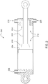
Figure 1 is a partial cutaway view of a hydraulic cylinder with an internal damper disposed at the cylinder end of the hydraulic cylinder. -
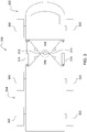
Figure 2 is a partial cutaway view of a hydraulic cylinder with an internal damper disposed at the rod end of the hydraulic cylinder. -
Figure 3 is a plan view of an articulated vehicle (a truck) using opposed hydraulic cylinders to steer the vehicle. -
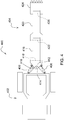
Figure 4 is a plan view of a backhoe using opposed hydraulic cylinders to swing the boom. -
Figures 5A-5B are schematic views of two embodiments for interconnecting and steering/swinging the hydraulic cylinders shown inFigures 3-4 in accordance with the present invention. - Referring to
Figure 1 , ahydraulic cylinder 100 comprises apiston rod 102, apiston 104 mounted on thepiston rod 102, arod end port 106 formed in the rod end of thehydraulic cylinder 100, acylinder end port 108 and a throttledcylinder end port 110 formed in the cylinder end of thehydraulic cylinder 100, and aninternal damper 112 that throttles hydraulic fluid flow through the throttledcylinder end port 110. - The
internal damper 112 comprises anaperture 114 formed in the cylinder end of thehydraulic cylinder 100, and arod 116 supported on the end of thepiston 104. - As the
piston 104 moves to the left inFigure 1 , hydraulic fluid flows out of thecylinder end port 108 and the throttledcylinder end port 110. Likewise, hydraulic fluid flows into therod end port 106. When thepiston 104 moves to the right inFigure 1 , the hydraulic fluid flows are reversed. - Eventually, as the piston moves to the left in
Figure 1 , therod 116 will be inserted into theaperture 114, and will begin to throttle hydraulic fluid flow out of the throttledcylinder end port 110. In the embodiment shown inFigure 1 , this throttling is gradual and a function of the piston position, since therod 116 has a tapered conical section that gradually blocks off theaperture 114 more and more as more and more of therod 116 is received in theaperture 114. Over substantially all the stroke of thehydraulic cylinder 100, theinternal damper 112 does not restrict the flow of hydraulic fluid out of thehydraulic cylinder 100. Only as thehydraulic cylinder 100 approaches the end of its working retraction stroke does theinternal damper 112 function. - The other ports on the
hydraulic cylinder 100 are not restricted and thus hydraulic fluid flow into and out of the other ports is not throttled. - Referring to
Figure 2 , ahydraulic cylinder 200 comprises apiston rod 202, apiston 204 mounted on thepiston rod 202, acylinder end port 206 formed in the cylinder end of thehydraulic cylinder 100, arod end port 208 and a throttledrod end port 210 formed in the rod end of thecylinder 100, and aninternal damper 212 that throttles hydraulic fluid flow through the throttledrod end port 210. - The
internal damper 212 comprises anannular aperture 214 formed in the rod end of thehydraulic cylinder 200, and atapered ring 216 disposed about the circumference of thepiston rod 202. - As the
piston 204 moves to the right inFigure 2 , hydraulic fluid flows out of therod end port 208 and the throttledrod end port 210. Likewise, hydraulic fluid flows into thecylinder end port 206. When thepiston 204 moves to the left inFigure 2 , the hydraulic fluid flows are reversed. - Eventually, as the piston moves to the right in
Figure 2 , thetapered ring 216 will be inserted into theannular aperture 214, and will begin to throttle hydraulic fluid flow out of the throttledrod end port 210. In the embodiment shown inFigure 1 , this throttling is gradual and a function of the piston position, since therod 216 has a tapered conical section that increasingly blocks off theannular aperture 214 as more and more of thetapered ring 216 is received in theannular aperture 214. - Over substantially all the stroke of the
hydraulic cylinder 200, theinternal damper 212 does not restrict the flow of hydraulic fluid out of thehydraulic cylinder 200. Only as thehydraulic cylinder 200 approaches the end of its working extension stroke does theinternal damper 212 function. - The other ports on the
hydraulic cylinder 200 are not restricted and thus flow into and out of the other ports is not throttled. - Referring to
Figure 3 , an articulatedtruck 300 comprises acabin portion 302 pivotally coupled to atrailer portion 304. Thecabin portion 302 and thetrailer portion 304 are supported onwheels 305 for travel over the ground. - A
first frame member 306 is formed integral with thecabin portion 302. Thesecond frame member 308 is formed integral with thetrailer portion 304. Thecabin portion 302 and thetrailer portion 304 are coupled together to form the articulated truck by apivot joint 310 formed by avertical pin 312 inserted into apertures in thefirst frame member 306 and thesecond frame member 308. - A first
hydraulic cylinder 314 is coupled at its rod end to the left side of thecabin portion 302, and is coupled at its cylinder end to the left side of thetrailer portion 304. A secondhydraulic cylinder 316 is coupled at its rod end to the right side of thecabin portion 302 and is coupled at its cylinder end to the right side of thetrailer portion 304. - In order to steer the articulated
truck 300 to the left, the firsthydraulic cylinder 314 is retracted, and the secondhydraulic cylinder 316 is extended. In order to steer the articulatedtruck 300 to the right, the firsthydraulic cylinder 314 is extended, and the secondhydraulic cylinder 316 is retracted. - Mechanical stops 318 on the
first frame member 306 and thesecond frame member 308 are provided to prevent oversteering to the left by abutting each other when the articulatedtruck 300 reaches its extreme leftmost steering position. Mechanical stops 320 on thefirst frame member 306 and thesecond frame member 308 are provided to prevent oversteering to the right by abutting each other when the articulatedtruck 300 reaches its extreme rightmost steering position. - The first
hydraulic cylinder 314 and the secondhydraulic cylinder 316 pivot thefirst frame member 306 and thesecond frame member 308 with respect to each other by moving in opposite directions, which means herein that the cylinders are coupled to the frame members such that one cylinder extends as the other cylinder simultaneously retracts in order to pivot the members in a first direction relative to each other, and one cylinder retracts as the other cylinder simultaneously extends to pivot the members in a second direction relative to each other that is opposite to the first direction. - Referring to
Figure 4 , abackhoe 400 comprises atractor 402 coupled to abackhoe attachment 404. A firsthydraulic cylinder 406 and a secondhydraulic cylinder 408 are coupled on either side of a pivot joint 410 to swing abackhoe boom base 412 to the left and to the right about avertical pivot pin 414 with respect to thetractor 402 in the same manner as described above regarding the articulatedtruck 300. Thebackhoe attachment 404 includes aboom base 412, to which one end of aboom 416 is pivotally coupled about ahorizontal pivot pin 418 to pivot up and down with respect to theboom base 412. Astick 420 is pivotally coupled at one end to the other end of theboom 416 about ahorizontal pivot pin 422 to pivot up and down with respect to theboom 416. Abucket 424 is pivotally coupled at one end to the other end of thestick 420 to pivot up and down with respect to thestick 420 about ahorizontal pivot pin 426. - In the arrangements of both
Figure 4 andFigure 5 , the relative pivoting movement between the frame members is limited. In other words, thecabin portion 302 cannot rotate freely with respect to thetrailer portion 304, nor can thebackhoe attachment 404 rotate freely with respect to thetractor 402. In both arrangements, the range of motion of one with respect to the other is limited. Typically, the range of relative movement (i.e. pivoting) is limited to 180° or less. Further relative movement is limited by the geometry of the hydraulic cylinders, mechanical stops, or other physical structures impeding the rotational movement. Since the range is limited in both directions, the relative movement has two limits: a first limit in one direction of pivoting, and a second limit in the other direction of pivoting. -
Figure 5A illustrates asystem 500 for steering the articulatedtruck 300 and swinging the boom of thebackhoe 400. Thesystem 500 comprises anoperator input device 502 which the operator manipulates to indicate his steering commands and communicate those commands to anECU 504. In response to the steering commands, theECU 504 controls ahydraulic valve 506 which selectively directs the flow of hydraulic fluid to a firsthydraulic cylinder 508 and to the secondhydraulic cylinder 510. Thehydraulic valve 506 is controlled by theECU 504 to selectively send hydraulic fluid to, and receive hydraulic fluid from, a first throttledcylinder end port 512 in the firsthydraulic cylinder 508 and a second throttledcylinder end port 514 in the secondhydraulic cylinder 510. - Ports on the first
hydraulic cylinder 508 and ports on the secondhydraulic cylinder 510 are directly coupled by a firsthydraulic line 516 and a secondhydraulic line 518. The firsthydraulic line 516 couples a non-throttled (or unrestricted)cylinder end port 520 of the firsthydraulic cylinder 508 to a non-throttled (or unrestricted)rod end port 522 of the secondhydraulic cylinder 510. The secondhydraulic line 518 couples a non-throttled (or unrestricted)cylinder end port 524 of the secondhydraulic cylinder 510 to a non-throttled (or unrestricted)rod end port 526 of the firsthydraulic cylinder 508. - The first
hydraulic cylinder 508 and the secondhydraulic cylinder 510 have the same construction and function the same as thehydraulic cylinder 100 ofFigure 1 . The system shown inFigure 5A can be used on the articulatedtruck 300 ofFigure 3 and on thebackhoe 400 ofFigure 4 . - When the system of
Figure 5A is used on the articulatedtruck 300 ofFigure 3 , the firsthydraulic cylinder 508 is equivalent to the firsthydraulic cylinder 314, and the secondhydraulic cylinder 510 is equivalent to the secondhydraulic cylinder 316. - When the system of
Figure 5A is used on thebackhoe 400 ofFigure 4 , the firsthydraulic cylinder 508 is equivalent to the firsthydraulic cylinder 406, and the secondhydraulic cylinder 510 is equivalent to the secondhydraulic cylinder 408. - The system of
Figure 5A operates as follows. When the operator signals swinging/steering to the left, theECU 504 moves the hydraulic valve toward valve position "A". This causes hydraulic fluid under pressure fromhydraulic pressure source 528 to fill the throttledcylinder end port 514 and the cylinder end of the secondhydraulic cylinder 510. The hydraulic fluid entering the cylinder end of the secondhydraulic cylinder 510 is also communicated through the cylinder end and out thecylinder end port 524 of the secondhydraulic cylinder 510 through the secondhydraulic line 518 and into therod end port 526 of the firsthydraulic cylinder 508. - This causes the first
hydraulic cylinder 508 to retract, and the secondhydraulic cylinder 510 to extend. - At the same time, hydraulic fluid in the rod end of the second
hydraulic cylinder 510 passes through therod end port 522, through the firsthydraulic conduit 516, and into thecylinder end port 520 of the firsthydraulic cylinder 508. It is received in the cylinder end of the firsthydraulic cylinder 508, and blows out of the throttledcylinder end port 512 of the firsthydraulic cylinder 508. It then passes through the hydraulic line connecting the firsthydraulic cylinder 508 to thevalve 506, passes through the valve, and returns to thehydraulic fluid reservoir 530. - Eventually, the first
hydraulic cylinder 508 retracts far enough that its internal damper 112 (seeFigure 1 ) restricts hydraulic fluid flow through the throttledcylinder end port 512. This causes the hydraulic fluid pressure in the cylinder end of the firsthydraulic cylinder 508 to increase substantially as a leftward movement of the cabin portion 302 (seeFigure 3 ) or the leftward movement of the backhoe attachment 404 (seeFigure 4 ) is damped. - The increased pressure in the cylinder end of the first
hydraulic cylinder 508 is communicated through the firsthydraulic line 516 to the rod end of the secondhydraulic cylinder 510. Thus, theinternal damper 112 of the firsthydraulic cylinder 508 simultaneously generates the same high pressure in the cylinder end of the firsthydraulic cylinder 508 and the rod end of the secondhydraulic cylinder 510. This common high pressure causes both cylinders to simultaneously apply equal decelerating forces to the vehicles to which they are attached. - Since the
cylinders valve 506 and their interconnections are symmetric, the operation described above regarding left turns is equally true regarding right turns. When the operator steers to the right, the internal damper in the secondhydraulic cylinder 510 will operate and the high pressure will be communicated between thecylinders hydraulic line 518. -
Figure 5B illustrates an alternative cylinder arrangement to the cylinder arrangement shown inFigure 5A . In theFigure 5B arrangement, hydraulic cylinder 200 (Figure 5B ) has been substituted for hydraulic cylinder 100 (Figure 5A ). TheFigure 5B arrangement functions the same as the arrangement ofFigure 5A . - The arrangement of
Figure 5B (shown in theFigure 5B dashed box) is substituted for the arrangement ofFigure 5A (shown in theFigure 5A dashed box). - The system of
Figure 5B operates as follows. When the operator signals swinging/steering to the right, theECU 504 moves the hydraulic valve toward valve position "A". This causes hydraulic fluid under pressure fromhydraulic pressure source 528 to fill the throttled rod end port 514' and the rod end of the second hydraulic cylinder 510'. The hydraulic fluid entering the rod end of the second hydraulic cylinder 510' is also communicated through the rod end and out the non-throttled (or unrestricted) cylinder end port 524' of the second hydraulic cylinder 510' through the second hydraulic line 518' and into the non-throttled (or unrestricted) cylinder end port 526' of the first hydraulic cylinder 508'. - This causes the first hydraulic cylinder 508' to extend, and the second hydraulic cylinder 510' to retract.
- At the same time, hydraulic fluid in the cylinder end of the second hydraulic cylinder 510' passes through the non-throttled (or unrestricted) cylinder end port 522', through the first hydraulic conduit 516', and into the non-throttled (or unrestricted) rod end port 520' of the first hydraulic cylinder 508'. It is received in the rod end of the first hydraulic cylinder 508', and flows out of the throttled rod end port 512' of the first hydraulic cylinder 508'. It then passes through the hydraulic line connecting the first hydraulic cylinder 508' to the
valve 506, passes through the valve, and returns to thehydraulic fluid reservoir 530. - Eventually, the first hydraulic cylinder 508' retracts far enough that its internal damper 212 (see
Figure 2 ) restricts hydraulic fluid flow through the throttled rod end port 512'. This causes the hydraulic fluid pressure in the rod end of the first hydraulic cylinder 508' to increase substantially as a rightward movement of the cabin portion 302 (seeFigure 3 ) or the leftward movement of the backhoe attachment 404 (seeFigure 4 ) is damped. - The increased pressure in the rod end of the first hydraulic cylinder 508' is communicated through the first hydraulic line 516' to the cylinder end of the second hydraulic cylinder 510'. Thus, the
internal damper 212 of the first hydraulic cylinder 508' simultaneously generates the same high pressure in the cylinder end of the first hydraulic cylinder 508' and the rod end of the second hydraulic cylinder 510'. This common high pressure causes both cylinders to simultaneously apply equal decelerating forces to the vehicles to which they are attached. - Since the cylinders 508', 510' are identical, and since their connections to the
valve 506 and their interconnections are symmetric, the operation described above regarding right turns is equally true regarding left turns. For example, when the operator steers to the left, theinternal damper 212 in the second hydraulic cylinder 510' will eventually operate and the high pressure generated by theinternal damper 212 will be communicated between the cylinders 508', 510' through the second hydraulic line 518'. - Considering the embodiments of
Figure 5A and ofFigure 5B together, both arrangements use an internal damper in one hydraulic cylinder to throttle hydraulic fluid flow leaving that cylinder and returning tovalve 506 as the steering/swinging reaches a limit defined by the dimensions and location of the internal damper. - As the hydraulic fluid flow is throttled, the increase in hydraulic fluid pressure is communicated through a cross conduit coupled between the rod end of one cylinder and the cylinder end of the other. The throttling prevents hydraulic fluid from flowing through this cross conduit, and thus (given that the two hydraulic cylinders have equal dimensions) generates an equal damping force in both cylinders that resists further swinging/steering. In both the embodiments of
Figure 5A inFigure 5B , the throttling reduces the flow of hydraulic fluid out of both cylinders. - The claims define the invention, which is not limited to the specific embodiment or embodiments described herein. Obvious variations of the specific embodiments shown herein will be apparent to one skilled in the art.
Claims (11)
- A work vehicle with a cylinder cushioning arrangement, comprising:a first vehicle frame member;a second vehicle frame member pivotally coupled to the first vehicle frame member at a pivot joint wherein the pivot joint defines an axis of pivot;a first hydraulic cylinder coupled to and between the first vehicle frame member and the second vehicle frame member, the first hydraulic cylinder having a unrestricted cylinder end port, an unrestricted rod end port, and either a restricted rod end port or a restricted cylinder end port;a second hydraulic cylinder coupled to and between the first vehicle frame member and the second vehicle frame member, the second hydraulic cylinder having an unrestricted cylinder end port, and unrestricted rod end port and either a restricted rod end port or a restricted cylinder end port;a first conduit hydraulically coupling the unrestricted rod end port of the first hydraulic cylinder to the unrestricted cylinder end port of the second hydraulic cylinder; anda second conduit hydraulically coupling the unrestricted cylinder end port of the first hydraulic cylinder to the unrestricted rod end port of the second hydraulic cylinder.
- The work vehicle of Claim 1, further comprising a hydraulic valve coupled to the restricted rod end port or the restricted cylinder end port of the first hydraulic cylinder, and also coupled to the restricted rod end port or the restricted cylinder end port of the second hydraulic cylinder, wherein the hydraulic valve is controllable to introduce hydraulic fluid into the first hydraulic cylinder and the second hydraulic cylinder, and to remove hydraulic fluid from the first hydraulic cylinder and the second hydraulic cylinder, to move the first hydraulic cylinder and the second hydraulic cylinder, and to thereby pivot the first vehicle frame member with respect to the second vehicle frame member.
- The work vehicle of Claim 2, wherein the first hydraulic cylinder further comprises a first internal damper that restricts flow through the restricted rod end port or the restricted cylinder end port of the first hydraulic cylinder; and wherein the second hydraulic cylinder further comprises a second internal damper that restricts flow through the restricted rod end port or the restricted cylinder end port of the second hydraulic cylinder.
- The work vehicle of Claim 3, wherein the first internal damper and the second internal damper are configured to respectively restrict flow of hydraulic fluid exiting the first hydraulic cylinder and the second hydraulic cylinder.
- The work vehicle of Claim 4. Wherein the first internal damper and the second internal damper are configured to not restrict flow of hydraulic fluid entering the first hydraulic cylinder and the second hydraulic cylinder, respectively.
- The work vehicle of Claim 3, wherein the first internal damper and the second internal damper are configured to limit an outflow of hydraulic fluid from the first hydraulic cylinder and the second hydraulic cylinder only near a limit of travel of the first hydraulic cylinder and the second hydraulic cylinder to thereby collectively cushion the first hydraulic cylinder and the second hydraulic cylinder at their limits of travel.
- The work vehicle of Claim 6, wherein the first internal damper cushions both the first hydraulic cylinder and the second hydraulic cylinder at a first limit of pivoting movement of the first vehicle frame member with respect to the second vehicle frame member in a first relative pivoting direction, and wherein the second internal damper cushions both the first hydraulic cylinder and the second hydraulic cylinder at a second limit of pivoting movement of the first vehicle frame member with respect to the second vehicle frame member in a second relative pivoting direction, wherein the second relative pivoting direction is a direction opposite to the first relative pivoting direction.
- The work vehicle of Claim 7, wherein the first internal damper of the first hydraulic cylinder cushions the second hydraulic cylinder by restricting hydraulic fluid flow out of one of the unrestricted cylinder end port, and the unrestricted rod end port.
- The work vehicle of Claim 3, wherein the first internal damper and the second internal damper comprise a rod extending from a piston and an aperture formed in a cylinder head of the first hydraulic cylinder, wherein the rod is received inside the aperture to restrict hydraulic fluid flow out of the restricted cylinder end port of the first hydraulic cylinder.
- The work vehicle of Claim 3, wherein the first internal damper of the first hydraulic cylinder comprises a tapered ring extending about a piston rod of the first hydraulic cylinder and an annular aperture formed in a rod end of the first hydraulic cylinder.
- The work vehicle of Claim 10 wherein the second internal damper of the second hydraulic cylinder comprises a tapered ring extending about a piston rod of the second hydraulic cylinder and an annular aperture formed in a rod end of the second hydraulic cylinder.
Applications Claiming Priority (1)
| Application Number | Priority Date | Filing Date | Title |
|---|---|---|---|
| US14/881,734 US9623717B1 (en) | 2015-10-13 | 2015-10-13 | Work vehicles with cylinder cushioning arrangement |
Publications (1)
| Publication Number | Publication Date |
|---|---|
| EP3156307A1 true EP3156307A1 (en) | 2017-04-19 |
Family
ID=57130238
Family Applications (1)
| Application Number | Title | Priority Date | Filing Date |
|---|---|---|---|
| EP16193342.9A Withdrawn EP3156307A1 (en) | 2015-10-13 | 2016-10-11 | Work vehicles with cylinder cushioning arrangement |
Country Status (2)
| Country | Link |
|---|---|
| US (1) | US9623717B1 (en) |
| EP (1) | EP3156307A1 (en) |
Cited By (2)
| Publication number | Priority date | Publication date | Assignee | Title |
|---|---|---|---|---|
| CN109203881A (en) * | 2018-08-10 | 2019-01-15 | 中冶宝钢技术服务有限公司 | Automobile-used pulls round mechanism |
| WO2021219246A1 (en) * | 2020-05-01 | 2021-11-04 | Caterpillar Sarl | Articulated truck steering |
Families Citing this family (1)
| Publication number | Priority date | Publication date | Assignee | Title |
|---|---|---|---|---|
| DE102021211490B4 (en) | 2021-10-12 | 2023-10-05 | Zf Friedrichshafen Ag | Motor vehicle vibration damper with a hydraulic end stop |
Citations (6)
| Publication number | Priority date | Publication date | Assignee | Title |
|---|---|---|---|---|
| US3238850A (en) * | 1962-10-13 | 1966-03-08 | Cie Parisienne Outil Air Compr | Jacks with damping means |
| GB1377726A (en) * | 1972-05-31 | 1974-12-18 | Volvo Bm | Arrangement for braking in the end position of a forwards-and- backwards movable body |
| JPS5993538A (en) * | 1982-11-19 | 1984-05-30 | Sumitomo Precision Prod Co Ltd | Cushion mechanism for hydraulic cylinder |
| FR2547872A1 (en) * | 1983-06-22 | 1984-12-28 | Poclain Sa | Fluid-type jack and circuit for actuating such a jack |
| US6382075B1 (en) * | 2000-07-05 | 2002-05-07 | Caterpillar S.A.R.L. | Snubbing arrangement for a fluid cylinder assembly |
| EP2657541A2 (en) * | 2012-04-24 | 2013-10-30 | Parker Hannifin Manufacturing Germany GmbH & Co. KG | Sealing assembly for a cylinder sealing assembly |
Family Cites Families (6)
| Publication number | Priority date | Publication date | Assignee | Title |
|---|---|---|---|---|
| US4386555A (en) * | 1979-02-09 | 1983-06-07 | Sperry Corporation | Hydraulic cylinder cushion device |
| US4381827A (en) * | 1979-02-23 | 1983-05-03 | General Motors Corporation | Steering mechanism for articulated vehicles |
| US4310061A (en) * | 1980-01-22 | 1982-01-12 | International Harvester Company | Steering geometry for articulated farm tractor |
| JPH0345471A (en) * | 1989-07-14 | 1991-02-27 | Komatsu Ltd | Handle position correction device for fully hydraulic steering system |
| CA2307926C (en) * | 2000-05-09 | 2002-06-11 | Degelman Industries Lp | Multi-functional self-propelled farm tractor |
| US7624836B2 (en) * | 2006-10-30 | 2009-12-01 | Caterpillar Inc. | Steering system having multiple strategies and variable deadzone |
-
2015
- 2015-10-13 US US14/881,734 patent/US9623717B1/en active Active
-
2016
- 2016-10-11 EP EP16193342.9A patent/EP3156307A1/en not_active Withdrawn
Patent Citations (6)
| Publication number | Priority date | Publication date | Assignee | Title |
|---|---|---|---|---|
| US3238850A (en) * | 1962-10-13 | 1966-03-08 | Cie Parisienne Outil Air Compr | Jacks with damping means |
| GB1377726A (en) * | 1972-05-31 | 1974-12-18 | Volvo Bm | Arrangement for braking in the end position of a forwards-and- backwards movable body |
| JPS5993538A (en) * | 1982-11-19 | 1984-05-30 | Sumitomo Precision Prod Co Ltd | Cushion mechanism for hydraulic cylinder |
| FR2547872A1 (en) * | 1983-06-22 | 1984-12-28 | Poclain Sa | Fluid-type jack and circuit for actuating such a jack |
| US6382075B1 (en) * | 2000-07-05 | 2002-05-07 | Caterpillar S.A.R.L. | Snubbing arrangement for a fluid cylinder assembly |
| EP2657541A2 (en) * | 2012-04-24 | 2013-10-30 | Parker Hannifin Manufacturing Germany GmbH & Co. KG | Sealing assembly for a cylinder sealing assembly |
Cited By (4)
| Publication number | Priority date | Publication date | Assignee | Title |
|---|---|---|---|---|
| CN109203881A (en) * | 2018-08-10 | 2019-01-15 | 中冶宝钢技术服务有限公司 | Automobile-used pulls round mechanism |
| CN109203881B (en) * | 2018-08-10 | 2022-02-11 | 中冶宝钢技术服务有限公司 | Traction steering mechanism for vehicle |
| WO2021219246A1 (en) * | 2020-05-01 | 2021-11-04 | Caterpillar Sarl | Articulated truck steering |
| US12221178B2 (en) | 2020-05-01 | 2025-02-11 | Caterpillar Sarl | Articulated truck steering |
Also Published As
| Publication number | Publication date |
|---|---|
| US20170100982A1 (en) | 2017-04-13 |
| US9623717B1 (en) | 2017-04-18 |
| BR102016022182A2 (en) | 2017-04-25 |
Similar Documents
| Publication | Publication Date | Title |
|---|---|---|
| DE60102143T2 (en) | HYDRAULIC SUSPENSION | |
| US9085857B2 (en) | Automotive milling machine, use of a lifting column of a milling machine, as well as method for increasing the operating efficiency of a milling machine | |
| AU2008251991B2 (en) | Spray linkage | |
| US7735838B2 (en) | Vehicle suspension with selectable roll stabilization | |
| US8201849B2 (en) | Agricultural vehicle balancing system | |
| US20090189407A1 (en) | Scissorless suspension system for a seat assembly and machine using same | |
| US9623717B1 (en) | Work vehicles with cylinder cushioning arrangement | |
| US20170164599A1 (en) | Spraying device and boom damping device | |
| US10343180B2 (en) | Control system, spray bar, carrier and method of implementation | |
| US9732500B2 (en) | Cushioned swing circuit | |
| JP5914389B2 (en) | Suspension device | |
| US6926113B2 (en) | Cushioned steering for articulated vehicle | |
| EP3259986A1 (en) | Boom arrangement and method for adjusting the tilt position of the boom arrangement | |
| AU2022201886A1 (en) | Hydraulic cylinder cushioning | |
| JP3852701B2 (en) | Hydraulic circuit using hydraulic cylinder | |
| US9340954B2 (en) | Regenerative circuit for articulated joint | |
| EP2952419B1 (en) | Spring damper element for the suspension of vehicle cabs | |
| EP1202869B1 (en) | Suspension system, especially cab suspension system | |
| RU2352475C1 (en) | Vehicle hydropneumatic suspension | |
| JP5914370B2 (en) | Wheeled work vehicle | |
| JP7820221B2 (en) | Boom spraying device and hydraulic cylinder for opening and closing the boom | |
| KR100261340B1 (en) | Rotary Reducing Hydraulic Valve | |
| CN213981784U (en) | Hydraulic shock absorber with supporting function | |
| RU2352474C1 (en) | Vehicle hydropneumatic suspension | |
| DE102016102854A1 (en) | Work vehicle with steerable articulated suspension joint damping and method for driving stabilization of the working vehicle |
Legal Events
| Date | Code | Title | Description |
|---|---|---|---|
| PUAI | Public reference made under article 153(3) epc to a published international application that has entered the european phase |
Free format text: ORIGINAL CODE: 0009012 |
|
| AK | Designated contracting states |
Kind code of ref document: A1 Designated state(s): AL AT BE BG CH CY CZ DE DK EE ES FI FR GB GR HR HU IE IS IT LI LT LU LV MC MK MT NL NO PL PT RO RS SE SI SK SM TR |
|
| AX | Request for extension of the european patent |
Extension state: BA ME |
|
| 17P | Request for examination filed |
Effective date: 20171019 |
|
| RBV | Designated contracting states (corrected) |
Designated state(s): AL AT BE BG CH CY CZ DE DK EE ES FI FR GB GR HR HU IE IS IT LI LT LU LV MC MK MT NL NO PL PT RO RS SE SI SK SM TR |
|
| 17Q | First examination report despatched |
Effective date: 20180306 |
|
| R17C | First examination report despatched (corrected) |
Effective date: 20180306 |
|
| STAA | Information on the status of an ep patent application or granted ep patent |
Free format text: STATUS: THE APPLICATION IS DEEMED TO BE WITHDRAWN |
|
| 18D | Application deemed to be withdrawn |
Effective date: 20181103 |