EP3156167B1 - Laser generator with a beam splitter, and excimer laser annealing device with such laser generator - Google Patents
Laser generator with a beam splitter, and excimer laser annealing device with such laser generator Download PDFInfo
- Publication number
- EP3156167B1 EP3156167B1 EP16784373.9A EP16784373A EP3156167B1 EP 3156167 B1 EP3156167 B1 EP 3156167B1 EP 16784373 A EP16784373 A EP 16784373A EP 3156167 B1 EP3156167 B1 EP 3156167B1
- Authority
- EP
- European Patent Office
- Prior art keywords
- laser beam
- laser
- energy
- region
- hole
- Prior art date
- Legal status (The legal status is an assumption and is not a legal conclusion. Google has not performed a legal analysis and makes no representation as to the accuracy of the status listed.)
- Active
Links
Images

Classifications
-
- G—PHYSICS
- G02—OPTICS
- G02B—OPTICAL ELEMENTS, SYSTEMS OR APPARATUS
- G02B27/00—Optical systems or apparatus not provided for by any of the groups G02B1/00 - G02B26/00, G02B30/00
- G02B27/10—Beam splitting or combining systems
- G02B27/14—Beam splitting or combining systems operating by reflection only
- G02B27/144—Beam splitting or combining systems operating by reflection only using partially transparent surfaces without spectral selectivity
-
- B—PERFORMING OPERATIONS; TRANSPORTING
- B23—MACHINE TOOLS; METAL-WORKING NOT OTHERWISE PROVIDED FOR
- B23K—SOLDERING OR UNSOLDERING; WELDING; CLADDING OR PLATING BY SOLDERING OR WELDING; CUTTING BY APPLYING HEAT LOCALLY, e.g. FLAME CUTTING; WORKING BY LASER BEAM
- B23K26/00—Working by laser beam, e.g. welding, cutting or boring
- B23K26/02—Positioning or observing the workpiece, e.g. with respect to the point of impact; Aligning, aiming or focusing the laser beam
- B23K26/06—Shaping the laser beam, e.g. by masks or multi-focusing
- B23K26/067—Dividing the beam into multiple beams, e.g. multi-focusing
-
- B—PERFORMING OPERATIONS; TRANSPORTING
- B23—MACHINE TOOLS; METAL-WORKING NOT OTHERWISE PROVIDED FOR
- B23K—SOLDERING OR UNSOLDERING; WELDING; CLADDING OR PLATING BY SOLDERING OR WELDING; CUTTING BY APPLYING HEAT LOCALLY, e.g. FLAME CUTTING; WORKING BY LASER BEAM
- B23K26/00—Working by laser beam, e.g. welding, cutting or boring
-
- G—PHYSICS
- G02—OPTICS
- G02B—OPTICAL ELEMENTS, SYSTEMS OR APPARATUS
- G02B27/00—Optical systems or apparatus not provided for by any of the groups G02B1/00 - G02B26/00, G02B30/00
- G02B27/09—Beam shaping, e.g. changing the cross-sectional area, not otherwise provided for
- G02B27/0905—Dividing and/or superposing multiple light beams
-
- G—PHYSICS
- G02—OPTICS
- G02B—OPTICAL ELEMENTS, SYSTEMS OR APPARATUS
- G02B27/00—Optical systems or apparatus not provided for by any of the groups G02B1/00 - G02B26/00, G02B30/00
- G02B27/09—Beam shaping, e.g. changing the cross-sectional area, not otherwise provided for
- G02B27/0938—Using specific optical elements
- G02B27/0988—Diaphragms, spatial filters, masks for removing or filtering a part of the beam
-
- G—PHYSICS
- G02—OPTICS
- G02B—OPTICAL ELEMENTS, SYSTEMS OR APPARATUS
- G02B27/00—Optical systems or apparatus not provided for by any of the groups G02B1/00 - G02B26/00, G02B30/00
- G02B27/10—Beam splitting or combining systems
- G02B27/106—Beam splitting or combining systems for splitting or combining a plurality of identical beams or images, e.g. image replication
-
- G—PHYSICS
- G02—OPTICS
- G02B—OPTICAL ELEMENTS, SYSTEMS OR APPARATUS
- G02B27/00—Optical systems or apparatus not provided for by any of the groups G02B1/00 - G02B26/00, G02B30/00
- G02B27/10—Beam splitting or combining systems
- G02B27/14—Beam splitting or combining systems operating by reflection only
- G02B27/143—Beam splitting or combining systems operating by reflection only using macroscopically faceted or segmented reflective surfaces
-
- G—PHYSICS
- G02—OPTICS
- G02B—OPTICAL ELEMENTS, SYSTEMS OR APPARATUS
- G02B5/00—Optical elements other than lenses
- G02B5/005—Diaphragms
-
- H—ELECTRICITY
- H01—ELECTRIC ELEMENTS
- H01S—DEVICES USING THE PROCESS OF LIGHT AMPLIFICATION BY STIMULATED EMISSION OF RADIATION [LASER] TO AMPLIFY OR GENERATE LIGHT; DEVICES USING STIMULATED EMISSION OF ELECTROMAGNETIC RADIATION IN WAVE RANGES OTHER THAN OPTICAL
- H01S3/00—Lasers, i.e. devices using stimulated emission of electromagnetic radiation in the infrared, visible or ultraviolet wave range
- H01S3/005—Optical devices external to the laser cavity, specially adapted for lasers, e.g. for homogenisation of the beam or for manipulating laser pulses, e.g. pulse shaping
- H01S3/0071—Beam steering, e.g. whereby a mirror outside the cavity is present to change the beam direction
-
- H—ELECTRICITY
- H01—ELECTRIC ELEMENTS
- H01S—DEVICES USING THE PROCESS OF LIGHT AMPLIFICATION BY STIMULATED EMISSION OF RADIATION [LASER] TO AMPLIFY OR GENERATE LIGHT; DEVICES USING STIMULATED EMISSION OF ELECTROMAGNETIC RADIATION IN WAVE RANGES OTHER THAN OPTICAL
- H01S3/00—Lasers, i.e. devices using stimulated emission of electromagnetic radiation in the infrared, visible or ultraviolet wave range
- H01S3/14—Lasers, i.e. devices using stimulated emission of electromagnetic radiation in the infrared, visible or ultraviolet wave range characterised by the material used as the active medium
- H01S3/22—Gases
- H01S3/223—Gases the active gas being polyatomic, i.e. containing two or more atoms
- H01S3/225—Gases the active gas being polyatomic, i.e. containing two or more atoms comprising an excimer or exciplex
Definitions
- the present invention relates to field of display technology, and particularly to a laser generator and an excimer laser annealing apparatus.
- a laser generator may specifically include a laser tube 01, a beam splitter 02, a reflective sheet 03 and an energy monitoring unit 04.
- a mixed gas consisted of xenon gas, neon gas, helium gas is discharged at a high voltage to generate photon, forming a laser beam.
- the laser beam is transmitted from the laser tube 01 to the beam splitter 02 and is converted into two laser beams after passing through the beam splitter 02.
- the beam splitter 02 is a high-transmission sheet, which has, for example, a transmission of 98% and a reflectivity of 2%.
- 98% of the laser beam transmits through the beam splitter 02 and then is formed as a linear optical source after undergoing a serious of optical transformations.
- the formed linear optical source can perform a scanning annealing on amorphous silicon.
- 2% of the laser beam is reflected to the reflective sheet 03 and finally arrives at the energy monitoring unit 04.
- the energy monitoring unit 04 can use the 2% of the laser beam as feedback parameter to generate a feedback control signal, so that operator may timely adjust the energy of the laser beam that is generated by the laser tube 01 according to the feedback control signal.
- the beam splitter 02 may be polluted and in turn the transmission of the beam splitter 02 is degraded, which causes energy of the transmitted laser beam to be reduced so that a difference between the energy of the transmitted laser beam and that of the laser beam generated by the laser tube 01 is formed. Further, due to the polluted beam splitter 02, the homogeneity of the transmitted laser beam is degraded.
- CN103557847 discloses a beam splitter including an incident face.
- a transmitted region is provided in a center in the incident face and four reflective faces are provided around a central through hole in the center of the beam splitter.
- the four reflective faces may reflect the laser beam to four directions. It is thus advantage that the beam splitter may provide five laser beams by using a single laser beam.
- US 5,161,238 discloses an apparatus for confining or limiting laser beams of medium and high power.
- the apparatus comprises a diaphragm which is mirrored and is arranged with respect to the laser beam in such a manner that the beam portions reflected by the diaphragm are directed away from the laser beam axis.
- JP 2002/314175 discloses a laser resonator unit having apertures for determining the mode order of the laser beam.
- US 3,578,849 (basis for the preamble of claim 1) discloses a diaphragm for a laser amplifier chain, comprising an element operable as a transparent divergent lens to an incident laser beam and including an aperture disposed centrally of the lens and of a size to permit a substantial part of a laser beam to pass from a driver laser to a laser amplifier.
- the element has a planar face on the side of the driver laser and a concave recess surrounding the aperture on its other side.
- Embodiments of the present invention provide a laser generator and an excimer laser annealing apparatus, which can reduce probability of pollution of the beam splitter to some extent and increase homogeneity of the laser beam that is passed through the beam splitter.
- the present invention provides a laser generator as listed in claim 1, comprising:
- the first laser beam (101) comprises a first region (21) where an energy of the first laser beam (101) is centralized and a second region (22) where an energy of the first laser beam (101) is diffused; a projection of the through-hole (12) along a transmission direction of the first laser beam (101) is located within a projection of the first region (21) along a transmission direction of the first laser beam (101).
- the projection of the through-hole (12) along the transmission direction of the first laser beam is fully overlapped with the projection of the first region (21) along the transmission direction of the first laser beam.
- a cross section of the through-hole (12) transverse to a transmission direction of the first laser beam is in a rectangle shape.
- the reflective region (11) is provided with a high-reflection mirror.
- the high-reflection mirror includes a reflective substrate and a reflective film that is coated on the reflective substrate.
- embodiments of the present invention provide an excimer laser annealing apparatus comprising the laser generator as described in any of the above, see claim 7.
- Embodiments of the present invention provide a laser generator and an excimer laser annealing apparatus.
- the beam splitter includes the transmission region and the reflective region.
- the transmission region is the through-hole and the reflective region is arranged at a periphery of the through-hole, wherein the through-hole is configured to be transmitted by the first laser beam that is received; and the reflective region is configured to reflect the first laser beam that is received.
- a portion of the first laser beam that is passed through the through-hole of the beam splitter can directly transmit through the beam splitter, instead of passing through a high-transmission sheet like that in prior art, to form the second laser beam, thereby avoiding attenuation of the energy of the laser beam caused by passing the laser beam through the high-transmission sheet and degradation of homogeneity of the second laser beam caused by passing the second laser beam through the polluted high-transmission sheet, which reduces probability of pollution of the beam splitter to some extent and increases homogeneity of the laser beam that passes through the beam splitter.
- a beam splitter 100 comprises a transmission region and a reflective region 11.
- the transmission region is configured as a through-hole 12 and the reflective region 11 is arranged at a periphery of the through-hole 12.
- the transmission region is configured to be transmitted by a first laser beam 101 that is received to form a second laser beam 102; the reflective region 11 is configured to reflect the first laser beam 101 that is received to form a third laser beam 103.
- the first laser beam 101 transmits directly through the beam splitter 100 via the through-hole 12 of the beam splitter 100 to form the second laser beam 102, without passing through a high-transmission sheet like that in prior art, thereby avoiding attenuation of the energy of the laser beam caused by passing the laser beam through the high-transmission sheet and degradation of homogeneity of the second laser beam caused by passing the laser beam through the polluted high-transmission sheet.
- the second laser beam 102 that is transmitted through the beam splitter 100 after being performed a series of optical transformation, can be used as a linear light source to perform a scanning annealing process on amorphous silicon. Due to good homogeneity of the second laser beam 102, an improved effect of the scanning annealing process can be achieved.
- the reflective region 11 arranged at the periphery of the through-hole 12 can reflect a portion of the first laser beam 101 to form the third laser beam 103, it ensures the third laser beam 103 may be considered as a feedback variable of the laser generator subsequently to generate a feedback control signal such that operator may timely adjust the energy of the first laser beam 101 that is generated by the laser generator according to the feedback control signal.
- the first laser beam 101 generated by the laser tube within the laser generator includes a first region 21 where an energy of the first laser beam is centralized and a second region 22 where an energy of the first laser beam is diffused.
- the energy in central region of the first laser beam 101 is relatively centralized and the homogeneity is relatively good while energy in periphery region of the first laser beam 101 is gradually diffused.
- a projection of the through-hole 12 along a transmission direction of the first laser beam 101 is located within a projection of the first region 21 along a transmission direction of the first laser beam 101. In this way, the homogeneity of the second laser beam 102 that is transmitted through the through-hole 12 is relatively better.
- the projection of the through-hole 12 along the transmission direction of the first laser beam 101 is fully overlapped with the projection of the first region 21 along the transmission direction of the first laser beam 101.
- the first laser beam 101 generated by the laser tube within the laser generator has a rectangle cross section.
- the first laser beam 101 has a cross section in a size of 12mm ⁇ 36mm.
- the through-hole 12 may be configured to have a rectangle cross section.
- the projection of the through-hole 12 having a rectangle cross section along the transmission direction of the first laser beam 101 is fully overlapped with the projection of the first region 21 along the transmission direction of the first laser beam 101.
- the second laser beam 102 transmitted from the rectangle through-hole 12 is a portion of the first laser beam 101 of which energy is centralized and maximized.
- the second laser beam 102 that is transmitted is in good homogeneity and has high energy.
- the obtained second laser beam 102 is not affected, thereby avoiding increment in amount of attenuation and degradation of the homogeneity of the second laser beam 102 resulting from passing the laser beam through the high-transmission sheet and the like.
- the reflective region 11 provided at the periphery of the through-hole 12 may be specifically a high-reflectivity mirror.
- the high-reflectivity mirror may include a reflective substrate and a reflective film that is coated on the reflective substrate.
- the reflective film can increase reflectivity of the high-reflectivity mirror and thus reduce amount of attenuation when forming the third laser beam 103.
- the present invention provides a laser generator 200 comprising the above-mentioned beam splitter 100.
- the laser generator 200 includes a laser tube 31, a beam splitter 100, a reflective sheet 32 and an energy monitoring unit 33.
- the laser tube 31 is configured to generate a first laser beam 101 and the first laser beam 101 is transmitted to the beam splitter 100.
- a mixed gas consisted of xenon gas, neon gas, helium gas is discharged at a high voltage to generate photon, forming a first laser beam 101.
- the first laser beam 101 is transmitted from the laser tube 31 to the beam splitter 100.
- the beam splitter 100 is configured to receive the first laser beam 101 generated by the laser tube 31, and, by referring a structural schematic view of the beam splitter 100 as shown in Figure 3 , a portion of the first laser beam 101 that is passed through the through-hole 12 of the beam splitter 100 is transmitted to form the second laser beam 102 and a portion of the first laser beam 101 is reflected by the reflective region 11 of the beam splitter 100 to form the third laser beam 103.
- the reflective sheet 32 is configured to change a transmission direction of the portion of the third laser beam 103 that is formed by the beam splitter 100 such that the third laser beam 103 is transmitted to the energy monitoring unit 33.
- the number of the reflective sheet 32 may be greater than one.
- the energy monitoring unit 33 is configured to detect an energy of the third laser beam 103 and to generate a feedback control signal according to the energy of the third laser beam such that operator can timely adjust the energy of the first laser beam generated in the laser tube 31 according to the feedback control signal.
- the energy of the first laser beam 101 formed by the laser tube 31 is W1
- the energy of the second laser beam 102 formed by the portion of the first laser beam 101 that is passed through the beam splitter 100 is W2
- the energy of the third laser beam 103 formed by the portion of the first laser beam 101 is W3.
- the operator can perform an adjustment of the laser generator when W3 which is monitored by the energy monitoring unit 33 is decreased, so as to increase the energy W2 of the second laser beam102 to as the same level as it is before being polluted, thereby ensuring the second laser beam 102 to output a stable energy in subsequent processes.
- the beam splitter 100 is composed of the through-hole 12 and the reflective region 11 arranged at the periphery of the through-hole 12.
- the first laser beam 101 formed by the laser tube 31 is irradiated to the through-hole 12
- a portion of the first laser beam 101 in a size equal to the through-hole 12 may be transmitted directly by the through-hole 12 to form the second laser beam 102.
- the energy W2 of the second laser beam 102 will not change as a result from pollution of the beam splitter 100, probability of change of energy difference between the energy W2 of the second laser beam 102 and the energy W1 of the first laser beam 101 may be reduced. Meanwhile, the homogeneity of the second laser beam 102 will not degrade as a result from pollution of the beam splitter 100.
- the first laser beam 101 generated in the laser tube 31 of the laser generator 200 is generally rectangle and the first laser beam 101 includes the first region 21 where energy of the first laser beam is centralized and the second region 22 where energy of the first laser beam is diffused, energy of the portion in the center location of the first laser beam 101 is centralized and homogeneity of the portion is relatively better while the portion in peripheral location of the first laser beam 101 is diffused gradually.
- the through-hole 12 may be configured to have a rectangle cross section and the projection of the through-hole 12 along the transmission direction of the first laser beam 101 is fully overlapped with the projection of the first region 21 along the transmission direction of the first laser beam 101.
- a recipe is needed to be set.
- the recipe may be set as W set .
- the operator input the energy W2 of the second laser beam 102 to a calibration window as the energy W1' (i.e., energy displayed within the tube) of the first laser beam 101 that does not pass through the beam splitter 100 and is calibrated.
- the value of n is not changed for a while after calibration, adjustment of the recipe W set naturally results in change of W3, and in turn, the change of W3 necessarily results in a change of the energy W1 of the first laser beam 101 generated by the laser tube 31.
- the energy W2 of the second laser beam 102 that is passed through the through-hole will not change as a result from pollution of the beam splitter 100
- the energy W2 of the second laser beam 102 is relatively stable and probability of change of energy difference between the energy W2 of the second laser beam 102 and the energy W1 of the first laser beam 101 may be reduced.
- the time of calibration performed by the operator according to the energy W3 of the third laser beam 103 as the feedback control signal may be reduced while avoiding pollution and obtaining the second laser beam with a relative homogenous energy.
- embodiments of the present invention provide an excimer laser annealing apparatus (ELA) comprising the above laser generator 200.
- ELA excimer laser annealing apparatus
- the laser generator 200 of the excimer laser annealing apparatus generates the second laser beam 102, and the second laser beam 102 may be used as a linear light source after being performed a series of subsequent optical transformations. For example, it is used to perform a scanning annealing process on amorphous silicon.
- the laser beam may directly pass through the through-hole 12 of the beam splitter 100, instead of passing through a high-transmission sheet like that in prior art, to form the second laser beam 102, the second laser beam 102 obtained has a good homogeneity and is favor of annealing effect of the subsequent scanning annealing process.
- Embodiments of the present invention provide a laser generator and an excimer laser annealing apparatus.
- the beam splitter includes the transmission region and the reflective region.
- the transmission region is the through-hole and the reflective region is arranged at a periphery of the through-hole, wherein the through-hole is configured to be transmitted by the first laser beam that is received; and the reflective region is configured to reflect the first laser beam that is received.
- a portion of the first laser beam that is passed through the through-hole of the beam splitter can directly transmit through the beam splitter, instead of passing through a high-transmission sheet like that in prior art, to form the second laser beam, thereby avoiding attenuation of the energy of the laser beam caused by passing the laser beam through the high-transmission sheet and degradation of homogeneity of the second laser beam caused by passing the second laser beam through the polluted high-transmission sheet, which reduces probability of pollution of the beam splitter to the extent and increases homogeneity of the laser beam that passes through the beam splitter.
Landscapes
- Physics & Mathematics (AREA)
- Optics & Photonics (AREA)
- Engineering & Computer Science (AREA)
- General Physics & Mathematics (AREA)
- Plasma & Fusion (AREA)
- Electromagnetism (AREA)
- Mechanical Engineering (AREA)
- Spectroscopy & Molecular Physics (AREA)
- Lasers (AREA)
- Recrystallisation Techniques (AREA)
Description
- The present invention relates to field of display technology, and particularly to a laser generator and an excimer laser annealing apparatus.
- Currently, as shown in
Figure 1 , a laser generator may specifically include alaser tube 01, abeam splitter 02, areflective sheet 03 and anenergy monitoring unit 04. Specifically, within thelaser tube 01, a mixed gas consisted of xenon gas, neon gas, helium gas is discharged at a high voltage to generate photon, forming a laser beam. The laser beam is transmitted from thelaser tube 01 to thebeam splitter 02 and is converted into two laser beams after passing through thebeam splitter 02. - Generally, as shown in
Figure 2 , thebeam splitter 02 is a high-transmission sheet, which has, for example, a transmission of 98% and a reflectivity of 2%. In this way, 98% of the laser beam transmits through thebeam splitter 02 and then is formed as a linear optical source after undergoing a serious of optical transformations. The formed linear optical source can perform a scanning annealing on amorphous silicon. 2% of the laser beam is reflected to thereflective sheet 03 and finally arrives at theenergy monitoring unit 04. Theenergy monitoring unit 04 can use the 2% of the laser beam as feedback parameter to generate a feedback control signal, so that operator may timely adjust the energy of the laser beam that is generated by thelaser tube 01 according to the feedback control signal. - After usage for a period of time, the
beam splitter 02 may be polluted and in turn the transmission of thebeam splitter 02 is degraded, which causes energy of the transmitted laser beam to be reduced so that a difference between the energy of the transmitted laser beam and that of the laser beam generated by thelaser tube 01 is formed. Further, due to the pollutedbeam splitter 02, the homogeneity of the transmitted laser beam is degraded. - In the prior art,
CN103557847 discloses a beam splitter including an incident face. A transmitted region is provided in a center in the incident face and four reflective faces are provided around a central through hole in the center of the beam splitter. The four reflective faces may reflect the laser beam to four directions. It is thus advantage that the beam splitter may provide five laser beams by using a single laser beam. -
US 5,161,238 discloses an apparatus for confining or limiting laser beams of medium and high power. The apparatus comprises a diaphragm which is mirrored and is arranged with respect to the laser beam in such a manner that the beam portions reflected by the diaphragm are directed away from the laser beam axis. -
JP 2002/314175 -
US 3,578,849 (basis for the preamble of claim 1) discloses a diaphragm for a laser amplifier chain, comprising an element operable as a transparent divergent lens to an incident laser beam and including an aperture disposed centrally of the lens and of a size to permit a substantial part of a laser beam to pass from a driver laser to a laser amplifier. The element has a planar face on the side of the driver laser and a concave recess surrounding the aperture on its other side. - Embodiments of the present invention provide a laser generator and an excimer laser annealing apparatus, which can reduce probability of pollution of the beam splitter to some extent and increase homogeneity of the laser beam that is passed through the beam splitter.
- The present invention provides a laser generator as listed in claim 1, comprising:
- a laser tube (31) configured to generate a first laser beam (101); a beam splitter (100) configured to receive the first laser beam (101);
wherein the beam splitter (100) comprises a transmission region configured as a through-hole (12),
wherein the through-hole (12) is configured to allow transmission of a first laser beam (101) that is received; and - wherein the first laser beam is transmitted by the through-hole (12) of the beam splitter to form a second laser beam (102),
- characterized in that:
- the beam splitter (100) further comprises a reflective region (11) arranged at a periphery of the through-hole (12), and the reflective region (11) is configured to reflect the first laser beam (101) that is received;
- the laser generator further comprises:
- a reflective sheet (32) and an energy monitoring unit (33), wherein the first laser beam (101) that is received is reflected by the reflective region of the beam splitter (100) to form a third laser beam (103);
- the reflective sheet (32) is configured to change a direction in which the third laser beam (103) is transmitted such that the third laser beam (103) is transmitted to the energy monitoring unit (33); and
- the energy monitoring unit (33) is configured to detect an energy of the third laser beam (103) and generate a feedback control signal according to the energy of the third laser beam (103), such that an operator can timely adjust the energy of the first laser beam (101) generated in the laser tube (31) according to the feedback control signal.
- In an embodiment, the first laser beam (101) comprises a first region (21) where an energy of the first laser beam (101) is centralized and a second region (22) where an energy of the first laser beam (101) is diffused;
a projection of the through-hole (12) along a transmission direction of the first laser beam (101) is located within a projection of the first region (21) along a transmission direction of the first laser beam (101). - In an embodiment, the projection of the through-hole (12) along the transmission direction of the first laser beam is fully overlapped with the projection of the first region (21) along the transmission direction of the first laser beam.
- In an embodiment, a cross section of the through-hole (12) transverse to a transmission direction of the first laser beam is in a rectangle shape.
- In an embodiment, the reflective region (11) is provided with a high-reflection mirror.
- In an embodiment, the high-reflection mirror includes a reflective substrate and a reflective film that is coated on the reflective substrate.
- In another aspect, embodiments of the present invention provide an excimer laser annealing apparatus comprising the laser generator as described in any of the above, see claim 7.
- Embodiments of the present invention provide a laser generator and an excimer laser annealing apparatus. The beam splitter includes the transmission region and the reflective region. Specifically, the transmission region is the through-hole and the reflective region is arranged at a periphery of the through-hole, wherein the through-hole is configured to be transmitted by the first laser beam that is received; and the reflective region is configured to reflect the first laser beam that is received. As a result, a portion of the first laser beam that is passed through the through-hole of the beam splitter can directly transmit through the beam splitter, instead of passing through a high-transmission sheet like that in prior art, to form the second laser beam, thereby avoiding attenuation of the energy of the laser beam caused by passing the laser beam through the high-transmission sheet and degradation of homogeneity of the second laser beam caused by passing the second laser beam through the polluted high-transmission sheet, which reduces probability of pollution of the beam splitter to some extent and increases homogeneity of the laser beam that passes through the beam splitter.
- In order to more clearly indicate the technical schemes in embodiments of the present invention or in prior art, the drawings that are used to illustrate the embodiments or the prior art will be described simply hereafter. Obviously, the drawings in the followings belong to merely some embodiments of the present invention. However, it is obvious for those skilled in the art to obtain other drawings based on the disclosed drawings without involving inventive labor.
-
Figure 1 is a schematic structural view of a laser generator in prior art; -
Figure 2 is a schematic structural view of a beam splitter in prior art; -
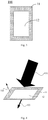
Figure 3 is a first schematic structural view of a beam splitter; -
Figure 4 is a first schematic principle view of a beam splitter; -
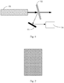
Figure 5 is a schematic structural view for providing a first laser beam; -
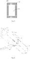
Figure 6 is a second schematic principle view of a beam splitter; and -
Figure 7 is a structural schematic view of a laser generator according to an embodiment of the present invention. - In the following description, in order to illustrate rather than limit, there are provided specific details regarding, such as, system structure, interface and technology, etc., so that the present invention is completely understood. However, it is appreciated by those skilled in the art that the present invention can be achieved in other embodiments without these details. In other situation, the description about details of well-known device, electric circuit and approach is omitted for facilitating the description of the present invention without unnecessary details.
- In addition, terms of "first", "second" are only used for description, and should not be understood to hint or suggest "priority" or to impliedly represent the number of the involved features. As such, the feature defined by wordings of "first", "second" may obviously or impliedly include one or more such feature(s). In the description of the present invention, wordings of "a plurality of' mean two or more, unless otherwise specified.
- As shown in
Figure 3 , abeam splitter 100 comprises a transmission region and areflective region 11. Specifically, the transmission region is configured as a through-hole 12 and thereflective region 11 is arranged at a periphery of the through-hole 12. - Specifically, as shown in
Figure 4 , the transmission region is configured to be transmitted by afirst laser beam 101 that is received to form asecond laser beam 102; thereflective region 11 is configured to reflect thefirst laser beam 101 that is received to form athird laser beam 103. - In this way, a portion of the
first laser beam 101 transmits directly through thebeam splitter 100 via the through-hole 12 of thebeam splitter 100 to form thesecond laser beam 102, without passing through a high-transmission sheet like that in prior art, thereby avoiding attenuation of the energy of the laser beam caused by passing the laser beam through the high-transmission sheet and degradation of homogeneity of the second laser beam caused by passing the laser beam through the polluted high-transmission sheet. Thesecond laser beam 102 that is transmitted through thebeam splitter 100, after being performed a series of optical transformation, can be used as a linear light source to perform a scanning annealing process on amorphous silicon. Due to good homogeneity of thesecond laser beam 102, an improved effect of the scanning annealing process can be achieved. - Meanwhile, since the
reflective region 11 arranged at the periphery of the through-hole 12 can reflect a portion of thefirst laser beam 101 to form thethird laser beam 103, it ensures thethird laser beam 103 may be considered as a feedback variable of the laser generator subsequently to generate a feedback control signal such that operator may timely adjust the energy of thefirst laser beam 101 that is generated by the laser generator according to the feedback control signal. - Specifically, as shown in
Figure 5 , thefirst laser beam 101 generated by the laser tube within the laser generator includes afirst region 21 where an energy of the first laser beam is centralized and asecond region 22 where an energy of the first laser beam is diffused. Generally, the energy in central region of thefirst laser beam 101 is relatively centralized and the homogeneity is relatively good while energy in periphery region of thefirst laser beam 101 is gradually diffused. - Thus, in order to improve homogeneity of the
second laser beam 102, as shown inFigure 6 , a projection of the through-hole 12 along a transmission direction of thefirst laser beam 101 is located within a projection of thefirst region 21 along a transmission direction of thefirst laser beam 101. In this way, the homogeneity of thesecond laser beam 102 that is transmitted through the through-hole 12 is relatively better. - Further, in order to obtain the
second laser beam 102 with a good homogeneity to a maximum extent, still as shown inFigure 6 , the projection of the through-hole 12 along the transmission direction of thefirst laser beam 101 is fully overlapped with the projection of thefirst region 21 along the transmission direction of thefirst laser beam 101. - Further, the
first laser beam 101 generated by the laser tube within the laser generator has a rectangle cross section. For example, thefirst laser beam 101 has a cross section in a size of 12mm×36mm. Thus, the through-hole 12 may be configured to have a rectangle cross section. Further, the projection of the through-hole 12 having a rectangle cross section along the transmission direction of thefirst laser beam 101 is fully overlapped with the projection of thefirst region 21 along the transmission direction of thefirst laser beam 101. - With this configuration, the
second laser beam 102 transmitted from the rectangle through-hole 12 is a portion of thefirst laser beam 101 of which energy is centralized and maximized. Thus, thesecond laser beam 102 that is transmitted is in good homogeneity and has high energy. - Further, since the
first laser beam 101 may directly transmit through the rectangle through-hole 12 without passing through the high-transmission sheet that may be polluted, the obtainedsecond laser beam 102 is not affected, thereby avoiding increment in amount of attenuation and degradation of the homogeneity of thesecond laser beam 102 resulting from passing the laser beam through the high-transmission sheet and the like. - In addition, the
reflective region 11 provided at the periphery of the through-hole 12 may be specifically a high-reflectivity mirror. - In an embodiment, specifically, the high-reflectivity mirror may include a reflective substrate and a reflective film that is coated on the reflective substrate. The reflective film can increase reflectivity of the high-reflectivity mirror and thus reduce amount of attenuation when forming the
third laser beam 103. - The present invention provides a
laser generator 200 comprising the above-mentionedbeam splitter 100. As an example, as shown inFigure 7 , thelaser generator 200 includes alaser tube 31, abeam splitter 100, areflective sheet 32 and anenergy monitoring unit 33. - According to the present invention, the
laser tube 31 is configured to generate afirst laser beam 101 and thefirst laser beam 101 is transmitted to thebeam splitter 100. Specifically, within thelaser tube 31, a mixed gas consisted of xenon gas, neon gas, helium gas is discharged at a high voltage to generate photon, forming afirst laser beam 101. Thefirst laser beam 101 is transmitted from thelaser tube 31 to thebeam splitter 100. - The
beam splitter 100 is configured to receive thefirst laser beam 101 generated by thelaser tube 31, and, by referring a structural schematic view of thebeam splitter 100 as shown inFigure 3 , a portion of thefirst laser beam 101 that is passed through the through-hole 12 of thebeam splitter 100 is transmitted to form thesecond laser beam 102 and a portion of thefirst laser beam 101 is reflected by thereflective region 11 of thebeam splitter 100 to form thethird laser beam 103. - The
reflective sheet 32 is configured to change a transmission direction of the portion of thethird laser beam 103 that is formed by thebeam splitter 100 such that thethird laser beam 103 is transmitted to theenergy monitoring unit 33. The number of thereflective sheet 32 may be greater than one. - The
energy monitoring unit 33 is configured to detect an energy of thethird laser beam 103 and to generate a feedback control signal according to the energy of the third laser beam such that operator can timely adjust the energy of the first laser beam generated in thelaser tube 31 according to the feedback control signal. - It is assumed that the energy of the
first laser beam 101 formed by thelaser tube 31 is W1, the energy of thesecond laser beam 102 formed by the portion of thefirst laser beam 101 that is passed through thebeam splitter 100 is W2 and the energy of thethird laser beam 103 formed by the portion of thefirst laser beam 101 is W3. - Then, W2=W1×a transmission of the
beam splitter 100;
W3=W1×a reflectivity of thebeam splitter 100.
wherein, if the transmission of the high-transmission sheet is 98%, its reflectivity is 2%. In this situation, after the laser generator is used for a period of time, the high-transmission sheet will be polluted, resulting in decrements of the transmission and the reflectivity of the high-transmission sheet, that is, resulting in decrements of W2 and W3. As theenergy monitoring unit 33 can monitor the energy W3 of thethird laser beam 103 and generate the feedback control signal, the operator can perform an adjustment of the laser generator when W3 which is monitored by theenergy monitoring unit 33 is decreased, so as to increase the energy W2 of the second laser beam102 to as the same level as it is before being polluted, thereby ensuring thesecond laser beam 102 to output a stable energy in subsequent processes. - From the above formula, it is needed to increase the energy W1 of the
first laser beam 101 formed by thelaser tube 31 so that the energy W2 of thesecond laser beam 102 will be increased to be equal to the energy value of thesecond laser beam 102 before being polluted. As a result, the energy W1 of thefirst laser beam 101 will become greater. - As a result, not only the energy difference between the inside and the outside of the high-transmission sheet becomes greater so that the high-transmission sheet will be blown out because of absorbing too much energy, but also the homogeneity of the
second laser beam 102 formed by the portion of the first laser beam that is passed through the high-transmission sheet will become worse and worse with the increasing pollution of the high-transmission sheet, which will seriously affect quality of the subsequent processes. - By comparison, in the
laser generator 200 according to the present invention, thebeam splitter 100 is composed of the through-hole 12 and thereflective region 11 arranged at the periphery of the through-hole 12. When thefirst laser beam 101 formed by thelaser tube 31 is irradiated to the through-hole 12, a portion of thefirst laser beam 101 in a size equal to the through-hole 12 may be transmitted directly by the through-hole 12 to form thesecond laser beam 102. In the above process, since the energy W2 of thesecond laser beam 102 will not change as a result from pollution of thebeam splitter 100, probability of change of energy difference between the energy W2 of thesecond laser beam 102 and the energy W1 of thefirst laser beam 101 may be reduced. Meanwhile, the homogeneity of thesecond laser beam 102 will not degrade as a result from pollution of thebeam splitter 100. - Alternatively, as a cross section of the
first laser beam 101 generated in thelaser tube 31 of thelaser generator 200 is generally rectangle and thefirst laser beam 101 includes thefirst region 21 where energy of the first laser beam is centralized and thesecond region 22 where energy of the first laser beam is diffused, energy of the portion in the center location of thefirst laser beam 101 is centralized and homogeneity of the portion is relatively better while the portion in peripheral location of thefirst laser beam 101 is diffused gradually. - Thus, in order to further increase homogeneity of the
second laser beam 102, the through-hole 12 may be configured to have a rectangle cross section and the projection of the through-hole 12 along the transmission direction of thefirst laser beam 101 is fully overlapped with the projection of thefirst region 21 along the transmission direction of thefirst laser beam 101. - As an example, when adjustment or calibration is performed in practice, a recipe is needed to be set. The recipe may be set as Wset. In this situation, when the energy W2 of the
second laser beam 102 decreases over time to a certain value, the operator input the energy W2 of thesecond laser beam 102 to a calibration window as the energy W1' (i.e., energy displayed within the tube) of thefirst laser beam 101 that does not pass through thebeam splitter 100 and is calibrated. After calibration, a ratio of the energy displayed within the tube to the energy of thethird laser beam 103 is n=W1'/ W3. In this situation, the recipe Wset is Wset = W1'=n* W3 and W3=W1×the reflectivity of thebeam splitter 100. As the value of n is not changed for a while after calibration, adjustment of the recipe Wset naturally results in change of W3, and in turn, the change of W3 necessarily results in a change of the energy W1 of thefirst laser beam 101 generated by thelaser tube 31. - By comparison, in the
beam splitter 100 provided in the laser generator of the present invention, as the energy W2 of thesecond laser beam 102 that is passed through the through-hole will not change as a result from pollution of thebeam splitter 100, the energy W2 of thesecond laser beam 102 is relatively stable and probability of change of energy difference between the energy W2 of thesecond laser beam 102 and the energy W1 of thefirst laser beam 101 may be reduced. In turn, the time of calibration performed by the operator according to the energy W3 of thethird laser beam 103 as the feedback control signal may be reduced while avoiding pollution and obtaining the second laser beam with a relative homogenous energy. - Further, embodiments of the present invention provide an excimer laser annealing apparatus (ELA) comprising the
above laser generator 200. - Specifically, by referring to
Figure 7 , thelaser generator 200 of the excimer laser annealing apparatus generates thesecond laser beam 102, and thesecond laser beam 102 may be used as a linear light source after being performed a series of subsequent optical transformations. For example, it is used to perform a scanning annealing process on amorphous silicon. As the laser beam may directly pass through the through-hole 12 of thebeam splitter 100, instead of passing through a high-transmission sheet like that in prior art, to form thesecond laser beam 102, thesecond laser beam 102 obtained has a good homogeneity and is favor of annealing effect of the subsequent scanning annealing process. - Embodiments of the present invention provide a laser generator and an excimer laser annealing apparatus. The beam splitter includes the transmission region and the reflective region. Specifically, the transmission region is the through-hole and the reflective region is arranged at a periphery of the through-hole, wherein the through-hole is configured to be transmitted by the first laser beam that is received; and the reflective region is configured to reflect the first laser beam that is received. As a result, a portion of the first laser beam that is passed through the through-hole of the beam splitter can directly transmit through the beam splitter, instead of passing through a high-transmission sheet like that in prior art, to form the second laser beam, thereby avoiding attenuation of the energy of the laser beam caused by passing the laser beam through the high-transmission sheet and degradation of homogeneity of the second laser beam caused by passing the second laser beam through the polluted high-transmission sheet, which reduces probability of pollution of the beam splitter to the extent and increases homogeneity of the laser beam that passes through the beam splitter.
- The above description only relates to embodiments of the present invention, instead of limitation of protective scope of the present invention. It would be appreciated by those skilled in the art that all of changes and modifications based on the disclosure should be included within the scope of the present invention as defined in the appended claims.
Claims (7)
- A laser generator (200) comprising:a laser tube (31) configured to generate a first laser beam (101);a beam splitter (100) configured to receive the first laser beam (101);wherein the beam splitter (100) comprises a transmission region configured as a through-hole (12),wherein the through-hole (12) is configured to allow transmission of a first laser beam (101) that is received; andwherein the first laser beam is transmitted by the through-hole (12) of the beam splitter to form a second laser beam (102),characterized in that:the beam splitter (100) further comprises a reflective region (11) arranged at a periphery of the through-hole (12), and the reflective region (11) is configured to reflect the first laser beam (101) that is received;the laser generator further comprises:a reflective sheet (32) and an energy monitoring unit (33),wherein the first laser beam (101) that is received is reflected by the reflective region of the beam splitter (100) to form a third laser beam (103);the reflective sheet (32) is configured to change a direction in which the third laser beam (103) is transmitted such that the third laser beam (103) is transmitted to the energy monitoring unit (33); andthe energy monitoring unit (33) is configured to detect an energy of the third laser beam (103) and generate a feedback control signalaccording to the energy of the third laser beam (103), such that an operator can timely adjust the energy of the first laser beam (101) generated in the laser tube (31) according to the feedback control signal.
- The laser generator as claimed by claim 1, wherein, in use, the first laser beam (101) comprises a first region (21) where an energy of the first laser beam (101) is centralized and a second region (22) where an energy of the first laser beam (101) is diffused;
wherein, in use, a projection of the through-hole (12) along a transmission direction of the first laser beam (101) is located within a projection of the first region (21) along a transmission direction of the first laser beam (101). - The laser generator as claimed by claim 2, wherein, in use, the projection of the through-hole (12) along the transmission direction of the first laser beam (101) is fully overlapped with the projection of the first region (21) along the transmission direction of the first laser beam (101).
- The laser generator as claimed by any one of claims 1-3, wherein a cross section of the through-hole (12) with respect to a transmission direction of the first laser beam (101) is in a rectangle shape.
- The laser generator as claimed by any one of claims 1-4, wherein the reflective region (11) is provided with a high-reflection mirror.
- The laser generator as claimed by claim 5, wherein the high-reflection mirror (11) includes a reflective substrate and a reflective film that is coated on the reflective substrate.
- An excimer laser annealing apparatus characterized in that it comprises the laser generator as claimed by any one of claims 1-6.
Applications Claiming Priority (2)
| Application Number | Priority Date | Filing Date | Title |
|---|---|---|---|
| CN201510514826.4A CN105108330A (en) | 2015-08-20 | 2015-08-20 | Beam splitter, laser generator and excimer laser annealing device |
| PCT/CN2016/071037 WO2017028489A1 (en) | 2015-08-20 | 2016-01-15 | Beam splitter, laser generator and excimer laser annealing device |
Publications (3)
| Publication Number | Publication Date |
|---|---|
| EP3156167A1 EP3156167A1 (en) | 2017-04-19 |
| EP3156167A4 EP3156167A4 (en) | 2018-05-09 |
| EP3156167B1 true EP3156167B1 (en) | 2021-08-18 |
Family
ID=54656558
Family Applications (1)
| Application Number | Title | Priority Date | Filing Date |
|---|---|---|---|
| EP16784373.9A Active EP3156167B1 (en) | 2015-08-20 | 2016-01-15 | Laser generator with a beam splitter, and excimer laser annealing device with such laser generator |
Country Status (4)
| Country | Link |
|---|---|
| US (1) | US10133081B2 (en) |
| EP (1) | EP3156167B1 (en) |
| CN (1) | CN105108330A (en) |
| WO (1) | WO2017028489A1 (en) |
Cited By (1)
| Publication number | Priority date | Publication date | Assignee | Title |
|---|---|---|---|---|
| WO2024052321A1 (en) * | 2022-09-09 | 2024-03-14 | Trumpf Lasersystems For Semiconductor Manufacturing Gmbh | Beam diaphragm, euv light source, and method for operating an euv light source |
Families Citing this family (3)
| Publication number | Priority date | Publication date | Assignee | Title |
|---|---|---|---|---|
| CN105108330A (en) * | 2015-08-20 | 2015-12-02 | 京东方科技集团股份有限公司 | Beam splitter, laser generator and excimer laser annealing device |
| CN110007473A (en) * | 2018-06-26 | 2019-07-12 | 上海微电子装备(集团)股份有限公司 | A kind of multi-wavelength optical system and a kind of laser anneal device |
| CN116184681B (en) * | 2023-04-27 | 2023-08-04 | 成都莱普科技股份有限公司 | Beam shaping device and beam shaping method for carbon dioxide laser |
Citations (3)
| Publication number | Priority date | Publication date | Assignee | Title |
|---|---|---|---|---|
| US3578849A (en) * | 1968-07-23 | 1971-05-18 | Commissariat Energie Atomique | Diaphragm for a laser amplifier chain |
| US5161238A (en) * | 1988-05-27 | 1992-11-03 | Lambda Physik Forschungs-Und Entwicklungs-Gesellschaft Gmbh | Apparatus for confining laser beams |
| JP2002314175A (en) * | 2001-04-11 | 2002-10-25 | Mitsubishi Electric Corp | Laser device |
Family Cites Families (18)
| Publication number | Priority date | Publication date | Assignee | Title |
|---|---|---|---|---|
| JPS6384789A (en) * | 1986-09-26 | 1988-04-15 | Semiconductor Energy Lab Co Ltd | Light working method |
| JPH01155315A (en) * | 1987-12-14 | 1989-06-19 | Nec Corp | Laser splitting mirror device and laser splitting device using it |
| US5450240A (en) * | 1993-07-22 | 1995-09-12 | Elsag International N.V. | Device and method for light beam splitting for dual sensor flame detector |
| US5674414A (en) * | 1994-11-11 | 1997-10-07 | Carl-Zeiss Stiftung | Method and apparatus of irradiating a surface of a workpiece with a plurality of beams |
| CN1546273A (en) * | 2003-11-28 | 2004-11-17 | 中国科学院上海光学精密机械研究所 | Method for laser ablation of cemented carbide surface coated with superhard coating metal cobalt binder phase |
| KR100767932B1 (en) * | 2006-04-06 | 2007-10-18 | 주식회사 대우일렉트로닉스 | Optical information reproducing device, tracking servo control device and tracking control method |
| CN100527000C (en) * | 2007-08-31 | 2009-08-12 | 上海微电子装备有限公司 | Aligning mark and aligning system |
| CN102486406A (en) * | 2010-12-27 | 2012-06-06 | 北京国科世纪激光技术有限公司 | Laser energy detection system and detection method thereof |
| CN102095688B (en) * | 2011-03-08 | 2012-07-18 | 中国人民解放军总装备部工程兵科研一所 | Equipment for measuring laser performance of material |
| CN102262074A (en) * | 2011-06-02 | 2011-11-30 | 安徽师范大学 | Irradiation sample frequency doubling experimental apparatus with continuously adjustable incident power |
| US9036262B2 (en) * | 2011-07-13 | 2015-05-19 | Bae Systems Information And Electronic Systems Integration Inc. | Beam shaping and control apparatus |
| US8783868B2 (en) * | 2012-12-21 | 2014-07-22 | Carl Zeiss Meditec, Inc. | Two-dimensional confocal imaging using OCT light source and scan optics |
| CN103557941B (en) * | 2013-10-31 | 2015-06-10 | 上海理工大学 | Broadband TeraHertz wave time domain detection and light spot imaging integrated device and adjustment method |
| CN203572488U (en) * | 2013-11-09 | 2014-04-30 | 苏州福田激光精密仪器有限公司 | Laser point throwing instrument and beam splitting device thereof |
| CN103557847A (en) * | 2013-11-09 | 2014-02-05 | 苏州福田激光精密仪器有限公司 | Laser plumbing instrument and beam splitting device thereof |
| CN104330843A (en) * | 2014-07-22 | 2015-02-04 | 凯迈(洛阳)环测有限公司 | Laser ceilometer optical system and light-splitting reflector thereof |
| CN104766813B (en) * | 2015-03-31 | 2017-09-26 | 京东方科技集团股份有限公司 | Quasi-molecule laser annealing device |
| CN105108330A (en) * | 2015-08-20 | 2015-12-02 | 京东方科技集团股份有限公司 | Beam splitter, laser generator and excimer laser annealing device |
-
2015
- 2015-08-20 CN CN201510514826.4A patent/CN105108330A/en active Pending
-
2016
- 2016-01-15 WO PCT/CN2016/071037 patent/WO2017028489A1/en not_active Ceased
- 2016-01-15 EP EP16784373.9A patent/EP3156167B1/en active Active
- 2016-01-15 US US15/308,091 patent/US10133081B2/en active Active
Patent Citations (3)
| Publication number | Priority date | Publication date | Assignee | Title |
|---|---|---|---|---|
| US3578849A (en) * | 1968-07-23 | 1971-05-18 | Commissariat Energie Atomique | Diaphragm for a laser amplifier chain |
| US5161238A (en) * | 1988-05-27 | 1992-11-03 | Lambda Physik Forschungs-Und Entwicklungs-Gesellschaft Gmbh | Apparatus for confining laser beams |
| JP2002314175A (en) * | 2001-04-11 | 2002-10-25 | Mitsubishi Electric Corp | Laser device |
Cited By (1)
| Publication number | Priority date | Publication date | Assignee | Title |
|---|---|---|---|---|
| WO2024052321A1 (en) * | 2022-09-09 | 2024-03-14 | Trumpf Lasersystems For Semiconductor Manufacturing Gmbh | Beam diaphragm, euv light source, and method for operating an euv light source |
Also Published As
| Publication number | Publication date |
|---|---|
| CN105108330A (en) | 2015-12-02 |
| WO2017028489A1 (en) | 2017-02-23 |
| US20170184866A1 (en) | 2017-06-29 |
| EP3156167A1 (en) | 2017-04-19 |
| US10133081B2 (en) | 2018-11-20 |
| EP3156167A4 (en) | 2018-05-09 |
Similar Documents
| Publication | Publication Date | Title |
|---|---|---|
| US20210278706A1 (en) | Opical Amplifier and Method | |
| US7098992B2 (en) | Light source unit and wavelength stabilizing control method, exposure apparatus and exposure method, method of making exposure apparatus, and device manufacturing method and device | |
| US6201911B1 (en) | Apparatus for manufacturing long-period fiber gratings and apparatus for manufacturing two-band long-period fiber gratings using the same | |
| TWI751512B (en) | Method for adjusting a laser beam, apparatus for providing an adjusted laser beam and optical arrangement | |
| US10133081B2 (en) | Beam splitter, laser generator and excimer laser annealing apparatus | |
| US20120206786A1 (en) | Laser light shaping and wavefront controlling optical system | |
| US20080259973A1 (en) | Wavelength converted laser apparatus | |
| US9059567B2 (en) | CO2 laser device and CO2 laser processing device | |
| JP2021534460A (en) | Pulse stretcher and method | |
| KR20210121208A (en) | Apparatus and method for shaping a laser beam | |
| KR20220104810A (en) | Frequency converter for optimizing the properties of harmonics in lasers | |
| JP5255838B2 (en) | Fiber amplifier based light source for semiconductor inspection | |
| JP2006049606A (en) | Laser processing equipment | |
| EP3657237A1 (en) | Transmission adaptive optical system | |
| AU2009355537B2 (en) | Material processing device and method for operating such a material processing device | |
| Dorrer et al. | Direct optical measurement of the on-shot incoherent focal spot and intensity contrast on the OMEGA EP laser | |
| KR102091652B1 (en) | Customized pupil stop apparatus for control of edge profile in laser annealing systems | |
| EP2777104B1 (en) | Transverse adjustable laser beam restrictor | |
| KR101747906B1 (en) | Laser system | |
| WO2018128118A1 (en) | Optical communication device | |
| CN113594843B (en) | Fiber laser and laser control method | |
| CN105742951A (en) | Visible light guiding device for excimer laser device | |
| US7851724B2 (en) | Laser exposure apparatus and laser annealing apparatus | |
| JP2016161598A (en) | Optical deflector, optical deflecting device, and optical deflecting method | |
| CN205657310U (en) | Excimer laser's visible light guiding device |
Legal Events
| Date | Code | Title | Description |
|---|---|---|---|
| STAA | Information on the status of an ep patent application or granted ep patent |
Free format text: STATUS: UNKNOWN |
|
| STAA | Information on the status of an ep patent application or granted ep patent |
Free format text: STATUS: THE INTERNATIONAL PUBLICATION HAS BEEN MADE |
|
| PUAI | Public reference made under article 153(3) epc to a published international application that has entered the european phase |
Free format text: ORIGINAL CODE: 0009012 |
|
| STAA | Information on the status of an ep patent application or granted ep patent |
Free format text: STATUS: REQUEST FOR EXAMINATION WAS MADE |
|
| 17P | Request for examination filed |
Effective date: 20161031 |
|
| AK | Designated contracting states |
Kind code of ref document: A1 Designated state(s): AL AT BE BG CH CY CZ DE DK EE ES FI FR GB GR HR HU IE IS IT LI LT LU LV MC MK MT NL NO PL PT RO RS SE SI SK SM TR |
|
| AX | Request for extension of the european patent |
Extension state: BA ME |
|
| R17P | Request for examination filed (corrected) |
Effective date: 20161031 |
|
| A4 | Supplementary search report drawn up and despatched |
Effective date: 20180410 |
|
| RIC1 | Information provided on ipc code assigned before grant |
Ipc: G02B 27/14 20060101ALI20180404BHEP Ipc: B23K 26/00 20140101AFI20180404BHEP Ipc: G02B 27/09 20060101ALI20180404BHEP Ipc: B23K 26/067 20060101ALI20180404BHEP Ipc: G02B 27/10 20060101ALI20180404BHEP Ipc: H01S 3/00 20060101ALI20180404BHEP Ipc: H01S 3/225 20060101ALI20180404BHEP |
|
| STAA | Information on the status of an ep patent application or granted ep patent |
Free format text: STATUS: EXAMINATION IS IN PROGRESS |
|
| DAV | Request for validation of the european patent (deleted) | ||
| DAX | Request for extension of the european patent (deleted) | ||
| 17Q | First examination report despatched |
Effective date: 20181128 |
|
| REG | Reference to a national code |
Ref country code: DE Ref legal event code: R079 Ref document number: 602016062428 Country of ref document: DE Free format text: PREVIOUS MAIN CLASS: B23K0026000000 Ipc: B23K0026067000 |
|
| GRAP | Despatch of communication of intention to grant a patent |
Free format text: ORIGINAL CODE: EPIDOSNIGR1 |
|
| STAA | Information on the status of an ep patent application or granted ep patent |
Free format text: STATUS: GRANT OF PATENT IS INTENDED |
|
| RIC1 | Information provided on ipc code assigned before grant |
Ipc: B23K 26/067 20060101AFI20210210BHEP Ipc: G02B 27/09 20060101ALI20210210BHEP |
|
| INTG | Intention to grant announced |
Effective date: 20210316 |
|
| GRAS | Grant fee paid |
Free format text: ORIGINAL CODE: EPIDOSNIGR3 |
|
| GRAA | (expected) grant |
Free format text: ORIGINAL CODE: 0009210 |
|
| STAA | Information on the status of an ep patent application or granted ep patent |
Free format text: STATUS: THE PATENT HAS BEEN GRANTED |
|
| AK | Designated contracting states |
Kind code of ref document: B1 Designated state(s): AL AT BE BG CH CY CZ DE DK EE ES FI FR GB GR HR HU IE IS IT LI LT LU LV MC MK MT NL NO PL PT RO RS SE SI SK SM TR |
|
| REG | Reference to a national code |
Ref country code: GB Ref legal event code: FG4D |
|
| REG | Reference to a national code |
Ref country code: CH Ref legal event code: EP |
|
| REG | Reference to a national code |
Ref country code: DE Ref legal event code: R096 Ref document number: 602016062428 Country of ref document: DE |
|
| REG | Reference to a national code |
Ref country code: IE Ref legal event code: FG4D Ref country code: AT Ref legal event code: REF Ref document number: 1421182 Country of ref document: AT Kind code of ref document: T Effective date: 20210915 |
|
| REG | Reference to a national code |
Ref country code: LT Ref legal event code: MG9D |
|
| REG | Reference to a national code |
Ref country code: NL Ref legal event code: MP Effective date: 20210818 |
|
| REG | Reference to a national code |
Ref country code: AT Ref legal event code: MK05 Ref document number: 1421182 Country of ref document: AT Kind code of ref document: T Effective date: 20210818 |
|
| PG25 | Lapsed in a contracting state [announced via postgrant information from national office to epo] |
Ref country code: SE Free format text: LAPSE BECAUSE OF FAILURE TO SUBMIT A TRANSLATION OF THE DESCRIPTION OR TO PAY THE FEE WITHIN THE PRESCRIBED TIME-LIMIT Effective date: 20210818 Ref country code: RS Free format text: LAPSE BECAUSE OF FAILURE TO SUBMIT A TRANSLATION OF THE DESCRIPTION OR TO PAY THE FEE WITHIN THE PRESCRIBED TIME-LIMIT Effective date: 20210818 Ref country code: BG Free format text: LAPSE BECAUSE OF FAILURE TO SUBMIT A TRANSLATION OF THE DESCRIPTION OR TO PAY THE FEE WITHIN THE PRESCRIBED TIME-LIMIT Effective date: 20211118 Ref country code: AT Free format text: LAPSE BECAUSE OF FAILURE TO SUBMIT A TRANSLATION OF THE DESCRIPTION OR TO PAY THE FEE WITHIN THE PRESCRIBED TIME-LIMIT Effective date: 20210818 Ref country code: LT Free format text: LAPSE BECAUSE OF FAILURE TO SUBMIT A TRANSLATION OF THE DESCRIPTION OR TO PAY THE FEE WITHIN THE PRESCRIBED TIME-LIMIT Effective date: 20210818 Ref country code: PT Free format text: LAPSE BECAUSE OF FAILURE TO SUBMIT A TRANSLATION OF THE DESCRIPTION OR TO PAY THE FEE WITHIN THE PRESCRIBED TIME-LIMIT Effective date: 20211220 Ref country code: NO Free format text: LAPSE BECAUSE OF FAILURE TO SUBMIT A TRANSLATION OF THE DESCRIPTION OR TO PAY THE FEE WITHIN THE PRESCRIBED TIME-LIMIT Effective date: 20211118 Ref country code: ES Free format text: LAPSE BECAUSE OF FAILURE TO SUBMIT A TRANSLATION OF THE DESCRIPTION OR TO PAY THE FEE WITHIN THE PRESCRIBED TIME-LIMIT Effective date: 20210818 Ref country code: FI Free format text: LAPSE BECAUSE OF FAILURE TO SUBMIT A TRANSLATION OF THE DESCRIPTION OR TO PAY THE FEE WITHIN THE PRESCRIBED TIME-LIMIT Effective date: 20210818 Ref country code: HR Free format text: LAPSE BECAUSE OF FAILURE TO SUBMIT A TRANSLATION OF THE DESCRIPTION OR TO PAY THE FEE WITHIN THE PRESCRIBED TIME-LIMIT Effective date: 20210818 |
|
| PG25 | Lapsed in a contracting state [announced via postgrant information from national office to epo] |
Ref country code: PL Free format text: LAPSE BECAUSE OF FAILURE TO SUBMIT A TRANSLATION OF THE DESCRIPTION OR TO PAY THE FEE WITHIN THE PRESCRIBED TIME-LIMIT Effective date: 20210818 Ref country code: LV Free format text: LAPSE BECAUSE OF FAILURE TO SUBMIT A TRANSLATION OF THE DESCRIPTION OR TO PAY THE FEE WITHIN THE PRESCRIBED TIME-LIMIT Effective date: 20210818 Ref country code: GR Free format text: LAPSE BECAUSE OF FAILURE TO SUBMIT A TRANSLATION OF THE DESCRIPTION OR TO PAY THE FEE WITHIN THE PRESCRIBED TIME-LIMIT Effective date: 20211119 |
|
| PG25 | Lapsed in a contracting state [announced via postgrant information from national office to epo] |
Ref country code: NL Free format text: LAPSE BECAUSE OF FAILURE TO SUBMIT A TRANSLATION OF THE DESCRIPTION OR TO PAY THE FEE WITHIN THE PRESCRIBED TIME-LIMIT Effective date: 20210818 |
|
| PG25 | Lapsed in a contracting state [announced via postgrant information from national office to epo] |
Ref country code: DK Free format text: LAPSE BECAUSE OF FAILURE TO SUBMIT A TRANSLATION OF THE DESCRIPTION OR TO PAY THE FEE WITHIN THE PRESCRIBED TIME-LIMIT Effective date: 20210818 |
|
| REG | Reference to a national code |
Ref country code: DE Ref legal event code: R097 Ref document number: 602016062428 Country of ref document: DE |
|
| PG25 | Lapsed in a contracting state [announced via postgrant information from national office to epo] |
Ref country code: SM Free format text: LAPSE BECAUSE OF FAILURE TO SUBMIT A TRANSLATION OF THE DESCRIPTION OR TO PAY THE FEE WITHIN THE PRESCRIBED TIME-LIMIT Effective date: 20210818 Ref country code: SK Free format text: LAPSE BECAUSE OF FAILURE TO SUBMIT A TRANSLATION OF THE DESCRIPTION OR TO PAY THE FEE WITHIN THE PRESCRIBED TIME-LIMIT Effective date: 20210818 Ref country code: RO Free format text: LAPSE BECAUSE OF FAILURE TO SUBMIT A TRANSLATION OF THE DESCRIPTION OR TO PAY THE FEE WITHIN THE PRESCRIBED TIME-LIMIT Effective date: 20210818 Ref country code: EE Free format text: LAPSE BECAUSE OF FAILURE TO SUBMIT A TRANSLATION OF THE DESCRIPTION OR TO PAY THE FEE WITHIN THE PRESCRIBED TIME-LIMIT Effective date: 20210818 Ref country code: CZ Free format text: LAPSE BECAUSE OF FAILURE TO SUBMIT A TRANSLATION OF THE DESCRIPTION OR TO PAY THE FEE WITHIN THE PRESCRIBED TIME-LIMIT Effective date: 20210818 Ref country code: AL Free format text: LAPSE BECAUSE OF FAILURE TO SUBMIT A TRANSLATION OF THE DESCRIPTION OR TO PAY THE FEE WITHIN THE PRESCRIBED TIME-LIMIT Effective date: 20210818 |
|
| PLBE | No opposition filed within time limit |
Free format text: ORIGINAL CODE: 0009261 |
|
| STAA | Information on the status of an ep patent application or granted ep patent |
Free format text: STATUS: NO OPPOSITION FILED WITHIN TIME LIMIT |
|
| 26N | No opposition filed |
Effective date: 20220519 |
|
| PG25 | Lapsed in a contracting state [announced via postgrant information from national office to epo] |
Ref country code: IT Free format text: LAPSE BECAUSE OF FAILURE TO SUBMIT A TRANSLATION OF THE DESCRIPTION OR TO PAY THE FEE WITHIN THE PRESCRIBED TIME-LIMIT Effective date: 20210818 |
|
| PG25 | Lapsed in a contracting state [announced via postgrant information from national office to epo] |
Ref country code: SI Free format text: LAPSE BECAUSE OF FAILURE TO SUBMIT A TRANSLATION OF THE DESCRIPTION OR TO PAY THE FEE WITHIN THE PRESCRIBED TIME-LIMIT Effective date: 20210818 Ref country code: MC Free format text: LAPSE BECAUSE OF FAILURE TO SUBMIT A TRANSLATION OF THE DESCRIPTION OR TO PAY THE FEE WITHIN THE PRESCRIBED TIME-LIMIT Effective date: 20210818 |
|
| REG | Reference to a national code |
Ref country code: CH Ref legal event code: PL |
|
| GBPC | Gb: european patent ceased through non-payment of renewal fee |
Effective date: 20220115 |
|
| REG | Reference to a national code |
Ref country code: BE Ref legal event code: MM Effective date: 20220131 |
|
| PG25 | Lapsed in a contracting state [announced via postgrant information from national office to epo] |
Ref country code: LU Free format text: LAPSE BECAUSE OF NON-PAYMENT OF DUE FEES Effective date: 20220115 Ref country code: GB Free format text: LAPSE BECAUSE OF NON-PAYMENT OF DUE FEES Effective date: 20220115 |
|
| PG25 | Lapsed in a contracting state [announced via postgrant information from national office to epo] |
Ref country code: FR Free format text: LAPSE BECAUSE OF NON-PAYMENT OF DUE FEES Effective date: 20220131 Ref country code: BE Free format text: LAPSE BECAUSE OF NON-PAYMENT OF DUE FEES Effective date: 20220131 |
|
| PG25 | Lapsed in a contracting state [announced via postgrant information from national office to epo] |
Ref country code: LI Free format text: LAPSE BECAUSE OF NON-PAYMENT OF DUE FEES Effective date: 20220131 Ref country code: CH Free format text: LAPSE BECAUSE OF NON-PAYMENT OF DUE FEES Effective date: 20220131 |
|
| PG25 | Lapsed in a contracting state [announced via postgrant information from national office to epo] |
Ref country code: IE Free format text: LAPSE BECAUSE OF NON-PAYMENT OF DUE FEES Effective date: 20220115 |
|
| PG25 | Lapsed in a contracting state [announced via postgrant information from national office to epo] |
Ref country code: HU Free format text: LAPSE BECAUSE OF FAILURE TO SUBMIT A TRANSLATION OF THE DESCRIPTION OR TO PAY THE FEE WITHIN THE PRESCRIBED TIME-LIMIT; INVALID AB INITIO Effective date: 20160115 |
|
| PG25 | Lapsed in a contracting state [announced via postgrant information from national office to epo] |
Ref country code: MK Free format text: LAPSE BECAUSE OF FAILURE TO SUBMIT A TRANSLATION OF THE DESCRIPTION OR TO PAY THE FEE WITHIN THE PRESCRIBED TIME-LIMIT Effective date: 20210818 Ref country code: CY Free format text: LAPSE BECAUSE OF FAILURE TO SUBMIT A TRANSLATION OF THE DESCRIPTION OR TO PAY THE FEE WITHIN THE PRESCRIBED TIME-LIMIT Effective date: 20210818 |
|
| PG25 | Lapsed in a contracting state [announced via postgrant information from national office to epo] |
Ref country code: MT Free format text: LAPSE BECAUSE OF FAILURE TO SUBMIT A TRANSLATION OF THE DESCRIPTION OR TO PAY THE FEE WITHIN THE PRESCRIBED TIME-LIMIT Effective date: 20210818 |
|
| PG25 | Lapsed in a contracting state [announced via postgrant information from national office to epo] |
Ref country code: TR Free format text: LAPSE BECAUSE OF FAILURE TO SUBMIT A TRANSLATION OF THE DESCRIPTION OR TO PAY THE FEE WITHIN THE PRESCRIBED TIME-LIMIT Effective date: 20210818 |
|
| PGFP | Annual fee paid to national office [announced via postgrant information from national office to epo] |
Ref country code: DE Payment date: 20260121 Year of fee payment: 11 |