EP3155651B1 - Direktklebeverfahren - Google Patents
Direktklebeverfahren Download PDFInfo
- Publication number
- EP3155651B1 EP3155651B1 EP15736547.9A EP15736547A EP3155651B1 EP 3155651 B1 EP3155651 B1 EP 3155651B1 EP 15736547 A EP15736547 A EP 15736547A EP 3155651 B1 EP3155651 B1 EP 3155651B1
- Authority
- EP
- European Patent Office
- Prior art keywords
- lower substrate
- direct bonding
- substrate
- support
- bonding method
- Prior art date
- Legal status (The legal status is an assumption and is not a legal conclusion. Google has not performed a legal analysis and makes no representation as to the accuracy of the status listed.)
- Not-in-force
Links
Images


Classifications
-
- B—PERFORMING OPERATIONS; TRANSPORTING
- B32—LAYERED PRODUCTS
- B32B—LAYERED PRODUCTS, i.e. PRODUCTS BUILT-UP OF STRATA OF FLAT OR NON-FLAT, e.g. CELLULAR OR HONEYCOMB, FORM
- B32B37/00—Methods or apparatus for laminating, e.g. by curing or by ultrasonic bonding
- B32B37/0007—Methods or apparatus for laminating, e.g. by curing or by ultrasonic bonding involving treatment or provisions in order to avoid deformation or air inclusion, e.g. to improve surface quality
- B32B37/003—Methods or apparatus for laminating, e.g. by curing or by ultrasonic bonding involving treatment or provisions in order to avoid deformation or air inclusion, e.g. to improve surface quality to avoid air inclusion
-
- B—PERFORMING OPERATIONS; TRANSPORTING
- B32—LAYERED PRODUCTS
- B32B—LAYERED PRODUCTS, i.e. PRODUCTS BUILT-UP OF STRATA OF FLAT OR NON-FLAT, e.g. CELLULAR OR HONEYCOMB, FORM
- B32B37/00—Methods or apparatus for laminating, e.g. by curing or by ultrasonic bonding
- B32B37/12—Methods or apparatus for laminating, e.g. by curing or by ultrasonic bonding characterised by using adhesives
- B32B37/1284—Application of adhesive
-
- B—PERFORMING OPERATIONS; TRANSPORTING
- B32—LAYERED PRODUCTS
- B32B—LAYERED PRODUCTS, i.e. PRODUCTS BUILT-UP OF STRATA OF FLAT OR NON-FLAT, e.g. CELLULAR OR HONEYCOMB, FORM
- B32B38/00—Ancillary operations in connection with laminating processes
- B32B38/18—Handling of layers or the laminate
- B32B38/1825—Handling of layers or the laminate characterised by the control or constructional features of devices for tensioning, stretching or registration
- B32B38/1833—Positioning, e.g. registration or centering
- B32B38/1841—Positioning, e.g. registration or centering during laying up
-
- B—PERFORMING OPERATIONS; TRANSPORTING
- B32—LAYERED PRODUCTS
- B32B—LAYERED PRODUCTS, i.e. PRODUCTS BUILT-UP OF STRATA OF FLAT OR NON-FLAT, e.g. CELLULAR OR HONEYCOMB, FORM
- B32B7/00—Layered products characterised by the relation between layers; Layered products characterised by the relative orientation of features between layers, or by the relative values of a measurable parameter between layers, i.e. products comprising layers having different physical, chemical or physicochemical properties; Layered products characterised by the interconnection of layers
- B32B7/04—Interconnection of layers
-
- H—ELECTRICITY
- H01—ELECTRIC ELEMENTS
- H01L—SEMICONDUCTOR DEVICES NOT COVERED BY CLASS H10
- H01L21/00—Processes or apparatus adapted for the manufacture or treatment of semiconductor or solid state devices or of parts thereof
- H01L21/02—Manufacture or treatment of semiconductor devices or of parts thereof
- H01L21/04—Manufacture or treatment of semiconductor devices or of parts thereof the devices having at least one potential-jump barrier or surface barrier, e.g. PN junction, depletion layer or carrier concentration layer
- H01L21/18—Manufacture or treatment of semiconductor devices or of parts thereof the devices having at least one potential-jump barrier or surface barrier, e.g. PN junction, depletion layer or carrier concentration layer the devices having semiconductor bodies comprising elements of Group IV of the Periodic System or AIIIBV compounds with or without impurities, e.g. doping materials
- H01L21/20—Deposition of semiconductor materials on a substrate, e.g. epitaxial growth solid phase epitaxy
- H01L21/2003—Deposition of semiconductor materials on a substrate, e.g. epitaxial growth solid phase epitaxy characterised by the substrate
- H01L21/2007—Bonding of semiconductor wafers to insulating substrates or to semiconducting substrates using an intermediate insulating layer
-
- B—PERFORMING OPERATIONS; TRANSPORTING
- B32—LAYERED PRODUCTS
- B32B—LAYERED PRODUCTS, i.e. PRODUCTS BUILT-UP OF STRATA OF FLAT OR NON-FLAT, e.g. CELLULAR OR HONEYCOMB, FORM
- B32B2309/00—Parameters for the laminating or treatment process; Apparatus details
- B32B2309/60—In a particular environment
- B32B2309/68—Vacuum
Definitions
- the present invention relates to a method of direct bonding between a lower substrate and an upper substrate.
- Direct bonding is a technique used industrially for many applications. Direct bonding is particularly used in the manufacture of SOI by Smart Cut TM, for the development of backlit imagers and also in MEMS and NEMS. In general, this bonding which does not require the addition of adhesive material between the two surfaces to be bonded is carried out at room temperature and ambient pressure. Under these conditions, when two substrates, of silicon for example, are placed one above the other, the upper substrate is left free above the lower substrate and approaches the latter by gravity. After a few moments, the surfaces are close enough that the direct bonding is triggered at a particular point in the interface, which is a function of the topology of the surfaces of the supports. This direct bonding is particularly engaged by the presence of Van der Waals forces between the two surfaces to be bonded. Once engaged, the bonding spreads step by step by bringing the surfaces together and expelling residual air between the two surfaces. It is thus possible to obtain a direct bonding of two silicon substrates 300 mm in diameter by simple gravity.
- this pressure is generally exerted by means of a mechanical arm whose force is controlled or by application of an air jet whose pressure on the surface of the upper substrate is controlled.
- This method is complex to implement and can sometimes be ineffective. Indeed, for many applications vacuum bonding is necessary, especially in the case where cavities are present at the bonding interface and in which does not wish to trap air. But, if the void is sufficiently large, typically less than 1 mbar, the direct bonding is excessively fast. The bonding is triggered and propagates as soon as the upper substrate is released above the lower substrate, even before the mechanical control systems (mechanical arm ...) have time to be operative. Thus, the point of origin of the bonding wave is not controlled and the creation of a secondary bonding wave can appear.
- the document US2012 / 0329241 A1 describes an improved method of direct bonding between two substrates by controlling the initiation of the bonding wave by applying a local pressure, in order to avoid generating local elastic distortion of the surfaces creating non-uniform stresses glued substrates.
- the document US2012 / 193009 discloses a direct bonding device and method using the application of a local pressure P on the upper substrate, with a predetermined force so as to avoid the displacement of the upper substrate with respect to the lower substrate and the misalignment of the substrates during the contacting.
- direct bonding in the present application a bonding by molecular adhesion between the two substrates, in the absence of glue or adhesive.
- the gravity drop of the upper substrate makes it possible to choose the location of the initial point of contact between the upper substrate and the lower substrate.
- the initiation of the bonding is thus performed at the initial point of contact and the propagation of the bonding is obtained by the formation of a single bonding wave.
- this configuration allows any air present between the two substrates in step c) to escape easily and progressively on either side of the raised portion, thereby controlling the formation of the initial point of contact and the departure of the bonding wave.
- Step d) of falling of the upper substrate by gravity alone provides an implementation of the simple method to be performed by comparison with a technique for controlling the initiation of the bonding wave by applying a pressure local.
- the method according to the invention in fact avoids the movement of parts and makes it possible to minimize the defects induced by the application of a local pressure.
- the carrier is configured to elevate a portion of the lower substrate relative to a second portion of the lower substrate.
- the raising of a portion of the lower substrate is sufficient to allow the realization of step c) under a vacuum atmosphere, and especially under a pressure less than 100 Pa, while preventing the appearance of a secondary bonding wave.
- the step a) of providing a support comprises the supply of a plate and a raising element arranged on the plate, the plate and the raising element being configured to deform the lower substrate by gravity, so as to form said raised portion and an inflection region in the lower substrate in step b).
- amplitudes of the deformation of the lower substrate by gravity and the inflection region are limited so as to remain compatible in terms of flatness with the conditions to obtain direct bonding.
- a conventional arrow that does not interfere with direct bonding is of the order of 30 microns for a substrate of 200 mm in diameter.
- the deformation of the lower substrate in step b) of the method remains in the field of elastic deformation so that, positioned on a flat surface, the deformed lower substrate resumes its initial flatness or its deflection. intrinsic.
- the deformation of the lower substrate, with respect to its initial geometry before positioning on the plate, prevents the appearance of a secondary bonding wave, under vacuum (typically a pressure of less than 100 Pa) but also during bonding of the step d) carried out under an atmosphere greater than or equal to the vacuum, in particular under a pressure of between 100 Pa and 1013 hPa.
- the elevation element In order to control the deformation and the inflexion region of the lower substrate, the elevation element typically has a height of between 0.05 and 3 times the thickness of the lower substrate, and typically a thickness of between 0.2 and twice the thickness. of the lower substrate.
- the raising element is configured to be adjustable in height and the method comprises before step d) a step m) of adjusting the height of the raising element.
- This configuration thus makes it possible to adjust the height of the raising element so as to induce the desired deformation of the lower substrate, in particular a deformation greater than or equal to the intrinsic arrow of the lower substrate.
- the raising element extends through the thickness of the plate. It is thus possible to remove the elevation element or at least to level its level to the plateau especially after the bonding wave has been detected.
- the raising element is a removable wedge. It is thus easy to remove the wedge when the bonding wave is generated.
- the tray and the raising element are monobloc.
- the implementation of the method according to the invention is thus simple to achieve insofar as it is not necessary to position a raising element on a tray or to adjust the height of this element.
- the support provided in step a) comprises a receiving portion of the lower substrate, the receiving portion being planar, and step c) comprising positioning the upper substrate substantially parallel to the receiving portion of the support.
- step b) the substrate comprises a bonding surface having a flat plane compatible in terms of flatness with the constraints associated with the direct bonding and step c) comprises positioning the upper substrate substantially parallel to the average plane of the bonding surface of the lower substrate.
- substantially parallel' is meant in this application 'parallel' or 'forming an angle which can vary between 0 and 5 °.
- the angle can in particular vary between 0 and 15 °. But when the substrate falls under gravity and under a reduced pressure, and especially under a pressure of less than 1 mbar, the natural adjustment of the parallelism between the two substrates is no longer ensured so that this step c) with an angle varying between 0 and 5 ° to maintain control of the location of the bonding wave in the absence of air.
- the method comprises before step b) a step i) of inclining the support relative to the horizontal at an angle of inclination ⁇ .
- this inclination may be sufficient on its own to raise a portion of the lower substrate and allow a single bonding wave to be obtained.
- the lower substrate is not only deformed by gravity due to the presence of the elevation element but it is also generally inclined relative to the horizontal according to the angle ⁇ at the time of formation of the initial point of contact.
- it is possible to better control the deformation and the speed of approach of the upper substrate vis-à-vis the lower inclined substrate and to play on the impact of the force of gravity .
- the angle of inclination ( ⁇ ) is greater than 0 and less than or equal to 85 °, preferably the angle of inclination ( ⁇ ) is greater than 0 and less than or equal to 45 °.
- step i) of inclining the support is carried out by providing a device for adjusting the angle of inclination ⁇ of the support.
- the control of the inclination angle ⁇ can then be precise and adjusted on a case by case basis.
- step i) of inclining the support the positioning of a stud under the support.
- the support provided in step a) comprises a receiving portion of the lower substrate, the receiving portion being generally inclined relative to the horizontal at an angle of inclination ⁇ .
- the support is monobloc, it is formed of a single piece, a surface is inclined.
- the support comprises at least one stop configured so that at least one peripheral portion of the upper substrate and at least one peripheral portion of the lower substrate are aligned against the stop, in particular in step d) of the method. This is particularly useful for facilitating the at least partial overlap of the lower substrate and the upper substrate, particularly when the support is inclined at an angle of inclination ⁇ with respect to the horizontal
- step c) is to position the upper substrate above the lower substrate so that the upper substrate covers at least a portion of the lower substrate.
- step d) of the method is to allow the gravity drop of the upper substrate on the lower substrate so that the initial point of contact between the upper substrate and the lower substrate is located in line with the elevation element.
- the method comprises a step k) of detecting the bonding wave between the upper substrate and the lower substrate.
- This detection can be carried out by any suitable means, such as a pressure sensor disposed on the raised portion of the lower substrate before gluing, an optical device (especially infrared), or an acoustic device.
- the method comprises after step d) a step l) comprising a lowering of the deformation of the lower substrate when the bonding wave is detected. It can indeed be considered that the formation of a secondary bonding wave is unlikely once at least 10%, and preferably more than 50%, of the surface of the substrates is bonded.
- lowering the deformation of the lower substrate is meant herein the flattening of the lower substrate and the leveling of the inflection region.
- the raising element is disposed on the plate so as to be underlying a peripheral edge of the lower substrate.
- the initial point of contact between the lower substrate and the upper substrate is thus formed at a peripheral edge of the lower substrate.
- the collage wave propagates thus from this peripheral edge.
- the removal of the elevation element is simple to achieve once the bonding wave initiated.
- the elevation member is disposed on the tray so as to be underlying a central portion of the lower substrate.
- the bonding wave is thus transmitted all around the initial point of contact so that the propagation of the wave is centrosymmetric.
- the time required for bonding all substrates sufaces is reduced by comparison with a positioning of the elevation element under a peripheral edge of the lower substrate.
- the raising element is movable in translation so as to facilitate the adjustment of its height.
- the raising element comprises a threading enabling its height to be adjusted by screwing.
- the elevation element generally comprises the shape of a finger passing through the thickness of the plate.
- the figure 1 represents a support 1 on which is positioned a lower substrate 2, such as a silicon substrate with a diameter of 200 mm and 725 microns thickness prepared for bonding (surface roughness less than 0.2 nm RMS measured by AFM on a field of 5x5 micrometers and particulate contamination of less than 20 particles in a diameter range of from 90 to 500 nm measured by a Surfscan SP2 type detector).
- the support 1 comprises a plate 10 and an elevation element 3, such as a removable silicon spacer 200 micrometers high and having a base having dimensions smaller than those of the lower substrate 2 (typically less than 20%, even 10% or 5% at the surface of the lower substrate) and of the order of 10x10 mm.
- This shim 3 is interposed between the plate 10 and the lower substrate 2 (steps a and b).
- the raising element 3 thus elevates a portion 4 of the lower substrate 2 relative to a second portion of the lower substrate 2 in contact with the plate 10. This elevation leads to a deformation by the effect of gravity and to the formation of an inflection region in the lower substrate 2 with respect to its initial conformation.
- an upper substrate 5, identical to that of the lower substrate 2 is positioned vertically above the lower substrate 2 as illustrated in FIG. figure 1 (step c).
- the upper substrate 5 is then released from any restraint, so that it falls by gravity on the deformed lower substrate 2, under an atmosphere having a pressure typically between 100 Pa and 1013 hPa.
- the initial point of contact 6 of the two substrates 2.5 is located on the raised portion 4 of the lower substrate 2, in line with the raising element 3 so as to allow a good flow of air on the part and else the initial contact point 6 (refer to the arrows figure 1 ).
- An infrared camera can detect the initiation of the bonding wave (not shown).
- the bonding wave appears after a few tens of seconds and expels the air from the initial point of contact 6.
- the shape of the flow of air due to the deformation of the lower substrate 2, prevents the appearance a secondary bonding wave.
- the elevation element 3 is removed (not shown in step 1) so as to obtain the straightening of the lower substrate 2 by lowering the raised portion 4, leading to a stacking of the two bonded substrates. substantially planes.
- this direct bonding can also be carried out alternatively under a vacuum pressure, in particular under a pressure of less than 100 Pa without generating a secondary bonding wave (not shown).
- the figure 3 illustrates an alternative embodiment of the method which differs from the previous embodiment in that the raising element 3 and the plate 10 are monobloc.
- the lower substrate 2 positioned on the support 1 then deforms by gravity following the conformation of the support 1. During the fall of the upper substrate 5, the air is preferably evacuated above the raised portion 4 and upstream of the propagation of the bonding wave.
- the raising element 3 extends through the thickness of the plate 10.
- the raising element 3 is in particular configured to be adjustable in height, typically between 1/5 and 2 times the thickness of the lower substrate 2 of to choose a deformation amplitude suitable for direct bonding without creating secondary bonding wave.
- This adjustment possibility can be offered for example by the existence of a thread provided on a raised element 3 in the form of a finger and a complementary thread in an orifice in the plate 10 allowing the screwing or unscrewing of the finger in the tray 10 (not shown).
- the figure 5 illustrates a second embodiment of the method in which the plate 10 is inclined with respect to the horizontal by an angle ⁇ of about 10 ° by the presence of a stud 8 ( figure 5 step i). Moreover, an elevation element 3 identical to that described in relation to the figure 4 ensures that the deformation and the inflection region in the lower substrate 2 are obtained.
- the direct bonding is carried out under vacuum from the lower 2 and upper 5 substrates, prepared for bonding the same way as described above for the embodiment.
- the upper substrate 5 is positioned vertically above the deformed lower substrate 2 (step c). It is held substantially parallel to a flat receiving portion of the support 1 by wedging elements (not shown) so that the location of the initial point of contact 6 takes place on the raised portion 4 of the lower substrate 2.
- the support 1 further comprises a stop 9 for aligning the peripheral edges of the substrates 2,5 to be bonded.
- a stop 9 for aligning the peripheral edges of the substrates 2,5 to be bonded.
- the angle of inclination ⁇ of the support 1 relative to the horizontal is chosen between a value greater than 0 and less than or equal to 85 ° and preferably between a value greater than 0 and less than or equal to 45 ° so as to obtain the optimal elevation of the portion 4 of the lower substrate 2.
- the inclination of the support 1 can be obtained alternatively by a device 11 for adjusting the inclination located for example in the extension of the raising element 3, as illustrated. figure 6 .
- This embodiment generates deformation and an inflection region in the lower substrate 2, it can also be performed under a pressure greater than that of the vacuum, without causing the formation of a secondary bonding wave.
- the inclination is obtained by the conformation itself support 1 which comprises a receiving portion of the lower substrate 2 generally inclined relative to the horizontal angle ⁇ .
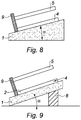
- the figure 8 illustrates another embodiment which differs from previous ones in that the support 1 is not configured to generate a deformation and an inflection region in the lower substrate 2.
- the support 1 is inclined according to the angle d inclination ⁇ as defined above, leading to forming the raised region 4 in the lower substrate 2. It is then possible to proceed to direct bonding by causing the upper substrate 5 to drop under gravity under a vacuum atmosphere, typically less than 100 Pa. , while avoiding the generation of a secondary bonding wave.
- such a support 1 having a receiving surface of the inclined lower substrate 2 can be obtained in various ways such as by providing a support 1 having intrinsically the angle of inclination ⁇ or by providing a support 1 under which a stud 8 is positioned.
- the method of the invention proposes a direct bonding method allowing the initiation of a single bonding wave at a given position.
- This method makes it possible to obtain direct bonding under ambient or vacuum conditions, without using a dedicated device for the application of local pressure, using gravity alone to make contact between the two substrates.
- the method of the invention also makes it possible to control the location of the initiation of bonding on the raised portion of the lower substrate 2 and the prevention of a secondary bonding wave at low pressure, particularly by adjusting the parallelism between the upper substrate 5 and that of the support 1. The invention thus avoids the problem of synchronizing the fall of the upper substrate 5 and the application of the local pressure determining the starting point of the bonding of known techniques.
Claims (15)
- Direktverklebungsverfahren zwischen einem unteren Substrat (2) und einem oberen Substrat (5), umfassend die folgenden Schritte:a) Bereitstellen eines Trägers (1),b) Positionieren des unteren Substrats (2) auf den Träger (1), wobei der Träger konfiguriert ist, um einen Abschnitt (4) des unteren Substrats (2) zu erhöhen,c) Positionieren des oberen Substrats (5) oberhalb des unteren Substrats (2),d) Erlauben des Fallens durch die Schwerkraft des oberen Substrats (5) auf das untere Substrat (2), um einen anfänglichen Kontaktpunkt (6) zwischen dem oberen Substrat (5) und dem unteren Substrat (2) zu bilden, der sich auf dem erhöhten Abschnitt (4) des unteren Substrats (2) befindet, unde) Vervollständigen des In-Kontakt-Bringens des oberen Substrats (5) und des unteren Substrats (2), um das oberen Substrat (5) und das untere Substrat (2) durch Direktverklebung zu verkleben.
- Direktverklebungsverfahren nach Anspruch 1, wobei der Schritt a), das Bereitstellen eines Trägers (1), das Bereitstellen eines Plateaus (10) und eines auf dem Plateau (10) angeordneten Erhöhungselements (3) umfasst, wobei das Plateau (10) und das Erhöhungselement (3) konfiguriert sind, um das untere Substrat (2) durch Schwerkraft zu verformen, um in Schritt b) den erhöhten Abschnitt (4) und einen Flexionsbereich in dem unteren Substrat (2) zu bilden.
- Direktverklebungsverfahren nach Anspruch 2, wobei das Erhöhungselement (3) eine Höhe im Bereich von 0,05 bis 3 mal die Dicke des unteren Substrats (2), und vorzugsweise eine Höhe im Bereich von 0,2 bis 2 mal die Dicke des unteren Substrats (2) aufweist.
- Direktverklebungsverfahren nach einem der Ansprüche 2 bis 3, wobei das Erhöhungselement (3) konfiguriert ist, um höhenverstellbar zu sein und wobei das Verfahren vor dem Schritt d) einen Schritt m) umfasst, der aus dem Verstellen der Höhe des Erhöhungselements (3) besteht.
- Direktverklebungsverfahren nach einem der Ansprüche 2 bis 4, wobei das Erhöhungselement (3) sich über die Dicke des Plateaus (10) erstreckt.
- Direktverklebungsverfahren nach einem der Ansprüche 2 bis 4, wobei das Erhöhungselement (3) ein entfernbares Abstandsstück ist.
- Direktverklebungsverfahren nach einem der Ansprüche 2 bis 4, wobei das Plateau (10) und das Erhöhungselement (3) einstückig sind.
- Direktverklebungsverfahren nach einem der Ansprüche 1 bis 7, wobei der in Schritt a) bereitgestellte Träger (1) einen Aufnahmeabschnitt des unteren Substrats (2) umfasst, wobei der Aufnahmeabschnitt eben ist, und wobei der Schritt c) die Positionierung des oberen Substrats (5) im Wesentlichen parallel zum Aufnahmeabschnitt des Trägers (1) umfasst.
- Direktverklebungsverfahren nach einem der Ansprüche 1 bis 8, umfassend einen Schritt i), durchgeführt vor Schritt b), der aus dem Neigen des Trägers (1), bezogen auf die Horizontale, gemäß einem Neigungswinkel (α) besteht.
- Direktverklebungsverfahren nach Anspruch 9, wobei der Neigungswinkel (α) größer als 0 und kleiner oder gleich als 85° ist, vorzugsweise wobei der Neigungswinkel (α) größer als 0 und kleiner als 45° ist.
- Direktverklebungsverfahren nach einem der Ansprüche 1 bis 10, wobei der Träger (1) mindestens ein Anschlagselement (9) umfasst, konfiguriert, damit mindestens ein Umfangsteil des oberen Substrats (5) und mindestens ein Umfangsteil des unteren Substrats (2) gegen das Anschlagselement (9) ausgerichtet sind, insbesondere in Schritt d) des Verfahrens.
- Direktverklebungsverfahren nach einem der Ansprüche 1 bis 11, umfassend einen Schritt k) des Detektierens der Verklebungswelle zwischen dem unteren Substrat (2) und dem oberen Substrat (5).
- Direktverklebungsverfahren nach Anspruch 12, umfassend einen Schritt l), beinhaltend das Absenken des erhöhten Abschnitts (4) des unteren Substrats (2), wenn die Verklebungswelle detektiert wird.
- Direktverklebungsverfahren nach einem der Ansprüche 2 bis 13, wobei der Schritt d) unter einer Atmosphäre über oder gleich dem Vakuum durchgeführt wird, insbesondere unter einem Druck im Bereich von 100 Pa und 1013 hPa.
- Direktverklebungsverfahren nach einem der Ansprüche 1 bis 13, wobei der Schritt c) unter einer Vakuum-Atmosphäre durchgeführt wird, und insbesondere unter einem Druck unterhalb von 100 Pa.
Applications Claiming Priority (2)
| Application Number | Priority Date | Filing Date | Title |
|---|---|---|---|
| FR1455356A FR3022178B1 (fr) | 2014-06-12 | 2014-06-12 | Procede de collage direct |
| PCT/FR2015/051516 WO2015189513A1 (fr) | 2014-06-12 | 2015-06-09 | Procédé de collage direct |
Publications (2)
| Publication Number | Publication Date |
|---|---|
| EP3155651A1 EP3155651A1 (de) | 2017-04-19 |
| EP3155651B1 true EP3155651B1 (de) | 2018-09-19 |
Family
ID=51688184
Family Applications (1)
| Application Number | Title | Priority Date | Filing Date |
|---|---|---|---|
| EP15736547.9A Not-in-force EP3155651B1 (de) | 2014-06-12 | 2015-06-09 | Direktklebeverfahren |
Country Status (4)
| Country | Link |
|---|---|
| US (1) | US20170120567A1 (de) |
| EP (1) | EP3155651B1 (de) |
| FR (1) | FR3022178B1 (de) |
| WO (1) | WO2015189513A1 (de) |
Families Citing this family (2)
| Publication number | Priority date | Publication date | Assignee | Title |
|---|---|---|---|---|
| EP3382744A1 (de) | 2016-02-16 | 2018-10-03 | EV Group E. Thallner GmbH | Vorrichtung zum bonden von substraten |
| KR20190076956A (ko) * | 2016-10-26 | 2019-07-02 | 에이지씨 가부시키가이샤 | 적층체의 제조 방법 |
Family Cites Families (5)
| Publication number | Priority date | Publication date | Assignee | Title |
|---|---|---|---|---|
| NL8900388A (nl) * | 1989-02-17 | 1990-09-17 | Philips Nv | Werkwijze voor het verbinden van twee voorwerpen. |
| US8035098B1 (en) * | 2006-04-04 | 2011-10-11 | Globalfoundries Inc. | Transistor with asymmetric silicon germanium source region |
| JP2012160628A (ja) * | 2011-02-02 | 2012-08-23 | Sony Corp | 基板の接合方法及び基板接合装置 |
| JP2013008921A (ja) * | 2011-06-27 | 2013-01-10 | Toshiba Corp | 半導体製造装置及び製造方法 |
| US10330328B2 (en) * | 2013-07-22 | 2019-06-25 | Trane International Inc. | Temperature control system |
-
2014
- 2014-06-12 FR FR1455356A patent/FR3022178B1/fr not_active Expired - Fee Related
-
2015
- 2015-06-09 US US15/318,176 patent/US20170120567A1/en not_active Abandoned
- 2015-06-09 EP EP15736547.9A patent/EP3155651B1/de not_active Not-in-force
- 2015-06-09 WO PCT/FR2015/051516 patent/WO2015189513A1/fr active Application Filing
Non-Patent Citations (1)
| Title |
|---|
| None * |
Also Published As
| Publication number | Publication date |
|---|---|
| WO2015189513A1 (fr) | 2015-12-17 |
| FR3022178A1 (fr) | 2015-12-18 |
| US20170120567A1 (en) | 2017-05-04 |
| EP3155651A1 (de) | 2017-04-19 |
| FR3022178B1 (fr) | 2018-02-16 |
Similar Documents
| Publication | Publication Date | Title |
|---|---|---|
| EP1385683B1 (de) | Substratschichtschneidvorrichtung und damit verbundenes verfahren | |
| EP1890958B1 (de) | Mikromechanische komponente mit aktiven elementen und verfahren zur herstellung einer komponente dieser art | |
| FR2963157A1 (fr) | Procede et appareil de collage par adhesion moleculaire de deux plaques | |
| FR2965974A1 (fr) | Procédé de collage moléculaire de substrats en silicium et en verre | |
| EP2434533A1 (de) | Molekulare Verbindung mit reduzierten Overlay Fehlausrichtung | |
| EP2771661B1 (de) | Mikromechanische struktur mit einer verformbaren membran und einem schutz vor starken verformungen | |
| FR2957190A1 (fr) | Procede de realisation d'une structure multicouche avec detourage par effets thermomecaniques. | |
| FR2947380A1 (fr) | Procede de collage par adhesion moleculaire. | |
| FR2935537A1 (fr) | Procede d'initiation d'adhesion moleculaire | |
| EP3155651B1 (de) | Direktklebeverfahren | |
| FR2995447A1 (fr) | Procede de separation d'au moins deux substrats selon une interface choisie | |
| FR3020175A1 (fr) | Procede de transfert d'une couche utile | |
| FR2972078A1 (fr) | Appareil et procédé de collage par adhésion moléculaire | |
| EP3005408A1 (de) | Verfahren zum zusammenfügen von zwei substraten verschiedener beschaffenheit mithilfe einer duktilen zwischenschicht | |
| FR2997224A1 (fr) | Procede de collage par adhesion moleculaire | |
| EP2397530A1 (de) | Dickenkalibriertes Klebeverfahren zwischen mindestens zwei Substraten | |
| EP2798672B1 (de) | Verfahren zur herstellung einer mehrschichtigen struktur auf einem substrat | |
| EP3670439B1 (de) | Gelenk für mikro- und nanoelektrische systeme mit bewegungen ausserhalb der ebene, das eine reduzierte nichtlinearität ermöglicht | |
| FR3060199B1 (fr) | Procede de transfert de couches minces | |
| EP3497713B1 (de) | Verfahren zur übertragung einer nützlichen schicht | |
| EP3035378B1 (de) | Umwandlungsverfahren einer elektronischen vorrichtung verwendbar in einem verfahren des temporären bondens eines wafers auf ein trägersubstrat und elektronische vorrichtung hergestellt durch das verfahren | |
| FR2995445A1 (fr) | Procede de fabrication d'une structure en vue d'une separation ulterieure | |
| EP2798668B1 (de) | Verfahren zur herstellung einer mehrschichtigen struktur auf einem substrat | |
| FR2995440A1 (fr) | Dispositif de separation de deux substrats | |
| FR3099847A1 (fr) | Outil de positionnement |
Legal Events
| Date | Code | Title | Description |
|---|---|---|---|
| STAA | Information on the status of an ep patent application or granted ep patent |
Free format text: STATUS: THE INTERNATIONAL PUBLICATION HAS BEEN MADE |
|
| PUAI | Public reference made under article 153(3) epc to a published international application that has entered the european phase |
Free format text: ORIGINAL CODE: 0009012 |
|
| STAA | Information on the status of an ep patent application or granted ep patent |
Free format text: STATUS: REQUEST FOR EXAMINATION WAS MADE |
|
| 17P | Request for examination filed |
Effective date: 20161208 |
|
| AK | Designated contracting states |
Kind code of ref document: A1 Designated state(s): AL AT BE BG CH CY CZ DE DK EE ES FI FR GB GR HR HU IE IS IT LI LT LU LV MC MK MT NL NO PL PT RO RS SE SI SK SM TR |
|
| AX | Request for extension of the european patent |
Extension state: BA ME |
|
| DAV | Request for validation of the european patent (deleted) | ||
| DAX | Request for extension of the european patent (deleted) | ||
| GRAP | Despatch of communication of intention to grant a patent |
Free format text: ORIGINAL CODE: EPIDOSNIGR1 |
|
| STAA | Information on the status of an ep patent application or granted ep patent |
Free format text: STATUS: GRANT OF PATENT IS INTENDED |
|
| INTG | Intention to grant announced |
Effective date: 20180416 |
|
| GRAS | Grant fee paid |
Free format text: ORIGINAL CODE: EPIDOSNIGR3 |
|
| GRAA | (expected) grant |
Free format text: ORIGINAL CODE: 0009210 |
|
| STAA | Information on the status of an ep patent application or granted ep patent |
Free format text: STATUS: THE PATENT HAS BEEN GRANTED |
|
| AK | Designated contracting states |
Kind code of ref document: B1 Designated state(s): AL AT BE BG CH CY CZ DE DK EE ES FI FR GB GR HR HU IE IS IT LI LT LU LV MC MK MT NL NO PL PT RO RS SE SI SK SM TR |
|
| REG | Reference to a national code |
Ref country code: GB Ref legal event code: FG4D Free format text: NOT ENGLISH |
|
| REG | Reference to a national code |
Ref country code: CH Ref legal event code: EP |
|
| REG | Reference to a national code |
Ref country code: AT Ref legal event code: REF Ref document number: 1044214 Country of ref document: AT Kind code of ref document: T Effective date: 20181015 |
|
| REG | Reference to a national code |
Ref country code: IE Ref legal event code: FG4D Free format text: LANGUAGE OF EP DOCUMENT: FRENCH |
|
| REG | Reference to a national code |
Ref country code: DE Ref legal event code: R096 Ref document number: 602015016649 Country of ref document: DE |
|
| REG | Reference to a national code |
Ref country code: NL Ref legal event code: MP Effective date: 20180919 |
|
| PG25 | Lapsed in a contracting state [announced via postgrant information from national office to epo] |
Ref country code: LT Free format text: LAPSE BECAUSE OF FAILURE TO SUBMIT A TRANSLATION OF THE DESCRIPTION OR TO PAY THE FEE WITHIN THE PRESCRIBED TIME-LIMIT Effective date: 20180919 Ref country code: BG Free format text: LAPSE BECAUSE OF FAILURE TO SUBMIT A TRANSLATION OF THE DESCRIPTION OR TO PAY THE FEE WITHIN THE PRESCRIBED TIME-LIMIT Effective date: 20181219 Ref country code: GR Free format text: LAPSE BECAUSE OF FAILURE TO SUBMIT A TRANSLATION OF THE DESCRIPTION OR TO PAY THE FEE WITHIN THE PRESCRIBED TIME-LIMIT Effective date: 20181220 Ref country code: NO Free format text: LAPSE BECAUSE OF FAILURE TO SUBMIT A TRANSLATION OF THE DESCRIPTION OR TO PAY THE FEE WITHIN THE PRESCRIBED TIME-LIMIT Effective date: 20181219 Ref country code: SE Free format text: LAPSE BECAUSE OF FAILURE TO SUBMIT A TRANSLATION OF THE DESCRIPTION OR TO PAY THE FEE WITHIN THE PRESCRIBED TIME-LIMIT Effective date: 20180919 Ref country code: RS Free format text: LAPSE BECAUSE OF FAILURE TO SUBMIT A TRANSLATION OF THE DESCRIPTION OR TO PAY THE FEE WITHIN THE PRESCRIBED TIME-LIMIT Effective date: 20180919 Ref country code: FI Free format text: LAPSE BECAUSE OF FAILURE TO SUBMIT A TRANSLATION OF THE DESCRIPTION OR TO PAY THE FEE WITHIN THE PRESCRIBED TIME-LIMIT Effective date: 20180919 |
|
| REG | Reference to a national code |
Ref country code: LT Ref legal event code: MG4D |
|
| PG25 | Lapsed in a contracting state [announced via postgrant information from national office to epo] |
Ref country code: AL Free format text: LAPSE BECAUSE OF FAILURE TO SUBMIT A TRANSLATION OF THE DESCRIPTION OR TO PAY THE FEE WITHIN THE PRESCRIBED TIME-LIMIT Effective date: 20180919 Ref country code: HR Free format text: LAPSE BECAUSE OF FAILURE TO SUBMIT A TRANSLATION OF THE DESCRIPTION OR TO PAY THE FEE WITHIN THE PRESCRIBED TIME-LIMIT Effective date: 20180919 Ref country code: LV Free format text: LAPSE BECAUSE OF FAILURE TO SUBMIT A TRANSLATION OF THE DESCRIPTION OR TO PAY THE FEE WITHIN THE PRESCRIBED TIME-LIMIT Effective date: 20180919 |
|
| REG | Reference to a national code |
Ref country code: AT Ref legal event code: MK05 Ref document number: 1044214 Country of ref document: AT Kind code of ref document: T Effective date: 20180919 |
|
| PG25 | Lapsed in a contracting state [announced via postgrant information from national office to epo] |
Ref country code: AT Free format text: LAPSE BECAUSE OF FAILURE TO SUBMIT A TRANSLATION OF THE DESCRIPTION OR TO PAY THE FEE WITHIN THE PRESCRIBED TIME-LIMIT Effective date: 20180919 Ref country code: IT Free format text: LAPSE BECAUSE OF FAILURE TO SUBMIT A TRANSLATION OF THE DESCRIPTION OR TO PAY THE FEE WITHIN THE PRESCRIBED TIME-LIMIT Effective date: 20180919 Ref country code: EE Free format text: LAPSE BECAUSE OF FAILURE TO SUBMIT A TRANSLATION OF THE DESCRIPTION OR TO PAY THE FEE WITHIN THE PRESCRIBED TIME-LIMIT Effective date: 20180919 Ref country code: PL Free format text: LAPSE BECAUSE OF FAILURE TO SUBMIT A TRANSLATION OF THE DESCRIPTION OR TO PAY THE FEE WITHIN THE PRESCRIBED TIME-LIMIT Effective date: 20180919 Ref country code: CZ Free format text: LAPSE BECAUSE OF FAILURE TO SUBMIT A TRANSLATION OF THE DESCRIPTION OR TO PAY THE FEE WITHIN THE PRESCRIBED TIME-LIMIT Effective date: 20180919 Ref country code: IS Free format text: LAPSE BECAUSE OF FAILURE TO SUBMIT A TRANSLATION OF THE DESCRIPTION OR TO PAY THE FEE WITHIN THE PRESCRIBED TIME-LIMIT Effective date: 20190119 Ref country code: RO Free format text: LAPSE BECAUSE OF FAILURE TO SUBMIT A TRANSLATION OF THE DESCRIPTION OR TO PAY THE FEE WITHIN THE PRESCRIBED TIME-LIMIT Effective date: 20180919 Ref country code: NL Free format text: LAPSE BECAUSE OF FAILURE TO SUBMIT A TRANSLATION OF THE DESCRIPTION OR TO PAY THE FEE WITHIN THE PRESCRIBED TIME-LIMIT Effective date: 20180919 Ref country code: ES Free format text: LAPSE BECAUSE OF FAILURE TO SUBMIT A TRANSLATION OF THE DESCRIPTION OR TO PAY THE FEE WITHIN THE PRESCRIBED TIME-LIMIT Effective date: 20180919 |
|
| PG25 | Lapsed in a contracting state [announced via postgrant information from national office to epo] |
Ref country code: PT Free format text: LAPSE BECAUSE OF FAILURE TO SUBMIT A TRANSLATION OF THE DESCRIPTION OR TO PAY THE FEE WITHIN THE PRESCRIBED TIME-LIMIT Effective date: 20190119 Ref country code: SK Free format text: LAPSE BECAUSE OF FAILURE TO SUBMIT A TRANSLATION OF THE DESCRIPTION OR TO PAY THE FEE WITHIN THE PRESCRIBED TIME-LIMIT Effective date: 20180919 Ref country code: SM Free format text: LAPSE BECAUSE OF FAILURE TO SUBMIT A TRANSLATION OF THE DESCRIPTION OR TO PAY THE FEE WITHIN THE PRESCRIBED TIME-LIMIT Effective date: 20180919 |
|
| REG | Reference to a national code |
Ref country code: DE Ref legal event code: R097 Ref document number: 602015016649 Country of ref document: DE |
|
| PLBE | No opposition filed within time limit |
Free format text: ORIGINAL CODE: 0009261 |
|
| STAA | Information on the status of an ep patent application or granted ep patent |
Free format text: STATUS: NO OPPOSITION FILED WITHIN TIME LIMIT |
|
| PG25 | Lapsed in a contracting state [announced via postgrant information from national office to epo] |
Ref country code: DK Free format text: LAPSE BECAUSE OF FAILURE TO SUBMIT A TRANSLATION OF THE DESCRIPTION OR TO PAY THE FEE WITHIN THE PRESCRIBED TIME-LIMIT Effective date: 20180919 |
|
| 26N | No opposition filed |
Effective date: 20190620 |
|
| PG25 | Lapsed in a contracting state [announced via postgrant information from national office to epo] |
Ref country code: SI Free format text: LAPSE BECAUSE OF FAILURE TO SUBMIT A TRANSLATION OF THE DESCRIPTION OR TO PAY THE FEE WITHIN THE PRESCRIBED TIME-LIMIT Effective date: 20180919 |
|
| REG | Reference to a national code |
Ref country code: DE Ref legal event code: R119 Ref document number: 602015016649 Country of ref document: DE |
|
| PG25 | Lapsed in a contracting state [announced via postgrant information from national office to epo] |
Ref country code: MC Free format text: LAPSE BECAUSE OF FAILURE TO SUBMIT A TRANSLATION OF THE DESCRIPTION OR TO PAY THE FEE WITHIN THE PRESCRIBED TIME-LIMIT Effective date: 20180919 |
|
| REG | Reference to a national code |
Ref country code: CH Ref legal event code: PL |
|
| GBPC | Gb: european patent ceased through non-payment of renewal fee |
Effective date: 20190609 |
|
| REG | Reference to a national code |
Ref country code: BE Ref legal event code: MM Effective date: 20190630 |
|
| PG25 | Lapsed in a contracting state [announced via postgrant information from national office to epo] |
Ref country code: TR Free format text: LAPSE BECAUSE OF FAILURE TO SUBMIT A TRANSLATION OF THE DESCRIPTION OR TO PAY THE FEE WITHIN THE PRESCRIBED TIME-LIMIT Effective date: 20180919 |
|
| PG25 | Lapsed in a contracting state [announced via postgrant information from national office to epo] |
Ref country code: IE Free format text: LAPSE BECAUSE OF NON-PAYMENT OF DUE FEES Effective date: 20190609 Ref country code: DE Free format text: LAPSE BECAUSE OF NON-PAYMENT OF DUE FEES Effective date: 20200101 Ref country code: GB Free format text: LAPSE BECAUSE OF NON-PAYMENT OF DUE FEES Effective date: 20190609 |
|
| PG25 | Lapsed in a contracting state [announced via postgrant information from national office to epo] |
Ref country code: BE Free format text: LAPSE BECAUSE OF NON-PAYMENT OF DUE FEES Effective date: 20190630 Ref country code: CH Free format text: LAPSE BECAUSE OF NON-PAYMENT OF DUE FEES Effective date: 20190630 Ref country code: LI Free format text: LAPSE BECAUSE OF NON-PAYMENT OF DUE FEES Effective date: 20190630 Ref country code: LU Free format text: LAPSE BECAUSE OF NON-PAYMENT OF DUE FEES Effective date: 20190609 |
|
| PG25 | Lapsed in a contracting state [announced via postgrant information from national office to epo] |
Ref country code: FR Free format text: LAPSE BECAUSE OF NON-PAYMENT OF DUE FEES Effective date: 20190630 |
|
| PG25 | Lapsed in a contracting state [announced via postgrant information from national office to epo] |
Ref country code: CY Free format text: LAPSE BECAUSE OF FAILURE TO SUBMIT A TRANSLATION OF THE DESCRIPTION OR TO PAY THE FEE WITHIN THE PRESCRIBED TIME-LIMIT Effective date: 20180919 |
|
| PG25 | Lapsed in a contracting state [announced via postgrant information from national office to epo] |
Ref country code: HU Free format text: LAPSE BECAUSE OF FAILURE TO SUBMIT A TRANSLATION OF THE DESCRIPTION OR TO PAY THE FEE WITHIN THE PRESCRIBED TIME-LIMIT; INVALID AB INITIO Effective date: 20150609 Ref country code: MT Free format text: LAPSE BECAUSE OF FAILURE TO SUBMIT A TRANSLATION OF THE DESCRIPTION OR TO PAY THE FEE WITHIN THE PRESCRIBED TIME-LIMIT Effective date: 20180919 |
|
| PG25 | Lapsed in a contracting state [announced via postgrant information from national office to epo] |
Ref country code: MK Free format text: LAPSE BECAUSE OF FAILURE TO SUBMIT A TRANSLATION OF THE DESCRIPTION OR TO PAY THE FEE WITHIN THE PRESCRIBED TIME-LIMIT Effective date: 20180919 |