EP3155200B1 - Abstandhalterrahmen und verfahren zur herstellung davon - Google Patents
Abstandhalterrahmen und verfahren zur herstellung davon Download PDFInfo
- Publication number
- EP3155200B1 EP3155200B1 EP15806949.2A EP15806949A EP3155200B1 EP 3155200 B1 EP3155200 B1 EP 3155200B1 EP 15806949 A EP15806949 A EP 15806949A EP 3155200 B1 EP3155200 B1 EP 3155200B1
- Authority
- EP
- European Patent Office
- Prior art keywords
- spacer frame
- frame assembly
- spacer
- strip
- assembly
- Prior art date
- Legal status (The legal status is an assumption and is not a legal conclusion. Google has not performed a legal analysis and makes no representation as to the accuracy of the status listed.)
- Active
Links
Images


Classifications
-
- E—FIXED CONSTRUCTIONS
- E04—BUILDING
- E04B—GENERAL BUILDING CONSTRUCTIONS; WALLS, e.g. PARTITIONS; ROOFS; FLOORS; CEILINGS; INSULATION OR OTHER PROTECTION OF BUILDINGS
- E04B1/00—Constructions in general; Structures which are not restricted either to walls, e.g. partitions, or floors or ceilings or roofs
- E04B1/02—Structures consisting primarily of load-supporting, block-shaped, or slab-shaped elements
- E04B1/10—Structures consisting primarily of load-supporting, block-shaped, or slab-shaped elements the elements consisting of wood
-
- E—FIXED CONSTRUCTIONS
- E04—BUILDING
- E04B—GENERAL BUILDING CONSTRUCTIONS; WALLS, e.g. PARTITIONS; ROOFS; FLOORS; CEILINGS; INSULATION OR OTHER PROTECTION OF BUILDINGS
- E04B1/00—Constructions in general; Structures which are not restricted either to walls, e.g. partitions, or floors or ceilings or roofs
-
- E—FIXED CONSTRUCTIONS
- E04—BUILDING
- E04B—GENERAL BUILDING CONSTRUCTIONS; WALLS, e.g. PARTITIONS; ROOFS; FLOORS; CEILINGS; INSULATION OR OTHER PROTECTION OF BUILDINGS
- E04B5/00—Floors; Floor construction with regard to insulation; Connections specially adapted therefor
- E04B5/02—Load-carrying floor structures formed substantially of prefabricated units
- E04B5/10—Load-carrying floor structures formed substantially of prefabricated units with metal beams or girders, e.g. with steel lattice girders
-
- E—FIXED CONSTRUCTIONS
- E06—DOORS, WINDOWS, SHUTTERS, OR ROLLER BLINDS IN GENERAL; LADDERS
- E06B—FIXED OR MOVABLE CLOSURES FOR OPENINGS IN BUILDINGS, VEHICLES, FENCES OR LIKE ENCLOSURES IN GENERAL, e.g. DOORS, WINDOWS, BLINDS, GATES
- E06B3/00—Window sashes, door leaves, or like elements for closing wall or like openings; Layout of fixed or moving closures, e.g. windows in wall or like openings; Features of rigidly-mounted outer frames relating to the mounting of wing frames
- E06B3/66—Units comprising two or more parallel glass or like panes permanently secured together
- E06B3/663—Elements for spacing panes
- E06B3/66309—Section members positioned at the edges of the glazing unit
-
- E—FIXED CONSTRUCTIONS
- E06—DOORS, WINDOWS, SHUTTERS, OR ROLLER BLINDS IN GENERAL; LADDERS
- E06B—FIXED OR MOVABLE CLOSURES FOR OPENINGS IN BUILDINGS, VEHICLES, FENCES OR LIKE ENCLOSURES IN GENERAL, e.g. DOORS, WINDOWS, BLINDS, GATES
- E06B3/00—Window sashes, door leaves, or like elements for closing wall or like openings; Layout of fixed or moving closures, e.g. windows in wall or like openings; Features of rigidly-mounted outer frames relating to the mounting of wing frames
- E06B3/66—Units comprising two or more parallel glass or like panes permanently secured together
- E06B3/673—Assembling the units
- E06B3/67304—Preparing rigid spacer members before assembly
- E06B3/67308—Making spacer frames, e.g. by bending or assembling straight sections
- E06B3/67313—Making spacer frames, e.g. by bending or assembling straight sections by bending
-
- Y—GENERAL TAGGING OF NEW TECHNOLOGICAL DEVELOPMENTS; GENERAL TAGGING OF CROSS-SECTIONAL TECHNOLOGIES SPANNING OVER SEVERAL SECTIONS OF THE IPC; TECHNICAL SUBJECTS COVERED BY FORMER USPC CROSS-REFERENCE ART COLLECTIONS [XRACs] AND DIGESTS
- Y02—TECHNOLOGIES OR APPLICATIONS FOR MITIGATION OR ADAPTATION AGAINST CLIMATE CHANGE
- Y02A—TECHNOLOGIES FOR ADAPTATION TO CLIMATE CHANGE
- Y02A30/00—Adapting or protecting infrastructure or their operation
- Y02A30/24—Structural elements or technologies for improving thermal insulation
- Y02A30/249—Glazing, e.g. vacuum glazing
-
- Y—GENERAL TAGGING OF NEW TECHNOLOGICAL DEVELOPMENTS; GENERAL TAGGING OF CROSS-SECTIONAL TECHNOLOGIES SPANNING OVER SEVERAL SECTIONS OF THE IPC; TECHNICAL SUBJECTS COVERED BY FORMER USPC CROSS-REFERENCE ART COLLECTIONS [XRACs] AND DIGESTS
- Y02—TECHNOLOGIES OR APPLICATIONS FOR MITIGATION OR ADAPTATION AGAINST CLIMATE CHANGE
- Y02B—CLIMATE CHANGE MITIGATION TECHNOLOGIES RELATED TO BUILDINGS, e.g. HOUSING, HOUSE APPLIANCES OR RELATED END-USER APPLICATIONS
- Y02B80/00—Architectural or constructional elements improving the thermal performance of buildings
- Y02B80/22—Glazing, e.g. vaccum glazing
-
- Y—GENERAL TAGGING OF NEW TECHNOLOGICAL DEVELOPMENTS; GENERAL TAGGING OF CROSS-SECTIONAL TECHNOLOGIES SPANNING OVER SEVERAL SECTIONS OF THE IPC; TECHNICAL SUBJECTS COVERED BY FORMER USPC CROSS-REFERENCE ART COLLECTIONS [XRACs] AND DIGESTS
- Y10—TECHNICAL SUBJECTS COVERED BY FORMER USPC
- Y10T—TECHNICAL SUBJECTS COVERED BY FORMER US CLASSIFICATION
- Y10T29/00—Metal working
- Y10T29/49—Method of mechanical manufacture
- Y10T29/4998—Combined manufacture including applying or shaping of fluent material
- Y10T29/49982—Coating
Definitions
- the present disclosure relates to a spacer frame assembly for bending into a multi-sided window or door spacer frame and a method of making the same.
- IGUs Insulating glass units
- a spacer assembly usually comprises a frame structure extending peripherally about the unit, a sealant material adhered both to the glass lites and the frame structure, and a desiccant for absorbing atmospheric moisture within the unit.
- the margins of the glass lifts are flush with or extend slightly outwardly from the spacer assembly.
- the sealant extends continuously about the frame structure periphery and its opposite sides so that the space within the IGUs is hermetic.
- IGUs There have been numerous proposals for constructing IGUs.
- One type of IGU was constructed from an elongated corrugated sheet metal strip-like frame embedded in a body of hot melt or sealant material. Desiccant was also embedded in the sealant.
- the resulting composite spacer was packaged for transport and storage by coiling it into drum-like containers. When fabricating an IGU, the composite spacer was partially uncoiled and cut to length. The spacer was then bent into a rectangular shape and sandwiched between conforming glass lites.
- tubular, roll formed aluminum or steel frame elements connected at their ends to form a square or rectangular spacer frame.
- the frame sides and corners were covered with sealant (e.g ., butyl material, hot melt, reactive hot meh, or modified polyurethane) for securing the frame to the glass lites.
- sealant e.g ., butyl material, hot melt, reactive hot meh, or modified polyurethane
- the sealant provided a barrier between atmospheric air and the IGU interior which blocked entry of atmospheric water vapor.
- Particulate desiccant deposited inside the tubular frame elements communicated with air trapped in the IGU interior to remove the entrapped airborne water vapor and thus preclude its condensation within the unit. Thus, after the water vapor entrapped in the IGU was removed internal condensation only occurred when the unit failed.
- the sheet metal was roll formed into a continuous tube, with desiccant inserted, and fed to cutting stations where "V" shaped notches were cut in the tube at corner locations.
- the tube was then cut to length and bent into an appropriate frame shape.
- corner keys were foldable so that the sealant could be extruded onto the frame sides as the frame moved linearly past a sealant extrusion station.
- the frame was then folded to a rectangular configuration with the sealant in place on the opposite sides.
- the spacer assembly thus formed was placed between glass lites and the IGU assembly completed.
- IGUs have foiled because atmospheric water vapor infiltrated the sealant barrier. Infiltration tended to occur at the frame corners because the opposite frame sides were at least partly discontinuous there. For example, frames where the corners were formed by cutting "V" shaped notches at corner locations in a single long tube. The notches enabled bending the tube to form mitered corner joints; but afterwards potential infiltration paths extended along the corner parting lines substantially across the opposite frame faces at each corner.
- U.S. Patent. No. 5,361,476 to Leopold discloses a method and apparatus for making IGUs wherein a thin flat strip of sheet material is continuously formed into a channel shaped spacer frame having corner structures and end structures, the spacer thus formed is cut off, sealant and desiccant are applied and the assemblage is bent to form a spacer assembly.
- U.S. Patent. No. 7,448,246 to Briese et al. further describes the process of corner fabrication of a spacer frame.
- U.S. Pat. No. 8,720,026 to McGlinchy discusses additional methods of producing spacer flames.
- DE102004027527A1 and US5644894A disclose a spacer frame assembly for bending into a multi-sided window or door spacer frame.
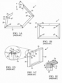
- FIGS. 1A-1E Illustrated in FIGS. 1A-1E is a conventional spacer frame 1 fabricated for IGUs.
- the conventional spacer frame 1 is typically fabricated from an elongated metal strip and roll-formed into the orientation shown.
- the conventional spacer frame 1 includes five different legs, 2a, 2b, 2c, 2d, and 2e.
- Leg 2a is a tab that when the spacer frame is assembled is inserted into leg 2e to form a corner juncture or connection at CJ.
- Logs 2b-2e make up the four sides of the spacer frame.
- the leg 2e includes a chamfered end 3, typically as an angle ⁇ of 45 degrees from a longitudinal axis "LA" that extends along the center of leg 2e. This allows the tab leg 2a to be completely inserted into leg 2e until end sides 3a and 3c of the leg 2e bottom out on corresponding ends 3b and 3d to form corner juncture CJ.
- the conventional spacer frame 1 In the assembled position, the conventional spacer frame 1 includes four gaps g1, g2, g3, and g4.
- the gap gl is formed by fee legs 2a and 2b and the passage the sliding of leg 2e over the leg 2a at end 3 of the corner juncture CJ.
- FIG. 1e illustrates that the conventional spacer frame typically requires the passage of hot melt or sealant 4 along directions A and B along the end of the frame such that the corner juncture CJ is sealed along two directions.
- One aspect of the disclosure comprises a spacer frame assembly according to claim 1 for bending into a multi-sided window or door spacer frame.
- Another aspect of the present disclosure includes a method of making a spacer frame assembly according to claim 12 for bending into a multi-sided window or door spacer frame.
- the present disclosure relates to a spacer frame and method of making same, and more specifically, a spacer frame and fabrication process for use with an insulating glass unit ("IGU").
- IGU insulating glass unit
- the drawing Figures and following specification disclose a method and apparatus for producing elongated window components 8 (see FIG. 2 ) used in insulating glass units 10.
- elongated window components include spacer frame assemblies 12 and muntin bars 130 that form parts of insulating glass units 10.
- the IGV components 8 are formed in one example embodiment from a production line which forms sheet metal ribbon-like stock material into muntin bars and/or spacers carrying sealant and desiccant for completing the construction of insulating glass units.
- FIG. 2A Illustrated in FIG. 2A is a schematic block diagram of a production line for manufacturing a conventional spacer frame and insulating glass unit as former described in U.S. Patent No. 7,610,681 .
- the production line 100 may be used to fabricate the insulating glass units 10 and spacer frame assemblies 12 of the present disclosure.
- a stock strip 48 of material is fed endwise from a coil from a supply station into the production line 100 and substantially completed elongated window components 8 emerge from the other end of the line.
- the production line 100 comprises a stock supply station 102, a stamping station 104 where various notches, hole indentations or lines of weaknesses, and tab profiles are punched into flat stock 48, a forming station 106 where the flat stock 48 is roll formed to make a u-shaped channel, a crimping station 108 where corners are formed and swaging is performed on the u-shaped channel, a shearing 110 station where the individual spacer frames are separated from the flat stock and cut to length, a desiccant application station 112 where desiccant is applied between glass lites and the interior region formed by the lites and spacer frame assembly, and an extrusion station 114 where sealant is applied to the yet to be folded frame.
- dies on opposite side of the strip 48 are driven into contact with the metal strip by an air actuated drive cylinder enclosed within the stamping station.
- an air actuated drive cylinder enclosed within the stamping station.
- two air actuated cylinders drive a die support downward, moving spaced apart dies into engagement with the strip 48 to form the punch strip 36, which is backed by an anvil in the region of contact with the dies. Due to the need to fabricate spacer frame assemblies 12 of different width between the side walls, 42, 44, the dies are movable with respect to each other so that the region of contact between die and strip 48 is controlled.
- the nose portion or tab 34 of the spacer frame assembly 12 engages the punch strip 36 at controlled locations to form the nose profile seen in FIG. 4A .
- stamping of the nose or tab 34 occurs at a separate time from stamping of the corners at the notches 50.
- the four corners 32 are formed by a first die set controlled by controller 101 that also controls each station of the production line 100 and the nose or tab 34 is formed at another time by a separated air cylinder drive that moves a separate die pair into contact with the punch strip 36. Coordination of these separate actuations is controlled by movement of punch the strip 36 through the stamping station 104 to appropriate positions for forming the corners and the nose portion of the spacer frame.
- FIG. 2 An insulating glass unit 10 illustrated in FIG. 2 is constructed using the method and apparatus further described in FIG. 2A as discussed above and in U.S. Patent No. 8,720,026 and 7,448,246 .
- the IGU 10 comprises a spacer frame assembly 12 sandwiched between glass sheets, or lites, 14.
- the spacer frame assembly 12 comprises a frame structure 16, sealant material 18 for hermetically joining the frame to the lites to form a closed space 20 within the unit 10 and a body 22 of desiccant in the space 20, as illustrated in FIG. 3 .
- the insulating glass unit 10 is illustrated in FIG. 1 as in condition for final assembly into a window or door frame, not illustrated, for ultimate installation in a building.
- the unit 10 illustrated in FIG. 2 includes muntin bars 130 that provide the appearance of individual window panes.
- the assembly 12 maintains the lites 14 spaced apart from each other to produce the hermetic insulating "insulating air space" 20 between them.
- the frame 16 and the sealant body 18 co-act to provide a structure which maintains the lites 14 properly assembled with the space 20 sealed from atmospheric moisture over long time periods during which the unit 10 is subjected to frequent significant thermal stresses.
- the desiccant body 22 removes water vapor from air, or other volatiles, entrapped in the space 20 during construction of the unit 10.
- the sealant body 18 both structurally adheres the lites 14 to the spacer assembly 12 and hermetically closes the space 20 against infiltration of airborne water vapor from the atmosphere surrounding the unit 10.
- the illustrated body or sealant 18 is formed from a number of different possible materials, including for example, butyl material, hot melt, reactive hot melt, modified polyurethane sealant, and the like, which is attached to the frame sides and outer periphery to form a U-shaped cross section.
- the spacer frame assembly 16 extends about the unit periphery to provide a structurally strong, stable spacer for maintaining the lites aligned and spaced while minimizing heat conduction between the lites via the frame.
- the spacer frame 16 comprises a plurality of spacer frame segments, or members, 30a-d connected to form a planar, polygonal frame shape, element juncture forming frame corner structures 32a-d, and connecting structure or tab 34 for joining opposite frame element ends or tail 30d to complete the closed frame shape ( see FIG. 7 ).
- Each frame member 30 is elongated and has a channel shaped cross section defining a peripheral wall 40 and first and second lateral walls 42, 44. See FIGS. 2 and 6 .
- the peripheral wall 40 extends continuously about the unit 10 except where the connecting structure or tab 34 Joins the frame member and 30d.
- the lateral walls 42, 44 are integral with respective opposite peripheral wall 40 edges.
- the lateral walls 42, 44 extend inwardly from the peripheral wall 40 in a direction parallel to the planes of the lites and the frame.
- the illustrated frame 16 has stiffening flanges 46 formed along the inwardly projecting lateral wall 42, 44 edges.
- the lateral walls 42, 44 add rigidity to the frame member 30 so it resists flexure and bending in a direction transverse to its longitudinal extent.
- the flanges 46 stiffen the walls 42, 44 so they resist bending and flexure transverse to their longitudinal extents.
- the frame is initially formed as a continuous straight channel constructed from a thin ribbon of metal or flat stock 48.
- suitable metal includes stainless steel material having a thickness of 0.006-0.010 inches.
- Other materials, such as galvanized, tin plated steel, or aluminum, plastic, or foam may also be used to construct the channel without departing from the scope of the present disclosure.
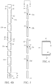
- FIG. 4A Illustrated in FIG. 4A is a continuous metal ribbon or flat stock 48 after it has_passed through a stamping station and punched by a number of dies to form notches 50 and weakening zones 52 for corner folds 32, clip notches 66 (used in securing mutin bars), tab or connecting structure 34, nose 62, apertures 70, 72, and end cut 80.
- the punch strip 36 of flat stock forms a single spacer frame assembly 16 as illustrated in repeating sections by dimension "L" from the continuous strip 48.
- the punch strip 36 is eventually sheared to make a spacer frame assembly 16 at end 80 and the nose 62, leaving scrap piece 82.
- the punching or shearing operation is a single hit operation in which the width of the shear equals that of scrap piece 82, leaving no scrap or need for a double hit operation. Further discussion relating to the shearing or punching operation is discussed in U.S. Patent No. 8,720,026 .
- the nose or tab 34 and stops 64 are formed by stamping dies at a stamping station 104 as described above. Shown by dimension “g" in one example embodiment is a nose or tab 34 width, which is smaller than the width of the stop 64 illustrated by dimension "h” in FiG.4A . In one example embodiment, the width of the nose or tab 34 shown by dimension a is one inch 1.00" and the width of the stops 64 shown by dimension b is one and three sixteenths of one inch 1.187". Thus, the difference between the width of the nose 34 and stops 64 of the above example embodiment is approximately ninety-three thousands .093" of one inch from the outside edge of the strip.
- Clip notches 66 are formed to support flexible clips that reside within the spacer frame assembly 16 and IGU once assembled.
- the flexible clips are used to support, for example, mutin bars as further discussed in U.S. Patent No. 5, 678, 377 .
- Notches 50 and weakening zones 32 are punched and crimped into the continuous strip 48, allowing for the formation of the corner structures 32. Further discussion of the punching and crimping operations is discussed In U.S. Patent No. 7,448,246 .
- the corner structures 32 are formed to facilitate bending the frame channel to the final, polygonal frame configuration in the unit 10 while assuring an effective vapor seal at the frame corners, as seen in FIGS. 2 and 7 .
- the sealant body 18 is applied and adhered to the channel before the corners are bent.
- the corner structures 32 initially comprise notches 50 and weakened zones 52 formed in the walls 42, 44 at frame corner locations. See FIGS. 3-5 .
- the notches 50 extend into the walls 42, 44 from the respective lateral wall edges.
- the lateral walls 42, 44 extend continuously along the frame 16 from one end to the other.
- the walls 42, 44 are weakened at the corner locations because the notches reduce the amount of lateral wall material and eliminate the stiffening flanges 46 and because the walls are stamped to form a line of weakness 53 (see FIG. 5 ) to weaken them at the corners and inward flexing as the corners are formed.
- the connecting structure or tab 34 secures an opposite frame and 54 or leg member 30d together with a first frame and 56 when the spacer frame assembly 16 has been bent to its final configuration. That is, rotating the linear spacer frame assembly 16 segments or members 30 (from the linear configuration of FIGS. 4B and 5 ) in the direction of arrows A, B, C, and D as illustrated in FIG. 7 and particularly, inserting a nose 62 of the connecting structure or tab 34 into the channel formed at the opposite end 54 of segment 30d with concomitant rotation of the segments (arrows A-D). This concomitant rotation continues until the channel of segment 30d at the opposite and 54 engages positive stops 64 in the connecting structure 34 first frame and 56 forming a telescopic union 58 and lateral connection 60 to make a compound lateral leg 31.
- the telescopic union 58 and lateral connection 60 are along the lateral leg 31 spaced from the corner structures 32, which in the illustrated example embodiment of FIG. 7 the completed frame corner is C1.
- the telescopic union 58 maintains the frame in its final polygonal configuration prior to assembly of the insulating glass unit 10.
- the compound lateral leg 31 has a length of dimensions "a" (first frame end 56 from the corner Cl to the end of the stop 64) plus "b" (the fourth frame segment or member 30d), which equals the length of dimension "c” ( see FIG. 7 ), the length of a second and opposite side segment 30b.
- Dimension "b” in the illustrated example embodiment is the length of segment 30d and dimension "a” is the length of the connecting structure 34 less the length of the nose 62 (dimension d) that is inserted into the channel formed in segment 30d.
- the connector structure 34 farther comprises a first aperture 70 and corresponding second aperture 72 in the segment 30d for a fastener arrangement (not shown) for both connecting the opposite frame and 34 with the first frame end 36 and providing a temporary vent for the evacuation of air or insertion of gas into the space 20 while the unit 10 is being fabricated.
- the apertures 70 and 72 are automatically aligned because of the configurable dimensions A and B that when summed equal C ( see FIG. 7 ) when the frame ends 54, 56 are properly telescoped together and the and 34 engages stops 64.
- the stops 64 reassure concentric alignment of the apertures 70, 72.
- the stops 64 further reassure a repeatable length of the telescopic union of the lateral connection 60. This advantageously reassures that all four corner structures 32 are identical in spacing, size, angle orientation, and construction, thus reducing the potential for failure.
- over and under extension of the corners readily occurs. This over and under extension in convention frames Is in part because of differences in tolerances because the last connecting leg 2e (see FIGS. 1C-1D ) fails to bottom out, leaving a gaps d and w in FIG. 1D .
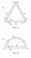
- FIG. 7A is an elevation view of a three sided spacer frame assembly 16 constructed in accordance with one example embodiment of the present disclosure.
- the three sided 30a, 30b, and 30c frame 16 includes a connecting structure or tab 34, a lateral connection 60 spaced from a corner, union point 58, and stops 64 of similar construction of the example embodiment of FIG. 7 .
- FIG. 7B is an elevation view of a two sided spacer frame assembly 16 not forming part of the present invention.
- the two sided 30a and 30b frame 16 includes a connecting structure or tab 34, a lateral connection 60 spaced from a corner, union point 58, and stops 64 of similar construction of the example embodiment of FIG. 7 .
- configurable dimensions "a” and “b” (see FIG. 7 ) further provide assurance that the corner segments 32a-32d are all equally spaced and orthogonal, reducing any spacing or gaps on the lateral walls 42, 44, peripheral wall 40 in the space from corner union point 58 or lateral connection 60, thus reducing the opportunity for failure.
- Configurable dimensions "a”, “b”, and “c” are controlled by a controller or CPU in the firmware or software at [[a]] the crimping station 108 (see FIGS. 2A , 4A , and 7 ), such that the tightest dimensions can be held at the lateral connection 60 and at the corner segments 32.
- configurable dimensions A 2 and L 3 see FIG.
- tab 34 profile is configurable through a mechanical setup, and it is therefore possible to control A1 ( see FIG. 10H ) in order to minimize the clearance between the back of the spacer and stiffening flanges 46, which will minimize clearance when the tab 34 is inserted into the spacer 54 of the final member 30d-. This makes it possible to achieve a minimal clearance between the stiffening flanges 46 and the tab 34 when the spacer frame is assembled as shown in FIG. 10K .
- the width w of the tab 34 varies to a tapered fit such that it is relatively thinner (or swaged by a crimping operation after roll forming) along length L 1 in FIGS. 10H and 10I for ease of assembly. That is, along length L 1 , the width w of tab 34 is approximately .020" smaller than the opening 92 at the opposite end frame 54. Thus, the tab 34 is easily inserted into the last segment 30d as illustrated in FIGS. 10A- 10C (in direction of arrow A). As the tab 34 proceed along its length L 2 . the width w 1 of the tab widens as illustrated in FIGS.
- This tapered formation of the tab 34 occurs by swaging the front portion L 1 by, for example a crimping operation to make the width w of L 1 smaller than the width wi of L 2 .
- the resistance increases as the tab proceeds to enter the opening passed Li, into the L 2 region as illustrated in FIG. 10H .
- FIG. 10L is spacer frame having stops 64 of a spacer frame assembly 16 constructed in accordance with another example embodiment of the present disclosure.
- the stops 64 project or extend outwardly from the lateral walls 42 and 44 of the nose or connecting structure tab 34 and engage the stiffening flanges 46 of the opposite end 54 of the connecting leg 30d.
- the stops 64 in FIG. 10L are constructed by the configuration of the dies in stamping station 104.
- FIG. 10M is a spacer frame having a stop 64 constructed in accordance with another example embodiment of the present disclosure. More particularly, the stop 64 extends outward and transversely to the peripheral wall 40 from the nose or tab 34. In the illustrated example embodiment, the stop 64 is a dent or bump formed without an opening in the peripheral wall by a pressing die in the production line 100. The stop 64 engages or contacts the corresponding side wall 42 of the opposite end 54 of the connecting leg 30d.
- apertures 70, 72 is important and in conventional spacer frames typically requires an awl for manual alignment.
- the apertures provide a gas passage before a fastener, such as a rivet (not shown) is installed.
- the fastener once installed in the auto-aligned apertures 70, 72 is covered with sealant material 18 so that the seal provided by each fastener is augmented by the sealant material
- the fasteners in addition to sealing further assist in holding tab 34 in connection with leg member 30d.
- the dual direction applying and wiping of the seal 18 in conventional spacer frames is eliminated by the lateral connection 60 spaced away from the corner structures 32 of the present disclosure.
- the number of failures in the corners of the spacer frame of the present disclosure is significantly reduced. That is, the possibility of failure at any of the four corners C1, C2, C3, or C4 is minimal and the equally the same based on the construction (now that all the corners have the same and equal configuration) of the present disclosure and the addition of the lateral connection 60,
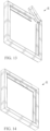
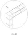
- FIGS. 11-13 Illustrated in FIGS. 11-13 are left and right disassembled perspective views of a spacer frame assembly constructed in accordance with one example embodiment of the present disclosure. Illustrated in FIGS. 14-22 is a spacer frame assembly constructed in accordance with another example embodiment of the present disclosure.
- the opposite frame end 54 of segment 30d is substantially orthangonal ( see angle ⁇ ) about the lateral axis "LA" of the segment.
- the positive stop 64 of the tucking member 34 reassures that the aperture alignment between apertures 70 and 72 is perfectly concentric with each assembly.
- the final member 30d is swaged or narrowed along dimension "e" ( see FIGS. 4A and 4B ) during roll forming such that the tab 34 has a tighter fit when inserted into the channel formed in the final member and 54 ( see FIG. 10K ) when compared to conventional connections ( see FIG. 10J ).
- FIGS. 10E, 10F, and 10G Illustrated in FIGS. 10E, 10F, and 10G are three different example embodiments exemplifying unique final member 30d and 90 constructions and nose 62 constructions of the tab 34. These various constructions permit d'ifferent options for ease of assembly.
- the end 90 is chamfered or transverse about the lateral axis LA. While the end 90 could also be rounded as illustrated in FIG. 10F.
- FIGS. 10E and 10G illustrate a rounded nose 62 and a pointed nose, respectively.
- the nose 62 could also be orthogonal or blunted as illustrated in the example embodiment of FIG. 10F .
- failure in the spacer frame assembly 12 is further reduced by the identical construction of all four comers C1-C4 and the locating of the lateral connection 60 at a spaced distance ( see FIG. 7 ) from any of the four corners.
- failure is reduced because dimensions "a" and "b" are configurable dimensions that can be increased or decreased unlike conventional spacer frames in which the connection was located at a respective corner of the spacer frame ( see FIG. 1A-1E ).
- the connection location could not be varied or configurable because the location of the web or stamp lines define the fold and comer that must match the web or stamp lines in the other remaining corners in order to have a substantially orthogonal frame. Therefore, any run-out existed in the corner connection of the conventional spacer frame, making such connection less robust.
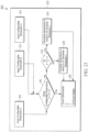
- FIG. 23 Illustrated in FIG. 23 is a flow diagram, illustrating a method 200 for constructing a spacer frame assembly 12 having configurable dimensions "a", “b” and “c” ( see FIG. 7 ) 210, 212, 214, respectively in accordance with one example embodiment of the present disclosure.
- the configurable dimensions a, b, and c 210, 212, and 214 are controlled by a CPU or computer 220 in, for example the computer's hardware, software, firmware, and the like. Altering any of the configurable dimensions 210, 212, and 214 does not influence or change the construction of the corner structures 32.
- the method 200 receives the values of configurable dimensions for a, b, and c at 210, 212, and 214, respectively.
- step 216 determines whether or not the sum of configurable dimensions a 210 and b 212 is equal to configurable dimension c 214. If the determination of step 216 is an affirmative, step 218 occurs in which the flat stock from a continuous coil 48 is advanced to a punch station (not shown) and configurable dimensions a 210, b 212, and c 214 are formed by punching dies to generate the punch strip 36 illustrated in FIG. 4A . ,
- step 216 determines whether configurable dimensions a 210 plus b 212 is greater than configurable dimension c. If the determination at step 222 is an affirmative, step 224 occurs in which configurable dimensions a 210 and/or b 212 is decreased or configurable dimension c is increased. After the changes to the configurable dimensions occurs at 224, step 218 as previously described is performed. If the determination at step 222 Is negative, step 226 occurs in which configurable dimensions a 210 and/or b 212 is increased or configurable dimension c is decreased. After the changes to the configurable dimensions occurs at 226, step 218 as previously described is performed.
- spacer frame assembly 16 having only a four-sided assembled construction is shown with a lateral connection 60 spaced from a corner C is shown, it should be appreciated that other polygons of more or less sides having a lateral connection is intended to be within the scope of the present claims and disclosure.
- the spacer frame assembly 16 further forms the union point 58 of the lateral connection 60 from a single integrally continuous punch strip 36 that is roll formed to form lateral walls 42, 44, peripheral wall 40, and stiffing flanges 46 throughout without the need for additional joiner clips.
Landscapes
- Engineering & Computer Science (AREA)
- Civil Engineering (AREA)
- Structural Engineering (AREA)
- Architecture (AREA)
- Physics & Mathematics (AREA)
- Electromagnetism (AREA)
- Life Sciences & Earth Sciences (AREA)
- Wood Science & Technology (AREA)
- Securing Of Glass Panes Or The Like (AREA)
- Escalators And Moving Walkways (AREA)
Claims (23)
- Eine Abstandhalterrahmenanordnung (12) zum Biegen in einen mehrseitigen Fenster- oder Türabstandhalterrahmen, wobei die Anordnung umfasst:einen im Wesentlichen geradlinigen Kanal mit einem ersten und einem zweiten Ende, wobei der im Wesentlichen geradlinige Kanal, wenn sich der Abstandhalterrahmen in der zusammengebauten Position befindet, wenigstens drei Seiten (30) und entsprechende Ecken (32) zwischen jeder der Seiten (30) aufweist;eine Verbindungsstruktur (34), die an einem der ersten und zweiten Enden (54, 56) angeordnet ist, und ein gegenüberliegendes Rahmenende (54), das an dem anderen der ersten und zweiten Enden (54, 56) angeordnet ist, wobei die Verbindungsstruktur (34) und das gegenüberliegende Rahmenende (54) eine Umfangswand (40) umfassen, die eine erste und zweite Seitenwand (42, 44) quer beabstandet, um einen u-förmigen Kanal zu bilden, wobei das gegenüberliegende Rahmenende (54) einen inneren Kanal zur teleskopischen Aufnahme einer Nase (62) der Verbindungsstruktur (34) aufweist; undeinen Anschlag (64), der sich von der Verbindungsstruktur (34) erstreckt, um das gegenüberliegende Rahmenende (54) in der zusammengebauten Position des Abstandhalterrahmens anzuordnen;wobei der Abstandhalterrahmen in der zusammengebauten Position eine Seitenverbindung (60) aufweist, die von den entsprechenden Ecken (32) und entlang einer der wenigstens drei Seiten (30) beabstandet ist, wobei die Seitenverbindung (60) einen Verbindungspunkt (58) durch den Anschlag zwischen dem gegenüberliegenden Rahmenende (54) und der Verbindungsstruktur (34) bildet.
- Abstandhalterrahmenanordnung (12) nach Anspruch 1, wobei der Anschlag (64) einen ersten und einen zweiten Versteifungsflansch (46) aufweist, die an dem gegenüberliegenden Rahmenende (54) anliegen, um den Verbindungspunkt (58) zu bilden, wobei der Verbindungspunkt (58) über wiederholtes Zusammenbauen der Abstandhalterrahmenanordnung (12) anordenbar ist.
- Abstandhalterrahmenanordnung (12) nach Anspruch 1, bei der von der ersten und der zweiten Seitenwand (42, 44) jeweils ein Versteifungsflansch (46) vorsteht, wobei der Versteifungsflansch (46) in der Verbindungsstruktur (34) als der Anschlag (64) wirkt, um mit dem Versteifungsflansch (46) in dem gegenüberliegenden Rahmenende (54) in Eingriff zu kommen.
- Die Abstandhalterrahmenanordnung (12) nach Anspruch 2 oder Anspruch 3, wobei:Versteifungsflansche (46) quer von den Seitenwänden (42, 44) der Verbindungsstruktur (34) vorstehen; undVersteifungsflansche (46) quer von der ersten Seitenwand (42) und der zweiten Seitenwand (44) des gegenüberliegenden Rahmenendes (54) vorstehen,die Versteifungsflansche (46) im Wesentlichen parallel zu der Umfangswand (40) verlaufen.
- Abstandhalterrahmenanordnung (12) nach einem der Ansprüche 1 bis 4, wobei die Ecken (32), die die wenigstens drei Seiten (30) verbinden, identisch ausgebildet sind, wenn sich die Abstandhalterrahmenanordnung (12) in ihrer vollständig zusammengebauten Position befindet.
- Die Abstandhalterrahmenanordnung (12) nach einem der Ansprüche 1 bis 5, wobei die Verbindungsstruktur (34) und das gegenüberliegende Rahmenende (54) jeweils eine Öffnung (70, 72) zur Aufnahme eines Befestigungsmittels aufweisen, wobei die Öffnungen (70, 72) im Wesentlichen konzentrisch ausgerichtet sind, wenn das gegenüberliegende Rahmenende (54) mit dem Anschlag (64) zusammenwirkt, der sich an der Verbindungsstruktur (34) in der zusammengebauten Position des Abstandhalterrahmens befindet.
- Die Abstandhalterrahmenanordnung (12) nach Anspruch 1 oder Anspruch 2, wobei jede der wenigstens drei Seiten (30) ferner eine Umfangswand (40) aufweist, die eine erste und eine zweite Seitenwand (42, 44) quer beabstandet, um einen u-förmigen Kanal zu bilden, wobei
von der ersten und zweiten Seitenwand (42, 44) jeweils ein beabstandeter Versteifungsflansch (46) vorsteht. - Die Abstandhalterrahmenbaugruppe (12) nach einem der Ansprüche 1 bis 7, wobei einer der Verbindungsstruktur und des gegenüberliegenden Rahmenendes einen sich verjüngenden gestauchten Abschnitt zur Aufnahme des jeweils anderen der Verbindungsstruktur und des gegenüberliegenden Rahmenendes aufweist.
- Abstandhalterrahmenanordnung (12) nach einem der Ansprüche 1 bis 8, wobei die Nase (62) der Verbindungsstruktur (34) aus einem Nasenabschnitt (34) mit einer sich verjüngenden Form gebildet ist, sodass, wenn die Nase (62) in das gegenüberliegende Rahmenende (54) eingeführt wird, eine teleskopische Seitenverbindung (60) mit abnehmendem Spiel bis hin zu einer Presspassung in der zusammengebauten Position des Abstandhalterrahmens gebildet wird.
- Abstandhalterrahmenanordnung (12) nach einem der Ansprüche 1 bis 9, wobei die Nase (62) der Verbindungsstruktur (34) ferner eine sich verjüngende Breite aufweist, so dass, wenn die Nase (62) in das gegenüberliegende Rahmenende (54) eingeführt wird, eine teleskopische Seitenverbindung (60) mit abnehmendem Spiel bis hin zu einer Presspassung gebildet wird, und wobei die Nase (62) ferner ein schräges Profil aufweist, sodass das schräge Profil zum Zusammenbau unter den Versteifungsflanschen (46) des gegenüberliegenden Rahmenendes (54) bleibt.
- Abstandhalterrahmenanordnung (12) nach einem der Ansprüche 1 bis 10, wobei der Anschlag (64) einen physischen Anschlag (64) umfasst, der von einer der Seitenwände (42, 44), die den geradlinigen Kanal bilden, und der Umfangswand (40) nach außen ragt.
- Verfahren zur Herstellung einer Abstandhalterrahmenanordnung (12) zum Biegen in einen mehrseitigen Fenster- oder Türabstandhalterrahmen, wobei das Verfahren umfasst:a) Bereitstellen eines Vorrats an schmalem Metallstreifen (48), der auf einen Träger aufgewickelt ist;b) Abwickeln des Metallstreifens (48) von dem Träger, um einen länglichen Metallstreifen (48) bereitzustellen, und Bewegen des länglichen Metallstreifens (48) entlang einer Bewegungsbahn zu einer Stanzstation (104);c) Stanzen des Streifens (48) an wenigstens drei voneinander beabstandeten Eckstellen durch Entfernen von Abschnitten des Streifens (48) an den Eckstellen, wobei ineinanderpassende vordere und hintere Enden der Abstandhalterrahmenanordnung (12) durch einen vorderen Abschnitt des Streifens (48), der sich vor einer ersten Eckstelle (32a) erstreckt, und einen hinteren Abschnitt des Streifens (48), der sich hinter einer zweiten Eckstelle (32d) erstreckt, definiert sind;d) zusätzliches Stanzen von wenigstens einem der vorderen und hinteren Abschnitte des Streifens (48), um einen Anschlag (64) zu bilden, der einen breiten Abschnitt des Streifens (48) und eine Nase (62) aufweist, die sich in den breiten Abschnitt des Streifens (48) erstreckt, um ein Ausmaß der Überlappung der vorderen und hinteren Enden in einem zusammengebauten Abstandshalterrahmen zu definieren;e) Walzprofilieren des Streifens (48) zur Bildung einer kanalförmigen Struktur mit Seitenwänden (42, 44), die den Anschlag (64) und eine sich zwischen den Seitenwänden (42, 44) erstreckende Bodenwand (40) enthalten; undf) Abtrennen der Rahmenanordnung (12) von dem länglichen Metallstreifen (48);wobei der zusammengebaute Abstandhalterrahmen eine Seitenverbindung (60) aufweist, die von den Ecken (32) und entlang einer von wenigstens drei Seiten (30) beabstandet ist, wobei die Seitenverbindung (60) einen Verbindungspunkt (58) durch den Anschlag bildet.
- Verfahren nach Anspruch 12 zusätzlich umfassend ein Aufbringen eines Dichtmittels (18) auf die Außenflächen der Seiten- und Bodenwände (40, 42, 44) der Abstandhalterrahmenanordnung (12) nach dem Abtrennen der Rahmenanordnung (12) von dem länglichen Metallstreifen (48).
- Verfahren nach Anspruch 12 oder 13, wobei der Abtrennschritt ein anstoßendes Ende der Abstandshalterrahmenanordnung (12) bildet.
- Verfahren nach einem der Ansprüche 12 bis 14, wobei das Walzprofilieren des Streifens (48) ein Ausbilden von Versteifungsflanschen (46) entlang der Seitenwände (42, 44) umfasst.
- Verfahren nach einem der Ansprüche 12 bis 15, wobei die Überlappung einen Überlappungsabstand umfasst, der geringer ist als ein Abstand zwischen dem Anschlag (64) und der ersten Eckstelle (32a) und der zweiten Eckstelle (32d), und wobei die Überlappung ferner geringer ist als ein Abstand zwischen der Nase (62) und der ersten Eckstelle (32a) und der zweiten Eckstelle (32d) in dem zusammengebauten Zustand.
- Verfahren nach Anspruch 16, wobei das Ausbilden von Versteifungsflanschen (46) ein Ausbilden der Versteifungsflansche (46) im Wesentlichen parallel zur Basiswand (40) umfasst.
- Verfahren nach Anspruch 15 oder Anspruch 17, wobei Versteifungsflansche (46) am vorderen Ende, das den Anschlag (64) umfasst, an Versteifungsflanschen (46) am hinteren Ende der Abstandhalterrahmenanordnung (12) an einer Stelle anliegen, die von der ersten Eckstelle (32a) und der zweiten Eckstelle (32d) beabstandet ist, wenn sie in Gebrauch ist.
- Verfahren nach einem der Ansprüche 12 bis 18, wobei das Ausbilden des Anschlags (64) das Definieren einer Kerbe umfasst, die sich von den Seitenwänden (42, 44) in die kanalförmige Struktur hinein erstreckt, sich quer zu den Seitenwänden (42, 44) aus der kanalförmigen Struktur heraus erstreckt und/oder sich quer zur Basiswand (40) aus der kanalförmigen Struktur heraus erstreckt.
- Verfahren nach Anspruch 19, wobei das Definieren einer Kerbe ein Ausbilden der Kerbe auf der Nase (62) im Abstand von der ersten Eckstelle (32a) oder der zweiten Eckstelle (32d) umfasst.
- Verfahren nach einem der Ansprüche 12 bis 20, wobei ein anstoßendes Ende der Abstandhalterrahmenanordnung (12), das sich am vorderen Ende oder am hinteren Ende der Abstandhalterrahmenanordnung (12) befindet, dazu ausgebildet ist, an einer Anschlagstelle mit dem Anschlag (64) zusammenzuwirken, der Anschlag (64) an einem gegenüberliegenden Ende der Abstandhalterrahmenanordnung (12) relativ zu dem anstoßenden Ende angeordnet ist, wobei die Anschlagstelle im Gebrauch von der ersten Eckstelle (32a) und der zweiten Eckstelle (32d) beabstandet ist, und wobei die Anschlagstelle über wiederholtes Zusammenbauen des zusammengebauten Abstandhalterrahmens anordenbar ist.
- Verfahren nach einem der Ansprüche 12 bis 21, wobei das Stanzen des Streifens (48) ein Ausbilden einer ersten Öffnung (70) am vorderen Ende und einer zweiten Öffnung (72) am hinteren Ende umfasst, wobei die erste und die zweite Öffnung (70, 72) zur Aufnahme eines Befestigungsmittels im Wesentlichen konzentrisch ausgerichtet sind, wenn das vordere Ende und das hintere Ende an der Anschlagstelle zusammenwirken.
- Verfahren nach einem der Ansprüche 12 bis 22, ferner umfassend ein Biegen des Streifens (48) an den Eckstellen, um drei oder mehr Ecken (32) zu bilden, wobei die drei oder mehr Ecken (32), die drei oder mehr Seiten (30) verbinden, identisch aufgebaut sind, wenn sich die Abstandhalterrahmenanordnung (12) in einer vollständig zusammengebauten Position befindet.
Applications Claiming Priority (3)
| Application Number | Priority Date | Filing Date | Title |
|---|---|---|---|
| US201462011253P | 2014-06-12 | 2014-06-12 | |
| US14/703,027 US9428953B2 (en) | 2014-06-12 | 2015-05-04 | Spacer frame and method of making same |
| PCT/US2015/030310 WO2015191205A1 (en) | 2014-06-12 | 2015-05-12 | Spacer frame and method of making same |
Publications (3)
| Publication Number | Publication Date |
|---|---|
| EP3155200A1 EP3155200A1 (de) | 2017-04-19 |
| EP3155200A4 EP3155200A4 (de) | 2018-01-24 |
| EP3155200B1 true EP3155200B1 (de) | 2023-07-19 |
Family
ID=54834081
Family Applications (1)
| Application Number | Title | Priority Date | Filing Date |
|---|---|---|---|
| EP15806949.2A Active EP3155200B1 (de) | 2014-06-12 | 2015-05-12 | Abstandhalterrahmen und verfahren zur herstellung davon |
Country Status (7)
| Country | Link |
|---|---|
| US (4) | US9428953B2 (de) |
| EP (1) | EP3155200B1 (de) |
| CA (1) | CA2950407C (de) |
| ES (1) | ES2959513T3 (de) |
| PL (1) | PL3155200T3 (de) |
| RU (1) | RU2692886C2 (de) |
| WO (1) | WO2015191205A1 (de) |
Families Citing this family (16)
| Publication number | Priority date | Publication date | Assignee | Title |
|---|---|---|---|---|
| US9428953B2 (en) | 2014-06-12 | 2016-08-30 | Ged Integrated Solutions, Inc. | Spacer frame and method of making same |
| US20160258205A1 (en) | 2015-03-03 | 2016-09-08 | Andersen Corporation | Offset seam for insulating glass unit spacer and method of using and manufacturing the same |
| USD1058859S1 (en) | 2015-05-04 | 2025-01-21 | Ged Integrated Solutions, Inc. | Spacer frame |
| US10352090B2 (en) * | 2015-09-15 | 2019-07-16 | Ged Integrated Solutions, Inc. | Window spacer frame punch assembly |
| US10184290B2 (en) * | 2015-09-15 | 2019-01-22 | Ged Integrated Solutions, Inc. | Window spacer frame crimping assembly |
| USD824747S1 (en) * | 2016-09-30 | 2018-08-07 | Ged Integrated Solutions, Inc. | Window spacer frame locking member |
| ES2946995T3 (es) * | 2016-09-30 | 2023-07-31 | Ged Integrated Solutions Inc | Conjunto de marco separador |
| US10920480B2 (en) | 2017-09-05 | 2021-02-16 | Ged Integrated Solutions, Inc. | Thermally efficient window frame |
| US10107027B1 (en) | 2017-10-24 | 2018-10-23 | Quaker Window Products Co. | Thermally enhanced multi-component window |
| US10947772B2 (en) | 2017-10-24 | 2021-03-16 | Quaker Window Products Co. | Thermally enhanced multi-component glass doors and windows |
| US10828121B2 (en) | 2018-03-22 | 2020-11-10 | Alcon Inc. | Composite frame system |
| US11859439B2 (en) * | 2020-04-15 | 2024-01-02 | Vitro Flat Glass Llc | Low thermal conducting spacer assembly for an insulating glazing unit |
| WO2022040298A1 (en) * | 2020-08-18 | 2022-02-24 | Ged Integrated Solutions, Inc. | Improved spacer frame with rising locking member |
| US12258810B2 (en) | 2020-09-28 | 2025-03-25 | Vitro Flat Glass Llc | Device for distributing sealant materials and methods of using the same |
| USD1095892S1 (en) * | 2024-01-19 | 2025-09-30 | Cascade Ohio, Inc. | Column trim |
| USD1079062S1 (en) * | 2024-01-30 | 2025-06-10 | Cascade Ohio, Inc. | Column mounting plate |
Family Cites Families (31)
| Publication number | Priority date | Publication date | Assignee | Title |
|---|---|---|---|---|
| US4222209A (en) | 1978-02-27 | 1980-09-16 | Peterson Metal Products, Ltd. | Cornerpiece for use in multiple pane window |
| US4513546A (en) * | 1980-03-12 | 1985-04-30 | Norton Company | Corner key for window spacer element |
| US4628582A (en) | 1981-12-04 | 1986-12-16 | Glass Equipment Development, Inc. | Method of making spacer frame for an insulating glass panel |
| US5105591A (en) | 1980-04-03 | 1992-04-21 | Glass Equipment Development, Inc. | Spacer frame for an insulating glass panel and method of making the same |
| CA1294824C (en) | 1987-01-21 | 1992-01-28 | Gunter Berdan | Fold-up corner piece for spacer tube assembly |
| US5177916A (en) | 1990-09-04 | 1993-01-12 | Ppg Industries, Inc. | Spacer and spacer frame for an insulating glazing unit and method of making same |
| US5313761A (en) * | 1992-01-29 | 1994-05-24 | Glass Equipment Development, Inc. | Insulating glass unit |
| US5439716A (en) | 1992-03-19 | 1995-08-08 | Cardinal Ig Company | Multiple pane insulating glass unit with insulative spacer |
| US5295292A (en) | 1992-08-13 | 1994-03-22 | Glass Equipment Development, Inc. | Method of making a spacer frame assembly |
| US5531047A (en) * | 1993-08-05 | 1996-07-02 | Ppg Industries, Inc. | Glazing unit having three or more glass sheets and having a low thermal edge, and method of making same |
| US5644894A (en) * | 1994-10-20 | 1997-07-08 | Ppg Industries, Inc. | Multi-sheet glazing unit and method of making same |
| US5813191A (en) | 1996-08-29 | 1998-09-29 | Ppg Industries, Inc. | Spacer frame for an insulating unit having strengthened sidewalls to resist torsional twist |
| US7021110B2 (en) | 2003-05-23 | 2006-04-04 | Ppg Industries Ohio, Inc. | Apparatus for preparing U-shaped spacers for insulating units |
| US7827761B2 (en) | 2003-06-23 | 2010-11-09 | Ppg Industries Ohio, Inc. | Plastic spacer stock, plastic spacer frame and multi-sheet unit, and method of making same |
| US7739851B2 (en) | 2003-06-23 | 2010-06-22 | Ppg Industries Ohio, Inc. | Plastic spacer stock, plastic spacer frame and multi-sheet unit, and method of making same |
| US7950194B2 (en) * | 2003-06-23 | 2011-05-31 | Ppg Industries Ohio, Inc. | Plastic spacer stock, plastic spacer frame and multi-sheet unit, and method of making same |
| US7856791B2 (en) | 2003-06-23 | 2010-12-28 | Ppg Industries Ohio, Inc. | Plastic spacer stock, plastic spacer frame and multi-sheet unit, and method of making same |
| DE102004027527A1 (de) * | 2004-02-03 | 2005-08-18 | Karl Lenhardt | Verfahren zum Herstellen einer Isolierglasscheibe |
| WO2005075783A1 (de) | 2004-02-03 | 2005-08-18 | Karl Lenhardt | Isolierglasscheibe und verfahren zu ihrer herstellung |
| US7802365B2 (en) | 2004-09-29 | 2010-09-28 | Ged Integrated Solutions, Inc. | Window component scrap reduction |
| US7866033B2 (en) | 2004-09-29 | 2011-01-11 | Ged Integrated Solutions, Inc. | Window component system including pusher for scrap removal |
| US7610681B2 (en) * | 2004-09-29 | 2009-11-03 | Ged Integrated Solutions, Inc. | Window component stock indexing |
| US7448246B2 (en) | 2006-05-02 | 2008-11-11 | Ged Integrated Solutions, Inc. | Window frame corner fabrication |
| US8001742B2 (en) | 2006-08-16 | 2011-08-23 | Ged Integrated Solutions, Inc. | Muntin bar clip and muntin bar assembly |
| US8057120B2 (en) | 2006-09-07 | 2011-11-15 | Andersen Corporation | Corner joining of structural members |
| CA2720758A1 (en) | 2008-04-11 | 2009-10-15 | Plus Inventia Ag | Method for producing a corner of a frame-shaped spacer for insulating glass panes and spacer and insulating glass panes produced according the method |
| US8652382B2 (en) | 2008-07-01 | 2014-02-18 | Andersen Corporation | Methods of joining |
| US20120137608A1 (en) | 2010-09-13 | 2012-06-07 | Billco Manufacturing Incorporated | Flexible wrapped insulated glass unit spacer, system and method for manufacturing same in situ and an insulated glass unit having a flexible wrapped spacer |
| US8851787B2 (en) | 2011-08-23 | 2014-10-07 | Andersen Corporation | Corner joint and method of manufacturing |
| US9765564B2 (en) | 2013-03-14 | 2017-09-19 | Ged Integrated Solutions, Inc. | Automated spacer frame fabrication and method |
| US9428953B2 (en) | 2014-06-12 | 2016-08-30 | Ged Integrated Solutions, Inc. | Spacer frame and method of making same |
-
2015
- 2015-05-04 US US14/703,027 patent/US9428953B2/en active Active
- 2015-05-12 PL PL15806949.2T patent/PL3155200T3/pl unknown
- 2015-05-12 EP EP15806949.2A patent/EP3155200B1/de active Active
- 2015-05-12 CA CA2950407A patent/CA2950407C/en active Active
- 2015-05-12 WO PCT/US2015/030310 patent/WO2015191205A1/en not_active Ceased
- 2015-05-12 RU RU2017100466A patent/RU2692886C2/ru active
- 2015-05-12 ES ES15806949T patent/ES2959513T3/es active Active
-
2016
- 2016-08-01 US US15/224,783 patent/US10316578B2/en active Active
-
2017
- 2017-11-08 US US15/806,962 patent/US10533367B2/en active Active
-
2019
- 2019-12-18 US US16/719,120 patent/US11028638B2/en active Active
Also Published As
| Publication number | Publication date |
|---|---|
| US10316578B2 (en) | 2019-06-11 |
| RU2692886C2 (ru) | 2019-06-28 |
| US20160340962A1 (en) | 2016-11-24 |
| ES2959513T3 (es) | 2024-02-26 |
| WO2015191205A1 (en) | 2015-12-17 |
| EP3155200A1 (de) | 2017-04-19 |
| US20150361713A1 (en) | 2015-12-17 |
| US20200224487A1 (en) | 2020-07-16 |
| US10533367B2 (en) | 2020-01-14 |
| US11028638B2 (en) | 2021-06-08 |
| EP3155200A4 (de) | 2018-01-24 |
| PL3155200T3 (pl) | 2024-02-26 |
| US20180066472A1 (en) | 2018-03-08 |
| CA2950407C (en) | 2019-03-12 |
| CA2950407A1 (en) | 2015-12-17 |
| US9428953B2 (en) | 2016-08-30 |
Similar Documents
| Publication | Publication Date | Title |
|---|---|---|
| US11028638B2 (en) | Spacer frame and method of making same | |
| EP3519658B1 (de) | Abstandshalterrahmenanordnung | |
| US10352090B2 (en) | Window spacer frame punch assembly | |
| US6360420B2 (en) | Insulated glass window spacer and method for making window spacer | |
| CA2169498C (en) | Spacer for an insulated window panel assembly | |
| US20120137608A1 (en) | Flexible wrapped insulated glass unit spacer, system and method for manufacturing same in situ and an insulated glass unit having a flexible wrapped spacer | |
| US8769889B2 (en) | Spacer for insulating glass panes | |
| US20220127900A1 (en) | Spacer frame joiner clip and method of use | |
| US20180135348A1 (en) | Offset seam for insulating glass unit spacer and method of using and manufacturing the same | |
| US12134931B2 (en) | Spacer frame with rising locking member | |
| CA2639201A1 (en) | Plug connector for retaining hollow sections | |
| US8104238B2 (en) | Window spacer and corner-fastening concept |
Legal Events
| Date | Code | Title | Description |
|---|---|---|---|
| STAA | Information on the status of an ep patent application or granted ep patent |
Free format text: STATUS: THE INTERNATIONAL PUBLICATION HAS BEEN MADE |
|
| PUAI | Public reference made under article 153(3) epc to a published international application that has entered the european phase |
Free format text: ORIGINAL CODE: 0009012 |
|
| STAA | Information on the status of an ep patent application or granted ep patent |
Free format text: STATUS: REQUEST FOR EXAMINATION WAS MADE |
|
| 17P | Request for examination filed |
Effective date: 20161213 |
|
| AK | Designated contracting states |
Kind code of ref document: A1 Designated state(s): AL AT BE BG CH CY CZ DE DK EE ES FI FR GB GR HR HU IE IS IT LI LT LU LV MC MK MT NL NO PL PT RO RS SE SI SK SM TR |
|
| AX | Request for extension of the european patent |
Extension state: BA ME |
|
| DAV | Request for validation of the european patent (deleted) | ||
| DAX | Request for extension of the european patent (deleted) | ||
| A4 | Supplementary search report drawn up and despatched |
Effective date: 20171222 |
|
| RIC1 | Information provided on ipc code assigned before grant |
Ipc: E06B 3/673 20060101AFI20171218BHEP |
|
| STAA | Information on the status of an ep patent application or granted ep patent |
Free format text: STATUS: EXAMINATION IS IN PROGRESS |
|
| 17Q | First examination report despatched |
Effective date: 20180814 |
|
| GRAP | Despatch of communication of intention to grant a patent |
Free format text: ORIGINAL CODE: EPIDOSNIGR1 |
|
| STAA | Information on the status of an ep patent application or granted ep patent |
Free format text: STATUS: GRANT OF PATENT IS INTENDED |
|
| INTG | Intention to grant announced |
Effective date: 20230208 |
|
| GRAS | Grant fee paid |
Free format text: ORIGINAL CODE: EPIDOSNIGR3 |
|
| GRAA | (expected) grant |
Free format text: ORIGINAL CODE: 0009210 |
|
| STAA | Information on the status of an ep patent application or granted ep patent |
Free format text: STATUS: THE PATENT HAS BEEN GRANTED |
|
| P01 | Opt-out of the competence of the unified patent court (upc) registered |
Effective date: 20230525 |
|
| AK | Designated contracting states |
Kind code of ref document: B1 Designated state(s): AL AT BE BG CH CY CZ DE DK EE ES FI FR GB GR HR HU IE IS IT LI LT LU LV MC MK MT NL NO PL PT RO RS SE SI SK SM TR |
|
| REG | Reference to a national code |
Ref country code: GB Ref legal event code: FG4D |
|
| REG | Reference to a national code |
Ref country code: CH Ref legal event code: EP |
|
| REG | Reference to a national code |
Ref country code: DE Ref legal event code: R096 Ref document number: 602015084675 Country of ref document: DE |
|
| REG | Reference to a national code |
Ref country code: IE Ref legal event code: FG4D |
|
| REG | Reference to a national code |
Ref country code: DE Ref legal event code: R081 Ref document number: 602015084675 Country of ref document: DE Owner name: GED INTEGRATED SOLUTIONS, INC., GLENWILLOW, US Free format text: FORMER OWNER: GED INTEGRATED SOLUTIONS, INC., TWINSBURG, OH, US |
|
| REG | Reference to a national code |
Ref country code: LT Ref legal event code: MG9D |
|
| REG | Reference to a national code |
Ref country code: NL Ref legal event code: MP Effective date: 20230719 |
|
| REG | Reference to a national code |
Ref country code: AT Ref legal event code: MK05 Ref document number: 1589655 Country of ref document: AT Kind code of ref document: T Effective date: 20230719 |
|
| PG25 | Lapsed in a contracting state [announced via postgrant information from national office to epo] |
Ref country code: NL Free format text: LAPSE BECAUSE OF FAILURE TO SUBMIT A TRANSLATION OF THE DESCRIPTION OR TO PAY THE FEE WITHIN THE PRESCRIBED TIME-LIMIT Effective date: 20230719 |
|
| PG25 | Lapsed in a contracting state [announced via postgrant information from national office to epo] |
Ref country code: GR Free format text: LAPSE BECAUSE OF FAILURE TO SUBMIT A TRANSLATION OF THE DESCRIPTION OR TO PAY THE FEE WITHIN THE PRESCRIBED TIME-LIMIT Effective date: 20231020 |
|
| PG25 | Lapsed in a contracting state [announced via postgrant information from national office to epo] |
Ref country code: IS Free format text: LAPSE BECAUSE OF FAILURE TO SUBMIT A TRANSLATION OF THE DESCRIPTION OR TO PAY THE FEE WITHIN THE PRESCRIBED TIME-LIMIT Effective date: 20231119 |
|
| PG25 | Lapsed in a contracting state [announced via postgrant information from national office to epo] |
Ref country code: SE Free format text: LAPSE BECAUSE OF FAILURE TO SUBMIT A TRANSLATION OF THE DESCRIPTION OR TO PAY THE FEE WITHIN THE PRESCRIBED TIME-LIMIT Effective date: 20230719 Ref country code: RS Free format text: LAPSE BECAUSE OF FAILURE TO SUBMIT A TRANSLATION OF THE DESCRIPTION OR TO PAY THE FEE WITHIN THE PRESCRIBED TIME-LIMIT Effective date: 20230719 Ref country code: PT Free format text: LAPSE BECAUSE OF FAILURE TO SUBMIT A TRANSLATION OF THE DESCRIPTION OR TO PAY THE FEE WITHIN THE PRESCRIBED TIME-LIMIT Effective date: 20231120 Ref country code: NO Free format text: LAPSE BECAUSE OF FAILURE TO SUBMIT A TRANSLATION OF THE DESCRIPTION OR TO PAY THE FEE WITHIN THE PRESCRIBED TIME-LIMIT Effective date: 20231019 Ref country code: LV Free format text: LAPSE BECAUSE OF FAILURE TO SUBMIT A TRANSLATION OF THE DESCRIPTION OR TO PAY THE FEE WITHIN THE PRESCRIBED TIME-LIMIT Effective date: 20230719 Ref country code: LT Free format text: LAPSE BECAUSE OF FAILURE TO SUBMIT A TRANSLATION OF THE DESCRIPTION OR TO PAY THE FEE WITHIN THE PRESCRIBED TIME-LIMIT Effective date: 20230719 Ref country code: IS Free format text: LAPSE BECAUSE OF FAILURE TO SUBMIT A TRANSLATION OF THE DESCRIPTION OR TO PAY THE FEE WITHIN THE PRESCRIBED TIME-LIMIT Effective date: 20231119 Ref country code: HR Free format text: LAPSE BECAUSE OF FAILURE TO SUBMIT A TRANSLATION OF THE DESCRIPTION OR TO PAY THE FEE WITHIN THE PRESCRIBED TIME-LIMIT Effective date: 20230719 Ref country code: GR Free format text: LAPSE BECAUSE OF FAILURE TO SUBMIT A TRANSLATION OF THE DESCRIPTION OR TO PAY THE FEE WITHIN THE PRESCRIBED TIME-LIMIT Effective date: 20231020 Ref country code: FI Free format text: LAPSE BECAUSE OF FAILURE TO SUBMIT A TRANSLATION OF THE DESCRIPTION OR TO PAY THE FEE WITHIN THE PRESCRIBED TIME-LIMIT Effective date: 20230719 Ref country code: AT Free format text: LAPSE BECAUSE OF FAILURE TO SUBMIT A TRANSLATION OF THE DESCRIPTION OR TO PAY THE FEE WITHIN THE PRESCRIBED TIME-LIMIT Effective date: 20230719 |
|
| REG | Reference to a national code |
Ref country code: ES Ref legal event code: FG2A Ref document number: 2959513 Country of ref document: ES Kind code of ref document: T3 Effective date: 20240226 |
|
| REG | Reference to a national code |
Ref country code: DE Ref legal event code: R097 Ref document number: 602015084675 Country of ref document: DE |
|
| PG25 | Lapsed in a contracting state [announced via postgrant information from national office to epo] |
Ref country code: SM Free format text: LAPSE BECAUSE OF FAILURE TO SUBMIT A TRANSLATION OF THE DESCRIPTION OR TO PAY THE FEE WITHIN THE PRESCRIBED TIME-LIMIT Effective date: 20230719 Ref country code: RO Free format text: LAPSE BECAUSE OF FAILURE TO SUBMIT A TRANSLATION OF THE DESCRIPTION OR TO PAY THE FEE WITHIN THE PRESCRIBED TIME-LIMIT Effective date: 20230719 Ref country code: EE Free format text: LAPSE BECAUSE OF FAILURE TO SUBMIT A TRANSLATION OF THE DESCRIPTION OR TO PAY THE FEE WITHIN THE PRESCRIBED TIME-LIMIT Effective date: 20230719 Ref country code: DK Free format text: LAPSE BECAUSE OF FAILURE TO SUBMIT A TRANSLATION OF THE DESCRIPTION OR TO PAY THE FEE WITHIN THE PRESCRIBED TIME-LIMIT Effective date: 20230719 Ref country code: CZ Free format text: LAPSE BECAUSE OF FAILURE TO SUBMIT A TRANSLATION OF THE DESCRIPTION OR TO PAY THE FEE WITHIN THE PRESCRIBED TIME-LIMIT Effective date: 20230719 Ref country code: SK Free format text: LAPSE BECAUSE OF FAILURE TO SUBMIT A TRANSLATION OF THE DESCRIPTION OR TO PAY THE FEE WITHIN THE PRESCRIBED TIME-LIMIT Effective date: 20230719 |
|
| PLBE | No opposition filed within time limit |
Free format text: ORIGINAL CODE: 0009261 |
|
| STAA | Information on the status of an ep patent application or granted ep patent |
Free format text: STATUS: NO OPPOSITION FILED WITHIN TIME LIMIT |
|
| 26N | No opposition filed |
Effective date: 20240422 |
|
| PG25 | Lapsed in a contracting state [announced via postgrant information from national office to epo] |
Ref country code: SI Free format text: LAPSE BECAUSE OF FAILURE TO SUBMIT A TRANSLATION OF THE DESCRIPTION OR TO PAY THE FEE WITHIN THE PRESCRIBED TIME-LIMIT Effective date: 20230719 |
|
| PG25 | Lapsed in a contracting state [announced via postgrant information from national office to epo] |
Ref country code: BG Free format text: LAPSE BECAUSE OF FAILURE TO SUBMIT A TRANSLATION OF THE DESCRIPTION OR TO PAY THE FEE WITHIN THE PRESCRIBED TIME-LIMIT Effective date: 20230719 |
|
| PG25 | Lapsed in a contracting state [announced via postgrant information from national office to epo] |
Ref country code: BG Free format text: LAPSE BECAUSE OF FAILURE TO SUBMIT A TRANSLATION OF THE DESCRIPTION OR TO PAY THE FEE WITHIN THE PRESCRIBED TIME-LIMIT Effective date: 20230719 |
|
| REG | Reference to a national code |
Ref country code: CH Ref legal event code: PL |
|
| PG25 | Lapsed in a contracting state [announced via postgrant information from national office to epo] |
Ref country code: MC Free format text: LAPSE BECAUSE OF FAILURE TO SUBMIT A TRANSLATION OF THE DESCRIPTION OR TO PAY THE FEE WITHIN THE PRESCRIBED TIME-LIMIT Effective date: 20230719 |
|
| PG25 | Lapsed in a contracting state [announced via postgrant information from national office to epo] |
Ref country code: LU Free format text: LAPSE BECAUSE OF NON-PAYMENT OF DUE FEES Effective date: 20240512 |
|
| PG25 | Lapsed in a contracting state [announced via postgrant information from national office to epo] |
Ref country code: MC Free format text: LAPSE BECAUSE OF FAILURE TO SUBMIT A TRANSLATION OF THE DESCRIPTION OR TO PAY THE FEE WITHIN THE PRESCRIBED TIME-LIMIT Effective date: 20230719 Ref country code: LU Free format text: LAPSE BECAUSE OF NON-PAYMENT OF DUE FEES Effective date: 20240512 Ref country code: CH Free format text: LAPSE BECAUSE OF NON-PAYMENT OF DUE FEES Effective date: 20240531 |
|
| REG | Reference to a national code |
Ref country code: BE Ref legal event code: MM Effective date: 20240531 |
|
| PG25 | Lapsed in a contracting state [announced via postgrant information from national office to epo] |
Ref country code: BE Free format text: LAPSE BECAUSE OF NON-PAYMENT OF DUE FEES Effective date: 20240531 |
|
| PGFP | Annual fee paid to national office [announced via postgrant information from national office to epo] |
Ref country code: DE Payment date: 20250529 Year of fee payment: 11 Ref country code: PL Payment date: 20250522 Year of fee payment: 11 |
|
| PGFP | Annual fee paid to national office [announced via postgrant information from national office to epo] |
Ref country code: ES Payment date: 20250602 Year of fee payment: 11 Ref country code: GB Payment date: 20250527 Year of fee payment: 11 |
|
| PGFP | Annual fee paid to national office [announced via postgrant information from national office to epo] |
Ref country code: IT Payment date: 20250521 Year of fee payment: 11 |
|
| PGFP | Annual fee paid to national office [announced via postgrant information from national office to epo] |
Ref country code: FR Payment date: 20250526 Year of fee payment: 11 |
|
| PGFP | Annual fee paid to national office [announced via postgrant information from national office to epo] |
Ref country code: IE Payment date: 20250527 Year of fee payment: 11 |
|
| PG25 | Lapsed in a contracting state [announced via postgrant information from national office to epo] |
Ref country code: CY Free format text: LAPSE BECAUSE OF FAILURE TO SUBMIT A TRANSLATION OF THE DESCRIPTION OR TO PAY THE FEE WITHIN THE PRESCRIBED TIME-LIMIT; INVALID AB INITIO Effective date: 20150512 |
|
| PG25 | Lapsed in a contracting state [announced via postgrant information from national office to epo] |
Ref country code: HU Free format text: LAPSE BECAUSE OF FAILURE TO SUBMIT A TRANSLATION OF THE DESCRIPTION OR TO PAY THE FEE WITHIN THE PRESCRIBED TIME-LIMIT; INVALID AB INITIO Effective date: 20150512 |