EP3154719B1 - A method of manufacture of vessels for pressurised fluids and apparatus thereof - Google Patents
A method of manufacture of vessels for pressurised fluids and apparatus thereof Download PDFInfo
- Publication number
- EP3154719B1 EP3154719B1 EP15728083.5A EP15728083A EP3154719B1 EP 3154719 B1 EP3154719 B1 EP 3154719B1 EP 15728083 A EP15728083 A EP 15728083A EP 3154719 B1 EP3154719 B1 EP 3154719B1
- Authority
- EP
- European Patent Office
- Prior art keywords
- ram
- closed
- pressure vessel
- curvature
- radius
- Prior art date
- Legal status (The legal status is an assumption and is not a legal conclusion. Google has not performed a legal analysis and makes no representation as to the accuracy of the status listed.)
- Active
Links
Images



Classifications
-
- F—MECHANICAL ENGINEERING; LIGHTING; HEATING; WEAPONS; BLASTING
- F17—STORING OR DISTRIBUTING GASES OR LIQUIDS
- F17C—VESSELS FOR CONTAINING OR STORING COMPRESSED, LIQUEFIED OR SOLIDIFIED GASES; FIXED-CAPACITY GAS-HOLDERS; FILLING VESSELS WITH, OR DISCHARGING FROM VESSELS, COMPRESSED, LIQUEFIED, OR SOLIDIFIED GASES
- F17C1/00—Pressure vessels, e.g. gas cylinder, gas tank, replaceable cartridge
-
- B—PERFORMING OPERATIONS; TRANSPORTING
- B21—MECHANICAL METAL-WORKING WITHOUT ESSENTIALLY REMOVING MATERIAL; PUNCHING METAL
- B21C—MANUFACTURE OF METAL SHEETS, WIRE, RODS, TUBES, PROFILES OR LIKE SEMI-MANUFACTURED PRODUCTS OTHERWISE THAN BY ROLLING; AUXILIARY OPERATIONS USED IN CONNECTION WITH METAL-WORKING WITHOUT ESSENTIALLY REMOVING MATERIAL
- B21C23/00—Extruding metal; Impact extrusion
- B21C23/02—Making uncoated products
- B21C23/20—Making uncoated products by backward extrusion
-
- B—PERFORMING OPERATIONS; TRANSPORTING
- B21—MECHANICAL METAL-WORKING WITHOUT ESSENTIALLY REMOVING MATERIAL; PUNCHING METAL
- B21C—MANUFACTURE OF METAL SHEETS, WIRE, RODS, TUBES, PROFILES OR LIKE SEMI-MANUFACTURED PRODUCTS OTHERWISE THAN BY ROLLING; AUXILIARY OPERATIONS USED IN CONNECTION WITH METAL-WORKING WITHOUT ESSENTIALLY REMOVING MATERIAL
- B21C23/00—Extruding metal; Impact extrusion
-
- B—PERFORMING OPERATIONS; TRANSPORTING
- B21—MECHANICAL METAL-WORKING WITHOUT ESSENTIALLY REMOVING MATERIAL; PUNCHING METAL
- B21C—MANUFACTURE OF METAL SHEETS, WIRE, RODS, TUBES, PROFILES OR LIKE SEMI-MANUFACTURED PRODUCTS OTHERWISE THAN BY ROLLING; AUXILIARY OPERATIONS USED IN CONNECTION WITH METAL-WORKING WITHOUT ESSENTIALLY REMOVING MATERIAL
- B21C23/00—Extruding metal; Impact extrusion
- B21C23/22—Making metal-coated products; Making products from two or more metals
-
- F—MECHANICAL ENGINEERING; LIGHTING; HEATING; WEAPONS; BLASTING
- F17—STORING OR DISTRIBUTING GASES OR LIQUIDS
- F17C—VESSELS FOR CONTAINING OR STORING COMPRESSED, LIQUEFIED OR SOLIDIFIED GASES; FIXED-CAPACITY GAS-HOLDERS; FILLING VESSELS WITH, OR DISCHARGING FROM VESSELS, COMPRESSED, LIQUEFIED, OR SOLIDIFIED GASES
- F17C2201/00—Vessel construction, in particular geometry, arrangement or size
- F17C2201/01—Shape
- F17C2201/0104—Shape cylindrical
- F17C2201/0114—Shape cylindrical with interiorly curved end-piece
-
- F—MECHANICAL ENGINEERING; LIGHTING; HEATING; WEAPONS; BLASTING
- F17—STORING OR DISTRIBUTING GASES OR LIQUIDS
- F17C—VESSELS FOR CONTAINING OR STORING COMPRESSED, LIQUEFIED OR SOLIDIFIED GASES; FIXED-CAPACITY GAS-HOLDERS; FILLING VESSELS WITH, OR DISCHARGING FROM VESSELS, COMPRESSED, LIQUEFIED, OR SOLIDIFIED GASES
- F17C2203/00—Vessel construction, in particular walls or details thereof
- F17C2203/06—Materials for walls or layers thereof; Properties or structures of walls or their materials
- F17C2203/0602—Wall structures; Special features thereof
- F17C2203/0612—Wall structures
- F17C2203/0614—Single wall
- F17C2203/0617—Single wall with one layer
-
- F—MECHANICAL ENGINEERING; LIGHTING; HEATING; WEAPONS; BLASTING
- F17—STORING OR DISTRIBUTING GASES OR LIQUIDS
- F17C—VESSELS FOR CONTAINING OR STORING COMPRESSED, LIQUEFIED OR SOLIDIFIED GASES; FIXED-CAPACITY GAS-HOLDERS; FILLING VESSELS WITH, OR DISCHARGING FROM VESSELS, COMPRESSED, LIQUEFIED, OR SOLIDIFIED GASES
- F17C2209/00—Vessel construction, in particular methods of manufacturing
- F17C2209/21—Shaping processes
- F17C2209/2181—Metal working processes, e.g. deep drawing, stamping or cutting
Definitions
- the present invention relates to a method of manufacture of vessels adapted to contain pressurised fluids, the manufacturing apparatus thereof and pressure vessels manufactured using this method. More particularly, the present invention concerns a backward extrusion method for the manufacture of metallic vessels capable of containing fluids under pressure, the extrusion apparatus thereof and pressure vessels manufactured according to that method. In particular, but not exclusively, the present invention relates to apparatus and a manufacturing method for closed-ended hoop wrap gas cylinders adapted to contain gases at pressures above atmospheric pressure and to the closed-ended hoop wrap gas cylinders produced by the method.
- Type I pressure vessels are manufactured in aluminium, steel and composite materials.
- Type II pressure vessels comprise a metallic vessel (usually made of aluminium) which has a filamentous composite sleeve, formed for example of an epoxy resin, aramid and/or carbon fiber, surrounding the cylindrical side wall only of the vessel (referred to herein as hoop wrap).
- Type II pressure vessels are generally lighter in weight than Type I pressure vessels because the metallic vessel wall of a Type II pressure vessel can be thinner than a Type I pressure vessel without loss of performance.
- repeated dispensing and vessel re-filling of gas under pressure causes the vessel to flex and such flexing can encourage the propagation of cracks in the vessel wall.
- autofrettage has been used to improve pressure vessel fatigue resistance.
- Autofrettage involves applying a pressure within the bore of the vessel sufficient to plastically deform the metal at the inner surface. The technique produces compressive residual stresses at or near the internal surface, and this enhances the fatigue resistance of the vessel subjected to cyclic internal pressure loading.
- WO96/11759 on which the preamble of the independent claims 1, 7 and 9 is based, describes the use of autofrettage in the manufacture of pressure vessels to cause regions of peak stress in the pressure vessel wall to move away from an internal or external wall surface.
- the present invention seeks to provide a pressure vessel manufacturing method, manufacturing apparatus and pressure vessels manufactured using the method which improves the pressure vessel's resistance to fatigue.
- the present invention also seeks to provide a pressure vessel manufacturing method, manufacturing apparatus and pressure vessels manufactured using the method which reduces the likelihood of premature failure.
- the present invention further seeks to provide a cold extrusion manufacturing method and manufacturing apparatus particularly suited to manufacturing AA6XXX and AA7XXX series aluminium high pressure cylinders and cylinder liners.
- the present invention seeks to provide closed-ended hoop wrap pressure vessels with improved performance in comparison to conventional closed-ended hoop wrap pressure vessels.
- the present invention separately seeks to provide pressure vessels which meet the regulatory requirements of pressure vessel standards such as: EN12257 and/or IS011119-1 and which have a compound curve internal surface.
- the present invention therefore provides a method of forming a closed-ended pressure vessel, the method comprising: positioning a billet of an extrudable metal into a die, said billet having an axis and a forward surface; using a ram with a longitudinal axis of symmetry, an end face region and a substantially cylindrical side wall to cause the metal to extrude by driving the end face region of the ram into the forward surface of the billet along the axis of the billet so as to cause the metal to extrude into the space between the ram and the die and along the cylindrical side wall of the ram to form an extrudate; and removing the extrudate from the die and shaping the open end of the extrudate to form a shoulder and a neck, whereby the end face region of the ram has a surface profile comprising a central section, at least one intermediate ring and an outermost ring with intersecting but differing curvatures of radii: R, r, and Rc respectively, the central section, the at least one intermediate ring and the outermost
- the axial distance H is in the range 0.3ID and 0.4ID.
- the axial distance H is substantially equal to ID/3.
- the central section preferably has a radius of curvature R in the range 0.5ID and 1.2ID.
- the central section has a radius of curvature R substantially equal to 1.1ID.
- the intermediate ring has a radius of curvature r in the range between 0.1ID and 0.5ID.
- the intermediate ring preferably has a radius of curvature r in the range 0.12ID and 0.13ID.
- the end face region of the ram may have a surface profile including at least two intermediate rings each with a different radius of surface curvature.
- the outermost ring has a radius of curvature Rc in the range ID/(3 ⁇ 2).
- the outermost ring has a radius of curvature Rc in the range ID/(3 ⁇ 1).
- the outermost ring preferably has a radius of curvature Rc substantially equal to ID/2.
- the method may further comprise the step of subjecting the pressure vessel to autofrettage.
- the billet may comprise a AA6XXX series aluminium alloy.
- the billet comprises a AA7XXX series aluminium alloy.
- the present invention provides extruding apparatus for use in the manufacture of a closed-ended pressure vessel, the extruding apparatus comprising a die for receiving a billet of an extrudable metal and a ram having a longitudinal axis of symmetry, an end face region and a substantially cylindrical side wall, the end face region of the ram having a surface profile comprising a central section, at least one intermediate ring and an outermost ring with intersecting but differing curvatures of radii: R, r, and Rc respectively, the central section, the at least one intermediate ring and the outermost ring connecting a central point where the end face intersects the longitudinal axis of the ram with the cylindrical side wall of the ram at an axial distance H from the central point, the axial distance H having a range 0.28ID to 0.5ID, where ID is the cross-sectional diameter of the cylindrical side wall of the ram.
- the axial distance H is in the range 0.3ID and 0.4ID.
- the axial distance H is substantially equal to ID/3.
- the central section preferably has a radius of curvature R in the range 0.5ID and 1.2ID.
- the central section has a radius of curvature R substantially equal to 1.1ID.
- the intermediate ring preferably has a radius of curvature r in the range between 0.1ID and 0.5ID.
- the intermediate ring has a radius of curvature r in the range between 0.12ID and 0.13ID.
- the end face region of the ram may have a surface profile including at least two intermediate rings each with a different radius of surface curvature.
- the outermost ring preferably has a radius of curvature Rc in the range ID/(3 ⁇ 2).
- the outermost ring has a radius of curvature Rc in the range ID/(3 ⁇ 1).
- the outermost ring has a radius of curvature Rc substantially equal to ID/2.
- the present invention provides a closed-ended pressure vessel formed of an extrudable metal, the pressure vessel comprising a closed-end section, a substantially cylindrical side wall with a cross sectional internal diameter ID, a shoulder and a neck and having a longitudinal axis of symmetry, the internal surface profile of the closed-end section comprising a central section, at least one intermediate ring and an outermost ring with intersecting but differing curvatures of radii: R, r, and Rc respectively, the central section, the at least intermediate ring and the outermost ring connecting a central point where the closed-end section intersects the longitudinal axis with the cylindrical side wall at an axial distance H from the central point, the axial distance H having a range 0.28ID to 0.5ID.
- the axial distance H is in the range 0.3ID and 0.4ID.
- the axial distance H is substantially equal to ID/3.
- the central section preferably has a radius of curvature R in the range 0.5ID and 1.2ID.
- the central section has a radius of curvature R substantially equal to 1.1ID.
- the intermediate ring preferably has a radius of curvature r in the range between 0.1ID and 0.5ID.
- the intermediate ring has a radius of curvature r in the range between 0.12ID and 0.13ID.
- the internal surface profile of the closed-ended section may include at least two intermediate rings each with a different radius of surface curvature.
- the outermost ring preferably has a radius of curvature Rc in the range ID/(3 ⁇ 2).
- the outermost ring has a radius of curvature Rc in the range ID/(3 ⁇ 1).
- the outermost ring has a radius of curvature Rc substantially equal to ID/2.
- the closed-ended pressure vessel may comprise a AA6XXX series aluminium alloy.
- the closed-ended pressure vessel comprising a AA7XXX series aluminium alloy.
- a composite pressure vessel comprises a closed-ended pressure vessel as described above and a sleeve of a composite material.
- the composite material may be selected from a carbon fibre composite, basalt fibre, aramid and/or fibre glass fibre.
- the manufacturing method and manufacturing apparatus of the present invention enables closed-ended high pressure vessels to be manufactured using cold or warm extrusion which have an equivalent or improved lifetime in contrast to equivalent high pressure vessels manufactured using hot extrusion and which achieve equivalent performance even with lower pressure autofrettage.
- hot extrusion in which the extrusion is typically performed above the recrystallization temperature
- cold and/or warm extrusion in which the extrusion is performed below the recrystallization temperature
- Warm extrusion is typically performed with a starting billet temperature at 100-250°C
- cold extrusion is typically performed with a starting billet temperature at below 100°C, preferably ambient temperature.
- the precise extrusion conditions are not material to this invention and conventional conditions for extrusion may be employed.
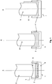
- the method of manufacturing a closed-ended pressure vessel as shown in Fig. 1 involves the use of extrusion apparatus 1 in the backward extrusion of a metallic billet 2.
- the billet of metallic material for example an aluminium alloy
- a ram 5 which is preferably cylindrical in cross-section and with substantially parallel side walls, is arranged for reciprocal movement along a common axis X of the ram 5, the die 4 and the billet 2.
- the ram 5 is inserted into the die cavity 3 so that the end face 6 of the ram 5 engages the surface of the billet 2 facing towards the opening of the die cavity 3.
- the radial separation of the side wall of the ram 5 from the cylindrical inner surface of the die 4 generally corresponds to the thickness of the cylindrical side wall of the pressure vessel.
- the internal profile of the closed end of the pressure vessel corresponds to the external profile of the ram 5.
- Formation of the closed end of the pressure vessel results in an initial generally cup-shaped extrudate with a base, parallel side walls and an open top.
- the open top of the extrudate is then squared off and heated, typically induction heated to 300-450°C, prior to the formation of a neck using conventional swaging or spinning techniques.
- the resulting hallow body is solution heat treated; quenched, generally in cold water; and finally aged.
- Conventional finishing processes such as autofrettage and shot peening, may also be performed to complete manufacture of the pressure vessel.
- the extrusion method described above differs from conventional backward extrusion of a metallic billet by virtue of the use of novel and inventive extrusion apparatus 1.
- the features of the extrusion apparatus 1 are generally conventional in design with the exception of the external surface 10 of the end face of the ram 5, which is described in greater detail below.
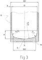
- the internal surface profile of the closed end of the pressure vessel corresponds to the profile of the external surface 10 of the ram 5 and so the external surface 10 of the ram 5 is described herein by reference to Figs. 2 to 4 which show in cross section the closed end of a pressure vessel manufactured using the die 4 and ram 5 of the extrusion apparatus 1.
- the pressure vessel has an external or outer diameter OD, which is substantially equal to the internal diameter of the cylindrical side wall of the extrusion sleeve or die 4, and an internal diameter ID which is substantially equal to the external cylindrical diameter of the external side wall of the ram 5.
- Key features of the profile of the external surface 10 of the ram 5 include a central point 12 where the end of the ram 5 intersects its longitudinal axis of symmetry X, a central section 13 and at least two rings 14, 15 which connect the central point 12 to the substantially cylindrical side wall 11 of the ram 5.
- the central section 13 and the two rings 14 and 15 are all rotationally symmetric with respect to the axis X and concentric with respect to each other.
- the surface profiles of the central section 13 and the two rings 14 and 15 in the vertical cross-section of Figs. 3 and 4 can be clearly seen to have differing but intersecting surface curvatures.
- the surface curvature of the central section 13, the intermediate ring 14 and the outermost ring 15 extends between their boundaries and has a radius of R, r, and Rc respectively.
- the central point 12 lies at the centre of the central section 13.
- the surface profile of the central section 13 has a curvature of radius R between 0.5ID and 1.2ID, more preferably between 0.8ID and 1.2ID, and more preferably still 1ID ⁇ R ⁇ 1.2ID.
- the outer edge of the central section 13 joins or intersects the inner edge of the first knuckle section, referred to herein as an intermediate ring 14, which has a curvature of radius r between 0.1ID and 0.5ID, more preferably between 0.1ID and 0.25ID, and more preferably still 0.1ID ⁇ r ⁇ 0.15ID.
- Rc ID/(3 ⁇ 2)
- Rc ID/(3 ⁇ 1)
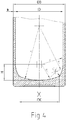
- the radius R of the central section's surface curvature is measured from a point (origin) a distance R along the axis X. Furthermore the intersection of the central section 13 with the intermediate ring 14, the intersection of the intermediate ring 14 with the outermost ring 15, and the intersection of the outermost ring 15 with the cylindrical side wall 11 are each blended to ensure no discontinuities in the surface profile of the end of the ram 5 that might be detrimental to the strength of the cylinder. This requires that at each intersection tangents to the curvatures of the surfaces either side of the junction (the tangents being orthogonal to the line of the junction) are substantially aligned and preferably common. In the case of the intersection of the outermost ring 15 with the cylindrical side wall 11, the tangent to the surface curvature of the outermost ring 15 (orthogonal to the line if the intersection) is substantially aligned with the surface of the cylindrical side wall 11.
- the radius Rc of the outermost ring's surface curvature is measured from a point (origin) that lies in a cross-sectional plane through the ram 5 at height H above the central point 12.
- the radius r of the intermediate ring 14 is measured from a point (origin) corresponding to the intersection of Rc-r and R-r.
- the cross sectional diameter IDC of the center of the intermediate ring 14 is less than or equal to OD-(3x a ), where OD is the external cylindrical diameter of the pressure vessel (equal to the internal cylindrical diameter of the die 4) and a is the thickness of the pressure vessel wall (equal to the separation of the cylindrical side walls of the die 4 and the ram 5).
- the internal surface profile of the pressure cylinder may comprise more than one intermediate ring with each intermediate ring having its own radius of surface curvature and with each of the intermediate rings blending at its edges with the edges of adjacent rings i.e. the tangents to the surface curvature of each intermediate ring at the edges of the intermediate ring being substantially aligned with the tangents to the surface curvatures of adjacent rings.
- the central 13 may consist of an inner central section which is substantially flat and an outer central section, concentric to the inner central section, which has a surface curvature of radius R.
- a first set of exemplary dimensions for a die 4 and ram 5 of extrusion apparatus according to the present invention and the corresponding dimensions of the 5 litre AA7060 cylinder liner produced using the die and ram are set out below.
- a second set of exemplary dimensions for a conventional 2 litre carbon fibre hoop wrap AA7060 alloy liner (and the corresponding dimensions of the die 4 and ram 5 of conventional extrusion apparatus) ( Shape A ) and similarly for a 2 litre carbon fibre hoop wrap AA7060 alloy liner (and its corresponding die and ram) ( Shape B ) in accordance with the present invention are set out bellow: Shape A (mm) Shape B (mm) OD 96.7 96.7 ID 88.5 88.5 a 4.1 4.1 H 22 29.5 R 105 101 r 11 11 Rc 44.4 44.4 a' (at H) 4.08 4.13
- test pressure vessels having the dimensions set out in Example 1 were tested to failure.
- Five groups each of five pressure vessels were subjected to a pressure cycling test with each group of pressure vessels having had a different amount of autofrettage.
- the remaining two pressure vessels (having had no autofrettage) were subjected to a burst test.
- Each of the test pressure vessels was a 5 litre carbon fibre hoop wrap 7060 aluminium alloy pressure vessel manufactured in a cold backward extrusion process using a die 4 and ram 5 having the dimensions set out in Example 1. Details of the amount of autofrettage for each group of pressure vessels and the results of the tests are set out below in Table 3.
- autofrettage offers improved failure performance for pressure vessels having a closed end joined to a cylindrical side wall by a knuckle region.
- the autofrettage pressure is generally between 75% and 95% of the minimum burst pressure according to the relevant standard.
- Aluminium high pressure gas cylinders are usually designed so that the stress in the cylindrical side wall at service pressure does not exceed half the alloy yield stress, and that the cylinder burst pressure is at least 2.5 times the operating pressure.
- the design should be such that wall stresses do not exceed 225 MPa.
- Finite element analysis (FEA) of a hoop wrap pressure vessel manufactured using the method and apparatus described above has revealed that the internal profile of the closed end of pressure vessels according to the present invention results in noticeably lower maximum stresses in comparison to pressure vessels with a conventional internal profile at the closed end.
- the structure in this case the closed end of the pressure vessel
- the elements are assumed to have a simplified pattern of deformation (linear or quadratic etc.) and are connected at 'nodes' normally located at corners or edges of the elements.
- the elements are then assembled mathematically using basic rules of structural mechanics i.e. equilibrium of forces and continuity of displacements, resulting in a large system of simultaneous equations.
- the deformed shape of the structure under load may be obtained and internal stresses and strains may be calculated from the deformed shape.
- Analysis 1 corresponds to a conventional pressure vessel adjusted to incorporate three concentric intersecting radii, whereas Analysis 4 corresponds to a pressure vessel manufactured using the method and apparatus described above, Analysis 4 being a particularly preferred embodiment.
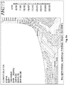
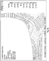
- Figs. 5a and 5b show the principal stresses and the Von Mises stresses for Analysis 1 and Figs. 6a and 6b show the principal stresses and the Von Mises stresses for Analysis 4.
- Figs. 5 and 6 show that the location of maximum stress in the knuckle region remains substantially the same for Analysis 1 and Analysis 4 (the same is also true for Analysis 2 and Analysis 3, not shown).
- Figs. 5 and 6 also show that for Type II pressure vessels manufactured using the method and apparatus described above, the maximum Von Mises stress remains at the inner surface of the pressure vessel even after autofrettage.
- Table 4 clearly show that the absolute value of the first principal stress and the Von Mises stress are significantly lower for Analysis 4 than for any of the other Analyses.
- the FEA shows that the main factors contributing to the lowering of the maximum stress are the value of H and Rc.
- the above method and apparatus are particularly suited, but not limited, to the cold extrusion manufacture of pressure vessels for AA6XXX and AA7XXX series of aluminium alloys (according to the Aluminum Association Inc. Register 2009) and to both Type I cylinders and Type II cylinder liners respectively which meet the fatigue requirements of hoop wrapped pressure vessel standards, for example, EN12257 and ISO11119-1 and corresponding standards in other regions of the world.
- Type II cylinders which at least match and often exceed the failure performance of equivalent conventional cylinders may be manufactured using autofrettage at lower pressures.
Landscapes
- Engineering & Computer Science (AREA)
- Mechanical Engineering (AREA)
- General Engineering & Computer Science (AREA)
- Filling Or Discharging Of Gas Storage Vessels (AREA)
- Pressure Vessels And Lids Thereof (AREA)
- Shaping Metal By Deep-Drawing, Or The Like (AREA)
- Extrusion Of Metal (AREA)
Description
- The present invention relates to a method of manufacture of vessels adapted to contain pressurised fluids, the manufacturing apparatus thereof and pressure vessels manufactured using this method. More particularly, the present invention concerns a backward extrusion method for the manufacture of metallic vessels capable of containing fluids under pressure, the extrusion apparatus thereof and pressure vessels manufactured according to that method. In particular, but not exclusively, the present invention relates to apparatus and a manufacturing method for closed-ended hoop wrap gas cylinders adapted to contain gases at pressures above atmospheric pressure and to the closed-ended hoop wrap gas cylinders produced by the method.
- Currently pressure vessels are manufactured in aluminium, steel and composite materials. Type I pressure vessels are formed solely of metallic material such as steel or aluminium alloys. In contrast Type II pressure vessels comprise a metallic vessel (usually made of aluminium) which has a filamentous composite sleeve, formed for example of an epoxy resin, aramid and/or carbon fiber, surrounding the cylindrical side wall only of the vessel (referred to herein as hoop wrap). Type II pressure vessels are generally lighter in weight than Type I pressure vessels because the metallic vessel wall of a Type II pressure vessel can be thinner than a Type I pressure vessel without loss of performance. For both Type I and Type II pressure vessels, repeated dispensing and vessel re-filling of gas under pressure causes the vessel to flex and such flexing can encourage the propagation of cracks in the vessel wall.
- For metallic and composite pressure vessels conventional manufacturing methods include hot and cold extrusion of a billet comprising a metallic material, usually an aluminium alloy for high pressure vessels.
US3648351 provides an early example of backward extrusion of a closed-end hallow metallic vessel in which a slug or billet of a metallic material is forced to extrude up the sides of a ram the end of which bears down on the slug within a die cavity.WO96/11757 - In addition, autofrettage has been used to improve pressure vessel fatigue resistance. Autofrettage involves applying a pressure within the bore of the vessel sufficient to plastically deform the metal at the inner surface. The technique produces compressive residual stresses at or near the internal surface, and this enhances the fatigue resistance of the vessel subjected to cyclic internal pressure loading.
WO96/11759 independent claims 1, 7 and 9 is based, describes the use of autofrettage in the manufacture of pressure vessels to cause regions of peak stress in the pressure vessel wall to move away from an internal or external wall surface. - The present invention seeks to provide a pressure vessel manufacturing method, manufacturing apparatus and pressure vessels manufactured using the method which improves the pressure vessel's resistance to fatigue.
- The present invention also seeks to provide a pressure vessel manufacturing method, manufacturing apparatus and pressure vessels manufactured using the method which reduces the likelihood of premature failure.
- The present invention further seeks to provide a cold extrusion manufacturing method and manufacturing apparatus particularly suited to manufacturing AA6XXX and AA7XXX series aluminium high pressure cylinders and cylinder liners.
- Still further, the present invention seeks to provide closed-ended hoop wrap pressure vessels with improved performance in comparison to conventional closed-ended hoop wrap pressure vessels.
- The present invention separately seeks to provide pressure vessels which meet the regulatory requirements of pressure vessel standards such as: EN12257 and/or IS011119-1 and which have a compound curve internal surface.
- The present invention therefore provides a method of forming a closed-ended pressure vessel, the method comprising: positioning a billet of an extrudable metal into a die, said billet having an axis and a forward surface; using a ram with a longitudinal axis of symmetry, an end face region and a substantially cylindrical side wall to cause the metal to extrude by driving the end face region of the ram into the forward surface of the billet along the axis of the billet so as to cause the metal to extrude into the space between the ram and the die and along the cylindrical side wall of the ram to form an extrudate; and removing the extrudate from the die and shaping the open end of the extrudate to form a shoulder and a neck, whereby the end face region of the ram has a surface profile comprising a central section, at least one intermediate ring and an outermost ring with intersecting but differing curvatures of radii: R, r, and Rc respectively, the central section, the at least one intermediate ring and the outermost ring connecting a central point where the end face intersects the longitudinal axis of the ram with the cylindrical side wall of the ram at an axial distance H from the central point, the axial distance H having a range 0.28ID to 0.5ID, where ID is the cross-sectional diameter of the cylindrical side wall of the ram.
- Preferably the axial distance H is in the range 0.3ID and 0.4ID.
- In a particularly preferred embodiment the axial distance H is substantially equal to ID/3.
- The central section preferably has a radius of curvature R in the range 0.5ID and 1.2ID.
- More preferably the central section has a radius of curvature R substantially equal to 1.1ID.
- More preferably still the intermediate ring has a radius of curvature r in the range between 0.1ID and 0.5ID.
- The intermediate ring preferably has a radius of curvature r in the range 0.12ID and 0.13ID.
- In a further preferred embodiment the end face region of the ram may have a surface profile including at least two intermediate rings each with a different radius of surface curvature.
- Preferably the outermost ring has a radius of curvature Rc in the range ID/(3±2).
- More preferably still the outermost ring has a radius of curvature Rc in the range ID/(3±1).
- The outermost ring preferably has a radius of curvature Rc substantially equal to ID/2.
- The method may further comprise the step of subjecting the pressure vessel to autofrettage.
- The billet may comprise a AA6XXX series aluminium alloy.
- In a particularly preferred embodiment the billet comprises a AA7XXX series aluminium alloy.
- In a second aspect the present invention provides extruding apparatus for use in the manufacture of a closed-ended pressure vessel, the extruding apparatus comprising a die for receiving a billet of an extrudable metal and a ram having a longitudinal axis of symmetry, an end face region and a substantially cylindrical side wall, the end face region of the ram having a surface profile comprising a central section, at least one intermediate ring and an outermost ring with intersecting but differing curvatures of radii: R, r, and Rc respectively, the central section, the at least one intermediate ring and the outermost ring connecting a central point where the end face intersects the longitudinal axis of the ram with the cylindrical side wall of the ram at an axial distance H from the central point, the axial distance H having a range 0.28ID to 0.5ID, where ID is the cross-sectional diameter of the cylindrical side wall of the ram.
- Preferably the axial distance H is in the range 0.3ID and 0.4ID.
- In a particularly preferred embodiment the axial distance H is substantially equal to ID/3.
- The central section preferably has a radius of curvature R in the range 0.5ID and 1.2ID.
- More preferably the central section has a radius of curvature R substantially equal to 1.1ID.
- The intermediate ring preferably has a radius of curvature r in the range between 0.1ID and 0.5ID.
- More preferably the intermediate ring has a radius of curvature r in the range between 0.12ID and 0.13ID.
- In a further preferred embodiment the end face region of the ram may have a surface profile including at least two intermediate rings each with a different radius of surface curvature.
- The outermost ring preferably has a radius of curvature Rc in the range ID/(3±2).
- More preferably the outermost ring has a radius of curvature Rc in the range ID/(3±1).
- More preferably still the outermost ring has a radius of curvature Rc substantially equal to ID/2.
- In a third aspect the present invention provides a closed-ended pressure vessel formed of an extrudable metal, the pressure vessel comprising a closed-end section, a substantially cylindrical side wall with a cross sectional internal diameter ID, a shoulder and a neck and having a longitudinal axis of symmetry, the internal surface profile of the closed-end section comprising a central section, at least one intermediate ring and an outermost ring with intersecting but differing curvatures of radii: R, r, and Rc respectively, the central section, the at least intermediate ring and the outermost ring connecting a central point where
the closed-end section intersects the longitudinal axis with the cylindrical side wall at an axial distance H from the central point, the axial distance H having a range 0.28ID to 0.5ID. - Preferably the axial distance H is in the range 0.3ID and 0.4ID.
- In a particularly preferred embodiment the axial distance H is substantially equal to ID/3.
- The central section preferably has a radius of curvature R in the range 0.5ID and 1.2ID.
- More preferably the central section has a radius of curvature R substantially equal to 1.1ID.
- The intermediate ring preferably has a radius of curvature r in the range between 0.1ID and 0.5ID.
- More preferably the intermediate ring has a radius of curvature r in the range between 0.12ID and 0.13ID.
- In a further preferred embodiment, the internal surface profile of the closed-ended section may include at least two intermediate rings each with a different radius of surface curvature.
- The outermost ring preferably has a radius of curvature Rc in the range ID/(3±2).
- More preferably the outermost ring has a radius of curvature Rc in the range ID/(3±1).
- In a particularly preferred embodiment the outermost ring has a radius of curvature Rc substantially equal to ID/2.
- The closed-ended pressure vessel may comprise a AA6XXX series aluminium alloy.
- In a particularly preferred embodiment the closed-ended pressure vessel comprising a AA7XXX series aluminium alloy.
- In a further aspect the present invention provides a composite pressure vessel comprises a closed-ended pressure vessel as described above and a sleeve of a composite material.
- The composite material may be selected from a carbon fibre composite, basalt fibre, aramid and/or fibre glass fibre.
- The manufacturing method and manufacturing apparatus of the present invention enables closed-ended high pressure vessels to be manufactured using cold or warm extrusion which have an equivalent or improved lifetime in contrast to equivalent high pressure vessels manufactured using hot extrusion and which achieve equivalent performance even with lower pressure autofrettage.
- An embodiment of the present invention will now be described by way of example only with reference to the accompanying drawings, in which:
-
Fig. 1 illustrates schematically a series of stages in backward extrusion of a metallic billet to form a closed-ended pressure vessel; -
Fig. 2 is perspective view through a cross section of the closed end of a pressure vessel according to the present invention; -
Fig. 3 is a detailed cross-section of the closed end of the pressure vessel ofFig. 2 ; -
Fig. 4 illustrates the relationship of the surface curvature radii of the closed end of the pressure vessel ofFig. 2 ; -
Figs. 5a and5b illustrate the first principal stresses and the Von Mises stresses using finite element analysis of the base of a conventional hoop wrap pressure vessel liner; and -
Figs. 6a and6b illustrate the first principal stresses and the Von Mises stresses using finite element analysis of the base of a hoop wrap pressure vessel liner in accordance with the present invention. - Although hot extrusion (in which the extrusion is typically performed above the recrystallization temperature) according to the present invention is possible, cold and/or warm extrusion (in which the extrusion is performed below the recrystallization temperature) is preferred being a lower cost procedure. Warm extrusion is typically performed with a starting billet temperature at 100-250°C whereas cold extrusion is typically performed with a starting billet temperature at below 100°C, preferably ambient temperature. However, the precise extrusion conditions are not material to this invention and conventional conditions for extrusion may be employed.
- The method of manufacturing a closed-ended pressure vessel as shown in
Fig. 1 involves the use ofextrusion apparatus 1 in the backward extrusion of ametallic billet 2. In overview, the billet ofmetallic material 2, for example an aluminium alloy, is positioned at the bottom of acavity 3 in a die 4 (also referred to as an extrusion sleeve). Aram 5, which is preferably cylindrical in cross-section and with substantially parallel side walls, is arranged for reciprocal movement along a common axis X of theram 5, thedie 4 and thebillet 2. Theram 5 is inserted into thedie cavity 3 so that theend face 6 of theram 5 engages the surface of thebillet 2 facing towards the opening of thedie cavity 3. Continued reciprocal movement of theram 5 towards the closed end of thedie cavity 3 forces theend face region 6 of the ram into themetallic billet 2. This causes the metallic material of thebillet 2 to extrude along the side walls surface of theram 5. The speed with which the extrudate exits from thedie cavity 3 is typically in the range 50-500 cm/min and lubrication (not shown) may also be provided at least where theend face 6 of theram 5 contacts thebillet 2 to reduce the extrusion pressure required. Reciprocal movement of theram 5 is continued until theend face 6 of the ram reaches a predetermined distance away from the interior floor of thedie cavity 3 generally corresponding to the desired thickness of the closed end of the resulting pressure vessel. Similarly, the radial separation of the side wall of theram 5 from the cylindrical inner surface of thedie 4 generally corresponds to the thickness of the cylindrical side wall of the pressure vessel. Thus, the internal profile of the closed end of the pressure vessel corresponds to the external profile of theram 5. - Formation of the closed end of the pressure vessel results in an initial generally cup-shaped extrudate with a base, parallel side walls and an open top. The open top of the extrudate is then squared off and heated, typically induction heated to 300-450°C, prior to the formation of a neck using conventional swaging or spinning techniques. The resulting hallow body is solution heat treated; quenched, generally in cold water; and finally aged. Conventional finishing processes, such as autofrettage and shot peening, may also be performed to complete manufacture of the pressure vessel.
- The extrusion method described above differs from conventional backward extrusion of a metallic billet by virtue of the use of novel and
inventive extrusion apparatus 1. The features of theextrusion apparatus 1 are generally conventional in design with the exception of theexternal surface 10 of the end face of theram 5, which is described in greater detail below. As mentioned earlier, the internal surface profile of the closed end of the pressure vessel corresponds to the profile of theexternal surface 10 of theram 5 and so theexternal surface 10 of theram 5 is described herein by reference toFigs. 2 to 4 which show in cross section the closed end of a pressure vessel manufactured using thedie 4 andram 5 of theextrusion apparatus 1. - In overview and with reference to
Figs. 2 and3 the pressure vessel has an external or outer diameter OD, which is substantially equal to the internal diameter of the cylindrical side wall of the extrusion sleeve or die 4, and an internal diameter ID which is substantially equal to the external cylindrical diameter of the external side wall of theram 5. The difference a between the internal and external diameters corresponds to the thickness of the substantiallycylindrical side wall 11 of the pressure vessel, i.e. a = (OD-ID)/2 which also substantially corresponds to the clearance or radial difference of the side walls of theram 5 and thedie 4. - Key features of the profile of the
external surface 10 of theram 5 include acentral point 12 where the end of theram 5 intersects its longitudinal axis of symmetry X, acentral section 13 and at least tworings central point 12 to the substantiallycylindrical side wall 11 of theram 5. When viewed along the axis X, thecentral section 13 and the tworings central section 13 and the tworings Figs. 3 and4 can be clearly seen to have differing but intersecting surface curvatures. In each case, the surface curvature of thecentral section 13, theintermediate ring 14 and theoutermost ring 15 extends between their boundaries and has a radius of R, r, and Rc respectively. - The
central point 12 lies at the centre of thecentral section 13. The surface profile of thecentral section 13 has a curvature of radius R between 0.5ID and 1.2ID, more preferably between 0.8ID and 1.2ID, and more preferably still 1ID<R<1.2ID. The outer edge of thecentral section 13 joins or intersects the inner edge of the first knuckle section, referred to herein as anintermediate ring 14, which has a curvature of radius r between 0.1ID and 0.5ID, more preferably between 0.1ID and 0.25ID, and more preferably still 0.1ID<r<0.15ID. In turn, the outer edge of theintermediate ring 14 joins or intersects the inner edge of the second knuckle section referred to herein as the second oroutermost ring 15 which has a curvature of radius Rc = ID/(3±2), more preferably Rc = ID/(3±1), more preferably still 0.4ID< Rc <0.6ID. Although the range of potential curvatures for thecentral section 13 and the tworings particular ram 5, the central section and the two rings defining theexternal surface 10 will each have a surface curvature that differs from the surface curvatures of the others and with the radius of the surface curvature of theintermediate ring 14 always smaller than the curvature of thecentral section 13 and theoutermost ring 15. - With reference to
Fig. 4 , as thecentral section 13 is rotationally symmetric with respect to the axis X, the radius R of the central section's surface curvature is measured from a point (origin) a distance R along the axis X. Furthermore the intersection of thecentral section 13 with theintermediate ring 14, the intersection of theintermediate ring 14 with theoutermost ring 15, and the intersection of theoutermost ring 15 with thecylindrical side wall 11 are each blended to ensure no discontinuities in the surface profile of the end of theram 5 that might be detrimental to the strength of the cylinder. This requires that at each intersection tangents to the curvatures of the surfaces either side of the junction (the tangents being orthogonal to the line of the junction) are substantially aligned and preferably common. In the case of the intersection of theoutermost ring 15 with thecylindrical side wall 11, the tangent to the surface curvature of the outermost ring 15 (orthogonal to the line if the intersection) is substantially aligned with the surface of thecylindrical side wall 11. - A cross section taken through the
ram 5 at the junction of theoutermost ring 15 with thecylindrical side wall 11 intersects the axis X a distance H above thecentral point 12. The distance H is between 0.28ID and 0.5ID, more preferably 0.3ID and 0.4ID, more preferably still H = ID/3. As the tangent to the surface curvature of theoutermost ring 15 is substantially aligned with thecylindrical wall 11 at the junction of theoutermost ring 15 with theside wall 11, the radius Rc of the outermost ring's surface curvature is measured from a point (origin) that lies in a cross-sectional plane through theram 5 at height H above thecentral point 12. - Thus to ensure that the curvature of the
intermediate ring 14 is blended with both thecentral section 13 and theoutermost ring 15, the radius r of theintermediate ring 14 is measured from a point (origin) corresponding to the intersection of Rc-r and R-r. Furthermore, the cross sectional diameter IDC of the center of theintermediate ring 14 is less than or equal to OD-(3xa), where OD is the external cylindrical diameter of the pressure vessel (equal to the internal cylindrical diameter of the die 4) and a is the thickness of the pressure vessel wall (equal to the separation of the cylindrical side walls of thedie 4 and the ram 5). - Although the figures illustrate a single
intermediate ring 14, the internal surface profile of the pressure cylinder (and so also the external surface profile of the ram 5) may comprise more than one intermediate ring with each intermediate ring having its own radius of surface curvature and with each of the intermediate rings blending at its edges with the edges of adjacent rings i.e. the tangents to the surface curvature of each intermediate ring at the edges of the intermediate ring being substantially aligned with the tangents to the surface curvatures of adjacent rings. Furthermore, although the figures illustrate the surface curvature of thecentral section 13 to be defined by a single radius it is also envisaged that the central 13 may consist of an inner central section which is substantially flat and an outer central section, concentric to the inner central section, which has a surface curvature of radius R. - A first set of exemplary dimensions for a
die 4 andram 5 of extrusion apparatus according to the present invention and the corresponding dimensions of the 5 litre AA7060 cylinder liner produced using the die and ram are set out below. - total height of cylinder = 465 mm
- total weight of cylinder = 4.8 Kg
- A second set of exemplary dimensions for a conventional 2 litre carbon fibre hoop wrap AA7060 alloy liner (and the corresponding dimensions of the
die 4 andram 5 of conventional extrusion apparatus) (Shape A) and similarly for a 2 litre carbon fibre hoop wrap AA7060 alloy liner (and its corresponding die and ram) (Shape B) in accordance with the present invention are set out bellow:Shape A (mm) Shape B (mm) OD 96.7 96.7 ID 88.5 88.5 a 4.1 4.1 H 22 29.5 R 105 101 r 11 11 Rc 44.4 44.4 a' (at H) 4.08 4.13 - Comparative failure performance test results for pressure vessels manufactured under cold extrusion using the extrusion apparatus described in Example 2 and of 2 litre hoop wrap 7060 aluminium alloy liners (Shape A) manufactured using cold extrusion and a conventional backward extrusion die are set out below in Table 1.
Table 1 Shape A Shape B Number of refill cycles to failure Failure Site Number of refill cycles to failure Failure Site 11749 0 Sample 120226 2 10954 1 Sample 216255 2 12076 1 Sample 317918 2 9614 0 Sample 415190 3 9820 1 Sample 518680 2 Sample 615681 2 Failure site 0 = leak, position unknown;
Failure site 1 = rupture at cylinder bottom;
Failure site 2 = leak in the cylinder body; and
Failure site 3 = leak in the shoulder. - The lifetime and failure characteristics of 5 litre hoop wrap 7060 aluminium alloy liners (Shape B) manufactured under cold extrusion using the apparatus described in Example 1 above were compared with the performance of 5 litre hoop wrap 7060 aluminium alloy liners (Shape A) also manufactured using cold extrusion but with a conventional backward extrusion die. The results in terms of lifetime (number of refill cycles to failure) and failure sites are set out below in Table 2.
Table 2 Shape A Shape B No. of test cylinders 5 11 Minimum number of refill cycles to failure 10736 15343 Maximum number of cycles to failure 16513 20000 Average number of cycles to failure 14067 17754 Failure sites 1 x leak in cylinder body 10 x leak in the cylinder body 2 x leak in lower part of cylinder body 1 x test stopped with no leak 1 x rupture in the cylinder bottom - The results of Tables 1 and 2 clearly show a significant improvement in failure performance in comparison to equivalent conventional pressure vessels.
- Twenty seven test pressure vessels having the dimensions set out in Example 1 were tested to failure. Five groups each of five pressure vessels were subjected to a pressure cycling test with each group of pressure vessels having had a different amount of autofrettage. The remaining two pressure vessels (having had no autofrettage) were subjected to a burst test. Each of the test pressure vessels was a 5 litre carbon fibre hoop wrap 7060 aluminium alloy pressure vessel manufactured in a cold backward extrusion process using a
die 4 andram 5 having the dimensions set out in Example 1. Details of the amount of autofrettage for each group of pressure vessels and the results of the tests are set out below in Table 3.Table 3 Number of test samples Autofrettage pressure Value (BAR) Internal shot peening Results: average number of refill cycles to Failure 5 Without 0 YES 14084 (a) 5 Approved value 640 YES 18470 (a) 5 Approved value+10% 704 YES 24517 (a) 5 Approved value+20% 768 YES 26116 (b) 5 Approved value 640 NO 15856 (a) 2 Without 0 NO Burst pressure=832 BAR Expansion volume=512cm3 (a) represents failure in the cylinder body wall
(b) represents failures at different parts of the cylinder. - As discussed in
WO96/11759 - The information in Tables 1 to 3 clearly show that hoop wrap pressure vessels manufactured according to the method and apparatus of the present invention also benefit from autofrettage and shot peening, offering a surprising improvement in failure performance in comparison to equivalent conventional pressure vessels. This enables pressure vessels according to the method and apparatus of the present invention to deliver at least equivalent and potentially improved failure performance at lower autofrettage pressures.
- Finite element analysis (FEA) of a hoop wrap pressure vessel manufactured using the method and apparatus described above has revealed that the internal profile of the closed end of pressure vessels according to the present invention results in noticeably lower maximum stresses in comparison to pressure vessels with a conventional internal profile at the closed end.
- With FEA the structure (in this case the closed end of the pressure vessel) is broken down into many small pieces (finite number of elements) of various types, sizes and shapes. The elements are assumed to have a simplified pattern of deformation (linear or quadratic etc.) and are connected at 'nodes' normally located at corners or edges of the elements. The elements are then assembled mathematically using basic rules of structural mechanics i.e. equilibrium of forces and continuity of displacements, resulting in a large system of simultaneous equations. By solving the system of simultaneous equations the deformed shape of the structure under load may be obtained and internal stresses and strains may be calculated from the deformed shape.
- The finite element model (FEM) was based on a 7060 aluminium alloy liner and a carbon composite sleeve with ID=88.5 combined with 4 different sets of dimensions for the internal surface profile of the pressure vessel:
Analysis 1,Analysis 2,Analysis 3 andAnalysis 4. The FEA subjected each Analysis to the following loading steps: autofrettage pressure = 600 BAR; service pressure = 300 BAR; test pressure = 450 BAR and minimum design burst = 752 BAR to identify the first principal stress and the Von Mises stress at the test pressure of 450 BAR after autofrettage the results of which are set out in Table 4 below;Analysis 1 corresponds to a conventional pressure vessel adjusted to incorporate three concentric intersecting radii, whereasAnalysis 4 corresponds to a pressure vessel manufactured using the method and apparatus described above,Analysis 4 being a particularly preferred embodiment.Analyses Table 4 First Principal Stress (Mpa) Von Mises Stress (Mpa) H (mm) R (mm) r (mm) Rc (mm) Analysis 1318 306 22 105 11 44.2 Analysis 2323 308 22.125 77.36 8.85 88.5 Analysis 3285 278 22.125 111.2 14.5 29.5 Analysis 4241 235 29.5 100.5 11 44.25 -
Figs. 5a and5b show the principal stresses and the Von Mises stresses forAnalysis 1 andFigs. 6a and6b show the principal stresses and the Von Mises stresses forAnalysis 4.Figs. 5 and6 show that the location of maximum stress in the knuckle region remains substantially the same forAnalysis 1 and Analysis 4 (the same is also true forAnalysis 2 andAnalysis 3, not shown).Figs. 5 and6 also show that for Type II pressure vessels manufactured using the method and apparatus described above, the maximum Von Mises stress remains at the inner surface of the pressure vessel even after autofrettage. However, the results in Table 4 clearly show that the absolute value of the first principal stress and the Von Mises stress are significantly lower forAnalysis 4 than for any of the other Analyses. Also the FEA shows that the main factors contributing to the lowering of the maximum stress are the value of H and Rc. - The above method and apparatus are particularly suited, but not limited, to the cold extrusion manufacture of pressure vessels for AA6XXX and AA7XXX series of aluminium alloys (according to the Aluminum Association Inc. Register 2009) and to both Type I cylinders and Type II cylinder liners respectively which meet the fatigue requirements of hoop wrapped pressure vessel standards, for example, EN12257 and ISO11119-1 and corresponding standards in other regions of the world. Moreover, with the above method and apparatus Type II cylinders which at least match and often exceed the failure performance of equivalent conventional cylinders may be manufactured using autofrettage at lower pressures.
- It is to be understood that the embodiments described above are only selected preferred exemplary embodiments. Changes may be made to the manufacturing method, manufacturing apparatus and to the pressure vessels produced by the method and apparatus described above without departing from the scope of the invention as claimed in the accompanying claims.
| Ram and | 5 litre AA7060 cylinder liner | (mm) |
| Internal diameter of die | OD | 140 |
| External diameter of ram | ID | 129 |
| Radial separation of die from cylindrical surface of ram | a | 5.5 |
| Axial height of contoured end of ram to cylindrical side wall | H | 43 |
| Innermost ring radius of contoured ram surface | R | 146 |
| Second ring radius of contoured ram surface | r | 16 |
| Outermost ring radius of contoured ram surface | Rc | 64 |
Claims (18)
- A method of forming a closed-ended pressure vessel, the method comprising:positioning a billet (2) of an extrudable metal into a die (4), said billet (2) having an axis and a forward surface;using a ram (5) with a longitudinal axis of symmetry (x), an end face region (6) and a substantially cylindrical side wall (11) to cause the metal to extrude by driving the end face region (6) of the ram (5) into the forward surface of the billet along the axis of the billet so as to cause the metal to extrude into the space between the ram (5) and the die (4) and along the cylindrical side wall (11) of the ram to form an extrudate; andremoving the extrudate from the die (4) and shaping the open end of the extrudate to form a shoulder and a neck,characterised in that the end face region (6) of the ram (5) has a surface profile (10) comprising a central section (13), at least one intermediate ring (14) and an outermost ring (15) with intersecting but differing surface curvatures of radii: R, r, and Rc respectively, the central section (13), the at least one intermediate ring (14) and the outermost ring (15) connecting a central point (12) where the end face region (6) intersects the longitudinal axis of the ram (5) with the cylindrical side wall (11) of the ram at an axial distance H from the central point (12), the axial distance H having a range 0.28ID to 0.5ID, where ID is the cross-sectional diameter of the cylindrical side wall (11) of the ram.
- The method as claimed in claim 1, wherein the axial distance H is in the range 0.3ID and 0.4ID.
- The method as claimed in any of the preceding claims, wherein the central section (13) has a radius of curvature R in the range 0.5ID and 1.2ID.
- The method as claimed in any of the preceding claims, wherein the at least one intermediate ring (14) has a radius of curvature r in the range between 0.1ID and 0.5ID.
- The method as claimed in any one of claims 1 to 4, wherein the end face region (6) of the ram (5) has a surface profile including at least two intermediate rings (14) each with a different radius of surface curvature.
- The method as claimed in any one of claims 1 to 5, wherein the outermost ring (15) has a radius of curvature Rc substantially equal to ID/2.
- Extruding apparatus (1) for use in the manufacture of a closed-ended pressure vessel, the extruding apparatus (1) comprising a die (4) for receiving a billet (2) of an extrudable metal and a ram (5) having a longitudinal axis of symmetry (x), an end face region (6) and a substantially cylindrical side wall (11), characterized in that the end face region (6) of the ram (5) has a surface profile (10) comprising a central section (13), at least one intermediate ring (14) and an outermost ring (15) with intersecting but differing surface curvatures of radii: R, r, and Rc respectively, the central section (13), the at least one intermediate ring (14) and the outermost ring (15) connecting a central point (12) where the end face intersects the longitudinal axis of the ram (5) with the cylindrical side wall (11) of the ram (5) at an axial distance H from the central point (12), the axial distance H having a range 0.28ID to 0.5ID, where ID is the cross-sectional diameter of the cylindrical side wall (11) of the ram.
- The extruding apparatus as claimed in claim 7, wherein the end face region (6) of the ram (5) has a surface profile (10) including at least two intermediate rings (14)each with a different radius of surface curvature.
- A closed-ended pressure vessel formed of an extrudable metal, the pressure vessel comprising a closed-end section, a cylindrical side wall (11) with a cross sectional internal diameter ID, a shoulder and a neck and having a longitudinal axis of symmetry (x), characterized in that the internal surface profile of the closed-end section comprises a central section (13), at least one intermediate ring (14) and an outermost ring (15) with intersecting but differing curvatures of radii: R, r, and Rc respectively, the central section (13), the at least one intermediate ring (14) and the outermost ring (15) connecting a central point (12) where the closed-end section intersects the longitudinal axis (x) with the cylindrical side wall (11) at an axial distance H from the central point (12), the axial distance H having a range 0.28ID to 0.5ID.
- The closed-ended pressure vessel as claimed in claim 9, wherein the axial distance H is in the range 0.3ID and 0.4ID.
- The closed-ended pressure vessel as claimed in any one of claims 9 or 10, wherein the central section (13) has a radius of curvature R in the range 0.5ID and 1.2ID.
- The closed-ended pressure vessel as claimed in any one of claims 9 to 11, wherein the intermediate ring (14) has a radius of curvature r in the range between 0.1ID and 0.5ID.
- The closed-ended pressure vessel as claimed in any one of claims 9 to 12, wherein the internal surface profile of the closed-ended section includes at least two intermediate rings (14) each with a different radius of surface curvature.
- The closed-ended pressure vessel as claimed in any one of claims 9 to 13, wherein the outermost ring (15) has a radius of curvature Rc in the range ID/(3±2).
- The closed-ended pressure vessel as claimed in any one of claims 9 to 14, comprising a AA6XXX series aluminium alloy.
- The closed-ended pressure vessel as claimed in any one of claims 9 to 14, comprising a AA7XXX series aluminium alloy.
- A composite pressure vessel comprising a closed-ended pressure vessel as claimed in any one of claims 9 to 16 and a sleeve of a composite material.
- A composite pressure vessel as claimed in claim 17, wherein the composite material includes one or more of a carbon fibre, basalt fibre, aramid fibre and glass fibre.
Priority Applications (1)
| Application Number | Priority Date | Filing Date | Title |
|---|---|---|---|
| PL15728083T PL3154719T3 (en) | 2014-06-13 | 2015-05-26 | A method of manufacture of vessels for pressurised fluids and apparatus thereof |
Applications Claiming Priority (2)
| Application Number | Priority Date | Filing Date | Title |
|---|---|---|---|
| FR1455433A FR3022164B1 (en) | 2014-06-13 | 2014-06-13 | PROCESS FOR MANUFACTURING CONTAINERS FOR PRESSURIZED FLUID AND APPARATUS FOR THE PROCESS |
| PCT/GB2015/051527 WO2015189561A1 (en) | 2014-06-13 | 2015-05-26 | A method of manufacture of vessels for pressurised fluids and apparatus thereof |
Publications (2)
| Publication Number | Publication Date |
|---|---|
| EP3154719A1 EP3154719A1 (en) | 2017-04-19 |
| EP3154719B1 true EP3154719B1 (en) | 2018-03-14 |
Family
ID=51688186
Family Applications (1)
| Application Number | Title | Priority Date | Filing Date |
|---|---|---|---|
| EP15728083.5A Active EP3154719B1 (en) | 2014-06-13 | 2015-05-26 | A method of manufacture of vessels for pressurised fluids and apparatus thereof |
Country Status (11)
| Country | Link |
|---|---|
| EP (1) | EP3154719B1 (en) |
| CN (1) | CN106457327B (en) |
| AU (1) | AU2015273346B2 (en) |
| DK (1) | DK3154719T3 (en) |
| ES (1) | ES2672802T3 (en) |
| FR (1) | FR3022164B1 (en) |
| GB (1) | GB2527203B (en) |
| PL (1) | PL3154719T3 (en) |
| RU (1) | RU2683676C2 (en) |
| TR (1) | TR201807783T4 (en) |
| WO (1) | WO2015189561A1 (en) |
Cited By (1)
| Publication number | Priority date | Publication date | Assignee | Title |
|---|---|---|---|---|
| FR3126148A1 (en) * | 2021-08-11 | 2023-02-17 | Max Sardou | LINER that is to say: internal envelope of COMPOSITE TANK for HIGH PRESSURE GAS |
Families Citing this family (5)
| Publication number | Priority date | Publication date | Assignee | Title |
|---|---|---|---|---|
| EP3192737B1 (en) * | 2016-01-14 | 2020-12-02 | Safran Landing Systems UK Limited | Shock strut |
| DE102017001384A1 (en) * | 2017-02-13 | 2018-08-16 | Neuman Aluminium Fliesspresswerk Gmbh | Process for forming a molded part and molded part |
| DE102018106546A1 (en) | 2018-03-20 | 2019-09-26 | Benteler Steel/Tube Gmbh | Pipe element for gas pressure vessel and gas pressure vessel |
| CN109530471B (en) * | 2019-01-28 | 2020-03-27 | 中北大学 | A kind of extrusion forming die for thin-walled near-alpine-shaped light alloy components |
| CN120063394B (en) * | 2025-04-28 | 2025-08-01 | 中国石油大学(华东) | Intelligent auxiliary system and method for pressure vessel inspection |
Family Cites Families (15)
| Publication number | Priority date | Publication date | Assignee | Title |
|---|---|---|---|---|
| BE525077A (en) * | 1952-12-19 | |||
| BE619063A (en) * | 1961-06-20 | |||
| DE1188391B (en) * | 1962-07-03 | 1965-03-04 | Uhde Gmbh Friedrich | Flat vaulted boiler floors with low wall thickness for cylindrical pressure vessels |
| US3648351A (en) | 1968-12-16 | 1972-03-14 | Ball Corp | Method of forming a hollow composite article by extrusion |
| NL7302527A (en) * | 1973-02-23 | 1974-08-27 | ||
| US4364161A (en) * | 1980-12-29 | 1982-12-21 | The Marison Company | Method of fabricating a high pressure tank |
| IT1161016B (en) * | 1983-02-25 | 1987-03-11 | Simmel Spa | CONVEX TYPE BOTTOM, WITH SUPPORT APPENDIX, FOR TECHNICAL GAS CYLINDER, OBTAINED BY HOT FORGING FROM A STEEL BILLET, AND EQUIPMENT FOR THE FORMATION OF SUCH BOTTOM |
| SU1796309A1 (en) * | 1989-10-23 | 1993-02-23 | Rostovskij Na Donu I Selsko | Press for reversible moulding of articles |
| CA2201312C (en) | 1994-10-13 | 2006-05-02 | Nigel John Henry Holroyd | Backward extrusion method and product |
| EP0785834B1 (en) * | 1994-10-13 | 2001-05-30 | Luxfer Group Limited | Treating pressure vessels |
| TWI289482B (en) * | 2002-02-15 | 2007-11-11 | Furukawa Sky Aluminum Corp | An impact extrusion molded article, an impact extrusion molding method, and an impact extrusion molding apparatus |
| JP2005009673A (en) * | 2003-05-22 | 2005-01-13 | Furukawa Sky Kk | Manufacturing method of pressure vessel |
| RU2352417C2 (en) * | 2006-10-17 | 2009-04-20 | ОАО "Корпорация ВСМПО-АВИСМА" | Pressing method of profiles and matrix for implementation of current method |
| DE202006019115U1 (en) * | 2006-12-19 | 2008-04-30 | Otto Fuchs Kg | pressure vessel |
| BE1019903A5 (en) * | 2011-04-08 | 2013-02-05 | Composite Tank Structures B V | VAT FROM COMPOSITE MATERIAL, METHOD FOR MANUFACTURING IT, AND END CAP FOR USE IN A VAT. |
-
2014
- 2014-06-13 FR FR1455433A patent/FR3022164B1/en active Active
-
2015
- 2015-05-26 ES ES15728083.5T patent/ES2672802T3/en active Active
- 2015-05-26 CN CN201580031312.1A patent/CN106457327B/en active Active
- 2015-05-26 DK DK15728083.5T patent/DK3154719T3/en active
- 2015-05-26 AU AU2015273346A patent/AU2015273346B2/en active Active
- 2015-05-26 PL PL15728083T patent/PL3154719T3/en unknown
- 2015-05-26 WO PCT/GB2015/051527 patent/WO2015189561A1/en not_active Ceased
- 2015-05-26 RU RU2017100331A patent/RU2683676C2/en active
- 2015-05-26 TR TR2018/07783T patent/TR201807783T4/en unknown
- 2015-05-26 EP EP15728083.5A patent/EP3154719B1/en active Active
- 2015-05-26 GB GB1508964.2A patent/GB2527203B/en active Active
Cited By (1)
| Publication number | Priority date | Publication date | Assignee | Title |
|---|---|---|---|---|
| FR3126148A1 (en) * | 2021-08-11 | 2023-02-17 | Max Sardou | LINER that is to say: internal envelope of COMPOSITE TANK for HIGH PRESSURE GAS |
Also Published As
| Publication number | Publication date |
|---|---|
| GB201508964D0 (en) | 2015-07-01 |
| ES2672802T3 (en) | 2018-06-18 |
| AU2015273346B2 (en) | 2018-12-20 |
| CN106457327A (en) | 2017-02-22 |
| RU2683676C2 (en) | 2019-04-01 |
| DK3154719T3 (en) | 2018-06-18 |
| TR201807783T4 (en) | 2018-06-21 |
| GB2527203B (en) | 2016-05-11 |
| AU2015273346A1 (en) | 2016-12-22 |
| CN106457327B (en) | 2018-10-09 |
| GB2527203A (en) | 2015-12-16 |
| EP3154719A1 (en) | 2017-04-19 |
| RU2017100331A (en) | 2018-07-10 |
| RU2017100331A3 (en) | 2018-10-29 |
| PL3154719T3 (en) | 2018-09-28 |
| FR3022164B1 (en) | 2017-01-27 |
| WO2015189561A1 (en) | 2015-12-17 |
| FR3022164A1 (en) | 2015-12-18 |
Similar Documents
| Publication | Publication Date | Title |
|---|---|---|
| AU2015273346B2 (en) | A method of manufacture of vessels for pressurised fluids and apparatus thereof | |
| US9433995B2 (en) | Method of manufacturing pressure vessel liners | |
| US11112063B2 (en) | Sensor for a high-pressure line, and method for producing same | |
| US11179763B2 (en) | Compressive forming processes for enhancing collapse resistance in metallic tubular products | |
| US6491182B1 (en) | Treating pressure vessels | |
| WO2018151630A1 (en) | Vessel made of thermally non-hardenable aluminum alloy and method for the production thereof | |
| US11807052B2 (en) | Tire tread with a band layer | |
| US9962753B2 (en) | Tool for preforming a tube for subsequent internal high pressure forming, as well as a method for producing such a tool and for producing a component by internal high pressure forming | |
| RU2461436C1 (en) | Method of producing variable cross-section thin-wall shells | |
| RU87492U1 (en) | HIGH PRESSURE CYLINDER (OPTIONS) | |
| US12358038B2 (en) | Metallic tubular products with enhanced collapse resistance | |
| US20170013863A1 (en) | Multilayer high pressure cylindrical vessel apt in particular for high pressure processing | |
| KR100468990B1 (en) | Pressure vessel and handling of pressure vessel | |
| RU2758470C2 (en) | High-pressure cylinder (variants) and method for producing same (variants) | |
| CA2203109A1 (en) | Pressure vessel made of aluminium and a method for manufacturing such vessel | |
| Danyi et al. | TUBE FORMING BY HIGH INNER PRESSURE |
Legal Events
| Date | Code | Title | Description |
|---|---|---|---|
| PUAI | Public reference made under article 153(3) epc to a published international application that has entered the european phase |
Free format text: ORIGINAL CODE: 0009012 |
|
| 17P | Request for examination filed |
Effective date: 20161202 |
|
| AK | Designated contracting states |
Kind code of ref document: A1 Designated state(s): AL AT BE BG CH CY CZ DE DK EE ES FI FR GB GR HR HU IE IS IT LI LT LU LV MC MK MT NL NO PL PT RO RS SE SI SK SM TR |
|
| AX | Request for extension of the european patent |
Extension state: BA ME |
|
| DAV | Request for validation of the european patent (deleted) | ||
| DAX | Request for extension of the european patent (deleted) | ||
| GRAP | Despatch of communication of intention to grant a patent |
Free format text: ORIGINAL CODE: EPIDOSNIGR1 |
|
| INTG | Intention to grant announced |
Effective date: 20171004 |
|
| GRAS | Grant fee paid |
Free format text: ORIGINAL CODE: EPIDOSNIGR3 |
|
| GRAA | (expected) grant |
Free format text: ORIGINAL CODE: 0009210 |
|
| AK | Designated contracting states |
Kind code of ref document: B1 Designated state(s): AL AT BE BG CH CY CZ DE DK EE ES FI FR GB GR HR HU IE IS IT LI LT LU LV MC MK MT NL NO PL PT RO RS SE SI SK SM TR |
|
| REG | Reference to a national code |
Ref country code: GB Ref legal event code: FG4D |
|
| REG | Reference to a national code |
Ref country code: CH Ref legal event code: EP Ref country code: AT Ref legal event code: REF Ref document number: 978346 Country of ref document: AT Kind code of ref document: T Effective date: 20180315 |
|
| REG | Reference to a national code |
Ref country code: IE Ref legal event code: FG4D |
|
| RAP2 | Party data changed (patent owner data changed or rights of a patent transferred) |
Owner name: LUXFER GAS CYLINDERS LIMITED |
|
| REG | Reference to a national code |
Ref country code: DE Ref legal event code: R096 Ref document number: 602015008879 Country of ref document: DE |
|
| REG | Reference to a national code |
Ref country code: FR Ref legal event code: PLFP Year of fee payment: 4 |
|
| REG | Reference to a national code |
Ref country code: ES Ref legal event code: FG2A Ref document number: 2672802 Country of ref document: ES Kind code of ref document: T3 Effective date: 20180618 Ref country code: DK Ref legal event code: T3 Effective date: 20180611 |
|
| REG | Reference to a national code |
Ref country code: NL Ref legal event code: FP |
|
| REG | Reference to a national code |
Ref country code: DE Ref legal event code: R081 Ref document number: 602015008879 Country of ref document: DE Owner name: LUXFER GAS CYLINDERS LTD., GB Free format text: FORMER OWNER: LUXFER GAS CYLINDERS LTD., SALFORD, GB |
|
| REG | Reference to a national code |
Ref country code: LT Ref legal event code: MG4D |
|
| PG25 | Lapsed in a contracting state [announced via postgrant information from national office to epo] |
Ref country code: HR Free format text: LAPSE BECAUSE OF FAILURE TO SUBMIT A TRANSLATION OF THE DESCRIPTION OR TO PAY THE FEE WITHIN THE PRESCRIBED TIME-LIMIT Effective date: 20180314 Ref country code: LT Free format text: LAPSE BECAUSE OF FAILURE TO SUBMIT A TRANSLATION OF THE DESCRIPTION OR TO PAY THE FEE WITHIN THE PRESCRIBED TIME-LIMIT Effective date: 20180314 Ref country code: FI Free format text: LAPSE BECAUSE OF FAILURE TO SUBMIT A TRANSLATION OF THE DESCRIPTION OR TO PAY THE FEE WITHIN THE PRESCRIBED TIME-LIMIT Effective date: 20180314 Ref country code: NO Free format text: LAPSE BECAUSE OF FAILURE TO SUBMIT A TRANSLATION OF THE DESCRIPTION OR TO PAY THE FEE WITHIN THE PRESCRIBED TIME-LIMIT Effective date: 20180614 Ref country code: CY Free format text: LAPSE BECAUSE OF FAILURE TO SUBMIT A TRANSLATION OF THE DESCRIPTION OR TO PAY THE FEE WITHIN THE PRESCRIBED TIME-LIMIT Effective date: 20180314 |
|
| REG | Reference to a national code |
Ref country code: AT Ref legal event code: MK05 Ref document number: 978346 Country of ref document: AT Kind code of ref document: T Effective date: 20180314 |
|
| PG25 | Lapsed in a contracting state [announced via postgrant information from national office to epo] |
Ref country code: SE Free format text: LAPSE BECAUSE OF FAILURE TO SUBMIT A TRANSLATION OF THE DESCRIPTION OR TO PAY THE FEE WITHIN THE PRESCRIBED TIME-LIMIT Effective date: 20180314 Ref country code: LV Free format text: LAPSE BECAUSE OF FAILURE TO SUBMIT A TRANSLATION OF THE DESCRIPTION OR TO PAY THE FEE WITHIN THE PRESCRIBED TIME-LIMIT Effective date: 20180314 Ref country code: GR Free format text: LAPSE BECAUSE OF FAILURE TO SUBMIT A TRANSLATION OF THE DESCRIPTION OR TO PAY THE FEE WITHIN THE PRESCRIBED TIME-LIMIT Effective date: 20180615 Ref country code: BG Free format text: LAPSE BECAUSE OF FAILURE TO SUBMIT A TRANSLATION OF THE DESCRIPTION OR TO PAY THE FEE WITHIN THE PRESCRIBED TIME-LIMIT Effective date: 20180614 Ref country code: RS Free format text: LAPSE BECAUSE OF FAILURE TO SUBMIT A TRANSLATION OF THE DESCRIPTION OR TO PAY THE FEE WITHIN THE PRESCRIBED TIME-LIMIT Effective date: 20180314 |
|
| PG25 | Lapsed in a contracting state [announced via postgrant information from national office to epo] |
Ref country code: IT Free format text: LAPSE BECAUSE OF FAILURE TO SUBMIT A TRANSLATION OF THE DESCRIPTION OR TO PAY THE FEE WITHIN THE PRESCRIBED TIME-LIMIT Effective date: 20180314 Ref country code: AL Free format text: LAPSE BECAUSE OF FAILURE TO SUBMIT A TRANSLATION OF THE DESCRIPTION OR TO PAY THE FEE WITHIN THE PRESCRIBED TIME-LIMIT Effective date: 20180314 Ref country code: EE Free format text: LAPSE BECAUSE OF FAILURE TO SUBMIT A TRANSLATION OF THE DESCRIPTION OR TO PAY THE FEE WITHIN THE PRESCRIBED TIME-LIMIT Effective date: 20180314 Ref country code: RO Free format text: LAPSE BECAUSE OF FAILURE TO SUBMIT A TRANSLATION OF THE DESCRIPTION OR TO PAY THE FEE WITHIN THE PRESCRIBED TIME-LIMIT Effective date: 20180314 |
|
| PG25 | Lapsed in a contracting state [announced via postgrant information from national office to epo] |
Ref country code: AT Free format text: LAPSE BECAUSE OF FAILURE TO SUBMIT A TRANSLATION OF THE DESCRIPTION OR TO PAY THE FEE WITHIN THE PRESCRIBED TIME-LIMIT Effective date: 20180314 Ref country code: SM Free format text: LAPSE BECAUSE OF FAILURE TO SUBMIT A TRANSLATION OF THE DESCRIPTION OR TO PAY THE FEE WITHIN THE PRESCRIBED TIME-LIMIT Effective date: 20180314 Ref country code: CZ Free format text: LAPSE BECAUSE OF FAILURE TO SUBMIT A TRANSLATION OF THE DESCRIPTION OR TO PAY THE FEE WITHIN THE PRESCRIBED TIME-LIMIT Effective date: 20180314 Ref country code: SK Free format text: LAPSE BECAUSE OF FAILURE TO SUBMIT A TRANSLATION OF THE DESCRIPTION OR TO PAY THE FEE WITHIN THE PRESCRIBED TIME-LIMIT Effective date: 20180314 |
|
| REG | Reference to a national code |
Ref country code: CH Ref legal event code: PL |
|
| REG | Reference to a national code |
Ref country code: DE Ref legal event code: R097 Ref document number: 602015008879 Country of ref document: DE |
|
| PG25 | Lapsed in a contracting state [announced via postgrant information from national office to epo] |
Ref country code: PT Free format text: LAPSE BECAUSE OF FAILURE TO SUBMIT A TRANSLATION OF THE DESCRIPTION OR TO PAY THE FEE WITHIN THE PRESCRIBED TIME-LIMIT Effective date: 20180716 |
|
| PLBE | No opposition filed within time limit |
Free format text: ORIGINAL CODE: 0009261 |
|
| STAA | Information on the status of an ep patent application or granted ep patent |
Free format text: STATUS: NO OPPOSITION FILED WITHIN TIME LIMIT |
|
| PG25 | Lapsed in a contracting state [announced via postgrant information from national office to epo] |
Ref country code: MC Free format text: LAPSE BECAUSE OF FAILURE TO SUBMIT A TRANSLATION OF THE DESCRIPTION OR TO PAY THE FEE WITHIN THE PRESCRIBED TIME-LIMIT Effective date: 20180314 |
|
| 26N | No opposition filed |
Effective date: 20181217 |
|
| REG | Reference to a national code |
Ref country code: IE Ref legal event code: MM4A |
|
| PG25 | Lapsed in a contracting state [announced via postgrant information from national office to epo] |
Ref country code: CH Free format text: LAPSE BECAUSE OF NON-PAYMENT OF DUE FEES Effective date: 20180531 Ref country code: LI Free format text: LAPSE BECAUSE OF NON-PAYMENT OF DUE FEES Effective date: 20180531 |
|
| PG25 | Lapsed in a contracting state [announced via postgrant information from national office to epo] |
Ref country code: LU Free format text: LAPSE BECAUSE OF NON-PAYMENT OF DUE FEES Effective date: 20180526 |
|
| PG25 | Lapsed in a contracting state [announced via postgrant information from national office to epo] |
Ref country code: IE Free format text: LAPSE BECAUSE OF NON-PAYMENT OF DUE FEES Effective date: 20180526 |
|
| PG25 | Lapsed in a contracting state [announced via postgrant information from national office to epo] |
Ref country code: MT Free format text: LAPSE BECAUSE OF NON-PAYMENT OF DUE FEES Effective date: 20180526 |
|
| PG25 | Lapsed in a contracting state [announced via postgrant information from national office to epo] |
Ref country code: HU Free format text: LAPSE BECAUSE OF FAILURE TO SUBMIT A TRANSLATION OF THE DESCRIPTION OR TO PAY THE FEE WITHIN THE PRESCRIBED TIME-LIMIT; INVALID AB INITIO Effective date: 20150526 Ref country code: MK Free format text: LAPSE BECAUSE OF NON-PAYMENT OF DUE FEES Effective date: 20180314 |
|
| PG25 | Lapsed in a contracting state [announced via postgrant information from national office to epo] |
Ref country code: IS Free format text: LAPSE BECAUSE OF FAILURE TO SUBMIT A TRANSLATION OF THE DESCRIPTION OR TO PAY THE FEE WITHIN THE PRESCRIBED TIME-LIMIT Effective date: 20180714 |
|
| PG25 | Lapsed in a contracting state [announced via postgrant information from national office to epo] |
Ref country code: SI Free format text: LAPSE BECAUSE OF NON-PAYMENT OF DUE FEES Effective date: 20180526 |
|
| PGFP | Annual fee paid to national office [announced via postgrant information from national office to epo] |
Ref country code: DE Payment date: 20230526 Year of fee payment: 9 |
|
| PGFP | Annual fee paid to national office [announced via postgrant information from national office to epo] |
Ref country code: NL Payment date: 20240523 Year of fee payment: 10 |
|
| PGFP | Annual fee paid to national office [announced via postgrant information from national office to epo] |
Ref country code: DK Payment date: 20240528 Year of fee payment: 10 |
|
| PGFP | Annual fee paid to national office [announced via postgrant information from national office to epo] |
Ref country code: ES Payment date: 20240610 Year of fee payment: 10 |
|
| PGFP | Annual fee paid to national office [announced via postgrant information from national office to epo] |
Ref country code: PL Payment date: 20240520 Year of fee payment: 10 |
|
| PGFP | Annual fee paid to national office [announced via postgrant information from national office to epo] |
Ref country code: BE Payment date: 20240523 Year of fee payment: 10 |
|
| PGFP | Annual fee paid to national office [announced via postgrant information from national office to epo] |
Ref country code: GB Payment date: 20250602 Year of fee payment: 11 |
|
| PGFP | Annual fee paid to national office [announced via postgrant information from national office to epo] |
Ref country code: FR Payment date: 20250526 Year of fee payment: 11 |
|
| PGFP | Annual fee paid to national office [announced via postgrant information from national office to epo] |
Ref country code: TR Payment date: 20250512 Year of fee payment: 11 |
|
| REG | Reference to a national code |
Ref country code: DE Ref legal event code: R119 Ref document number: 602015008879 Country of ref document: DE |
|
| REG | Reference to a national code |
Ref country code: DK Ref legal event code: EBP Effective date: 20250531 |
|
| REG | Reference to a national code |
Ref country code: NL Ref legal event code: MM Effective date: 20250601 |
|
| REG | Reference to a national code |
Ref country code: BE Ref legal event code: MM Effective date: 20250531 |
|
| PG25 | Lapsed in a contracting state [announced via postgrant information from national office to epo] |
Ref country code: NL Free format text: LAPSE BECAUSE OF NON-PAYMENT OF DUE FEES Effective date: 20250601 |
|
| PG25 | Lapsed in a contracting state [announced via postgrant information from national office to epo] |
Ref country code: DK Free format text: LAPSE BECAUSE OF NON-PAYMENT OF DUE FEES Effective date: 20250531 Ref country code: DE Free format text: LAPSE BECAUSE OF NON-PAYMENT OF DUE FEES Effective date: 20251202 |
|
| PG25 | Lapsed in a contracting state [announced via postgrant information from national office to epo] |
Ref country code: BE Free format text: LAPSE BECAUSE OF NON-PAYMENT OF DUE FEES Effective date: 20250531 |