EP3154183A2 - Method and system for controlling a permanent magnet synchronous motor - Google Patents
Method and system for controlling a permanent magnet synchronous motor Download PDFInfo
- Publication number
- EP3154183A2 EP3154183A2 EP16194425.1A EP16194425A EP3154183A2 EP 3154183 A2 EP3154183 A2 EP 3154183A2 EP 16194425 A EP16194425 A EP 16194425A EP 3154183 A2 EP3154183 A2 EP 3154183A2
- Authority
- EP
- European Patent Office
- Prior art keywords
- error correction
- flux linkage
- value
- motor
- correction variable
- Prior art date
- Legal status (The legal status is an assumption and is not a legal conclusion. Google has not performed a legal analysis and makes no representation as to the accuracy of the status listed.)
- Granted
Links
Images



Classifications
-
- H—ELECTRICITY
- H02—GENERATION; CONVERSION OR DISTRIBUTION OF ELECTRIC POWER
- H02P—CONTROL OR REGULATION OF ELECTRIC MOTORS, ELECTRIC GENERATORS OR DYNAMO-ELECTRIC CONVERTERS; CONTROLLING TRANSFORMERS, REACTORS OR CHOKE COILS
- H02P1/00—Arrangements for starting electric motors or dynamo-electric converters
- H02P1/16—Arrangements for starting electric motors or dynamo-electric converters for starting dynamo-electric motors or dynamo-electric converters
- H02P1/46—Arrangements for starting electric motors or dynamo-electric converters for starting dynamo-electric motors or dynamo-electric converters for starting an individual synchronous motor
- H02P1/52—Arrangements for starting electric motors or dynamo-electric converters for starting dynamo-electric motors or dynamo-electric converters for starting an individual synchronous motor by progressive increase of frequency of supply to motor
-
- H—ELECTRICITY
- H02—GENERATION; CONVERSION OR DISTRIBUTION OF ELECTRIC POWER
- H02P—CONTROL OR REGULATION OF ELECTRIC MOTORS, ELECTRIC GENERATORS OR DYNAMO-ELECTRIC CONVERTERS; CONTROLLING TRANSFORMERS, REACTORS OR CHOKE COILS
- H02P21/00—Arrangements or methods for the control of electric machines by vector control, e.g. by control of field orientation
- H02P21/14—Estimation or adaptation of machine parameters, e.g. flux, current or voltage
- H02P21/141—Flux estimation
-
- H—ELECTRICITY
- H02—GENERATION; CONVERSION OR DISTRIBUTION OF ELECTRIC POWER
- H02P—CONTROL OR REGULATION OF ELECTRIC MOTORS, ELECTRIC GENERATORS OR DYNAMO-ELECTRIC CONVERTERS; CONTROLLING TRANSFORMERS, REACTORS OR CHOKE COILS
- H02P23/00—Arrangements or methods for the control of AC motors characterised by a control method other than vector control
- H02P23/14—Estimation or adaptation of motor parameters, e.g. rotor time constant, flux, speed, current or voltage
-
- H—ELECTRICITY
- H02—GENERATION; CONVERSION OR DISTRIBUTION OF ELECTRIC POWER
- H02P—CONTROL OR REGULATION OF ELECTRIC MOTORS, ELECTRIC GENERATORS OR DYNAMO-ELECTRIC CONVERTERS; CONTROLLING TRANSFORMERS, REACTORS OR CHOKE COILS
- H02P25/00—Arrangements or methods for the control of AC motors characterised by the kind of AC motor or by structural details
- H02P25/02—Arrangements or methods for the control of AC motors characterised by the kind of AC motor or by structural details characterised by the kind of motor
- H02P25/022—Synchronous motors
- H02P25/024—Synchronous motors controlled by supply frequency
-
- H—ELECTRICITY
- H02—GENERATION; CONVERSION OR DISTRIBUTION OF ELECTRIC POWER
- H02P—CONTROL OR REGULATION OF ELECTRIC MOTORS, ELECTRIC GENERATORS OR DYNAMO-ELECTRIC CONVERTERS; CONTROLLING TRANSFORMERS, REACTORS OR CHOKE COILS
- H02P25/00—Arrangements or methods for the control of AC motors characterised by the kind of AC motor or by structural details
- H02P25/02—Arrangements or methods for the control of AC motors characterised by the kind of AC motor or by structural details characterised by the kind of motor
- H02P25/022—Synchronous motors
- H02P25/03—Synchronous motors with brushless excitation
-
- H—ELECTRICITY
- H02—GENERATION; CONVERSION OR DISTRIBUTION OF ELECTRIC POWER
- H02P—CONTROL OR REGULATION OF ELECTRIC MOTORS, ELECTRIC GENERATORS OR DYNAMO-ELECTRIC CONVERTERS; CONTROLLING TRANSFORMERS, REACTORS OR CHOKE COILS
- H02P6/00—Arrangements for controlling synchronous motors or other dynamo-electric motors using electronic commutation dependent on the rotor position; Electronic commutators therefor
- H02P6/14—Electronic commutators
- H02P6/16—Circuit arrangements for detecting position
- H02P6/18—Circuit arrangements for detecting position without separate position detecting elements
-
- H—ELECTRICITY
- H02—GENERATION; CONVERSION OR DISTRIBUTION OF ELECTRIC POWER
- H02P—CONTROL OR REGULATION OF ELECTRIC MOTORS, ELECTRIC GENERATORS OR DYNAMO-ELECTRIC CONVERTERS; CONTROLLING TRANSFORMERS, REACTORS OR CHOKE COILS
- H02P6/00—Arrangements for controlling synchronous motors or other dynamo-electric motors using electronic commutation dependent on the rotor position; Electronic commutators therefor
- H02P6/14—Electronic commutators
- H02P6/16—Circuit arrangements for detecting position
- H02P6/18—Circuit arrangements for detecting position without separate position detecting elements
- H02P6/181—Circuit arrangements for detecting position without separate position detecting elements using different methods depending on the speed
-
- H—ELECTRICITY
- H02—GENERATION; CONVERSION OR DISTRIBUTION OF ELECTRIC POWER
- H02P—CONTROL OR REGULATION OF ELECTRIC MOTORS, ELECTRIC GENERATORS OR DYNAMO-ELECTRIC CONVERTERS; CONTROLLING TRANSFORMERS, REACTORS OR CHOKE COILS
- H02P6/00—Arrangements for controlling synchronous motors or other dynamo-electric motors using electronic commutation dependent on the rotor position; Electronic commutators therefor
- H02P6/14—Electronic commutators
- H02P6/16—Circuit arrangements for detecting position
- H02P6/18—Circuit arrangements for detecting position without separate position detecting elements
- H02P6/185—Circuit arrangements for detecting position without separate position detecting elements using inductance sensing, e.g. pulse excitation
-
- H—ELECTRICITY
- H02—GENERATION; CONVERSION OR DISTRIBUTION OF ELECTRIC POWER
- H02P—CONTROL OR REGULATION OF ELECTRIC MOTORS, ELECTRIC GENERATORS OR DYNAMO-ELECTRIC CONVERTERS; CONTROLLING TRANSFORMERS, REACTORS OR CHOKE COILS
- H02P2207/00—Indexing scheme relating to controlling arrangements characterised by the type of motor
- H02P2207/05—Synchronous machines, e.g. with permanent magnets or DC excitation
Definitions
- the application generally relates to a motor drive for a permanent magnet motor.
- the application relates more specifically to a method and system for controlling a high speed permanent magnet synchronous motor (PMSM).
- PMSM permanent magnet synchronous motor
- VSDs Variable speed drives
- HVAC&R Heating, Ventilation, Air Conditioning and Refrigeration
- Common types of motors that are used for HVAC&R systems include induction motors, switched reluctance motors, and other AC and DC motors capable of handling the torque and speed ranges required in such HVAC&R systems.
- PMSMs Permanent magnet synchronous motors
- a permanent magnet rotor may be configured with surface mounted permanent magnets or with interior permanent magnets having different configurations or arrangements.
- the stator of a PMSM may be similar to a stator of an induction motor. However, a totally different stator design for a PMSM is possible and stator design optimization may be necessary even though the stator topology might be similar to an induction motor.
- the use of a permanent magnet to generate a substantial air gap magnetic flux makes it possible to design highly efficient PMSMs.
- a PMSM driven by a sinusoidal current is referred to as a PMSM while, a PMSM driven by a rectangular phase-current waveform can be referred to as a brushless DC (BLDC) machine.
- the rotor structure of the PMSM and BLDC can be the same as a surface-mounted permanent magnet rotor. Both the PMSM and BLDC are driven by stator currents coupled with the given rotor position. The angle between the generated stator flux linkage and the rotor flux linkage, which is generated by a rotor magnet, defines the torque, and thus speed, of the motor. Both the magnitude of the stator flux linkage and the angle between the stator flux linkage and rotor flux linkage are controllable to maximize the torque or minimize the losses. To maximize the performance of PMSM and ensure the system stability, the motor requires a power electronics converter for proper operation.
- Speed or position sensors can be used to determine the rotor position.
- speed or position sensors may not perform properly when exposed to a harsh environment.
- the addition of sensors also increases the system cost, and may require a complete disassembly of the PMSM in the event of a sensor failure.
- the existing methods for flux estimation may be adequate when the ratio of the switching frequency to the fundamental frequency is high and the sampling frequency to fundamental frequency ratio is high.
- accurately estimating the flux linkage becomes more difficult.
- the traditional methods are not applicable.
- a method for controlling a synchronous motor by determining a rotor position of the synchronous motor based on estimating a flux linkage.
- the method includes applying a voltage and current of a stator winding of the motor to a transfer function.
- the transfer function includes an S-domain integration operation and an error correction variable.
- the method further includes processing an output of the transfer function to compensate for the error correction variable introduced in the transfer function, generating an estimated rotor flux linkage, computing an angle of the rotor position based on the rotor flux linkage and inputting the computed rotor position to a controller for controlling a position or speed of the motor.
- a stator current value is predicted at a next time interval by determining an ⁇ -axis current and a ⁇ -axis current and the ⁇ -axis current and the ⁇ -axis current is applied to a current prediction model.
- a chiller system in a second embodiment, includes a compressor, a condenser, and an evaporator connected in a closed refrigerant loop.
- a synchronous motor is connected to the compressor to power the compressor.
- a variable speed drive is connected to the motor.
- the variable speed drive is arranged to receive an input AC power at a fixed input AC voltage and a fixed input frequency and provide an output power at a variable voltage and variable frequency to the motor.
- the variable speed drive includes a converter connectable to an AC power source providing the input AC voltage.
- the converter is arranged to convert the input AC voltage to a DC voltage.
- the variable speed drive further includes a DC link connected to the converter and an inverter connected to the DC link.
- the DC link is configured to filter and store the DC voltage from the converter stage.
- a controller is arranged to control rotor speed of the synchronous motor based on an estimated flux linkage.
- the controller is configured to predict a stator current value at a next time interval based on a determined ⁇ -axis current and a determined ⁇ -taxis current and to apply the determined ⁇ -axis current and the determined ⁇ -axis current to a current prediction model.
- At least one advantage of the embodiments described herein is a method to control a high speed surface-mounted PMSM without the need for speed/position sensors.
- FIG. 1 shows an exemplary environment for a heating, ventilation and air conditioning (HVAC) system 10 in a building 12 for a typical commercial setting.
- System 10 can include a vapor compression system 14 that can supply a chilled liquid which may be used to cool building 12.
- System 10 can include a boiler 16 to supply a heated liquid that may be used to heat building 12, and an air distribution system which circulates air through building 12.
- the air distribution system can also include an air return duct 18, an air supply duct 20 and an air handler 22.
- Air handler 22 can include a heat exchanger that is connected to boiler 16 and vapor compression system 14 by conduits 24. The heat exchanger in air handler 22 may receive either heated liquid from boiler 16 or chilled liquid from vapor compression system 14, depending on the mode of operation of system 10.
- System 10 is shown with a separate air handler on each floor of building 12, but it is appreciated that the components may be shared between or among floors.
- FIGS. 2 and 3 show an exemplary vapor compression system 14 that can be used in HVAC system 10.
- Vapor compression system 14 can circulate a refrigerant through a circuit starting with compressor 32 and including a condenser 34, expansion valve(s) or device(s) 36, and an evaporator or liquid chiller 38.
- Vapor compression system 14 can also include a control panel 40 that can include an analog to digital (A/D) converter 42, a microprocessor 44, a non-volatile memory 46, and an interface board 48.
- A/D analog to digital
- HFC hydrofluorocarbon
- R-410A R-407, R-134a
- HFO hydrofluoro olefin
- NH 3 ammonia
- R-717 R-717
- CO 2 carbon dioxide
- R-744 hydrocarbon based refrigerants
- Motor 50 used with compressor 32 can be powered by a variable speed drive (VSD) 52 or can be powered directly from an alternating current (AC) or direct current (DC) power source.
- VSD variable speed drive
- AC alternating current
- DC direct current
- Motor 50 can include any type of PMSM that can be powered by a VSD or directly from an AC or DC power source.
- FIG. 4 shows an exemplary embodiment of a VSD.
- VSD 52 receives AC power having a particular fixed line voltage and fixed line frequency from an AC power source and provides AC power to motor 50 at a desired voltage and desired frequency, both of which can be varied to satisfy particular requirements.
- VSD 52 can have three components: a rectifier/converter 222, a DC link 224 and an inverter 226.
- the rectifier/converter 222 converts the fixed frequency, fixed magnitude AC voltage from the AC power source into DC voltage.
- the DC link 224 filters the DC power from the converter 222 and provides energy storage components such as capacitors and/or inductors.
- inverter 226 converts the DC voltage from DC link 224 into variable frequency, variable magnitude AC voltage for motor 50.
- the rectifier/converter 222 may be a three-phase pulse width modulated boost rectifier having insulated gate bipolar transistors to provide a boosted DC voltage to the DC link 224 to obtain a maximum RMS output voltage from VSD 52 greater than the input voltage to VSD 52.
- the converter 222 may be a passive diode or thyristor rectifier without voltage-boosting capability.
- VSD 52 can provide a variable magnitude output voltage and variable frequency to motor 50, to permit effective operation of motor 50 in response to a particular load conditions.
- Control panel 40 can provide control signals to VSD 52 to operate the VSD 52 and motor 50 at appropriate operational settings for the particular sensor readings received by control panel 40.
- control panel 40 can provide control signals to VSD 52 to adjust the output voltage and output frequency provided by VSD 52 in response to changing conditions in vapor compression system 14, i.e., control panel 40 can provide instructions to increase or decrease the output voltage and output frequency provided by VSD 52 in response to increasing or decreasing load conditions on compressor 32.
- the estimated rotor phase angle ⁇ r and rotor frequency ⁇ r of motor 50, as described in more detail below, may be input to the control panel for feedback control of the position and rotational frequency of motor 50.
- Compressor 32 compresses a refrigerant vapor and delivers the vapor to condenser 34 through a discharge passage.
- compressor 32 can be a centrifugal compressor having one or more compression stages.
- the refrigerant vapor delivered by compressor 32 to condenser 34 transfers heat to a fluid, for example, water or air.
- the refrigerant vapor condenses to a refrigerant liquid in condenser 34 as a result of the heat transfer with the fluid.
- the liquid refrigerant from condenser 34 flows through expansion device 36 to evaporator 38.
- a hot gas bypass valve (HGBV) 134 may be connected in a separate line extending from compressor discharge to compressor suction.
- condenser 34 is water cooled and includes a tube bundle 54 connected to a cooling tower 56.
- evaporator 38 absorbs heat from another fluid, which may or may not be the same type of fluid used for condenser 34, and undergoes a phase change to a refrigerant vapor.
- evaporator 38 includes a tube bundle 60 having a supply line 60S and a return line 60R connected to a cooling load 62.
- a process fluid for example, water, ethylene glycol, calcium chloride brine, sodium chloride brine, or any other suitable liquid, enters evaporator 38 via return line 60R and exits evaporator 38 via supply line 60S.
- Evaporator 38 lowers the temperature of the process fluid in the tubes.
- the tube bundle 60 in evaporator 38 can include a plurality of tubes and a plurality of tube bundles.
- the vapor refrigerant exits evaporator 38 and returns to compressor 32 by a suction line to complete the circuit or cycle.
- vapor compression system 14 may use one or more of each of variable speed drive (VSD) 52, motor 50, compressor 32, condenser 34, expansion valve 36 and/or evaporator 38 in one or more refrigerant circuits.
- VSD variable speed drive
- the control method described with respect to FIG. 7 below provides a compensation method for estimating a flux in a permanent magnet synchronous motor to reduce the estimation error due to the unavoidable dc shift from voltage and current measurements and an error coefficient or correction variable a .
- the method includes the steps of adjusting the value of an error correction variable at selected intervals; changing the value of error correction variable as a function of a speed of a rotor of the PMSM; applying a first value of the error correction variable that is configured to obtain faster convergence over a predetermined initial motor starting interval; and applying a second value of the error correction variable after the predetermined initial motor starting interval, the second value configured to reduce an error in the flux estimation.
- the compensation method reduces the estimation error due to the error correction variable a .
- An estimated flux linkage includes a real component alpha and an imaginary component beta. The alpha and beta components of the estimated flux linkage may be used to compensate for the error due to the error correction variable a .
- an exemplary PMSM 86 includes a stator portion 72.
- the stator portion 72 can be configured substantially similar to a stator of a conventional induction motor.
- Stator portion 72 includes a plurality of windings 74 disposed in slots 25 defined by a plurality of teeth 17, symmetrically distributed about an inside radius of stator portion 72 adjacent to a rotor portion 70.
- Rotor portion 70 is positioned axially concentrically with and inside stator portion 72.
- Rotor portion 70 and stator portion 72 are separated by an air gap 68.
- Rotor portion 70 may include a cylindrical steel rotor frame or cage 31 with a plurality of permanent magnets 84 arranged peripherally on rotor cage 31. Permanent magnets 84 produce a magnetic field in air gap 68.
- Permanent magnets 84 may be positioned or arranged to provide multiple pole arrangements or configurations, for example 2-pole or 4-pole ( see, e.g., FIGS. 6A and 6B ), in rotor portion 70.
- Permanent magnets 84 may be adhesively affixed to cage 31, and are enveloped by a sleeve 29 to maintain permanent magnets 84 on cage 31 when centrifugal forces act on rotor portion 70 during rotation of PMSM 86.
- Sleeve 29 may be constructed of carbon fiber tubular sheet material, stainless steel or other similarly flexible, high strength, magnetically non-permeable material.
- Air gap 68 is small relative to an effective air gap g shown between opposing arrows 45. Effective air gap g includes the height h of permanent magnets 84 and sleeve 29.
- a low-pass filter is used to obtain the estimated flux.
- the transfer function of the low pass filter is represented by equation 1: 1 s + a wherein:
- the low pass filter represented by the transfer function may be implemented in software.
- the low pass filter may be implemented in hardware components, e.g., integrated circuit, ASIC, or R-L-C circuit.
- An open loop estimation method 100 is shown in FIG. 7 .
- An ⁇ -axis voltage ⁇ a is applied to an input 101 of a summation block 102.
- the inputs to the estimation method are motor phase currents and voltages expressed in ⁇ - ⁇ coordinate frame.
- the coordinate frames and voltage and current vectors of PMSM, being the phase axes a, b and c, and ⁇ -axis and ⁇ -taxis represent a fixed Cartesian coordinate frame aligned with phase a; d-axis and q-axis represent a rotating Cartesian coordinate frame aligned with rotor flux.
- the ⁇ - ⁇ frame expressions for ⁇ -axis and ⁇ -axis are obtained by applying a Clarke transformation to their corresponding three phase representation.
- An ⁇ -axis current value i a representing the phase a stator, or armature, current, is provided to a current prediction model 104 which predicts the current used in the estimation.
- the output i a of current prediction model 104 is multiplied by stator resistance r s at block 106 to generate an estimated drop-off voltage on stator winding.
- the output of block 106 is then subtracted from ⁇ -axis phase a voltage ⁇ a in summation block 102, and the output of block 102 is applied to transfer function block 108, represented by the transfer function of Equation 1.
- transfer function block 108 filter variable a is introduced to achieve a minimum error at different speed ranges within a required convergence time.
- the output of block 108 is then compensated at block 110 to reduce or remove the error introduced by a in block 108.
- the output of block 110 is combined at summation block 112 with an output of block 114.
- Block 114 represents the stator mutual inductance L m , which is the value by which the input predicted current i a is multiplied to generate the output of block 114.
- the output of block 114 is subtracted from the error compensated air gap flux linkage, or output of block 110, at block 112.
- the difference of blocks 110, 114 is the output of block 112, representing the estimated rotor flux linkage in ⁇ -axis.
- the rotor phase angle ⁇ r is estimated by angle calculation block 116 using the estimated rotor flux linkage from both ⁇ and ⁇ -axis.
- the estimated rotor phase angle ⁇ r 120 is applied to block 118, and the time domain derivative of the estimated rotor phase angle ⁇ r 120 is generated at the output of block 117 as the rotor frequency ⁇ r .
- More precise flux estimation and control of PMSM 86 may be achieved by adjusting the value of variable a at selected intervals.
- the value of a may be changed as a function of the rotor speed wherein the value of a is greater initially, i.e., upon starting PMSM 86 to obtain a faster convergence at the beginning of the estimation. After the convergence, a smaller value of a is applied to reduce the error in the flux estimation.
- the value of a may be transitioned gradually, or ramped down from the higher initial value of a to the lower value of a, to provide improved system stability.
- a compensation method is disclosed to reduce the estimation error due to a .
- the estimated flux linkage includes two components, a real component alpha ( ⁇ ) and an imaginary component beta ( ⁇ ).
- Alpha and beta components of the estimated flux linkage may be used to compensate for the magnitude error due to the error correction variable a .
- the expressions of the magnitude compensation are given by the following equations: ⁇ r 2 + a 2 ⁇ r wherein:
- the second step is for the phase angle correction, in which the flux linkage complex variable includes two components, a real component alpha and an imaginary component beta, is used.
- Alpha and beta components of this complex variable may be used to compensate for the phase error due to the error correction variable a .
- the expressions of the complex variable used for phase angle correction is given as: ⁇ r ⁇ r 2 + a 2 ⁇ j a ⁇ r 2 + a 2
- a current prediction method can be employed to predict the current to eliminate the effect of the sampling delay, without the need for increasing the sampling frequency. For high speed and ultra high speed applications, the sampling number per cycle becomes greatly reduced.
- the current at the N th sampling interval may be used to predict the current at the next (N+1) th sampling interval. The predicted current may then be used to reduce the error in the flux linkage estimation.
- the current prediction is based on the PMSM machine model.
- the prediction method is based on the q-d reference:
- control system and method for estimating an angle position and speed of a motor may be applied to other types of sensorless, synchronous motors, e.g., induction-type motors, and such synchronous motors are considered to be within the scope of control system herein described and claimed.
- the present application contemplates methods, systems and program products on any machine-readable media for accomplishing its operations.
- the embodiments of the present application may be implemented using an existing computer processors, or by a special purpose computer processor for an appropriate system, incorporated for this or another purpose or by a hardwired system.
- machine-readable media for carrying or having machine-executable instructions or data structures stored thereon.
- Such machine-readable media can be any available media that can be accessed by a general purpose or special purpose computer or other machine with a processor.
- machine-readable media can comprise RAM, ROM, EPROM, EEPROM, CD-ROM or other optical disk storage, magnetic disk storage or other magnetic storage devices, or any other medium which can be used to carry or store desired program code in the form of machine-executable instructions or data structures and which can be accessed by a general purpose or special purpose computer or other machine with a processor.
- Machine-executable instructions comprise, for example, instructions and data which cause a general purpose computer, special purpose computer, or special purpose processing machines to perform a certain function or group of functions.
Landscapes
- Engineering & Computer Science (AREA)
- Power Engineering (AREA)
- Control Of Ac Motors In General (AREA)
- Control Of Motors That Do Not Use Commutators (AREA)
- Control Of Electric Motors In General (AREA)
Abstract
Description
- This application claims priority from and the benefit of
U.S. Provisional Patent Application No. 61/311,420, filed March 8, 2010 - The application generally relates to a motor drive for a permanent magnet motor. The application relates more specifically to a method and system for controlling a high speed permanent magnet synchronous motor (PMSM).
- Variable speed drives (VSDs) are used to power a variety of motor types in Heating, Ventilation, Air Conditioning and Refrigeration (HVAC&R) systems. Common types of motors that are used for HVAC&R systems include induction motors, switched reluctance motors, and other AC and DC motors capable of handling the torque and speed ranges required in such HVAC&R systems.
- Permanent magnet synchronous motors (PMSMs) are of particular interest for use in HVAC&R systems due to their higher efficiency and higher power density as compared to regular AC induction motors. PMSMs are rotating electric machines that operate with a permanent magnet rotor. A permanent magnet rotor may be configured with surface mounted permanent magnets or with interior permanent magnets having different configurations or arrangements. The stator of a PMSM may be similar to a stator of an induction motor. However, a totally different stator design for a PMSM is possible and stator design optimization may be necessary even though the stator topology might be similar to an induction motor. The use of a permanent magnet to generate a substantial air gap magnetic flux makes it possible to design highly efficient PMSMs.
- A PMSM driven by a sinusoidal current is referred to as a PMSM while, a PMSM driven by a rectangular phase-current waveform can be referred to as a brushless DC (BLDC) machine. The rotor structure of the PMSM and BLDC can be the same as a surface-mounted permanent magnet rotor. Both the PMSM and BLDC are driven by stator currents coupled with the given rotor position. The angle between the generated stator flux linkage and the rotor flux linkage, which is generated by a rotor magnet, defines the torque, and thus speed, of the motor. Both the magnitude of the stator flux linkage and the angle between the stator flux linkage and rotor flux linkage are controllable to maximize the torque or minimize the losses. To maximize the performance of PMSM and ensure the system stability, the motor requires a power electronics converter for proper operation.
- In order to achieve maximum performance and control when operating a PMSM it is necessary to determine the rotor position. Speed or position sensors, or a combination of both, can be used to determine the rotor position. However, speed or position sensors may not perform properly when exposed to a harsh environment. The addition of sensors also increases the system cost, and may require a complete disassembly of the PMSM in the event of a sensor failure.
- For high speed and ultra-high speed applications, special speed and position sensors are required, and availability and cost of special speed and position sensors may be a problem. Various kinds of sensorless schemes have been proposed to remove the speed or position sensor by estimating the position from a measured electrical variable, for example, by obtaining the rotor position information from the flux linkage. Accurate flux estimation is required for the rotor position estimation in the sensorless control of PMSM.
- The existing methods for flux estimation may be adequate when the ratio of the switching frequency to the fundamental frequency is high and the sampling frequency to fundamental frequency ratio is high. However, when operating at a low sampling frequency to fundamental frequency ratio and low switching frequency to fundamental frequency ratio, which is normally the case for high speed or ultra-high speed PMSM drives, accurately estimating the flux linkage becomes more difficult. Thus the traditional methods are not applicable.
- Intended advantages of the disclosed systems and/or methods satisfy one or more of these needs or provide other advantageous features. Other features and advantages will be made apparent from the present specification. The teachings disclosed extend to those embodiments that fall within the scope of the claims, regardless of whether they accomplish one or more of the aforementioned needs.
- In a first embodiment, a method is disclosed for controlling a synchronous motor by determining a rotor position of the synchronous motor based on estimating a flux linkage. The method includes applying a voltage and current of a stator winding of the motor to a transfer function. The transfer function includes an S-domain integration operation and an error correction variable. The method further includes processing an output of the transfer function to compensate for the error correction variable introduced in the transfer function, generating an estimated rotor flux linkage, computing an angle of the rotor position based on the rotor flux linkage and inputting the computed rotor position to a controller for controlling a position or speed of the motor. A stator current value is predicted at a next time interval by determining an α-axis current and a β-axis current and the α-axis current and the β-axis current is applied to a current prediction model.
- In a second embodiment, a chiller system includes a compressor, a condenser, and an evaporator connected in a closed refrigerant loop. A synchronous motor is connected to the compressor to power the compressor. A variable speed drive is connected to the motor. The variable speed drive is arranged to receive an input AC power at a fixed input AC voltage and a fixed input frequency and provide an output power at a variable voltage and variable frequency to the motor. The variable speed drive includes a converter connectable to an AC power source providing the input AC voltage. The converter is arranged to convert the input AC voltage to a DC voltage. The variable speed drive further includes a DC link connected to the converter and an inverter connected to the DC link. The DC link is configured to filter and store the DC voltage from the converter stage. A controller is arranged to control rotor speed of the synchronous motor based on an estimated flux linkage. The controller is configured to predict a stator current value at a next time interval based on a determined α-axis current and a determined β-taxis current and to apply the determined α-axis current and the determined β-axis current to a current prediction model.
- At least one advantage of the embodiments described herein is a method to control a high speed surface-mounted PMSM without the need for speed/position sensors.
-
-
FIG. 1 shows an exemplary embodiment for a heating, ventilation and air conditioning system. -
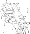
FIG. 2 shows an isometric view of an exemplary vapor compression system. -
FIG. 3 shows schematically an exemplary embodiment for a heating, ventilation and air conditioning system. -
FIG. 4 shows schematically an exemplary embodiment of a variable speed drive. -
FIG. 5 shows a schematic diagram of an exemplary permanent magnet synchronous motor. -
FIG. 6 is shows schematic diagrams of alternate exemplary rotors of an internal PMSM (IPM). -
FIG. 7 shows an exemplary transfer function for estimating flux in a permanent magnet synchronous motor. -
FIG. 1 shows an exemplary environment for a heating, ventilation and air conditioning (HVAC)system 10 in abuilding 12 for a typical commercial setting.System 10 can include avapor compression system 14 that can supply a chilled liquid which may be used to coolbuilding 12.System 10 can include aboiler 16 to supply a heated liquid that may be used to heatbuilding 12, and an air distribution system which circulates air throughbuilding 12. The air distribution system can also include anair return duct 18, anair supply duct 20 and anair handler 22.Air handler 22 can include a heat exchanger that is connected toboiler 16 andvapor compression system 14 byconduits 24. The heat exchanger inair handler 22 may receive either heated liquid fromboiler 16 or chilled liquid fromvapor compression system 14, depending on the mode of operation ofsystem 10.System 10 is shown with a separate air handler on each floor ofbuilding 12, but it is appreciated that the components may be shared between or among floors. -
FIGS. 2 and3 show an exemplaryvapor compression system 14 that can be used inHVAC system 10.Vapor compression system 14 can circulate a refrigerant through a circuit starting withcompressor 32 and including acondenser 34, expansion valve(s) or device(s) 36, and an evaporator orliquid chiller 38.Vapor compression system 14 can also include acontrol panel 40 that can include an analog to digital (A/D)converter 42, amicroprocessor 44, anon-volatile memory 46, and aninterface board 48. Some examples of fluids that may be used as refrigerants invapor compression system 14 are hydrofluorocarbon (HFC) based refrigerants, for example, R-410A, R-407, R-134a, hydrofluoro olefin (HFO), "natural" refrigerants like ammonia (NH3), R-717, carbon dioxide (CO2), R-744, or hydrocarbon based refrigerants, water vapor or any other suitable type of refrigerant. -
Motor 50 used withcompressor 32 can be powered by a variable speed drive (VSD) 52 or can be powered directly from an alternating current (AC) or direct current (DC) power source.Motor 50 can include any type of PMSM that can be powered by a VSD or directly from an AC or DC power source. -
FIG. 4 shows an exemplary embodiment of a VSD.VSD 52 receives AC power having a particular fixed line voltage and fixed line frequency from an AC power source and provides AC power tomotor 50 at a desired voltage and desired frequency, both of which can be varied to satisfy particular requirements.VSD 52 can have three components: a rectifier/converter 222, aDC link 224 and aninverter 226. The rectifier/converter 222 converts the fixed frequency, fixed magnitude AC voltage from the AC power source into DC voltage. The DC link 224 filters the DC power from theconverter 222 and provides energy storage components such as capacitors and/or inductors. Finally,inverter 226 converts the DC voltage from DC link 224 into variable frequency, variable magnitude AC voltage formotor 50. - In an exemplary embodiment, the rectifier/
converter 222 may be a three-phase pulse width modulated boost rectifier having insulated gate bipolar transistors to provide a boosted DC voltage to the DC link 224 to obtain a maximum RMS output voltage fromVSD 52 greater than the input voltage toVSD 52. Alternately, theconverter 222 may be a passive diode or thyristor rectifier without voltage-boosting capability. -
VSD 52 can provide a variable magnitude output voltage and variable frequency tomotor 50, to permit effective operation ofmotor 50 in response to a particular load conditions.Control panel 40 can provide control signals toVSD 52 to operate theVSD 52 andmotor 50 at appropriate operational settings for the particular sensor readings received bycontrol panel 40. For example,control panel 40 can provide control signals toVSD 52 to adjust the output voltage and output frequency provided byVSD 52 in response to changing conditions invapor compression system 14, i.e.,control panel 40 can provide instructions to increase or decrease the output voltage and output frequency provided byVSD 52 in response to increasing or decreasing load conditions oncompressor 32. The estimated rotor phase angle θr and rotor frequency ω r, ofmotor 50, as described in more detail below, may be input to the control panel for feedback control of the position and rotational frequency ofmotor 50. -
Compressor 32 compresses a refrigerant vapor and delivers the vapor to condenser 34 through a discharge passage. In one exemplary embodiment,compressor 32 can be a centrifugal compressor having one or more compression stages. The refrigerant vapor delivered bycompressor 32 tocondenser 34 transfers heat to a fluid, for example, water or air. The refrigerant vapor condenses to a refrigerant liquid incondenser 34 as a result of the heat transfer with the fluid. The liquid refrigerant fromcondenser 34 flows throughexpansion device 36 toevaporator 38. A hot gas bypass valve (HGBV) 134 may be connected in a separate line extending from compressor discharge to compressor suction. In the exemplary embodiment shown inFIG. 3 ,condenser 34 is water cooled and includes atube bundle 54 connected to acooling tower 56. - The liquid refrigerant delivered to
evaporator 38 absorbs heat from another fluid, which may or may not be the same type of fluid used forcondenser 34, and undergoes a phase change to a refrigerant vapor. In the exemplary embodiment shown inFIG. 3 ,evaporator 38 includes atube bundle 60 having asupply line 60S and areturn line 60R connected to acooling load 62. A process fluid, for example, water, ethylene glycol, calcium chloride brine, sodium chloride brine, or any other suitable liquid, entersevaporator 38 viareturn line 60R and exitsevaporator 38 viasupply line 60S.Evaporator 38 lowers the temperature of the process fluid in the tubes. Thetube bundle 60 inevaporator 38 can include a plurality of tubes and a plurality of tube bundles. The vapor refrigerant exitsevaporator 38 and returns tocompressor 32 by a suction line to complete the circuit or cycle. In an exemplary embodiment,vapor compression system 14 may use one or more of each of variable speed drive (VSD) 52,motor 50,compressor 32,condenser 34,expansion valve 36 and/orevaporator 38 in one or more refrigerant circuits. - The control method described with respect to
FIG. 7 below provides a compensation method for estimating a flux in a permanent magnet synchronous motor to reduce the estimation error due to the unavoidable dc shift from voltage and current measurements and an error coefficient or correction variable a. The method includes the steps of adjusting the value of an error correction variable at selected intervals; changing the value of error correction variable as a function of a speed of a rotor of the PMSM; applying a first value of the error correction variable that is configured to obtain faster convergence over a predetermined initial motor starting interval; and applying a second value of the error correction variable after the predetermined initial motor starting interval, the second value configured to reduce an error in the flux estimation. In addition, the compensation method reduces the estimation error due to the error correction variable a. An estimated flux linkage includes a real component alpha and an imaginary component beta. The alpha and beta components of the estimated flux linkage may be used to compensate for the error due to the error correction variable a. - Referring to
FIG. 5 , anexemplary PMSM 86 includes astator portion 72. Thestator portion 72 can be configured substantially similar to a stator of a conventional induction motor.Stator portion 72 includes a plurality ofwindings 74 disposed inslots 25 defined by a plurality ofteeth 17, symmetrically distributed about an inside radius ofstator portion 72 adjacent to arotor portion 70.Rotor portion 70 is positioned axially concentrically with and insidestator portion 72.Rotor portion 70 andstator portion 72 are separated by anair gap 68.Rotor portion 70 may include a cylindrical steel rotor frame or cage 31 with a plurality ofpermanent magnets 84 arranged peripherally on rotor cage 31.Permanent magnets 84 produce a magnetic field inair gap 68. -
Permanent magnets 84 may be positioned or arranged to provide multiple pole arrangements or configurations, for example 2-pole or 4-pole (see, e.g.,FIGS. 6A and 6B ), inrotor portion 70.Permanent magnets 84 may be adhesively affixed to cage 31, and are enveloped by asleeve 29 to maintainpermanent magnets 84 on cage 31 when centrifugal forces act onrotor portion 70 during rotation ofPMSM 86.Sleeve 29 may be constructed of carbon fiber tubular sheet material, stainless steel or other similarly flexible, high strength, magnetically non-permeable material.Air gap 68 is small relative to an effective air gap g shown between opposingarrows 45. Effective air gap g includes the height h ofpermanent magnets 84 andsleeve 29. - Referring next to
FIG. 7 , in an exemplary method of flux estimation in a PMSM, a low-pass filter is used to obtain the estimated flux. The transfer function of the low pass filter is represented by equation 1:
- s represents an S-domain integration operation of the low-pass filter; and
- a = the error correction variable for the low-pass filter.
- In one embodiment, the low pass filter represented by the transfer function may be implemented in software. Alternately, the low pass filter may be implemented in hardware components, e.g., integrated circuit, ASIC, or R-L-C circuit. By increasing the value of variable a in
Equation 1 the convergence of the estimated flux can occur in a shorter time interval, but the error in the estimated flux will be greater. By decreasing the value of the variable a convergence can occur more slowly, but with a smaller estimation error. For example, when rotor speed is 94.25 rad/s, a different "a" value yields different angle errors. - a = 2 sin ϕ = 0.9997749 angle error = 1.2167°
- a = 4 sin ϕ = 0.99910058 angle error = 2.43025°
- a = 6 sin ϕ = 0.99797971 angle error = 3.64265°
- a = 8 sin ϕ = 0.99641682 angle error = 4.851787°
- a = 10 sin ϕ= 0.99441813 angle error = 6.056610°
- An open
loop estimation method 100 is shown inFIG. 7 . An α-axis voltage ν a is applied to aninput 101 of asummation block 102. The inputs to the estimation method are motor phase currents and voltages expressed in α-β coordinate frame. The coordinate frames and voltage and current vectors of PMSM, being the phase axes a, b and c, and α-axis and β-taxis represent a fixed Cartesian coordinate frame aligned with phase a; d-axis and q-axis represent a rotating Cartesian coordinate frame aligned with rotor flux. The α-β frame expressions for α-axis and β-axis are obtained by applying a Clarke transformation to their corresponding three phase representation. - An α-axis current value ia, representing the phase a stator, or armature, current, is provided to a
current prediction model 104 which predicts the current used in the estimation. The output i a ofcurrent prediction model 104 is multiplied by stator resistance r s at block 106 to generate an estimated drop-off voltage on stator winding. The output of block 106 is then subtracted from α-axis phase a voltage ν a in summation block 102, and the output ofblock 102 is applied totransfer function block 108, represented by the transfer function ofEquation 1. Intransfer function block 108, filter variable a is introduced to achieve a minimum error at different speed ranges within a required convergence time. The output ofblock 108 is then compensated atblock 110 to reduce or remove the error introduced by a inblock 108. The output ofblock 110 is combined at summation block 112 with an output ofblock 114.Block 114 represents the stator mutual inductance L m, which is the value by which the input predicted current i a is multiplied to generate the output ofblock 114. The output ofblock 114 is subtracted from the error compensated air gap flux linkage, or output ofblock 110, atblock 112. The difference ofblocks block 112, representing the estimated rotor flux linkage in α-axis. Then the rotor phase angle θr is estimated byangle calculation block 116 using the estimated rotor flux linkage from both α and β-axis. The estimated rotorphase angle θ r 120 is applied to block 118, and the time domain derivative of the estimated rotorphase angle θ r 120 is generated at the output ofblock 117 as the rotor frequency ω r. - More precise flux estimation and control of
PMSM 86 may be achieved by adjusting the value of variable a at selected intervals. For example, the value of a may be changed as a function of the rotor speed wherein the value of a is greater initially, i.e., upon startingPMSM 86 to obtain a faster convergence at the beginning of the estimation. After the convergence, a smaller value of a is applied to reduce the error in the flux estimation. In addition, in an exemplary embodiment, the value of a may be transitioned gradually, or ramped down from the higher initial value of a to the lower value of a, to provide improved system stability. - An exemplary embodiment of the method is described as follows:
- ramp down a:
- If (ω r > 1200 and ω r < 1500)
a =5 - (ω r - 1200) * 0.01 - If (ω r> 1500)
a =2
(" a " = error correction variable)
- If (ω r > 1200 and ω r < 1500)
- A compensation method is disclosed to reduce the estimation error due to a. The estimated flux linkage includes two components, a real component alpha (α) and an imaginary component beta (β). Alpha and beta components of the estimated flux linkage may be used to compensate for the magnitude error due to the error correction variable a . The expressions of the magnitude compensation are given by the following equations:

- a is the error correction variable and
- ω r is the rotor speed.
- The second step is for the phase angle correction, in which the flux linkage complex variable includes two components, a real component alpha and an imaginary component beta, is used. Alpha and beta components of this complex variable may be used to compensate for the phase error due to the error correction variable a. The expressions of the complex variable used for phase angle correction is given as:

- If the magnitude compensation and the phase compensation are combined, the expressions of the compensation are given by the following equations:


-


- fα and fβ are the alpha components of the flux linkage before compensation; and
- ωr is the rotor speed.
- Since the ratio of the sampling frequency to the fundamental frequency is low, a relatively long delay is unavoidable without increasing the sampling frequency. Increasing the sampling frequency generally increases the cost of a control system. A current prediction method can be employed to predict the current to eliminate the effect of the sampling delay, without the need for increasing the sampling frequency. For high speed and ultra high speed applications, the sampling number per cycle becomes greatly reduced. To reduce the estimation error, the current at the Nth sampling interval may be used to predict the current at the next (N+1)th sampling interval. The predicted current may then be used to reduce the error in the flux linkage estimation. The current prediction is based on the PMSM machine model.
- An exemplary embodiment of the method is described.
- The prediction method is based on the q-d reference:
- Predicted q axis current is given as:


-


-


-


-


- ωr is the rotor speed.
-
- While the foregoing describes a control system and method for controlling a sensorless PMSM, the control system and method for estimating an angle position and speed of a motor may be applied to other types of sensorless, synchronous motors, e.g., induction-type motors, and such synchronous motors are considered to be within the scope of control system herein described and claimed.
- It should be understood that the application is not limited to the details or methodology set forth in the following description or illustrated in the figures. It should also be understood that the phraseology and terminology employed herein is for the purpose of description only and should not be regarded as limiting.
- While the exemplary embodiments illustrated in the figures and described herein are presently preferred, it should be understood that these embodiments are offered by way of example only. Accordingly, the present application is not limited to a particular embodiment, but extends to various modifications. The order or sequence of any processes or method steps may be varied or re-sequenced according to alternative embodiments.
- The present application contemplates methods, systems and program products on any machine-readable media for accomplishing its operations. The embodiments of the present application may be implemented using an existing computer processors, or by a special purpose computer processor for an appropriate system, incorporated for this or another purpose or by a hardwired system.
- It is important to note that the construction and arrangement of the flux estimation method for PMSM control as shown in the various exemplary embodiments is illustrative only. Although only a few embodiments have been described in detail in this disclosure, those who review this disclosure will readily appreciate that many modifications are possible (e.g., variations in sizes, dimensions, structures, shapes and proportions of the various elements, values of parameters, mounting arrangements, use of materials, colors, orientations, etc.) without materially departing from the novel teachings and advantages of the subject matter recited in the application. For example, elements shown as integrally formed may be constructed of multiple parts or elements, the position of elements may be reversed or otherwise varied, and the nature or number of discrete elements or positions may be altered or varied. Accordingly, all such modifications are intended to be included within the scope of the present application. The order or sequence of any process or method steps may be varied or re-sequenced according to alternative embodiments. Other substitutions, modifications, changes and omissions may be made in the design, operating conditions and arrangement of the exemplary embodiments without departing from the scope of the present application.
- As noted above, embodiments within the scope of the present application include program products comprising machine-readable media for carrying or having machine-executable instructions or data structures stored thereon. Such machine-readable media can be any available media that can be accessed by a general purpose or special purpose computer or other machine with a processor. By way of example, such machine-readable media can comprise RAM, ROM, EPROM, EEPROM, CD-ROM or other optical disk storage, magnetic disk storage or other magnetic storage devices, or any other medium which can be used to carry or store desired program code in the form of machine-executable instructions or data structures and which can be accessed by a general purpose or special purpose computer or other machine with a processor. When information is transferred or provided over a network or another communications connection (either hardwired, wireless, or a combination of hardwired or wireless) to a machine, the machine properly views the connection as a machine-readable medium. Thus, any such connection is properly termed a machine-readable medium. Combinations of the above are also included within the scope of machine-readable media. Machine-executable instructions comprise, for example, instructions and data which cause a general purpose computer, special purpose computer, or special purpose processing machines to perform a certain function or group of functions.
- It should be noted that although the figures herein may show a specific order of method steps, it is understood that the order of these steps may differ from what is depicted. Also two or more steps may be performed concurrently or with partial concurrence. Such variation will depend on the software and hardware systems chosen and on designer choice. It is understood that all such variations are within the scope of the application. Likewise, software implementations could be accomplished with standard programming techniques with rule based logic and other logic to accomplish the various connection steps, processing steps, comparison steps and decision steps.
- According to the present application, also the following embodiments are provided as examples, which embodiments are numbered for easier references:
- Embodiment 1: A method for controlling a synchronous motor by determining a rotor position of the synchronous motor by estimating a flux linkage, the method comprising:
- applying a voltage of a stator winding of the motor to a transfer function, the transfer function comprising an S-domain integration operation and an error correction variable;
- processing an output of the transfer function to compensate for the error correction variable introduced in the transfer function;
- generating an estimated flux linkage;
- computing an angle of the rotor position based on the estimated flux linkage; and
- inputting the computed rotor position to a controller for controlling a position or speed of the motor.
- Embodiment 2: The method of
embodiment 1, wherein the transfer function represents a low pass filter. - Embodiment 3: The method of
embodiment 1, further comprising predicting a stator current value at a next time interval by determining an α-axis current and a β-axis current and applying the α-axis current and the β-axis current to a current prediction model. - Embodiment 4: The method of embodiment 3, further comprising multiplying the predicted stator current value by a stator resistance value, and generating an estimated drop-off voltage on the stator winding.
- Embodiment 5: The method of embodiment 4, wherein the voltage of a stator winding is obtained by subtracting the estimated drop-off voltage from an α-axis voltage and a β-axis voltage of the stator winding.
- Embodiment 6: The method of
embodiment 1, wherein the error correction variable is selected to achieve a minimum error at multiple speed ranges within a required convergence time. - Embodiment 7: The method of
embodiment 1, wherein the processing an output of the transfer function to compensate for the error correction variable introduced in the transfer function comprises:- compensating to reduce or remove an error introduced by the error correction variable to obtain a flux linkage generated by a rotor of the motor.
- Embodiment 8: The method of
embodiment 1, wherein generating an estimated flux linkage comprises:- computing an estimated flux linkage by multiplying a stator mutual inductance value by a predicted stator current and subtracting the multiplied stator mutual inductance from the estimated flux linkage to generate an estimated rotor flux linkage.
- Embodiment 9: The method of embodiment 8, further comprising estimating a rotor phase angle based on the estimated flux linkage from both α and β-axis; and generating a rotor frequency as a time domain derivative of the estimated rotor phase angle.
- Embodiment 10: The method of
embodiment 1, wherein the transfer function is expressed as
- Embodiment 11: The method of
embodiment 1, wherein the processing an output of the transfer function further comprises using a compensation algorithm comprising an alpha component and a beta component of the estimated flux linkage to compensate for the error due to the error correction variable, wherein the magnitude compensation algorithm is expressed by:
- a is the error correction variable and
- ωr is a rotor speed.
- Embodiment 12: The method of embodiment 11, wherein a flux linkage complex variable includes a real component and an imaginary component, the flux linkage complex variable being employed to compensate for a phase error due to the error correction variable, the flux linkage complex variable expressed by:

- Embodiment 13: The method of
embodiment 12, further comprising combining a magnitude compensation and a phase compensation, the combination of magnitude compensation and the phase compensation determined by the following equations:

-


- fα and fβ are the alpha component and the beta component of the flux linkage before compensation; and
- ω r is the rotor speed.
-
- Embodiment 14: The method of
embodiment 1, further comprising:- determining a stator current value and the stator winding voltage at an Nth sampling interval;
- predicting the stator current value at an N+1th sampling interval based on the determined stator current value and the stator winding voltage at the Nth sampling interval; and
- applying the predicted stator current value at the N+1th sampling interval to reduce the error in the estimated flux linkage.
- Embodiment 15: The method of
embodiment 1, further comprising:- changing the value of error correction variable as a function of a speed of a rotor of the motor;
- applying a first value of the error correction variable that is configured to obtain faster convergence over a predetermined initial motor starting interval; and
- applying a second value of the error correction variable after the predetermined initial motor starting interval, the second value configured to reduce an error in the flux estimation.
- Embodiment 16: A chiller system comprising:
- a compressor, a condenser, and an evaporator connected in a closed refrigerant loop;
- a synchronous motor connected to the compressor to power the compressor; and
- a variable speed drive connected to the motor, the variable speed drive being configured to receive an input AC power at a fixed input AC voltage and a fixed input frequency and provide an output power at a variable voltage and variable frequency to the motor, the variable speed drive comprising:
- a converter connectable to an AC power source providing the input AC voltage, the converter being configured to convert the input AC voltage to a DC voltage;
- a DC link connected to the converter, the DC link being configured to filter and store the DC voltage from the converter stage; and
- an inverter connected to the DC link; and
- a controller configured to control a rotor speed of the synchronous motor based on a rotor angle from an estimated flux linkage.
- Embodiment 17: The system of
embodiment 16, wherein the controller is configured to:- apply a voltage of a stator winding of the motor to a transfer function, the transfer function comprising an S-domain integration operation and an error correction variable;
- process an output of the transfer function to compensate for the error correction variable introduced in the transfer function;
- generate an estimated flux linkage;
- compute an angle of the rotor position based on the estimated flux linkage; and
- input the computed rotor position to the controller.
- Embodiment 18: The system of
embodiment 17, wherein the transfer function is expressed as:
- Embodiment 19: The system of
embodiment 17, further comprising a compensation algorithm, the compensation algorithm comprising an alpha component and a beta component of the estimated flux linkage to compensate for an error due to the error correction variable, wherein the magnitude compensation algorithm is expressed by: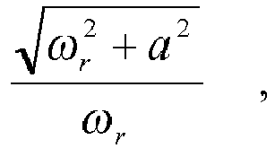
- a is the error correction variable and
- ωr is a rotor speed.
- Embodiment 20: The system of embodiment 19, wherein a flux linkage complex variable includes a real component and an imaginary component, the flux linkage complex variable is employed to compensate for a phase error due to the error correction variable, the complex variable used for phase angle correction is expressed by:

- Embodiment 21: The method of
embodiment 17, wherein magnitude compensation and phase compensation are combined, the combination of the magnitude compensation and the phase compensation are expressed by:

-


- fα and fβ are the alpha and beta components of the flux linkage before compensation; and
- ωr is the rotor speed.
-
Claims (20)
- A chiller system comprising:a compressor configured to circulate a refrigerant between an evaporator and a condenser in a closed refrigerant loop;a synchronous motor configured to drive the compressor, the motor comprising a stator winding and a rotor; anda controller configured to estimate a flux linkage of the rotor by:wherein the controller is configured to provide a control signal to the motor based on the estimated flux linkage.applying a voltage of the stator winding to a transfer function comprising an S-domain integration operation and an error correction variable;using a first value of the error correction variable in the transfer function to obtain convergence of the flux linkage over an initial motor starting interval; andupdating the transfer function to replace the first value of the error correction variable with a second value of the error correction variable after the initial motor starting interval to reduce a flux linkage estimation error resulting from the error correction variable;
- The chiller system of Claim 1, wherein:the first value of the error correction variable is greater than the second value of the error correction variable; andupdating the transfer function comprises reducing the error correction variable from the first value to the second value.
- The chiller system of Claim 2, wherein reducing the error correction variable comprises gradually ramping-down the error correction variable from the first value to the second value.
- The chiller system of Claim 1, wherein the initial motor starting interval is defined by a speed of the motor such that the initial motor starting interval ends when the motor reaches a predetermined motor speed.
- The chiller system of Claim 1, wherein the controller is configured to:determine a position of the rotor based on the estimated flux linkage; andgenerate the control signal for the motor based on the position of the rotor.
- The chiller system of Claim 1, wherein estimating the flux linkage further comprises processing an output of the transfer function to compensate for the flux linkage estimation error resulting from the error correction variable.
- The chiller system of Claim 1, wherein the controller is configured to select the first value of the error correction variable to achieve a minimum value for the flux linkage estimation error while obtaining convergence of the estimated flux linkage within the initial motor starting interval.
- The chiller system of Claim 1, wherein the controller is configured to:determine the voltage of the stator winding and an electric current of the stator winding during a first sampling interval;predict the electric current of the stator winding during a next sampling interval based on the determined voltage of the stator winding and the electric current of the stator winding during the first sampling interval; andapply the predicted electric current of the stator winding during the next sampling interval to reduce the flux linkage estimation error.
- The chiller system of Claim 8, wherein the controller is configured to:predict the electric current of the stator winding during the next sampling interval based on a determined α-axis current and a determined β-taxis current; andapply the determined α-axis current and the determined β-axis current to a current prediction model.
- The chiller system of Claim 1, further comprising a variable speed drive connected to the motor and configured to:receive an input AC power at a fixed input AC voltage and a fixed input frequency; andprovide an output power at a variable voltage and variable frequency to the motor.
- The chiller system of Claim 10, wherein the variable speed drive comprises:a converter connectable to an AC power source providing the input AC voltage, the converter being configured to convert the input AC voltage to a DC voltage;a DC link connected to the converter, the DC link being configured to filter and store the DC voltage from the converter stage; andan inverter connected to the DC link.
- A method for controlling a synchronous motor having a stator winding and a rotor, the method comprising:applying a voltage of the stator winding to a transfer function comprising an S-domain integration operation and an error correction variable;using a first value of the error correction variable in the transfer function to obtain convergence of a flux linkage of the motor over an initial motor starting interval;updating the transfer function to replace the first value of the error correction variable with a second value of the error correction variable after the initial motor starting interval to reduce a flux linkage estimation error resulting from the error correction variable;estimating the flux linkage of the rotor using the transfer function;providing a control signal to the motor based on the estimated flux linkage; andusing the control signal to operate the motor by adjusting a speed or position of the motor based on the control signal.
- The method of Claim 12, wherein:the first value of the error correction variable is greater than the second value of the error correction variable; andupdating the transfer function comprises reducing the error correction variable from the first value to the second value.
- The method of Claim 13, wherein reducing the error correction variable comprises gradually ramping-down the error correction variable from the first value to the second value.
- The method of Claim 12, wherein the initial motor starting interval is defined by a speed of the motor such that the initial motor starting interval ends when the motor reaches a predetermined motor speed.
- The method of Claim 12, further comprising:determining a position of the rotor based on the estimated flux linkage; andgenerating the control signal for the motor based on the position of the rotor.
- The method of Claim 12, wherein estimating the flux linkage comprises processing an output of the transfer function to compensate for the flux linkage estimation error resulting from the error correction variable.
- The method of Claim 12, further comprising selecting the first value of the error correction variable to achieve a minimum value for the flux linkage estimation error while obtaining convergence of the estimated flux linkage within the initial motor starting interval.
- The method of Claim 12, further comprising:determining the voltage of the stator winding and an electric current of the stator winding during a first sampling interval;predicting the electric current of the stator winding during a next sampling interval based on the determined voltage of the stator winding and the electric current of the stator winding during the first sampling interval; andapplying the predicted electric current of the stator winding during the next sampling interval to reduce the error in estimating the flux linkage.
- The method of Claim 19, further comprising:predicting the electric current of the stator winding during the next sampling interval based on a determined α-axis current and a determined β-taxis current; andapplying the determined α-axis current and the determined β-axis current to a current prediction model.
Applications Claiming Priority (3)
| Application Number | Priority Date | Filing Date | Title |
|---|---|---|---|
| US31142010P | 2010-03-08 | 2010-03-08 | |
| PCT/US2011/026045 WO2011112363A2 (en) | 2010-03-08 | 2011-02-24 | Method and system for controlling a permanent magnet synchronous motor |
| EP11708614.0A EP2545642B1 (en) | 2010-03-08 | 2011-02-24 | Method and system for controlling a permanent magnet synchronous motor |
Related Parent Applications (1)
| Application Number | Title | Priority Date | Filing Date |
|---|---|---|---|
| EP11708614.0A Division EP2545642B1 (en) | 2010-03-08 | 2011-02-24 | Method and system for controlling a permanent magnet synchronous motor |
Publications (3)
| Publication Number | Publication Date |
|---|---|
| EP3154183A2 true EP3154183A2 (en) | 2017-04-12 |
| EP3154183A3 EP3154183A3 (en) | 2017-11-15 |
| EP3154183B1 EP3154183B1 (en) | 2020-09-09 |
Family
ID=44564059
Family Applications (2)
| Application Number | Title | Priority Date | Filing Date |
|---|---|---|---|
| EP16194425.1A Active EP3154183B1 (en) | 2010-03-08 | 2011-02-24 | Method and system for controlling a permanent magnet synchronous motor |
| EP11708614.0A Active EP2545642B1 (en) | 2010-03-08 | 2011-02-24 | Method and system for controlling a permanent magnet synchronous motor |
Family Applications After (1)
| Application Number | Title | Priority Date | Filing Date |
|---|---|---|---|
| EP11708614.0A Active EP2545642B1 (en) | 2010-03-08 | 2011-02-24 | Method and system for controlling a permanent magnet synchronous motor |
Country Status (7)
| Country | Link |
|---|---|
| US (4) | US9490733B2 (en) |
| EP (2) | EP3154183B1 (en) |
| JP (1) | JP2013523065A (en) |
| KR (2) | KR101534518B1 (en) |
| CN (2) | CN102792580B (en) |
| TW (1) | TWI505630B (en) |
| WO (1) | WO2011112363A2 (en) |
Cited By (1)
| Publication number | Priority date | Publication date | Assignee | Title |
|---|---|---|---|---|
| CN106160615A (en) * | 2016-08-03 | 2016-11-23 | 珠海格力节能环保制冷技术研究中心有限公司 | Electric machine control system, compressor and motor heating starting method |
Families Citing this family (23)
| Publication number | Priority date | Publication date | Assignee | Title |
|---|---|---|---|---|
| KR101534518B1 (en) * | 2010-03-08 | 2015-07-07 | 존슨 컨트롤스 테크놀러지 컴퍼니 | Method and system for controlling a permagnent magnet synchronous motor |
| FR2984637B1 (en) * | 2011-12-20 | 2013-11-29 | IFP Energies Nouvelles | METHOD FOR DETERMINING THE POSITION AND SPEED OF A ROTOR OF A SYNCHRONOUS ELECTRIC MACHINE |
| JP6511224B2 (en) * | 2014-04-23 | 2019-05-15 | 日立オートモティブシステムズ株式会社 | Power supply |
| KR101840509B1 (en) | 2014-04-29 | 2018-03-20 | 엘에스산전 주식회사 | Rotation angle estimation module for sensorless vector control of PMSM |
| JP6375757B2 (en) * | 2014-07-29 | 2018-08-22 | 株式会社安川電機 | Electric motor control device, electric motor magnetic flux estimation device, and electric motor magnetic flux estimation method |
| CN104791953B (en) * | 2015-04-16 | 2017-10-13 | 广东美的制冷设备有限公司 | The control method of compressor electric motor, control device in air conditioner and air conditioner |
| JP6436114B2 (en) * | 2016-02-19 | 2018-12-12 | 株式会社豊田自動織機 | Permanent magnet rotating electric machine |
| US10960922B2 (en) * | 2017-01-31 | 2021-03-30 | Steering Solutions Ip Holding Corporation | Fault tolerant field oriented control for electric power steering |
| US11994833B2 (en) | 2017-02-10 | 2024-05-28 | Johnson Controls Technology Company | Building smart entity system with agent based data ingestion and entity creation using time series data |
| US10452043B2 (en) | 2017-02-10 | 2019-10-22 | Johnson Controls Technology Company | Building management system with nested stream generation |
| US10169486B2 (en) | 2017-02-10 | 2019-01-01 | Johnson Controls Technology Company | Building management system with timeseries processing |
| US11307538B2 (en) | 2017-02-10 | 2022-04-19 | Johnson Controls Technology Company | Web services platform with cloud-eased feedback control |
| US10515098B2 (en) | 2017-02-10 | 2019-12-24 | Johnson Controls Technology Company | Building management smart entity creation and maintenance using time series data |
| KR102290819B1 (en) * | 2017-02-27 | 2021-08-17 | 도시바 미쓰비시덴키 산교시스템 가부시키가이샤 | controller |
| JP6629814B2 (en) * | 2017-10-19 | 2020-01-15 | ファナック株式会社 | Motor control device |
| CN108471198B (en) * | 2018-04-26 | 2023-07-28 | 北京建筑大学 | Control method, device and system for switched reluctance motor and controller |
| US11305784B2 (en) * | 2019-12-30 | 2022-04-19 | Karma Automotive Llc | Method for online direct estimation and compensation of flux and torque errors in electric drives |
| US11196371B2 (en) | 2020-01-10 | 2021-12-07 | DRiV Automotive Inc. | Sensorless position detection for electric motor |
| WO2022215232A1 (en) * | 2021-04-08 | 2022-10-13 | 三菱電機株式会社 | Abnormality diagnosis device and abnormality diagnosis method |
| JP7649196B2 (en) * | 2021-05-14 | 2025-03-19 | 株式会社日立産機システム | Power Conversion Equipment |
| EP4401300A1 (en) * | 2023-01-13 | 2024-07-17 | Abb Schweiz Ag | Rotor-to-stator reduction factor evaluation for externally-excited synchronous machines |
| US12398717B2 (en) * | 2023-02-09 | 2025-08-26 | Haier Us Appliance Solutions, Inc. | Single phase field oriented control for a linear compressor |
| US12553432B1 (en) * | 2025-03-11 | 2026-02-17 | Haier Us Appliance Solutions, Inc. | Dynamic flux weakening for a single phase linear compressor |
Family Cites Families (21)
| Publication number | Priority date | Publication date | Assignee | Title |
|---|---|---|---|---|
| US5334923A (en) * | 1990-10-01 | 1994-08-02 | Wisconsin Alumni Research Foundation | Motor torque control method and apparatus |
| JPH05204461A (en) * | 1991-09-26 | 1993-08-13 | Toyoda Mach Works Ltd | Digital servo control device |
| US6731083B2 (en) | 1998-06-02 | 2004-05-04 | Switched Reluctance Drives, Ltd. | Flux feedback control system |
| US6552509B2 (en) * | 2000-05-10 | 2003-04-22 | Gti Electroproject B.V. | Method and a device for sensorless estimating the relative angular position between the stator and rotor of a three-phase synchronous motor |
| US7180263B2 (en) * | 2000-11-09 | 2007-02-20 | Daikin Industries, Ltd. | Synchronous motor control method and device |
| JP4367130B2 (en) * | 2001-09-29 | 2009-11-18 | ダイキン工業株式会社 | Phase current detection method, inverter control method, motor control method, and devices thereof |
| SG149688A1 (en) * | 2002-02-25 | 2009-02-27 | Daikin Ind Ltd | Motor control method and its apparatus |
| TW594685B (en) | 2002-04-26 | 2004-06-21 | Elan Microelectronics Corp | Automatic regulation encoding/decoding device of code length and method thereof |
| US7006338B2 (en) * | 2002-09-23 | 2006-02-28 | Siemens Energy & Automation, Inc. | System and method for individual phase motor over voltage protection |
| FI114420B (en) * | 2002-10-18 | 2004-10-15 | Abb Oy | Procedure in conjunction with flour order number flux detectors for short-circuit motors without sensors |
| JP2004215318A (en) * | 2002-12-26 | 2004-07-29 | Aisin Aw Co Ltd | Apparatus and method for motor operated drive controlling and its program |
| US7265507B1 (en) * | 2006-02-20 | 2007-09-04 | Hamilton Sundstrand Corporation | Angular position and velocity estimation for synchronous machines based on extended rotor flux |
| JP5170505B2 (en) * | 2007-02-07 | 2013-03-27 | 株式会社ジェイテクト | Motor control device |
| WO2008137276A1 (en) * | 2007-05-08 | 2008-11-13 | Johnson Controls Technology Company | Variable speed drive |
| CN101369797A (en) * | 2007-08-13 | 2009-02-18 | 海信(北京)电器有限公司 | Vector control circuit and control method of electric motor |
| TWI437167B (en) * | 2007-10-31 | 2014-05-11 | Johnson Controls Tech Co | Control system |
| CN101286725A (en) * | 2008-04-17 | 2008-10-15 | 戴政 | Deriving method of motor rotative velocity and location of rotor in synchronous electric machine vector control system |
| JP2009268267A (en) | 2008-04-25 | 2009-11-12 | Sanyo Electric Co Ltd | Motor controller and generator controller |
| US8336323B2 (en) | 2008-10-03 | 2012-12-25 | Johnson Controls Technology Company | Variable speed drive with pulse-width modulated speed control |
| JP2011125107A (en) * | 2009-12-09 | 2011-06-23 | Sanyo Electric Co Ltd | Motor control device, motor drive system, and inverter control device |
| KR101534518B1 (en) * | 2010-03-08 | 2015-07-07 | 존슨 컨트롤스 테크놀러지 컴퍼니 | Method and system for controlling a permagnent magnet synchronous motor |
-
2011
- 2011-02-24 KR KR1020127026194A patent/KR101534518B1/en not_active Expired - Fee Related
- 2011-02-24 CN CN201180012731.2A patent/CN102792580B/en active Active
- 2011-02-24 JP JP2012557075A patent/JP2013523065A/en active Pending
- 2011-02-24 CN CN201610086180.9A patent/CN105591583B/en active Active
- 2011-02-24 US US13/579,464 patent/US9490733B2/en active Active
- 2011-02-24 EP EP16194425.1A patent/EP3154183B1/en active Active
- 2011-02-24 EP EP11708614.0A patent/EP2545642B1/en active Active
- 2011-02-24 WO PCT/US2011/026045 patent/WO2011112363A2/en not_active Ceased
- 2011-02-24 KR KR1020147030461A patent/KR101554886B1/en not_active Expired - Fee Related
- 2011-03-04 TW TW100107369A patent/TWI505630B/en not_active IP Right Cessation
-
2016
- 2016-03-31 US US15/088,095 patent/US9979332B2/en active Active
- 2016-03-31 US US15/088,092 patent/US9941825B2/en active Active
- 2016-03-31 US US15/088,096 patent/US9923497B2/en active Active
Non-Patent Citations (1)
| Title |
|---|
| None |
Cited By (1)
| Publication number | Priority date | Publication date | Assignee | Title |
|---|---|---|---|---|
| CN106160615A (en) * | 2016-08-03 | 2016-11-23 | 珠海格力节能环保制冷技术研究中心有限公司 | Electric machine control system, compressor and motor heating starting method |
Also Published As
| Publication number | Publication date |
|---|---|
| US20160218651A1 (en) | 2016-07-28 |
| US9941825B2 (en) | 2018-04-10 |
| JP2013523065A (en) | 2013-06-13 |
| KR101534518B1 (en) | 2015-07-07 |
| WO2011112363A3 (en) | 2012-07-26 |
| US20130141024A1 (en) | 2013-06-06 |
| CN105591583A (en) | 2016-05-18 |
| WO2011112363A2 (en) | 2011-09-15 |
| US9923497B2 (en) | 2018-03-20 |
| US9979332B2 (en) | 2018-05-22 |
| EP3154183A3 (en) | 2017-11-15 |
| EP2545642B1 (en) | 2016-10-19 |
| US20160218653A1 (en) | 2016-07-28 |
| CN102792580A (en) | 2012-11-21 |
| CN102792580B (en) | 2016-01-13 |
| TWI505630B (en) | 2015-10-21 |
| TW201206049A (en) | 2012-02-01 |
| KR20120136385A (en) | 2012-12-18 |
| US9490733B2 (en) | 2016-11-08 |
| CN105591583B (en) | 2019-06-28 |
| KR20140137460A (en) | 2014-12-02 |
| KR101554886B1 (en) | 2015-09-24 |
| EP3154183B1 (en) | 2020-09-09 |
| US20160218654A1 (en) | 2016-07-28 |
| EP2545642A2 (en) | 2013-01-16 |
Similar Documents
| Publication | Publication Date | Title |
|---|---|---|
| US9979332B2 (en) | Motor control system and method with flux linkage estimation error compensation | |
| US9954473B2 (en) | Motor driving apparatus and home appliance including the same | |
| CN109478865B (en) | Motor drive device, refrigerator, and air conditioner | |
| CN109314484B (en) | Motor system, motor drive device, refrigeration cycle device, and air conditioner | |
| CN102457225A (en) | Refrigerating apparatus and controller for permanent magnet synchronous motor | |
| CN101946136B (en) | Refrigeration equipment | |
| JP4744505B2 (en) | Motor drive control device, motor drive control method and coordinate conversion method, ventilation fan, liquid pump, blower, refrigerant compressor, air conditioner, and refrigerator | |
| KR101770425B1 (en) | Refrigerator and controlling method thereof | |
| JP7237746B2 (en) | Open winding motor drive device and refrigeration cycle device | |
| TWI662782B (en) | Motor driving device, refrigeration cycle device including the same, and motor driving method | |
| KR102010388B1 (en) | Power converting apparatus and air conditioner including the same | |
| JP6846939B2 (en) | Motor control device, rotary compressor system and motor control method | |
| JP7217833B1 (en) | Motor drive device, electrical constant measurement method and refrigeration equipment | |
| US11984827B2 (en) | Motor control apparatus, motor, compressor, refrigeration apparatus and vehicle | |
| KR102080519B1 (en) | Motor driving device and air conditioner including the same |
Legal Events
| Date | Code | Title | Description |
|---|---|---|---|
| PUAI | Public reference made under article 153(3) epc to a published international application that has entered the european phase |
Free format text: ORIGINAL CODE: 0009012 |
|
| STAA | Information on the status of an ep patent application or granted ep patent |
Free format text: STATUS: THE APPLICATION HAS BEEN PUBLISHED |
|
| AC | Divisional application: reference to earlier application |
Ref document number: 2545642 Country of ref document: EP Kind code of ref document: P |
|
| AK | Designated contracting states |
Kind code of ref document: A2 Designated state(s): AL AT BE BG CH CY CZ DE DK EE ES FI FR GB GR HR HU IE IS IT LI LT LU LV MC MK MT NL NO PL PT RO RS SE SI SK SM TR |
|
| RAP1 | Party data changed (applicant data changed or rights of an application transferred) |
Owner name: JOHNSON CONTROLS TECHNOLOGY COMPANY |
|
| PUAL | Search report despatched |
Free format text: ORIGINAL CODE: 0009013 |
|
| AK | Designated contracting states |
Kind code of ref document: A3 Designated state(s): AL AT BE BG CH CY CZ DE DK EE ES FI FR GB GR HR HU IE IS IT LI LT LU LV MC MK MT NL NO PL PT RO RS SE SI SK SM TR |
|
| RIC1 | Information provided on ipc code assigned before grant |
Ipc: H02P 21/14 20160101ALI20171012BHEP Ipc: H02P 25/03 20160101ALI20171012BHEP Ipc: H02P 6/185 20160101ALI20171012BHEP Ipc: H02P 21/06 20160101ALI20171012BHEP Ipc: H02P 25/024 20160101ALI20171012BHEP Ipc: H02P 1/52 20060101ALI20171012BHEP Ipc: H02P 6/18 20160101AFI20171012BHEP Ipc: H02P 23/14 20060101ALI20171012BHEP Ipc: H02P 25/02 20160101ALI20171012BHEP |
|
| STAA | Information on the status of an ep patent application or granted ep patent |
Free format text: STATUS: REQUEST FOR EXAMINATION WAS MADE |
|
| 17P | Request for examination filed |
Effective date: 20180430 |
|
| RBV | Designated contracting states (corrected) |
Designated state(s): AL AT BE BG CH CY CZ DE DK EE ES FI FR GB GR HR HU IE IS IT LI LT LU LV MC MK MT NL NO PL PT RO RS SE SI SK SM TR |
|
| STAA | Information on the status of an ep patent application or granted ep patent |
Free format text: STATUS: EXAMINATION IS IN PROGRESS |
|
| 17Q | First examination report despatched |
Effective date: 20180920 |
|
| GRAP | Despatch of communication of intention to grant a patent |
Free format text: ORIGINAL CODE: EPIDOSNIGR1 |
|
| STAA | Information on the status of an ep patent application or granted ep patent |
Free format text: STATUS: GRANT OF PATENT IS INTENDED |
|
| INTG | Intention to grant announced |
Effective date: 20190923 |
|
| GRAJ | Information related to disapproval of communication of intention to grant by the applicant or resumption of examination proceedings by the epo deleted |
Free format text: ORIGINAL CODE: EPIDOSDIGR1 |
|
| STAA | Information on the status of an ep patent application or granted ep patent |
Free format text: STATUS: EXAMINATION IS IN PROGRESS |
|
| GRAP | Despatch of communication of intention to grant a patent |
Free format text: ORIGINAL CODE: EPIDOSNIGR1 |
|
| STAA | Information on the status of an ep patent application or granted ep patent |
Free format text: STATUS: GRANT OF PATENT IS INTENDED |
|
| INTC | Intention to grant announced (deleted) | ||
| INTG | Intention to grant announced |
Effective date: 20200318 |
|
| GRAS | Grant fee paid |
Free format text: ORIGINAL CODE: EPIDOSNIGR3 |
|
| GRAA | (expected) grant |
Free format text: ORIGINAL CODE: 0009210 |
|
| STAA | Information on the status of an ep patent application or granted ep patent |
Free format text: STATUS: THE PATENT HAS BEEN GRANTED |
|
| AC | Divisional application: reference to earlier application |
Ref document number: 2545642 Country of ref document: EP Kind code of ref document: P |
|
| AK | Designated contracting states |
Kind code of ref document: B1 Designated state(s): AL AT BE BG CH CY CZ DE DK EE ES FI FR GB GR HR HU IE IS IT LI LT LU LV MC MK MT NL NO PL PT RO RS SE SI SK SM TR |
|
| REG | Reference to a national code |
Ref country code: GB Ref legal event code: FG4D |
|
| REG | Reference to a national code |
Ref country code: AT Ref legal event code: REF Ref document number: 1312811 Country of ref document: AT Kind code of ref document: T Effective date: 20200915 Ref country code: CH Ref legal event code: EP |
|
| REG | Reference to a national code |
Ref country code: DE Ref legal event code: R096 Ref document number: 602011068582 Country of ref document: DE |
|
| REG | Reference to a national code |
Ref country code: IE Ref legal event code: FG4D |
|
| REG | Reference to a national code |
Ref country code: LT Ref legal event code: MG4D |
|
| PG25 | Lapsed in a contracting state [announced via postgrant information from national office to epo] |
Ref country code: NO Free format text: LAPSE BECAUSE OF FAILURE TO SUBMIT A TRANSLATION OF THE DESCRIPTION OR TO PAY THE FEE WITHIN THE PRESCRIBED TIME-LIMIT Effective date: 20201209 Ref country code: FI Free format text: LAPSE BECAUSE OF FAILURE TO SUBMIT A TRANSLATION OF THE DESCRIPTION OR TO PAY THE FEE WITHIN THE PRESCRIBED TIME-LIMIT Effective date: 20200909 Ref country code: GR Free format text: LAPSE BECAUSE OF FAILURE TO SUBMIT A TRANSLATION OF THE DESCRIPTION OR TO PAY THE FEE WITHIN THE PRESCRIBED TIME-LIMIT Effective date: 20201210 Ref country code: SE Free format text: LAPSE BECAUSE OF FAILURE TO SUBMIT A TRANSLATION OF THE DESCRIPTION OR TO PAY THE FEE WITHIN THE PRESCRIBED TIME-LIMIT Effective date: 20200909 Ref country code: BG Free format text: LAPSE BECAUSE OF FAILURE TO SUBMIT A TRANSLATION OF THE DESCRIPTION OR TO PAY THE FEE WITHIN THE PRESCRIBED TIME-LIMIT Effective date: 20201209 Ref country code: LT Free format text: LAPSE BECAUSE OF FAILURE TO SUBMIT A TRANSLATION OF THE DESCRIPTION OR TO PAY THE FEE WITHIN THE PRESCRIBED TIME-LIMIT Effective date: 20200909 Ref country code: HR Free format text: LAPSE BECAUSE OF FAILURE TO SUBMIT A TRANSLATION OF THE DESCRIPTION OR TO PAY THE FEE WITHIN THE PRESCRIBED TIME-LIMIT Effective date: 20200909 |
|
| REG | Reference to a national code |
Ref country code: AT Ref legal event code: MK05 Ref document number: 1312811 Country of ref document: AT Kind code of ref document: T Effective date: 20200909 |
|
| REG | Reference to a national code |
Ref country code: NL Ref legal event code: MP Effective date: 20200909 |
|
| PG25 | Lapsed in a contracting state [announced via postgrant information from national office to epo] |
Ref country code: PL Free format text: LAPSE BECAUSE OF FAILURE TO SUBMIT A TRANSLATION OF THE DESCRIPTION OR TO PAY THE FEE WITHIN THE PRESCRIBED TIME-LIMIT Effective date: 20200909 Ref country code: LV Free format text: LAPSE BECAUSE OF FAILURE TO SUBMIT A TRANSLATION OF THE DESCRIPTION OR TO PAY THE FEE WITHIN THE PRESCRIBED TIME-LIMIT Effective date: 20200909 Ref country code: RS Free format text: LAPSE BECAUSE OF FAILURE TO SUBMIT A TRANSLATION OF THE DESCRIPTION OR TO PAY THE FEE WITHIN THE PRESCRIBED TIME-LIMIT Effective date: 20200909 |
|
| PG25 | Lapsed in a contracting state [announced via postgrant information from national office to epo] |
Ref country code: EE Free format text: LAPSE BECAUSE OF FAILURE TO SUBMIT A TRANSLATION OF THE DESCRIPTION OR TO PAY THE FEE WITHIN THE PRESCRIBED TIME-LIMIT Effective date: 20200909 Ref country code: SM Free format text: LAPSE BECAUSE OF FAILURE TO SUBMIT A TRANSLATION OF THE DESCRIPTION OR TO PAY THE FEE WITHIN THE PRESCRIBED TIME-LIMIT Effective date: 20200909 Ref country code: RO Free format text: LAPSE BECAUSE OF FAILURE TO SUBMIT A TRANSLATION OF THE DESCRIPTION OR TO PAY THE FEE WITHIN THE PRESCRIBED TIME-LIMIT Effective date: 20200909 Ref country code: PT Free format text: LAPSE BECAUSE OF FAILURE TO SUBMIT A TRANSLATION OF THE DESCRIPTION OR TO PAY THE FEE WITHIN THE PRESCRIBED TIME-LIMIT Effective date: 20210111 Ref country code: CZ Free format text: LAPSE BECAUSE OF FAILURE TO SUBMIT A TRANSLATION OF THE DESCRIPTION OR TO PAY THE FEE WITHIN THE PRESCRIBED TIME-LIMIT Effective date: 20200909 Ref country code: NL Free format text: LAPSE BECAUSE OF FAILURE TO SUBMIT A TRANSLATION OF THE DESCRIPTION OR TO PAY THE FEE WITHIN THE PRESCRIBED TIME-LIMIT Effective date: 20200909 |
|
| PG25 | Lapsed in a contracting state [announced via postgrant information from national office to epo] |
Ref country code: IS Free format text: LAPSE BECAUSE OF FAILURE TO SUBMIT A TRANSLATION OF THE DESCRIPTION OR TO PAY THE FEE WITHIN THE PRESCRIBED TIME-LIMIT Effective date: 20210109 Ref country code: AT Free format text: LAPSE BECAUSE OF FAILURE TO SUBMIT A TRANSLATION OF THE DESCRIPTION OR TO PAY THE FEE WITHIN THE PRESCRIBED TIME-LIMIT Effective date: 20200909 Ref country code: AL Free format text: LAPSE BECAUSE OF FAILURE TO SUBMIT A TRANSLATION OF THE DESCRIPTION OR TO PAY THE FEE WITHIN THE PRESCRIBED TIME-LIMIT Effective date: 20200909 Ref country code: ES Free format text: LAPSE BECAUSE OF FAILURE TO SUBMIT A TRANSLATION OF THE DESCRIPTION OR TO PAY THE FEE WITHIN THE PRESCRIBED TIME-LIMIT Effective date: 20200909 |
|
| REG | Reference to a national code |
Ref country code: DE Ref legal event code: R097 Ref document number: 602011068582 Country of ref document: DE |
|
| PG25 | Lapsed in a contracting state [announced via postgrant information from national office to epo] |
Ref country code: SK Free format text: LAPSE BECAUSE OF FAILURE TO SUBMIT A TRANSLATION OF THE DESCRIPTION OR TO PAY THE FEE WITHIN THE PRESCRIBED TIME-LIMIT Effective date: 20200909 |
|
| PLBE | No opposition filed within time limit |
Free format text: ORIGINAL CODE: 0009261 |
|
| STAA | Information on the status of an ep patent application or granted ep patent |
Free format text: STATUS: NO OPPOSITION FILED WITHIN TIME LIMIT |
|
| 26N | No opposition filed |
Effective date: 20210610 |
|
| PG25 | Lapsed in a contracting state [announced via postgrant information from national office to epo] |
Ref country code: SI Free format text: LAPSE BECAUSE OF FAILURE TO SUBMIT A TRANSLATION OF THE DESCRIPTION OR TO PAY THE FEE WITHIN THE PRESCRIBED TIME-LIMIT Effective date: 20200909 Ref country code: DK Free format text: LAPSE BECAUSE OF FAILURE TO SUBMIT A TRANSLATION OF THE DESCRIPTION OR TO PAY THE FEE WITHIN THE PRESCRIBED TIME-LIMIT Effective date: 20200909 |
|
| PG25 | Lapsed in a contracting state [announced via postgrant information from national office to epo] |
Ref country code: MC Free format text: LAPSE BECAUSE OF FAILURE TO SUBMIT A TRANSLATION OF THE DESCRIPTION OR TO PAY THE FEE WITHIN THE PRESCRIBED TIME-LIMIT Effective date: 20200909 |
|
| REG | Reference to a national code |
Ref country code: BE Ref legal event code: MM Effective date: 20210228 |
|
| PG25 | Lapsed in a contracting state [announced via postgrant information from national office to epo] |
Ref country code: LU Free format text: LAPSE BECAUSE OF NON-PAYMENT OF DUE FEES Effective date: 20210224 Ref country code: LI Free format text: LAPSE BECAUSE OF NON-PAYMENT OF DUE FEES Effective date: 20210228 Ref country code: CH Free format text: LAPSE BECAUSE OF NON-PAYMENT OF DUE FEES Effective date: 20210228 Ref country code: IT Free format text: LAPSE BECAUSE OF FAILURE TO SUBMIT A TRANSLATION OF THE DESCRIPTION OR TO PAY THE FEE WITHIN THE PRESCRIBED TIME-LIMIT Effective date: 20200909 |
|
| PG25 | Lapsed in a contracting state [announced via postgrant information from national office to epo] |
Ref country code: IE Free format text: LAPSE BECAUSE OF NON-PAYMENT OF DUE FEES Effective date: 20210224 |
|
| PG25 | Lapsed in a contracting state [announced via postgrant information from national office to epo] |
Ref country code: BE Free format text: LAPSE BECAUSE OF NON-PAYMENT OF DUE FEES Effective date: 20210228 |
|
| PG25 | Lapsed in a contracting state [announced via postgrant information from national office to epo] |
Ref country code: HU Free format text: LAPSE BECAUSE OF FAILURE TO SUBMIT A TRANSLATION OF THE DESCRIPTION OR TO PAY THE FEE WITHIN THE PRESCRIBED TIME-LIMIT; INVALID AB INITIO Effective date: 20110224 Ref country code: CY Free format text: LAPSE BECAUSE OF FAILURE TO SUBMIT A TRANSLATION OF THE DESCRIPTION OR TO PAY THE FEE WITHIN THE PRESCRIBED TIME-LIMIT Effective date: 20200909 |
|
| PG25 | Lapsed in a contracting state [announced via postgrant information from national office to epo] |
Ref country code: MK Free format text: LAPSE BECAUSE OF FAILURE TO SUBMIT A TRANSLATION OF THE DESCRIPTION OR TO PAY THE FEE WITHIN THE PRESCRIBED TIME-LIMIT Effective date: 20200909 |
|
| PG25 | Lapsed in a contracting state [announced via postgrant information from national office to epo] |
Ref country code: TR Free format text: LAPSE BECAUSE OF FAILURE TO SUBMIT A TRANSLATION OF THE DESCRIPTION OR TO PAY THE FEE WITHIN THE PRESCRIBED TIME-LIMIT Effective date: 20200909 |
|
| PG25 | Lapsed in a contracting state [announced via postgrant information from national office to epo] |
Ref country code: MT Free format text: LAPSE BECAUSE OF FAILURE TO SUBMIT A TRANSLATION OF THE DESCRIPTION OR TO PAY THE FEE WITHIN THE PRESCRIBED TIME-LIMIT Effective date: 20200909 |
|
| PGFP | Annual fee paid to national office [announced via postgrant information from national office to epo] |
Ref country code: GB Payment date: 20260223 Year of fee payment: 16 |
|
| PGFP | Annual fee paid to national office [announced via postgrant information from national office to epo] |
Ref country code: DE Payment date: 20260220 Year of fee payment: 16 |
|
| PGFP | Annual fee paid to national office [announced via postgrant information from national office to epo] |
Ref country code: FR Payment date: 20260224 Year of fee payment: 16 |