KR101534518B1 - Method and system for controlling a permagnent magnet synchronous motor - Google Patents
Method and system for controlling a permagnent magnet synchronous motor Download PDFInfo
- Publication number
- KR101534518B1 KR101534518B1 KR1020127026194A KR20127026194A KR101534518B1 KR 101534518 B1 KR101534518 B1 KR 101534518B1 KR 1020127026194 A KR1020127026194 A KR 1020127026194A KR 20127026194 A KR20127026194 A KR 20127026194A KR 101534518 B1 KR101534518 B1 KR 101534518B1
- Authority
- KR
- South Korea
- Prior art keywords
- error correction
- beta
- rotor
- variable
- voltage
- Prior art date
Links
Images


Classifications
-
- H—ELECTRICITY
- H02—GENERATION; CONVERSION OR DISTRIBUTION OF ELECTRIC POWER
- H02P—CONTROL OR REGULATION OF ELECTRIC MOTORS, ELECTRIC GENERATORS OR DYNAMO-ELECTRIC CONVERTERS; CONTROLLING TRANSFORMERS, REACTORS OR CHOKE COILS
- H02P6/00—Arrangements for controlling synchronous motors or other dynamo-electric motors using electronic commutation dependent on the rotor position; Electronic commutators therefor
- H02P6/14—Electronic commutators
- H02P6/16—Circuit arrangements for detecting position
- H02P6/18—Circuit arrangements for detecting position without separate position detecting elements
- H02P6/185—Circuit arrangements for detecting position without separate position detecting elements using inductance sensing, e.g. pulse excitation
-
- H—ELECTRICITY
- H02—GENERATION; CONVERSION OR DISTRIBUTION OF ELECTRIC POWER
- H02P—CONTROL OR REGULATION OF ELECTRIC MOTORS, ELECTRIC GENERATORS OR DYNAMO-ELECTRIC CONVERTERS; CONTROLLING TRANSFORMERS, REACTORS OR CHOKE COILS
- H02P1/00—Arrangements for starting electric motors or dynamo-electric converters
- H02P1/16—Arrangements for starting electric motors or dynamo-electric converters for starting dynamo-electric motors or dynamo-electric converters
- H02P1/46—Arrangements for starting electric motors or dynamo-electric converters for starting dynamo-electric motors or dynamo-electric converters for starting an individual synchronous motor
- H02P1/52—Arrangements for starting electric motors or dynamo-electric converters for starting dynamo-electric motors or dynamo-electric converters for starting an individual synchronous motor by progressive increase of frequency of supply to motor
-
- H—ELECTRICITY
- H02—GENERATION; CONVERSION OR DISTRIBUTION OF ELECTRIC POWER
- H02P—CONTROL OR REGULATION OF ELECTRIC MOTORS, ELECTRIC GENERATORS OR DYNAMO-ELECTRIC CONVERTERS; CONTROLLING TRANSFORMERS, REACTORS OR CHOKE COILS
- H02P21/00—Arrangements or methods for the control of electric machines by vector control, e.g. by control of field orientation
- H02P21/14—Estimation or adaptation of machine parameters, e.g. flux, current or voltage
- H02P21/141—Flux estimation
-
- H—ELECTRICITY
- H02—GENERATION; CONVERSION OR DISTRIBUTION OF ELECTRIC POWER
- H02P—CONTROL OR REGULATION OF ELECTRIC MOTORS, ELECTRIC GENERATORS OR DYNAMO-ELECTRIC CONVERTERS; CONTROLLING TRANSFORMERS, REACTORS OR CHOKE COILS
- H02P23/00—Arrangements or methods for the control of AC motors characterised by a control method other than vector control
- H02P23/14—Estimation or adaptation of motor parameters, e.g. rotor time constant, flux, speed, current or voltage
-
- H—ELECTRICITY
- H02—GENERATION; CONVERSION OR DISTRIBUTION OF ELECTRIC POWER
- H02P—CONTROL OR REGULATION OF ELECTRIC MOTORS, ELECTRIC GENERATORS OR DYNAMO-ELECTRIC CONVERTERS; CONTROLLING TRANSFORMERS, REACTORS OR CHOKE COILS
- H02P25/00—Arrangements or methods for the control of AC motors characterised by the kind of AC motor or by structural details
- H02P25/02—Arrangements or methods for the control of AC motors characterised by the kind of AC motor or by structural details characterised by the kind of motor
- H02P25/022—Synchronous motors
- H02P25/024—Synchronous motors controlled by supply frequency
-
- H—ELECTRICITY
- H02—GENERATION; CONVERSION OR DISTRIBUTION OF ELECTRIC POWER
- H02P—CONTROL OR REGULATION OF ELECTRIC MOTORS, ELECTRIC GENERATORS OR DYNAMO-ELECTRIC CONVERTERS; CONTROLLING TRANSFORMERS, REACTORS OR CHOKE COILS
- H02P25/00—Arrangements or methods for the control of AC motors characterised by the kind of AC motor or by structural details
- H02P25/02—Arrangements or methods for the control of AC motors characterised by the kind of AC motor or by structural details characterised by the kind of motor
- H02P25/022—Synchronous motors
- H02P25/03—Synchronous motors with brushless excitation
-
- H—ELECTRICITY
- H02—GENERATION; CONVERSION OR DISTRIBUTION OF ELECTRIC POWER
- H02P—CONTROL OR REGULATION OF ELECTRIC MOTORS, ELECTRIC GENERATORS OR DYNAMO-ELECTRIC CONVERTERS; CONTROLLING TRANSFORMERS, REACTORS OR CHOKE COILS
- H02P6/00—Arrangements for controlling synchronous motors or other dynamo-electric motors using electronic commutation dependent on the rotor position; Electronic commutators therefor
- H02P6/14—Electronic commutators
- H02P6/16—Circuit arrangements for detecting position
- H02P6/18—Circuit arrangements for detecting position without separate position detecting elements
- H02P6/181—Circuit arrangements for detecting position without separate position detecting elements using different methods depending on the speed
-
- H—ELECTRICITY
- H02—GENERATION; CONVERSION OR DISTRIBUTION OF ELECTRIC POWER
- H02P—CONTROL OR REGULATION OF ELECTRIC MOTORS, ELECTRIC GENERATORS OR DYNAMO-ELECTRIC CONVERTERS; CONTROLLING TRANSFORMERS, REACTORS OR CHOKE COILS
- H02P2207/00—Indexing scheme relating to controlling arrangements characterised by the type of motor
- H02P2207/05—Synchronous machines, e.g. with permanent magnets or DC excitation
Abstract
쇄교자속(flux linkage)을 추정한 것을 기초로 동기모터의 회전자 위치를 결정함으로써 동기모터를 제어하기 위한 방법이 개시되어 있다. 이 방법은 동기모터의 고정자 권선의 전압을 전달함수에 적용하는 단계를 포함한다. 전달함수는 에스(S)-도메인 적분 연산 및 오차수정변수를 포함한다. 전달함수의 출력은 전달함수에 도입된 오차수정변수를 보상하기 위해서 처리된다. 추정한 쇄교자속이 발생되고 회전자 위치의 각도는 그 쇄교자속을 기초하여 계산된다. 계산된 회전자 위치는 동기모터의 위치나 속도를 제어하기 위해서 컨트롤러에 입력된다.A method for controlling a synchronous motor by determining a rotor position of a synchronous motor based on estimation of a flux linkage is disclosed. The method includes applying the voltage of the stator windings of the synchronous motor to a transfer function. The transfer function includes the S (S) - domain integration operation and the error correction variable. The output of the transfer function is processed to compensate for the error correction variables introduced into the transfer function. The estimated flux linkage is generated and the angle of the rotor position is calculated based on the flux linkage. The calculated rotor position is input to the controller to control the position or speed of the synchronous motor.

Description
본 출원은 "METHOD FOR CONTROLLING A PERMANENT MAGNET SYNCHRONOUS MOTOR"라는 발명의 명칭으로 2010년 3월 8일자로 출원된 미국 임시 특허출원 제 61/311,420 호의 우선권을 주장하며, 상기 특허문헌은 여기에서는 참조로서 통합된 것이다. This application claims priority to U.S. Provisional Patent Application No. 61 / 311,420, filed March 8, 2010, entitled METHOD FOR CONTROLLING A PERMANENT MAGNET SYNCHRONOUS MOTOR, which is incorporated herein by reference in its entirety .
본 출원은 일반적으로 영구자석 모터용 모터 드라이브에 관한 것이다. 본 출원은 더욱 상세하게는 고속 영구자석형 동기모터(PMSM)를 제어하기 위한 방법 및 장치에 관한 것이다.The present application relates generally to motor drives for permanent magnet motors. The present application relates more particularly to a method and apparatus for controlling a high-speed permanent magnet synchronous motor (PMSM).
가변속 드라이브들(VSDs)은 가열, 통기, 공기조화 및 냉각(HVAC&R) 시스템에서 다양한 모터 타입들에게 동력을 인가하도록 사용된다. HVAC&R 시스템에서 사용되는 공통 형식의 모터들은 유도 전동기, 스위치드 릴럭턴스 모터, 그리고 그러한 HVAC&R 시스템에서 필요한 토크 및 속도범위를 취급할 수 있는 다른 AC 및 DC 모터들을 포함한다. Variable speed drives (VSDs) are used to power various motor types in heating, ventilation, air conditioning and cooling (HVAC & R) systems. Common types of motors used in HVAC & R systems include induction motors, switched reluctance motors, and other AC and DC motors capable of handling the torque and speed ranges required in such HVAC & R systems.
영구자석형 동기모터(PMSM)는 레귤러 AC 유도 전동기와 비교하여 높은 효율과 높은 전력밀도를 가지므로 HVAC&R 시스템에서 사용하기에 특별히 매력적이다. PMSM들은 영구자석 회전자와 함께 작동하는 회전 전기 기계장치이다. 영구자석 회전자는 다른 구성 및 배열을 갖는 내부 영구자석들이나 표면 장착형 영구자석들을 갖도록 구성될 것이다. PMSM의 고정자는 유도 전동기의 고정자와 유사할 것이다. 그런데, PMSM에 대하여 전체적으로 다른 고정자 디자인이 가능하고, 비록 고정자 기술이 유도 전동기와 유사할지라도 고정자 디자인 최적화는 필요할 것이다. 상당한 에어갭 자속을 발생시키기 위하여 영구자석을 사용하는 것은 고효율의 PMSM들을 디자인할 수 있게 한다.Permanent magnet synchronous motors (PMSM) are particularly attractive for use in HVAC & R systems because of their high efficiency and high power density compared to regular AC induction motors. PMSMs are rotating electrical machines that work with permanent magnet rotors. The permanent magnet rotator may be configured to have internal permanent magnets or surface mounted permanent magnets having different configurations and arrangements. The stator of the PMSM will be similar to the stator of the induction motor. However, overall different stator designs are possible for PMSM, and stator design optimization will be necessary, even though the stator technology is similar to an induction motor. The use of permanent magnets to generate significant air gap flux allows designing high efficiency PMSMs.
사인꼴 전류에 의해서 구동되는 PMSM은 PMSM으로 언급되지만, 직사각형 위상 전류 파형에 의해서 구동되는 PMSM은 무브러시 DC(BLDC) 기계장치로서 언급될 수 있다. PMSM과 BLDC의 회전자 구조는 표면 장착 영구자석 회전자와 동일할 수 있다. PMSM과 BLDC는 주어진 회전자 위치와 연관된 고정자 전류에 의해서 구동된다. 발생된 고정자 쇄교자속과 회전자 자석에 의해서 발생된 회전자 쇄교자속 사이의 각도는 토크를 한정하고 따라서 모터의 속도를 한정하게 된다. 고정자 쇄교자속의 크기와 고정자 쇄교자속과 회전자 쇄교자속 사이의 각도는 토크를 최대화하거나 손실을 최소화하도록 제어될 수 있다. PMSM의 성능을 최대화하고 시스템의 안정성을 보장하기 위해서, 모터는 적당한 작동을 위한 전력 전자 컨버터를 필요로 한다.A PMSM driven by a sinusoidal current is referred to as a PMSM, but a PMSM driven by a rectangular phase current waveform can be referred to as a brushless DC (BLDC) mechanism. The rotor structure of the PMSM and BLDC may be identical to that of a surface mounted permanent magnet rotor. PMSM and BLDC are driven by the stator current associated with a given rotor position. The angle between the generated stator flux linkage and the rotor flux linkage generated by the rotor magnet limits the torque and thus limits the speed of the motor. The size in the stator shroud and the angle between the stator shroud and rotor shroud can be controlled to maximize torque or minimize losses. In order to maximize the performance of the PMSM and ensure the stability of the system, the motor requires a power electronic converter for proper operation.
PMSM을 작동시키는 동안에 최대 성능과 제어를 달성하기 위해서는, 회전자 위치를 결정하는 것이 필요하다. 속도센서나 위치센서 혹은 이들의 조합은 회전자 위치를 결정하도록 사용될 수 있다. 그러나, 속도센서나 위치센서는 가혹한 환경에 노출되는 경우에는 적절하게 제기능을 수행하지 못할 것이다. 또한, 센서들을 추가하게 되면 시스템의 비용이 증가하게 되고, 센서가 실패하는 경우에는 PMSM의 완전한 해체가 필요하게 된다.In order to achieve maximum performance and control while operating the PMSM, it is necessary to determine the rotor position. A speed sensor or a position sensor or a combination thereof may be used to determine the rotor position. However, the speed sensor and the position sensor will not perform properly when exposed to harsh environments. In addition, the addition of sensors increases the cost of the system, and if the sensor fails, the complete disassembly of the PMSM is required.
고속 및 초고속 응용에 있어서, 특별한 속도센서와 위치센서가 필요한데, 이때는 특별한 속도센서와 위치센서의 유용성과 가격이 문제가 된다. 추정한 전기적 변수들로부터 위치를 제거하고 쇄교자속으로부터 회전자 위치 정보를 얻음으로써 특별한 속도센서와 위치센서를 제거하기 위한 다양한 종류의 무센서 전략들이 제안되어 왔다. 플럭스 추정을 위한 현존하는 방법은 스위칭 주파수 대 기초 주파수의 비율이 높고 샘플링 주파수 대 기초 주파수의 비율이 높은 경우에 적당할 것이다. 그러나, 낮은 샘플링 주파수 대 기초 주파수의 비율 및 낮은 스위칭 주파수 대 기초 주파수의 비율하에서 작동하는 경우에, 고속 또는 초고속 PMSM 드라이브들에 대한 경우에서, 쇄교자속을 정확히 추정하는 것은 더 어려워졌다. 그러므로, 전통적인 방법들은 적용이 어렵다.For high speed and super high speed applications, special speed sensors and position sensors are needed, which is the problem of the availability and price of special speed sensors and position sensors. Various types of sensorless strategies have been proposed to remove special velocity sensors and position sensors by removing positions from estimated electrical variables and obtaining rotor position information from the rotor. Existing methods for flux estimation would be appropriate where the ratio of switching frequency to fundamental frequency is high and the ratio of sampling frequency to fundamental frequency is high. However, in the case of operating at a low sampling frequency to base frequency ratio and a low switching frequency to base frequency ratio, in the case of high speed or ultra high speed PMSM drives, it has become more difficult to accurately determine the fluxgate. Therefore, traditional methods are difficult to apply.
발표한 장치 및/또는 방법의 의도된 장점들은 이러한 필요성들 중 하나 또는 그 이상을 만족시키거나 또는 다른 바람직한 특징들을 제공한다. 다른 특징 및 장점들은 본 명세서를 통해서 분명하게 밝혀질 것이다. 발표한 내용들은, 본 발명의 실시 예들이 상기한 필요성들 중 하나 또는 그 이상을 달성하는지 아닌지에 관계없이, 특허청구의 범위 내에 있는 실시 예들로 확장된다.The intended advantages of the disclosed apparatus and / or method satisfy one or more of these needs or provide other desirable features. Other features and advantages will be apparent from the specification. The present disclosure extends to embodiments within the scope of the claims, regardless of whether embodiments of the present invention achieve one or more of the above needs.
제 1 실시 예에 있어서, 쇄교자속을 추정한 것을 기초하여 동기모터의 회전자 위치를 결정함으로써 동기모터를 제어하기 위한방법이 개시된다. 이 방법은 동기모터의 고정자 권선의 전압과 전류를 전달함수에 적용하는 단계를 포함한다. 전달함수는 에스(S)-도메인 적분 연산과 오차수정변수를 포함한다. 상기 방법은 상기 전달함수로 도입된 오차수정변수를 보상하기 위해서 전달함수의 출력을 처리하는 단계와, 추정한 회전자 쇄교자속을 발생시키는 단계와, 회전자 쇄교자속을 기초하여 회전자 위치의 각도를 계산하는 단계와, 그리고 동기모터의 위치나 속도를 제어하기 위해서 계산된 회전자 위치를 컨트롤러에 입력하는 단계를 더 포함한다. In the first embodiment, a method for controlling a synchronous motor by determining the rotor position of a synchronous motor based on estimation of a flux linkage is disclosed. The method includes applying the voltage and current of the stator windings of the synchronous motor to a transfer function. The transfer function includes the S (S) - domain integration operation and the error correction variable. The method includes processing an output of a transfer function to compensate for an error correction variable introduced into the transfer function, generating an estimated rotor flux gauge, generating a rotor position based on the rotor flux gauge, And inputting the calculated rotor position to the controller to control the position or speed of the synchronous motor.
제 2 실시 예에 있어서, 냉각 시스템은 폐쇄된 냉각 루프로 연결된 압축기, 응축기 및 증발기를 포함한다. 동기모터는 압축기에 동력을 제공하도록 압축기에 연결된다. 가변속 드라이브가 동기모터에 연결된다. 가변속 드라이브는 고정된 입력 AC 전압과 고정된 입력 주파수하에서 입력 AC 전력을 수용하고 가변 전압과 가변 주파수하에서 출력 전력을 동기모터로 제공하도록 배열된다. 가변속 드라이브는 입력 AC 전압을 제공하는 AC 전력원에 연결 가능한 컨버터를 포함한다. 컨버터는 입력 AC 전압을 DC 전압으로 변환하도록 배열된다. 가변속 드라이브는 컨버터에 연결된 DC 링크 및 DC 링크에 연결된 인버터를 더 포함한다. DC 링크는 컨버터 스테이지로부터 나오는 DC 전압을 필터링하고 저장하도록 구성된다. 추정한 쇄교자속을 기초로하여 동기모터의 회전자 속도를 제어하기 위해서 컨트롤러가 배열된다.In a second embodiment, the cooling system includes a compressor connected in a closed cooling loop, a condenser and an evaporator. The synchronous motor is connected to the compressor to provide power to the compressor. A variable speed drive is connected to the synchronous motor. The variable speed drive is arranged to receive the input AC power under a fixed input AC voltage and a fixed input frequency and to provide the output power to the synchronous motor under variable voltage and variable frequency. The variable speed drive includes a converter connectable to an AC power source providing an input AC voltage. The converter is arranged to convert the input AC voltage to a DC voltage. The variable speed drive further includes a DC link coupled to the converter and an inverter coupled to the DC link. The DC link is configured to filter and store the DC voltage coming from the converter stage. The controller is arranged to control the rotor speed of the synchronous motor based on the estimated flux linkage.
여기에서 설명한 실시 예들의 적어도 하나의 장점은 속도/위치 센서들에 대한 필요성 없이 고속 표면-장착 PMSM을 제어하는 방법을 제공한다.At least one advantage of the embodiments described herein provides a method of controlling a high speed surface-mounted PMSM without the need for speed / position sensors.
도 1은 가열, 통기 및 공기조화 시스템의 바람직한 실시 예를 나타낸 도면.
도 2는 바람직한 증기 압축장치의 등각도.
도 3은 가열, 통기 및 공기조화 시스템의 바람직한 실시 예를 개략적으로 나타낸 도면.
도 4는 가변속 드라이브의 바람직한 실시 예를 개략적으로 나타낸 도면.
도 5는 바람직한 영구자석 동기모터의 개략적인 다이어그램.
도 6은 내부 PMSM(IPM)의 다른 바람직한 회전자들의 개략적인 다이어그램.
도 7은 영구자석형 동기모터에서 플럭스를 추정하기 위한 바람직한 전달함수를 나타낸 도면.1 shows a preferred embodiment of a heating, ventilating and air conditioning system.
2 is an isometric view of a preferred vapor compression device.
Figure 3 schematically illustrates a preferred embodiment of a heating, ventilating and air conditioning system.
Figure 4 schematically illustrates a preferred embodiment of a variable speed drive;
5 is a schematic diagram of a preferred permanent magnet synchronous motor.
Figure 6 is a schematic diagram of another preferred rotor of an internal PMSM (IPM).
7 shows a preferred transfer function for estimating flux in a permanent magnet synchronous motor;
도 1에는 통상적인 상업적 셋팅을 위해서 빌딩(12)에서의 가열, 통기 및 공기조화(HVAC&R) 장치(10)에 대한 예시적인 환경이 도시되어 있다. 장치(10)는 빌딩(12)을 냉각시키는데 사용될 냉각 액체를 공급할 수 있는 증기 압축장치(14)를 포함할 수 있다. 장치(10)는 빌딩(12)을 가열하는데 사용될 가열된 액체를 공급하기 위한 보일러(16) 및 빌딩(12)을 통해서 공기를 순환시키는 공기 분배장치를 포함할 수 있다. 공기 분배장치는 공기 복귀 덕트(18), 공기 공급 덕트(20) 및 에어 핸들러(22)를 포함할 수 있다. 에어 핸들러(22)는 도관(24)에 의해서 보일러(16)와 증기 압축장치(14)에 연결되는 열교환기를 포함할 수 있다. 에어 핸들러(22)에 있는 열교환기는 장치(10)의 작동모드에 따라서 보일러(16)으로부터 나오는 가열된 액체나 증기 압축장치(14)로부터 나오는 냉각된 액체를 수용할 것이다. 장치(10)는 빌딩(12)의 각 층에서 별도의 에어 핸들러를 구비하고 있는 것으로 도시되어 있지만, 에어 핸들러는 층들간에 공유될 것이다. FIG. 1 illustrates an exemplary environment for a heating, venting and air conditioning (HVAC & R)
도 2와 3은 HVAC&R 장치(10)에서 사용될 수 있는 증기 압축 시스템(14)의 바람직한 실시 예를 나타낸 도면이다. 증기 압축 시스템(14)은 압축기(32), 응축기(34), 팽창밸브(들)이나 장치(들)(36), 증발기나 액체 냉각기(38)를 포함하는 회로를 통해서 냉매를 순환시킬 수 있다. 증기 압축 시스템(14)은 아날로그 디지털(A/D) 변환기(42), 마이크로프로세서(44), 비휘발성 메모리(46) 및 인터페이스 보드(48)를 포함할 수 있는 제어 패널(40)을 또한 포함할 수 있다. 증기 압축 시스템(14)에서 냉매로서 사용될 수 있는 유체의 몇몇 예들로서는 예를 들어 R-410A, R-407, R-134a와 같은 하이드로플루오로카본(HFC) 기지 냉매들, 하이드로플루오로 올레핀(HFO), 암모니아(NH3), R-717, 이산환탄소(CO2), R-744와 같은 "천연" 냉매들, 또는 탄화수소 기지 냉매들, 수증기 또는 다른 적당하 타입의 냉매들을 들 수 있다. Figures 2 and 3 show a preferred embodiment of a
압축기(32)와 함께 사용되는 모터(50)는 가변속 드라이브(VSD)(52)에 의해서 전력을 공급받거나 또는 교류(AC)나 직류(DC) 전원으로부터 직접적으로 전력을 공급받을 수 있다. 모터(50)는 VSD에 의해서 전력을 공급받거나 교류(AC)나 직류(DC) 전원으로부터 직접적으로 전력을 공급받을 수 있는 소정 타입의 PMSM을 포함할 수 있다. The
도 4는 VSD의 바람직한 실시 예를 나타낸다. VSD(52)는 AC 전원으로부터 특별한 고정 라인 전압 및 고정 라인 주파수를 갖는 AC 전력을 받으며, 특별한 요구조건들을 만족시키도록 변할 수 있는 원하는 전압과 원하는 주파수로 AC 전력을 모터(50)에 제공한다. VSD(52)는 3개의 부품들, 정류기/컨버터(222), DC 링크(224) 및 인버터(226)를 구비할 수 있다. 정류기/컨버터(222)는 AC 전원으로부터 제공된 고정 주파수, 고정 크기의 AC 전압을 DC 전압으로 변환한다. DC 링크(224)는 컨버터(222)로부터 나오는 DC 전력을 필터링하여 캐패시터들 및/또는 인덕터들과 같은 에너지 저장 부품들로 제공한다. 끝으로, 인버터(226)는 DC 링크(224)로부터 나오는 DC 전압을 모터(50)를 위한 가변 주파수, 가변 크기의 AC 전압으로 변환한다. Figure 4 shows a preferred embodiment of a VSD. The VSD 52 receives AC power having a particular fixed line voltage and a fixed line frequency from an AC power source and provides AC power to the
바람직한 일 실시 예에 있어서, 정류기/컨버터(222)는 VSD(52)에 대한 입력전압보다 큰 VSD(52)로부터의 최대 RMS 출력전압을 얻기 위해서 승압 DC 전압을 DC 링크(224)로 제공하기 위해서 절연 게이트 양극성 트랜지스터를 갖는 3상 펄스 폭 변조 부스트 정류기일 것이다. 이와는 달리, 컨버터(222)는 승압능력없는 수동 다이오드 또는 사이리스터 정류기일 것이다.In a preferred embodiment, rectifier /
VSD(52)는 특별한 부하조건에 반응하여 모터(50)의 효과적인 작동을 가능하게 하기 위하여 모터(50)에 가변 크기의 출력전압과 가변 주파수를 제공할 수 있다. 제어 패널(40)은 제어 패널(40)에 의해서 수신된 특정 센서 판독값들에 대한 적절한 작동 설정하에서 VSD(52)와 모터(50)를 작동시키기 위해서 제어신호를 VSD(52)에 제공할 수 있다. 예를 들면, 제어 패널(40)은 증기 압축 시스템(14)에서의 변화하는 조건들에 반응하여 VSD(52)에 의해서 제공된 출력 전압과 출력 주파수를 조정하기 위해서 VSD(52)로 제어신호를 제공할 수 있다. 즉, 제어 패널(40)은 압축기(32)상에서 증가하거나 감소하는 부하 조건에 반응하여 VSD(52)에 의해서 제공된 출력 전압과 출력 주파수를 중가시키거나 감소시키도록 명령을 제공할 수 있다. 하기에서 더욱 상세히 설명하는 바와 같이 모터(50)의 추정한 회전자 위상 각도 θr와 회전자 주파수 ωr는 모터(50)의 위치와 회전 주파수의 피드백 제어를 위해서 제어 패널로 입력될 것이다. The
압축기(32)는 냉매 증기를 압축하여 배출 통로를 통해서 응축기(34)로 운반한다. 한 바람직한 실시 예에 있어서, 압축기(22)는 하나 또는 그 이상의 단을 갖는 원심형 압축기가 될 수 있다. 압축기(32)에 의해서 응축기(34)로 운반된 냉매 증기는 유체, 예를 들어 물이나 공기로 열을 전달한다. 유체와의 열교환의 결과로서 냉매 증기는 응축기(34)에서 냉매 액체를 응축한다. 응축기(34)로부터 나오는 액체 냉매는 팽창장치(36)를 통해서 증발기(38)로 유동한다. 고온 가스 바이패스 밸브(HGBV)(134)는 압축기 배출측으로부터 압축기 흡입측으로 연장되는 별도 라인으로 연결될 것이다. 도 3에 도시된 한 바람직한 실시 예에 있어서, 응축기(34)는 수냉식이고, 냉각탑(56)에 연결된 튜브 번들(54)을 포함한다.The
증발기(38)로 운반된 액체 냉매는 응축기(34)에 대하여 사용된 동일한 타입의 유체가 되거나 되지 않을 것이고 냉매 증기로의 상변화를 겪을 다른 유체로부터 열을 흡수한다. 도 3에 도시된 한 바람직한 실시 예에 있어서, 증발기(38)는 공급라인(60S) 및 냉각부하(62)에 연결된 복귀라인(60R)을 갖는 튜브 번들(60)을 포함한다. 처리 유체, 예를 들어, 물, 에틸렌 글리콜, 염화칼슘 브라인, 염화나트륨 브라인 또는 다른 적당한 액체가 복귀라인(60R)을 경유하여 증발기(38)로 들어가고 공급라인(60S)을 경유하여 증발기(38)를 빠져나간다. 증발기(38)는 튜브들에 있는 처리유체의 온도를 낮춘다. 증발기(38)에서 튜브 번들(60)은 다수의 튜브들과 다수의 튜브 번들들을 포함할 수 있다. 증기 냉매는 증발기(38)를 빠져나가서 회로나 사이클을 완성하기 위해서 흡입라인에 의해 압축기(32)로 복귀한다. 한 바람직한 실시 예에 있어서, 증기 압축 시스템(14)은 하나 또는 그 이상의 냉각회로들에서 하나 또는 그 이상의 가변속 드라이브(VSD)(52), 모터(50), 압축기(32), 응축기(34), 팽창밸브(36) 및/또는 증발기(38)를 사용할 것이다.The liquid refrigerant delivered to the
도 7을 참조하여 하기에서 설명하게될 제어방법은, 전압과 전류 측정값들로부터 불가피한 dc 시프트 및 오차 계수나 보정 변수 a로 인한 추정 오차를 줄이기 위해서 영구자석 동기모터에서의 플럭스를 추정하기 위한 보상방법을 제공한다. 상기 방법은, 오차수정변수의 값을 선택된 인터벌로 조정하는 단계와, 오차수정변수의 값을 PMSM의 회전자의 속도의 함수로서 변화시키는 단계와, 소정의 초기 모터 시동 인터벌 동안에 빠른 컨버전스를 얻기 위하여 구성된 오차수정변수의 제 1 값을 적용하는 단계와, 그리고 상기 소정의 초기 모터 시동 인터벌 경과후에 오차수정변수의 제 2 값을 적용하는 단계 - 상기 제 2 값은 플럭스 추정에서의 오차를 줄이도록 구성됨 -;를 포함한다. 또한, 상기 보상방법은 오차수정변수 a로 인한 추정 오차를 줄인다. 추정한 쇄교자속은 실제 성분 알파와 가상 성분 베타를 포함한다. 추정한 쇄교자속의 알파와 베타 성분들은 오차수정변수 a로 인한 오차를 보상하기 위해서 사용될 것이다. The control method to be described below with reference to FIG. 7 is a compensation method for estimating the flux in the permanent magnet synchronous motor in order to reduce an estimation error due to an unavoidable dc shift and an error coefficient or a correction variable a from voltage and current measurement values. ≪ / RTI > The method includes adjusting the value of the error correction variable to a selected interval, varying the value of the error correction variable as a function of the speed of the rotor of the PMSM, and obtaining a fast convergence during the predetermined initial motor start interval Applying a first value of a configured error correction variable; and applying a second value of an error correction variable after the predetermined initial motor start interval elapses, the second value being configured to reduce the error in the flux estimation -. Also, the compensation method reduces the estimation error due to the error correction variable a. The estimated flux linker contains the actual component alpha and the hypothetical component beta. The estimated alpha and beta components in the flux gauge will be used to compensate for the error due to the error correction variable a.
도 5를 참조하면, 예시적인 PMSM(86)은 고정자 부분(72)을 포함한다. 고정자 부분(72)은 종래의 유도 전동기의 고정자와 상당히 유사하게 구성될 수 있다. 고정자 부분(72)은 회전자 부분(70)에 인접한 고정자 부분(72)의 내부 반경 주위로 대칭적으로 분포한 다수의 치형(17)에 의해서 한정된 슬롯(25)에 배치된 다수의 권선들(74)을 포함한다. 회전자 부분(70)은 내부 고정자 부분(72)과 축방향 동심으로 위치한다. 회전자 부분(70)과 고정자 부분(72)은 에어 갭(68)에 의해서 이격된다. 회전자 부분(70)은 원통형 스틸 회전자 프레임이나 케이지(31)를 포함할 것이며, 이때 다수의 영구자석(84)이 회전자 케이지(31)상에서 주기적으로 배열된다. 5, an
영구자석(84)은 회전자 부분(70)에서 예를 들어 2개 자극 또는 4개 자극(도 6A 및 6B 참조)과 같은 다중의 자극 배열이나 구성을 제공하도록 위치하거나 배열된다. 영구자석(84)은 케이지(31)에 고정 부착되고, PMSM(86)의 회전과정 동안에 회전자 부분(70)상에 원심력이 작용하는 경우에 영구자석(84)을 케이지(31)상에서 유지하기 위해서 슬리이브(29)에 의해서 에워싸인다. 슬리이브(29)는 탄소 섬유 관형상 시이트 재료, 스테인레스 또는 다른 유사한 유연한 고강도 자기적으로 비투과성인 재료로 구성될 것이다. 에어 갭(68)은 반대 화살표들(45) 사이에 나타낸 유효 에어 갭(g)에 비해서 작다. 유효 에어 갭(g)은 영구자석(84)과 슬리이브(29)의 높이(h)를 포함한다.The
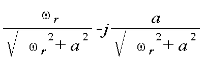
도 7을 참조하면, PMSM에서 플럭스 추정의 바람직한 방법에 있어서, 추정한 플럭스를 얻기 위해서 저역 통과 필터가 사용된다. 저역 통과 필터의 전달함수는 다음의 방정식 1로 나타내어진다:Referring to FIG. 7, in a preferred method of flux estimation in PMSM, a low-pass filter is used to obtain the estimated flux. The transfer function of the low-pass filter is represented by the following equation 1:

여기에서,From here,
s는 저역 통과 필터의 S-도메인 적분 연산을 나타내고, 그리고s represents the S-domain integral operation of the low-pass filter, and
a는 저역 통과 필터에 대한 오차수정변수이다.a is an error correction variable for the low-pass filter.
한 바람직한 실시 예에 있어서, 전달함수에 의해서 나타내어진 저역 통과 필터는 소프트웨어로 실행될 것이다. 이와는 달리, 저역 통과 필터는 하드웨어 성분들, 예를 들어 집적 회로, ASIC 또는 R-L-C 회로에서 실행될 것이다. 방정식 1에서 변수 a의 값을 증가시키면, 추정한 플럭스의 컨버전스는 짧은 시간 간격으로 일어날 수 있지만, 추정한 플럭스에서의 오차가 커질 것이다. 변수 a의 값을 감소시키면, 컨버전스의 변수 a의 값은 더 느려질 수 있지만, 추정한 플럭스에서의 오차는 작아질 것이다. 예를 들면, 회전자 속도가 94.25rad/s인 경우, 다른 "a"값은 다른 각도 오차들을 산출한다.In one preferred embodiment, the low-pass filter represented by the transfer function will be implemented in software. Alternatively, the low-pass filter may be implemented in hardware components, such as an integrated circuit, an ASIC, or an R-L-C circuit. By increasing the value of the variable a in
a = 2 sinΦ = 0.9997749 각도 오차 = 1.2167°a = 2 sin? = 0.9997749 Angle error = 1.2167 °
a = 4 sinΦ = 0.99910058 각도 오차 = 2.43025°a = 4 sin? = 0.99910058 Angular error = 2.43025?
a = 6 sinΦ = 0.99797971 각도 오차 = 3.64265°a = 6 sin? = 0.99797971 Angle error = 3.64265 °
a = 8 sinΦ = 0.99641682 각도 오차 = 4.851787°a = 8 sin? = 0.99641682 Angle error = 4.851787?
a = 10 sinΦ = 0.99441813 각도 오차 = 6.056610°a = 10 sin [phi] = 0.99441813 Angular error = 6.056610 [deg.]
개방 루프 추정방법(100)이 도 7에 도시되어 있다. α-축 전압(νa)이 가산 블록(102)의 입력(101)에 인가된다. 추정방법에 대한 입력은 α-β 좌표계에서 표현된 모터 위상 전류와 전압이다. 좌표계와 PMSM의 전압과 전류 벡터들은 위상 축 a, b 및 c가 되고, α-축과 β-축은 위상 a와 정렬된 고정 데카르트 좌표계를 나타내고; d-축과 q-축은 회전자 플럭스와 정렬된 회전 데카르트 좌표계를 나타낸다. α-축과 β-축에 대한 α-β 프레임 표현들은 클라아크 변환을 그들의 대응하는 3상 표시에 적용하여 얻어진다.The open
위상 a 고정자, 또는 전기자, 전류를 나타내는α-축 전류값 ia는 추정에 사용되는 전류를 예측하는 전류 예측모델(104)에 제공된다. 전류 예측모델(104)의 출력 ia는 고정자 권선에서 추정한 강하 전압을 발생시키도록 블록(106)에서 고정자 저항 rs를 곱하게 된다. 블록(106)의 출력은 가산 블록(102)에서 α-축 위상 전압(νa)로부터 차감되고, 블록(102)의 출력은 방정식 1의 전달함수로 표현되는 전달함수 블록(108)에 적용된다. 전달함수 블록(108)에 있어서, 필터 변수 a는 필요한 컨버전스 시간 내에 다른 속도범위로 최소 오차를 달성하기 위해서 도입된다. 블록(108)의 출력은 블록(108)에서 a에 의해서 도입된 오차를 줄이거나 제거하기 위해서 블록(110)에서 보완된다. 블록(108)의 출력은 가산 블록(102)에서 블록(114)의 출력과 결합된다. 블록(114)은 고정자 상호 인덕턴스(Lm)을 나타내는데, 이것은 블록(114)의 출력을 발생시키도록 입력 예측 전류(ia)이 곱해진 값이다. 블록(114)의 출력은, 블록(112)에서, 오차가 보상된 에어 갭 쇄교자속 또는 블록(110)의 출력으로부터 차감된다. 블록들(110,114)의 차이는 블록(112)의 출력이며, 이것은 α-축에서 추정한 회전자 쇄교자속을 나타낸다. 그러면, 회전자 위상 각도(θr)는 α-축과 β-축 모두로부터 추정한 회전자 쇄교자속을 사용하여 각도 계산 블록(116)에 의해서 추정된다. 추정한 회전자 위상 각도(θr)(120)가 블록(118)에 적용되고, 추정한 회전자 위상 각도(θr)(120)의 시간 도메인 파생이 회전자 주파수(ωr)로서 블록(117)의 출력에서 발생한다. Phase a stator, or armature, the a-axis current value i a representing the current is provided to the
PMSM(86)의 보다 정밀한 플럭스 추정은 소정의 인터벌로 변수 a의 값을 조정함으로써 달성될 것이다. 예를 들면, a의 값은 회전자 속도의 함수로서 변화할 것이며, 여기에서 a의 값은 처음에, 예를 들면 추정의 초기에 빠른 컨버전스를 얻기 위해서 PMSM(86)을 시작할 때 크다. 컨버전스 후에, 플럭스 추정에서 오차를 줄이기 위해 작은 값의 a가 적용된다. 또한, 한 바람직한 실시 예에 있어서, a의 값은 점진적으로 변환되거나, 개선된 장치 안정성을 제공하기 위해서 a의 높은 초기 값으로부터 a의 낮은 값으로 점점 저하된다. A more precise flux estimation of the
이 방법의 바람직한 실시 예는 다음과 같이 표현된다:A preferred embodiment of this method is expressed as follows:
점진적 저하 a:Gradual degradation a:
만일 (ωr > 1200 및 ωr < 1500)If ( r > 1200 and r < 1500)
a = 5-(ωr-1200)*0.01a = 5- (? r -1200) * 0.01
만일 (ωr > 1500)If ( r > 1500)
a = 2a = 2
("a" = 오차수정변수)("a" = error correction variable)
보상방법은 a로 인하여 추정오차를 줄이기 위해서 발표되었다. 추정한 쇄교자속은 2개 성분들을 포함하는데, 실제 성분 알파(α)와 가상 성분 베타(β)이다. 추정한 쇄교자속의 알파와 베타 성분들은 오차보정변수 a로 인하여 크기 오차를 보상하기 위해서 사용될 것이다. 크기 보상의 표현은 다음의 방정식으로 표현된다:The compensation method was introduced to reduce the estimation error due to a. The estimated flux linker contains two components: the actual component alpha (α) and the hypothetical component beta (β). The estimated alpha and beta components in the flux goniometer will be used to compensate for the magnitude error due to the error correction parameter a. The expression of the magnitude compensation is expressed by the following equation:

여기에서, From here,
a는 오차수정변수이고a is the error correction variable
![]()
![]()
제 2 단계는 위상 각도 수정을 위한 것이고, 이때 쇄교자속 복합변수는 2개의 성분, 즉 실제성분 알파와 가상성분 베타가 사용된다. 이러한 복합변수의 알파와 베타 성분들은 오차보정변수 a로 인하여 위상 오차를 보상하기 위해서 사용될 것이다. 위상 각도 보상을 위해서 사용된 복합변수의 표현은 다음으로 주어진다:The second step is for phase angle correction, in which the complex variable in the flux regulator is composed of two components: the actual component alpha and the hypothetical component beta. The alpha and beta components of this complex variable will be used to compensate for the phase error due to the error correction variable a. The expression of the complex variable used for phase angle compensation is given by:

만일 크기 보상과 위상 보상이 결합되면, 그 보상의 표현은 다음 방정식들로 주어진다:If the magnitude compensation and the phase compensation are combined, the representation of the compensation is given by the following equations:


여기에서, ![]()
![]()
![]()
![]()
![]()
![]()
![]()
![]()
샘플링 함수 대 기초 함수의 비율이 낮으므로, 샘플링 주파수를 증가시킴이 없이 비교적 긴 지연은 불가피하다. 샘플링 주파수를 증가시키면 제어장치의 비용이 증가하게 된다. 전류 예측방법은 샘플링 주파수를 증가시킬 필요없이 샘플링 지연의 영향을 제거하도록 전류를 예측하기 위해서 채용될 수 있다. 고속 및 초고속 응용에 있어서, 사이클당 샘플링 수는 크게 줄어들게 된다. 추정 오차를 줄이기 위해서, Nth 샘플링 인터벌에서 전류는 다음 (N+1)th 샘플링 인터벌에서 전류를 예측하기 위해 사용될 것이다. 예측된 전류는 쇄교자속 추정에서의 오차를 줄이기 위해서 사용될 것이다. 전류 예측은 PMSM 기계장치 모델을 기초로 한다.Since the ratio of the sampling function to the fundamental function is low, a relatively long delay is inevitable without increasing the sampling frequency. Increasing the sampling frequency increases the cost of the control unit. The current predicting method can be employed to predict the current to eliminate the effect of the sampling delay without the need to increase the sampling frequency. In high speed and high speed applications, the number of samples per cycle is greatly reduced. To reduce the estimation error, the current in the N th sampling interval will be used to predict the current in the next (N + 1) th sampling interval. The predicted current will be used to reduce the error in the flux gauge estimation. Current prediction is based on the PMSM machine model.
이러한 방법의 바람직한 실시 예가 설명된다.A preferred embodiment of such a method is described.
예측방법은 q-d 참조를 기초한다:The prediction method is based on the q-d reference:
예측된 q-축 전류는 다음과 같이 주어진다:The predicted q-axis current is given by:

예측된 d-축 전류는 다음과 같이 주어진다:The predicted d-axis current is given by:

여기에서, ![]()
![]()
![]()
![]()
![]()
![]()
![]()
![]()
![]()
![]()
![]()
![]()
![]()
![]()
![]()
![]()
![]()
![]()
위에서는 무센서 PMSM을 제어하기 위한 제어장치 및 방법을 설명하였지만, 모터의 각 위치와 속도를 추정하기 위한 제어장치 및 방법은 다른 형식의 무센서, 동기 모터, 예를 들면 유도타입 전동기들에 적용될 수 있으며, 그러한 동기 모터들은 여기에서 설명하고 청구하는 제어장치의 영역 내에서 고려된다.Although the control apparatus and method for controlling the sensorless PMSM have been described above, the control apparatus and method for estimating the respective positions and speeds of the motors are applicable to other types of sensors, synchronous motors, for example, induction type motors And such synchronous motors are contemplated within the scope of the control device described and claimed herein.
본 출원은 다음의 설명이나 도면에 도시된 상세한 내용들이나 방법론으로 제한되지 않음을 이해하여야 한다. 여기에서 채용된 어법과 전문용어는 단지 설명을 위한 목적으로서 채용된 것으로 본 발명을 제한하기 위한 것이 아님을 이해하여야 한다.It is to be understood that the present application is not limited to the details and methodology shown in the following description or drawings. It is to be understood that the phraseology and terminology employed herein is for the purpose of description and is not intended to be limiting of the invention.
바람직한 실시 예들이 도면에 도시되고 여기에서 설명되었지만, 이러한 실시 예들은 단지 예로서 주어진 것임을 이해하여야 한다. 따라서, 본 발명은 특별한 실시 예로서 제한되지 않으며, 다양한 변형으로 확장이 가능하다. 공정이나 방법 단계들의 순서나 절차는 대안적인 실시 예들에 따라서 변화하거나 그 순서를 다시 배열할 수 있을 것이다.While preferred embodiments have been shown and described herein, it should be understood that these embodiments are given by way of example only. Therefore, the present invention is not limited to a specific embodiment, and can be extended to various modifications. The sequence or procedure of the process or method steps may be varied or rearranged according to alternative embodiments.
본 출원은 방법, 장치 및 그것의 작동을 달성하기 위한 기계판독 가능매체상의 프로그램 제품을 고려한 것이다. 본 출원의 실시 예들은 현존 컴퓨터 프로세서들을 사용하여 실행되거나, 또는 이것 또는 다른 목적을 위해서 통합된 적절한 장치를 위한 특별한 목적의 컴퓨터 프로세서, 또는 하드웨어 시스템에 의해서 실행될 것이다. The present application contemplates a method, apparatus and program product on a machine-readable medium for effecting its operation. Embodiments of the present application may be implemented by means of special purpose computer processors, or hardware systems, for execution by means of existing computer processors or for appropriate devices incorporated for this or other purposes.
다양한 바람직한 실시 예들에서 보여진 바와 같이 PMSM 제어를 위한 플럭스 추정방법의 구성 및 배열은 단지 설명만을 위한 것임을 주목해야 한다. 비록 본 명세서에서는 적은 수의 실시 예들이 상세하게 설명되었지만, 본 명세서를 읽는 사람들은 본 출원에서 인용한 주제의 새로운 기술이나 장점들을 벗어남이 없이 많은 변형들(예를 들면, 크기, 치수, 구조, 형상, 다양한 요소들의 비율, 매개변수들의 값, 장착 배열, 재료의 사용, 색채, 배향 등에서의 변화)이 가능함을 쉽게 이해할 수 있을 것이다. 예를 들면, 일체로 형성된 것으로 보여진 요소들은 다중의 부분이나 요소들로 구성될 수도 있고, 요소들의 위치는 뒤바뀌거나 다르게 변할 수 있으며, 불균일한 요소들의 특성이나 수 그리고 위치는 바뀌거나 변할 수 있다. 따라서, 모든 그러한 변형들은 본 출원의 영역 내에 포함되도록 의도된다. 소정 공정이나 방법의 순서나 절차는 대안적인 실시 예들에 따라서 변하거나 순서를 다시 정할 수 있다. 본 출원의 영역을 벗어남이 없이 바람직한 실시 예들의 설계, 작동조건 및 배열에 있어서 다른 대체, 변형, 변화 및 생략이 이루어질 수 있다. It should be noted that the construction and arrangement of the flux estimation method for PMSM control as shown in various preferred embodiments is for illustrative purposes only. Although a few embodiments have been described in detail herein, those skilled in the art will readily appreciate that many modifications (e. G., Size, dimensions, Shape, ratio of various elements, value of parameters, mounting arrangement, use of material, change in color, orientation, etc.). For example, elements shown as being integrally formed may consist of multiple portions or elements, the positions of the elements may be reversed or otherwise changed, and the nature, number and position of the non-uniform elements may be varied or varied . Accordingly, all such modifications are intended to be included within the scope of the present application. The order or procedure of a given process or method may be varied or reordered according to alternative embodiments. Other permutations, modifications, changes and omissions in the design, operating conditions and arrangements of the preferred embodiments can be made without departing from the scope of the present application.
상기한 바와 같이, 본 출원의 영역 내에 있는 실시 예들은 기계에서 실행가능한 명령어들 또는 거기에 저장된 데이터 구조를 보유하거나 갖는 기계판독 가능매체을 구비한 프로그램 제품을 포함한다. 그러한 기계판독 가능매체는 일반적 목적이나 특별한 목적의 컴퓨터나 프로세서를 갖춘 다른 기계장치에 의해서 접근 가능한 유용한 매체가 될 수 있다. 예를 들면, 그러한 기계판독 가능매체는 RAM, ROM, EPROM, EEPROM, CD-ROM 또는 다른 광학 디스크 스토리지, 자기디스크 스토리지, 또는 기계에서 실행가능한 명령어들이나 데이터 구조의 형태로 원하는 프로그램 코드를 보유하거나 저장하도록 사용될 수 있고 일반적 목적이나 특별한 목적의 컴퓨터나 프로세서를 갖춘 다른 기계장치에 의해서 접근 가능한 다른 자기 저장장치들이나 소정의 다른 매체를 포함할 수 있다. 정보가 네트워크나 다른 통신 연결(하드워어, 무선 또는 하드웨어나 무선의 조합)을 통해서 기계장치로 전달되거나 제공되는 경우에, 기계장치는 기계판독 가능매체로서 그 통신 연결을 적절하게 본다. 그러므로, 그러한 연결은 기계판독 가능매체에 적절히 주어진다. 상기한 조합은 기계판독 가능매체의 영역 내에서 포함된다. 기계적으로 실행가능한 명령어들은 예를 들면 일반적 목적의 컴퓨터, 특별한 목적의 컴퓨터 또는 특별한 목적의 처리기계장치로 하여금 어떤 기능이나 기능들의 그룹을 수행하도록 하기 위한 명령어들과 데이터를 포함한다. As noted above, embodiments within the scope of the present application include program products with machine-readable media having or having machine-executable instructions or data structures stored thereon. Such machine-readable media can be any useful medium accessible by a general purpose or special purpose computer or other machine having a processor. For example, such a machine-readable medium may include or store a desired program code in the form of a RAM, ROM, EPROM, EEPROM, CD-ROM or other optical disk storage, magnetic disk storage, And may include other magnetic storage devices or any other medium that can be used for general purpose or special purpose computer or other mechanical means with a processor. In the case where information is communicated or provided to a machine via a network or other communication connection (hardwar, wireless or a combination of hardware or wireless), the machine properly sees its communication connection as a machine-readable medium. Therefore, such connection is appropriately given to a machine-readable medium. The combination is included within the scope of the machine-readable medium. The mechanically executable instructions include, for example, instructions and data for causing a general purpose computer, special purpose computer, or special purpose processing device to perform a certain function or group of functions.
비록 첨부도면들은 본 발명의 단계들의 특별한 순서를 나타내었지만, 이러한 단계들의 순서는 도시한 것과 다를 수 있음을 이해할 수 있을 것이다. 또한, 둘 또는 그 이상의 단계들은 동시에 또는 시차를 두고 수행될 수 있을 것이다. 그러한 변화는 소프트웨어와 하드웨어 시스템의 선택과 디자이너의 선택에 의존하게 된다. 모든 그러한 변화들은 본 출원의 영역 내에 있음을 이해할 수 있을 것이다. 마찬가지로, 소프트웨어 실행은 다양한 연결단계들, 처리단계들 및 결정단계들을 달성하기 위한 룰 기초 로직과 다른 로직에 따른 표준 프로그래밍 기술들을 사용하여 달성될 수 있다.Although the appended drawings illustrate a particular sequence of steps of the present invention, it will be understood that the order of these steps may be different from that shown. Further, two or more steps may be performed simultaneously or at different time intervals. Such changes will depend on the choice of software and hardware system and the designer's choice. It is to be understood that all such variations are within the scope of the present application. Likewise, software execution can be accomplished using standard programming techniques along with rule-based logic and other logic to achieve various connection steps, processing steps, and decision steps.
Claims (21)
상기 동기모터의 고정자 권선의 전압을 전달함수에 적용하는 단계로써, 상기 전달함수는 에스(S)-도메인 적분 연산과 오차수정변수를 포함하여, 아래 식과 같이 표현되고,
1/(s + a)
여기서, s는 에스(S)-도메인 적분 연산을 나타내고,
a = 오차수정변수이며,
상기 전달함수로 도입된 상기 오차수정변수를 보상하기 위해서 상기 전달함수의 출력을 처리하는 단계;
추정된 회전자 쇄교자속을 발생시키는 단계;
추정된 회전자 쇄교 자속을 각도 계산 블록에 입력하여 상기 회전자 위치의 각도를 계산하되, 상기 회전자 위치의 각도는 알파(α)-축과 베타(β)-축으로부터 상기 추정된 쇄교자속을 이용하여 상기 각도 계산 블록에 의해 추정되는 단계; 그리고
상기 동기모터의 위치나 속도를 제어하기 위해서 계산된 회전자 위치를 컨트롤러에 입력하는 단계;
알파(α)-축 전류와 베타(β)-축 전류를 결정하고, 결정된 상기 알파(α)-축 전류와 상기 베타(β)-축 전류를 전류 예측 모델에 적용함으로써, 다음 시간 간격에서 고정자 전류값을 예측하는 단계를 포함하는 방법. A method for controlling a synchronous motor by determining a rotor position of a synchronous motor by estimating a flux reciprocator,
Applying a voltage of a stator winding of the synchronous motor to a transfer function, the transfer function including an S (S) - domain integration operation and an error correction variable,
1 / (s + a)
Where s denotes an S (S) -domain integration operation,
a = error correction variable,
Processing an output of the transfer function to compensate for the error correction variable introduced into the transfer function;
Generating an estimated flux linkage;
Calculating an angle of the rotor position by inputting the estimated rotor flux link into the angle calculation block, wherein the angle of the rotor position is determined from the alpha (-) - axis and the beta (- Estimating by the angle calculation block using the angle calculation block; And
Inputting the calculated rotor position to the controller to control the position or speed of the synchronous motor;
By determining the alpha -axis current and beta beta -axis current and applying the determined alpha -axis current and beta beta -axis current to the current prediction model, And estimating a current value.

여기에서, a는 오차수정변수이고
Where a is the error correction variable
에 의해서 표현되는 방법.12. The method of claim 11, wherein the complexity complex variable comprises an actual component and a hypothetical component, wherein the complexity complex variable is employed to compensate for phase error due to the error correction variable, The following equation:
≪ / RTI >


여기에서,
ωr은 회전자 속도인 방법.13. The method of claim 12, further comprising combining magnitude compensation and phase compensation, wherein the combination of magnitude compensation and phase compensation comprises:
From here,
r is the rotor speed.
첫번째 샘플링 인터벌하에서 고정자 전류값과 고정자 권선 전압을 결정하는 단계;
상기 첫번째 샘플링 인터벌하에서 결정된 고정자 전류값과 고정자 권선 전압을 기초하여 다음번 샘플링 인터벌하에서 상기 고정자 전류값을 예측하는 단계;
추정한 쇄교자속에서의 오차를 줄이기 위해서 상기 다음번 샘플링 인터벌하에서 예측한 고정자 전류값을 적용하는 단계를 더 포함하는 방법.The method according to claim 1,
first Determining a stator current value and a stator winding voltage under a sampling interval;
Predicting the stator current value under the next sampling interval based on the stator current value and the stator winding voltage determined under the first sampling interval;
And applying the predicted stator current value under the next sampling interval to reduce the error in the estimated flux.
상기 동기모터의 회전자의 속도의 함수로서 오차수정변수의 값을 변화시키는 단계;
소정의 초기 모터 기동 인터벌에 걸쳐서 빠른 컨버전스를 얻도록 구성된 오차수정변수의 제 1 값을 적용하는 단계; 그리고
상기 소정의 초기 모터 기동 인터벌 후에 상기 오차수정변수의 제 2 값을 적용하는 단계 - 상기 제 2 값은 플럭스 추정에서 오차를 줄이도록 구성됨 -;를 더 포함하는 방법.The method according to claim 1,
Changing the value of the error correction variable as a function of the speed of the rotor of the synchronous motor;
Applying a first value of an error correction variable configured to obtain a fast convergence over a predetermined initial motor start interval; And
Applying a second value of the error correction variable after the predetermined initial motor start interval, wherein the second value is configured to reduce the error in the flux estimation.
(ⅱ) 상기 압축기에 동력을 제공하도록 상기 압축기에 연결된 동기모터;
(ⅲ) 상기 동기모터에 연결되고, 고정된 입력 AC 전압과 고정된 입력 주파수하에서 입력 AC 전력을 수용하고 가변 전압과 가변 주파수하에서 출력 전력을 동기모터로 제공하도록 배열된 가변속 드라이브 -
상기 가변속 드라이브는,
(a) 입력 AC 전압을 제공하는 AC 전력원에 연결 가능한 컨버터 - 상기 컨버터는 입력 AC 전압을 DC 전압으로 변환하도록 배열됨 -;
(b) 상기 컨버터에 연결된 DC 링크 - 상기 DC 링크는 컨버터 스테이지로부터 나오는 DC 전압을 필터링하고 저장하도록 구성됨 -;
(c) 상기 DC 링크에 연결된 인버터;를 포함함 -; 그리고
(ⅳ) 추정한 쇄교자속으로부터 회전자 각도에 기초하여 상기 동기모터의 회전자 속도를 제어하도록 구성되고, 결정된 알파(α)-축 전류와 결정된 베타(β)-축 전류에 기초하여 다음 시간 간격에서 고정자 전류값을 예측하되, 결정된 상기 알파(α)-축 전류와 상기 베타(β)-축 전류를 전류 예측 모델에 적용하도록 구성된 컨트롤러;를 포함하며,
에스(S)-도메인 적분 연산과 오차수정변수를 포함하는 전달함수에 상기 동기모터의 고정자 권선의 전압을 적용하고;
상기 전달함수로 도입된 상기 오차수정변수를 보상하기 위해서 상기 전달함수의 출력을 처리하고;
추정된 회전자 쇄교자속을 발생시키고;
추정된 회전자 쇄교 자속을 기초로 상기 회전자 위치의 각도를 계산하며;
상기 컨트롤러로 계산된 회전자 위치를 입력하도록 구성되며;
상기 전달함수는
1/(s + a)
여기서, s는 에스(S)-도메인 적분 연산을 나타내고,
a = 오차수정변수
와 같이 표현되는 냉각장치.
(i) a compressor connected in a closed cooling loop, a condenser and an evaporator;
(Ii) a synchronous motor coupled to the compressor to provide power to the compressor;
(Iii) a variable speed drive coupled to the synchronous motor and arranged to receive the input AC voltage at a fixed input frequency and a fixed input frequency and to provide the output power under a variable voltage and variable frequency to a synchronous motor,
The variable-
(a) a converter connectable to an AC power source providing an input AC voltage, the converter being arranged to convert an input AC voltage to a DC voltage;
(b) a DC link coupled to the converter, the DC link configured to filter and store a DC voltage from the converter stage;
(c) an inverter coupled to the DC link; And
(Iv) a controller configured to control the rotor speed of the synchronous motor based on the rotor angle from the estimated flux regenerator, and to determine a next time based on the determined alpha (alpha) -axis current and the determined beta And a controller configured to predict the stator current value at the interval, and to apply the determined alpha -axis current and the beta beta -axis current to the current prediction model,
Applying a voltage of a stator winding of the synchronous motor to a transfer function including an S (S) -domain integration operation and an error correction variable;
Process the output of the transfer function to compensate for the error correction variable introduced into the transfer function;
To generate an estimated rotor flux;
Calculate an angle of the rotor position based on the estimated rotor flux linkage;
And to input a rotor position calculated by the controller;
The transfer function
1 / (s + a)
Where s denotes an S (S) -domain integration operation,
a = error correction variable
/ RTI >

여기에서, a는 오차수정변수이고
Where a is the error correction variable

에 의해서 표현되는 냉각장치.20. The method of claim 19, wherein the complexity complex variable comprises an actual component and a virtual component, wherein the complexity complex variable is employed to compensate for phase error due to the error correction variable, The following equation:
Lt; / RTI >


여기에서,
ωr은 회전자 속도인 냉각장치.17. The method of claim 16, wherein magnitude compensation and phase compensation are combined and the combination of magnitude compensation and phase compensation is performed using the following equation:
From here,
and? r is the rotor speed.
Applications Claiming Priority (3)
| Application Number | Priority Date | Filing Date | Title |
|---|---|---|---|
| US31142010P | 2010-03-08 | 2010-03-08 | |
| US61/311,420 | 2010-03-08 | ||
| PCT/US2011/026045 WO2011112363A2 (en) | 2010-03-08 | 2011-02-24 | Method and system for controlling a permanent magnet synchronous motor |
Related Child Applications (1)
| Application Number | Title | Priority Date | Filing Date |
|---|---|---|---|
| KR1020147030461A Division KR101554886B1 (en) | 2010-03-08 | 2011-02-24 | Method and system for controlling a permagnent magnet synchronous motor |
Publications (2)
| Publication Number | Publication Date |
|---|---|
| KR20120136385A KR20120136385A (en) | 2012-12-18 |
| KR101534518B1 true KR101534518B1 (en) | 2015-07-07 |
Family
ID=44564059
Family Applications (2)
| Application Number | Title | Priority Date | Filing Date |
|---|---|---|---|
| KR1020147030461A KR101554886B1 (en) | 2010-03-08 | 2011-02-24 | Method and system for controlling a permagnent magnet synchronous motor |
| KR1020127026194A KR101534518B1 (en) | 2010-03-08 | 2011-02-24 | Method and system for controlling a permagnent magnet synchronous motor |
Family Applications Before (1)
| Application Number | Title | Priority Date | Filing Date |
|---|---|---|---|
| KR1020147030461A KR101554886B1 (en) | 2010-03-08 | 2011-02-24 | Method and system for controlling a permagnent magnet synchronous motor |
Country Status (7)
| Country | Link |
|---|---|
| US (4) | US9490733B2 (en) |
| EP (2) | EP2545642B1 (en) |
| JP (1) | JP2013523065A (en) |
| KR (2) | KR101554886B1 (en) |
| CN (2) | CN105591583B (en) |
| TW (1) | TWI505630B (en) |
| WO (1) | WO2011112363A2 (en) |
Families Citing this family (17)
| Publication number | Priority date | Publication date | Assignee | Title |
|---|---|---|---|---|
| KR101554886B1 (en) * | 2010-03-08 | 2015-09-24 | 존슨 컨트롤스 테크놀러지 컴퍼니 | Method and system for controlling a permagnent magnet synchronous motor |
| FR2984637B1 (en) * | 2011-12-20 | 2013-11-29 | IFP Energies Nouvelles | METHOD FOR DETERMINING THE POSITION AND SPEED OF A ROTOR OF A SYNCHRONOUS ELECTRIC MACHINE |
| JP6511224B2 (en) * | 2014-04-23 | 2019-05-15 | 日立オートモティブシステムズ株式会社 | Power supply |
| KR101840509B1 (en) | 2014-04-29 | 2018-03-20 | 엘에스산전 주식회사 | Rotation angle estimation module for sensorless vector control of PMSM |
| JP6375757B2 (en) * | 2014-07-29 | 2018-08-22 | 株式会社安川電機 | Electric motor control device, electric motor magnetic flux estimation device, and electric motor magnetic flux estimation method |
| CN104791953B (en) * | 2015-04-16 | 2017-10-13 | 广东美的制冷设备有限公司 | The control method of compressor electric motor, control device in air conditioner and air conditioner |
| JP6436114B2 (en) | 2016-02-19 | 2018-12-12 | 株式会社豊田自動織機 | Permanent magnet rotating electric machine |
| CN106160615A (en) * | 2016-08-03 | 2016-11-23 | 珠海格力节能环保制冷技术研究中心有限公司 | Electric machine control system, compressor and motor heating starting method |
| US10960922B2 (en) * | 2017-01-31 | 2021-03-30 | Steering Solutions Ip Holding Corporation | Fault tolerant field oriented control for electric power steering |
| US10515098B2 (en) | 2017-02-10 | 2019-12-24 | Johnson Controls Technology Company | Building management smart entity creation and maintenance using time series data |
| US10417245B2 (en) * | 2017-02-10 | 2019-09-17 | Johnson Controls Technology Company | Building management system with eventseries processing |
| CN110326194B (en) * | 2017-02-27 | 2021-07-06 | 东芝三菱电机产业系统株式会社 | Control device |
| JP6629814B2 (en) * | 2017-10-19 | 2020-01-15 | ファナック株式会社 | Motor control device |
| CN108471198B (en) * | 2018-04-26 | 2023-07-28 | 北京建筑大学 | Control method, device and system for switched reluctance motor and controller |
| US11305784B2 (en) * | 2019-12-30 | 2022-04-19 | Karma Automotive Llc | Method for online direct estimation and compensation of flux and torque errors in electric drives |
| US11196371B2 (en) | 2020-01-10 | 2021-12-07 | DRiV Automotive Inc. | Sensorless position detection for electric motor |
| JP2022175990A (en) * | 2021-05-14 | 2022-11-25 | 株式会社日立産機システム | Power conversion device |
Citations (2)
| Publication number | Priority date | Publication date | Assignee | Title |
|---|---|---|---|---|
| US20040056629A1 (en) * | 2000-11-09 | 2004-03-25 | Toshiyuki Maeda | Synchronous motor control method and device |
| US20070194742A1 (en) * | 2006-02-20 | 2007-08-23 | Hamilton Sundstrand Corporation | Angular position and velocity estimation for synchronous machines based on extended rotor flux |
Family Cites Families (19)
| Publication number | Priority date | Publication date | Assignee | Title |
|---|---|---|---|---|
| US5334923A (en) * | 1990-10-01 | 1994-08-02 | Wisconsin Alumni Research Foundation | Motor torque control method and apparatus |
| JPH05204461A (en) * | 1991-09-26 | 1993-08-13 | Toyoda Mach Works Ltd | Digital servo control device |
| US6731083B2 (en) * | 1998-06-02 | 2004-05-04 | Switched Reluctance Drives, Ltd. | Flux feedback control system |
| US6552509B2 (en) | 2000-05-10 | 2003-04-22 | Gti Electroproject B.V. | Method and a device for sensorless estimating the relative angular position between the stator and rotor of a three-phase synchronous motor |
| CN101222204A (en) * | 2001-09-29 | 2008-07-16 | 大金工业株式会社 | Phase current detection method and apparatus |
| EP3203628A1 (en) * | 2002-02-25 | 2017-08-09 | Daikin Industries, Ltd. | Motor controlling method and apparatus thereof |
| TW594685B (en) * | 2002-04-26 | 2004-06-21 | Elan Microelectronics Corp | Automatic regulation encoding/decoding device of code length and method thereof |
| US7006338B2 (en) * | 2002-09-23 | 2006-02-28 | Siemens Energy & Automation, Inc. | System and method for individual phase motor over voltage protection |
| FI114420B (en) * | 2002-10-18 | 2004-10-15 | Abb Oy | Method for Full-Order Goat Detectors for Sensorless Short Circuit Motors |
| JP2004215318A (en) * | 2002-12-26 | 2004-07-29 | Aisin Aw Co Ltd | Apparatus and method for motor operated drive controlling and its program |
| JP5170505B2 (en) * | 2007-02-07 | 2013-03-27 | 株式会社ジェイテクト | Motor control device |
| WO2008137276A1 (en) * | 2007-05-08 | 2008-11-13 | Johnson Controls Technology Company | Variable speed drive |
| CN101369797A (en) * | 2007-08-13 | 2009-02-18 | 海信(北京)电器有限公司 | Vector control circuit and control method of electric motor |
| US8567207B2 (en) * | 2007-10-31 | 2013-10-29 | Johnson Controls & Technology Company | Compressor control system using a variable geometry diffuser |
| CN101286725A (en) * | 2008-04-17 | 2008-10-15 | 戴政 | Deriving method of motor rotative velocity and location of rotor in synchronous electric machine vector control system |
| JP2009268267A (en) | 2008-04-25 | 2009-11-12 | Sanyo Electric Co Ltd | Motor controller and generator controller |
| US8336323B2 (en) | 2008-10-03 | 2012-12-25 | Johnson Controls Technology Company | Variable speed drive with pulse-width modulated speed control |
| JP2011125107A (en) * | 2009-12-09 | 2011-06-23 | Sanyo Electric Co Ltd | Motor control device, motor drive system, and inverter control device |
| KR101554886B1 (en) * | 2010-03-08 | 2015-09-24 | 존슨 컨트롤스 테크놀러지 컴퍼니 | Method and system for controlling a permagnent magnet synchronous motor |
-
2011
- 2011-02-24 KR KR1020147030461A patent/KR101554886B1/en active IP Right Grant
- 2011-02-24 KR KR1020127026194A patent/KR101534518B1/en active IP Right Grant
- 2011-02-24 EP EP11708614.0A patent/EP2545642B1/en active Active
- 2011-02-24 CN CN201610086180.9A patent/CN105591583B/en active Active
- 2011-02-24 CN CN201180012731.2A patent/CN102792580B/en active Active
- 2011-02-24 EP EP16194425.1A patent/EP3154183B1/en active Active
- 2011-02-24 JP JP2012557075A patent/JP2013523065A/en active Pending
- 2011-02-24 US US13/579,464 patent/US9490733B2/en active Active
- 2011-02-24 WO PCT/US2011/026045 patent/WO2011112363A2/en active Application Filing
- 2011-03-04 TW TW100107369A patent/TWI505630B/en not_active IP Right Cessation
-
2016
- 2016-03-31 US US15/088,092 patent/US9941825B2/en active Active
- 2016-03-31 US US15/088,095 patent/US9979332B2/en active Active
- 2016-03-31 US US15/088,096 patent/US9923497B2/en active Active
Patent Citations (2)
| Publication number | Priority date | Publication date | Assignee | Title |
|---|---|---|---|---|
| US20040056629A1 (en) * | 2000-11-09 | 2004-03-25 | Toshiyuki Maeda | Synchronous motor control method and device |
| US20070194742A1 (en) * | 2006-02-20 | 2007-08-23 | Hamilton Sundstrand Corporation | Angular position and velocity estimation for synchronous machines based on extended rotor flux |
Also Published As
| Publication number | Publication date |
|---|---|
| CN102792580B (en) | 2016-01-13 |
| KR101554886B1 (en) | 2015-09-24 |
| JP2013523065A (en) | 2013-06-13 |
| WO2011112363A3 (en) | 2012-07-26 |
| US20130141024A1 (en) | 2013-06-06 |
| KR20120136385A (en) | 2012-12-18 |
| KR20140137460A (en) | 2014-12-02 |
| CN105591583B (en) | 2019-06-28 |
| EP2545642B1 (en) | 2016-10-19 |
| US9490733B2 (en) | 2016-11-08 |
| EP3154183A2 (en) | 2017-04-12 |
| TW201206049A (en) | 2012-02-01 |
| EP3154183B1 (en) | 2020-09-09 |
| CN102792580A (en) | 2012-11-21 |
| US9979332B2 (en) | 2018-05-22 |
| CN105591583A (en) | 2016-05-18 |
| US20160218651A1 (en) | 2016-07-28 |
| EP2545642A2 (en) | 2013-01-16 |
| US9923497B2 (en) | 2018-03-20 |
| EP3154183A3 (en) | 2017-11-15 |
| TWI505630B (en) | 2015-10-21 |
| US20160218653A1 (en) | 2016-07-28 |
| US20160218654A1 (en) | 2016-07-28 |
| US9941825B2 (en) | 2018-04-10 |
| WO2011112363A2 (en) | 2011-09-15 |
Similar Documents
| Publication | Publication Date | Title |
|---|---|---|
| KR101534518B1 (en) | Method and system for controlling a permagnent magnet synchronous motor | |
| JP2012005199A (en) | Motor controller, compressor and heat pump device | |
| CN109478865B (en) | Motor drive device, refrigerator, and air conditioner | |
| CN106687751A (en) | Indoor unit and air conditioning apparatus | |
| CN101946136B (en) | Refrigeration equipment | |
| JP4744505B2 (en) | Motor drive control device, motor drive control method and coordinate conversion method, ventilation fan, liquid pump, blower, refrigerant compressor, air conditioner, and refrigerator | |
| EP2073373A2 (en) | Method for controlling motor of air conditioner | |
| JP2008295204A (en) | Apparatus and method for motor control | |
| JP2005265220A (en) | Gas heat pump type air conditioner | |
| JP2009017613A (en) | Controller, drive system, and heat transfer system | |
| KR102010388B1 (en) | Power converting apparatus and air conditioner including the same | |
| JP7201952B2 (en) | Motor controllers, motors, compressors, refrigerators and vehicles | |
| JP7237746B2 (en) | Open winding motor drive device and refrigeration cycle device | |
| TWI662782B (en) | Motor driving device, refrigeration cycle device including the same, and motor driving method | |
| KR102080519B1 (en) | Motor driving device and air conditioner including the same | |
| CN115603623A (en) | Control method and device of variable frequency motor without electrolytic capacitor and household appliance | |
| JP2013055745A (en) | Motor drive device |
Legal Events
| Date | Code | Title | Description |
|---|---|---|---|
| A201 | Request for examination | ||
| E902 | Notification of reason for refusal | ||
| AMND | Amendment | ||
| A107 | Divisional application of patent | ||
| AMND | Amendment | ||
| E90F | Notification of reason for final refusal | ||
| AMND | Amendment | ||
| X701 | Decision to grant (after re-examination) | ||
| GRNT | Written decision to grant | ||
| FPAY | Annual fee payment |
Payment date: 20180626 Year of fee payment: 4 |
|
| FPAY | Annual fee payment |
Payment date: 20190625 Year of fee payment: 5 |