EP3154151A1 - Distribution de puissance, réseau de données et architectures de commande intégrés dans un véhicule - Google Patents
Distribution de puissance, réseau de données et architectures de commande intégrés dans un véhicule Download PDFInfo
- Publication number
- EP3154151A1 EP3154151A1 EP16192280.2A EP16192280A EP3154151A1 EP 3154151 A1 EP3154151 A1 EP 3154151A1 EP 16192280 A EP16192280 A EP 16192280A EP 3154151 A1 EP3154151 A1 EP 3154151A1
- Authority
- EP
- European Patent Office
- Prior art keywords
- data
- control
- node
- power
- electrical power
- Prior art date
- Legal status (The legal status is an assumption and is not a legal conclusion. Google has not performed a legal analysis and makes no representation as to the accuracy of the status listed.)
- Withdrawn
Links
Images


Classifications
-
- H—ELECTRICITY
- H02—GENERATION; CONVERSION OR DISTRIBUTION OF ELECTRIC POWER
- H02J—CIRCUIT ARRANGEMENTS OR SYSTEMS FOR SUPPLYING OR DISTRIBUTING ELECTRIC POWER; SYSTEMS FOR STORING ELECTRIC ENERGY
- H02J3/00—Circuit arrangements for ac mains or ac distribution networks
-
- G—PHYSICS
- G05—CONTROLLING; REGULATING
- G05B—CONTROL OR REGULATING SYSTEMS IN GENERAL; FUNCTIONAL ELEMENTS OF SUCH SYSTEMS; MONITORING OR TESTING ARRANGEMENTS FOR SUCH SYSTEMS OR ELEMENTS
- G05B19/00—Programme-control systems
- G05B19/02—Programme-control systems electric
- G05B19/04—Programme control other than numerical control, i.e. in sequence controllers or logic controllers
- G05B19/042—Programme control other than numerical control, i.e. in sequence controllers or logic controllers using digital processors
- G05B19/0423—Input/output
-
- B—PERFORMING OPERATIONS; TRANSPORTING
- B60—VEHICLES IN GENERAL
- B60R—VEHICLES, VEHICLE FITTINGS, OR VEHICLE PARTS, NOT OTHERWISE PROVIDED FOR
- B60R16/00—Electric or fluid circuits specially adapted for vehicles and not otherwise provided for; Arrangement of elements of electric or fluid circuits specially adapted for vehicles and not otherwise provided for
- B60R16/02—Electric or fluid circuits specially adapted for vehicles and not otherwise provided for; Arrangement of elements of electric or fluid circuits specially adapted for vehicles and not otherwise provided for electric constitutive elements
- B60R16/023—Electric or fluid circuits specially adapted for vehicles and not otherwise provided for; Arrangement of elements of electric or fluid circuits specially adapted for vehicles and not otherwise provided for electric constitutive elements for transmission of signals between vehicle parts or subsystems
-
- B—PERFORMING OPERATIONS; TRANSPORTING
- B60—VEHICLES IN GENERAL
- B60R—VEHICLES, VEHICLE FITTINGS, OR VEHICLE PARTS, NOT OTHERWISE PROVIDED FOR
- B60R16/00—Electric or fluid circuits specially adapted for vehicles and not otherwise provided for; Arrangement of elements of electric or fluid circuits specially adapted for vehicles and not otherwise provided for
- B60R16/02—Electric or fluid circuits specially adapted for vehicles and not otherwise provided for; Arrangement of elements of electric or fluid circuits specially adapted for vehicles and not otherwise provided for electric constitutive elements
- B60R16/03—Electric or fluid circuits specially adapted for vehicles and not otherwise provided for; Arrangement of elements of electric or fluid circuits specially adapted for vehicles and not otherwise provided for electric constitutive elements for supply of electrical power to vehicle subsystems or for
-
- H—ELECTRICITY
- H02—GENERATION; CONVERSION OR DISTRIBUTION OF ELECTRIC POWER
- H02J—CIRCUIT ARRANGEMENTS OR SYSTEMS FOR SUPPLYING OR DISTRIBUTING ELECTRIC POWER; SYSTEMS FOR STORING ELECTRIC ENERGY
- H02J13/00—Circuit arrangements for providing remote indication of network conditions, e.g. an instantaneous record of the open or closed condition of each circuitbreaker in the network; Circuit arrangements for providing remote control of switching means in a power distribution network, e.g. switching in and out of current consumers by using a pulse code signal carried by the network
-
- H—ELECTRICITY
- H02—GENERATION; CONVERSION OR DISTRIBUTION OF ELECTRIC POWER
- H02J—CIRCUIT ARRANGEMENTS OR SYSTEMS FOR SUPPLYING OR DISTRIBUTING ELECTRIC POWER; SYSTEMS FOR STORING ELECTRIC ENERGY
- H02J4/00—Circuit arrangements for mains or distribution networks not specified as ac or dc
-
- B—PERFORMING OPERATIONS; TRANSPORTING
- B64—AIRCRAFT; AVIATION; COSMONAUTICS
- B64D—EQUIPMENT FOR FITTING IN OR TO AIRCRAFT; FLIGHT SUITS; PARACHUTES; ARRANGEMENTS OR MOUNTING OF POWER PLANTS OR PROPULSION TRANSMISSIONS IN AIRCRAFT
- B64D2221/00—Electric power distribution systems onboard aircraft
-
- G—PHYSICS
- G05—CONTROLLING; REGULATING
- G05B—CONTROL OR REGULATING SYSTEMS IN GENERAL; FUNCTIONAL ELEMENTS OF SUCH SYSTEMS; MONITORING OR TESTING ARRANGEMENTS FOR SUCH SYSTEMS OR ELEMENTS
- G05B2219/00—Program-control systems
- G05B2219/20—Pc systems
- G05B2219/25—Pc structure of the system
- G05B2219/25257—Microcontroller
-
- H—ELECTRICITY
- H02—GENERATION; CONVERSION OR DISTRIBUTION OF ELECTRIC POWER
- H02J—CIRCUIT ARRANGEMENTS OR SYSTEMS FOR SUPPLYING OR DISTRIBUTING ELECTRIC POWER; SYSTEMS FOR STORING ELECTRIC ENERGY
- H02J2310/00—The network for supplying or distributing electric power characterised by its spatial reach or by the load
- H02J2310/40—The network being an on-board power network, i.e. within a vehicle
- H02J2310/44—The network being an on-board power network, i.e. within a vehicle for aircrafts
Definitions
- Embodiments of the present invention generally relate to integrated power distribution, data network, and control architectures for a vehicle, and more particularly to their use on an aircraft.
- Aircraft systems design has trended towards higher levels of integration.
- many modern aircraft include digital data networks with distributed Remote Data Concentrators (RDCs) to receive and provide data near its source or end user, transmitting it over long distances across a digital network instead of multiple separate signal wires. This can reduce the amount of wiring needed onboard the aircraft.
- RDCs Remote Data Concentrators
- many modern aircraft use integrated controllers to control multiple aircraft functions that were traditionally controlled by separate control units. This not only reduces aircraft cost and weight, but also reduces manufacturing and maintenance complexity.
- modern aircraft typically include a power distribution system that includes primary power distribution units that supply continuous electrical power to several secondary power distribution units located throughout the aircraft.
- devices called modular power tiles (MPTs) receive one or more power inputs and perform the secondary power distribution to multiple end users using a plurality of solid state switches.
- MPTs are placed throughout the aircraft close to the end use electrical components in order to shorten the required wire lengths. MPTs are commanded by a built-in or external power system controller and associated software.
- Aircraft digital data networks, integrated system controllers, and power distribution systems continue to be developed in relative isolation by multiple subsystem suppliers.
- the disclosed embodiments relate to a vehicle, such as an aircraft, that includes an integrated power distribution, data network, and control architecture.
- the integrated power distribution, data network, and control architecture includes a plurality of active and passive electrical loads located throughout the vehicle, a plurality of data elements distributed throughout the vehicle, and a plurality of nodes.
- Each data element is either a data source, a data consumer, or both a data source and a data consumer.
- each node includes power distribution (PD) and data collection and distribution (DCD) components.
- the PD components receive electrical power from at least one source external to the node and are configured to distribute and control the electrical power to a plurality of active and passive electrical loads that are external to the node.
- the PD components include an electrical power input interface configured to receive an electrical power input from a source external to the node, and one or more power control modules. Each power control module can control the electrical power supplied to one or more electrical power output interfaces that supply power to the active and passive electrical loads.
- the DCD components receive data from data sources external to the node and transmit data to data consumers external to the node.
- each node can include a processor module, and a computer-readable medium having computer-executable instructions stored thereon that, when executed by the processor module, cause the processor module to process data received by the DCD components, process data to be transmitted by the DCD components, and receive data from data sources external to the node via the DCD components.
- the computer-executable instructions when executed by the processor module, can also cause the processor module to command the one or more power control modules that supply electrical power to the active and passive electrical loads external to the node.
- the computer-executable instructions when executed by the processor module, can cause the processor module to transmit commands to one or more power control modules that supply the electrical power to the active and passive electrical loads such that power is supplied to or removed from the active and passive electrical loads in a way that is responsive to the data received via the DCD components as defined by the stored computer-executable instructions.
- the integrated power distribution, data network, and control architecture can receive commands from control devices operated by the vehicle operator via the DCD components of the nodes, and receive data about the state of the vehicle from data sources via the DCD components of the nodes.
- Power supplied to the active and passive electrical loads is controlled in response to the operator commands and the state of the vehicle, as defined by the computer-executable instructions stored in the nodes.
- operation of the plurality of active and passive electrical loads, in response to operator commands and the state of the vehicle as defined by the computer-executable instructions stored in the nodes result in one or more functions being performed.
- the word "exemplary” means “serving as an example, instance, or illustration.”
- the following detailed description is merely exemplary in nature and is not intended to limit the invention or the application and uses of the invention. Any embodiment described herein as "exemplary” is not necessarily to be construed as preferred or advantageous over other embodiments.
- All of the embodiments described in this Detailed Description are exemplary embodiments provided to enable persons skilled in the art to make or use the invention and not to limit the scope of the invention which is defined by the claims. Furthermore, there is no intention to be bound by any expressed or implied theory presented in the preceding technical field, background, brief summary or the following description
- the data networks and the electric power distribution system are separate. Each system connected to the data networks and to the electric power distribution system typically includes its own controllers, application specific hardware, and software. Integrating power distribution, data networks and controller functions allows the reduction of the number of separate electronic units that need to be installed on an aircraft and the amount of wiring required to interconnect them. This allows a reduction in aircraft weight and cost, and a reduction of the internal volume occupied by equipment.
- the disclosed embodiments relate to integrated power distribution, data network, and control architectures.
- the integrated power distribution, data network, and control architectures can be installed in vehicles.
- the vehicle is an aircraft; however, it will be appreciated that the disclosed embodiments can be implemented within any other type of vehicle including land (e.g., automobiles), water (e.g., boats, ships, submarines), air (e.g., helicopters, drones, etc.) or space vehicles.
- the disclosed embodiments can be implemented in other installations such as ground facilities (e.g., industrial facilities, power plants, etc.).
- Each node is an integrated unit that includes secondary power distribution (SPD) components and data collection and distribution (DCD) components. These components may be installed within a housing, such as modular housing.
- the SPD components can receive electrical power from at least one source external to the node and can distribute the electrical power to active and passive electrical loads that are external to the node.
- active electrical load refers to an electrical load that has the ability to change the physical state of the vehicle. Some non-limiting examples of active electrical loads can include, but are not limited to, motors, heaters, valves, etc.
- the term “passive electrical load” refers to an electrical load that does not have the capability of changing the physical state of the vehicle.
- passive electrical loads can include, but are not limited to, sensors, displays, lights such as indicator lights, etc.
- the DCD components can receive data from data elements (that are data sources) external to the node and can communicate data to data elements (that are data consumers) external to the node.
- an integrated power distribution, data network, and control architecture for a vehicle such as an aircraft
- the vehicle may include electrical loads and data elements distributed throughout the vehicle. Each data element is either a data source, a data consumer, or both a data source and a data consumer.
- the vehicle also includes at least one electrical power source.
- the integrated power distribution, data network, and control architecture can include one or more nodes distributed throughout the vehicle, primary and secondary power distribution lines, and one or more digital data buses.
- Each primary power distribution line couples a particular node to at least one electrical power source that is external to the node.
- Each secondary power distribution line connects a particular node to at least one electrical load.
- Each digital data bus connects a particular node to one or more other nodes, to one or more data elements, or to a combination of other nodes and data elements.
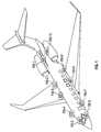
- FIG. 1 is a view of an aircraft 100 in which the disclosed embodiments can be implemented in accordance with one exemplary, non-limiting implementation.
- FIG. 1 illustrates that various nodes 150 can be located onboard the aircraft 100.
- FIG. 1 is intended to illustrate a conceptual representation of the nodes, but it should be appreciated that the nodes 150 can be located anywhere onboard the aircraft.
- the number and relative locations of the nodes 150 are non-limiting. In other words, any number of nodes 150 can be included within the aircraft 100 and the nodes can be mounted anywhere throughout the aircraft 100.
- the nodes 150 are part of a scalable integrated power distribution, data network, and control architecture that can be used to implement a distributed aircraft systems platform within the aircraft 100.
- the aircraft 100 may also include various other onboard computers, aircraft instrumentation, and additional control systems that are not illustrated for sake of clarity. Other features of nodes and the aircraft 100 will now be described below with reference to FIGS. 2 through 4 . As a preliminary matter, it is noted that in FIGS. 1 , 3 and 4 , some of the various primary power sources 140, primary power distribution units 142, sections of the power distribution lines 145, nodes 150, electrical loads 160, data elements 170, sections of data bus 180, and switches 190 are illustrated as being external to the aircraft.
- FIG. 2 is a block diagram that illustrates an exemplary node 150 in accordance with the disclosed embodiments.
- the node 150 is an integrated, multi-function component or unit.
- the node 150 includes a housing 205 that contains secondary power distribution (SPD) components including an electrical power input interface 210, a high-voltage power control module 220, one or more electrical power converter module(s) 230, low-voltage power control modules 240; a processor module 250 that performs a variety of processing and control functions; and data collection and distribution (DCD) components including a digital I/O interface module 260, an analog and discrete I/O interface module 270, and a high-bandwidth digital network I/O interface module 280.
- SPD secondary power distribution
- DCD data collection and distribution
- each of the modules can be separate pieces of equipment that are interconnected to each other without the use of wires external to the housing 205.
- each of the modules can be one or more electronic components installed on one or more circuit boards.
- a housing of a node can be a single container that encloses or encompasses all the components of a node, or modular containers that are mounted and interconnected to each other. To distinguish between the two implementations, the former will be referred to as a housing, and the latter will be referred to as a modular housing.
- Each of the various DCD interface modules 260, 270, 280 may include various hardware and software components that are not illustrated for sake of clarity.
- the electrical power input interface 210 is configured to be coupled to an electrical power source.
- the electrical power input interface 210 supplies electrical power that is distributed by the node 150 to electrical loads that consume electrical power and are located external to the node 150 and onboard the aircraft.
- the electrical power input interface 210 supplies high-voltage DC electrical power to the high-voltage power control module 220 and the electrical power converter module(s) 230.
- the electrical power input interface 210 is a single electrical power input interface that receives a high-voltage DC input, it should be appreciated that the electrical power input interface 210 can be of a different type (e.g., three phase AC), or include multiple redundant electrical power inputs from different sources.
- the node 150 serves as a secondary power distribution (SPD) unit that distributes electrical power to one or more electrical loads located external to the node and onboard the vehicle.
- SPD secondary power distribution
- the node 150 can be connected to one or more electric power sources via one or more electrical power input interfaces and supply electrical power to external loads that consume electrical power (e.g., actuators, motors, etc.) via one or more power output interfaces.
- the processor module 250 can represent at least one computer processor and associated computer memory that is either internal or external to the computer processor.
- the processor module 250 performs the computation and control functions of the node.
- a "computer processor” can refer to any type of conventional processor, controller, microcontroller, digital signal processor (DSP) or state machine.
- DSP digital signal processor
- a processor module can be implemented using a single computer processor or multiple computer processors that are not part of a single unit. Further, a processor module may comprise single integrated circuits such as a microprocessor, or any suitable number of multiple computer processors or integrated circuit devices and/or circuit boards working in cooperation to accomplish the functions of a processor module.
- a processor module is not necessarily implemented as a single discrete unit in all embodiments, but may also be implemented using a plurality of said computer processors that are distributed throughout the node.
- the computer memory may be a single type of memory component, or it may be composed of many different types of memory components.
- the memory may include non-volatile memory (such as ROM, flash memory, etc.), volatile memory (such as RAM), or some combination of the two.
- the RAM may be any type of suitable random access memory including the various types of dynamic random access memory (DRAM) such as SDRAM, the various types of static RAM (SRAM).
- DRAM dynamic random access memory
- SRAM static RAM
- the computer memory may contain an operating system, and executable code for power control programs, data conversion programs, or system control programs that can be loaded and executed at the processor module 250.
- the processor module 250 is configured to provide control signals to the high-voltage power control module 220 and the low-voltage power control modules 240, controlling the electrical power outputs of each.
- the processor module 250 generates the control signals (or "commands") that are communicated to high-voltage power control module 220 and the low-voltage power control modules 240 to control distribution of electrical power to various equipment or "loads" that are located throughout the aircraft 100 (as will be described in greater detail below with reference to FIG. 4 ).
- the DCD interfaces receive control signals that are generated by vehicle systems and subsystems that are external to the node (e.g.: Flight Control Computers, Flight Management Systems, control input devices activated by the driver or pilot), and one or more of the power control modules 220 and 240 supplies electrical power to electrical loads responsive to those external control signals.
- vehicle systems and subsystems e.g.: Flight Control Computers, Flight Management Systems, control input devices activated by the driver or pilot
- the high-voltage power control module 220 includes a number of electrical power outputs to individual electric power loads.
- the high-voltage power control module 220 can be implemented using a Solid State Power Controller (SSPC).
- the high-voltage power control module 220 includes electric power control elements capable of switching each electric power output from the high-voltage power control module 220 on or off in response to control signals received from the processor module 250. The control signals are illustrated via dashed lines in FIG. 2 .
- the high-voltage power control module 220 controls distribution of the high-voltage DC electrical power to external electrical loads that use or require high-voltage electrical power.
- FIG. 2 shows six outputs, it should be appreciated that the high-voltage power control module 220 can include any number of electrical power outputs needed based on the particular implementation of the node.
- the electrical power input interface 210 also supplies high-voltage DC electrical power to the electrical power converter modules 230.
- the electrical power converter module 230 can include one or more electrical power converters need to convert input received via the electrical power input interface 210 to the type of electrical power used by the electrical loads external to the node.
- an electrical power converter refers to hardware that is designed to receive an electrical power input via an electrical power interface and to convert the electrical power input to generate an electrical power output that is provided to one or more power control modules.
- the electrical power input can be any type of power input that is adequate for distribution, and that can be converted by the electrical power converter to any other type of electrical power that is used by external electrical loads.
- the electrical power converter can change a characteristic of the electrical power input to generate an electrical power output having different characteristics.
- the electrical power converter can change the waveform of the electrical power input to generate an electrical power output having different waveform.
- the electrical power converter can convert a DC electrical power input to an AC electrical power output, or vice-versa.
- the electrical power converter can convert the frequency of an AC electrical power input to an AC electrical power output having a different frequency.
- the electrical power converter can also change the voltage of the electrical power input to generate an electrical power output having different (higher or lower) voltage level.
- the electrical power converter module 230 can include elements such as transformers, rectifiers, and filters for converting a high-voltage DC input (received from the electrical power input interface 210) to a lower electrical power.
- the electrical power converter module 230 can include a step-down transformer to convert a high-voltage DC input (received from the electrical power input interface 210) to a low-voltage DC output.
- the electrical power converter module 230 can convert the high-voltage DC electrical power to a lower voltage DC electrical power (e.g., 28 volt DC), and provides the lower voltage DC electrical power to each low-voltage power control module 240.
- the low-voltage power control modules 240 control distribution of the lower voltage DC electrical power to external electrical loads that use or require low voltage electrical power.
- Each low-voltage power control module 240 provides electric power control elements capable of switching electric power that is output from that low-voltage power control module 240 on or off in response to control signals (illustrated via dashed lines in FIG. 2 ) received from the processor module 250.
- each low-voltage power control module 240 can be implemented using a Solid State Power Controller (SSPC).
- SSPC Solid State Power Controller
- Each low-voltage power control module 240 may include a number of electrical power outputs to individual electric power loads. Although each low-voltage power control module 240 of FIG. 2 shows six outputs, it should be appreciated that each low-voltage power control module 240 can include one or more electrical power outputs needed based on the particular implementation of the node 150.
- the electrical power converter module 230 can include additional electrical power converter(s), such as an inverter, for converting the high-voltage DC input from the electrical power input interface 210 to an AC voltage (not illustrated) that can then be supplied to an AC power control module (not shown). This way the node 150 can distribute both AC power and DC power to external loads.
- the electrical power converter(s) 230 can include transformer rectifiers to provide high or low voltage DC output to the high-voltage power control module 220 and low-voltage power control modules 240.
- the node 150 also serves as a data collection and distribution unit.
- the processor module 250 at each node can aggregate data received through the digital, analog and discrete I/O interface modules 260, 270, optionally process that data and then transmit the aggregated data through the high-bandwidth digital network interface module 280.
- the node 150 can be coupled to various data sources (e.g., sensors, control input devices and other types of equipment) using the digital I/O interface module 260 and the analog and discrete I/O interface module 270.
- the node 150 can then distribute data that is receives through these interface modules 260, 270 via a high-bandwidth digital network I/O interface module 280, or through the digital I/O interface module 260 and the analog and discrete I/O interface module 270 themselves.
- each processor module 250 can also receive data through the high-bandwidth digital network interface module 280, optionally process that data and then communicate that data through the appropriate digital, analog and discrete I/O interface modules 260, 270 for communication over an appropriate bus to intended data consumers (i.e., data elements that are data consumers).
- intended data consumers i.e., data elements that are data consumers.
- the digital I/O interface module 260 receives, from data sources or aircraft equipment, digital data that is compliant with digital bus standards, such as A429, CAN bus, MIL-STD-1553.
- the digital I/O interface module 260 can receive digital input signals communicated over a digital bus from data sources, and can communicate digital output signals over a digital bus to data consumers.
- the digital I/O interface module 260 is illustrated as a single block, it should be appreciated that the block labeled digital I/O interface module 260 can include one or more different types of digital I/O interfaces and associated hardware.
- the analog and discrete I/O interface module 270 receives discrete and/or analog data from data sources or aircraft equipment. Examples of such aircraft equipment include pressure sensors, temperature sensors, flow meters, proximity sensors or switches, etc.
- the analog and discrete I/O interface module 270 may be designed to receive one or more analog input signals and any type of discrete input data.
- the analog and discrete I/O interface module 270 can receive analog input signals communicated, for example, from a thermocouple.
- the analog and discrete I/O interface module 270 can receive discrete input data communicated, for example, from a position switch.
- the analog and discrete I/O interface module 270 can also communicate analog output signals to various types of electrically controlled actuators, and can also communicate discrete output data to solenoids, indicator lights and other low power electrical devices.
- analog and discrete I/O interface module 270 can include one or more different types of analog and discrete I/O interfaces and associated hardware.
- the analog and discrete I/O interface module 270 can also include associated analog-to-digital converters (ADCs) that convert analog input signals and discrete data into a digital format, and then communicate digital signals to the processor module 250 so that the processor does not have to perform this conversion.
- ADCs analog-to-digital converters
- the analog and discrete I/O interface module 270 can also include digital-to-analog converters (DACs) and output drivers need to convert data from the processor module 250 to generate any number of analog output signals.
- DACs digital-to-analog converters
- the data transmitted by the node 150 through the high-bandwidth digital network I/O interface module 280 may be routed to other nodes 150 directly, or using network switches (as will be described in greater detail below with reference to FIG. 4 ).
- the data conversion performed by the node 150 may be defined by configuration files that define the data source of particular data, a data consumer for that particular data, and instructions for how that particular data needs to be processed and re-formatted prior to sending it through the appropriate interface module toward the intended data consumer.
- the high-bandwidth digital network I/O interface module 280 allows the node 150 to be connected directly or via network switches to other nodes 150, Integrated Modular Avionics (IMA) units, or other electronic equipment onboard the aircraft.
- IMA Integrated Modular Avionics
- FIG. 2 the high-bandwidth digital network I/O interface module 280 is illustrated as a single block. However, the high-bandwidth digital network I/O interface module 280 can represent more than one high speed network interface and associated hardware. Additionally, in FIG. 2 , the high-bandwidth digital network I/O interface module 280 is illustrated connected to dedicated output wires. However, in another embodiment the high-bandwidth digital network I/O interface module could transmit and receive information using the same wire or wires connected to the power input interface 210 ("data over power").
- the high-bandwidth digital network I/O interface module 280 includes at least one high-bandwidth network interface that is designed to communicate data over a bus (not illustrated in FIG. 2 ).
- the high-bandwidth digital network I/O interface module 280 can be designed for communication in accordance with one or more high-bandwidth bus protocols such as Ethernet, A664, AFDX, etc.
- the high-bandwidth digital network I/O interface module 280 communicates the concentrated data over a bus (not shown in FIG. 2 ) to network switches, other nodes 150 (not shown in FIG. 2 ), or other electronic equipment external to the node 150 (not shown in V).
- the high-bandwidth digital network I/O interface module 280 can also receive data that is communicated from network switches, other nodes 150, or other electronic equipment external to the node 150.
- FIGS. 3 and 4 are diagrams that illustrate different aspects of an integrated power distribution, data network, and control architecture that can be used in an aircraft 100 to provide a distributed aircraft systems platform.
- FIGS. 3 and 4 are depictions of the same integrated system, but are illustrated in separate drawings that focus on different features provided via nodes 150 that are part of the integrated power distribution, data network, and control architecture.
- FIG. 3 is a diagram that illustrates the power distribution aspect of the distributed aircraft systems platform
- FIG. 4 is a diagram that illustrates the data network aspect of the distributed aircraft systems platform.
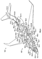
- FIG. 3 is a simplified diagram of an aircraft power distribution network 300 in accordance with one implementation of the disclosed embodiments.
- the aircraft 100 includes right-side primary power source (PPS) 140-1, a left-side primary power source (PPS) 140-2, a right-side primary power distribution (PPD) Unit 142-1, a left-side primary power distribution (PPD) Unit 142-2, and nodes 150 that are distributed throughout the aircraft.
- PPS right-side primary power source
- PPS left-side primary power source
- PPD right-side primary power distribution
- PPD left-side primary power distribution
- Unit 142-2 nodes 150 that are distributed throughout the aircraft.
- each PPS 140 is connected through a PPD unit 142 to a number of nodes 150 that are distributed throughout the aircraft.
- Each PPS can be any primary source of electrical power that is external to the nodes, and can vary depending on the implementation.
- each PPS can be implemented using a constant frequency AC generator.
- each PPS can be implemented using a variable frequency AC generator (e.g., generator coupled directly with the engine such that the frequency varies with engine speed).
- the PPD unit 142 connects a PPS to multiple secondary power distribution (SPD) units, including nodes 150, and may additionally include switching or power conversion capabilities.
- SPD secondary power distribution
- the electrical power output by the PPS can be relatively high-voltage AC electrical power that is transmitted directly to the nodes 150 and is converted to DC electrical power by the electrical power converter modules 230 in the nodes 150.
- each PPD unit can include an AC-DC converter such that the AC electrical power output by the PPS can be converted to relatively high-voltage DC electrical power that is distributed to the nodes.
- Each node 150 is coupled to one of the PPD units 142 via a power distribution line 145 that carries electrical power to that node.
- the aircraft 100 includes five nodes 150-1...150-5 on the right-side of the aircraft 100, and five nodes 150-6...150-10 on the left-side of the aircraft 100.
- this is only for purposes of illustrating one possible implementation and that the aircraft 100 can include any number of nodes 150 in any arrangement depending on the implementation.
- Each node 150 is coupled to at least one electrical load 160.
- the electrical loads are represented by small rectangles and labeled with reference number 160.
- an electrical load refers to any equipment on the aircraft that consumes electric power. Non-limiting examples of such equipment can include: motors, actuators, valves, lights, heaters, sensors, displays, cabin amenities, galley amenities, computers, processors, or any other device, component, or unit that consumes electrical power.
- the aircraft 100 includes eleven rectangles that represent electrical loads 160-1...160-11 on the right-side of the aircraft 100, and eleven rectangles that represent electrical loads 160-12...160-22 on the left-side of the aircraft 100.
- the aircraft 100 can include one or more electrical loads 160 depending on the implementation.
- the nodes 150 may be used to power all the electrical loads 160 on the aircraft (as illustrated in FIG.3 ) or only part of them, with the remainder powered by traditional means.
- FIG. 3 illustrates that each node 150 serves as a secondary power distribution (SPD) unit that distributes electrical power to at least one electrical load 160.
- SPD secondary power distribution
- Each node 150 is capable of converting electrical power received from a PPD unit 142 into a form that can be used by each of the individual electrical loads 160 that it is coupled to, and controlling distribution of electrical power to each of those individual electrical loads 160. For example, some electrical loads may consume direct current (DC) electrical power, whereas other electrical loads may consume alternating current (AC) electrical power.
- DC direct current
- AC alternating current
- some electrical loads can be designed to receive lower DC electrical power (e.g., 28 Volts), other electrical loads can be designed to receive higher DC electrical power (e.g., 270 Volts), while still other electrical loads can be designed to receive AC electrical power that has a low-voltage or a higher voltage (e.g., 115 volts).
- the frequency can vary. For instance, some electrical loads may require AC electrical power having a frequency of 400 Hertz, while other electrical loads may require AC electrical power having a frequency of 60 Hertz.
- the processor module 250 in each node 150 can host logic to perform a wide variety of functions.
- the processor module 250 can monitor electrical characteristics (e.g., current, voltage, frequency) of the electrical power supplied to the one or more electrical loads and detect, based on the electrical characteristics, abnormal conditions.
- abnormal conditions can include, for example, permanent or intermittent short circuit conditions, abnormal voltage conditions such as over voltage or under voltage, abnormal electric power quality (e.g., as determined by monitoring input or output waveform, frequency, phase, current, and/or voltage), and/or other fault conditions that reflect other undesirable or potentially unsafe conditions.
- FIG. 4 is a simplified block diagram of an aircraft data network 400 that can be implemented using the nodes 150 in accordance with one non-limiting implementation of the disclosed embodiments. Similar to the FIG. 3 depiction of electrical loads, FIG. 4 illustrates that the aircraft can include a plurality of data elements 170 (represented by small circles located throughout the aircraft), data buses 180, and network switches 190. It is to be appreciated that the implementation illustrated in FIG. 4 is non-limiting that that any number of nodes 150, data elements 170, data busses 180 and network switches 190 can be included in other implementations. In the embodiment that is illustrated in FIG. 4 , the network switches 190 are shown as distinct or dedicated devices that are separate from the nodes.
- the network switches 190 effectively act as a centralized hub that is part of a star network topology.
- FIG. 4 represents one particular, non-limiting implementation in which switching functionality of the network switches 190 is implemented separately and externally from the nodes 150. It should be appreciated that the switching functionality of the network switches 190 can be implemented using the processor module 250 within each node in other embodiments. This allows the nodes to form other network topologies, for example a mesh, ring, or daisy chain network topology.
- Data elements 170 can represent data sources and/or data consumers that are external to the nodes. Some data elements are sources of data, but do not consume data, some data elements are consumers of data, but are not sources of data, and some data elements are both data sources and data consumers.
- a data source is a transmitting system that transmits data, whereas a data consumer is a receiving system that receives data. Data sources and data consumers will be discussed in greater detail below.
- each node 150 can be communicatively coupled to at least one network switch 190 via a data bus 180.
- Each network switch 190 can be communicatively coupled to nodes 150 and/or other network switches 190 via a data bus 180.
- the data bus 180 can be high bandwidth digital bus such as one that is compliant with ARINC-664.
- the term "network switch" can refer to a networking device that connects two or more aircraft systems (e.g., nodes or other devices) together and performs switching functions with respect to data communicated between those systems.
- a network switch receives incoming data, determines its destination, and forwards the processed data along a path towards its intended destination.
- each network switch is configured to: read translated data, determine its destination and a path to that destination (e.g., a particular data element that is a consumer of that data), and route the translated data along a path towards the appropriate destination.
- Each node 150 can receive incoming signals from any number of different data elements 170 that serve as data sources. In other words, each node 150 receives data from any data elements 170 that are data sources.
- the different incoming signals can be in a variety of forms (e.g., discrete, analog, digital).
- Each node can also receive incoming signals from other nodes via the data bus 180 and network switches 190, and can then distribute this data to any number of different data elements 170 that are data consumers.
- each node 150 is configured to serve as a data collection and distribution unit that is capable of receiving data from data elements 170 and communicating data to other data elements 170.
- each node 150 can "concentrate" the data received from data elements 170 that are data sources, and communicate or distribute the concentrated data over the data bus 180 to a network switch 190.
- the network switch 190 then routes data toward various destinations or end points.
- the network switch 190 then routes data to other nodes 150 that it is coupled to or to another network switch 190 that it is coupled to so that the data moves along an appropriate path to its destination or data elements 170 that are the intended data consumers of that data.
- each node 150 can convert input data from one form to another before outputting it. For instance, each node 150 can receive input data (in discrete, analog or digital form) from a variety of different data elements and can process and reformat the input data into one or more digital data formats so that it can be communicated over one or more networks.
- a node 150 may act as a protocol converter that can convert incoming input signals per an incoming network protocol (e.g.: EIA/TIA-232, EIA/TIA-422, EIA/TIA-485, ARINC 429, USB 2.0, ARINC-664, MIL-STD-1553, CAN bus, Ethernet) to a different protocol or protocols for retransmission.
- each node 150 can receive data per an incoming network protocol, and convert the data back into a variety of forms that is useable by the various data elements that are data consumers before communicating to those data elements (i.e., translate or reformat the network data into the data forms needed or used by each particular data consumer element connected to the node 150).
- Data elements 170 that are data sources can include, for example, inertial reference systems (IRSs), attitude heading and reference systems (AHRSs), air data systems (ADSs), communication systems, Global Position System (GPS) receivers, Global Navigation Satellite System (GNSS) interfaces, other wireless interfaces, sensors, such as motion sensors, accelerometers, position sensors, pressure sensors, temperature sensors, gyroscopes, magnetic compasses, navigation instrument sensors, speed sensors, angular rate sensors, position, angle, displacement, distance, speed, or acceleration sensors (e.g., accelerometers, inclinometers, position sensors, position switches, rotary encoders, resolvers, rotary/linear variable differential transformers, tachometers, etc.), acoustic sensors (e.g., sound, microphone, seismometer, accelerometer, etc.), vibration sensors, cameras, radars, etc.
- the data provided from the data sources can be discrete data, analog data, or digital data.
- Data elements 170 that are data consumers can include, for example, avionics systems, communications systems, navigation systems, surveillance systems, monitoring systems, control systems, control panels, aircraft flight-control systems, collision-avoidance systems, aircraft management systems, radar systems, displays (e.g., control display units, multifunction displays (MFDs), standby displays), warning systems, flight control computers that are used to control the aircraft's control surfaces (e.g., ailerons, elevators, rudder, spoilers, flaps), engine controllers, APU controllers, and any other destination receiving systems that receive data.
- the data provided to the data consumers can be discrete data, analog data, or digital data.
- the processor module 250 of each node 150 can host logic for performing a number of different functions that are traditionally performed by dedicated controllers, units and systems that are traditionally distributed throughout the vehicle.
- non-limiting examples of these functions performed by the processor can include: processing sensor data that would conventionally be hosted at one or more controllers of an air data system; processing logic for pressure control, temperature control, flow control, and overheat detection that would conventionally be hosted at one or more controllers of a bleed air system; processing logic for fire protection, detection and suppression that would conventionally be hosted at one or more controllers of a fire protection system; processing logic for landing gear extension and retraction, landing gear position indication, and weight on wheels detection that would conventionally be hosted at a landing gear control unit of a landing gear system; processing logic for cabin environmental control (e.g., temperature, pressure, ventilation, humidity) that would conventionally be hosted at one or more controllers of an environmental control system (ECS); processing logic for cabin pressurization control that would conventionally be hosted at one or more controllers of a pressurization control system; processing logic for ice prevention or removal that would conventionally be hosted at one or more controllers of an ice protection system; processing logic for engine control and indication that would conventional
- an aircraft is usually designed to include two or more redundant versions of each critical system component.
- nodes 150-1 through 150-5, data bus 180-1 and switches 190-1, 190-2 are equipment that make up a first data network that is located the left-side of the aircraft 100
- nodes 150-6 through 150-10, data bus 180-2 and switches 190-3, 190-4 are equipment that make up a second data network that is located on the right-side of the aircraft 100
- two or more data networks may perform different functions from each other.
- the data networks are simply distinct data networks used for different purposes.
- two or more data networks may be identical to each other to provide a measure of redundancy in the event that one of the data networks (or a component thereof) experiences a fault. For instance, if one of the nodes 150-1 through 150-5, or part of the data bus 180-1 or one of the switches 190-1, 190-2 that make up the first data network the left-side of the aircraft 100 experience a fault condition, but the second data network does not, then the second data network could still be utilized to accomplish the same or equivalent functionality as the first data network. However, in this case a situation could arise where all of the nodes 150 or all of the switches 190 experienced a common mode of fault (e.g., an unforeseen software glitch or common hardware fault).
- a common mode of fault e.g., an unforeseen software glitch or common hardware fault.
- two or more data networks can be functionally similar to each other, providing redundancy, but can be implemented using different hardware and/or software so that the data networks can transport data over independent paths that are not susceptible to common modes of fault.
- one data network can include network switches, data buses and nodes that employ different hardware and/or software in comparison to the network switches, data buses and nodes that are implemented within another data network.
- each network on the aircraft 100 includes additional sets of nodes, additional data buses and additional switches so that redundant data paths are provided within the first data network and the second data network of the aircraft 100.
- a second separate data path may be provided within the first data network and within the second data network to provide separate, alternative pathways for data that is communicated between the various data elements on each network. This way there can be alternative communication paths (or multiple distinct pathways) for communicating data between the data elements (and any other systems that are a source of or that consume that data).
- each path can include different hardware and/or software components that are dissimilar but still perform similar functions in different ways.
- This dissimilarity helps ensure that the analogous components (e.g., nodes or network switches) in each path are not necessarily subject to the same fault modes or operational errors.
- corresponding components are not subject to the same fault modes (e.g., software glitches or bugs, hardware failures, or software or hardware design errors not discovered in verification testing). This can help reduce and/or eliminate the risk of common mode faults.
- the aircraft's functions that rely on critical data will have at least two sources for that critical data, and each of the two sources will transport that critical data over different, dissimilar paths.
- a plurality of nodes can be distributed throughout a vehicle, such as an aircraft, and used to create a single integrated systems platform capable of distributed data acquisition and transmission, both distributed and centralized control processing, and power distribution and control.
- the network of nodes can replace modular power tiles (MPTs), remote data concentrators (RDCs), dedicated system control units, modular avionics units (MAUs), and the current multiplicity of digital networks to simultaneously provide secondary power distribution, data networking, and system control with the level of redundancy appropriate to the application.
- the disclosed embodiments can allow for replacement of most or all system controllers, central computers, data concentration devices and networks and secondary power distribution systems with a single highly-redundant, scalable, and flexible distributed aircraft systems platform.
- system capabilities and resources can be more efficiently utilized, and significant reductions in weight and installation and maintenance complexity can be achieved.
- the distributed aircraft systems platform improves systems integration by combining a distributed control and data network with power distribution and switching, and system control capability. Instead of having federated or integrated controllers signaling a separate power distribution system, the distributed systems platform integrates both these roles, eliminating unnecessary wiring interconnection.
- the distributed systems platform can also allow higher robustness to localized damage or failure, due to the increased ability to perform functions locally even when the remote processing and data sources may be unavailable. This is due to the fact that the distributed systems platform contains data input/output, power distribution and processing capability distributed throughout the aircraft.
- the distributed systems platform can also reduce manufacturing and maintenance costs.
- Skilled artisans may implement the described functionality in varying ways for each particular application, but such implementation decisions should not be interpreted as causing a departure from the scope of the present invention.
- an embodiment of a system or a component may employ various integrated circuit components, e.g., memory elements, digital signal processing elements, logic elements, look-up tables, or the like, which may carry out a variety of functions under the control of one or more microprocessors or other control devices.
- integrated circuit components e.g., memory elements, digital signal processing elements, logic elements, look-up tables, or the like, which may carry out a variety of functions under the control of one or more microprocessors or other control devices.
- DSP digital signal processor
- ASIC application specific integrated circuit
- FPGA field programmable gate array
- a general-purpose processor may be a microprocessor, but in the alternative, the processor may be any conventional processor, controller, microcontroller, or state machine.
- a processor may also be implemented as a combination of computing devices, e.g., a combination of a DSP and a microprocessor, a plurality of microprocessors, one or more microprocessors in conjunction with a DSP core, or any other such configuration.
- a software module may reside in RAM memory, flash memory, ROM memory, EPROM memory, EEPROM memory, registers, hard disk, a removable disk, a CD-ROM, or any other form of storage medium known in the art.
- An exemplary storage medium is coupled to the processor such the processor can read information from, and write information to, the storage medium.
- the storage medium may be integral to the processor.
- the processor and the storage medium may reside in an ASIC.
Applications Claiming Priority (1)
| Application Number | Priority Date | Filing Date | Title |
|---|---|---|---|
| US14/878,904 US10065583B2 (en) | 2015-10-08 | 2015-10-08 | Integrated power distribution, data network, and control architectures for a vehicle |
Publications (1)
| Publication Number | Publication Date |
|---|---|
| EP3154151A1 true EP3154151A1 (fr) | 2017-04-12 |
Family
ID=57389167
Family Applications (1)
| Application Number | Title | Priority Date | Filing Date |
|---|---|---|---|
| EP16192280.2A Withdrawn EP3154151A1 (fr) | 2015-10-08 | 2016-10-04 | Distribution de puissance, réseau de données et architectures de commande intégrés dans un véhicule |
Country Status (5)
| Country | Link |
|---|---|
| US (1) | US10065583B2 (fr) |
| EP (1) | EP3154151A1 (fr) |
| CN (1) | CN106569436A (fr) |
| BR (1) | BR102016023396A2 (fr) |
| CA (1) | CA2942326A1 (fr) |
Cited By (7)
| Publication number | Priority date | Publication date | Assignee | Title |
|---|---|---|---|---|
| EP3388793A1 (fr) * | 2017-04-13 | 2018-10-17 | Liebherr-Aerospace Lindenberg GmbH | Module électronique pour appareils périphériques d'un aéronef |
| EP3407448A1 (fr) * | 2017-05-23 | 2018-11-28 | Simmonds Precision Products, Inc. | Dispositif de régulation pour systèmes de capteurs distribués |
| EP3462636A1 (fr) * | 2017-09-27 | 2019-04-03 | The Boeing Company | Systèmes et procédés de connectivité d'équipage d'avion |
| EP3503338A1 (fr) * | 2017-12-19 | 2019-06-26 | Hamilton Sundstrand Corporation | Architecture multiniveau hiérarchique pour systèmes de distribution d'énergie |
| DE102018205291A1 (de) * | 2018-04-09 | 2019-10-10 | Airbus Operations Gmbh | Kontrollsystem für die Kabine eines Luftfahrzeugs, Datenverteilungsvorrichtung und Luftfahrzeug |
| US11412374B2 (en) | 2017-09-27 | 2022-08-09 | The Boeing Company | Aircraft interface device |
| EP3920470A4 (fr) * | 2019-01-31 | 2022-09-07 | Kabushiki Kaisha Yaskawa Denki | Système de communication et connecteur |
Families Citing this family (19)
| Publication number | Priority date | Publication date | Assignee | Title |
|---|---|---|---|---|
| US10202088B2 (en) * | 2016-01-15 | 2019-02-12 | Hamilton Sundstrand Corporation | Combined remote sensing, processing, and solid state power control system |
| US10129143B2 (en) * | 2016-10-25 | 2018-11-13 | The Boeing Company | Bandwidth on deterministic aircraft data networks |
| FR3063187B1 (fr) * | 2017-02-22 | 2022-03-25 | Latecoere | Procede et architecture de distribution de puissance embarquee dans un aeronef |
| DE102017205535B4 (de) * | 2017-03-31 | 2024-03-07 | Airbus Operations Gmbh | Schnittstellenarchitektur, Kabinenmonument und Verfahren zur Anbindung eines Kabinenmonuments in einem Flugzeug |
| FR3068532A1 (fr) * | 2017-06-29 | 2019-01-04 | Zodiac Aero Electric | Boitier de distribution d'energie electrique pour reseau de bord d'un aeronef et systeme d'alimentation electrique correspondant |
| EP3439244B1 (fr) * | 2017-08-02 | 2019-09-18 | Airbus Operations S.A.S. | Elément modulaire pour un réseau mixte d'un aéronef |
| US10848341B2 (en) * | 2017-08-02 | 2020-11-24 | Airbus Operations Sas | Aircraft comprising a hybrid electrical power distribution and data communication network |
| CN108155816A (zh) * | 2017-10-23 | 2018-06-12 | 中国商用飞机有限责任公司北京民用飞机技术研究中心 | 一种飞机配电系统及方法 |
| DE102017130447B4 (de) * | 2017-12-19 | 2019-10-02 | Airbus Defence and Space GmbH | Netzwerkmodul und Netzwerkanordnung |
| US10795668B2 (en) | 2017-12-20 | 2020-10-06 | Hamilton Sundstrand Corporation | Software version synchronization for avionics systems |
| US10604136B1 (en) * | 2018-03-29 | 2020-03-31 | SBS, Incorporated | Parking brake alarm systems |
| CN108712060A (zh) * | 2018-04-20 | 2018-10-26 | 中国商用飞机有限责任公司北京民用飞机技术研究中心 | 一种远程变换配电装置 |
| US20200217253A1 (en) * | 2019-01-03 | 2020-07-09 | General Electric Company | Systems and Methods of Controlling Load Share and Speed of Engines in Multiple-Engine Propulsion Systems |
| CN110139243B (zh) * | 2019-03-06 | 2022-05-27 | 北京车和家信息技术有限公司 | 车辆监测方法、监测终端、车辆监测系统及介质 |
| US11533080B2 (en) | 2019-09-27 | 2022-12-20 | Gulfstream Aerospace Corporation | System and methods of employing data over power in aircraft |
| CN111144061A (zh) * | 2019-12-02 | 2020-05-12 | 凯里学院 | 一种在线性电路中电源功率分解的方法 |
| US11535112B2 (en) * | 2020-09-10 | 2022-12-27 | Motional Ad Llc | Managing power of electronic devices on a vehicle |
| CN112086966B (zh) * | 2020-09-11 | 2022-03-01 | 上海施耐德电气电力自动化有限公司 | 一种开关模拟系统 |
| CN114609953B (zh) * | 2022-04-13 | 2024-03-26 | 中国第一汽车股份有限公司 | 一种融合车控控制器系统及车辆 |
Citations (4)
| Publication number | Priority date | Publication date | Assignee | Title |
|---|---|---|---|---|
| US20050136989A1 (en) * | 2003-12-12 | 2005-06-23 | Dove Daniel J. | Method and system for distributing power to networked devices |
| WO2009052447A2 (fr) * | 2007-10-17 | 2009-04-23 | V2Green, Inc. | Interface utilisateur et commande utilisateur dans un système d'agrégation de puissance pour ressources électriques réparties |
| US20100198713A1 (en) * | 2007-08-28 | 2010-08-05 | Forbes Jr Joseph W | System and method for manipulating controlled energy using devices to manage customer bills |
| US8447434B1 (en) * | 2011-01-26 | 2013-05-21 | Williams-Pyro, Inc. | System and method of dynamic and distributed control with topology discovery in an isolated power grid |
Family Cites Families (5)
| Publication number | Priority date | Publication date | Assignee | Title |
|---|---|---|---|---|
| CN1878038A (zh) * | 2005-06-07 | 2006-12-13 | 洛克威尔自动控制技术股份有限公司 | 无线模块化监视和保护系统拓扑结构 |
| CN100403622C (zh) * | 2006-09-01 | 2008-07-16 | 桂林航天电子有限公司 | 智能配电管理中心 |
| GB2468652B (en) * | 2009-03-16 | 2011-08-31 | Ge Aviat Systems Ltd | Electrical power distribution |
| CN104470602B (zh) * | 2012-11-06 | 2018-11-20 | 克萨公司 | 远程控制系统和方法及与这种系统相关的使用 |
| US9183983B2 (en) * | 2013-10-11 | 2015-11-10 | The Boeing Company | Modular equipment center integrated truss sensors |
-
2015
- 2015-10-08 US US14/878,904 patent/US10065583B2/en active Active
-
2016
- 2016-09-19 CA CA2942326A patent/CA2942326A1/fr not_active Abandoned
- 2016-10-04 EP EP16192280.2A patent/EP3154151A1/fr not_active Withdrawn
- 2016-10-07 BR BR102016023396A patent/BR102016023396A2/pt not_active Application Discontinuation
- 2016-10-08 CN CN201610878867.6A patent/CN106569436A/zh active Pending
Patent Citations (4)
| Publication number | Priority date | Publication date | Assignee | Title |
|---|---|---|---|---|
| US20050136989A1 (en) * | 2003-12-12 | 2005-06-23 | Dove Daniel J. | Method and system for distributing power to networked devices |
| US20100198713A1 (en) * | 2007-08-28 | 2010-08-05 | Forbes Jr Joseph W | System and method for manipulating controlled energy using devices to manage customer bills |
| WO2009052447A2 (fr) * | 2007-10-17 | 2009-04-23 | V2Green, Inc. | Interface utilisateur et commande utilisateur dans un système d'agrégation de puissance pour ressources électriques réparties |
| US8447434B1 (en) * | 2011-01-26 | 2013-05-21 | Williams-Pyro, Inc. | System and method of dynamic and distributed control with topology discovery in an isolated power grid |
Cited By (12)
| Publication number | Priority date | Publication date | Assignee | Title |
|---|---|---|---|---|
| EP3388793A1 (fr) * | 2017-04-13 | 2018-10-17 | Liebherr-Aerospace Lindenberg GmbH | Module électronique pour appareils périphériques d'un aéronef |
| EP3407448A1 (fr) * | 2017-05-23 | 2018-11-28 | Simmonds Precision Products, Inc. | Dispositif de régulation pour systèmes de capteurs distribués |
| US10595430B2 (en) | 2017-05-23 | 2020-03-17 | Simmonds Precision Products, Inc. | Regulator unit for distributed sensor systems |
| EP3462636A1 (fr) * | 2017-09-27 | 2019-04-03 | The Boeing Company | Systèmes et procédés de connectivité d'équipage d'avion |
| US10764753B2 (en) | 2017-09-27 | 2020-09-01 | The Boeing Company | Flight crew connectivity systems and methods |
| US11412374B2 (en) | 2017-09-27 | 2022-08-09 | The Boeing Company | Aircraft interface device |
| EP3503338A1 (fr) * | 2017-12-19 | 2019-06-26 | Hamilton Sundstrand Corporation | Architecture multiniveau hiérarchique pour systèmes de distribution d'énergie |
| US10779430B2 (en) | 2017-12-19 | 2020-09-15 | Hamilton Sundstrand Corporation | Multilevel hierarchical architecture for power distribution systems |
| DE102018205291A1 (de) * | 2018-04-09 | 2019-10-10 | Airbus Operations Gmbh | Kontrollsystem für die Kabine eines Luftfahrzeugs, Datenverteilungsvorrichtung und Luftfahrzeug |
| US11203441B2 (en) | 2018-04-09 | 2021-12-21 | Airbus Operations Gmbh | Monitoring system for the cabin of an aircraft, data distribution apparatus and aircraft |
| EP3920470A4 (fr) * | 2019-01-31 | 2022-09-07 | Kabushiki Kaisha Yaskawa Denki | Système de communication et connecteur |
| US11956092B2 (en) | 2019-01-31 | 2024-04-09 | Kabushiki Kaisha Yaskawa Denki | Communication system and connector |
Also Published As
| Publication number | Publication date |
|---|---|
| CN106569436A (zh) | 2017-04-19 |
| CA2942326A1 (fr) | 2017-04-08 |
| BR102016023396A2 (pt) | 2017-05-23 |
| US20170101067A1 (en) | 2017-04-13 |
| US10065583B2 (en) | 2018-09-04 |
Similar Documents
| Publication | Publication Date | Title |
|---|---|---|
| US10065583B2 (en) | Integrated power distribution, data network, and control architectures for a vehicle | |
| US9838436B2 (en) | Aircraft data networks | |
| US11220288B2 (en) | Method and device for the control of a safety-relevant process and transportation vehicle | |
| US8275494B1 (en) | System, apparatus and method for controlling an aircraft | |
| US10875511B2 (en) | Systems and methods for brake redundancy for an autonomous vehicle | |
| US9221538B2 (en) | Flight control system for unmanned aerial vehicle | |
| CN203786564U (zh) | 一种双余度飞行控制系统 | |
| CN104950740B (zh) | 具有冗余计算机的用于交通工具的系统 | |
| EP3516469B2 (fr) | Système de commande de véhicule | |
| US10663964B2 (en) | Unified and redundant flight and mission control for an unmanned aerial vehicle | |
| JP2009523658A (ja) | 分散型飛行制御システムのバックアップ制御のための装置及び方法 | |
| EP3210889A1 (fr) | Système de réglage de pression de cabine d'aéronef sans fil au moyen de capteurs de pression intelligents | |
| CN108693793B (zh) | 飞行器飞行控制系统和飞行器 | |
| WO2019058962A1 (fr) | Système de commande pour corps mobile et procédé de commande pour corps mobile | |
| ES2955474T3 (es) | Sistema para el funcionamiento de una embarcación equipada con un motor eléctrico | |
| RU2592193C1 (ru) | Интегрированный комплекс бортового оборудования разнородной архитектуры | |
| US11528165B2 (en) | Remote sensor data acquisition | |
| US20140156120A1 (en) | Monitoring and failover operation within locomotive distributed control system | |
| US10829211B2 (en) | Local digital conversion for force and position signals for electric actuation control | |
| CN216748542U (zh) | 无人机自驾仪系统 | |
| US11677473B2 (en) | Hybrid wire-fiber data networks for electromagnetic and/or ground-noise environments, components thereof, and systems incorporating same | |
| US20230286451A1 (en) | Vehicle interface system and/or method | |
| EP4178062A1 (fr) | Systèmes et procédés de transfert d'énergie et de gestion de charge | |
| EP3153364B1 (fr) | Robustesse accrue et disponibilité d'évaluation d'accélération d'aéronef | |
| US20230227174A1 (en) | Simplex flight control computer to be used in a flight control system |
Legal Events
| Date | Code | Title | Description |
|---|---|---|---|
| PUAI | Public reference made under article 153(3) epc to a published international application that has entered the european phase |
Free format text: ORIGINAL CODE: 0009012 |
|
| STAA | Information on the status of an ep patent application or granted ep patent |
Free format text: STATUS: THE APPLICATION HAS BEEN PUBLISHED |
|
| AK | Designated contracting states |
Kind code of ref document: A1 Designated state(s): AL AT BE BG CH CY CZ DE DK EE ES FI FR GB GR HR HU IE IS IT LI LT LU LV MC MK MT NL NO PL PT RO RS SE SI SK SM TR |
|
| AX | Request for extension of the european patent |
Extension state: BA ME |
|
| STAA | Information on the status of an ep patent application or granted ep patent |
Free format text: STATUS: REQUEST FOR EXAMINATION WAS MADE |
|
| 17P | Request for examination filed |
Effective date: 20171012 |
|
| RBV | Designated contracting states (corrected) |
Designated state(s): AL AT BE BG CH CY CZ DE DK EE ES FI FR GB GR HR HU IE IS IT LI LT LU LV MC MK MT NL NO PL PT RO RS SE SI SK SM TR |
|
| STAA | Information on the status of an ep patent application or granted ep patent |
Free format text: STATUS: EXAMINATION IS IN PROGRESS |
|
| 17Q | First examination report despatched |
Effective date: 20190515 |
|
| STAA | Information on the status of an ep patent application or granted ep patent |
Free format text: STATUS: THE APPLICATION IS DEEMED TO BE WITHDRAWN |
|
| 18D | Application deemed to be withdrawn |
Effective date: 20200728 |