EP3154109A1 - Battery element comprising a plurality of battery cells disposed in a line - Google Patents
Battery element comprising a plurality of battery cells disposed in a line Download PDFInfo
- Publication number
- EP3154109A1 EP3154109A1 EP15802465.3A EP15802465A EP3154109A1 EP 3154109 A1 EP3154109 A1 EP 3154109A1 EP 15802465 A EP15802465 A EP 15802465A EP 3154109 A1 EP3154109 A1 EP 3154109A1
- Authority
- EP
- European Patent Office
- Prior art keywords
- cells
- terminals
- board
- printed circuit
- tracks
- Prior art date
- Legal status (The legal status is an assumption and is not a legal conclusion. Google has not performed a legal analysis and makes no representation as to the accuracy of the status listed.)
- Withdrawn
Links
- 238000003466 welding Methods 0.000 claims description 4
- 230000000295 complement effect Effects 0.000 claims description 3
- 238000000034 method Methods 0.000 description 4
- 238000002485 combustion reaction Methods 0.000 description 1
- 230000001419 dependent effect Effects 0.000 description 1
- 239000007789 gas Substances 0.000 description 1
- 230000010354 integration Effects 0.000 description 1
- 231100000518 lethal Toxicity 0.000 description 1
- 230000001665 lethal effect Effects 0.000 description 1
- 239000011159 matrix material Substances 0.000 description 1
- 238000012986 modification Methods 0.000 description 1
- 230000004048 modification Effects 0.000 description 1
- 230000008520 organization Effects 0.000 description 1
- 230000001105 regulatory effect Effects 0.000 description 1
- 239000000126 substance Substances 0.000 description 1
Images

Classifications
-
- H—ELECTRICITY
- H01—ELECTRIC ELEMENTS
- H01M—PROCESSES OR MEANS, e.g. BATTERIES, FOR THE DIRECT CONVERSION OF CHEMICAL ENERGY INTO ELECTRICAL ENERGY
- H01M50/00—Constructional details or processes of manufacture of the non-active parts of electrochemical cells other than fuel cells, e.g. hybrid cells
- H01M50/50—Current conducting connections for cells or batteries
- H01M50/502—Interconnectors for connecting terminals of adjacent batteries; Interconnectors for connecting cells outside a battery casing
- H01M50/519—Interconnectors for connecting terminals of adjacent batteries; Interconnectors for connecting cells outside a battery casing comprising printed circuit boards [PCB]
-
- H—ELECTRICITY
- H01—ELECTRIC ELEMENTS
- H01M—PROCESSES OR MEANS, e.g. BATTERIES, FOR THE DIRECT CONVERSION OF CHEMICAL ENERGY INTO ELECTRICAL ENERGY
- H01M10/00—Secondary cells; Manufacture thereof
- H01M10/42—Methods or arrangements for servicing or maintenance of secondary cells or secondary half-cells
- H01M10/4207—Methods or arrangements for servicing or maintenance of secondary cells or secondary half-cells for several batteries or cells simultaneously or sequentially
-
- H—ELECTRICITY
- H01—ELECTRIC ELEMENTS
- H01M—PROCESSES OR MEANS, e.g. BATTERIES, FOR THE DIRECT CONVERSION OF CHEMICAL ENERGY INTO ELECTRICAL ENERGY
- H01M10/00—Secondary cells; Manufacture thereof
- H01M10/42—Methods or arrangements for servicing or maintenance of secondary cells or secondary half-cells
- H01M10/48—Accumulators combined with arrangements for measuring, testing or indicating the condition of cells, e.g. the level or density of the electrolyte
- H01M10/486—Accumulators combined with arrangements for measuring, testing or indicating the condition of cells, e.g. the level or density of the electrolyte for measuring temperature
-
- H—ELECTRICITY
- H01—ELECTRIC ELEMENTS
- H01M—PROCESSES OR MEANS, e.g. BATTERIES, FOR THE DIRECT CONVERSION OF CHEMICAL ENERGY INTO ELECTRICAL ENERGY
- H01M50/00—Constructional details or processes of manufacture of the non-active parts of electrochemical cells other than fuel cells, e.g. hybrid cells
- H01M50/20—Mountings; Secondary casings or frames; Racks, modules or packs; Suspension devices; Shock absorbers; Transport or carrying devices; Holders
- H01M50/204—Racks, modules or packs for multiple batteries or multiple cells
- H01M50/207—Racks, modules or packs for multiple batteries or multiple cells characterised by their shape
- H01M50/209—Racks, modules or packs for multiple batteries or multiple cells characterised by their shape adapted for prismatic or rectangular cells
-
- H—ELECTRICITY
- H01—ELECTRIC ELEMENTS
- H01M—PROCESSES OR MEANS, e.g. BATTERIES, FOR THE DIRECT CONVERSION OF CHEMICAL ENERGY INTO ELECTRICAL ENERGY
- H01M50/00—Constructional details or processes of manufacture of the non-active parts of electrochemical cells other than fuel cells, e.g. hybrid cells
- H01M50/20—Mountings; Secondary casings or frames; Racks, modules or packs; Suspension devices; Shock absorbers; Transport or carrying devices; Holders
- H01M50/204—Racks, modules or packs for multiple batteries or multiple cells
- H01M50/207—Racks, modules or packs for multiple batteries or multiple cells characterised by their shape
- H01M50/213—Racks, modules or packs for multiple batteries or multiple cells characterised by their shape adapted for cells having curved cross-section, e.g. round or elliptic
-
- H—ELECTRICITY
- H01—ELECTRIC ELEMENTS
- H01M—PROCESSES OR MEANS, e.g. BATTERIES, FOR THE DIRECT CONVERSION OF CHEMICAL ENERGY INTO ELECTRICAL ENERGY
- H01M50/00—Constructional details or processes of manufacture of the non-active parts of electrochemical cells other than fuel cells, e.g. hybrid cells
- H01M50/20—Mountings; Secondary casings or frames; Racks, modules or packs; Suspension devices; Shock absorbers; Transport or carrying devices; Holders
- H01M50/296—Mountings; Secondary casings or frames; Racks, modules or packs; Suspension devices; Shock absorbers; Transport or carrying devices; Holders characterised by terminals of battery packs
-
- H—ELECTRICITY
- H01—ELECTRIC ELEMENTS
- H01M—PROCESSES OR MEANS, e.g. BATTERIES, FOR THE DIRECT CONVERSION OF CHEMICAL ENERGY INTO ELECTRICAL ENERGY
- H01M50/00—Constructional details or processes of manufacture of the non-active parts of electrochemical cells other than fuel cells, e.g. hybrid cells
- H01M50/50—Current conducting connections for cells or batteries
- H01M50/502—Interconnectors for connecting terminals of adjacent batteries; Interconnectors for connecting cells outside a battery casing
- H01M50/503—Interconnectors for connecting terminals of adjacent batteries; Interconnectors for connecting cells outside a battery casing characterised by the shape of the interconnectors
-
- H—ELECTRICITY
- H01—ELECTRIC ELEMENTS
- H01M—PROCESSES OR MEANS, e.g. BATTERIES, FOR THE DIRECT CONVERSION OF CHEMICAL ENERGY INTO ELECTRICAL ENERGY
- H01M50/00—Constructional details or processes of manufacture of the non-active parts of electrochemical cells other than fuel cells, e.g. hybrid cells
- H01M50/50—Current conducting connections for cells or batteries
- H01M50/502—Interconnectors for connecting terminals of adjacent batteries; Interconnectors for connecting cells outside a battery casing
- H01M50/514—Methods for interconnecting adjacent batteries or cells
- H01M50/516—Methods for interconnecting adjacent batteries or cells by welding, soldering or brazing
-
- H—ELECTRICITY
- H01—ELECTRIC ELEMENTS
- H01M—PROCESSES OR MEANS, e.g. BATTERIES, FOR THE DIRECT CONVERSION OF CHEMICAL ENERGY INTO ELECTRICAL ENERGY
- H01M50/00—Constructional details or processes of manufacture of the non-active parts of electrochemical cells other than fuel cells, e.g. hybrid cells
- H01M50/50—Current conducting connections for cells or batteries
- H01M50/502—Interconnectors for connecting terminals of adjacent batteries; Interconnectors for connecting cells outside a battery casing
- H01M50/514—Methods for interconnecting adjacent batteries or cells
- H01M50/517—Methods for interconnecting adjacent batteries or cells by fixing means, e.g. screws, rivets or bolts
-
- H—ELECTRICITY
- H01—ELECTRIC ELEMENTS
- H01M—PROCESSES OR MEANS, e.g. BATTERIES, FOR THE DIRECT CONVERSION OF CHEMICAL ENERGY INTO ELECTRICAL ENERGY
- H01M50/00—Constructional details or processes of manufacture of the non-active parts of electrochemical cells other than fuel cells, e.g. hybrid cells
- H01M50/50—Current conducting connections for cells or batteries
- H01M50/569—Constructional details of current conducting connections for detecting conditions inside cells or batteries, e.g. details of voltage sensing terminals
-
- H—ELECTRICITY
- H01—ELECTRIC ELEMENTS
- H01M—PROCESSES OR MEANS, e.g. BATTERIES, FOR THE DIRECT CONVERSION OF CHEMICAL ENERGY INTO ELECTRICAL ENERGY
- H01M10/00—Secondary cells; Manufacture thereof
- H01M10/42—Methods or arrangements for servicing or maintenance of secondary cells or secondary half-cells
- H01M10/425—Structural combination with electronic components, e.g. electronic circuits integrated to the outside of the casing
- H01M2010/4278—Systems for data transfer from batteries, e.g. transfer of battery parameters to a controller, data transferred between battery controller and main controller
-
- Y—GENERAL TAGGING OF NEW TECHNOLOGICAL DEVELOPMENTS; GENERAL TAGGING OF CROSS-SECTIONAL TECHNOLOGIES SPANNING OVER SEVERAL SECTIONS OF THE IPC; TECHNICAL SUBJECTS COVERED BY FORMER USPC CROSS-REFERENCE ART COLLECTIONS [XRACs] AND DIGESTS
- Y02—TECHNOLOGIES OR APPLICATIONS FOR MITIGATION OR ADAPTATION AGAINST CLIMATE CHANGE
- Y02E—REDUCTION OF GREENHOUSE GAS [GHG] EMISSIONS, RELATED TO ENERGY GENERATION, TRANSMISSION OR DISTRIBUTION
- Y02E60/00—Enabling technologies; Technologies with a potential or indirect contribution to GHG emissions mitigation
- Y02E60/10—Energy storage using batteries
-
- Y—GENERAL TAGGING OF NEW TECHNOLOGICAL DEVELOPMENTS; GENERAL TAGGING OF CROSS-SECTIONAL TECHNOLOGIES SPANNING OVER SEVERAL SECTIONS OF THE IPC; TECHNICAL SUBJECTS COVERED BY FORMER USPC CROSS-REFERENCE ART COLLECTIONS [XRACs] AND DIGESTS
- Y02—TECHNOLOGIES OR APPLICATIONS FOR MITIGATION OR ADAPTATION AGAINST CLIMATE CHANGE
- Y02P—CLIMATE CHANGE MITIGATION TECHNOLOGIES IN THE PRODUCTION OR PROCESSING OF GOODS
- Y02P70/00—Climate change mitigation technologies in the production process for final industrial or consumer products
- Y02P70/50—Manufacturing or production processes characterised by the final manufactured product
Definitions
- the present invention relates to a battery element comprising a plurality of battery cells arranged in a line, which facilitates a safe, reliable, quick assembly and, moreover, allows for assembly with identical elements under safe conditions.
- Battery elements comprising a plurality of battery cells arranged in a line have already been disclosed which comprise power-conducting tracks that connect the cells in series and/or in parallel, measuring means for measuring the individual voltages of the cells, said measuring means comprising processors, and voltage sensing tap tracks between the terminals of each cell.
- connection board is screwed onto one terminal, and then to the other.
- this simple operation is not without risk, since, when screwing one of the sides, the board may pivot, and make an undesired contact with some other board.
- the operators establishing the connections must take pertinent measures to protect themselves against short-circuits, since, as the connectors are added, the potential increases, and voltages of up to several hundreds of volts may be reached, which are therefore lethal. From a regulatory standpoint, this entails restrictions or requirements at the plant, in addition to specialised operators licensed to work with high voltages. Furthermore, they may be dangerous from a chemical standpoint, especially due to the potential combustion of exhaust gases.
- state signal connections must be established between the individual cells; the ultimate purpose of these signals is to determine the state of charge of each cell, guarantee safe operating conditions and allow for active or passive balancing of the cells, in order to optimise the operation thereof. Consequently, this involves more connections, and their high number may make the connection process unfeasible when too many cells are connected.
- the present invention proposes a battery element comprising a plurality of battery cells arranged in a line, which comprises power-conducting tracks that connect the cells in series and/or in parallel, means of measuring the individual voltages of the cells, said measuring means comprising processors, and voltage sensing tap tracks between the terminals of each cell, characterised in that it comprises a printed circuit board or a set of printed circuit boards which are joined to one another and at least one of which is provided with openings for the passage and connection of the terminals of the cells, the power-conducting tracks, the voltage sensing tap tracks and the processors being integrated into the printed circuit boards, said printed circuit board(s) comprising, on one edge thereof, a general output connection terminal of the element, which supplies the aggregate voltage of the cells of the element and the voltage state signals of each of the cells.
- each cell involves two power connections, two signal connections and two temperature sensor connections.
- each element allows for their integration with other elements by way of a matrix, using a general printed circuit board for the quick, reliable connection of each battery element.
- the cells are prismatic, with the terminals placed on the same side, and it comprises a single printed circuit board, wherein the connections between the terminals and the tracks are made by welding.
- the cells are cylindrical, with the terminals arranged on opposite sides and adjacent cells placed in the reverse direction, and it comprises three printed circuit boards, two of them provided with openings for the passage and connection of the terminals of the cells, placed facing said terminals, and the third placed on one side of the cells, and mechanically and electrically connected to the other two.
- the mechanical junction between the boards comprises openings on the third board, and complementary flanges at the joint edge of the other two boards.
- connection of the voltage sensing tap tracks at the level of the junction between the boards is made by welding.
- the terminals of the cells and the power-conducting tracks are connected by means of screws, and the general connection terminal is arranged on one edge of the third board, more preferably at the centre of the edge.
- temperature sensors placed jointly with the processors are envisaged.
- the invention also relates to a battery comprising a plurality of elements according to any of the two variants described, which comprises a casing provided with contiguous receptacles for each of the elements, each receptacle being equipped, at the bottom thereof, with a connection terminal for each of the general connection terminals of the elements.
- a connection board equipped with a connection for each of the battery elements is envisaged.
- the invention relates to a battery element 1 comprising a plurality of battery cells 2 arranged in a line, which comprises power-conducting tracks 3 that connect the cells 2 in series and/or in parallel, measuring means for measuring the individual voltages of the cells 2, said measuring means comprising processors P, and voltage sensing tap tracks 4 between the terminals of each cell 2.
- the element comprises a printed circuit board 5 or a set of printed circuit boards 5, 6, 7 joined to one another and at least one of which is provided with openings 8 for the passage and connection of the terminals of the cells 2, the power-conducting tracks 3, the voltage sensing tap tracks 4 and the processors P being integrated into the printed circuit boards, and the printed circuit board(s) 5, 6, 7 comprising, on one edge thereof, a general output connection terminal 9 of the element, which supplies the aggregate voltage of the cells 2 of the element 1 and the voltage state signals of each of the cells 2.
- the cells 2 are cylindrical, with the terminals placed on opposite sides and adjacent cells placed in the reverse direction.
- the element comprises three printed circuit boards 5, 6, 7, two of them, 5, 6, provided with openings for the passage and connection of the terminals of the cells 2, and arranged facing said terminals, and the third, 7, arranged on one side of the cells 2 and mechanically and electrically connected to the other two, 5, 6.
- the processors P are arranged on the third board 7, on the side facing the cells 2 of the element 1, and in the areas of the third board 7 facing the free volume that is configured between the cells 2 and the third board 7.
- the processors are arranged at the level of contact site between adjacent cells, which is where there is space to house them.
- each cell it is not necessary for each cell to have a processor; instead, these functions can be grouped together, such that one chip controls a group of cells.
- a digital communication bus is envisaged to send the voltage and temperature signals to the corresponding processor.
- the power-conducting tracks 3 are arranged on the two boards 5, 6 facing said terminals and on the third board 7.
- the voltage sensing tap tracks 4 are distributed between the two boards 5, 6 facing said terminals and the third board 7.
- the mechanical junction between the boards comprises openings on the third board 7, and complementary flanges at the joint edge of the other two boards 5, 6.
- the general connection terminal 9 is arranged on one edge of the third board 7, preferably at the centre of the edge.
- the invention also relates to a battery comprising a plurality of elements according to the invention, which comprises a casing 10, provided with contiguous receptacles for each of the elements, each receptacle being equipped, at the bottom thereof, with a connection terminal 11 for each of the general connection terminals 9 of the elements 1.
- connection board 12 is envisaged, which is provided with a connection 11 for each of the battery elements 1.
Landscapes
- Chemical & Material Sciences (AREA)
- Chemical Kinetics & Catalysis (AREA)
- Electrochemistry (AREA)
- General Chemical & Material Sciences (AREA)
- Engineering & Computer Science (AREA)
- Manufacturing & Machinery (AREA)
- Connection Of Batteries Or Terminals (AREA)
- Secondary Cells (AREA)
- Charge And Discharge Circuits For Batteries Or The Like (AREA)
Abstract
Description
- The present invention relates to a battery element comprising a plurality of battery cells arranged in a line, which facilitates a safe, reliable, quick assembly and, moreover, allows for assembly with identical elements under safe conditions.
- Battery elements comprising a plurality of battery cells arranged in a line have already been disclosed which comprise power-conducting tracks that connect the cells in series and/or in parallel, measuring means for measuring the individual voltages of the cells, said measuring means comprising processors, and voltage sensing tap tracks between the terminals of each cell.
- These elements are mounted by arranging them in a row and establishing the successive connections between the poles of adjacent batteries, such that the individual voltages of the cells are added up. This type of junctions are created by means of electrically conductive boards that are screwed onto the battery terminals. The process is simple: the connection board is screwed onto one terminal, and then to the other. However, this simple operation is not without risk, since, when screwing one of the sides, the board may pivot, and make an undesired contact with some other board. Moreover, the operators establishing the connections must take pertinent measures to protect themselves against short-circuits, since, as the connectors are added, the potential increases, and voltages of up to several hundreds of volts may be reached, which are therefore lethal. From a regulatory standpoint, this entails restrictions or requirements at the plant, in addition to specialised operators licensed to work with high voltages. Furthermore, they may be dangerous from a chemical standpoint, especially due to the potential combustion of exhaust gases.
- On the other hand, state signal connections must be established between the individual cells; the ultimate purpose of these signals is to determine the state of charge of each cell, guarantee safe operating conditions and allow for active or passive balancing of the cells, in order to optimise the operation thereof. Consequently, this involves more connections, and their high number may make the connection process unfeasible when too many cells are connected.
- Moreover, it is necessary to find a safe space for the power connectors, the voltage signal connectors, the temperature sensor connectors and the control components, such as the processors.
- It is also desirable that different elements may be connected to one another, also in series and/or in parallel, and that this operation may be performed in a reliable, safe manner, without being dependent upon additional welds.
- In order to fulfil the aforementioned needs, the present invention proposes a battery element comprising a plurality of battery cells arranged in a line, which comprises power-conducting tracks that connect the cells in series and/or in parallel, means of measuring the individual voltages of the cells, said measuring means comprising processors, and voltage sensing tap tracks between the terminals of each cell, characterised in that it comprises a printed circuit board or a set of printed circuit boards which are joined to one another and at least one of which is provided with openings for the passage and connection of the terminals of the cells, the power-conducting tracks, the voltage sensing tap tracks and the processors being integrated into the printed circuit boards, said printed circuit board(s) comprising, on one edge thereof, a general output connection terminal of the element, which supplies the aggregate voltage of the cells of the element and the voltage state signals of each of the cells.
- Therefore, the risks involved in the connection process are minimized, since all the power connectors have been previously integrated into the printed circuit boards, which prevents the aforementioned rotation of the boards.
- Moreover, the organization of the connections have also been previously made on the printed circuit boards, such that the connection process has been moved to a prior step wherein there are still no voltage generator elements. The power connection is established only once the printed circuit boards have been manufactured; consequently, everything is simpler and safer. It must be borne in mind that each cell involves two power connections, two signal connections and two temperature sensor connections.
- Furthermore, the presence of a general connection in each element allows for their integration with other elements by way of a matrix, using a general printed circuit board for the quick, reliable connection of each battery element.
- According to a first variant, the cells are prismatic, with the terminals placed on the same side, and it comprises a single printed circuit board, wherein the connections between the terminals and the tracks are made by welding.
- According to a second, especially preferred variant, the cells are cylindrical, with the terminals arranged on opposite sides and adjacent cells placed in the reverse direction, and it comprises three printed circuit boards, two of them provided with openings for the passage and connection of the terminals of the cells, placed facing said terminals, and the third placed on one side of the cells, and mechanically and electrically connected to the other two.
- In this case, preferably:
- the processors are arranged on the third board, on the side thereof facing the cells of the element, and in the areas of the third board facing the free volume that is configured between the cells and the third board;
- the power-conducting tracks are arranged on the two boards facing said terminals and on the third board;
- the voltage sensing tap tracks are distributed between the two boards facing said terminals and the third board.
- Advantageously, the mechanical junction between the boards comprises openings on the third board, and complementary flanges at the joint edge of the other two boards.
- More advantageously, the connection of the voltage sensing tap tracks at the level of the junction between the boards is made by welding.
- In the case of cylindrical cells, the terminals of the cells and the power-conducting tracks are connected by means of screws, and the general connection terminal is arranged on one edge of the third board, more preferably at the centre of the edge.
- In both variants, temperature sensors placed jointly with the processors are envisaged.
- The invention also relates to a battery comprising a plurality of elements according to any of the two variants described, which comprises a casing provided with contiguous receptacles for each of the elements, each receptacle being equipped, at the bottom thereof, with a connection terminal for each of the general connection terminals of the elements. To this end, a connection board equipped with a connection for each of the battery elements is envisaged.
- For a better understanding of the invention described above, a set of drawings is attached which, schematically and by way of a non-limiting example only, represent a practical case of embodiment.
-
Figure 1 is a perspective view of a battery according to the invention. -
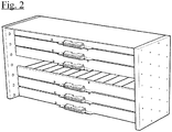
Figure 2 is likeFigure 1 , but seen from behind, although the general connection board between the elements has been omitted. -
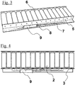
Figure 3 is a perspective view of an element according to the invention. -
Figure 4 is a top view of an element according to the invention. -
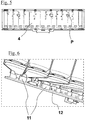
Figure 5 is analogous toFigure 4 , but in this case the arrangement of the control means, i.e. the processors, may be observed. -
Figure 6 is a detail perspective view of the connection between the elements and the general connection board. - As may be observed in the figures, the invention relates to a
battery element 1 comprising a plurality ofbattery cells 2 arranged in a line, which comprises power-conductingtracks 3 that connect thecells 2 in series and/or in parallel, measuring means for measuring the individual voltages of thecells 2, said measuring means comprising processors P, and voltagesensing tap tracks 4 between the terminals of eachcell 2. - These characteristics being already known, as may be seen, for example, in
Figure 3 , the element comprises a printedcircuit board 5 or a set ofprinted circuit boards cells 2, the power-conductingtracks 3, the voltagesensing tap tracks 4 and the processors P being integrated into the printed circuit boards, and the printed circuit board(s) 5, 6, 7 comprising, on one edge thereof, a generaloutput connection terminal 9 of the element, which supplies the aggregate voltage of thecells 2 of theelement 1 and the voltage state signals of each of thecells 2. - As may be seen in
Figure 5 , thecells 2 are cylindrical, with the terminals placed on opposite sides and adjacent cells placed in the reverse direction. - As may be observed in
Figure 3 , the element comprises three printedcircuit boards cells 2, and arranged facing said terminals, and the third, 7, arranged on one side of thecells 2 and mechanically and electrically connected to the other two, 5, 6. - In
Figure 5 , it may also be observed that the processors P are arranged on thethird board 7, on the side facing thecells 2 of theelement 1, and in the areas of thethird board 7 facing the free volume that is configured between thecells 2 and thethird board 7. For example, in this figure, wherein the cells have been made transparent, it may be observed that the processors are arranged at the level of contact site between adjacent cells, which is where there is space to house them. - As may be observed in this figure, it is not necessary for each cell to have a processor; instead, these functions can be grouped together, such that one chip controls a group of cells. In this latter case, a digital communication bus is envisaged to send the voltage and temperature signals to the corresponding processor.
- The power-conducting
tracks 3 are arranged on the twoboards third board 7. - The voltage
sensing tap tracks 4 are distributed between the twoboards third board 7. - The mechanical junction between the boards comprises openings on the
third board 7, and complementary flanges at the joint edge of the other twoboards - As may be observed in
Figure 5 , thegeneral connection terminal 9 is arranged on one edge of thethird board 7, preferably at the centre of the edge. - As may be observed in
Figures 1 ,2 and6 , the invention also relates to a battery comprising a plurality of elements according to the invention, which comprises acasing 10, provided with contiguous receptacles for each of the elements, each receptacle being equipped, at the bottom thereof, with aconnection terminal 11 for each of thegeneral connection terminals 9 of theelements 1. - Finally, as may be observed in
Figure 6 , aconnection board 12 is envisaged, which is provided with aconnection 11 for each of thebattery elements 1. - Although we have referred to a specific embodiment of the invention, it is evident, for persons skilled in the art, that the battery element described is susceptible to numerous variations and modifications, and that all the details mentioned above may be replaced with other technically equivalent ones, without going beyond the scope of protection defined by the attached claims.
Claims (12)
- Battery element (1) comprising a plurality of battery cells (2) arranged in a line, which comprises power-conducting tracks (3) that connect the cells (2) in series and/or in parallel, measuring means for measuring the individual voltages of the cells (2), said measuring means comprising processors (P) and voltage sensing tap tracks (4) between the terminals of each cell (2), characterised in that it comprises a printed circuit board (5) or a set of printed circuit boards (5, 6, 7) joined to one another and at least one of which is provided with openings (8) for the passage and connection of the terminals of the cells (2), the power-conducting tracks (3), the voltage sensing tap tracks (4) and the processors (P) being integrated into the printed circuit boards, the printed circuit board(s) (5, 6, 7), comprising, on one edge thereof, a general output connection terminal (9) of the element, which supplies the aggregate voltage of the cells (2) of the element (1) and the voltage state signals of each of the cells (2).
- Element according to claim 1, wherein the cells (2) are prismatic, with the terminals placed on the same side, comprising a single printed circuit board (5), and wherein the connections between the terminals and the tracks are made by welding.
- Element according to claim 1, wherein the cells (2) are cylindrical, with the terminals placed on opposite sides and adjacent cells placed in the reverse direction, comprising three printed circuit boards (5, 6, 7), two of which, (5, 6), are provided with openings for the passage and connection of the terminals of the cells (2), and are placed facing said terminals, and the third (7) is placed on one side of the cells (2), and is mechanically and electrically connected to the other two, (5, 6).
- Element according to claim 4, wherein:- the processors (P) are arranged on the third board (7), on the side facing the cells (2) of the element (1), and in the areas of the latter facing the free volume that is configured between the cells (2) and the third board (7);- the power-conducting tracks (3) are arranged on the two boards (5, 6) facing said terminals and on the third board (7);- the voltage sensing tap tracks (4) are distributed between the two boards (5, 6) facing said terminals and the third board (7).
- Element according to claim 4, wherein the mechanical junction between the boards comprises openings on the third board (7), and complementary flanges at the joint edge of the other two boards (5, 6).
- Element according to the preceding claim, wherein the connection of the voltage sensing tap tracks (4) at the level of the junction between the boards is made by welding.
- Element according to any of claims 3 to 6, wherein the terminals of the cells and the power-conducting tracks (3) are connected by means of screws.
- Element according to any of claims 3 to 7, wherein the general connection terminal (9) is arranged on one edge of the third board (7).
- Element according to claim 8, wherein the connection is placed at the centre of the edge.
- Element according to any of the preceding claims, comprising temperature sensors arranged jointly with the processors.
- Battery comprising a plurality of elements according to any of claims 1 to 10, comprising a casing (10) provided with contiguous receptacles for each of the elements, each receptacle being equipped, at the bottom thereof, with a connection terminal (11) for each of the general connection terminals (9) of the elements (1).
- Battery according to claim 11, comprising a connection board (12) equipped with a connection (11) for each of the battery elements (1).
Applications Claiming Priority (2)
| Application Number | Priority Date | Filing Date | Title |
|---|---|---|---|
| ES201430844A ES2555672B1 (en) | 2014-06-03 | 2014-06-03 | BATTERY ELEMENT THAT INCLUDES A PLURALITY OF BATTERY CELLS ARRANGED ONLINE |
| PCT/ES2015/070431 WO2015185776A1 (en) | 2014-06-03 | 2015-06-02 | Battery element comprising a plurality of battery cells disposed in a line |
Publications (2)
| Publication Number | Publication Date |
|---|---|
| EP3154109A1 true EP3154109A1 (en) | 2017-04-12 |
| EP3154109A4 EP3154109A4 (en) | 2017-07-19 |
Family
ID=54766199
Family Applications (1)
| Application Number | Title | Priority Date | Filing Date |
|---|---|---|---|
| EP15802465.3A Withdrawn EP3154109A4 (en) | 2014-06-03 | 2015-06-02 | Battery element comprising a plurality of battery cells disposed in a line |
Country Status (3)
| Country | Link |
|---|---|
| EP (1) | EP3154109A4 (en) |
| ES (1) | ES2555672B1 (en) |
| WO (1) | WO2015185776A1 (en) |
Cited By (1)
| Publication number | Priority date | Publication date | Assignee | Title |
|---|---|---|---|---|
| EP3588608A1 (en) * | 2018-06-28 | 2020-01-01 | KONE Corporation | Battery pack, frequency converter and transport system |
Family Cites Families (14)
| Publication number | Priority date | Publication date | Assignee | Title |
|---|---|---|---|---|
| GB2375223A (en) * | 2001-05-03 | 2002-11-06 | Provector Ltd | Battery management system. |
| JP3826895B2 (en) * | 2003-04-04 | 2006-09-27 | ソニー株式会社 | battery pack |
| JP4036805B2 (en) * | 2003-08-05 | 2008-01-23 | 三洋電機株式会社 | Pack battery |
| US8035986B2 (en) * | 2008-06-30 | 2011-10-11 | Lg Chem, Ltd. | Battery cell interconnect and voltage sensing assembly and method for coupling battery cell assemblies thereto |
| JPWO2011024477A1 (en) * | 2009-08-31 | 2013-01-24 | 三洋電機株式会社 | Battery module, battery system and electric vehicle |
| JP2012028186A (en) * | 2010-07-23 | 2012-02-09 | Sanyo Electric Co Ltd | Battery module, battery system, and electric vehicle |
| WO2011132434A1 (en) * | 2010-04-22 | 2011-10-27 | 三洋電機株式会社 | Battery module, electric vehicle provided with same, mobile body, power storage device, power source device, and electric equipment |
| US20130224532A1 (en) * | 2010-11-05 | 2013-08-29 | Alelion Batteries Ab | Battery assembly |
| JP6012595B2 (en) * | 2011-03-29 | 2016-10-25 | 三洋電機株式会社 | Battery module, battery system, electric vehicle, moving object, power storage device, power supply device, and electric device |
| JP5646046B2 (en) * | 2011-04-04 | 2014-12-24 | 日立オートモティブシステムズ株式会社 | Power storage module |
| FR2976761B1 (en) * | 2011-06-17 | 2014-05-02 | Commissariat Energie Atomique | PRINTED CIRCUIT FOR INTERCONNECTING AND MEASURING BATTERY BATTERY ACCUMULATORS |
| JP2013080693A (en) * | 2011-09-20 | 2013-05-02 | Auto Network Gijutsu Kenkyusho:Kk | Wiring module for battery |
| ES2444018B1 (en) * | 2013-06-18 | 2014-12-04 | Dachs Electrónica, S. A. | Battery comprising a plurality of rechargeable cells arranged in matrix |
| CN203553300U (en) * | 2013-11-18 | 2014-04-16 | 中航锂电(洛阳)有限公司 | Battery system and PCB (printed circuit board) wiring board assembly thereof |
-
2014
- 2014-06-03 ES ES201430844A patent/ES2555672B1/en not_active Expired - Fee Related
-
2015
- 2015-06-02 EP EP15802465.3A patent/EP3154109A4/en not_active Withdrawn
- 2015-06-02 WO PCT/ES2015/070431 patent/WO2015185776A1/en not_active Ceased
Cited By (3)
| Publication number | Priority date | Publication date | Assignee | Title |
|---|---|---|---|---|
| EP3588608A1 (en) * | 2018-06-28 | 2020-01-01 | KONE Corporation | Battery pack, frequency converter and transport system |
| CN110660952A (en) * | 2018-06-28 | 2020-01-07 | 通力股份公司 | Battery pack, frequency converter and transportation system |
| US11431051B2 (en) | 2018-06-28 | 2022-08-30 | Kone Corporation | Battery pack, frequency converter and transport system |
Also Published As
| Publication number | Publication date |
|---|---|
| WO2015185776A1 (en) | 2015-12-10 |
| ES2555672B1 (en) | 2016-11-03 |
| EP3154109A4 (en) | 2017-07-19 |
| ES2555672A2 (en) | 2016-01-07 |
| ES2555672R2 (en) | 2016-01-14 |
Similar Documents
| Publication | Publication Date | Title |
|---|---|---|
| US11539087B2 (en) | Vehicle energy-storage systems | |
| US7762832B2 (en) | Systems for providing electrical interconnection between solar modules | |
| CN101769952B (en) | Voltage detecting device of secondary battery module | |
| CN109690825B (en) | Connection module | |
| MX368236B (en) | Battery module with a temperature monitoring assembly. | |
| US11024890B2 (en) | Transmitting device for transmitting electrical signals from at least one galvanic cell to at least one electronic evaluating unit | |
| KR102711055B1 (en) | Battery module and battery pack including the same | |
| WO2017047258A1 (en) | Battery pack | |
| CN108735930B (en) | Power storage module unit and battery pack | |
| US20150224892A1 (en) | Integrated voltage sense and bus bar system and method for vehicles having a traction battery | |
| WO2019044747A1 (en) | Power storage system and container-type power storage system | |
| KR20150033023A (en) | Battery Pack | |
| WO2022258587A3 (en) | Modular battery system | |
| EP3633759A1 (en) | Storage battery unit | |
| US10084210B2 (en) | Electrochemical cell module | |
| US20170066343A1 (en) | Voltage monitoring system | |
| EP2612389B1 (en) | High-voltage battery with integrated cell connector | |
| EP3154109A1 (en) | Battery element comprising a plurality of battery cells disposed in a line | |
| WO2013104047A1 (en) | A system for power balance monitoring in batteries | |
| EP2966707A1 (en) | Battery module | |
| EP2892089B1 (en) | Electric wire routing structure for bus bar module | |
| EP3633760A1 (en) | Storage battery unit | |
| KR102331063B1 (en) | Battery module | |
| JP2014186001A (en) | Battery pack | |
| US20160351869A1 (en) | Power source device |
Legal Events
| Date | Code | Title | Description |
|---|---|---|---|
| STAA | Information on the status of an ep patent application or granted ep patent |
Free format text: STATUS: THE INTERNATIONAL PUBLICATION HAS BEEN MADE |
|
| PUAI | Public reference made under article 153(3) epc to a published international application that has entered the european phase |
Free format text: ORIGINAL CODE: 0009012 |
|
| STAA | Information on the status of an ep patent application or granted ep patent |
Free format text: STATUS: REQUEST FOR EXAMINATION WAS MADE |
|
| 17P | Request for examination filed |
Effective date: 20161229 |
|
| AK | Designated contracting states |
Kind code of ref document: A1 Designated state(s): AL AT BE BG CH CY CZ DE DK EE ES FI FR GB GR HR HU IE IS IT LI LT LU LV MC MK MT NL NO PL PT RO RS SE SI SK SM TR |
|
| AX | Request for extension of the european patent |
Extension state: BA ME |
|
| A4 | Supplementary search report drawn up and despatched |
Effective date: 20170616 |
|
| RIC1 | Information provided on ipc code assigned before grant |
Ipc: H01M 10/42 20060101ALI20170609BHEP Ipc: H01M 2/10 20060101ALI20170609BHEP Ipc: H01M 10/48 20060101ALI20170609BHEP Ipc: H01M 2/20 20060101AFI20170609BHEP |
|
| DAV | Request for validation of the european patent (deleted) | ||
| DAX | Request for extension of the european patent (deleted) | ||
| STAA | Information on the status of an ep patent application or granted ep patent |
Free format text: STATUS: EXAMINATION IS IN PROGRESS |
|
| 17Q | First examination report despatched |
Effective date: 20190123 |
|
| GRAP | Despatch of communication of intention to grant a patent |
Free format text: ORIGINAL CODE: EPIDOSNIGR1 |
|
| STAA | Information on the status of an ep patent application or granted ep patent |
Free format text: STATUS: GRANT OF PATENT IS INTENDED |
|
| INTG | Intention to grant announced |
Effective date: 20191016 |
|
| STAA | Information on the status of an ep patent application or granted ep patent |
Free format text: STATUS: THE APPLICATION IS DEEMED TO BE WITHDRAWN |
|
| 18D | Application deemed to be withdrawn |
Effective date: 20200227 |