EP3154104A1 - Batteriepack mit trennvorrichtung - Google Patents
Batteriepack mit trennvorrichtung Download PDFInfo
- Publication number
- EP3154104A1 EP3154104A1 EP15189064.7A EP15189064A EP3154104A1 EP 3154104 A1 EP3154104 A1 EP 3154104A1 EP 15189064 A EP15189064 A EP 15189064A EP 3154104 A1 EP3154104 A1 EP 3154104A1
- Authority
- EP
- European Patent Office
- Prior art keywords
- separating
- battery pack
- rail
- battery modules
- battery
- Prior art date
- Legal status (The legal status is an assumption and is not a legal conclusion. Google has not performed a legal analysis and makes no representation as to the accuracy of the status listed.)
- Granted
Links
Images


Classifications
-
- B—PERFORMING OPERATIONS; TRANSPORTING
- B60—VEHICLES IN GENERAL
- B60L—PROPULSION OF ELECTRICALLY-PROPELLED VEHICLES; SUPPLYING ELECTRIC POWER FOR AUXILIARY EQUIPMENT OF ELECTRICALLY-PROPELLED VEHICLES; ELECTRODYNAMIC BRAKE SYSTEMS FOR VEHICLES IN GENERAL; MAGNETIC SUSPENSION OR LEVITATION FOR VEHICLES; MONITORING OPERATING VARIABLES OF ELECTRICALLY-PROPELLED VEHICLES; ELECTRIC SAFETY DEVICES FOR ELECTRICALLY-PROPELLED VEHICLES
- B60L3/00—Electric devices on electrically-propelled vehicles for safety purposes; Monitoring operating variables, e.g. speed, deceleration or energy consumption
- B60L3/0007—Measures or means for preventing or attenuating collisions
-
- H—ELECTRICITY
- H01—ELECTRIC ELEMENTS
- H01M—PROCESSES OR MEANS, e.g. BATTERIES, FOR THE DIRECT CONVERSION OF CHEMICAL ENERGY INTO ELECTRICAL ENERGY
- H01M50/00—Constructional details or processes of manufacture of the non-active parts of electrochemical cells other than fuel cells, e.g. hybrid cells
- H01M50/20—Mountings; Secondary casings or frames; Racks, modules or packs; Suspension devices; Shock absorbers; Transport or carrying devices; Holders
- H01M50/262—Mountings; Secondary casings or frames; Racks, modules or packs; Suspension devices; Shock absorbers; Transport or carrying devices; Holders with fastening means, e.g. locks
-
- B—PERFORMING OPERATIONS; TRANSPORTING
- B60—VEHICLES IN GENERAL
- B60L—PROPULSION OF ELECTRICALLY-PROPELLED VEHICLES; SUPPLYING ELECTRIC POWER FOR AUXILIARY EQUIPMENT OF ELECTRICALLY-PROPELLED VEHICLES; ELECTRODYNAMIC BRAKE SYSTEMS FOR VEHICLES IN GENERAL; MAGNETIC SUSPENSION OR LEVITATION FOR VEHICLES; MONITORING OPERATING VARIABLES OF ELECTRICALLY-PROPELLED VEHICLES; ELECTRIC SAFETY DEVICES FOR ELECTRICALLY-PROPELLED VEHICLES
- B60L50/00—Electric propulsion with power supplied within the vehicle
- B60L50/50—Electric propulsion with power supplied within the vehicle using propulsion power supplied by batteries or fuel cells
- B60L50/60—Electric propulsion with power supplied within the vehicle using propulsion power supplied by batteries or fuel cells using power supplied by batteries
- B60L50/64—Constructional details of batteries specially adapted for electric vehicles
-
- H—ELECTRICITY
- H01—ELECTRIC ELEMENTS
- H01M—PROCESSES OR MEANS, e.g. BATTERIES, FOR THE DIRECT CONVERSION OF CHEMICAL ENERGY INTO ELECTRICAL ENERGY
- H01M50/00—Constructional details or processes of manufacture of the non-active parts of electrochemical cells other than fuel cells, e.g. hybrid cells
- H01M50/20—Mountings; Secondary casings or frames; Racks, modules or packs; Suspension devices; Shock absorbers; Transport or carrying devices; Holders
- H01M50/204—Racks, modules or packs for multiple batteries or multiple cells
-
- H—ELECTRICITY
- H01—ELECTRIC ELEMENTS
- H01M—PROCESSES OR MEANS, e.g. BATTERIES, FOR THE DIRECT CONVERSION OF CHEMICAL ENERGY INTO ELECTRICAL ENERGY
- H01M50/00—Constructional details or processes of manufacture of the non-active parts of electrochemical cells other than fuel cells, e.g. hybrid cells
- H01M50/20—Mountings; Secondary casings or frames; Racks, modules or packs; Suspension devices; Shock absorbers; Transport or carrying devices; Holders
- H01M50/262—Mountings; Secondary casings or frames; Racks, modules or packs; Suspension devices; Shock absorbers; Transport or carrying devices; Holders with fastening means, e.g. locks
- H01M50/264—Mountings; Secondary casings or frames; Racks, modules or packs; Suspension devices; Shock absorbers; Transport or carrying devices; Holders with fastening means, e.g. locks for cells or batteries, e.g. straps, tie rods or peripheral frames
-
- H—ELECTRICITY
- H01—ELECTRIC ELEMENTS
- H01M—PROCESSES OR MEANS, e.g. BATTERIES, FOR THE DIRECT CONVERSION OF CHEMICAL ENERGY INTO ELECTRICAL ENERGY
- H01M50/00—Constructional details or processes of manufacture of the non-active parts of electrochemical cells other than fuel cells, e.g. hybrid cells
- H01M50/50—Current conducting connections for cells or batteries
- H01M50/502—Interconnectors for connecting terminals of adjacent batteries; Interconnectors for connecting cells outside a battery casing
- H01M50/503—Interconnectors for connecting terminals of adjacent batteries; Interconnectors for connecting cells outside a battery casing characterised by the shape of the interconnectors
-
- H—ELECTRICITY
- H01—ELECTRIC ELEMENTS
- H01M—PROCESSES OR MEANS, e.g. BATTERIES, FOR THE DIRECT CONVERSION OF CHEMICAL ENERGY INTO ELECTRICAL ENERGY
- H01M50/00—Constructional details or processes of manufacture of the non-active parts of electrochemical cells other than fuel cells, e.g. hybrid cells
- H01M50/50—Current conducting connections for cells or batteries
- H01M50/502—Interconnectors for connecting terminals of adjacent batteries; Interconnectors for connecting cells outside a battery casing
- H01M50/509—Interconnectors for connecting terminals of adjacent batteries; Interconnectors for connecting cells outside a battery casing characterised by the type of connection, e.g. mixed connections
- H01M50/51—Connection only in series
-
- H—ELECTRICITY
- H01—ELECTRIC ELEMENTS
- H01M—PROCESSES OR MEANS, e.g. BATTERIES, FOR THE DIRECT CONVERSION OF CHEMICAL ENERGY INTO ELECTRICAL ENERGY
- H01M50/00—Constructional details or processes of manufacture of the non-active parts of electrochemical cells other than fuel cells, e.g. hybrid cells
- H01M50/50—Current conducting connections for cells or batteries
- H01M50/572—Means for preventing undesired use or discharge
- H01M50/574—Devices or arrangements for the interruption of current
- H01M50/579—Devices or arrangements for the interruption of current in response to shock
-
- H—ELECTRICITY
- H01—ELECTRIC ELEMENTS
- H01M—PROCESSES OR MEANS, e.g. BATTERIES, FOR THE DIRECT CONVERSION OF CHEMICAL ENERGY INTO ELECTRICAL ENERGY
- H01M2200/00—Safety devices for primary or secondary batteries
-
- H—ELECTRICITY
- H01—ELECTRIC ELEMENTS
- H01M—PROCESSES OR MEANS, e.g. BATTERIES, FOR THE DIRECT CONVERSION OF CHEMICAL ENERGY INTO ELECTRICAL ENERGY
- H01M2220/00—Batteries for particular applications
- H01M2220/20—Batteries in motive systems, e.g. vehicle, ship, plane
-
- Y—GENERAL TAGGING OF NEW TECHNOLOGICAL DEVELOPMENTS; GENERAL TAGGING OF CROSS-SECTIONAL TECHNOLOGIES SPANNING OVER SEVERAL SECTIONS OF THE IPC; TECHNICAL SUBJECTS COVERED BY FORMER USPC CROSS-REFERENCE ART COLLECTIONS [XRACs] AND DIGESTS
- Y02—TECHNOLOGIES OR APPLICATIONS FOR MITIGATION OR ADAPTATION AGAINST CLIMATE CHANGE
- Y02E—REDUCTION OF GREENHOUSE GAS [GHG] EMISSIONS, RELATED TO ENERGY GENERATION, TRANSMISSION OR DISTRIBUTION
- Y02E60/00—Enabling technologies; Technologies with a potential or indirect contribution to GHG emissions mitigation
- Y02E60/10—Energy storage using batteries
-
- Y—GENERAL TAGGING OF NEW TECHNOLOGICAL DEVELOPMENTS; GENERAL TAGGING OF CROSS-SECTIONAL TECHNOLOGIES SPANNING OVER SEVERAL SECTIONS OF THE IPC; TECHNICAL SUBJECTS COVERED BY FORMER USPC CROSS-REFERENCE ART COLLECTIONS [XRACs] AND DIGESTS
- Y02—TECHNOLOGIES OR APPLICATIONS FOR MITIGATION OR ADAPTATION AGAINST CLIMATE CHANGE
- Y02T—CLIMATE CHANGE MITIGATION TECHNOLOGIES RELATED TO TRANSPORTATION
- Y02T10/00—Road transport of goods or passengers
- Y02T10/60—Other road transportation technologies with climate change mitigation effect
- Y02T10/70—Energy storage systems for electromobility, e.g. batteries
Definitions
- the invention relates to a battery pack with a disconnecting device for separating a plurality of battery modules connected in series in the battery module, wherein the battery modules are electrically connected to each other via releasably plugged module connector, and a vehicle with an electric drive and such a battery pack.
- HV traction batteries for electric vehicles usually have such a structure.
- HV traction batteries in electric vehicles in the event of a crash to electrical hazard of e.g. Rescue personnel lead, if the housing is damaged and thus a contact protection is no longer given.
- the DE 10 2010 037 206 A1 describes an electrical energy store having a safety function for reducing output voltage values, the energy store having series-connected voltage-supplying modules and electrical connections through which the modules are connected. It is also described a mechanical separating device which is movable from a rest position to an operative position, wherein the electrical connections are severed by a V flesh into the operative position. In each case, a separating device is provided for each connection between two modules.
- a battery pack is provided with a separating device for separating a plurality of battery modules connected in series in the battery pack, wherein the battery modules are electrically connected to one another via detachably plugged module connectors and wherein the separating device has a separating rail displaceable in its longitudinal direction, the separating device is arranged laterally along the battery modules, a plurality Module connectors are mechanically connected to the separation rail of the separation device and the electrical connections are separable by a movement of the separation rail in the longitudinal direction.
- a releasably plugged module connector to understand a module connector, which is designed as an electrical conductor for the electrical connection of two battery modules, and which has on two sides or ends a part of the plug and socket principle corresponding plug connection, and which under application of a vorgebaren force with a respective corresponding part of the connector having connection of the battery module is electrically connectable or solvable by applying a vorgebaren force of this.
- Such a battery pack has the advantage that the electrical separation of the individual battery modules passive and purely mechanical, for example triggered by a deformation of the housing takes place.
- all electrical connections between the battery modules can be separated by a single separator.
- the separating device is advantageously designed such that the separating rail can be fixed relative to the battery modules and by the action of a force which exceeds a predetermined height in a predeterminable direction, relative to the battery modules in its longitudinal direction is displaceable.
- the battery pack is designed such that the separation device for the separation rail has a guide which is firmly connected to the battery modules.
- the fixation of the separating rail relative to the battery modules is advantageously carried out by means of a screw or a bolt.
- An example arranged transversely to the longitudinal direction of the separating rail bolt allows their movement only after the action of a force which exceeds the permissible shear force of the bolt, so that a threshold value can be predetermined by the choice of the strength and the material of the bolt.
- the separating device on a stamp which is suitable to receive a planar force or force component in the longitudinal direction of the separating rail and to transfer this to the separating rail.
- battery packs are arranged in an installation space, such as inside a vehicle.
- the separation rail is moved over a stamp resting on the inner wall of the installation space and the electrical connections between the battery modules are separated.
- the separating rail is designed as a U-profile or HPprofile.
- Such profiles have a high rigidity and are therefore well suited for the transmission of force to a sheared bolt and for the transmission of power to solve a plurality of possibly solidly executed connectors.
- the battery pack is designed such that the connections between all battery modules are electrically separable by a separator.
- Such an embodiment reduces the complexity of the mechanical structure and at the same time ensures that after a corresponding deformation of the battery pack not only a part of the connections are interrupted.
- the maximum occurring in the battery pack voltage can thus be limited to the voltage of a battery module. This is usually less than 60 volts DC, which means that it is safe to touch.
- the battery pack is advantageously designed such that all module connectors are guided over a central axis, along which the separating device is arranged. Such an embodiment of the battery pack allows the separation of all battery modules with a single separator.
- the battery modules are arranged in a mounting frame, wherein a part of the mounting frame at the same time forms a guide for the separation rail.
- the same mounting frame or the same part of a mounting frame assume a dual function, in which he as a holding or support frame for the mechanical recording of a battery module and on the other hand as a guide for the movement of the separating rail is executed.
- the separation rail advantageously has recesses, are passed through the module connector.
- the battery pack is designed such that module connectors are secured against slipping out of the recesses during a movement of the separating rail.
- the separating rail is advantageously mounted displaceably within a hollow profile.
- the hollow profile may for example be a part or a portion of the mounting frame.
- the hollow profile is advantageously designed as a rectangular profile.
- the terminals of the battery modules are designed as laterally arranged plug-in connections, wherein the module connectors are inserted in the lateral direction in this.
- Such an embodiment has the advantage that the battery modules are structurally easy to connect to one another and with a laterally arranged separating device.
- the connection of the battery modules with each other and / or their connection with the separator for example, as a flat plate executable.
- Also provided according to the invention is a vehicle with an electric drive and a battery pack according to one of the previously described embodiments.
- an installation space is typically slightly larger than the battery pack. If this is deformed by an accident, leads a battery pack with a separator of the type described above to an electrical separation of the battery pack into individual battery modules whose individual voltage is below a permissible contact voltage.
- the vehicle is advantageously designed such that the separating rail is aligned in the direction of a Hauptcrashraum.
- the separating rail is advantageously aligned parallel to the longitudinal axis of the vehicle.
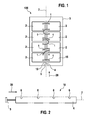
- Fig. 1 shows a battery pack 100 which is arranged in an installation space 3. It is off Fig. 1 a separation device 10 for the separation of a plurality of series-connected battery modules 2 can be seen, in which the battery modules 2 are electrically connected to each other via releasably plugged module connector 1.
- the separating device 10 has a separating rail 4 which is displaceable in its longitudinal direction 20 and which is arranged centrally on a central axis 7 between the battery modules 2.
- the separating device 10 is arranged laterally along the battery modules 2 and mechanically connected to a plurality of module connectors 1 crossing them.
- the electrical connections made by the detachably plugged module connectors 1 are separable by a movement of the separating rail 4 in its longitudinal direction 20.
- the battery pack 100 includes a battery control unit BCU 15.
- the separation rail 4 In a deformation of the installation space 3 in the direction of the longitudinal direction 20 of the separation rail 4, the separation rail 4 is moved over a voltage applied to the inner wall of the installation space 3 punch 5 and the electrical connections between the battery modules 2 are separated. All module connectors 1 are guided over the central axis 7.
- the battery pack 100 with a plurality of battery modules 2 is separated by a single separator 10 electrically into individual battery modules 2.
- Fig. 2 shows a separating device 10, which has a separating rail 4 with recesses 6 and a punch 5.
- the recesses 6 are adapted to receive module connector 1 and to move in the direction of the longitudinal direction 20 of the separator rail 4.
- the punch 5 is suitable for receiving a force in the longitudinal direction 20 and transferring it to the separating rail 4.
- Fig. 3 5 shows a simplified illustration of a battery pack 100 with battery modules 2 arranged in a mounting frame 8 ', 8 ".
- the mounting frame 8', 8" has longitudinal profiles 8 'and transverse profiles 8 ", which are designed as hollow profiles.
- the mounting rail 4 is within the hollow profile or within the longitudinal profile 8 'in its longitudinal direction 20th
- the battery pack 100 has a plurality of separating devices 10, the separating rails 4 of which are displaceably arranged in a plurality of longitudinal profiles 8 'of the mounting frame 8', 8 ".
- Each separating rail 4 has a punch 5 for surface force absorption.
- the battery pack 100 has a battery control unit BCU 15 whose connections are designed in the same way as those of the battery modules 2 as laterally arranged module terminals 14 and in the module connector 1 in the lateral direction can be inserted.
- Fig. 4 1 shows a longitudinal section 8 'of the mounting frame 8', 8 "arranged in a lateral section
- the longitudinal profile 8 ' is designed as a hollow profile, concretely as a rectangular profile
- the battery module 2 is an angle section 17 with the longitudinal profile 8' of the mounting frame ', 8 "firmly connected, with fasteners such as screws are not visible in this view.
- the battery module 2 has a plurality of battery cells 16 which are interconnected with cell connectors 11.
- the connection of the battery module 2 is designed as laterally arranged module connection 14.
- a module connector 1 is inserted laterally.
- the module connector 1 is connected via a rigid connection 12 with the separator rail 4.
- the rigid connection 12 leads via a hole 9 designed as an opening in the rectangular profile of the longitudinal profile 8 '.
- H-profile separator rail 4 is slidably mounted in the longitudinal direction 20.
- a bolt or a screw can be positioned, by means of which a fixing of the separating rail 4 relative to the battery module 2 can take place. Only after the action of a force which exceeds the permissible shear force of the bolt or screw, the separating rail 4 relative to the battery module 2 is displaceable.
Landscapes
- Chemical & Material Sciences (AREA)
- Chemical Kinetics & Catalysis (AREA)
- Electrochemistry (AREA)
- General Chemical & Material Sciences (AREA)
- Engineering & Computer Science (AREA)
- Life Sciences & Earth Sciences (AREA)
- Sustainable Development (AREA)
- Sustainable Energy (AREA)
- Power Engineering (AREA)
- Transportation (AREA)
- Mechanical Engineering (AREA)
- Battery Mounting, Suspending (AREA)
Abstract
Description
- Die Erfindung betrifft einen Batteriepack mit Trennvorrichtung zur Trennung mehrerer im Batteriepack in Reihe geschalteter Batteriemodule, wobei die Batteriemodule über lösbar gesteckte Modulverbinder elektrisch miteinander verbunden sind, sowie ein Fahrzeug mit einem elektrischen Antrieb und einem derartigen Batteriepack.
- Für viele Anwendungen werden elektrochemische Zellen zu Batteriemodulen und diese wiederum zu Batteriepacks in Reihe geschaltet. Auf diese Weise können Hochspannungsbatterien mit einer Ausgangsspannung von mehreren hundert Volt aufgebaut werden. In der Automobilindustrie eingesetzte HV-Traktionsbatterien für Fahrzeuge mit Elektroantrieb weisen in der Regel einen derartigen Aufbau auf.
- Üblicherweise sind die hochspannungsbehafteten Komponenten eines Batteriepacks gegen Berührung geschützt. Im Falle einer mechanischen Beschädigung des Batteriepacks jedoch ist ein solcher Berührungsschutz möglicherweise nicht mehr gegeben, wobei selbst ein teilweise zerstörter Batteriepack noch Spannungen im Hochspanungsbereich aufweisen kann.
- So können HV-Traktionsbatterien in Elektrofahrzeugen im Crashfall zu elektrischer Gefährdung von z.B. Rettungspersonal führen, falls das Gehäuse beschädigt wird und damit ein Berührungsschutz nicht mehr gegeben ist.
- Zum Herabsetzen der Batteriespannung bei beispielsweise einer Beschädigung des Batteriegehäuses sind aus dem Stand der Technik ein Energiespeicher mit einer Sicherheitsfunktion und ein Verfahren zum Herabsetzen der elektrischen Ausgangsspannung eines elektrischen Energiespeichers bekannt.
- Die
DE 10 2010 037 206 A1 beschreibt einen elektrischen Energiespeicher mit einer Sicherheitsfunktion zum Herabsetzen von Ausgangsspannungswerten, wobei der Energiespeicher in Serie geschaltete spannungsliefernde Module und elektrische Verbindungen aufweist, durch welche die Module verbunden sind. Es ist ferner eine mechanische Trenneinrichtung beschrieben, welche von einer Ruheposition in eine Wirkposition verfahrbar ist, wobei die elektrischen Verbindungen durch eine Verfahrung in die Wirkposition durchtrennbar sind. Dabei ist für jede Verbindung zwischen zwei Modulen jeweils eine Trenneinrichtung vorgesehen. - Erfindungsgemäß vorgesehen ist ein Batteriepack mit Trennvorrichtung zur Trennung mehrerer im Batteriepack in Reihe geschalteter Batteriemodule, wobei die Batteriemodule über lösbar gesteckte Modulverbinder elektrisch miteinander verbunden sind und wobei die Trennvorrichtung eine in ihrer Längsrichtung verschiebbare Trennschiene aufweist, die Trennvorrichtung seitlich entlang der Batteriemodule angeordnet ist, mehrere Modulverbinder mit der Trennschiene der Trennvorrichtung mechanisch verbunden sind und die elektrischen Verbindungen durch eine Bewegung der Trennschiene in deren Längsrichtung trennbar sind.
- Dabei ist unter einem lösbar gestecktem Modulverbinder ein Modulverbinder zu verstehen, der als elektrischer Leiter zur elektrischen Verbindung von zwei Batteriemodulen ausgeführt ist, und der an zwei Seiten oder Enden einen Teil einer dem Prinzip aus Stecker und Buchse entsprechenden Steckverbindung aufweist, und welcher unter Aufbringung einer vorgebaren Kraft mit einem den jeweils korrespondierendem Teil der Steckverbindung aufweisenden Anschluss des Batteriemoduls elektrisch verbindbar bzw. unter Aufbringung einer vorgebaren Kraft von diesem lösbar ist.
- Ein derartiger Batteriepack weist den Vorteil auf, dass die elektrische Trennung der einzelnen Batteriemodule passiv und rein mechanisch, beispielsweise ausgelöst durch eine Verformung des Gehäuses erfolgt. Dabei können mehrere, je nach Ausführungsform auch alle elektrischen Verbindungen zwischen den Batteriemodulen durch eine einzige Trennvorrichtung getrennt werden. Durch die Trennung der Batteriemodule wird nicht nur die maximal auftretende Spannung reduziert, sondern auch die Wahrscheinlichkeit von Kurzschlüssen und den damit verbundenen Gefährdungen reduziert. So führt beispielsweise eine unfallbedingte leitende Verbindung zwischen Batteriezellen benachbarter Batteriemodule nicht zwingend zu einem Kurzschluss. Eine elektronische Unterstützung, die im Crashfall unter Umständen nicht verfügbar ist oder fehlerhaft ausgelöst werden kann, ist nicht erforderlich.
- Dabei ist die Trennvorrichtung vorteilhaft derart ausgeführt, dass die Trennschiene gegenüber den Batteriemodulen fixierbar ist und durch Einwirkung einer Kraft, welche eine vorgebbare Höhe in einer vorgebbaren Richtung überschreitet, gegenüber den Batteriemodulen in ihrer Längsrichtung verschiebbar ist.
- Eine derartige Fixierung verhindert eine ungewollte Trennung der Batteriemodule, welche unweigerlich zu einem Ausfall des Batteriepacks führen würde. In Analogie zu einem Auslösemechanismus eines Airbags ist die Einwirkung einer Kraft oberhalb eines vorgebbaren Schwellwertes erforderlich, um eine Trennung der Batteriemodule zu bewirken.
- Vorteilhaft ist der Batteriepack derart ausgeführt, dass die Trennvorrichtung für die Trennschiene eine Führung aufweist, die fest mit den Batteriemodulen verbunden ist. Vorteilhaft ist in diesem Fall die Fixierung der Trennschiene als eine Fixierung der Trennschiene in der Führung ausgeführt.
- Vorteilhaft ist weiterhin die Fixierung der Trennschiene gegenüber den Batteriemodulen mittels einer Schraube oder eines Bolzens ausgeführt. Ein beispielsweise quer zur Längsrichtung der Trennschiene angeordneter Bolzen ermöglicht deren Bewegung erst nach Einwirkung einer Kraft, welche die zulässige Scherkraft des Bolzens übersteigt, sodass durch die Wahl der Stärke sowie des Materials des Bolzens ein Schwellwert vorgebbar ist.
- Vorteilhaft weist die Trennvorrichtung einen Stempel auf, der geeignet ist, flächig eine Kraft oder Kraftkomponente in der Längsrichtung der Trennschiene aufzunehmen und diese auf die Trennschiene zu übertragen. Häufig sind Batteriepacks in einem Einbauraum angeordnet, wie beispielsweise im Inneren eines Fahrzeugs. Bei einer Verformung des Einbauraums in Richtung der Längsrichtung der Trennschiene wird die Trennschiene über einen an der Innenwand des Einbauraumes anliegenden Stempel bewegt und die elektrischen Verbindungen zwischen den Batteriemodulen werden getrennt.
- Weiterhin vorteilhaft ist die Trennschiene als ein U-Profil oder HProfil ausgeführt. Derartige Profile weisen eine hohe Steifigkeit auf und sind daher gut für die Übertragung von Kraft auf einen abzuscherenden Bolzen sowie für die Übertragung von Kraft zur Lösung einer Mehrzahl von gegebenenfalls massiv ausgeführten Steckverbindern geeignet.
- Vorteilhaft ist der Batteriepack derart ausgeführt, dass durch eine Trennvorrichtung die Verbindungen zwischen allen Batteriemodulen elektrisch trennbar sind. Eine derartige Ausführung reduziert die Komplexität des mechanischen Aufbaus und stellt zugleich sicher, dass nach einer entsprechenden Verformung des Batteriepacks nicht nur ein Teil der Verbindungen unterbrochen sind. Die maximal im Batteriepack auftretende Spannung kann somit auf die Spannung eines Batteriemoduls beschränkt werden. Diese beträgt üblicherweise weniger als 60 Volt Gleichspannung, womit sie hinsichtlich einer Berührung als ungefährlich gilt.
- Ferner ist der Batteriepack vorteilhaft derart ausgeführt, dass alle Modulverbinder über eine zentrale Achse geführt werden, entlang derer die Trennvorrichtung angeordnet ist. Eine derartige Ausführung des Batteriepacks ermöglicht die Trennung aller Batteriemodule mit einer einzigen Trennvorrichtung.
- Vorteilhaft sind die Batteriemodule in einem Montagerahmen angeordnet, wobei ein Teil des Montagerahmens zugleich eine Führung für die Trennschiene ausbildet. Auf diese Weise kann derselbe Montagerahmen bzw. derselbe Teil eines Montagerahmens eine Doppelfunktion einnehmen, in dem er zum einen als Halte- oder Tragerahmen für die mechanische Aufnahme eines Batteriemoduls und zum anderen als eine Führung für die Bewegung der Trennschiene ausgeführt ist.
- In einer Ausführungsform weist die Trennschiene vorteilhaft Ausnehmungen auf, durch die Modulverbinder hindurchgeführt sind. Dabei ist das Batteriepack derart ausgeführt, dass Modulverbinder bei einer Bewegung der Trennschiene gegen ein Herausrutschen aus den Ausnehmungen gesichert sind.
- In einer anderen Ausführungsform ist die Trennschiene vorteilhaft innerhalb eines Hohlprofiles verschiebbar gelagert. Dabei kann das Hohlprofil beispielsweise ein Teil oder ein Abschnitt des Montagerahmens sein. Das Hohlprofil ist dabei vorteilhaft als Rechteckprofil ausgebildet. Weiterhin vorteilhaft weist das Hohlprofil oder der Montagerahmen Langlöcher auf, durch welche die Trennschiene mit den Modulverbindern verbunden ist. Die Verbindung kann beispielsweise durch eine Stange, eine Platte oder eine Konstruktion aus Profilen ausgeführt sein. Dabei erlauben die Langlöcher, dass die Trennschiene trotz ihrer mechanischen Verbindung mit den Modulverbindern innerhalb des Hohlprofiles verschiebbar ist.
- Weiterhin vorteilhaft sind die Anschlüsse der Batteriemodule als seitlich angeordnete Steckverbindungen ausgeführt, wobei die Modulverbinder in seitlicher Richtung in diese einsteckbar sind. Eine derartige Ausführung bietet den Vorteil, dass die Batteriemodule konstruktiv einfach untereinander sowie mit einer seitlich angeordneten Trennvorrichtung verbindbar sind. So ist die Verbindung der Batteriemodule untereinander und/oder deren Verbindung mit der Trennvorrichtung beispielsweise als ebene Platte ausführbar.
- Erfindungsgemäß vorgesehen ist ferner ein Fahrzeug mit einem elektrischen Antrieb und einem Batteriepack nach einer der vorbeschrieben Ausführungsformen. In einem Fahrzeug ist ein Einbauraum typischerweise geringfügig größer als der Batteriepack. Falls dieser durch einen Unfall deformiert wird, führt ein Batteriepack mit einer Trennvorrichtung der zuvor beschrieben Art zu einer elektrischen Trennung des Batteriepacks in einzelne Batteriemodule, deren Einzelspannung unterhalb einer zulässigen Berührungsspannung liegt.
- Dabei ist das Fahrzeug vorteilhaft derart ausgeführt, dass die Trennschiene in Richtung einer Hauptcrashrichtung ausgerichtet ist. Insbesondere ist die Trennschiene vorteilhaft parallel zur Längsachse des Fahrzeugs ausgerichtet. Nachfolgend wird die Erfindung unter Bezugnahme auf die anliegenden Zeichnungen anhand bevorzugter Ausführungsformen näher erläutert.
- Es zeigen:
- Fig. 1
- eine erste Ausführungsform eines erfindungsgemäßen Batteriepacks mit Trennvorrichtung;
- Fig. 2
- eine erste Ausführungsform der Trennvorrichtung aus
Fig. 1 ; - Fig. 3
- eine zweite Ausführungsform eines erfindungsgemäßen Batteriepacks mit Trennvorrichtung;
- Fig. 4
- eine Detailansicht der zweiten Ausführungsform mit einer Darstellung der Verbindung zwischen Trennschiene und Modulverbinder.
-
Fig. 1 zeigt einen Batteriepack 100, der in einem Einbauraum 3 angeordnet ist. Dabei ist ausFig. 1 eine Trennvorrichtung 10 zur Trennung mehrerer in Reihe geschalteter Batteriemodule 2 ersichtlich, bei der die Batteriemodule 2 über lösbar gesteckte Modulverbinder 1 elektrisch miteinander verbunden sind. Die Trennvorrichtung 10 weist eine in ihrer Längsrichtung 20 verschiebbare Trennschiene 4 auf, welche auf einer zentralen Achse 7 mittig zwischen den Batteriemodulen 2 angeordnet ist. Die Trennvorrichtung 10 ist seitlich entlang der Batteriemodule 2 angeordnet und mit mehreren, sie querenden Modulverbindern 1 mechanisch verbunden. Die durch die lösbar gesteckten Modulverbinder 1 ausgeführten elektrischen Verbindungen sind durch eine Bewegung der Trennschiene 4 in ihrer Längsrichtung 20 trennbar. Neben den Batteriemodulen 2 enthält der Batteriepack 100 eine Batteriekontrolleinheit BCU 15. Bei einer Verformung des Einbauraums 3 in Richtung der Längsrichtung 20 der Trennschiene 4 wird die Trennschiene 4 über einen an der Innenwand des Einbauraumes 3 anliegenden Stempel 5 bewegt und die elektrischen Verbindungen zwischen den Batteriemodulen 2 werden getrennt. Alle Modulverbinder 1 sind über die zentrale Achse 7 geführt. Der Batteriepack 100 mit einer Vielzahl von Batteriemodulen 2 ist durch eine einzige Trennvorrichtung 10 elektrisch in einzelne Batteriemodule 2 trennbar. -
Fig. 2 zeigt eine Trennvorrichtung 10, welche eine Trennschiene 4 mit Ausnehmungen 6 und einen Stempel 5 aufweist. Die Ausnehmungen 6 sind geeignet, Modulverbinder 1 aufzunehmen und in Richtung der Längsrichtung 20 der Trennschiene 4 zu bewegen. Der Stempel 5 ist geeignet, flächig eine Kraft in der Längsrichtung 20 aufzunehmen und diese auf die Trennschiene 4 zu übertragen. -
Fig. 3 zeigt eine vereinfachte Darstellung eines Batteriepacks 100 mit Batteriemodulen 2, die in einem Montagerahmen 8', 8" angeordnet sind. Der Montagerahmen 8', 8" weist Längsprofile 8' sowie Querprofile 8" auf, welche als Hohlprofile ausgeführt sind. Ein Teil 8' des Montagerahmens 8', 8", der hier einem Längsprofile 8' des Montagerahmens 8',8" entspricht, ist zugleich eine Führung für die Trennschiene 4. Die Trennschiene 4 ist innerhalb des Hohlprofils bzw. innerhalb des Längsprofils 8' in ihrer Längsrichtung 20 verschiebbar gelagert. Um alle Batteriemodule 2 voneinander trennen zu können, weist der Batteriepack 100 mehrere Trennvorrichtungen 10 auf, deren Trennschienen 4 in mehreren Längsprofilen 8' des Montagerahmens 8', 8" verschiebbar angeordnet sind. Dabei weist jede Trennschiene 4 einen Stempel 5 zur flächigen Kraftaufnahme auf. - Neben den Batteriemodulen 2 weist der Batteriepack 100 eine Batteriekontrolleinheit BCU 15 auf, deren Anschlüsse in gleicher Weise wie diejenigen der Batteriemodule 2 als seitlich angeordnete Modulanschlüsse 14 ausgeführt sind und in die Modulverbinder 1 in seitlicher Richtung einsteckbar sind. Eine diesbezügliche Detailansicht, Schnitt A-A', zeigt
Figur 4 . -
Fig. 4 zeigt ein in einem Längsprofil 8'des Montagerahmens 8', 8" angeordnetes Batteriemodul 2 im seitlichen Schnitt. Das Längsprofil 8' ist als Hohlprofil, konkret als Rechteckprofil ausgeführt. Das Batteriemodul 2 ist über ein Winkelprofil 17 mit dem Längsprofil 8' des Montagerahmens 8', 8" fest verbunden, wobei Befestigungsmittel wie Schrauben in dieser Ansicht nicht sichtbar sind. Das Batteriemodul 2 weist eine Mehrzahl von Batteriezellen 16 auf, die untereinander mit Zellverbindern 11 verbunden sind. Der Anschluss des Batteriemodules 2 ist als seitlich angeordneter Modulanschluss 14 ausgeführt. In diesen ist ein Modulverbinder 1 seitlich einsteckbar. Der Modulverbinder 1 ist über eine starre Verbindung 12 mit der Trennschiene 4 verbunden. Die starre Verbindung 12 führt über eine als Langloch 9 ausgeführte Öffnung in das Rechteckprofil des Längsprofils 8'. In diesem ist die als H-Profil ausgeführte Trennschiene 4 in Längsrichtung 20 verschiebbar gelagert. Entlang einer Bolzenposition 13 kann ein Bolzen oder eine Schraube positioniert sein, mittels derer eine Fixierung der Trennschiene 4 gegenüber dem Batteriemodul 2 erfolgen kann. Erst nach Einwirkung einer Kraft, welche die zulässige Scherkraft des Bolzens oder der Schraube übersteigt, ist die Trennschiene 4 gegenüber dem Batteriemodul 2 verschiebbar.
Claims (10)
- Batteriepack (100) mit Trennvorrichtung (10) zur Trennung mehrerer im Batteriepack (100) in Reihe geschalteter Batteriemodule (2), wobei die Batteriemodule (2) über lösbar gesteckte Modulverbinder (1) elektrisch miteinander verbunden sind,
dadurch gekennzeichnet, dass die Trennvorrichtung (10) eine in ihrer Längsrichtung (20) verschiebbare Trennschiene (4) aufweist, die Trennvorrichtung (10) seitlich entlang der Batteriemodule (2) angeordnet ist, mehrere Modulverbinder (1) mit der Trennschiene (4) der Trennvorrichtung (10) mechanisch verbunden sind und die elektrischen Verbindungen durch eine Bewegung der Trennschiene (4) in deren Längsrichtung (20) trennbar sind. - Batteriepack (100) mit Trennvorrichtung (10) nach Anspruch 1, dadurch gekennzeichnet, dass die Trennschiene (4) gegenüber den Batteriemodulen (2) fixierbar ist und durch Einwirkung einer Kraft, welche eine vorgebbare Höhe in einer vorgebbaren Richtung überschreitet, gegenüber den Batteriemodulen (2) in ihrer Längsrichtung (20) verschiebbar ist.
- Batteriepack (100) mit Trennvorrichtung (10) nach Anspruch 2, dadurch gekennzeichnet, dass die Fixierung der Trennschiene (4) gegenüber den Batteriemodulen (2) mittels einer Schraube oder eines Bolzens ausgeführt ist.
- Batteriepack (100) mit Trennvorrichtung (10) nach einem der vorherigen Ansprüche, dadurch gekennzeichnet, dass die Trennschiene (4) als ein U-Profil oder HProfil ausgeführt ist.
- Batteriepack (100) nach einem der vorherigen Ansprüche dadurch gekennzeichnet, dass durch eine Trennvorrichtung (10) alle Batteriemodule (2) elektrisch in einzelne Batteriemodule (2) trennbar sind.
- Batteriepack (100) nach einem der vorherigen Ansprüche, dadurch gekennzeichnet, dass alle Modulverbinder (1) über eine zentrale Achse (7) geführt werden, entlang derer die Trennvorrichtung (10) angeordnet ist.
- Batteriepack (100) nach einem der vorherigen Ansprüche, dadurch gekennzeichnet, dass die Batteriemodule (2) in einem Montagerahmen (8', 8") angeordnet sind und dass durch einen Teil (8') des Montagerahmens (8', 8") eine Führung für die Trennschiene (4) ausgebildet ist.
- Batteriepack (100) nach Anspruch 7, dadurch gekennzeichnet, dass der Montagerahmen (8', 8") aus Hohlprofilen ausgebildet ist und die Trennschiene (4) innerhalb eines Hohlprofils verschiebbar gelagert ist.
- Batteriepack (100) nach Anspruch 8, dadurch gekennzeichnet, dass der Montagerahmen (8', 8") Langlöcher (9) aufweist, durch welche die Trennschiene (4) mit den Modulverbindern (1) verbunden ist.
- Fahrzeug mit einem elektrischen Antrieb und einem Batteriepack (100) nach einem der vorherigen Ansprüche, dadurch gekennzeichnet, dass die Trennschiene (4) parallel zur Längsachse des Fahrzeugs ausgerichtet ist.
Priority Applications (2)
| Application Number | Priority Date | Filing Date | Title |
|---|---|---|---|
| EP15189064.7A EP3154104B8 (de) | 2015-10-09 | 2015-10-09 | Batteriepack mit trennvorrichtung |
| CN201610875814.9A CN107017379B (zh) | 2015-10-09 | 2016-10-08 | 具有分离装置的电池组 |
Applications Claiming Priority (1)
| Application Number | Priority Date | Filing Date | Title |
|---|---|---|---|
| EP15189064.7A EP3154104B8 (de) | 2015-10-09 | 2015-10-09 | Batteriepack mit trennvorrichtung |
Publications (3)
| Publication Number | Publication Date |
|---|---|
| EP3154104A1 true EP3154104A1 (de) | 2017-04-12 |
| EP3154104B1 EP3154104B1 (de) | 2018-12-12 |
| EP3154104B8 EP3154104B8 (de) | 2019-05-22 |
Family
ID=54291171
Family Applications (1)
| Application Number | Title | Priority Date | Filing Date |
|---|---|---|---|
| EP15189064.7A Active EP3154104B8 (de) | 2015-10-09 | 2015-10-09 | Batteriepack mit trennvorrichtung |
Country Status (2)
| Country | Link |
|---|---|
| EP (1) | EP3154104B8 (de) |
| CN (1) | CN107017379B (de) |
Cited By (2)
| Publication number | Priority date | Publication date | Assignee | Title |
|---|---|---|---|---|
| DE102022200113A1 (de) | 2022-01-07 | 2023-07-13 | Siemens Mobility GmbH | Schienenfahrzeug mit einer Batterieanordnung |
| DE102024102025A1 (de) * | 2024-01-24 | 2025-07-24 | Bayerische Motoren Werke Aktiengesellschaft | Hochvoltspeicher für ein Kraftfahrzeug |
Families Citing this family (1)
| Publication number | Priority date | Publication date | Assignee | Title |
|---|---|---|---|---|
| CN113423635B (zh) * | 2019-03-19 | 2022-10-28 | 本田技研工业株式会社 | 电池收纳装置以及电动车辆 |
Citations (4)
| Publication number | Priority date | Publication date | Assignee | Title |
|---|---|---|---|---|
| JPH09284904A (ja) * | 1996-04-05 | 1997-10-31 | Toyota Motor Corp | 車両の安全装置 |
| DE102010037206A1 (de) | 2010-08-27 | 2012-03-01 | Solarhybrid Ag | Wärmetauscher |
| EP2494639A1 (de) * | 2009-10-28 | 2012-09-05 | Volkswagen Aktiengesellschaft | Abschalt- oder auftrennung eines energiespeichers |
| DE102011013182A1 (de) * | 2011-03-05 | 2012-09-06 | Walter Schopf | Sicherheits-Traktionsbatterie für Elektrofahrzeuge |
Family Cites Families (8)
| Publication number | Priority date | Publication date | Assignee | Title |
|---|---|---|---|---|
| US5120617A (en) * | 1989-12-13 | 1992-06-09 | Cameron Robert W | Vehicle battery having integral safety switch |
| DE102010038460A1 (de) * | 2010-07-27 | 2012-02-02 | Robert Bosch Gmbh | Sicherheitseinrichtung |
| DE102010037176B4 (de) * | 2010-08-26 | 2024-05-16 | Dr. Ing. H.C. F. Porsche Aktiengesellschaft | Elektrischer Energiespeicher mit Sicherheitsfunktion und Verfahren zum Herabsetzen von elektrischen Ausgangsspannungswerten eines elektrischen Energiespeichers |
| US8709628B2 (en) * | 2010-09-02 | 2014-04-29 | Bathium Canada Inc. | Battery pack with connecting device |
| JP2014171366A (ja) * | 2013-03-05 | 2014-09-18 | Mitsubishi Electric Corp | 高電圧蓄電装置 |
| CN104681773B (zh) * | 2013-11-27 | 2017-05-03 | 观致汽车有限公司 | 用于车辆的连接装置及方法 |
| CN104723886B (zh) * | 2013-12-19 | 2017-06-16 | 观致汽车有限公司 | 用于车辆的连接装置、方法以及包括该装置的车辆 |
| DE102014202504A1 (de) * | 2014-02-12 | 2015-08-13 | Robert Bosch Gmbh | Trenneinheit zur galvanischen Trennung des Leistungsstromkreises zwischen einer Spannungsquelle und einer Verbrauchereinrichtung sowie Batteriesystem mit einer solchen Trenneinheit |
-
2015
- 2015-10-09 EP EP15189064.7A patent/EP3154104B8/de active Active
-
2016
- 2016-10-08 CN CN201610875814.9A patent/CN107017379B/zh active Active
Patent Citations (4)
| Publication number | Priority date | Publication date | Assignee | Title |
|---|---|---|---|---|
| JPH09284904A (ja) * | 1996-04-05 | 1997-10-31 | Toyota Motor Corp | 車両の安全装置 |
| EP2494639A1 (de) * | 2009-10-28 | 2012-09-05 | Volkswagen Aktiengesellschaft | Abschalt- oder auftrennung eines energiespeichers |
| DE102010037206A1 (de) | 2010-08-27 | 2012-03-01 | Solarhybrid Ag | Wärmetauscher |
| DE102011013182A1 (de) * | 2011-03-05 | 2012-09-06 | Walter Schopf | Sicherheits-Traktionsbatterie für Elektrofahrzeuge |
Cited By (2)
| Publication number | Priority date | Publication date | Assignee | Title |
|---|---|---|---|---|
| DE102022200113A1 (de) | 2022-01-07 | 2023-07-13 | Siemens Mobility GmbH | Schienenfahrzeug mit einer Batterieanordnung |
| DE102024102025A1 (de) * | 2024-01-24 | 2025-07-24 | Bayerische Motoren Werke Aktiengesellschaft | Hochvoltspeicher für ein Kraftfahrzeug |
Also Published As
| Publication number | Publication date |
|---|---|
| CN107017379B (zh) | 2021-05-11 |
| EP3154104B1 (de) | 2018-12-12 |
| EP3154104B8 (de) | 2019-05-22 |
| CN107017379A (zh) | 2017-08-04 |
Similar Documents
| Publication | Publication Date | Title |
|---|---|---|
| DE102012221664B4 (de) | Kurzschlussabschalter | |
| EP2715871B1 (de) | Prüf- und anschlussvorrichtungsanordnung | |
| DE102015119407B4 (de) | Anschlussklemme und Mehrfachklemme | |
| DE102017206988A1 (de) | Akkumulatoranordnung | |
| EP2481126A1 (de) | Multi fork einpresspin | |
| EP3154104B1 (de) | Batteriepack mit trennvorrichtung | |
| DE102022207069A1 (de) | Schraubklemme für eine Kontaktbrücke, Kontaktbrücke sowie Fahrzeug | |
| EP3422437A1 (de) | Halteelement für eine batteriezellenanordnung | |
| DE102017106117B3 (de) | Elektrischer Schließer sowie KFZ mit einem elektrischen Schließer | |
| EP3440745B1 (de) | Wabenbaustein zur ausbildung einer rangierwabe, rangierwabe und werkzeug zum lösen eines wabenbausteins aus einer rangierwabe | |
| DE102021116831A1 (de) | Mechanisch aktivierbare Abschalteinrichtung sowie Kraftfahrzeug | |
| DE102010037176B4 (de) | Elektrischer Energiespeicher mit Sicherheitsfunktion und Verfahren zum Herabsetzen von elektrischen Ausgangsspannungswerten eines elektrischen Energiespeichers | |
| DE102008013831B4 (de) | Trennvorrichtung zum Trennen von zumindest zwei elektrischen Stromkreisen sowie Kraftfahrzeug mit dieser | |
| WO2020193805A1 (de) | Batterieanordnung | |
| DE102019200861A1 (de) | Entladeschaltung für einen Zwischenkreis | |
| DE102018113757B4 (de) | Abdeckung für Batteriegehäuse | |
| DE102023004073B4 (de) | Kurzschluss an einem Fahrzeug-E-Motor bei Unfall | |
| DE102013202062A1 (de) | Akkumulatorzelle und Akkumulatormodul | |
| DE102010023934A1 (de) | Elektrisches System bzw. Energiespeichersystem mit Mittelspannungsabgriff | |
| WO2022008000A1 (de) | Elektrisches verbindungsschaltglied | |
| EP4074554B1 (de) | Anschlussvorrichtung für einen hochvolt-gleichspannungsverbraucher, energieversorgungseinrichtung und elektrische antriebsachse | |
| WO2018015032A1 (de) | Trennvorrichtung für eine energieleitung und verfahren zur trennung einer energieleitung | |
| EP4286867B1 (de) | Schaltvorrichtung für einen prüfstand für elektrische komponenten und prüfstand für elektrische komponenten | |
| DE19846196A1 (de) | Verbinder für eine Fahrzeug-Batterie | |
| WO2013041078A1 (de) | Steckelement |
Legal Events
| Date | Code | Title | Description |
|---|---|---|---|
| PUAI | Public reference made under article 153(3) epc to a published international application that has entered the european phase |
Free format text: ORIGINAL CODE: 0009012 |
|
| STAA | Information on the status of an ep patent application or granted ep patent |
Free format text: STATUS: THE APPLICATION HAS BEEN PUBLISHED |
|
| AK | Designated contracting states |
Kind code of ref document: A1 Designated state(s): AL AT BE BG CH CY CZ DE DK EE ES FI FR GB GR HR HU IE IS IT LI LT LU LV MC MK MT NL NO PL PT RO RS SE SI SK SM TR |
|
| AX | Request for extension of the european patent |
Extension state: BA ME |
|
| STAA | Information on the status of an ep patent application or granted ep patent |
Free format text: STATUS: REQUEST FOR EXAMINATION WAS MADE |
|
| 17P | Request for examination filed |
Effective date: 20171012 |
|
| RBV | Designated contracting states (corrected) |
Designated state(s): AL AT BE BG CH CY CZ DE DK EE ES FI FR GB GR HR HU IE IS IT LI LT LU LV MC MK MT NL NO PL PT RO RS SE SI SK SM TR |
|
| STAA | Information on the status of an ep patent application or granted ep patent |
Free format text: STATUS: EXAMINATION IS IN PROGRESS |
|
| 17Q | First examination report despatched |
Effective date: 20171221 |
|
| GRAP | Despatch of communication of intention to grant a patent |
Free format text: ORIGINAL CODE: EPIDOSNIGR1 |
|
| STAA | Information on the status of an ep patent application or granted ep patent |
Free format text: STATUS: GRANT OF PATENT IS INTENDED |
|
| RIC1 | Information provided on ipc code assigned before grant |
Ipc: H01M 2/34 20060101ALI20180529BHEP Ipc: H01M 2/20 20060101ALI20180529BHEP Ipc: B60L 11/18 20060101ALI20180529BHEP Ipc: H01M 2/10 20060101AFI20180529BHEP Ipc: B60L 3/00 20060101ALI20180529BHEP |
|
| INTG | Intention to grant announced |
Effective date: 20180626 |
|
| GRAS | Grant fee paid |
Free format text: ORIGINAL CODE: EPIDOSNIGR3 |
|
| GRAA | (expected) grant |
Free format text: ORIGINAL CODE: 0009210 |
|
| STAA | Information on the status of an ep patent application or granted ep patent |
Free format text: STATUS: THE PATENT HAS BEEN GRANTED |
|
| AK | Designated contracting states |
Kind code of ref document: B1 Designated state(s): AL AT BE BG CH CY CZ DE DK EE ES FI FR GB GR HR HU IE IS IT LI LT LU LV MC MK MT NL NO PL PT RO RS SE SI SK SM TR |
|
| REG | Reference to a national code |
Ref country code: GB Ref legal event code: FG4D Free format text: NOT ENGLISH |
|
| REG | Reference to a national code |
Ref country code: CH Ref legal event code: EP |
|
| REG | Reference to a national code |
Ref country code: AT Ref legal event code: REF Ref document number: 1077163 Country of ref document: AT Kind code of ref document: T Effective date: 20181215 |
|
| REG | Reference to a national code |
Ref country code: DE Ref legal event code: R096 Ref document number: 502015007170 Country of ref document: DE |
|
| REG | Reference to a national code |
Ref country code: IE Ref legal event code: FG4D Free format text: LANGUAGE OF EP DOCUMENT: GERMAN |
|
| RAP2 | Party data changed (patent owner data changed or rights of a patent transferred) |
Owner name: GS YUASA INTERNATIONAL LTD. Owner name: ROBERT BOSCH GMBH |
|
| REG | Reference to a national code |
Ref country code: NL Ref legal event code: MP Effective date: 20181212 |
|
| REG | Reference to a national code |
Ref country code: LT Ref legal event code: MG4D |
|
| PG25 | Lapsed in a contracting state [announced via postgrant information from national office to epo] |
Ref country code: ES Free format text: LAPSE BECAUSE OF FAILURE TO SUBMIT A TRANSLATION OF THE DESCRIPTION OR TO PAY THE FEE WITHIN THE PRESCRIBED TIME-LIMIT Effective date: 20181212 Ref country code: LT Free format text: LAPSE BECAUSE OF FAILURE TO SUBMIT A TRANSLATION OF THE DESCRIPTION OR TO PAY THE FEE WITHIN THE PRESCRIBED TIME-LIMIT Effective date: 20181212 Ref country code: NO Free format text: LAPSE BECAUSE OF FAILURE TO SUBMIT A TRANSLATION OF THE DESCRIPTION OR TO PAY THE FEE WITHIN THE PRESCRIBED TIME-LIMIT Effective date: 20190312 Ref country code: FI Free format text: LAPSE BECAUSE OF FAILURE TO SUBMIT A TRANSLATION OF THE DESCRIPTION OR TO PAY THE FEE WITHIN THE PRESCRIBED TIME-LIMIT Effective date: 20181212 Ref country code: BG Free format text: LAPSE BECAUSE OF FAILURE TO SUBMIT A TRANSLATION OF THE DESCRIPTION OR TO PAY THE FEE WITHIN THE PRESCRIBED TIME-LIMIT Effective date: 20190312 Ref country code: HR Free format text: LAPSE BECAUSE OF FAILURE TO SUBMIT A TRANSLATION OF THE DESCRIPTION OR TO PAY THE FEE WITHIN THE PRESCRIBED TIME-LIMIT Effective date: 20181212 Ref country code: LV Free format text: LAPSE BECAUSE OF FAILURE TO SUBMIT A TRANSLATION OF THE DESCRIPTION OR TO PAY THE FEE WITHIN THE PRESCRIBED TIME-LIMIT Effective date: 20181212 |
|
| REG | Reference to a national code |
Ref country code: CH Ref legal event code: PK Free format text: BERICHTIGUNG B8 |
|
| REG | Reference to a national code |
Ref country code: DE Ref legal event code: R082 Ref document number: 502015007170 Country of ref document: DE Representative=s name: ISARPATENT - PATENT- UND RECHTSANWAELTE BEHNIS, DE Ref country code: DE Ref legal event code: R082 Ref document number: 502015007170 Country of ref document: DE Representative=s name: ISARPATENT - PATENT- UND RECHTSANWAELTE BARTH , DE |
|
| PG25 | Lapsed in a contracting state [announced via postgrant information from national office to epo] |
Ref country code: RS Free format text: LAPSE BECAUSE OF FAILURE TO SUBMIT A TRANSLATION OF THE DESCRIPTION OR TO PAY THE FEE WITHIN THE PRESCRIBED TIME-LIMIT Effective date: 20181212 Ref country code: AL Free format text: LAPSE BECAUSE OF FAILURE TO SUBMIT A TRANSLATION OF THE DESCRIPTION OR TO PAY THE FEE WITHIN THE PRESCRIBED TIME-LIMIT Effective date: 20181212 Ref country code: SE Free format text: LAPSE BECAUSE OF FAILURE TO SUBMIT A TRANSLATION OF THE DESCRIPTION OR TO PAY THE FEE WITHIN THE PRESCRIBED TIME-LIMIT Effective date: 20181212 Ref country code: GR Free format text: LAPSE BECAUSE OF FAILURE TO SUBMIT A TRANSLATION OF THE DESCRIPTION OR TO PAY THE FEE WITHIN THE PRESCRIBED TIME-LIMIT Effective date: 20190313 |
|
| PG25 | Lapsed in a contracting state [announced via postgrant information from national office to epo] |
Ref country code: NL Free format text: LAPSE BECAUSE OF FAILURE TO SUBMIT A TRANSLATION OF THE DESCRIPTION OR TO PAY THE FEE WITHIN THE PRESCRIBED TIME-LIMIT Effective date: 20181212 |
|
| PG25 | Lapsed in a contracting state [announced via postgrant information from national office to epo] |
Ref country code: PL Free format text: LAPSE BECAUSE OF FAILURE TO SUBMIT A TRANSLATION OF THE DESCRIPTION OR TO PAY THE FEE WITHIN THE PRESCRIBED TIME-LIMIT Effective date: 20181212 Ref country code: IT Free format text: LAPSE BECAUSE OF FAILURE TO SUBMIT A TRANSLATION OF THE DESCRIPTION OR TO PAY THE FEE WITHIN THE PRESCRIBED TIME-LIMIT Effective date: 20181212 Ref country code: CZ Free format text: LAPSE BECAUSE OF FAILURE TO SUBMIT A TRANSLATION OF THE DESCRIPTION OR TO PAY THE FEE WITHIN THE PRESCRIBED TIME-LIMIT Effective date: 20181212 Ref country code: PT Free format text: LAPSE BECAUSE OF FAILURE TO SUBMIT A TRANSLATION OF THE DESCRIPTION OR TO PAY THE FEE WITHIN THE PRESCRIBED TIME-LIMIT Effective date: 20190412 |
|
| PG25 | Lapsed in a contracting state [announced via postgrant information from national office to epo] |
Ref country code: RO Free format text: LAPSE BECAUSE OF FAILURE TO SUBMIT A TRANSLATION OF THE DESCRIPTION OR TO PAY THE FEE WITHIN THE PRESCRIBED TIME-LIMIT Effective date: 20181212 Ref country code: SM Free format text: LAPSE BECAUSE OF FAILURE TO SUBMIT A TRANSLATION OF THE DESCRIPTION OR TO PAY THE FEE WITHIN THE PRESCRIBED TIME-LIMIT Effective date: 20181212 Ref country code: EE Free format text: LAPSE BECAUSE OF FAILURE TO SUBMIT A TRANSLATION OF THE DESCRIPTION OR TO PAY THE FEE WITHIN THE PRESCRIBED TIME-LIMIT Effective date: 20181212 Ref country code: IS Free format text: LAPSE BECAUSE OF FAILURE TO SUBMIT A TRANSLATION OF THE DESCRIPTION OR TO PAY THE FEE WITHIN THE PRESCRIBED TIME-LIMIT Effective date: 20190412 Ref country code: SK Free format text: LAPSE BECAUSE OF FAILURE TO SUBMIT A TRANSLATION OF THE DESCRIPTION OR TO PAY THE FEE WITHIN THE PRESCRIBED TIME-LIMIT Effective date: 20181212 |
|
| REG | Reference to a national code |
Ref country code: DE Ref legal event code: R097 Ref document number: 502015007170 Country of ref document: DE |
|
| PLBE | No opposition filed within time limit |
Free format text: ORIGINAL CODE: 0009261 |
|
| STAA | Information on the status of an ep patent application or granted ep patent |
Free format text: STATUS: NO OPPOSITION FILED WITHIN TIME LIMIT |
|
| PG25 | Lapsed in a contracting state [announced via postgrant information from national office to epo] |
Ref country code: SI Free format text: LAPSE BECAUSE OF FAILURE TO SUBMIT A TRANSLATION OF THE DESCRIPTION OR TO PAY THE FEE WITHIN THE PRESCRIBED TIME-LIMIT Effective date: 20181212 Ref country code: DK Free format text: LAPSE BECAUSE OF FAILURE TO SUBMIT A TRANSLATION OF THE DESCRIPTION OR TO PAY THE FEE WITHIN THE PRESCRIBED TIME-LIMIT Effective date: 20181212 |
|
| 26N | No opposition filed |
Effective date: 20190913 |
|
| PG25 | Lapsed in a contracting state [announced via postgrant information from national office to epo] |
Ref country code: TR Free format text: LAPSE BECAUSE OF FAILURE TO SUBMIT A TRANSLATION OF THE DESCRIPTION OR TO PAY THE FEE WITHIN THE PRESCRIBED TIME-LIMIT Effective date: 20181212 |
|
| PG25 | Lapsed in a contracting state [announced via postgrant information from national office to epo] |
Ref country code: MC Free format text: LAPSE BECAUSE OF FAILURE TO SUBMIT A TRANSLATION OF THE DESCRIPTION OR TO PAY THE FEE WITHIN THE PRESCRIBED TIME-LIMIT Effective date: 20181212 |
|
| REG | Reference to a national code |
Ref country code: CH Ref legal event code: PL |
|
| PG25 | Lapsed in a contracting state [announced via postgrant information from national office to epo] |
Ref country code: LU Free format text: LAPSE BECAUSE OF NON-PAYMENT OF DUE FEES Effective date: 20191009 Ref country code: CH Free format text: LAPSE BECAUSE OF NON-PAYMENT OF DUE FEES Effective date: 20191031 Ref country code: LI Free format text: LAPSE BECAUSE OF NON-PAYMENT OF DUE FEES Effective date: 20191031 |
|
| REG | Reference to a national code |
Ref country code: BE Ref legal event code: MM Effective date: 20191031 |
|
| PG25 | Lapsed in a contracting state [announced via postgrant information from national office to epo] |
Ref country code: BE Free format text: LAPSE BECAUSE OF NON-PAYMENT OF DUE FEES Effective date: 20191031 |
|
| PG25 | Lapsed in a contracting state [announced via postgrant information from national office to epo] |
Ref country code: IE Free format text: LAPSE BECAUSE OF NON-PAYMENT OF DUE FEES Effective date: 20191009 |
|
| REG | Reference to a national code |
Ref country code: DE Ref legal event code: R079 Ref document number: 502015007170 Country of ref document: DE Free format text: PREVIOUS MAIN CLASS: H01M0002100000 Ipc: H01M0050200000 |
|
| PG25 | Lapsed in a contracting state [announced via postgrant information from national office to epo] |
Ref country code: CY Free format text: LAPSE BECAUSE OF FAILURE TO SUBMIT A TRANSLATION OF THE DESCRIPTION OR TO PAY THE FEE WITHIN THE PRESCRIBED TIME-LIMIT Effective date: 20181212 |
|
| PG25 | Lapsed in a contracting state [announced via postgrant information from national office to epo] |
Ref country code: HU Free format text: LAPSE BECAUSE OF FAILURE TO SUBMIT A TRANSLATION OF THE DESCRIPTION OR TO PAY THE FEE WITHIN THE PRESCRIBED TIME-LIMIT; INVALID AB INITIO Effective date: 20151009 Ref country code: MT Free format text: LAPSE BECAUSE OF FAILURE TO SUBMIT A TRANSLATION OF THE DESCRIPTION OR TO PAY THE FEE WITHIN THE PRESCRIBED TIME-LIMIT Effective date: 20181212 |
|
| REG | Reference to a national code |
Ref country code: AT Ref legal event code: MM01 Ref document number: 1077163 Country of ref document: AT Kind code of ref document: T Effective date: 20201009 |
|
| PG25 | Lapsed in a contracting state [announced via postgrant information from national office to epo] |
Ref country code: AT Free format text: LAPSE BECAUSE OF NON-PAYMENT OF DUE FEES Effective date: 20201009 |
|
| PG25 | Lapsed in a contracting state [announced via postgrant information from national office to epo] |
Ref country code: MK Free format text: LAPSE BECAUSE OF FAILURE TO SUBMIT A TRANSLATION OF THE DESCRIPTION OR TO PAY THE FEE WITHIN THE PRESCRIBED TIME-LIMIT Effective date: 20181212 |
|
| REG | Reference to a national code |
Ref country code: DE Ref legal event code: R081 Ref document number: 502015007170 Country of ref document: DE Owner name: GS YUASA INTERNATIONAL LTD., KYOTO-SHI, JP Free format text: FORMER OWNERS: GS YUASA INTERNATIONAL LTD., KYOTO-SHI, KYOTO, JP; ROBERT BOSCH GMBH, 70469 STUTTGART, DE |
|
| REG | Reference to a national code |
Ref country code: GB Ref legal event code: 732E Free format text: REGISTERED BETWEEN 20240523 AND 20240529 |
|
| PGFP | Annual fee paid to national office [announced via postgrant information from national office to epo] |
Ref country code: DE Payment date: 20241031 Year of fee payment: 10 |
|
| PGFP | Annual fee paid to national office [announced via postgrant information from national office to epo] |
Ref country code: GB Payment date: 20241025 Year of fee payment: 10 |
|
| PGFP | Annual fee paid to national office [announced via postgrant information from national office to epo] |
Ref country code: FR Payment date: 20241030 Year of fee payment: 10 |