EP3153847A1 - Test piece analyzing apparatus and test piece analyzing method - Google Patents
Test piece analyzing apparatus and test piece analyzing method Download PDFInfo
- Publication number
- EP3153847A1 EP3153847A1 EP16192789.2A EP16192789A EP3153847A1 EP 3153847 A1 EP3153847 A1 EP 3153847A1 EP 16192789 A EP16192789 A EP 16192789A EP 3153847 A1 EP3153847 A1 EP 3153847A1
- Authority
- EP
- European Patent Office
- Prior art keywords
- test piece
- imaging
- analyzer
- image
- imaging unit
- Prior art date
- Legal status (The legal status is an assumption and is not a legal conclusion. Google has not performed a legal analysis and makes no representation as to the accuracy of the status listed.)
- Granted
Links
Images





Classifications
-
- G—PHYSICS
- G01—MEASURING; TESTING
- G01N—INVESTIGATING OR ANALYSING MATERIALS BY DETERMINING THEIR CHEMICAL OR PHYSICAL PROPERTIES
- G01N21/00—Investigating or analysing materials by the use of optical means, i.e. using sub-millimetre waves, infrared, visible or ultraviolet light
- G01N21/84—Systems specially adapted for particular applications
- G01N21/8483—Investigating reagent band
-
- G—PHYSICS
- G01—MEASURING; TESTING
- G01N—INVESTIGATING OR ANALYSING MATERIALS BY DETERMINING THEIR CHEMICAL OR PHYSICAL PROPERTIES
- G01N21/00—Investigating or analysing materials by the use of optical means, i.e. using sub-millimetre waves, infrared, visible or ultraviolet light
- G01N21/75—Systems in which material is subjected to a chemical reaction, the progress or the result of the reaction being investigated
- G01N21/77—Systems in which material is subjected to a chemical reaction, the progress or the result of the reaction being investigated by observing the effect on a chemical indicator
- G01N21/78—Systems in which material is subjected to a chemical reaction, the progress or the result of the reaction being investigated by observing the effect on a chemical indicator producing a change of colour
-
- G—PHYSICS
- G01—MEASURING; TESTING
- G01N—INVESTIGATING OR ANALYSING MATERIALS BY DETERMINING THEIR CHEMICAL OR PHYSICAL PROPERTIES
- G01N21/00—Investigating or analysing materials by the use of optical means, i.e. using sub-millimetre waves, infrared, visible or ultraviolet light
- G01N21/17—Systems in which incident light is modified in accordance with the properties of the material investigated
- G01N21/25—Colour; Spectral properties, i.e. comparison of effect of material on the light at two or more different wavelengths or wavelength bands
-
- G—PHYSICS
- G01—MEASURING; TESTING
- G01N—INVESTIGATING OR ANALYSING MATERIALS BY DETERMINING THEIR CHEMICAL OR PHYSICAL PROPERTIES
- G01N35/00—Automatic analysis not limited to methods or materials provided for in any single one of groups G01N1/00 - G01N33/00; Handling materials therefor
- G01N35/00584—Control arrangements for automatic analysers
-
- G—PHYSICS
- G06—COMPUTING OR CALCULATING; COUNTING
- G06T—IMAGE DATA PROCESSING OR GENERATION, IN GENERAL
- G06T2207/00—Indexing scheme for image analysis or image enhancement
- G06T2207/10—Image acquisition modality
- G06T2207/10016—Video; Image sequence
-
- G—PHYSICS
- G06—COMPUTING OR CALCULATING; COUNTING
- G06T—IMAGE DATA PROCESSING OR GENERATION, IN GENERAL
- G06T2207/00—Indexing scheme for image analysis or image enhancement
- G06T2207/10—Image acquisition modality
- G06T2207/10024—Color image
-
- G—PHYSICS
- G06—COMPUTING OR CALCULATING; COUNTING
- G06T—IMAGE DATA PROCESSING OR GENERATION, IN GENERAL
- G06T2207/00—Indexing scheme for image analysis or image enhancement
- G06T2207/20—Special algorithmic details
- G06T2207/20212—Image combination
- G06T2207/20221—Image fusion; Image merging
Definitions
- the invention relates to a test piece analyzing apparatus and test piece analyzing method.
- Component analysis has been performed on liquid samples using a test piece provided with a reagent pad in the fields of clinical examinations, food analysis, and other fields.
- concentration analyses are performed for sugar, protein, occult blood and the like using a flat rod-like test piece (multi test piece) provided with a plurality of types of reagent pads by measuring the degree of coloration of each test pad when urine has been absorbed by the reagent pad.
- a test piece analyzer may be used to efficiently perform high precision measurements.
- Japanese Patent Application Publication No. 2005-90969 discloses an example of a conventional test piece analyzer below. Specifically discloses is a test piece analyzer provided with an analyzing part that includes a reflective optical system configured by an image sensor, lens, and reflective light source, and a test piece conveying device that conveys the test piece to a predetermined position by intermittent actuation of a plurality of mounting parts on which a test piece is mounted.
- the analyzing part is rotatably connected to the test piece conveying part, so that the analyzer can be made more compact by folding the analyzing part when not in use.
- the test piece analyzer disclosed in Japanese Patent Application Publication No. 2005-90969 mentioned above is provided with a line sensor as the image sensor, and measures the degree of coloration of the reagent pad by performing image processing on a one-dimensional image (a one-dimensional image in the longitudinal direction of the test piece) obtained by imaging the test piece by the line sensor.
- the line sensor is a sensor in which a one-dimensional image is captured by linearly arrayed imaging elements.
- test piece analyzers A problem arises with such test piece analyzers in that the apparatus becomes enlarged and difficult to make more compact due to the necessity of maintaining the distance between the test piece and the line sensor when capturing the image of the entire test piece at one time.
- the apparatus becomes enlarged and difficult to make more compact due to the necessity of maintaining the distance between the test piece and the line sensor when capturing the image of the entire test piece at one time.
- a conventional test piece analyzer is designed so that the width of the mounting part of the test piece analyzer on which the test piece is mounted is substantially the same as the width of the test piece, and when a operator mounts a test piece on the mounting part, the longitudinal direction of the test piece substantially matches the longitudinal direction of the line sensor.
- the operator in a conventional test piece analyzer the operator must perform the work of mounting the test piece on the mounting part paying attention until the test is completed because the width of the mounting part is substantially the same as the width of the test piece. From the perspective of ease of work of the operator, it is desirable that the test piece analyzer is capable of performing analysis even though the test piece is inclined.
- an object of the invention is to provide a test piece analyzer and test piece analyzing method that is compact and capable of performing analysis even when the test piece is mounted inclined.
- the test piece analyzer of the invention provides, in a test piece analyzer (1) that analyzes a test piece using a captured image of the test piece (TP) provided with reagent pads (PD), a test piece holder (11) including a mounting part (MP) for mounting the test piece, an imaging unit (20) configured so that the width of the imaging area is greater than the width of the mounting part in the lateral direction, wherein the imaging unit sequentially images the test piece along the longitudinal direction of the mounting part.
- the test piece analyzing method of the invention analyzes a test piece using an image obtained by imaging the test piece (TP) provided with reagent pads (PD).
- the method sequentially images the test piece mounted on the mounting part along the longitudinal direction of the mounting part by an imaging unit (2) configured so that the width of the imaging area is greater than the width of the mounting part (MP).
- test piece analyzer and test piece analyzing method of the embodiments of the invention are described in detail below referring to the drawings.
- positional relationships of every part are described while referring to the XYZ orthogonal coordinate system set in the drawings as necessary.
- the origin point of the XYZ orthogonal coordinate system shown in each drawing is not fixed and may change as appropriate for the convenience of the description.
- FIG. 1 is a perspective view showing the exterior of the test piece analyzer of an embodiment of the invention.
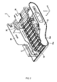
- FIG. 2 is a perspective view showing the interior structure of the test piece analyzer of the embodiment of the invention.
- FIG. 3 is a side view schematically showing the interior structure of the test piece analyzer of the embodiment of the invention.
- the XYZ orthogonal coordinate system shown in FIG. 1 through FIG. 3 is has the direction (second direction) in which the X axis is along the transport direction of the test piece TP (described later), the direction (first direction) in which the Y axis is along the transport direction of the imaging unit 20 (described later), and the Z axis direction set to be mutually perpendicular.
- the test piece analyzer 1 of the embodiment includes a transport unit 10, imaging unit 20, drive part 30, main board 40, display part 50, printing part 60, and housing 70.
- the test piece analyzer 1 images the test piece that has been transported by the transport unit 10 via the imaging unit 20, analyzes the test piece TP using the obtained image, displays the analysis result on the display part 50 or prints the analysis results via the printing part 60.
- the liquid sample to be the object of analysis is urine.
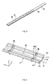
- FIG. 4 is a perspective view showing an example of a test piece used by the test piece analyzer of the embodiment of the invention.
- the test piece TP is a so-called multi test piece that has a flat rod-like substrate SB, and a plurality of reagent pads PD formed on the one surface of the substrate SB.
- the reagent pads PD absorb the liquid sample (for example, urine) that is the object of analysis, and colors in accordance with the composition of the liquid sample.
- the transport unit 10 includes a plurality of test piece holders 11 for mounting the test piece, and a transport device 12 for transporting the test piece holders, wherein the test piece TP mounted on the test piece holder 11 is transported in the X direction, as shown in FIG. 2 and FIG. 3 .
- FIG. 5 is a perspective view showing the test piece holder of the embodiment of the invention. As shown in FIG. 5 , the test piece holder 11 includes, in the plane view, a rectangular bottom plate 11 a, side plates 11b erected on bilateral edges of the bottom plate 11a, and extension plates 11c extending outward from the top edges of bilateral edges 11b, respectively.
- a pair of rib-like protrusions RB also re formed on the test piece holder 11 in the space in the lengthwise direction (Y direction) of the test piece holder 11.
- the rib-like protrusions RB are provided to prevent the test piece TP from sticking to the test piece holder 11.
- the test piece TP also is arranged on the rib-like protrusions RB without touching the bottom plate 11a of the test piece holder 11, as shown in the drawing.
- the width W1 of the mounting part MP is preferably larger than the width of the test piece TP, so that the test piece TP can be mounted on the test piece holder 11 even when the test piece TP is in an inclined condition relative to the lengthwise direction (Y direction) of the test piece holder 11 as shown in FIG. 5 . In this way the work of mounting the test piece TP on the test piece holder 11 can be easily accomplished.
- the width W1 of the mounting part MP also preferably does not exceed double the width of the test piece TP. If the width W1 of the mounting part MP is too large, it may cause the erroneous mounting of a plurality of test pieces TP.
- test piece holder 11 is preferably constructed of synthetic resin.
- image processing step it is preferable that coloration is a dark color to heighten the contrast with the test piece TP and ensure processing.
- the transport device 12 includes an endless belt 12a, pulley 12b. and pulley 12c.
- the endless belt 12a is a band-like body (or belt-like member) formed in an annular shape.
- a plurality of test piece holders 11 are attached independently of each other to the endless belt 12a. Therefore, the adjacent test piece holders 11 can be arranged in mutual proximity or arranged separated from one another, as shown in FIG. 3 .
- the pulleys 12b and 12c are provided with a spacing in the X direction. Since the endless belt 12a is looped around the pulleys 12b and 12c, the endless belt 12a circulates when the pulley 12c rotates, and the pulley 12b also rotates therewith.
- the mounting position P1 first position where the test piece TP is mounted on the test piece holder 11
- the imaging position P2 second position where the test piece TP is imaged by the imaging unit 20 are separated by a predetermined distance in the X direction.
- the test piece TP seated at the mounting position P1 in the test piece holder 11 is transported to the imaging position P2 by the circulatory travel of the endless belt 12a.
- the time during which the test piece holder 11 moves from mounting position P1 to the imaging position P2 is set so that the reagent pad PD of the test piece TP and the components of the liquid sample will react neither excessively of deficiently, and suitably color the reagent pad PD.
- the imaging unit 20 is provided with a pair of light sources 21, an imaging element 22, and support 23, and is configured to be movable in the Y direction along a pair of guide rails 24 extending in the Y direction above the imaging position P2 (+Z side).
- the light sources 21 and 21 irradiate the test piece TP that has been transported to the imaging position P2 by the transport unit 10.
- the light sources 21 and 21 are respectively arranged obliquely above the imaging position P2, so as to uniformly irradiate the test piece TP and avoiding as much as possible shadowing of the test piece TP by the test piece holder 11 by irradiating the test piece TP obliquely downward from the +X side and -X side.
- the light sources 21 and 21 are provided with light emitting elements such as, for example, a light emitting diode (LED) or laser diode (LD). Since the degree of coloration of the reagent pad PD provided on the test piece TP is measured by the test piece analyzer 1, it is preferable that the light emitting element provided in the light sources 21 and 21 is, for example, a light emitting element that emits white light. One or more light emitting element may be provided in each of the light sources 21 and 21.
- the light sources 21 and 21 are respectively provided with a diffusion panel 21a to equalize the illumination light output from the light sources 21 and 21.
- the imaging element 22 is an imaging element (area sensor) that captures the image (two-dimensional image) of the test piece TP that has been transported to the imaging position P2 by the transport unit 10.
- the imaging element 22 is arranged above (+Z direction) the imaging position P2 with the imaging surface facing the bottom side (-Z side).
- the size of the imaging area of the imaging element 22 is set to a size to image part of the test piece TP disposed at the imaging position P2. This arrangement realizes a compact test piece analyzer 1 by reducing as much as possible the distance between the test piece TP and the imaging element 22.
- the length in the Y direction of the imaging area of the imaging element 22 is set smaller than the length of the test piece TP, for example, a length of about 1/4 the length of the test piece TP.
- the width in the X direction of the imaging area of the imaging element 22 is set larger than the width W1 (refer to FIG. 5 ) of the mounting part MP of the test piece holder 11. As shown in FIG. 5 , this arrangement obtains images of the entire test piece TP even when the test piece TP is inclined relative to the length direction (Y direction) of the test piece holder 11.
- the imaging element 22, for example, is set at approximately 40 mm from the top surface of the bottom plate 11a of the test piece holder 11 disposed at the imaging position P2.
- the length in the Y direction and the width in the X direction of the imaging area of the imaging element 22, for example, are set at approximately 30 mm.
- the numeric values given above are examples only and may be suitably modified according to the specifications of the test piece analyzer 1.
- the imaging element 22 is a two-dimensional RGB color image sensor (area sensor) such as a CCD (charge-coupled device) image sensor, CMOS (complementary metal oxide semiconductor) image sensor and the like.
- the imaging element 22 also may be a two-dimensional monochrome image sensor combined with an RGB filter.
- the support 23 integratedly supports the light sources 21 and 21, and the imaging element 22.
- the relative positional relationships of the light sources 21 and 21, and the imaging element 22 are unchanged when the light sources 21 and 21 and the imaging element 22 are integratedly supported by the support 23. Therefore, the illumination conditions when the imaging element 22 images the test piece TP are unchanged (or substantially unchanged) even when the imaging unit 20 moves in the Y direction along the pair of guide rails 24 and 24.
- the drive part 30 includes a motor (for example, a stepping motor), and drives the transport unit 10 and the imaging unit 20.
- the drive part 30 includes a motor M1 (refer to FIG. 6 ) to rotationally drive the pulley 12c provided in the transport unit 10, and the endless belt 12a circulates when the motor M1 is actuated.
- the drive part 30 also intermittently rotates the pulley 12c, and intermittently moves the test piece holder 11 mounted on the endless belt 12a.
- the drive part 30 also includes a motor M2 (refer to FIG. 6 ) used by the imaging unit 20, and the imaging unit 20 moves reciprocatingly in the Y direction along the pair of guide rails 24 and 24 when the motor M2 is actuated.
- the main board 40 is a substrate for mounting a CPU (central processing unit), volatile memory such as RAM (random access memory), nonvolatile memory such as ROM (red only memory), and other electronic components. Control of the operation of the test piece analyzer 1 and processing to analyze the test piece TP are performed by the circuits configuring the electronic components mounted on the main board 40. The structure of the control system of the test piece analyzer 1 is described later.
- the display part 50 includes, for example, a touch panel type liquid crystal display device that has a display function and an operation function to display analysis results of the test piece TP and images of the test piece TP, as well as an operation guide specifying the timing for mounting the test piece TP in the test piece holder 11, and inputting operation information according to the operation when performing an operation on the display screen of the liquid crystal display device.
- the printing part 60 includes, for example, a thermal printer, to print the analysis results of the test piece TP when a print instruction is input through the operation on the display screen of the liquid crystal display device of the display part 50.
- the housing 70 has an exterior part 71 and a pull-out part 72.
- the exterior part 71 is configured by a top panel 71 a and a bottom panel 71 b, and the previously mentioned transport unit 10, imaging unit 20, drive part 30, and main board 40 and the like are accommodated in the interior space between the top panel 71 a and the bottom panel 72b.
- a pull-out port 70a for pulling out the transport unit 10 is formed in the side part (side part on the -Y side) of the exterior part 71.
- a mounting port OP that is, and opening that exposes at least part of the test piece holder 11 at the mounting position P1, is formed in the top panel 71a of the exterior part 71.
- the shape of the mounting port OP is a slit shape extending along the Y direction. Specifically, the mounting port OP is formed to expose at least part of the top surface (refer to FIG. 5 ) of the bottom plate 11 a of the test piece holder 11 at the mounting position P1.
- the width (dimension in the X direction) of the mounting port OP is formed larger than the width of the test piece TP.
- the width of the mounting port OP is set to double the width of the test piece TP.
- the test piece TP can be mounted on the test piece holder 11 even when the orientation of the test piece TP is inclined relative to the Y direction (refer to FIG. 5 ) in plane view since the width of the mounting port OP is larger than the width of the test piece TP. In this way the work of mounting the test piece TP on the test piece holder 11 can be easily accomplished.
- the pull-out part 72 includes a support member (not shown in the drawing) that supports the transport unit 10, and the exterior panel 72a that covers substantially the entirety of the pull-out port 70a.
- the pull-out part 72 is a separate from the exterior part 71, and is accommodated within the exterior part 71 when the transport unit 10 is housed in the exterior part 71.
- the pull-out part 72 and the transport unit 10 also are freely and integratedly placed in and taken out of the exterior part 71 through the pull-out port 70a.
- FIG. 6 is a block diagram showing the structure of the control system of the test piece analyzer of the embodiment of the invention.
- the block diagram corresponds to the structures shown in FIGS. 1 through 3 and is denoted by identical reference numbers.
- the test piece analyzer 1 is provided with a controller 81, image processing part 82, and analyzing part 83 in addition to the imaging unit 20, drive part 30, display part 50, and printing part 60.
- the motor M1 that drives the transport unit 10 (omitted in FIG. 6 ), and the motor M2 that moves the imaging unit 20 in the Y direction are provided in the drive part 30.
- the controller 81, image processing part 82, and analyzing part 83 are realized by having the CPU (not shown in the drawing) provided on the previously mentioned main board 40 execute programs to realize the various functions. That is, the controller 81, image processing part 82, and analyzing part 83 are realized by the cooperating hardware and software resources. The controller 81, image processing part 82, and analyzing part 83 also may be realized by dedicated hardware.
- the controller 81 generally has overall control of the operations of the test piece analyzer 1. Specifically, the controller 81 controls the motor M1 provided in the drive part 30 to drive the transport unit 10, and controls the motor Mr provided in the drive part 30 to move the imaging unit 20 in the Y direction. The controller 81 also controls the emission and non-emission of the light sources 21 provided in the imaging unit 20, and controls the imaging element 22 provided in the imaging unit 20 to capture an image of the test piece TP. The controller 81 also controls the start timing of the processes performed by the image processing part 82 and the analyzing part 83. The controller 81 also performs display controls of the display part 50, and printing controls of the printing part 60.
- the image processing part 82 performs image processing on the plurality of images (hereinafter referred to as "partial images") obtained by imaging the test piece TP via the imaging element 22 while changing the position in the Y direction. Specifically, the image processing part 82 performs the processes (1) through (3) below.
- the "correction process” above is a process for correcting the brightness of the partial images using a brightness correction table (a table for correcting irregular brightness within the imaging area of the imaging element 22) provided in the image processing part 82.
- the brightness within the imaging area of the imaging element 22 becomes irregular due to the optical system (light sources 21, lenses not shown in the drawings and the like), for example, brightness may be different in the center part and the periphery.
- the "correction process” above is performed to correct this brightness irregularity, and improve the measurement accuracy of the degree of coloration of the reagent pads PD provided on the test piece TP.
- the brightness correction table TB also is a two-dimensional table that associates the amount of brightness correction, and the position in the Y direction and X direction within the imaging area of the imaging element 22.
- the brightness correction table TB is prepared, for example, by installing a reference plate (for example, a white color reference plate) in the test piece analyzer 1 before shipment, and using the images obtained by imaging this reference plate via element 22.
- the "combining process” above is a process for obtaining an image that includes the entire test piece TP (referred to as “composite image” below) by combining the plurality of partial images.
- the partial images are images obtained by imaging parts of the test piece TP, and the test piece TP cannot be analyzed by the analyzing part 83 using the partial images alone.
- the "combining process” is performed to enable analysis of the test piece TP by the analyzing part 83.
- the “extraction process” above is a process for extracting the image of the test piece TP (referred to as “extraction image” below) from the composite image obtained through the “combining process”. That is, the “extraction process” is a process that extracts only the image of the test piece TP contained in the composite image, and eliminates the image that is not the test piece TP (for example, the image of the test piece holder 11). This process is performed to enable analysis of the test piece TP by the analyzing part 83 without performing complex image processing even when the test piece TP is inclined relative to the length direction (Y direction) of the test piece holder 11.
- the analyzing part 83 measures the degree of coloration of the reagent pad PD provided on the test piece TP using the image previously subjected to each of the above processes (correction process, combining process, extraction process) by the image processing part 82, and performs concentration analyses of the sugar, protein, and occult blood in the urine. Detailed description of the analyses performed by the analyzing part 83 is omitted since it is well known.
- test piece analyzer 1 of the above configuration is described below.
- the controller 81 controls the motor M1 of the drive part 30 to intermittently rotate the pulley 12c provided in the transport unit 10. In this way the endless belt 12a provided in the transport unit 10 intermittently circulates in the arrow direction shown in FIG. 3 , and intermittently moves the test piece holder 11 mounted on the endless belt 12a.
- test piece TP that is, the test piece TP that has absorbed urine in the reagent pad PD
- test piece TP mounted on the test piece holder 11 is transported in the +X direction by moving the test piece holder 11.
- the test piece TP also is transported with the reagent pad PD facing upward (+Z side), and the reagent pad PD is colored through the reaction of the urine components and the reagent pad PD of the test piece TP.
- the motor M2 of the drive part 30, and light sources 21 of the imaging unit 20, and imaging element 22 are controlled by the controller 81 as shown in FIG. 6 .
- the imaging unit 20 is moved in the Y direction along the guide rails 24 and 24, the operation of imaging the test piece TP is performed by the imaging element 22, all under the control of the controller 81.
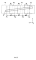
- FIG. 7 illustrates the situation of imaging the test piece by the test piece analyzer of the embodiment of the invention.
- the imaging unit 20 that is first positioned at the home position and is moved in the Y direction to the first imaging position P11 shown in FIG. 7 by the control of the controller 81.
- the home position also is a reference position of the imaging unit 20, and is set, for example, at the end position on the +Y side of the movement range of the imaging unit 20.
- the imaging unit 20 When the imaging unit 20 is positioned at the imaging position P11, the light sources 21 of the imaging unit 20 emit light, and a partial image (specifically, the image within the imaging range A1 shown in FIG. 7 ) of the test piece TP is captured through the control of the controller 81.
- the imaging at imaging position P11 is completed, the light sources 21 of the imaging unit 20 are shut off, and the imaging unit 20 disposed at the imaging position P11 is moved in the -Y direction to the imaging position P12 shown in FIG. 7 through the control of the controller 81.
- the imaging unit 20 When the imaging unit 20 is positioned at the imaging position P12, the light sources 21 of the imaging unit 20 emit light, and another partial image (specifically, the image within the imaging range A2 shown in FIG. 7 ) of the test piece TP is captured through the control of the controller 81.
- the imaging at imaging position P12 When the imaging at imaging position P12 is completed, the light sources 21 of the imaging unit 20 are shut off, and the imaging unit 20 disposed at the imaging position P12 is moved in the -Y direction to the imaging position P13 shown in FIG. 7 through the control of the controller 81.
- the imaging unit 20 When the imaging unit 20 is positioned at the imaging position P 13, the light sources 21 of the imaging unit 20 emit light, and another partial image (specifically, the image within the imaging range A3 shown in FIG. 7 ) of the test piece TP is captured through the control of the controller 81.
- the imaging at imaging position P13 When the imaging at imaging position P13 is completed, the light sources 21 of the imaging unit 20 are shut off, and the imaging unit 20 disposed at the imaging position P13 is moved in the -Y direction to the imaging position P14 shown in FIG. 7 through the control of the controller 81.
- the light sources 21 of the imaging unit 20 emit light, and another partial image (specifically, the image within the imaging range A4 shown in FIG. 7 ) of the test piece TP is captured through the control of the controller 81.
- the light sources 21 of the imaging unit 20 are shut off, and the imaging unit 20 disposed at the imaging position P 14 is moved in the +Y direction to the home position (not shown in the drawing) through the control of the controller 81. In this way the test piece TP is imaged.
- the light sources 21 of the imaging unit 20 also may emit light from the start to the completion of the imaging of the test piece TP.
- the distance separating imaging position P11 and imaging position P12 is set at ⁇ Y1 to create an overlap part Q1 of the imaging area A1 and imaging area A2.
- the distance separating imaging position P12 and imaging position P13 also is set at ⁇ Y1 to create an overlap part Q2 of the imaging area A2 and imaging area A3.
- the width of the overlap parts Q1 and Q2 also are identical.
- the distance ⁇ Y2 separating imaging point P13 and imaging point P 14 is set to a distance shorter than the distance ⁇ Y1 from the relationships of making the test piece analyzer 1 compact.
- the width of the overlap part Q3 is set larger than the width of the overlap parts Q1 and Q2 although the overlap part Q3 is created by the overlapping of the imaging area A3 and imaging area A4.
- the image processing part 82 performs the previously mentioned combining process in consideration of the different width of the overlap part Q3 relative to the overlap parts Q1 and Q2.
- the creation of the overlap parts Q1 through Q3 also is to avoid creating a non-imaged part of the test piece TP due to the partial imaging of the test piece TP by the imaging element 22.
- FIG. 8 illustrates the image processing performed by the test piece analyzer of the embodiment of the invention.
- FIG. 8(A) through (D) respectively show examples of partial images G11 through G14 captured at imaging positions P11 through P 14 shown in FIG. 7 .
- FIG. 8 (E) shows the composite image G20 obtained by combining the partial images G11 through G 14.
- FIG. 8 (F) shows the extraction image G30 extracted from the composite image G20.
- FIG. 9 illustrates the principle of the correction process performed by the test piece analyzer of the embodiment of the invention.
- the horizontal axis of the graph shown in FIG. 9 represents the position (position in the X direction or position in the Y direction) within the imaging area of the imaging element 22.
- the vertical axis of the graph shown in FIG. 9 represents the brightness or the size of the correction value.
- the curve labeled L0 in FIG. 9 is a curve representing an example of the brightness distribution of the image obtained by imaging the reference plate (that is, the reference plate used to create the brightness correction table TB before the test piece analyzer 1 is shipped).
- FIG. 9 shows a unidimensional brightness distribution (for example, brightness distribution in the Y direction) of the image obtained by imaging the reference plate to simplify comprehension.
- the curve labeled L1 in FIG. 9 is obtained by calculating the moving average of the curve L0 to eliminate the influence of noise.
- the curve L1 also may be referred to as a curve representing the brightness distribution within the imaging field of view of the imaging element 22.
- the brightness of the imaging field of view of the imaging element 22 has a distribution that is highest in the center area and lowest at the periphery.
- the brightness distribution of the imaging field of view of the imaging element 22 is substantially the same as that of curve L1 in both the X direction and Y direction.
- the curve labeled L10 in FIG. 9 is an example of the correction values of the brightness correction table TB created using the curve L1. As shown in FIG. 9 , the correction values of the brightness correction table TB are set so that the lowest values are in the center area and the highest values are in the periphery of the imaging field of view of the imaging element 22. That is, the correction values of the brightness correction table TB are set to the reverse distribution relative to the distribution of curve L1.
- the curve labeled L20 in FIG. 9 is corrected brightness distribution (curve L0) of the image obtained by imaging the reference board using the brightness correction table TB.
- curve L0 it can be understood that the brightness is substantially constant within the field of view of the imaging element 22 although there are slight fluctuations due to noise.
- the image processing part 82 corrects the brightness of each partial image G11 through G14 using the brightness correction table TB.
- the image processing part 82 performs the combining process to combine the corrected partial images G11 through G14 and obtain the composite image G20 that includes the entire test piece TP.
- the imaging areas A1 through A4 at imaging positions P11 through P14 are set to create overlap parts Q1 through Q3. Therefore, two partial images are obtained that image the same part of the test piece TP.
- the partial image G11 shown in FIG. 8 (A) and the partial image G12 shown in FIG. 8 (B) include the image of the reagent pad PD of the test piece TP.
- the image processing part 82 combines the partial images G11 through G14 so as to obtain an image of the successive entire test piece TP and does not include the same partial images of the test piece TP. For example, the image processing part 82 performs the combining process to cutout the regions (regions R11 through R14 shown in FIG. 8 (A) through (D) ) excluding areas equivalent to half the width of the overlap parts Q1 and Q2 shown in FIG. 7 from the bilateral ends of each of the partial images G11 through G14. As described using FIG.
- the image processing part 82 performs the extraction process to extract the extraction image G30 from the composite image G20. For example, a process is performed to detect the edges of the image of the test piece TP and extract the extraction image G30 after performing a Hough transform on the composite image G20 shown in FIG. 8 (E) , extracting a rectangular shape representing the outer edge of the test piece TP, and rotating the composite image G20 based on the incline of the extracted rectangular shape.
- the extraction image G30 that was extracted by the image processing part 82 is input to the analyzing part 83 through the controller 81 shown in FIG. 6 , the degree of coloration of the reagent pad PD provided on the test piece TP is measured, and concentration analyses are performed for the sugar, protein, occult blood and the like contained in the urine.
- the analysis results of the analyzing part 83 are output to the controller 81, and displayed on the display part 50 or printed by the printing part 60 under the control of the controller 81.
- the operator also performs the work of immersing the test piece TP in the urine liquid sample, and mounting the test piece TP on the test piece holder 11 at the mounting position P1 through the mounting port OP at constant time intervals (for example, every 10 seconds). Then the test pieces TP are sequentially transported to the imaging position P2 while mounted in adjacent test piece holders 11 as shown in FIG. 10.
- FIG. 10 shows the situation of transporting a plurality of test piece in the embodiment of the invention.
- test pieces TP that are transported to the imaging position P2 are sequentially imaged by the imaging unit 20, and sequentially analyzed based on the acquired image. In this way analysis of the plurality of test pieces TP is performed sequentially. As shown in FIG. 10 , although the test pieces TP are mounted in various states on the test piece holder 11, analysis can be performed insofar as the test piece TP is mounted on the mounting part MP of the test piece holder 11.
- the embodiment described above includes a light source 21 to irradiate the test piece TP, and an imaging unit 20 provided with an imaging element 22 in which the size of the imaging area is set to image part of the test piece TP, and combines a plurality of partial images G11 through G14 obtained by the imaging element 22 images the test piece TP while changing the position of the imaging unit 20 so as to obtain a composite image G20 that includes the entire test piece TP. Therefore, the test piece analyzer 1 can be made compactly, and the test piece TP can be analyzed when obliquely mounted in the test piece holder 11.
- the process of imaging a single test piece TP multiple times this way requires time compared to imaging the entire test piece TP once.
- the processing power of the test piece analyzer 1 is not adversely impacted because the time needed for imaging is set to be less than the reaction time of the next test piece TP to be imaged.
- the test piece TP positioned at the imaging position P2 is irradiated obliquely downward from the +X side and -X side, respectively, and brightness correction is performed using the brightness correction table relative to the partial images G11 through G14 that were acquired by the imaging element 22.
- the brightness can be inexpensively equalized with high precision without and accompanying substantial cost increase.
- only the image of the test piece TP is extracted as the extraction image G30 from the composite image G20. In this way the test piece TP can be analyzed without complex image processing even when the test piece TP is mounted obliquely in the test piece holder 11.
- the width W1 of the mounting part MP of the test piece holder 11 is set larger than the width of the test piece TP, for example, the width W1 is set at approximately double the width of the test piece TP. Therefore, the operator can easily perform the work of mounting the test piece TP on the test piece holder 11, and the work load of the operator is reduced relative to conventional arrangements.
- test piece analyzer and test piece analyzing method of the embodiment of the invention have been described above, however, the invention is not limited to the above embodiments and may be freely modified within the scope of the claims.
- urine is mentioned as the liquid sample targeted for analysis in the embodiment, the liquid sample also may be a liquid other than urine (for example, blood, body fluids, other liquid).
- a line sensor also may be used as the imaging element.
- the brightness correction table TB need not necessarily be used when correcting the brightness of the partial images G11 through G 14, inasmuch as brightness correction also may be performed using, for example, correction functions and the like.
- the above embodiment is described in terms of example in which regions (regions R11 through R14 shown in FIG. 8 (A) through (D) ) required for combination from the partial images G11 through G 14 are cutout, and the cutout images are connected together to obtain the composite image G20.
- the composite image G20 also may be obtained by overlaying partial images G11 through G14 similar to the imaged areas A1 through A1 shown in FIG. 7 , and connecting the overlaid partial images G11 through G14,
- the test piece TP also may be imaged more than four times.
- the number of imagings of the test piece TP is roughly determined by the size of the imaging area of the imaging element 22. Therefore, the number of imagings of the test piece TP tends to be greater when a more compact test piece analyzer 1 is required.
Landscapes
- Physics & Mathematics (AREA)
- Health & Medical Sciences (AREA)
- Life Sciences & Earth Sciences (AREA)
- Chemical & Material Sciences (AREA)
- General Physics & Mathematics (AREA)
- Analytical Chemistry (AREA)
- Biochemistry (AREA)
- General Health & Medical Sciences (AREA)
- Immunology (AREA)
- Pathology (AREA)
- Molecular Biology (AREA)
- Engineering & Computer Science (AREA)
- Spectroscopy & Molecular Physics (AREA)
- Plasma & Fusion (AREA)
- Chemical Kinetics & Catalysis (AREA)
- Investigating Or Analysing Materials By The Use Of Chemical Reactions (AREA)
- Investigating Or Analysing Materials By Optical Means (AREA)
- Theoretical Computer Science (AREA)
- Investigating Or Analysing Biological Materials (AREA)
- Automatic Analysis And Handling Materials Therefor (AREA)
Abstract
Description
- The invention relates to a test piece analyzing apparatus and test piece analyzing method.
- Component analysis has been performed on liquid samples using a test piece provided with a reagent pad in the fields of clinical examinations, food analysis, and other fields. For example, in clinical examinations using urine as liquid samples, concentration analyses are performed for sugar, protein, occult blood and the like using a flat rod-like test piece (multi test piece) provided with a plurality of types of reagent pads by measuring the degree of coloration of each test pad when urine has been absorbed by the reagent pad. Although the degree of coloration of the reagent pad also can be measured visually, a test piece analyzer may be used to efficiently perform high precision measurements.
-
Japanese Patent Application Publication No. 2005-90969 - The test piece analyzer disclosed in
Japanese Patent Application Publication No. 2005-90969 - A problem arises with such test piece analyzers in that the apparatus becomes enlarged and difficult to make more compact due to the necessity of maintaining the distance between the test piece and the line sensor when capturing the image of the entire test piece at one time. Consider that although it is possible to shorten the distance between test piece and line sensor if using a line sensor of approximately the same length as the test piece or longer, this is unrealistic from a cost perspective.
- A conventional test piece analyzer is designed so that the width of the mounting part of the test piece analyzer on which the test piece is mounted is substantially the same as the width of the test piece, and when a operator mounts a test piece on the mounting part, the longitudinal direction of the test piece substantially matches the longitudinal direction of the line sensor. However, in a conventional test piece analyzer the operator must perform the work of mounting the test piece on the mounting part paying attention until the test is completed because the width of the mounting part is substantially the same as the width of the test piece. From the perspective of ease of work of the operator, it is desirable that the test piece analyzer is capable of performing analysis even though the test piece is inclined.
- In view of this information, an object of the invention is to provide a test piece analyzer and test piece analyzing method that is compact and capable of performing analysis even when the test piece is mounted inclined.
- To solve these problems, the test piece analyzer of the invention provides, in a test piece analyzer (1) that analyzes a test piece using a captured image of the test piece (TP) provided with reagent pads (PD), a test piece holder (11) including a mounting part (MP) for mounting the test piece, an imaging unit (20) configured so that the width of the imaging area is greater than the width of the mounting part in the lateral direction, wherein the imaging unit sequentially images the test piece along the longitudinal direction of the mounting part.
- The test piece analyzing method of the invention analyzes a test piece using an image obtained by imaging the test piece (TP) provided with reagent pads (PD). The method sequentially images the test piece mounted on the mounting part along the longitudinal direction of the mounting part by an imaging unit (2) configured so that the width of the imaging area is greater than the width of the mounting part (MP).
- According to the invention, there is an effect of making the analyzer more compact by making it possible to analyze a test piece mounted obliquely.
-
-
FIG. 1 is a perspective view showing the exterior of the test piece analyzer of an embodiment of the invention; -
FIG. 2 is a perspective view showing the interior structure of the test piece analyzer of the embodiment of the invention; -
FIG. 3 is a side view schematically showing the interior structure of the test piece analyzer of the embodiment of the invention; -
FIG. 4 is a perspective view showing an example of a test piece used by the test piece analyzer of the embodiment of the invention; -
FIG. 5 is a perspective view showing the test piece holder of the embodiment of the invention; -
FIG. 6 is a block diagram showing the structure of the control system of the test piece analyzer of the embodiment of the invention; -
FIG. 7 illustrates the situation of imaging the test piece by the test piece analyzer of the embodiment of the invention; -
FIG. 8 illustrates the image processing performed by the test piece analyzer of the embodiment of the invention; -
FIG. 9 illustrates the principle of the correction process performed by the test piece analyzer of the embodiment of the invention; and -
FIG. 10 shows the situation of transporting a plurality of test piece in the embodiment of the invention. - The test piece analyzer and test piece analyzing method of the embodiments of the invention are described in detail below referring to the drawings. In the following description, the positional relationships of every part are described while referring to the XYZ orthogonal coordinate system set in the drawings as necessary. The origin point of the XYZ orthogonal coordinate system shown in each drawing is not fixed and may change as appropriate for the convenience of the description.
-
FIG. 1 is a perspective view showing the exterior of the test piece analyzer of an embodiment of the invention.FIG. 2 is a perspective view showing the interior structure of the test piece analyzer of the embodiment of the invention.FIG. 3 is a side view schematically showing the interior structure of the test piece analyzer of the embodiment of the invention. The XYZ orthogonal coordinate system shown inFIG. 1 through FIG. 3 is has the direction (second direction) in which the X axis is along the transport direction of the test piece TP (described later), the direction (first direction) in which the Y axis is along the transport direction of the imaging unit 20 (described later), and the Z axis direction set to be mutually perpendicular. - As shown in
FIG. 1 through FIG. 3 , the test piece analyzer 1 of the embodiment includes atransport unit 10,imaging unit 20,drive part 30,main board 40, displaypart 50,printing part 60, andhousing 70. The test piece analyzer 1 images the test piece that has been transported by thetransport unit 10 via theimaging unit 20, analyzes the test piece TP using the obtained image, displays the analysis result on thedisplay part 50 or prints the analysis results via theprinting part 60. In this embodiment, the liquid sample to be the object of analysis is urine. - The test piece TP used in the test piece analyzer 1 is briefly described below.
FIG. 4 is a perspective view showing an example of a test piece used by the test piece analyzer of the embodiment of the invention. As shown inFIG. 4 , the test piece TP is a so-called multi test piece that has a flat rod-like substrate SB, and a plurality of reagent pads PD formed on the one surface of the substrate SB. The reagent pads PD absorb the liquid sample (for example, urine) that is the object of analysis, and colors in accordance with the composition of the liquid sample. - The
transport unit 10 includes a plurality oftest piece holders 11 for mounting the test piece, and atransport device 12 for transporting the test piece holders, wherein the test piece TP mounted on thetest piece holder 11 is transported in the X direction, as shown inFIG. 2 andFIG. 3 .FIG. 5 is a perspective view showing the test piece holder of the embodiment of the invention. As shown inFIG. 5 , thetest piece holder 11 includes, in the plane view, arectangular bottom plate 11 a,side plates 11b erected on bilateral edges of thebottom plate 11a, andextension plates 11c extending outward from the top edges ofbilateral edges 11b, respectively. - As shown in
FIG. 5 , a pair of rib-like protrusions RB also re formed on thetest piece holder 11 in the space in the lengthwise direction (Y direction) of thetest piece holder 11. The rib-like protrusions RB are provided to prevent the test piece TP from sticking to thetest piece holder 11. The test piece TP also is arranged on the rib-like protrusions RB without touching thebottom plate 11a of thetest piece holder 11, as shown in the drawing. - The test piece TP is mounted on the mounting part MP in the area between the
side plates 11b of thetest piece holder 11. Therefore, the width W1 of the mounting part MP is preferably larger than the width of the test piece TP, so that the test piece TP can be mounted on thetest piece holder 11 even when the test piece TP is in an inclined condition relative to the lengthwise direction (Y direction) of thetest piece holder 11 as shown inFIG. 5 . In this way the work of mounting the test piece TP on thetest piece holder 11 can be easily accomplished. The width W1 of the mounting part MP also preferably does not exceed double the width of the test piece TP. If the width W1 of the mounting part MP is too large, it may cause the erroneous mounting of a plurality of test pieces TP. Although the structural material of thetest piece holder 11 is not specifically limited, thetest piece holder 11 is preferably constructed of synthetic resin. In the image processing step (described later), it is preferable that coloration is a dark color to heighten the contrast with the test piece TP and ensure processing. - The
transport device 12 includes anendless belt 12a, pulley 12b. andpulley 12c. Theendless belt 12a is a band-like body (or belt-like member) formed in an annular shape. A plurality oftest piece holders 11 are attached independently of each other to theendless belt 12a. Therefore, the adjacenttest piece holders 11 can be arranged in mutual proximity or arranged separated from one another, as shown inFIG. 3 . Thepulleys endless belt 12a is looped around thepulleys endless belt 12a circulates when thepulley 12c rotates, and thepulley 12b also rotates therewith. - As shown in
FIG. 3 , the mounting position P1 (first position) where the test piece TP is mounted on thetest piece holder 11, and the imaging position P2 (second position) where the test piece TP is imaged by theimaging unit 20 are separated by a predetermined distance in the X direction. The test piece TP seated at the mounting position P1 in thetest piece holder 11 is transported to the imaging position P2 by the circulatory travel of theendless belt 12a. The time during which thetest piece holder 11 moves from mounting position P1 to the imaging position P2 is set so that the reagent pad PD of the test piece TP and the components of the liquid sample will react neither excessively of deficiently, and suitably color the reagent pad PD. - The
imaging unit 20 is provided with a pair oflight sources 21, animaging element 22, andsupport 23, and is configured to be movable in the Y direction along a pair ofguide rails 24 extending in the Y direction above the imaging position P2 (+Z side). Thelight sources transport unit 10. Thelight sources test piece holder 11 by irradiating the test piece TP obliquely downward from the +X side and -X side. - The
light sources light sources light sources light sources diffusion panel 21a to equalize the illumination light output from thelight sources - The
imaging element 22 is an imaging element (area sensor) that captures the image (two-dimensional image) of the test piece TP that has been transported to the imaging position P2 by thetransport unit 10. Theimaging element 22 is arranged above (+Z direction) the imaging position P2 with the imaging surface facing the bottom side (-Z side). The size of the imaging area of theimaging element 22 is set to a size to image part of the test piece TP disposed at the imaging position P2. This arrangement realizes a compact test piece analyzer 1 by reducing as much as possible the distance between the test piece TP and theimaging element 22. - Specifically, the length in the Y direction of the imaging area of the
imaging element 22 is set smaller than the length of the test piece TP, for example, a length of about 1/4 the length of the test piece TP. The width in the X direction of the imaging area of theimaging element 22 is set larger than the width W1 (refer toFIG. 5 ) of the mounting part MP of thetest piece holder 11. As shown inFIG. 5 , this arrangement obtains images of the entire test piece TP even when the test piece TP is inclined relative to the length direction (Y direction) of thetest piece holder 11. - The
imaging element 22, for example, is set at approximately 40 mm from the top surface of thebottom plate 11a of thetest piece holder 11 disposed at the imaging position P2. The length in the Y direction and the width in the X direction of the imaging area of theimaging element 22, for example, are set at approximately 30 mm. The numeric values given above are examples only and may be suitably modified according to the specifications of the test piece analyzer 1. - The
imaging element 22 is a two-dimensional RGB color image sensor (area sensor) such as a CCD (charge-coupled device) image sensor, CMOS (complementary metal oxide semiconductor) image sensor and the like. Theimaging element 22 also may be a two-dimensional monochrome image sensor combined with an RGB filter. - The
support 23 integratedly supports thelight sources imaging element 22. The relative positional relationships of thelight sources imaging element 22 are unchanged when thelight sources imaging element 22 are integratedly supported by thesupport 23. Therefore, the illumination conditions when theimaging element 22 images the test piece TP are unchanged (or substantially unchanged) even when theimaging unit 20 moves in the Y direction along the pair ofguide rails - The
drive part 30 includes a motor (for example, a stepping motor), and drives thetransport unit 10 and theimaging unit 20. Specifically, thedrive part 30 includes a motor M1 (refer toFIG. 6 ) to rotationally drive thepulley 12c provided in thetransport unit 10, and theendless belt 12a circulates when the motor M1 is actuated. Although details are provided later, thedrive part 30 also intermittently rotates thepulley 12c, and intermittently moves thetest piece holder 11 mounted on theendless belt 12a. Thedrive part 30 also includes a motor M2 (refer toFIG. 6 ) used by theimaging unit 20, and theimaging unit 20 moves reciprocatingly in the Y direction along the pair ofguide rails - The
main board 40 is a substrate for mounting a CPU (central processing unit), volatile memory such as RAM (random access memory), nonvolatile memory such as ROM (red only memory), and other electronic components. Control of the operation of the test piece analyzer 1 and processing to analyze the test piece TP are performed by the circuits configuring the electronic components mounted on themain board 40. The structure of the control system of the test piece analyzer 1 is described later. - The
display part 50 includes, for example, a touch panel type liquid crystal display device that has a display function and an operation function to display analysis results of the test piece TP and images of the test piece TP, as well as an operation guide specifying the timing for mounting the test piece TP in thetest piece holder 11, and inputting operation information according to the operation when performing an operation on the display screen of the liquid crystal display device. Theprinting part 60 includes, for example, a thermal printer, to print the analysis results of the test piece TP when a print instruction is input through the operation on the display screen of the liquid crystal display device of thedisplay part 50. - The
housing 70 has anexterior part 71 and a pull-outpart 72. Theexterior part 71 is configured by atop panel 71 a and abottom panel 71 b, and the previously mentionedtransport unit 10,imaging unit 20, drivepart 30, andmain board 40 and the like are accommodated in the interior space between thetop panel 71 a and the bottom panel 72b. A pull-outport 70a for pulling out thetransport unit 10 is formed in the side part (side part on the -Y side) of theexterior part 71. - A mounting port OP, that is, and opening that exposes at least part of the
test piece holder 11 at the mounting position P1, is formed in thetop panel 71a of theexterior part 71. The shape of the mounting port OP is a slit shape extending along the Y direction. Specifically, the mounting port OP is formed to expose at least part of the top surface (refer toFIG. 5 ) of thebottom plate 11 a of thetest piece holder 11 at the mounting position P1. - The width (dimension in the X direction) of the mounting port OP is formed larger than the width of the test piece TP. For example, the width of the mounting port OP is set to double the width of the test piece TP. The test piece TP can be mounted on the
test piece holder 11 even when the orientation of the test piece TP is inclined relative to the Y direction (refer toFIG. 5 ) in plane view since the width of the mounting port OP is larger than the width of the test piece TP. In this way the work of mounting the test piece TP on thetest piece holder 11 can be easily accomplished. - The pull-out
part 72 includes a support member (not shown in the drawing) that supports thetransport unit 10, and theexterior panel 72a that covers substantially the entirety of the pull-outport 70a. The pull-outpart 72 is a separate from theexterior part 71, and is accommodated within theexterior part 71 when thetransport unit 10 is housed in theexterior part 71. The pull-outpart 72 and thetransport unit 10 also are freely and integratedly placed in and taken out of theexterior part 71 through the pull-outport 70a. -
FIG. 6 is a block diagram showing the structure of the control system of the test piece analyzer of the embodiment of the invention. InFIG. 6 , the block diagram corresponds to the structures shown inFIGS. 1 through 3 and is denoted by identical reference numbers. As shown inFIG. 6 , the test piece analyzer 1 is provided with acontroller 81,image processing part 82, and analyzingpart 83 in addition to theimaging unit 20, drivepart 30,display part 50, and printingpart 60. The motor M1 that drives the transport unit 10 (omitted inFIG. 6 ), and the motor M2 that moves theimaging unit 20 in the Y direction are provided in thedrive part 30. - The
controller 81,image processing part 82, and analyzingpart 83 are realized by having the CPU (not shown in the drawing) provided on the previously mentionedmain board 40 execute programs to realize the various functions. That is, thecontroller 81,image processing part 82, and analyzingpart 83 are realized by the cooperating hardware and software resources. Thecontroller 81,image processing part 82, and analyzingpart 83 also may be realized by dedicated hardware. - The
controller 81 generally has overall control of the operations of the test piece analyzer 1. Specifically, thecontroller 81 controls the motor M1 provided in thedrive part 30 to drive thetransport unit 10, and controls the motor Mr provided in thedrive part 30 to move theimaging unit 20 in the Y direction. Thecontroller 81 also controls the emission and non-emission of thelight sources 21 provided in theimaging unit 20, and controls theimaging element 22 provided in theimaging unit 20 to capture an image of the test piece TP. Thecontroller 81 also controls the start timing of the processes performed by theimage processing part 82 and the analyzingpart 83. Thecontroller 81 also performs display controls of thedisplay part 50, and printing controls of theprinting part 60. - The
image processing part 82 performs image processing on the plurality of images (hereinafter referred to as "partial images") obtained by imaging the test piece TP via theimaging element 22 while changing the position in the Y direction. Specifically, theimage processing part 82 performs the processes (1) through (3) below. - (1) Correction process
- (2) Combining process
- (3) Extraction process
- The "correction process" above is a process for correcting the brightness of the partial images using a brightness correction table (a table for correcting irregular brightness within the imaging area of the imaging element 22) provided in the
image processing part 82. The brightness within the imaging area of theimaging element 22 becomes irregular due to the optical system (light sources 21, lenses not shown in the drawings and the like), for example, brightness may be different in the center part and the periphery. The "correction process" above is performed to correct this brightness irregularity, and improve the measurement accuracy of the degree of coloration of the reagent pads PD provided on the test piece TP. - As described above, the illumination conditions when the test piece TP is imaged by the
imaging element 22 are unchanged (or substantially unchanged) even when theimaging unit 20 is moved in the Y direction along the pair of guide rails 24. Therefore, the "correction process" relative to the plurality of partial images is performed using a single brightness correction table TB. The brightness correction table TB also is a two-dimensional table that associates the amount of brightness correction, and the position in the Y direction and X direction within the imaging area of theimaging element 22. The brightness correction table TB is prepared, for example, by installing a reference plate (for example, a white color reference plate) in the test piece analyzer 1 before shipment, and using the images obtained by imaging this reference plate viaelement 22. - The "combining process" above is a process for obtaining an image that includes the entire test piece TP (referred to as "composite image" below) by combining the plurality of partial images. The partial images are images obtained by imaging parts of the test piece TP, and the test piece TP cannot be analyzed by the analyzing
part 83 using the partial images alone. The "combining process" is performed to enable analysis of the test piece TP by the analyzingpart 83. - The "extraction process" above is a process for extracting the image of the test piece TP (referred to as "extraction image" below) from the composite image obtained through the "combining process". That is, the "extraction process" is a process that extracts only the image of the test piece TP contained in the composite image, and eliminates the image that is not the test piece TP (for example, the image of the test piece holder 11). This process is performed to enable analysis of the test piece TP by the analyzing
part 83 without performing complex image processing even when the test piece TP is inclined relative to the length direction (Y direction) of thetest piece holder 11. - The analyzing
part 83 measures the degree of coloration of the reagent pad PD provided on the test piece TP using the image previously subjected to each of the above processes (correction process, combining process, extraction process) by theimage processing part 82, and performs concentration analyses of the sugar, protein, and occult blood in the urine. Detailed description of the analyses performed by the analyzingpart 83 is omitted since it is well known. - The operation of the test piece analyzer 1 of the above configuration is described below. When the power supply of the test piece analyzer 1 is switched on, the
controller 81 controls the motor M1 of thedrive part 30 to intermittently rotate thepulley 12c provided in thetransport unit 10. In this way theendless belt 12a provided in thetransport unit 10 intermittently circulates in the arrow direction shown inFIG. 3 , and intermittently moves thetest piece holder 11 mounted on theendless belt 12a. - A operator performed the work of immersing the test piece TP in the urine liquid sample, then mounts the test piece TP (that is, the test piece TP that has absorbed urine in the reagent pad PD) on the
test piece holder 11 disposed mounting position P1 through the mounting port OP. Then the test piece TP mounted on thetest piece holder 11 is transported in the +X direction by moving thetest piece holder 11. The test piece TP also is transported with the reagent pad PD facing upward (+Z side), and the reagent pad PD is colored through the reaction of the urine components and the reagent pad PD of the test piece TP. - When the
test piece3 holder 11 with the mounted test piece TP is transported to the imaging position P2, the motor M2 of thedrive part 30, andlight sources 21 of theimaging unit 20, andimaging element 22 are controlled by thecontroller 81 as shown inFIG. 6 . As theimaging unit 20 is moved in the Y direction along the guide rails 24 and 24, the operation of imaging the test piece TP is performed by theimaging element 22, all under the control of thecontroller 81. -
FIG. 7 illustrates the situation of imaging the test piece by the test piece analyzer of the embodiment of the invention. When the operation of imaging the test piece TP starts, theimaging unit 20 that is first positioned at the home position and is moved in the Y direction to the first imaging position P11 shown inFIG. 7 by the control of thecontroller 81. The home position also is a reference position of theimaging unit 20, and is set, for example, at the end position on the +Y side of the movement range of theimaging unit 20. - When the
imaging unit 20 is positioned at the imaging position P11, thelight sources 21 of theimaging unit 20 emit light, and a partial image (specifically, the image within the imaging range A1 shown inFIG. 7 ) of the test piece TP is captured through the control of thecontroller 81. When the imaging at imaging position P11 is completed, thelight sources 21 of theimaging unit 20 are shut off, and theimaging unit 20 disposed at the imaging position P11 is moved in the -Y direction to the imaging position P12 shown inFIG. 7 through the control of thecontroller 81. - When the
imaging unit 20 is positioned at the imaging position P12, thelight sources 21 of theimaging unit 20 emit light, and another partial image (specifically, the image within the imaging range A2 shown inFIG. 7 ) of the test piece TP is captured through the control of thecontroller 81. When the imaging at imaging position P12 is completed, thelight sources 21 of theimaging unit 20 are shut off, and theimaging unit 20 disposed at the imaging position P12 is moved in the -Y direction to the imaging position P13 shown inFIG. 7 through the control of thecontroller 81. - When the
imaging unit 20 is positioned at the imaging position P 13, thelight sources 21 of theimaging unit 20 emit light, and another partial image (specifically, the image within the imaging range A3 shown inFIG. 7 ) of the test piece TP is captured through the control of thecontroller 81. When the imaging at imaging position P13 is completed, thelight sources 21 of theimaging unit 20 are shut off, and theimaging unit 20 disposed at the imaging position P13 is moved in the -Y direction to the imaging position P14 shown inFIG. 7 through the control of thecontroller 81. - When the
imaging unit 20 is positioned at the imaging position P 14, thelight sources 21 of theimaging unit 20 emit light, and another partial image (specifically, the image within the imaging range A4 shown inFIG. 7 ) of the test piece TP is captured through the control of thecontroller 81. When the imaging at imaging position P 14 is completed, thelight sources 21 of theimaging unit 20 are shut off, and theimaging unit 20 disposed at the imaging position P 14 is moved in the +Y direction to the home position (not shown in the drawing) through the control of thecontroller 81. In this way the test piece TP is imaged. Thelight sources 21 of theimaging unit 20 also may emit light from the start to the completion of the imaging of the test piece TP. - As shown in
FIG. 7 , the distance separating imaging position P11 and imaging position P12 is set at ΔY1 to create an overlap part Q1 of the imaging area A1 and imaging area A2. The distance separating imaging position P12 and imaging position P13 also is set at ΔY1 to create an overlap part Q2 of the imaging area A2 and imaging area A3. The width of the overlap parts Q1 and Q2 also are identical. - In contrast, the distance ΔY2 separating imaging point P13 and imaging point P 14 is set to a distance shorter than the distance ΔY1 from the relationships of making the test piece analyzer 1 compact. In this way the width of the overlap part Q3 is set larger than the width of the overlap parts Q1 and Q2 although the overlap part Q3 is created by the overlapping of the imaging area A3 and imaging area A4. Although described in detail later, the
image processing part 82 performs the previously mentioned combining process in consideration of the different width of the overlap part Q3 relative to the overlap parts Q1 and Q2. The creation of the overlap parts Q1 through Q3 also is to avoid creating a non-imaged part of the test piece TP due to the partial imaging of the test piece TP by theimaging element 22. - When the imaging of the test piece TP is completed, the partial images made by the
imaging element 22 are input to theimage processing part 82 through thecontroller 81 as shown inFIG. 6 , and image processing (previously mentioned correction process, combining process, extraction process) is performed on the partial images.FIG. 8 illustrates the image processing performed by the test piece analyzer of the embodiment of the invention.FIG. 8(A) through (D) respectively show examples of partial images G11 through G14 captured at imaging positions P11 through P 14 shown inFIG. 7 .FIG. 8 (E) shows the composite image G20 obtained by combining the partial images G11 through G 14.FIG. 8 (F) shows the extraction image G30 extracted from the composite image G20. - When the image processing starts, the
image processing part 82 first performs the correction process on each of the partial images G11 through G 14 shown inFIG. 8 (A) through (D) .FIG. 9 illustrates the principle of the correction process performed by the test piece analyzer of the embodiment of the invention. The horizontal axis of the graph shown inFIG. 9 represents the position (position in the X direction or position in the Y direction) within the imaging area of theimaging element 22. The vertical axis of the graph shown inFIG. 9 represents the brightness or the size of the correction value. - The curve labeled L0 in
FIG. 9 is a curve representing an example of the brightness distribution of the image obtained by imaging the reference plate (that is, the reference plate used to create the brightness correction table TB before the test piece analyzer 1 is shipped).FIG. 9 shows a unidimensional brightness distribution (for example, brightness distribution in the Y direction) of the image obtained by imaging the reference plate to simplify comprehension. - The curve labeled L1 in
FIG. 9 is obtained by calculating the moving average of the curve L0 to eliminate the influence of noise. The curve L1 also may be referred to as a curve representing the brightness distribution within the imaging field of view of theimaging element 22. When referring to the curve L1, it can be understood that the brightness of the imaging field of view of theimaging element 22 has a distribution that is highest in the center area and lowest at the periphery. The brightness distribution of the imaging field of view of theimaging element 22 is substantially the same as that of curve L1 in both the X direction and Y direction. - The curve labeled L10 in
FIG. 9 is an example of the correction values of the brightness correction table TB created using the curve L1. As shown inFIG. 9 , the correction values of the brightness correction table TB are set so that the lowest values are in the center area and the highest values are in the periphery of the imaging field of view of theimaging element 22. That is, the correction values of the brightness correction table TB are set to the reverse distribution relative to the distribution of curve L1. - The curve labeled L20 in
FIG. 9 is corrected brightness distribution (curve L0) of the image obtained by imaging the reference board using the brightness correction table TB. When referring to the curve L0, it can be understood that the brightness is substantially constant within the field of view of theimaging element 22 although there are slight fluctuations due to noise. Based on this principle, theimage processing part 82 corrects the brightness of each partial image G11 through G14 using the brightness correction table TB. - When the correction processing of each partial image G11 through G14 is completed, the
image processing part 82 performs the combining process to combine the corrected partial images G11 through G14 and obtain the composite image G20 that includes the entire test piece TP. As described usingFIG. 7 , the imaging areas A1 through A4 at imaging positions P11 through P14 are set to create overlap parts Q1 through Q3. Therefore, two partial images are obtained that image the same part of the test piece TP. For example, the partial image G11 shown inFIG. 8 (A) and the partial image G12 shown inFIG. 8 (B) include the image of the reagent pad PD of the test piece TP. - The
image processing part 82 combines the partial images G11 through G14 so as to obtain an image of the successive entire test piece TP and does not include the same partial images of the test piece TP. For example, theimage processing part 82 performs the combining process to cutout the regions (regions R11 through R14 shown inFIG. 8 (A) through (D) ) excluding areas equivalent to half the width of the overlap parts Q1 and Q2 shown inFIG. 7 from the bilateral ends of each of the partial images G11 through G14. As described usingFIG. 7 , however, since the width of the overlap part Q3 is greater than the width of the overlap parts Q1 and Q2, it is necessary to adjust the width by the portion to be excluded at the right end of the partial image G13 and portion to be excluded at the left end of the partial image G14. - When the combining process is completed and the composite image G20 is obtained, the
image processing part 82 performs the extraction process to extract the extraction image G30 from the composite image G20. For example, a process is performed to detect the edges of the image of the test piece TP and extract the extraction image G30 after performing a Hough transform on the composite image G20 shown inFIG. 8 (E) , extracting a rectangular shape representing the outer edge of the test piece TP, and rotating the composite image G20 based on the incline of the extracted rectangular shape. - When the above process is completed, the extraction image G30 that was extracted by the
image processing part 82 is input to the analyzingpart 83 through thecontroller 81 shown inFIG. 6 , the degree of coloration of the reagent pad PD provided on the test piece TP is measured, and concentration analyses are performed for the sugar, protein, occult blood and the like contained in the urine. The analysis results of the analyzingpart 83 are output to thecontroller 81, and displayed on thedisplay part 50 or printed by theprinting part 60 under the control of thecontroller 81. - The operator also performs the work of immersing the test piece TP in the urine liquid sample, and mounting the test piece TP on the
test piece holder 11 at the mounting position P1 through the mounting port OP at constant time intervals (for example, every 10 seconds). Then the test pieces TP are sequentially transported to the imaging position P2 while mounted in adjacenttest piece holders 11 as shown inFIG. 10. FIG. 10 shows the situation of transporting a plurality of test piece in the embodiment of the invention. - The test pieces TP that are transported to the imaging position P2 are sequentially imaged by the
imaging unit 20, and sequentially analyzed based on the acquired image. In this way analysis of the plurality of test pieces TP is performed sequentially. As shown inFIG. 10 , although the test pieces TP are mounted in various states on thetest piece holder 11, analysis can be performed insofar as the test piece TP is mounted on the mounting part MP of thetest piece holder 11. - The embodiment described above includes a
light source 21 to irradiate the test piece TP, and animaging unit 20 provided with animaging element 22 in which the size of the imaging area is set to image part of the test piece TP, and combines a plurality of partial images G11 through G14 obtained by theimaging element 22 images the test piece TP while changing the position of theimaging unit 20 so as to obtain a composite image G20 that includes the entire test piece TP. Therefore, the test piece analyzer 1 can be made compactly, and the test piece TP can be analyzed when obliquely mounted in thetest piece holder 11. - The process of imaging a single test piece TP multiple times this way requires time compared to imaging the entire test piece TP once. However, the processing power of the test piece analyzer 1 is not adversely impacted because the time needed for imaging is set to be less than the reaction time of the next test piece TP to be imaged.
- In this embodiment, the test piece TP positioned at the imaging position P2 is irradiated obliquely downward from the +X side and -X side, respectively, and brightness correction is performed using the brightness correction table relative to the partial images G11 through G14 that were acquired by the
imaging element 22. In this way the brightness can be inexpensively equalized with high precision without and accompanying substantial cost increase. In the embodiment, only the image of the test piece TP is extracted as the extraction image G30 from the composite image G20. In this way the test piece TP can be analyzed without complex image processing even when the test piece TP is mounted obliquely in thetest piece holder 11. - In the above embodiment, the width W1 of the mounting part MP of the
test piece holder 11 is set larger than the width of the test piece TP, for example, the width W1 is set at approximately double the width of the test piece TP. Therefore, the operator can easily perform the work of mounting the test piece TP on thetest piece holder 11, and the work load of the operator is reduced relative to conventional arrangements. - The test piece analyzer and test piece analyzing method of the embodiment of the invention have been described above, however, the invention is not limited to the above embodiments and may be freely modified within the scope of the claims. For example, although urine is mentioned as the liquid sample targeted for analysis in the embodiment, the liquid sample also may be a liquid other than urine (for example, blood, body fluids, other liquid).
- Although an area sensor is used as the
imaging element 22 in the above embodiment, a line sensor also may be used as the imaging element. - An example of correcting the brightness of the partial images G11 through G14 using the brightness correction table TB is described in the embodiment. However, the brightness correction table TB need not necessarily be used when correcting the brightness of the partial images G11 through G 14, inasmuch as brightness correction also may be performed using, for example, correction functions and the like.
- The above embodiment is described in terms of example in which regions (regions R11 through R14 shown in
FIG. 8 (A) through (D) ) required for combination from the partial images G11 through G 14 are cutout, and the cutout images are connected together to obtain the composite image G20. However, the composite image G20 also may be obtained by overlaying partial images G11 through G14 similar to the imaged areas A1 through A1 shown inFIG. 7 , and connecting the overlaid partial images G11 through G14, - The above embodiment has been described by way of example of performing a Hough transform relative to the composite image G20 when extracting the extraction image G30 from the composite image G20. However, a Hough transform need not necessarily be performed on the composite image G20, inasmuch as the extraction image G30 also may be extracted using another method. For example, it also is possible to extract the extraction image G30 by detecting the edges of the image of the test piece TP, and cutting out the composite image G20 along the detected edges.
- Although the above embodiment describes an example of obtaining four partial images G11 through G14 by imaging the test piece TP four times, the test piece TP also may be imaged more than four times. The number of imagings of the test piece TP is roughly determined by the size of the imaging area of the
imaging element 22. Therefore, the number of imagings of the test piece TP tends to be greater when a more compact test piece analyzer 1 is required.
Claims (15)
- A test piece analyzer that analyzes a test piece using a captured image of the test piece provided with reagent pads, the test piece analyzer comprising:a test piece holder with a mounting part for mounting a test piece; andan imaging unit configured so that a width of an imaging area is larger than a width of the mounting part in a lateral direction;wherein the imaging unit sequentially images the test piece along a longitudinal direction of the mounting part.
- The test piece analyzer of claim 1, further comprising: a drive part for moving the imaging unit along the longitudinal direction of the mounting part.
- The test piece analyzer of claim 1 or 2, whereinthe light source comprises a pair of light sources respectively arranged obliquely above the imaging position for imaging the test piece; andthe pair of light sources are respectively configured to irradiate obliquely downward on the test piece arranged at the imaging position.
- The test piece analyzer of any among claims 1 through 3, further comprising: an image processing part that performs a synthesizing process to obtain a composite image that includes the entire test piece by combining a plurality of partial images of the test piece acquired by imaging the test piece.
- The test piece analyzer of claim 4, whereinthe image processing part performs a correction process to correct brightness of the partial images.
- The test piece analyzer of claim 5, whereinthe image processing part comprises a brightness correction table to correct irregular brightness within the imaging area of the imaging unit; andperforms a correction process to correct the brightness of the partial images obtained from the imaging unit using the brightness correction table.
- The test piece analyzer of any among claims 4 through 6, whereinthe image processing part performs an extraction process to extract an image of the test piece from the composite image.
- The test piece analyzer of any among claims 1 through 7, whereinthe imaging unit has a support to integratedly support an imaging element and a light source for illuminating the test piece.
- The test piece analyzer of any among claims 1 through 8, further comprising:a transport unit having the test piece holder, and transports the test piece from a first position to a second position by moving the test piece holder along the lateral direction of the mounting part.
- The test piece analyzer of any among claims 1 through 9, whereinthe width of the mounting part is set larger than the width of the test piece.
- The test piece analyzer of any among claims 1 through 10, wherein a length of the imaging area of the imaging unit in the longitudinal direction of the mounting part is set smaller than a length of the test piece.
- The test piece analyzer of any among claims 1 through 11, whereinthe test piece holder comprises: a bottom plate, and pair of side plates extending from both side edges of the bottom plate;wherein the mounting part is an area between the pair of side plates.
- A test piece analyzing method for analyzing a test piece using a captured image of the test piece provided with reagent pads, the test piece analyzing method comprising:sequentially imaging the test piece mounted on a mounting part along a longitudinal direction of the mounting part by an imaging unit configured so that a width of a imaging area is greater than a width in a lateral direction of the mounting part.
- The test piece analyzing method of claim 13, whereinthe test piece is imaged by the imaging unit while changing the position of the imaging unit comprising a light source to irradiate the test piece and an imaging element configured so the size of the imaging area is set to image part of the test piece, in the step of sequentially imaging the test piece.
- The test piece analyzing method of claims 13 or 14, whereinthe imaging unit is moved along the longitudinal direction of the mounting part in the step of sequentially imaging the test piece.
Applications Claiming Priority (1)
| Application Number | Priority Date | Filing Date | Title |
|---|---|---|---|
| JP2015201502A JP6599721B2 (en) | 2015-10-09 | 2015-10-09 | Test strip analyzer and test strip analysis method |
Publications (2)
| Publication Number | Publication Date |
|---|---|
| EP3153847A1 true EP3153847A1 (en) | 2017-04-12 |
| EP3153847B1 EP3153847B1 (en) | 2020-01-01 |
Family
ID=57133021
Family Applications (1)
| Application Number | Title | Priority Date | Filing Date |
|---|---|---|---|
| EP16192789.2A Active EP3153847B1 (en) | 2015-10-09 | 2016-10-07 | Test piece analyzing apparatus and test piece analyzing method |
Country Status (4)
| Country | Link |
|---|---|
| US (1) | US10019783B2 (en) |
| EP (1) | EP3153847B1 (en) |
| JP (1) | JP6599721B2 (en) |
| CN (1) | CN106970070B (en) |
Families Citing this family (5)
| Publication number | Priority date | Publication date | Assignee | Title |
|---|---|---|---|---|
| JP6921674B2 (en) * | 2017-07-28 | 2021-08-18 | テラメックス株式会社 | Test piece storage container continuous processing device |
| TWI786664B (en) * | 2021-06-04 | 2022-12-11 | 緯創資通股份有限公司 | Image processing apparatus and image-based indicator paper identification method |
| CN115096878A (en) * | 2022-04-06 | 2022-09-23 | 新绎健康科技有限公司 | Detection method and system of test paper convenient to detect |
| CN119757771A (en) | 2023-10-02 | 2025-04-04 | 希森美康株式会社 | Sample analysis device and sample analysis method |
| WO2026028685A1 (en) * | 2024-08-01 | 2026-02-05 | アークレイ株式会社 | Specimen liquid inspection device, program, and recording medium |
Citations (5)
| Publication number | Priority date | Publication date | Assignee | Title |
|---|---|---|---|---|
| JP2005090969A (en) | 2003-09-12 | 2005-04-07 | Terametsukusu Kk | Specimen analyzer |
| EP1801568A1 (en) * | 2005-12-21 | 2007-06-27 | Micronas Holding GmbH | Test strip and method for measuring analyte concentration in a biological fluid sample |
| US20080019596A1 (en) * | 2004-09-16 | 2008-01-24 | Koninklijke Philips Electronics, N.V. | Imaging Method and Apparatus for Analysing Objects |
| EP2385369A1 (en) * | 2010-05-05 | 2011-11-09 | Alverix, Inc. | Assay reader operable to scan a test strip |
| US20150031135A1 (en) * | 2012-03-09 | 2015-01-29 | Siemens Healthcare Diagnostics Inc. | Calibration method for reagent card analyzers |
Family Cites Families (12)
| Publication number | Priority date | Publication date | Assignee | Title |
|---|---|---|---|---|
| JP3559975B2 (en) * | 1992-09-10 | 2004-09-02 | テラメックス株式会社 | Analysis method using test pieces |
| JP3008278B1 (en) * | 1998-08-06 | 2000-02-14 | 株式会社京都第一科学 | Test piece photometer |
| JP2007212261A (en) * | 2006-02-09 | 2007-08-23 | Wako Pure Chem Ind Ltd | Test paper measuring instrument and test paper measuring method |
| GB201105474D0 (en) * | 2011-03-31 | 2011-05-18 | Albagaia Ltd | Testing apparatus |
| US20140028857A1 (en) * | 2011-04-29 | 2014-01-30 | Siemens Healthcare Diagnostics Inc. | High flux collimated illuminator and method of uniform field illumination |
| US9782114B2 (en) * | 2011-08-03 | 2017-10-10 | Intuity Medical, Inc. | Devices and methods for body fluid sampling and analysis |
| US9606103B2 (en) * | 2011-12-16 | 2017-03-28 | Siemens Healthcare Diagnostics Inc. | Waste ramp for reagent cards |
| EP2696193A1 (en) * | 2012-08-06 | 2014-02-12 | Andrew Wheeler | Assay detection systems and methods |
| US20170098137A1 (en) * | 2012-08-08 | 2017-04-06 | Scanadu Incorporated | Method, apparatus and system for detecting and determining compromised reagent pads by quantifying color changes induced by exposure to a hostile environment |
| US9612249B2 (en) * | 2013-02-14 | 2017-04-04 | Siemens Healthcare Diagnostics Inc. | Reduction of false positive on reagent test devices |
| US9863811B2 (en) * | 2014-08-15 | 2018-01-09 | Scanadu Incorporated | Precision luxmeter methods for digital cameras to quantify colors in uncontrolled lighting environments |
| US10890593B2 (en) * | 2015-10-09 | 2021-01-12 | Sysmex Corporation | Test piece mounting body, transport unit, and test piece analyzer |
-
2015
- 2015-10-09 JP JP2015201502A patent/JP6599721B2/en active Active
-
2016
- 2016-10-06 US US15/287,195 patent/US10019783B2/en active Active
- 2016-10-07 EP EP16192789.2A patent/EP3153847B1/en active Active
- 2016-10-09 CN CN201610880210.3A patent/CN106970070B/en active Active
Patent Citations (5)
| Publication number | Priority date | Publication date | Assignee | Title |
|---|---|---|---|---|
| JP2005090969A (en) | 2003-09-12 | 2005-04-07 | Terametsukusu Kk | Specimen analyzer |
| US20080019596A1 (en) * | 2004-09-16 | 2008-01-24 | Koninklijke Philips Electronics, N.V. | Imaging Method and Apparatus for Analysing Objects |
| EP1801568A1 (en) * | 2005-12-21 | 2007-06-27 | Micronas Holding GmbH | Test strip and method for measuring analyte concentration in a biological fluid sample |
| EP2385369A1 (en) * | 2010-05-05 | 2011-11-09 | Alverix, Inc. | Assay reader operable to scan a test strip |
| US20150031135A1 (en) * | 2012-03-09 | 2015-01-29 | Siemens Healthcare Diagnostics Inc. | Calibration method for reagent card analyzers |
Non-Patent Citations (2)
| Title |
|---|
| ANONYMOUS: "Epson Perfection 3490/3590 Photo", 1 August 2005 (2005-08-01), pages 1 - 4, XP055340827, Retrieved from the Internet <URL:http://content.etilize.com/Manufacturer-Brochure/10532850.pdf> [retrieved on 20170131] * |
| T. M. BLICHARZ ET AL: "Use of Colorimetric Test Strips for Monitoring the Effect of Hemodialysis on Salivary Nitrite and Uric Acid in Patients with End-Stage Renal Disease: A Proof of Principle", CLINICAL CHEMISTRY, vol. 54, no. 9, 1 January 2008 (2008-01-01), pages 1473 - 1480, XP055048980, ISSN: 0009-9147, DOI: 10.1373/clinchem.2008.105320 * |
Also Published As
| Publication number | Publication date |
|---|---|
| JP6599721B2 (en) | 2019-10-30 |
| US20170103543A1 (en) | 2017-04-13 |
| JP2017072567A (en) | 2017-04-13 |
| US10019783B2 (en) | 2018-07-10 |
| EP3153847B1 (en) | 2020-01-01 |
| CN106970070B (en) | 2020-06-30 |
| CN106970070A (en) | 2017-07-21 |
Similar Documents
| Publication | Publication Date | Title |
|---|---|---|
| EP3153847B1 (en) | Test piece analyzing apparatus and test piece analyzing method | |
| JP6450700B2 (en) | Board inspection equipment | |
| JP5801004B2 (en) | Calibration method for reagent card analyzer | |
| CN102749444B (en) | Analytical equipment | |
| JP2008235892A (en) | Apparatus and method for evaluation of defect in edge region of wafer | |
| EP2685208A2 (en) | Vision testing device using multigrid pattern | |
| KR101790355B1 (en) | X-ray analyzing apparatus | |
| KR20120058443A (en) | Multi-modal imaging | |
| US20100027873A1 (en) | Board appearance inspection method and device | |
| WO2009090871A1 (en) | Apparatus for inspecting subject to be inspected | |
| JP6164603B2 (en) | Nondestructive inspection equipment | |
| CN1860499B (en) | Image pickup device and subject moving device equipped with the same | |
| US20250155374A1 (en) | Inspection apparatus and inspection method | |
| CN116964430A (en) | Egg detection device | |
| US20170191941A1 (en) | Testing unit, sample analyzer, and testing method | |
| CN109983859B (en) | Surface mounter, component identification device, and component identification method | |
| CN114128417A (en) | Substrate processing system | |
| CN110514670B (en) | IC material tape inspection device | |
| JP2018054464A (en) | Electronic component conveying device and electronic component inspection device | |
| KR100522722B1 (en) | Urine analyzer | |
| JP6456726B2 (en) | Inspection device, inspection method, and inspection program | |
| EP4545949A1 (en) | Inspecting device | |
| JP2018109550A (en) | Electronic component conveying device and electronic component inspection device | |
| JP7599034B2 (en) | Apparatus and method for detecting defects in a machine vision system - Patents.com | |
| JP4714462B2 (en) | Device for inspecting appearance of object |
Legal Events
| Date | Code | Title | Description |
|---|---|---|---|
| PUAI | Public reference made under article 153(3) epc to a published international application that has entered the european phase |
Free format text: ORIGINAL CODE: 0009012 |
|
| STAA | Information on the status of an ep patent application or granted ep patent |
Free format text: STATUS: THE APPLICATION HAS BEEN PUBLISHED |
|
| AK | Designated contracting states |
Kind code of ref document: A1 Designated state(s): AL AT BE BG CH CY CZ DE DK EE ES FI FR GB GR HR HU IE IS IT LI LT LU LV MC MK MT NL NO PL PT RO RS SE SI SK SM TR |
|
| AX | Request for extension of the european patent |
Extension state: BA ME |
|
| STAA | Information on the status of an ep patent application or granted ep patent |
Free format text: STATUS: REQUEST FOR EXAMINATION WAS MADE |
|
| 17P | Request for examination filed |
Effective date: 20171002 |
|
| RBV | Designated contracting states (corrected) |
Designated state(s): AL AT BE BG CH CY CZ DE DK EE ES FI FR GB GR HR HU IE IS IT LI LT LU LV MC MK MT NL NO PL PT RO RS SE SI SK SM TR |
|
| STAA | Information on the status of an ep patent application or granted ep patent |
Free format text: STATUS: EXAMINATION IS IN PROGRESS |
|
| 17Q | First examination report despatched |
Effective date: 20181024 |
|
| GRAP | Despatch of communication of intention to grant a patent |
Free format text: ORIGINAL CODE: EPIDOSNIGR1 |
|
| STAA | Information on the status of an ep patent application or granted ep patent |
Free format text: STATUS: GRANT OF PATENT IS INTENDED |
|
| RIC1 | Information provided on ipc code assigned before grant |
Ipc: G01N 21/78 20060101AFI20190531BHEP Ipc: G01N 21/77 20060101ALN20190531BHEP Ipc: G01N 21/84 20060101ALI20190531BHEP Ipc: G06T 5/00 20060101ALI20190531BHEP |
|
| RIC1 | Information provided on ipc code assigned before grant |
Ipc: G01N 21/84 20060101ALI20190619BHEP Ipc: G06T 5/00 20060101ALI20190619BHEP Ipc: G01N 21/77 20060101ALN20190619BHEP Ipc: G01N 21/78 20060101AFI20190619BHEP |
|
| INTG | Intention to grant announced |
Effective date: 20190705 |
|
| GRAS | Grant fee paid |
Free format text: ORIGINAL CODE: EPIDOSNIGR3 |
|
| GRAJ | Information related to disapproval of communication of intention to grant by the applicant or resumption of examination proceedings by the epo deleted |
Free format text: ORIGINAL CODE: EPIDOSDIGR1 |
|
| GRAL | Information related to payment of fee for publishing/printing deleted |
Free format text: ORIGINAL CODE: EPIDOSDIGR3 |
|
| STAA | Information on the status of an ep patent application or granted ep patent |
Free format text: STATUS: EXAMINATION IS IN PROGRESS |
|
| GRAP | Despatch of communication of intention to grant a patent |
Free format text: ORIGINAL CODE: EPIDOSNIGR1 |
|
| STAA | Information on the status of an ep patent application or granted ep patent |
Free format text: STATUS: GRANT OF PATENT IS INTENDED |
|
| INTC | Intention to grant announced (deleted) | ||
| RIC1 | Information provided on ipc code assigned before grant |
Ipc: G01N 21/78 20060101AFI20191025BHEP Ipc: G01N 21/77 20060101ALN20191025BHEP Ipc: G06T 5/00 20060101ALI20191025BHEP Ipc: G01N 21/84 20060101ALI20191025BHEP |
|
| GRAA | (expected) grant |
Free format text: ORIGINAL CODE: 0009210 |
|
| STAA | Information on the status of an ep patent application or granted ep patent |
Free format text: STATUS: THE PATENT HAS BEEN GRANTED |
|
| RIC1 | Information provided on ipc code assigned before grant |
Ipc: G06T 5/00 20060101ALI20191105BHEP Ipc: G01N 21/84 20060101ALI20191105BHEP Ipc: G01N 21/77 20060101ALN20191105BHEP Ipc: G01N 21/78 20060101AFI20191105BHEP |
|
| INTG | Intention to grant announced |
Effective date: 20191118 |
|
| AK | Designated contracting states |
Kind code of ref document: B1 Designated state(s): AL AT BE BG CH CY CZ DE DK EE ES FI FR GB GR HR HU IE IS IT LI LT LU LV MC MK MT NL NO PL PT RO RS SE SI SK SM TR |
|
| REG | Reference to a national code |
Ref country code: GB Ref legal event code: FG4D |
|
| REG | Reference to a national code |
Ref country code: CH Ref legal event code: EP Ref country code: AT Ref legal event code: REF Ref document number: 1220391 Country of ref document: AT Kind code of ref document: T Effective date: 20200115 |
|
| REG | Reference to a national code |
Ref country code: DE Ref legal event code: R096 Ref document number: 602016027196 Country of ref document: DE |
|
| REG | Reference to a national code |
Ref country code: IE Ref legal event code: FG4D |
|
| REG | Reference to a national code |
Ref country code: NL Ref legal event code: MP Effective date: 20200101 |
|
| REG | Reference to a national code |
Ref country code: LT Ref legal event code: MG4D |
|
| PG25 | Lapsed in a contracting state [announced via postgrant information from national office to epo] |
Ref country code: CZ Free format text: LAPSE BECAUSE OF FAILURE TO SUBMIT A TRANSLATION OF THE DESCRIPTION OR TO PAY THE FEE WITHIN THE PRESCRIBED TIME-LIMIT Effective date: 20200101 Ref country code: RS Free format text: LAPSE BECAUSE OF FAILURE TO SUBMIT A TRANSLATION OF THE DESCRIPTION OR TO PAY THE FEE WITHIN THE PRESCRIBED TIME-LIMIT Effective date: 20200101 Ref country code: LT Free format text: LAPSE BECAUSE OF FAILURE TO SUBMIT A TRANSLATION OF THE DESCRIPTION OR TO PAY THE FEE WITHIN THE PRESCRIBED TIME-LIMIT Effective date: 20200101 Ref country code: FI Free format text: LAPSE BECAUSE OF FAILURE TO SUBMIT A TRANSLATION OF THE DESCRIPTION OR TO PAY THE FEE WITHIN THE PRESCRIBED TIME-LIMIT Effective date: 20200101 Ref country code: NO Free format text: LAPSE BECAUSE OF FAILURE TO SUBMIT A TRANSLATION OF THE DESCRIPTION OR TO PAY THE FEE WITHIN THE PRESCRIBED TIME-LIMIT Effective date: 20200401 Ref country code: NL Free format text: LAPSE BECAUSE OF FAILURE TO SUBMIT A TRANSLATION OF THE DESCRIPTION OR TO PAY THE FEE WITHIN THE PRESCRIBED TIME-LIMIT Effective date: 20200101 Ref country code: PT Free format text: LAPSE BECAUSE OF FAILURE TO SUBMIT A TRANSLATION OF THE DESCRIPTION OR TO PAY THE FEE WITHIN THE PRESCRIBED TIME-LIMIT Effective date: 20200527 |
|
| PG25 | Lapsed in a contracting state [announced via postgrant information from national office to epo] |
Ref country code: IS Free format text: LAPSE BECAUSE OF FAILURE TO SUBMIT A TRANSLATION OF THE DESCRIPTION OR TO PAY THE FEE WITHIN THE PRESCRIBED TIME-LIMIT Effective date: 20200501 Ref country code: BG Free format text: LAPSE BECAUSE OF FAILURE TO SUBMIT A TRANSLATION OF THE DESCRIPTION OR TO PAY THE FEE WITHIN THE PRESCRIBED TIME-LIMIT Effective date: 20200401 Ref country code: HR Free format text: LAPSE BECAUSE OF FAILURE TO SUBMIT A TRANSLATION OF THE DESCRIPTION OR TO PAY THE FEE WITHIN THE PRESCRIBED TIME-LIMIT Effective date: 20200101 Ref country code: SE Free format text: LAPSE BECAUSE OF FAILURE TO SUBMIT A TRANSLATION OF THE DESCRIPTION OR TO PAY THE FEE WITHIN THE PRESCRIBED TIME-LIMIT Effective date: 20200101 Ref country code: LV Free format text: LAPSE BECAUSE OF FAILURE TO SUBMIT A TRANSLATION OF THE DESCRIPTION OR TO PAY THE FEE WITHIN THE PRESCRIBED TIME-LIMIT Effective date: 20200101 Ref country code: GR Free format text: LAPSE BECAUSE OF FAILURE TO SUBMIT A TRANSLATION OF THE DESCRIPTION OR TO PAY THE FEE WITHIN THE PRESCRIBED TIME-LIMIT Effective date: 20200402 |
|
| REG | Reference to a national code |
Ref country code: DE Ref legal event code: R097 Ref document number: 602016027196 Country of ref document: DE |
|
| PG25 | Lapsed in a contracting state [announced via postgrant information from national office to epo] |
Ref country code: DK Free format text: LAPSE BECAUSE OF FAILURE TO SUBMIT A TRANSLATION OF THE DESCRIPTION OR TO PAY THE FEE WITHIN THE PRESCRIBED TIME-LIMIT Effective date: 20200101 Ref country code: EE Free format text: LAPSE BECAUSE OF FAILURE TO SUBMIT A TRANSLATION OF THE DESCRIPTION OR TO PAY THE FEE WITHIN THE PRESCRIBED TIME-LIMIT Effective date: 20200101 Ref country code: SM Free format text: LAPSE BECAUSE OF FAILURE TO SUBMIT A TRANSLATION OF THE DESCRIPTION OR TO PAY THE FEE WITHIN THE PRESCRIBED TIME-LIMIT Effective date: 20200101 Ref country code: SK Free format text: LAPSE BECAUSE OF FAILURE TO SUBMIT A TRANSLATION OF THE DESCRIPTION OR TO PAY THE FEE WITHIN THE PRESCRIBED TIME-LIMIT Effective date: 20200101 Ref country code: ES Free format text: LAPSE BECAUSE OF FAILURE TO SUBMIT A TRANSLATION OF THE DESCRIPTION OR TO PAY THE FEE WITHIN THE PRESCRIBED TIME-LIMIT Effective date: 20200101 Ref country code: RO Free format text: LAPSE BECAUSE OF FAILURE TO SUBMIT A TRANSLATION OF THE DESCRIPTION OR TO PAY THE FEE WITHIN THE PRESCRIBED TIME-LIMIT Effective date: 20200101 |
|
| PLBE | No opposition filed within time limit |
Free format text: ORIGINAL CODE: 0009261 |
|
| STAA | Information on the status of an ep patent application or granted ep patent |
Free format text: STATUS: NO OPPOSITION FILED WITHIN TIME LIMIT |
|
| REG | Reference to a national code |
Ref country code: AT Ref legal event code: MK05 Ref document number: 1220391 Country of ref document: AT Kind code of ref document: T Effective date: 20200101 |
|
| 26N | No opposition filed |
Effective date: 20201002 |
|
| PG25 | Lapsed in a contracting state [announced via postgrant information from national office to epo] |
Ref country code: IT Free format text: LAPSE BECAUSE OF FAILURE TO SUBMIT A TRANSLATION OF THE DESCRIPTION OR TO PAY THE FEE WITHIN THE PRESCRIBED TIME-LIMIT Effective date: 20200101 Ref country code: AT Free format text: LAPSE BECAUSE OF FAILURE TO SUBMIT A TRANSLATION OF THE DESCRIPTION OR TO PAY THE FEE WITHIN THE PRESCRIBED TIME-LIMIT Effective date: 20200101 |
|
| PG25 | Lapsed in a contracting state [announced via postgrant information from national office to epo] |
Ref country code: SI Free format text: LAPSE BECAUSE OF FAILURE TO SUBMIT A TRANSLATION OF THE DESCRIPTION OR TO PAY THE FEE WITHIN THE PRESCRIBED TIME-LIMIT Effective date: 20200101 Ref country code: PL Free format text: LAPSE BECAUSE OF FAILURE TO SUBMIT A TRANSLATION OF THE DESCRIPTION OR TO PAY THE FEE WITHIN THE PRESCRIBED TIME-LIMIT Effective date: 20200101 |
|
| REG | Reference to a national code |
Ref country code: CH Ref legal event code: PL |
|
| GBPC | Gb: european patent ceased through non-payment of renewal fee |
Effective date: 20201007 |
|
| PG25 | Lapsed in a contracting state [announced via postgrant information from national office to epo] |
Ref country code: LU Free format text: LAPSE BECAUSE OF NON-PAYMENT OF DUE FEES Effective date: 20201007 Ref country code: MC Free format text: LAPSE BECAUSE OF FAILURE TO SUBMIT A TRANSLATION OF THE DESCRIPTION OR TO PAY THE FEE WITHIN THE PRESCRIBED TIME-LIMIT Effective date: 20200101 |
|
| REG | Reference to a national code |
Ref country code: BE Ref legal event code: MM Effective date: 20201031 |
|
| PG25 | Lapsed in a contracting state [announced via postgrant information from national office to epo] |
Ref country code: FR Free format text: LAPSE BECAUSE OF NON-PAYMENT OF DUE FEES Effective date: 20201031 |
|
| PG25 | Lapsed in a contracting state [announced via postgrant information from national office to epo] |
Ref country code: GB Free format text: LAPSE BECAUSE OF NON-PAYMENT OF DUE FEES Effective date: 20201007 Ref country code: LI Free format text: LAPSE BECAUSE OF NON-PAYMENT OF DUE FEES Effective date: 20201031 Ref country code: CH Free format text: LAPSE BECAUSE OF NON-PAYMENT OF DUE FEES Effective date: 20201031 Ref country code: BE Free format text: LAPSE BECAUSE OF NON-PAYMENT OF DUE FEES Effective date: 20201031 |
|
| PG25 | Lapsed in a contracting state [announced via postgrant information from national office to epo] |
Ref country code: IE Free format text: LAPSE BECAUSE OF NON-PAYMENT OF DUE FEES Effective date: 20201007 |
|
| PG25 | Lapsed in a contracting state [announced via postgrant information from national office to epo] |
Ref country code: TR Free format text: LAPSE BECAUSE OF FAILURE TO SUBMIT A TRANSLATION OF THE DESCRIPTION OR TO PAY THE FEE WITHIN THE PRESCRIBED TIME-LIMIT Effective date: 20200101 Ref country code: MT Free format text: LAPSE BECAUSE OF FAILURE TO SUBMIT A TRANSLATION OF THE DESCRIPTION OR TO PAY THE FEE WITHIN THE PRESCRIBED TIME-LIMIT Effective date: 20200101 Ref country code: CY Free format text: LAPSE BECAUSE OF FAILURE TO SUBMIT A TRANSLATION OF THE DESCRIPTION OR TO PAY THE FEE WITHIN THE PRESCRIBED TIME-LIMIT Effective date: 20200101 |
|
| PG25 | Lapsed in a contracting state [announced via postgrant information from national office to epo] |
Ref country code: MK Free format text: LAPSE BECAUSE OF FAILURE TO SUBMIT A TRANSLATION OF THE DESCRIPTION OR TO PAY THE FEE WITHIN THE PRESCRIBED TIME-LIMIT Effective date: 20200101 Ref country code: AL Free format text: LAPSE BECAUSE OF FAILURE TO SUBMIT A TRANSLATION OF THE DESCRIPTION OR TO PAY THE FEE WITHIN THE PRESCRIBED TIME-LIMIT Effective date: 20200101 |
|
| PGFP | Annual fee paid to national office [announced via postgrant information from national office to epo] |
Ref country code: DE Payment date: 20250902 Year of fee payment: 10 |