EP3153714A1 - Clamp apparatus - Google Patents
Clamp apparatus Download PDFInfo
- Publication number
- EP3153714A1 EP3153714A1 EP15803169.0A EP15803169A EP3153714A1 EP 3153714 A1 EP3153714 A1 EP 3153714A1 EP 15803169 A EP15803169 A EP 15803169A EP 3153714 A1 EP3153714 A1 EP 3153714A1
- Authority
- EP
- European Patent Office
- Prior art keywords
- swinging
- clamping
- fulcrum
- channel mouth
- clamp apparatus
- Prior art date
- Legal status (The legal status is an assumption and is not a legal conclusion. Google has not performed a legal analysis and makes no representation as to the accuracy of the status listed.)
- Granted
Links
Images


Classifications
-
- B—PERFORMING OPERATIONS; TRANSPORTING
- B21—MECHANICAL METAL-WORKING WITHOUT ESSENTIALLY REMOVING MATERIAL; PUNCHING METAL
- B21D—WORKING OR PROCESSING OF SHEET METAL OR METAL TUBES, RODS OR PROFILES WITHOUT ESSENTIALLY REMOVING MATERIAL; PUNCHING METAL
- B21D37/00—Tools as parts of machines covered by this subclass
- B21D37/14—Particular arrangements for handling and holding in place complete dies
-
- B—PERFORMING OPERATIONS; TRANSPORTING
- B21—MECHANICAL METAL-WORKING WITHOUT ESSENTIALLY REMOVING MATERIAL; PUNCHING METAL
- B21D—WORKING OR PROCESSING OF SHEET METAL OR METAL TUBES, RODS OR PROFILES WITHOUT ESSENTIALLY REMOVING MATERIAL; PUNCHING METAL
- B21D5/00—Bending sheet metal along straight lines, e.g. to form simple curves
- B21D5/02—Bending sheet metal along straight lines, e.g. to form simple curves on press brakes without making use of clamping means
- B21D5/0209—Tools therefor
- B21D5/0236—Tool clamping
-
- B—PERFORMING OPERATIONS; TRANSPORTING
- B21—MECHANICAL METAL-WORKING WITHOUT ESSENTIALLY REMOVING MATERIAL; PUNCHING METAL
- B21D—WORKING OR PROCESSING OF SHEET METAL OR METAL TUBES, RODS OR PROFILES WITHOUT ESSENTIALLY REMOVING MATERIAL; PUNCHING METAL
- B21D37/00—Tools as parts of machines covered by this subclass
- B21D37/04—Movable or exchangeable mountings for tools
-
- B—PERFORMING OPERATIONS; TRANSPORTING
- B21—MECHANICAL METAL-WORKING WITHOUT ESSENTIALLY REMOVING MATERIAL; PUNCHING METAL
- B21D—WORKING OR PROCESSING OF SHEET METAL OR METAL TUBES, RODS OR PROFILES WITHOUT ESSENTIALLY REMOVING MATERIAL; PUNCHING METAL
- B21D5/00—Bending sheet metal along straight lines, e.g. to form simple curves
- B21D5/02—Bending sheet metal along straight lines, e.g. to form simple curves on press brakes without making use of clamping means
-
- F—MECHANICAL ENGINEERING; LIGHTING; HEATING; WEAPONS; BLASTING
- F16—ENGINEERING ELEMENTS AND UNITS; GENERAL MEASURES FOR PRODUCING AND MAINTAINING EFFECTIVE FUNCTIONING OF MACHINES OR INSTALLATIONS; THERMAL INSULATION IN GENERAL
- F16B—DEVICES FOR FASTENING OR SECURING CONSTRUCTIONAL ELEMENTS OR MACHINE PARTS TOGETHER, e.g. NAILS, BOLTS, CIRCLIPS, CLAMPS, CLIPS OR WEDGES; JOINTS OR JOINTING
- F16B2/00—Friction-grip releasable fastenings
- F16B2/02—Clamps, i.e. with gripping action effected by positive means other than the inherent resistance to deformation of the material of the fastening
- F16B2/18—Clamps, i.e. with gripping action effected by positive means other than the inherent resistance to deformation of the material of the fastening using cams, levers, eccentrics, or toggles
- F16B2/185—Clamps, i.e. with gripping action effected by positive means other than the inherent resistance to deformation of the material of the fastening using cams, levers, eccentrics, or toggles using levers
Definitions
- the present invention relates to a clamp apparatus used for removably clamping a clamping target object, for example, a press die including a punch (an upper die) and a die (a lower die), which is used in a bending machine such as a press brake that bends a sheet metal or the like.
- a press die including a punch (an upper die) and a die (a lower die)
- a bending machine such as a press brake that bends a sheet metal or the like.
- a clamp apparatus for a mold as described in Patent Literature 1 listed below is used as an apparatus for setting this kind of die, in which a vertical die abutting surface that can abut on one side surface of a die is provided in a holder body that supports the die, and a clamping plate facing the die abutting surface and abutting on the other side surface of the die is attached to the holder body via a clamping tool (for example, see Patent Literature 1).
- Patent Literature 1 Japanese Patent Application Laid-open No. 2002-219517
- an object of the present invention is to provide a clamp apparatus that can removably set and fix a fixing target object such as a press die with a simple structure and by a simple operation, and can provide a large clamping force by less power.
- a first aspect of the present invention provides a clamp apparatus in which a clamp portion is a channel mouth in cross-section and that performs clamping while, with respect to one fixed support body, other swinging body swings to narrow down an opening portion of the channel mouth in the clamp portion, wherein the clamp apparatus comprises two swinging fulcrums on a side of the swinging body; the swinging body swings about a first swinging fulcrum of the two swinging fulcrums at a time of opening the channel mouth and at an initial stage to start clamping of the channel mouth; and, as the swinging body swinging for the clamping progresses, the swinging body swings shiftedly about other swinging fulcrum of the two swinging fulcrums being a second swinging fulcrum located at an upper part of a clamping point, to complete clamping.
- the opening portion of the channel mouth is expanded to put the object into the channel mouth, and narrowing of the opening portion of the channel mouth is then started.
- the clamp apparatus swings about the first swinging fulcrum of the swinging body on a side facing the fixed support body.
- the clamp apparatus shifts to the second swinging fulcrum at an upper part of a clamping point, to complete clamping.
- the top of the opening portion of the channel mouth becomes the second swinging fulcrum, and the object is clamped with the strongest force at a position where the top of the opening portion of the channel mouth, which is a swinging fulcrum of the swinging body, abuts on the object to be clamped.
- an elastic body that biases the swinging body in a direction of reducing a size of the channel mouth is provided in an apparatus body configured by the fixed support body and the swinging body, on a side of the channel mouth of the clamp apparatus; and, when swinging for clamping progresses and a fulcrum is shifted to the second swinging fulcrum at the upper part of the clamping point, the clamping becomes tighter due to biasing of the elastic body at the upper part of the clamping point.
- the opening portion of the channel mouth is expanded to put the object into the channel mouth, and narrowing of the opening portion of the channel mouth is then started.
- the clamp apparatus swings about the first swinging fulcrum of the swinging body on a side facing the fixed support body.
- the clamp apparatus shifts to the second swinging fulcrum at an upper part of a clamping point, to complete clamping.
- the top of the opening portion of the channel mouth becomes the second swinging fulcrum, thereby enabling the object to be clamped with the strongest force at a position where the top of the opening portion of the channel mouth, which is the swinging fulcrum of the swinging body, abuts on the object to be clamped.
- an apparatus body configured by a fixed support body and a swinging body on the channel mouth side of the clamp apparatus includes an elastic body that biases the channel mouth in a direction of narrowing down the channel mouth, when swinging for clamping progresses and a fulcrum shifts to the second swinging fulcrum at an upper part of a clamping point, tighter clamping can be achieved by biasing of the elastic body at the upper part of the clamping point.
- an object to be fixed such as a press die can be set and fixed removably with a simple configuration and by a simple operation. Therefore, as compared to the conventional clamp apparatus in which plural bolts need to be turned individually every time an object to be fixed is attached or detached, higher workability can be provided and also a replacement operation of a press die or the like can be performed within a short period of time. Therefore, even when the replacement is performed frequently, a high operation rate can be maintained and cost reduction can be achieved.
- FIG. 1(a) to FIG. 4 show a configuration of a clamp apparatus according to an embodiment of the present invention, which is used at the time of bending, such as a press brake that bends a sheet metal or the like.
- the clamp apparatus removably sets and fixes a press die P such as a punch (an upper die) and a die (a lower die), to be held in a channel mouth CM in upper-part cross-section, which is formed between a fixed support body 2 and a swinging body 3 provided in an apparatus body 1 and which forms an opening (the channel mouth CM is provided by recessedly forming a channel that is open on the side of the swinging body 3 at an upper part of the fixed support body 2 in a laterally longitudinal direction of the apparatus body 1 as shown in FIG. 1(b) ).
- a press die P such as a punch (an upper die) and a die (a lower die)
- the clamp apparatus includes the fixed support body 2 provided in the apparatus body 1, the swinging body 3 provided so as to be capable of swinging in a clamping direction with respect to the fixed support body 2 about a first swinging fulcrum 4a so as to clamp the press die P (at the last stage of the clamp operation, the swinging fulcrum shifts from the first swinging fulcrum 4a to a second swinging fulcrum 4b) that abuts on a surface of the fixed support body 2 facing thereto, and an operating device 5 that performs opening of the channel mouth CM and clamping of the channel mouth CM by operating a handle lever 54 provided on a lower side of the apparatus body 1 configured by the fixed support body 2 and the swinging body 3.
- the operating device 5 is configured by spiral holes 50a and 52a passing through a lower part of the apparatus body 1 configured by the fixed support body 2 and the swinging body 3, an adjustment screw 50b and an operation screw 52b threaded into the spiral holes 50a and 52a, respectively, and the handle lever 54 attached on the side of the operation screw 52b.
- the operating device 5 performs an operation to open the channel mouth CM and another operation of clamping at the channel mouth CM by operating the handle lever 54.
- the adjustment screw 50b adjusts an amount of swinging of the swinging operation of the swinging body 3 (an amount of a clearance CU indicated in an upper part of FIG.
- the apparatus body 1 also includes a holding device 6 that crimps the fixed support body 2 and the swinging body 3 with an elastic force by using an elastic body 64 and a bolt 66, on a side close to the channel mouth CM of the apparatus body 1, That is, the holding device 6 includes a screw hole 60 on a side of the fixed support body 2 and a head buried port 62 that houses a bolt head 66a therein on a side of the swinging body 3.
- the screw hole 60 and the head buried port 62 are drilled substantially in parallel to the spiral holes 50a and 52a, the adjustment screw 50b, and the operation screw 52b.
- the elastic body 64 configured by a spring member such as a spring or a disc spring is embedded on a side of the head buried port 62.
- a spring member such as a spring or a disc spring
- the elastic body 64 of the holding device 6 biases the channel mouth CM in a direction of reducing the size of the channel mouth CM.
- the holding device 6 does not completely fix the swinging body 3 to the fixed support body 2 but merely crimps the swinging body 3 thereto with the elastic force. Therefore, the elastic body 64 is set according to the tightening of the bolt 66 so as to obtain a specified load.
- the swinging body 3 includes two swinging fulcrums of the first and second swinging fulcrums 4a and 4b as described above on the side of the fixed support body 2 facing thereto.
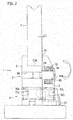
- the handle lever 54 of the operating device 5 is moved down as shown in FIG. 2 to swing the swinging body 3 about the first swinging fulcrum 4a to expand the channel mouth CM (to expand the clearance shown in the upper part in FIG. 2 ), and the press die P is inserted therein. That is, by the operation of the handle lever 54, the load of the elastic body 64 is turned about the first swinging fulcrum 4a in the clockwise direction in the drawing, until there are no lower clearances CL1 and CL2 in FIGS. 3 and 4 and the upper clearance CU shown in FIG. 2 is generated, thereby enabling the press die P to be detached and attached therefrom/thereto.
- the fulcrum shifts to the other swinging fulcrum (second swinging fulcrum) 4b of the swinging body 3 (at the upper part of the clamping point) correspondingly thereto, so that the clamping is completed.
- the lower clearance CL2 has the largest clearance amount adjusted by the adjustment screw 50b. Because the elastic body 64 is located on the upper side of the operation screw 52b, the upper part of the swinging body 3 works in a direction becoming close contact with the fixed support body 2.
- An opening amount at the time of expanding the channel mouth CM and a shift timing from the first swinging fulcrum 4a to the second swinging fulcrum 4b are adjusted by such adjustment that the adjustment screw 50b, whose turn is normally controlled by the screw member positioned at the lower part thereof, is turned by canceling the turning control with the screw member and the adjustment screw 50b is moved in the right and left directions in FIGS. 2 to 4 .
- the opening portion of the channel mouth CM is expanded by the operation of the handle lever 54 to hold the press die P in the channel mouth CM, and the handle lever 54 is then lifted upward to start to narrow down the opening portion of the channel mouth CM.
- the first swinging fulcrum 4a of the swinging body 3 is the swinging center around which the swinging body 3 swings in a direction of gradually narrowing down the channel mouth CM.
- a top part of the opening portion of the channel mouth CM becomes the second swinging fulcrum 4b, and the channel-mouth opening top, which is the second swinging fulcrum 4b of the swinging body 3, is clamped with a strongest force F at a position (the second switching fulcrum 4b) where the channel-mouth opening top abuts on the press die P to be clamped. That is, a unique clamping manner in which the fulcrum shifts to the second swinging fulcrum 4b at an upper part of a clamping point at the time of completion of the clamping operation is used and, in the principle of leverage, the fulcrum and the point of effort are located at the farthest positions from each other in the final form. Accordingly, the strongest clamping force F can be acquired with less power, whereby clamping is performed.
- the elastic body 64 that biases the channel mouth CM in the direction of reducing the size of the channel mouth CM is provided in the apparatus body 1 configured by the fixed support body 2 and the swinging body 3, on the side of the channel mouth CM. Accordingly, when swinging for the clamping progresses and the fulcrum shifts to the second swinging fulcrum 4b, the upper part of the clamping point can clamp the channel mouth CM more tightly due to biasing of the elastic body 64.
- a press die or the like can be set and fixed removably with a simple configuration and by a simple operation. Accordingly, as compared to the conventional clamp apparatus in which plural bolts need to be turned individually every time a press die or the like is attached or detached, higher workability can be provided and a replacement operation of a press die or the like can be performed within a short period of time. Therefore, even when the replacement is performed frequently, a high operation rate can be maintained and cost reduction can be achieved.
- clamp apparatus of the present invention is not limited only to the illustrated example and can be variously modified without departing from the scope of the present invention.
- the swinging body 3 is swingably supported by the bolt 66 as an example of the support member in the holding device 6.
- the elastic body 64 such as the disc spring is elastically installed between the bolt head 66a of the bolt 66 and the swinging body 3.
- the first swinging fulcrum 4a is provided in the swinging body 3 in a protruding manner between the tip of the swinging body 3 and the bolt 66, and the second swinging fulcrum 4b is provided at the tip of the swinging body 3 in a protruding manner.
- the first swinging fulcrum 4a and a shaft center of the bolt 66 as the support member are located eccentrically in a vertical direction.
- the first swinging fulcrum 4a is provided to be displaced with respect to the shaft center of the bolt 66 toward the tip side of the swinging body 3. Therefore, a biasing force (an accumulated energy force) of the elastic body 66 works in a direction of opening the tip side of the swinging body 3, using the first swinging fulcrum 4a as the fulcrum.
- the second swinging fulcrum 4b provided at the tip of the swinging body 3 is naturally separated from the press die P. This eliminates the need of an operation of separating the swinging body 3 from the press die P at the time of detaching the press die P. That is, efficiency in detachment of the press die P is improved.
- the swinging body 3 is swung using the second swinging fulcrum 4b at the tip as the fulcrum and tightens the press die P strongly.
- the energy storing force of the compressed elastic body 64 also works as a force tightening the press die P.
- the clamp apparatus according to the present invention is not limited to a clamp apparatus for a mold or the like, and the present invention can be also applied to any clamp apparatus that fixes an object.
Landscapes
- Engineering & Computer Science (AREA)
- Mechanical Engineering (AREA)
- General Engineering & Computer Science (AREA)
- Mounting, Exchange, And Manufacturing Of Dies (AREA)
- Bending Of Plates, Rods, And Pipes (AREA)
- Clamps And Clips (AREA)
Abstract
Description
- The present invention relates to a clamp apparatus used for removably clamping a clamping target object, for example, a press die including a punch (an upper die) and a die (a lower die), which is used in a bending machine such as a press brake that bends a sheet metal or the like.
- In order to removably set and fix a press die such as a punch (an upper die) and a die (a lower die), a clamp apparatus for a mold as described in
Patent Literature 1 listed below is used as an apparatus for setting this kind of die, in which a vertical die abutting surface that can abut on one side surface of a die is provided in a holder body that supports the die, and a clamping plate facing the die abutting surface and abutting on the other side surface of the die is attached to the holder body via a clamping tool (for example, see Patent Literature 1). - Patent Literature 1: Japanese Patent Application Laid-open No.
2002-219517 - However, in such a conventional clamp apparatus for mold, every time a die is attached or detached, a plurality of bolts need to be turned individually, which deteriorates the workability. Further, because a time is required for replacing a die, the operation rate decreases in case die replacement is performed frequently.
- Furthermore, a configuration that enables to obtain a tighter clamping force with less power has been desired.
- The present invention has been achieved in view of such circumstances, and an object of the present invention is to provide a clamp apparatus that can removably set and fix a fixing target object such as a press die with a simple structure and by a simple operation, and can provide a large clamping force by less power.
- In order to solve the above problems and to achieve the above object, a first aspect of the present invention provides a clamp apparatus in which a clamp portion is a channel mouth in cross-section and that performs clamping while, with respect to one fixed support body, other swinging body swings to narrow down an opening portion of the channel mouth in the clamp portion, wherein the clamp apparatus comprises two swinging fulcrums on a side of the swinging body; the swinging body swings about a first swinging fulcrum of the two swinging fulcrums at a time of opening the channel mouth and at an initial stage to start clamping of the channel mouth; and, as the swinging body swinging for the clamping progresses, the swinging body swings shiftedly about other swinging fulcrum of the two swinging fulcrums being a second swinging fulcrum located at an upper part of a clamping point, to complete clamping.
- According to the configuration described above, in order to clamp an object to be fixed, the opening portion of the channel mouth is expanded to put the object into the channel mouth, and narrowing of the opening portion of the channel mouth is then started. Until that time, the clamp apparatus swings about the first swinging fulcrum of the swinging body on a side facing the fixed support body. As swinging for the clamping progresses, the clamp apparatus shifts to the second swinging fulcrum at an upper part of a clamping point, to complete clamping. At this time, the top of the opening portion of the channel mouth becomes the second swinging fulcrum, and the object is clamped with the strongest force at a position where the top of the opening portion of the channel mouth, which is a swinging fulcrum of the swinging body, abuts on the object to be clamped.
- According to a second aspect of the present invention, in the clamp apparatus specified in the first aspect of the present invention, an elastic body that biases the swinging body in a direction of reducing a size of the channel mouth is provided in an apparatus body configured by the fixed support body and the swinging body, on a side of the channel mouth of the clamp apparatus; and, when swinging for clamping progresses and a fulcrum is shifted to the second swinging fulcrum at the upper part of the clamping point, the clamping becomes tighter due to biasing of the elastic body at the upper part of the clamping point.
- According to the configuration of the present invention described above, the following remarkable effect can be achieved. In order to clamp an object to be fixed, the opening portion of the channel mouth is expanded to put the object into the channel mouth, and narrowing of the opening portion of the channel mouth is then started. Until that time, the clamp apparatus swings about the first swinging fulcrum of the swinging body on a side facing the fixed support body. As swinging for the clamping progresses, the clamp apparatus shifts to the second swinging fulcrum at an upper part of a clamping point, to complete clamping. At the time of completion of the clamping, the top of the opening portion of the channel mouth becomes the second swinging fulcrum, thereby enabling the object to be clamped with the strongest force at a position where the top of the opening portion of the channel mouth, which is the swinging fulcrum of the swinging body, abuts on the object to be clamped.
- Furthermore, as described above, in the case of a configuration in which an apparatus body configured by a fixed support body and a swinging body on the channel mouth side of the clamp apparatus includes an elastic body that biases the channel mouth in a direction of narrowing down the channel mouth, when swinging for clamping progresses and a fulcrum shifts to the second swinging fulcrum at an upper part of a clamping point, tighter clamping can be achieved by biasing of the elastic body at the upper part of the clamping point.
- Therefore, an object to be fixed such as a press die can be set and fixed removably with a simple configuration and by a simple operation. Therefore, as compared to the conventional clamp apparatus in which plural bolts need to be turned individually every time an object to be fixed is attached or detached, higher workability can be provided and also a replacement operation of a press die or the like can be performed within a short period of time. Therefore, even when the replacement is performed frequently, a high operation rate can be maintained and cost reduction can be achieved.
- Further, a unique clamping manner in which there are two swinging fulcrums and at the last stage of clamping, the fulcrum shifts to the second swinging fulcrum at the upper part of the clamping point is used, and in the principle of leverage, the fulcrum and the point of effort are located at the farthest positions from each other in the final form. Accordingly, the strongest clamping force can be acquired with less power, whereby clamping is performed. This is the greatest characteristic of the present invention.
-
- [
FIG. 1] FIG. 1(a) is a sectional side view showing a configuration according to one embodiment of the present invention, and -
FIG. 1(b) is a front view showing the configuration according to the embodiment. - [
FIG. 2] FIG. 2 is a sectional view of a clamp apparatus, showing a state where a channel mouth CM is opened to insert a press die P in the configuration of the embodiment. - [
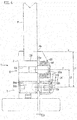
FIG. 3] FIG. 3 is a sectional view of the clamp apparatus, showing a state in the middle of operating a handle lever to perform clamping at the channel mouth CM of the press die P in the configuration of the embodiment. - [
FIG. 4] FIG. 4 is a sectional view of the clamp apparatus, showing a state where the handle lever is further operated and the clamping at the channel mouth CM of the press die P is completed in the configuration of the embodiment. - An embodiment of the present invention is explained below with reference to an illustrated example.
FIG. 1(a) to FIG. 4 show a configuration of a clamp apparatus according to an embodiment of the present invention, which is used at the time of bending, such as a press brake that bends a sheet metal or the like. The clamp apparatus removably sets and fixes a press die P such as a punch (an upper die) and a die (a lower die), to be held in a channel mouth CM in upper-part cross-section, which is formed between afixed support body 2 and a swingingbody 3 provided in anapparatus body 1 and which forms an opening (the channel mouth CM is provided by recessedly forming a channel that is open on the side of the swingingbody 3 at an upper part of thefixed support body 2 in a laterally longitudinal direction of theapparatus body 1 as shown inFIG. 1(b) ). - Specifically, the clamp apparatus includes the
fixed support body 2 provided in theapparatus body 1, the swingingbody 3 provided so as to be capable of swinging in a clamping direction with respect to thefixed support body 2 about a first swingingfulcrum 4a so as to clamp the press die P (at the last stage of the clamp operation, the swinging fulcrum shifts from the first swingingfulcrum 4a to a second swingingfulcrum 4b) that abuts on a surface of thefixed support body 2 facing thereto, and anoperating device 5 that performs opening of the channel mouth CM and clamping of the channel mouth CM by operating ahandle lever 54 provided on a lower side of theapparatus body 1 configured by thefixed support body 2 and the swingingbody 3. - The
operating device 5 is configured byspiral holes apparatus body 1 configured by thefixed support body 2 and the swingingbody 3, anadjustment screw 50b and anoperation screw 52b threaded into thespiral holes handle lever 54 attached on the side of theoperation screw 52b. Theoperating device 5 performs an operation to open the channel mouth CM and another operation of clamping at the channel mouth CM by operating thehandle lever 54. By adjusting an amount of protrusion or an amount of dent from thespiral hole 50a, theadjustment screw 50b adjusts an amount of swinging of the swinging operation of the swinging body 3 (an amount of a clearance CU indicated in an upper part ofFIG. 2 , an amount of a clearance CL1 indicated in a lower part ofFIG. 3 , and an amount of a clearance CL2 indicated in a lower part ofFIG. 4 ) between the amount of protrusion and the amount of dent of theoperation screw 52b from thespiral hole 52a by a turning action of the handle lever 54 (performs adjustment of the amount of swinging of theswinging body 3 in a clockwise direction and a counterclockwise direction inFIGS. 2 to 4 ). - In the present embodiment, the
apparatus body 1 also includes aholding device 6 that crimps thefixed support body 2 and the swingingbody 3 with an elastic force by using anelastic body 64 and abolt 66, on a side close to the channel mouth CM of theapparatus body 1, That is, theholding device 6 includes ascrew hole 60 on a side of thefixed support body 2 and a head buriedport 62 that houses abolt head 66a therein on a side of the swingingbody 3. Thescrew hole 60 and the head buriedport 62 are drilled substantially in parallel to thespiral holes adjustment screw 50b, and theoperation screw 52b. Theelastic body 64 configured by a spring member such as a spring or a disc spring is embedded on a side of the head buriedport 62. By causing thebolt 66 to pass through the center of theelastic body 64 to be threaded into thescrew hole 60, thefixed support body 2 and the swingingbody 3 are crimped with the elastic force while reducing the size of theelastic body 64 with thebolt head 66a. Accordingly, theelastic body 64 of theholding device 6 biases the channel mouth CM in a direction of reducing the size of the channel mouth CM. At this time, theholding device 6 does not completely fix the swingingbody 3 to thefixed support body 2 but merely crimps the swingingbody 3 thereto with the elastic force. Therefore, theelastic body 64 is set according to the tightening of thebolt 66 so as to obtain a specified load. - In the configuration described above, the swinging
body 3 includes two swinging fulcrums of the first and second swingingfulcrums fixed support body 2 facing thereto. At the time of opening the channel mouth CM, thehandle lever 54 of theoperating device 5 is moved down as shown inFIG. 2 to swing theswinging body 3 about the first swingingfulcrum 4a to expand the channel mouth CM (to expand the clearance shown in the upper part inFIG. 2 ), and the press die P is inserted therein. That is, by the operation of thehandle lever 54, the load of theelastic body 64 is turned about the first swingingfulcrum 4a in the clockwise direction in the drawing, until there are no lower clearances CL1 and CL2 inFIGS. 3 and4 and the upper clearance CU shown inFIG. 2 is generated, thereby enabling the press die P to be detached and attached therefrom/thereto. - To put the press die P into the channel mouth CM, clamping of the channel mouth CM is started while the
handle lever 54 is lifted up as shown inFIG. 3 . Also at an initial stage to start clamping, the swingingbody 3 swings about the first swingingfulcrum 4a. At this time, the upper clearance CU in the upper part ofFIG. 2 disappears and the clearance CL1 starts to open on a lower side as shown inFIG. 3 . That is, when theoperation screw 52b is screwed into thespiral hole 52a by moving the handle lever 54 upward, the lower clearances CL1 and CL2 (seeFIGS. 3 and4 ) of theswinging body 3 expand. - Specifically, when the
handle lever 54 is lifted up, theoperation screw 52b fixed to thehandle lever 54 is turned. At this time, a spherical member provided in a protruding manner on the left side of theoperation screw 52b (in the left direction inFIGS. 2 to 4 ) turns in a spherical space formed in theadjustment screw 50b in a concave shape as a spherical bearing unit. Because theadjustment screw 50b is fixed to thefixed support body 2, the lower part of the swingingbody 3 moves rightward (in the right direction inFIGS. 3 and4 ) due to the lead of a threaded portion between thespiral hole 52a and theoperation screw 52b when theoperation screw 52b turns. Accordingly, the swingingbody 3 swings in the counterclockwise direction inFIG. 3 about the first swingingfulcrum 4a and the clearance CL1 starts to open on the lower side as shown inFIG. 3 . - Meanwhile, when the handle lever 54 of the
operating device 5 is fully pulled down and swinging for clamping the press die P progresses as shown inFIG. 4 , the fulcrum shifts to the other swinging fulcrum (second swinging fulcrum) 4b of the swinging body 3 (at the upper part of the clamping point) correspondingly thereto, so that the clamping is completed. At this time, as shown inFIG. 4 , the lower clearance CL2 has the largest clearance amount adjusted by theadjustment screw 50b. Because theelastic body 64 is located on the upper side of theoperation screw 52b, the upper part of the swingingbody 3 works in a direction becoming close contact with the fixedsupport body 2. If theoperation screw 52b turns by more than a certain amount, an upper end of the swingingbody 3, that is, thesecond swinging fulcrum 4b becomes close contact with the press die P, and the press die P is reliably clamped by the fixedsupport body 2 and the swingingbody 3 due to an action of a tightening force F=(f×L2)/L1. An opening amount at the time of expanding the channel mouth CM and a shift timing from the first swingingfulcrum 4a to thesecond swinging fulcrum 4b are adjusted by such adjustment that theadjustment screw 50b, whose turn is normally controlled by the screw member positioned at the lower part thereof, is turned by canceling the turning control with the screw member and theadjustment screw 50b is moved in the right and left directions inFIGS. 2 to 4 . - As described above, in order to clamp the press die P to be fixed, the opening portion of the channel mouth CM is expanded by the operation of the
handle lever 54 to hold the press die P in the channel mouth CM, and thehandle lever 54 is then lifted upward to start to narrow down the opening portion of the channel mouth CM. Until that time, the first swingingfulcrum 4a of the swingingbody 3 is the swinging center around which the swingingbody 3 swings in a direction of gradually narrowing down the channel mouth CM. - Subsequently, as swinging for clamping the press die P progresses, the fulcrum shifts to the
second swinging fulcrum 4b to complete clamping. - At this time, a top part of the opening portion of the channel mouth CM becomes the
second swinging fulcrum 4b, and the channel-mouth opening top, which is thesecond swinging fulcrum 4b of the swingingbody 3, is clamped with a strongest force F at a position (thesecond switching fulcrum 4b) where the channel-mouth opening top abuts on the press die P to be clamped. That is, a unique clamping manner in which the fulcrum shifts to thesecond swinging fulcrum 4b at an upper part of a clamping point at the time of completion of the clamping operation is used and, in the principle of leverage, the fulcrum and the point of effort are located at the farthest positions from each other in the final form. Accordingly, the strongest clamping force F can be acquired with less power, whereby clamping is performed. - Furthermore, in the present embodiment, in addition to the configuration described above, the
elastic body 64 that biases the channel mouth CM in the direction of reducing the size of the channel mouth CM is provided in theapparatus body 1 configured by the fixedsupport body 2 and the swingingbody 3, on the side of the channel mouth CM. Accordingly, when swinging for the clamping progresses and the fulcrum shifts to thesecond swinging fulcrum 4b, the upper part of the clamping point can clamp the channel mouth CM more tightly due to biasing of theelastic body 64. - Therefore, according to the configuration of the present embodiment, a press die or the like can be set and fixed removably with a simple configuration and by a simple operation. Accordingly, as compared to the conventional clamp apparatus in which plural bolts need to be turned individually every time a press die or the like is attached or detached, higher workability can be provided and a replacement operation of a press die or the like can be performed within a short period of time. Therefore, even when the replacement is performed frequently, a high operation rate can be maintained and cost reduction can be achieved.
- The invention achieved by the present inventors has been described specifically based on the embodiment described above. However, the clamp apparatus of the present invention is not limited only to the illustrated example and can be variously modified without departing from the scope of the present invention.
- As can be understood from the descriptions of the embodiment described above and illustrations of
FIGS. 2 to 4 , according to the present embodiment, the swingingbody 3 is swingably supported by thebolt 66 as an example of the support member in theholding device 6. Theelastic body 64 such as the disc spring is elastically installed between thebolt head 66a of thebolt 66 and the swingingbody 3. Thefirst swinging fulcrum 4a is provided in the swingingbody 3 in a protruding manner between the tip of the swingingbody 3 and thebolt 66, and thesecond swinging fulcrum 4b is provided at the tip of the swingingbody 3 in a protruding manner. - That is, the first swinging
fulcrum 4a and a shaft center of thebolt 66 as the support member are located eccentrically in a vertical direction. In retrospect, the first swingingfulcrum 4a is provided to be displaced with respect to the shaft center of thebolt 66 toward the tip side of the swingingbody 3. Therefore, a biasing force (an accumulated energy force) of theelastic body 66 works in a direction of opening the tip side of the swingingbody 3, using the first swingingfulcrum 4a as the fulcrum. Accordingly, when clamping of the press die P is released, thesecond swinging fulcrum 4b provided at the tip of the swingingbody 3 is naturally separated from the press die P. This eliminates the need of an operation of separating the swingingbody 3 from the press die P at the time of detaching the press die P. That is, efficiency in detachment of the press die P is improved. - In the configuration described above, when the press die P is to be strongly tightened and fixed (pressed and fixed) to the side of the fixed
support body 2 at thesecond swinging fulcrum 4b at the tip of the swingingbody 3 by operating thehandle lever 54, the swingingbody 3 swings in the counterclockwise direction inFIGS. 2 to 4 in the initial state, using the first swingingfulcrum 4a as the fulcrum. When thehandle lever 54 is turned further in the same direction to tighten and fix the press die P more strongly after thesecond swinging fulcrum 4b at the tip abuts on the press die P, the first swingingfulcrum 4a of the swingingbody 3 tends to be away from the fixedsupport body 2, and theelastic body 64 is strongly compressed. That is, the swingingbody 3 is swung using thesecond swinging fulcrum 4b at the tip as the fulcrum and tightens the press die P strongly. At this time, the energy storing force of the compressedelastic body 64 also works as a force tightening the press die P. - The entire contents of Japanese Patent Application No.
2014-115326 (filed on June 3, 2014 - The clamp apparatus according to the present invention is not limited to a clamp apparatus for a mold or the like, and the present invention can be also applied to any clamp apparatus that fixes an object.
Claims (2)
- A clamp apparatus in which a clamp portion is a channel mouth in cross-section and that performs clamping while, with respect to one fixed support body, other swinging body swings to narrow down an opening portion of the channel mouth in the clamp portion, wherein
the clamp apparatus comprises two swinging fulcrums on a side of the swinging body;
the swinging body swings about a first swinging fulcrum of the two swinging fulcrums at a time of opening the channel mouth and at an initial stage to start clamping of the channel mouth; and
as the swinging body swinging for the clamping progresses, the swinging body swings shiftedly about other swinging fulcrum of the two swinging fulcrums being a second swinging fulcrum located at an upper part of a clamping point, to complete clamping. - The clamp apparatus according to claim 1, wherein
an elastic body that biases the swinging body in a direction of reducing a size of the channel mouth is provided in an apparatus body configured by the fixed support body and the swinging body, on a side of the channel mouth of the clamp apparatus; and
when swinging for clamping progresses and a fulcrum is shifted to the second swinging fulcrum at the upper part of the clamping point, the clamping becomes tighter due to biasing of the elastic body at the upper part of the clamping point.
Applications Claiming Priority (2)
| Application Number | Priority Date | Filing Date | Title |
|---|---|---|---|
| JP2014115326 | 2014-06-03 | ||
| PCT/JP2015/065918 WO2015186706A1 (en) | 2014-06-03 | 2015-06-02 | Clamp apparatus |
Publications (3)
| Publication Number | Publication Date |
|---|---|
| EP3153714A1 true EP3153714A1 (en) | 2017-04-12 |
| EP3153714A4 EP3153714A4 (en) | 2018-04-04 |
| EP3153714B1 EP3153714B1 (en) | 2021-10-13 |
Family
ID=54766775
Family Applications (1)
| Application Number | Title | Priority Date | Filing Date |
|---|---|---|---|
| EP15803169.0A Active EP3153714B1 (en) | 2014-06-03 | 2015-06-02 | Clamp apparatus |
Country Status (5)
| Country | Link |
|---|---|
| US (1) | US10328480B2 (en) |
| EP (1) | EP3153714B1 (en) |
| JP (1) | JP6364483B2 (en) |
| CN (1) | CN106460893B (en) |
| WO (1) | WO2015186706A1 (en) |
Families Citing this family (3)
| Publication number | Priority date | Publication date | Assignee | Title |
|---|---|---|---|---|
| JP6697949B2 (en) * | 2016-05-17 | 2020-05-27 | 株式会社アマダ | Mold clamping device |
| DE202017101263U1 (en) * | 2017-03-06 | 2017-03-24 | Häfele GmbH & Co KG | Clamping connector and mounting arrangement |
| JP7570686B2 (en) | 2021-02-05 | 2024-10-22 | 株式会社 タガミ・イーエクス | Press brake lower die fixing device and press brake lower die fixing method |
Family Cites Families (14)
| Publication number | Priority date | Publication date | Assignee | Title |
|---|---|---|---|---|
| JP3274870B2 (en) * | 1991-07-15 | 2002-04-15 | 西丘化成有限会社 | Support structure of clamp bracket |
| JPH0813379B2 (en) | 1992-05-15 | 1996-02-14 | 株式会社アマダメトレックス | Mold holder for press brake |
| US5619885A (en) * | 1992-05-15 | 1997-04-15 | Amada Metrecs Company, Limited | Upper tool holder apparatus for press brake and method of holding the upper tool |
| TW249765B (en) * | 1993-05-18 | 1995-06-21 | Amatamedory Kk | |
| JP2921741B2 (en) * | 1995-10-02 | 1999-07-19 | 株式会社アマダメトレックス | Upper die holder device for press brake |
| JP3741496B2 (en) * | 1996-11-19 | 2006-02-01 | 株式会社小松製作所 | Press brake upper die mounting device |
| US6003360A (en) * | 1997-07-01 | 1999-12-21 | Wilson Tool International, Inc. | Press brake tool holder |
| JP3470046B2 (en) * | 1998-08-25 | 2003-11-25 | 株式会社アマダ | Upper die holder device for press brake |
| IT1309746B1 (en) * | 1999-04-07 | 2002-01-30 | Toolspress S R L | MODULAR ELEMENT FOR TOOL SUPPORT IN BENDING PLATE PRESSES. |
| JP3495335B2 (en) | 2001-01-22 | 2004-02-09 | 株式会社アマダ | Mold support device |
| FR2851488B1 (en) * | 2003-02-21 | 2005-05-20 | Amada Europ Sa | FIXING SYSTEM FOR MOUNTING AND DISASSEMBLING A FOLDING TOOL |
| US6848291B1 (en) * | 2004-02-13 | 2005-02-01 | Wilson Tool International, Inc. | Press brake tool and tool holder |
| JP5588819B2 (en) * | 2010-10-19 | 2014-09-10 | 株式会社アマダ | Upper mold holder device |
| JP5855909B2 (en) * | 2011-11-07 | 2016-02-09 | パスカルエンジニアリング株式会社 | Clamping device |
-
2015
- 2015-06-02 US US15/315,156 patent/US10328480B2/en active Active
- 2015-06-02 WO PCT/JP2015/065918 patent/WO2015186706A1/en not_active Ceased
- 2015-06-02 CN CN201580029741.5A patent/CN106460893B/en active Active
- 2015-06-02 JP JP2016525187A patent/JP6364483B2/en active Active
- 2015-06-02 EP EP15803169.0A patent/EP3153714B1/en active Active
Also Published As
| Publication number | Publication date |
|---|---|
| US20170182542A1 (en) | 2017-06-29 |
| CN106460893B (en) | 2018-11-02 |
| JPWO2015186706A1 (en) | 2017-04-20 |
| EP3153714A4 (en) | 2018-04-04 |
| JP6364483B2 (en) | 2018-07-25 |
| US10328480B2 (en) | 2019-06-25 |
| WO2015186706A1 (en) | 2015-12-10 |
| CN106460893A (en) | 2017-02-22 |
| EP3153714B1 (en) | 2021-10-13 |
Similar Documents
| Publication | Publication Date | Title |
|---|---|---|
| EP3153714B1 (en) | Clamp apparatus | |
| JP5789038B1 (en) | Electric wire connector | |
| WO2007100907A3 (en) | Tool holder assembly | |
| KR100307922B1 (en) | Upper tool holding apparatus and upper tool separating method from upper tool holding apparatus | |
| US10512960B2 (en) | Extrusion press | |
| WO2009008483A1 (en) | Scrap shearing machine | |
| MX2020005568A (en) | Crimping pliers. | |
| CN110125237A (en) | Stamping die is used in the blade clearance experiment of Quick-change punch | |
| JP2008264981A (en) | Toggle type hand | |
| US8578751B2 (en) | Tool with different effective areas | |
| WO2002064278A1 (en) | Cope holder device | |
| US7284330B2 (en) | Cutting device for workpieces such as rods, bolts and the like, especially for threaded rods | |
| JP2013103327A (en) | Vise | |
| US7331736B2 (en) | Metal cutting tool | |
| JP2009284722A (en) | Wire covering stripping tool | |
| CN201744555U (en) | Blanking die combined mechanism | |
| CN102303231B (en) | Screw stud installation mechanism of automatic screw stud riveting machine | |
| JP2018187648A (en) | Die fitting device | |
| CN202539981U (en) | Clamp for fixing spring hook blank | |
| KR101925622B1 (en) | Operating tool for pipe connecting device | |
| JP2009101412A (en) | Weir-folding method for separating cast products and scrap materials from the plan, and the weir-folding device | |
| CN103372748A (en) | Fast clamping electric soldering tweezers | |
| JP2014114565A (en) | Slide part clearance adjustment mechanism | |
| JP2008311035A (en) | Method of holding external thread, fittings with terminal screw, terminal board device, method of manufacturing fittings with terminal screw, and device for manufacturing fittings with terminal screw | |
| CN201979412U (en) | Circular-jaw locking plier |
Legal Events
| Date | Code | Title | Description |
|---|---|---|---|
| STAA | Information on the status of an ep patent application or granted ep patent |
Free format text: STATUS: THE INTERNATIONAL PUBLICATION HAS BEEN MADE |
|
| PUAI | Public reference made under article 153(3) epc to a published international application that has entered the european phase |
Free format text: ORIGINAL CODE: 0009012 |
|
| STAA | Information on the status of an ep patent application or granted ep patent |
Free format text: STATUS: REQUEST FOR EXAMINATION WAS MADE |
|
| 17P | Request for examination filed |
Effective date: 20161229 |
|
| AK | Designated contracting states |
Kind code of ref document: A1 Designated state(s): AL AT BE BG CH CY CZ DE DK EE ES FI FR GB GR HR HU IE IS IT LI LT LU LV MC MK MT NL NO PL PT RO RS SE SI SK SM TR |
|
| AX | Request for extension of the european patent |
Extension state: BA ME |
|
| DAV | Request for validation of the european patent (deleted) | ||
| DAX | Request for extension of the european patent (deleted) | ||
| REG | Reference to a national code |
Ref country code: DE Ref legal event code: R079 Ref document number: 602015074133 Country of ref document: DE Free format text: PREVIOUS MAIN CLASS: F16B0002100000 Ipc: B21D0005020000 |
|
| A4 | Supplementary search report drawn up and despatched |
Effective date: 20180305 |
|
| RIC1 | Information provided on ipc code assigned before grant |
Ipc: F16B 2/18 20060101ALI20180227BHEP Ipc: B21D 5/02 20060101AFI20180227BHEP |
|
| GRAP | Despatch of communication of intention to grant a patent |
Free format text: ORIGINAL CODE: EPIDOSNIGR1 |
|
| STAA | Information on the status of an ep patent application or granted ep patent |
Free format text: STATUS: GRANT OF PATENT IS INTENDED |
|
| INTG | Intention to grant announced |
Effective date: 20210526 |
|
| RAP3 | Party data changed (applicant data changed or rights of an application transferred) |
Owner name: AMADA HOLDINGS CO., LTD. |
|
| GRAS | Grant fee paid |
Free format text: ORIGINAL CODE: EPIDOSNIGR3 |
|
| GRAA | (expected) grant |
Free format text: ORIGINAL CODE: 0009210 |
|
| STAA | Information on the status of an ep patent application or granted ep patent |
Free format text: STATUS: THE PATENT HAS BEEN GRANTED |
|
| AK | Designated contracting states |
Kind code of ref document: B1 Designated state(s): AL AT BE BG CH CY CZ DE DK EE ES FI FR GB GR HR HU IE IS IT LI LT LU LV MC MK MT NL NO PL PT RO RS SE SI SK SM TR |
|
| REG | Reference to a national code |
Ref country code: GB Ref legal event code: FG4D |
|
| REG | Reference to a national code |
Ref country code: CH Ref legal event code: EP |
|
| REG | Reference to a national code |
Ref country code: DE Ref legal event code: R096 Ref document number: 602015074133 Country of ref document: DE |
|
| REG | Reference to a national code |
Ref country code: IE Ref legal event code: FG4D |
|
| REG | Reference to a national code |
Ref country code: AT Ref legal event code: REF Ref document number: 1437792 Country of ref document: AT Kind code of ref document: T Effective date: 20211115 |
|
| REG | Reference to a national code |
Ref country code: LT Ref legal event code: MG9D |
|
| REG | Reference to a national code |
Ref country code: NL Ref legal event code: MP Effective date: 20211013 |
|
| REG | Reference to a national code |
Ref country code: AT Ref legal event code: MK05 Ref document number: 1437792 Country of ref document: AT Kind code of ref document: T Effective date: 20211013 |
|
| PG25 | Lapsed in a contracting state [announced via postgrant information from national office to epo] |
Ref country code: RS Free format text: LAPSE BECAUSE OF FAILURE TO SUBMIT A TRANSLATION OF THE DESCRIPTION OR TO PAY THE FEE WITHIN THE PRESCRIBED TIME-LIMIT Effective date: 20211013 Ref country code: LT Free format text: LAPSE BECAUSE OF FAILURE TO SUBMIT A TRANSLATION OF THE DESCRIPTION OR TO PAY THE FEE WITHIN THE PRESCRIBED TIME-LIMIT Effective date: 20211013 Ref country code: FI Free format text: LAPSE BECAUSE OF FAILURE TO SUBMIT A TRANSLATION OF THE DESCRIPTION OR TO PAY THE FEE WITHIN THE PRESCRIBED TIME-LIMIT Effective date: 20211013 Ref country code: BG Free format text: LAPSE BECAUSE OF FAILURE TO SUBMIT A TRANSLATION OF THE DESCRIPTION OR TO PAY THE FEE WITHIN THE PRESCRIBED TIME-LIMIT Effective date: 20220113 Ref country code: AT Free format text: LAPSE BECAUSE OF FAILURE TO SUBMIT A TRANSLATION OF THE DESCRIPTION OR TO PAY THE FEE WITHIN THE PRESCRIBED TIME-LIMIT Effective date: 20211013 |
|
| PG25 | Lapsed in a contracting state [announced via postgrant information from national office to epo] |
Ref country code: IS Free format text: LAPSE BECAUSE OF FAILURE TO SUBMIT A TRANSLATION OF THE DESCRIPTION OR TO PAY THE FEE WITHIN THE PRESCRIBED TIME-LIMIT Effective date: 20220213 Ref country code: SE Free format text: LAPSE BECAUSE OF FAILURE TO SUBMIT A TRANSLATION OF THE DESCRIPTION OR TO PAY THE FEE WITHIN THE PRESCRIBED TIME-LIMIT Effective date: 20211013 Ref country code: PT Free format text: LAPSE BECAUSE OF FAILURE TO SUBMIT A TRANSLATION OF THE DESCRIPTION OR TO PAY THE FEE WITHIN THE PRESCRIBED TIME-LIMIT Effective date: 20220214 Ref country code: PL Free format text: LAPSE BECAUSE OF FAILURE TO SUBMIT A TRANSLATION OF THE DESCRIPTION OR TO PAY THE FEE WITHIN THE PRESCRIBED TIME-LIMIT Effective date: 20211013 Ref country code: NO Free format text: LAPSE BECAUSE OF FAILURE TO SUBMIT A TRANSLATION OF THE DESCRIPTION OR TO PAY THE FEE WITHIN THE PRESCRIBED TIME-LIMIT Effective date: 20220113 Ref country code: NL Free format text: LAPSE BECAUSE OF FAILURE TO SUBMIT A TRANSLATION OF THE DESCRIPTION OR TO PAY THE FEE WITHIN THE PRESCRIBED TIME-LIMIT Effective date: 20211013 Ref country code: LV Free format text: LAPSE BECAUSE OF FAILURE TO SUBMIT A TRANSLATION OF THE DESCRIPTION OR TO PAY THE FEE WITHIN THE PRESCRIBED TIME-LIMIT Effective date: 20211013 Ref country code: HR Free format text: LAPSE BECAUSE OF FAILURE TO SUBMIT A TRANSLATION OF THE DESCRIPTION OR TO PAY THE FEE WITHIN THE PRESCRIBED TIME-LIMIT Effective date: 20211013 Ref country code: GR Free format text: LAPSE BECAUSE OF FAILURE TO SUBMIT A TRANSLATION OF THE DESCRIPTION OR TO PAY THE FEE WITHIN THE PRESCRIBED TIME-LIMIT Effective date: 20220114 Ref country code: ES Free format text: LAPSE BECAUSE OF FAILURE TO SUBMIT A TRANSLATION OF THE DESCRIPTION OR TO PAY THE FEE WITHIN THE PRESCRIBED TIME-LIMIT Effective date: 20211013 |
|
| REG | Reference to a national code |
Ref country code: DE Ref legal event code: R097 Ref document number: 602015074133 Country of ref document: DE |
|
| PG25 | Lapsed in a contracting state [announced via postgrant information from national office to epo] |
Ref country code: SM Free format text: LAPSE BECAUSE OF FAILURE TO SUBMIT A TRANSLATION OF THE DESCRIPTION OR TO PAY THE FEE WITHIN THE PRESCRIBED TIME-LIMIT Effective date: 20211013 Ref country code: SK Free format text: LAPSE BECAUSE OF FAILURE TO SUBMIT A TRANSLATION OF THE DESCRIPTION OR TO PAY THE FEE WITHIN THE PRESCRIBED TIME-LIMIT Effective date: 20211013 Ref country code: RO Free format text: LAPSE BECAUSE OF FAILURE TO SUBMIT A TRANSLATION OF THE DESCRIPTION OR TO PAY THE FEE WITHIN THE PRESCRIBED TIME-LIMIT Effective date: 20211013 Ref country code: EE Free format text: LAPSE BECAUSE OF FAILURE TO SUBMIT A TRANSLATION OF THE DESCRIPTION OR TO PAY THE FEE WITHIN THE PRESCRIBED TIME-LIMIT Effective date: 20211013 Ref country code: DK Free format text: LAPSE BECAUSE OF FAILURE TO SUBMIT A TRANSLATION OF THE DESCRIPTION OR TO PAY THE FEE WITHIN THE PRESCRIBED TIME-LIMIT Effective date: 20211013 Ref country code: CZ Free format text: LAPSE BECAUSE OF FAILURE TO SUBMIT A TRANSLATION OF THE DESCRIPTION OR TO PAY THE FEE WITHIN THE PRESCRIBED TIME-LIMIT Effective date: 20211013 |
|
| PLBE | No opposition filed within time limit |
Free format text: ORIGINAL CODE: 0009261 |
|
| STAA | Information on the status of an ep patent application or granted ep patent |
Free format text: STATUS: NO OPPOSITION FILED WITHIN TIME LIMIT |
|
| 26N | No opposition filed |
Effective date: 20220714 |
|
| PG25 | Lapsed in a contracting state [announced via postgrant information from national office to epo] |
Ref country code: AL Free format text: LAPSE BECAUSE OF FAILURE TO SUBMIT A TRANSLATION OF THE DESCRIPTION OR TO PAY THE FEE WITHIN THE PRESCRIBED TIME-LIMIT Effective date: 20211013 |
|
| PG25 | Lapsed in a contracting state [announced via postgrant information from national office to epo] |
Ref country code: SI Free format text: LAPSE BECAUSE OF FAILURE TO SUBMIT A TRANSLATION OF THE DESCRIPTION OR TO PAY THE FEE WITHIN THE PRESCRIBED TIME-LIMIT Effective date: 20211013 |
|
| PG25 | Lapsed in a contracting state [announced via postgrant information from national office to epo] |
Ref country code: MC Free format text: LAPSE BECAUSE OF FAILURE TO SUBMIT A TRANSLATION OF THE DESCRIPTION OR TO PAY THE FEE WITHIN THE PRESCRIBED TIME-LIMIT Effective date: 20211013 |
|
| REG | Reference to a national code |
Ref country code: CH Ref legal event code: PL |
|
| REG | Reference to a national code |
Ref country code: BE Ref legal event code: MM Effective date: 20220630 |
|
| GBPC | Gb: european patent ceased through non-payment of renewal fee |
Effective date: 20220602 |
|
| PG25 | Lapsed in a contracting state [announced via postgrant information from national office to epo] |
Ref country code: LU Free format text: LAPSE BECAUSE OF NON-PAYMENT OF DUE FEES Effective date: 20220602 Ref country code: LI Free format text: LAPSE BECAUSE OF NON-PAYMENT OF DUE FEES Effective date: 20220630 Ref country code: IE Free format text: LAPSE BECAUSE OF NON-PAYMENT OF DUE FEES Effective date: 20220602 Ref country code: CH Free format text: LAPSE BECAUSE OF NON-PAYMENT OF DUE FEES Effective date: 20220630 |
|
| PG25 | Lapsed in a contracting state [announced via postgrant information from national office to epo] |
Ref country code: IT Free format text: LAPSE BECAUSE OF FAILURE TO SUBMIT A TRANSLATION OF THE DESCRIPTION OR TO PAY THE FEE WITHIN THE PRESCRIBED TIME-LIMIT Effective date: 20211013 Ref country code: GB Free format text: LAPSE BECAUSE OF NON-PAYMENT OF DUE FEES Effective date: 20220602 Ref country code: BE Free format text: LAPSE BECAUSE OF NON-PAYMENT OF DUE FEES Effective date: 20220630 |
|
| P01 | Opt-out of the competence of the unified patent court (upc) registered |
Effective date: 20230428 |
|
| PG25 | Lapsed in a contracting state [announced via postgrant information from national office to epo] |
Ref country code: HU Free format text: LAPSE BECAUSE OF FAILURE TO SUBMIT A TRANSLATION OF THE DESCRIPTION OR TO PAY THE FEE WITHIN THE PRESCRIBED TIME-LIMIT; INVALID AB INITIO Effective date: 20150602 |
|
| PG25 | Lapsed in a contracting state [announced via postgrant information from national office to epo] |
Ref country code: MK Free format text: LAPSE BECAUSE OF FAILURE TO SUBMIT A TRANSLATION OF THE DESCRIPTION OR TO PAY THE FEE WITHIN THE PRESCRIBED TIME-LIMIT Effective date: 20211013 Ref country code: CY Free format text: LAPSE BECAUSE OF FAILURE TO SUBMIT A TRANSLATION OF THE DESCRIPTION OR TO PAY THE FEE WITHIN THE PRESCRIBED TIME-LIMIT Effective date: 20211013 |
|
| PGFP | Annual fee paid to national office [announced via postgrant information from national office to epo] |
Ref country code: FR Payment date: 20240628 Year of fee payment: 10 |
|
| PG25 | Lapsed in a contracting state [announced via postgrant information from national office to epo] |
Ref country code: MT Free format text: LAPSE BECAUSE OF FAILURE TO SUBMIT A TRANSLATION OF THE DESCRIPTION OR TO PAY THE FEE WITHIN THE PRESCRIBED TIME-LIMIT Effective date: 20211013 |
|
| PGFP | Annual fee paid to national office [announced via postgrant information from national office to epo] |
Ref country code: DE Payment date: 20250618 Year of fee payment: 11 |
|
| PG25 | Lapsed in a contracting state [announced via postgrant information from national office to epo] |
Ref country code: TR Free format text: LAPSE BECAUSE OF FAILURE TO SUBMIT A TRANSLATION OF THE DESCRIPTION OR TO PAY THE FEE WITHIN THE PRESCRIBED TIME-LIMIT Effective date: 20211013 |
|
| PG25 | Lapsed in a contracting state [announced via postgrant information from national office to epo] |
Ref country code: FR Free format text: LAPSE BECAUSE OF NON-PAYMENT OF DUE FEES Effective date: 20250630 |