EP3153285A1 - A rotary cutting apparatus with an embedded monitoring unit - Google Patents
A rotary cutting apparatus with an embedded monitoring unit Download PDFInfo
- Publication number
- EP3153285A1 EP3153285A1 EP15306573.5A EP15306573A EP3153285A1 EP 3153285 A1 EP3153285 A1 EP 3153285A1 EP 15306573 A EP15306573 A EP 15306573A EP 3153285 A1 EP3153285 A1 EP 3153285A1
- Authority
- EP
- European Patent Office
- Prior art keywords
- rotary
- monitoring unit
- working parameter
- cutting apparatus
- anvil
- Prior art date
- Legal status (The legal status is an assumption and is not a legal conclusion. Google has not performed a legal analysis and makes no representation as to the accuracy of the status listed.)
- Granted
Links
Images

Classifications
-
- B—PERFORMING OPERATIONS; TRANSPORTING
- B26—HAND CUTTING TOOLS; CUTTING; SEVERING
- B26D—CUTTING; DETAILS COMMON TO MACHINES FOR PERFORATING, PUNCHING, CUTTING-OUT, STAMPING-OUT OR SEVERING
- B26D7/00—Details of apparatus for cutting, cutting-out, stamping-out, punching, perforating, or severing by means other than cutting
- B26D7/27—Means for performing other operations combined with cutting
-
- B—PERFORMING OPERATIONS; TRANSPORTING
- B26—HAND CUTTING TOOLS; CUTTING; SEVERING
- B26D—CUTTING; DETAILS COMMON TO MACHINES FOR PERFORATING, PUNCHING, CUTTING-OUT, STAMPING-OUT OR SEVERING
- B26D1/00—Cutting through work characterised by the nature or movement of the cutting member or particular materials not otherwise provided for; Apparatus or machines therefor; Cutting members therefor
- B26D1/01—Cutting through work characterised by the nature or movement of the cutting member or particular materials not otherwise provided for; Apparatus or machines therefor; Cutting members therefor involving a cutting member which does not travel with the work
- B26D1/12—Cutting through work characterised by the nature or movement of the cutting member or particular materials not otherwise provided for; Apparatus or machines therefor; Cutting members therefor involving a cutting member which does not travel with the work having a cutting member moving about an axis
- B26D1/25—Cutting through work characterised by the nature or movement of the cutting member or particular materials not otherwise provided for; Apparatus or machines therefor; Cutting members therefor involving a cutting member which does not travel with the work having a cutting member moving about an axis with a non-circular cutting member
- B26D1/34—Cutting through work characterised by the nature or movement of the cutting member or particular materials not otherwise provided for; Apparatus or machines therefor; Cutting members therefor involving a cutting member which does not travel with the work having a cutting member moving about an axis with a non-circular cutting member moving about an axis parallel to the line of cut
- B26D1/40—Cutting through work characterised by the nature or movement of the cutting member or particular materials not otherwise provided for; Apparatus or machines therefor; Cutting members therefor involving a cutting member which does not travel with the work having a cutting member moving about an axis with a non-circular cutting member moving about an axis parallel to the line of cut and coacting with a rotary member
-
- B—PERFORMING OPERATIONS; TRANSPORTING
- B26—HAND CUTTING TOOLS; CUTTING; SEVERING
- B26D—CUTTING; DETAILS COMMON TO MACHINES FOR PERFORATING, PUNCHING, CUTTING-OUT, STAMPING-OUT OR SEVERING
- B26D5/00—Arrangements for operating and controlling machines or devices for cutting, cutting-out, stamping-out, punching, perforating, or severing by means other than cutting
-
- B—PERFORMING OPERATIONS; TRANSPORTING
- B26—HAND CUTTING TOOLS; CUTTING; SEVERING
- B26D—CUTTING; DETAILS COMMON TO MACHINES FOR PERFORATING, PUNCHING, CUTTING-OUT, STAMPING-OUT OR SEVERING
- B26D7/00—Details of apparatus for cutting, cutting-out, stamping-out, punching, perforating, or severing by means other than cutting
- B26D7/26—Means for mounting or adjusting the cutting member; Means for adjusting the stroke of the cutting member
-
- B—PERFORMING OPERATIONS; TRANSPORTING
- B26—HAND CUTTING TOOLS; CUTTING; SEVERING
- B26D—CUTTING; DETAILS COMMON TO MACHINES FOR PERFORATING, PUNCHING, CUTTING-OUT, STAMPING-OUT OR SEVERING
- B26D7/00—Details of apparatus for cutting, cutting-out, stamping-out, punching, perforating, or severing by means other than cutting
- B26D7/26—Means for mounting or adjusting the cutting member; Means for adjusting the stroke of the cutting member
- B26D7/2628—Means for adjusting the position of the cutting member
- B26D7/265—Journals, bearings or supports for positioning rollers or cylinders relatively to each other
-
- B—PERFORMING OPERATIONS; TRANSPORTING
- B26—HAND CUTTING TOOLS; CUTTING; SEVERING
- B26F—PERFORATING; PUNCHING; CUTTING-OUT; STAMPING-OUT; SEVERING BY MEANS OTHER THAN CUTTING
- B26F1/00—Perforating; Punching; Cutting-out; Stamping-out; Apparatus therefor
- B26F1/38—Cutting-out; Stamping-out
- B26F1/384—Cutting-out; Stamping-out using rotating drums
-
- B—PERFORMING OPERATIONS; TRANSPORTING
- B26—HAND CUTTING TOOLS; CUTTING; SEVERING
- B26F—PERFORATING; PUNCHING; CUTTING-OUT; STAMPING-OUT; SEVERING BY MEANS OTHER THAN CUTTING
- B26F1/00—Perforating; Punching; Cutting-out; Stamping-out; Apparatus therefor
- B26F1/38—Cutting-out; Stamping-out
Definitions
- the present disclosure relates to a rotary cutting apparatus comprising a monitoring unit (28) being at least partially embedded in at least one of the first and the second drums (37 or 38) of the first and the second rotary devices (14 or 16), the monitoring unit (28) being configured for measuring at least one working parameter and for transmitting data representative of the at least one working parameter between the monitoring unit (28) and an interface transmission unit positioned outside either the first or second rotary device or both.
- the present disclosure also relates to a method for transmitting data and energy.
- Rotary cutting apparatus is for example known from EP-A-2 508 311 .
- An aspect of the present disclosure is to provide an improved rotary cutting apparatus which will solve and/or reduce the problems mentioned above.
- the present disclosure therefore relates to a rotary cutting apparatus as defined in the permeable of claim 1 further comprising a monitoring unit at least partially embedded in at least one of the first or the second drums of the first and the second rotary devices, the monitoring unit being configured for measuring at least one working parameter and for transmitting data representative of the at least one working parameter between the monitoring unit and an interface transmission unit positioned outside either the first or second rotary device or both.
- a maintenance operation is needed and also what maintenance is needed to be performed, such as for example preventive maintenance.
- a preventive maintenance operation is for example cleaning, checking and adjusting the equipment.
- the monitoring unit which is at least partially embedded in at least one of the first and the second drums will obtain, while machining is performed, accurate measurements relating to the cutting operation, such as the number of produced workpiece and/or a temperature of a cutting edge.
- the position of the monitoring unit enables the disposition of sensing means very close to the external surface of the rotary device in which the monitoring unit is at least partially embedded thereby improving the accuracy of the measurements carried out in a remote position from the rotary devices and/or the cutting area.
- the monitoring unit may be at least partially embedded in both of the first and second drums of the first and the second rotary devices.
- the "cutting area” refers to a space closely surrounding the first and second rotary devices, particularly around a cutting edge provided onto the first or the second rotary device, when the rotary cutting apparatus is running.
- the at least one working parameter refers to a physical property or a dynamic behaviour or a state which is able to be measured or detected which relates to the cutting operation performed by the rotary cutting apparatus.
- the at least one working parameter may be a parameter related to the first and/or the second rotary device, the force means or any member of the rotary cutting apparatus participating to the cutting operation.
- the at least one working parameter may refer to any parameter which may be used to control the cutting operation.
- Data representative of the at least one working parameter refers to data determined from the measured and/or detected working parameter.
- a sensor measures a working parameter so as to output data representative of this working parameter.
- data representative of the working parameter also refers to data calculated according to the working parameter, for example calculating another parameter according to the working parameter or determining that a threshold value is reached. Examples, but not limiting, of what working parameters may be measured and/or detected are vibrations, dirtiness of the equipment and temperature.
- the monitoring unit allows a real-time control of the cutting operation. For example, it is possible to control the speed of rotation of the rotary devices and/or the feed speed of the workpiece.
- This real-time control will provide for the possibility to directly reacting and solving deviation within the operation by e.g. varying the process, operation and/or machining conditions according to the measured working parameters, thereby improving the productivity of the rotary cutting apparatus. Furthermore, by measuring working parameters related to the first and/or second rotary device itself, it is possible to know in real-time the activity of said rotary device so as to know when maintenance is needed and, particularly, what kind of maintenance is needed. For example, when said rotary cutting device should be replaced, sharpened or ground. Hence, real-time transmission of working parameters will allow more efficient scheduling of the maintenance. Thus, by combining monitored working parameters and performance data, the monitoring unit will enable insights on maintenance and performance data for optimizing productivity of the rotary cutting apparatus.
- the rotary cutting apparatus as defined hereinabove or hereinafter also comprises an interface transmission unit arranged onto the frame, wherein the monitoring unit is further configured for transmitting data through wireless transmission between the monitoring unit and the interface transmission unit.
- the monitoring unit is being configured for measuring one working parameter. According to another embodiment, the monitoring unit is being configured for measuring more than one working parameter.
- the monitoring unit as defined hereinabove or hereinafter is further configured for transmitting power energy through wireless transmission between the monitoring unit and the interface transmission unit.
- power energy refers to the energy needed to power the monitoring unit without the use of batteries. Thus, there will be no need to change batteries.
- the monitoring unit is configured for transmitting data together with power energy at a frequency between 1 and 25kHz (between 1 and 25 thousand cycles per second) and it will enable wireless transmission of both data and power energy while avoiding unsatisfactory losses, which will happen when the wireless transmission is performed at high frequency, i.e. above 1 MHz (1 million cycles per second).
- power energy at a frequency between 1 and 25kHz (between 1 and 25 thousand cycles per second) and it will enable wireless transmission of both data and power energy while avoiding unsatisfactory losses, which will happen when the wireless transmission is performed at high frequency, i.e. above 1 MHz (1 million cycles per second).
- magnetic fields used for wireless transmission may be absorbed by the metals used in the equipment. If the magnetic fields are absorbed, they will heat the equipment which will cause problems. Therefore, the correct power energy frequency must be carefully selected.
- each of the first and second pair of bearing housings comprises a stationary bearing housing coupled to the frame and a rotary bearing housing coupled to the first or the second shaft
- the monitoring unit comprises a rotary antenna coupled to a rotary bearing housing
- the interface transmission unit comprises a stationary antenna coupled to a stationary bearing housing of a same first or second pair of bearing housings, and wherein the interface transmission unit and the monitoring unit are configured for transmitting data and/or power energy between the stationary and the rotary antennas through wireless transmission.
- the monitoring unit comprises the at least one sensor for measuring at least one working parameter and outputting data representative of the at least one working parameter; a controller connected to the sensor for receiving data representative of the at least one working parameter, the controller being further configured for processing the data representative of the at least one working parameter and for transmitting the said data representative of the at least one working parameter to the interface transmission unit.
- the monitoring unit may comprise at least one sensor selected from the group of a temperature sensor, a vibration sensor, a load sensor and a rotation sensor.
- the controller may comprise a memory for storing data which has been obtained from the sensor and/or data transmitted by the interface transmission unit and a calculator connected to the memory for calculating a new parameter. Since rotary tools can be assembled and disassembled in the rotary cutting apparatus several times, a memory which is able to store data obtained from the sensor or data transmitted by the interface transmission unit will allow the recovery and/also the surveillance of the operational history of the rotary cutting device at any time.
- the at least one working parameter is selected from at least one of: a temperature at an external surface of the first and/or the second rotary devices, a temperature difference between the first and/or the second rotary devices, a vibration level of the first and/or the second rotary devices, a slippage between the first and the second rotary devices, the number of cuts performed by the first and/or the second rotary device(s) and the number of revolutions of the first and/or the second rotary device(s).
- the rotary cutting apparatus further comprises a display unit for displaying data transmitted by the monitoring unit.
- a method for transmitting data comprising the following steps: providing a rotary cutting apparatus as defined hereinabove or hereinafter; measuring at least one working parameter with the monitoring unit; processing the data representative of the at least one working parameter; and transmitting the processed data representative of the at least one working parameter from the monitoring unit to an interface transmission unit through wireless transmission.
- the method as defined hereinabove or hereinafter may further comprise the step of transmitting power energy from a power energy generator, positioned outside the first and/or the second rotary devices to the monitoring unit through wireless transmission.
- the steps of measuring at least one working parameter, processing the data representative of the at least one working parameter and transmitting data and/or power energy are performed while the first and/or the second rotary devices is rotated.
- one working parameter is measured.
- more than one working parameter is measured.
- Figures 1 and 2 show a rotary cutting apparatus 10 comprising a frame 12 adapted to be attached to a not-shown basement.
- a rotary cutter 14 and a rotary anvil 16 are arranged in the frame 12.
- the rotary cutter 14 and the rotary anvil 16 are shown in a cutting relationship.
- a cutting relationship refers to a specific position of the rotary cutter 14 and the rotary anvil 16 with respect to each other. Particularly, it refers to a position wherein a cutting edge 20 of the rotary cutter 14 is positioned close to the anvil's external surface, for example at a distance below 0.3 mm, or in contact with the anvil's external surface, depending on materials to be cut.
- the cutting edge 20 deforms the web until it is cut.
- the web may be selected from, for example but not limited to, non-woven material, woven material, plastic films, cellulose, cardboard, paper or metallic sheet.
- the products and trim obtained from the cutting operation may be separated directly by the effect of pressure, but may also be separated as they are moved in different directions or on different belts after the cutting operation. For instance, the product goes straight and trim goes upwards or downwards.
- the rotary cutter 14 is provided with an elongated cutter shaft 15 and a cutter drum 38, the cutter drum 38 being coaxially arranged on the cutter shaft 15 about a rotation axis A.
- the shaft has an axial extension on each side of the cutter drum 38, where a pair of cutter bearing housings 31 is provided, respectively.
- the pair of cutter bearing housings 31 is each connected to the frame 12 by means of a fastening element, such as a screw.
- the cutter shaft 15 is preferably made of steel and is adapted to be connected to a not shown rotatable power source.
- the cutter drum 38 is provided with a pair of annular support rings 18 and the cutting edge 20 for cutting articles from a web.
- the cutter drum 38 may be provided with more than one cutting edge 20, for example the cutter drum 38 may comprise a pair of annular cutter sleeves, each provided with cutting members or cutting edges.
- the support rings 18 may be separate parts. Alternatively, one of the support rings may be an integrated part of a cutter sleeve and the other support ring may be an integrated part of the other cutter sleeve.
- the cutting drum 38 may also comprise an intermediate annular sleeve without cutting edges between the annular cutter sleeves, the intermediate sleeve and the cutter sleeve being coaxially arranged in relation to the axis A.
- the cutter drum 38 may be made of one single piece, forming an integrated annular sleeve, the axial extension of which corresponding to that of the cutter drum 38.
- the support rings 18, the annular cutter sleeves and/or the intermediate annular sleeve may be made of steel and/or a cemented carbide and/or a cermet.
- the rings may be press-fitted, shrink-fitted, screwed or glued onto a portion of the cutter shaft 15 having an enlarged diameter, altogether constituting said cutter drum 38.
- the rotary anvil 16 is provided with an elongated anvil shaft 17 and an anvil drum 37, the anvil drum 37 being coaxially arranged on the anvil shaft 17 about a rotation axis B.
- the anvil drum 37 comprises a pair of support rings 18 and an annular anvil sleeve coaxial to the axis B.
- the annular anvil sleeve and the support rings 18 may be made as a single piece, forming an integrated annular sleeve, the axial extension of which corresponding to that of the anvil drum 37 (see also Figure 4 ).
- only one of the support rings may be an integrated part of the annular anvil sleeve.
- the support rings 18 may be separate parts.
- the annular anvil sleeve is preferably made of steel, but cemented carbide sleeves may also be used.
- the support rings may be press-fitted or shrink-fitted or glued onto a portion of the anvil shaft 17 having an enlarged diameter, altogether constituting said anvil drum 37 (see also Figure 4 ).
- the support rings 18 of the anvil drum 37 are adapted to bear against the support rings 18 of the cutter drum 38 for positioning the rotary cutter 14 and the rotary anvil 16 in a cutting relationship during the cutting operation.
- the anvil shaft 17 is arranged vertically above the cutter shaft 15 in such a way that the axis B is parallel to and is in the same plane as the axis A.
- the axis B is parallel to and is in the same vertical plane as the axis A.
- the basement may be tilted relative to a horizontal or intermediate direction.
- a pair of anvil bearing housings 29 is arranged on either sides of the anvil drum 37 and connected to a pair of craddles 23 of a force means 22.
- a pair of cylinders 25 is used for pressing the craddles 23 including the pair of anvil bearing housings 29 and thus also the anvil support ring 18 as well as the external surface of the annular anvil sleeve towards and against the support rings 18 and the cutting edge 20 of the cutter drum 38, respectively.
- the cylinders 25 may be pneumaticly or hydraulicly moved.
- the cylinders may also be replaced by loading systems actuated by a screw-nut couple.
- the rotary cutting apparatus 10 comprises a cutting unit 24 comprising the rotary cutter 14 and the rotary anvil 16, an interface transmission unit 26 and a display unit 52.
- Each of the rotary cutter 14 and the rotary anvil 16 comprises a monitoring unit 28 for measuring a working parameter and for transmitting data representative of the working parameter between the monitoring unit 28 and an interface transmission unit positioned outside either the first or second rotary device or both.
- the monitoring unit 28 is at least partially embedded in at least one of the cutter drum 37 or anvil drum 38 of the rotary cutter 14 and the rotary anvil 16.
- at least one member of the monitoring unit 28, for example a sensor is partially embedded in at least one of the cutter drum 37 or anvil drum 38.
- the other members of the monitoring unit 28 may be disposed outside the cutter drum 37 or anvil drum 38, for example in a housing on the side of the cutter drum 37 or anvil drum 38.
- the monitoring unit 28 of the rotary cutter 14 is structurally and functionally similar to the monitoring unit 28 of the rotary anvil 16 described below.
- the monitoring unit 28 of the rotary cutter 14 and the rotary anvil 16 may be different.
- the monitoring unit 28 of the rotary cutter 14 and of the rotary anvil 16 may comprise different types of sensors or the monitoring unit 28 may be differently embedded in the cutter 37 and anvil 38 drums.
- the rotary cutting apparatus 10 may have only one of the rotary cutter 14 and of the rotary anvil 16 comprising a monitoring unit 28.
- the monitoring unit 28 comprises temperature sensors 30 disposed within the rotary anvil 16 for measuring the temperature at the external surface of the rotary anvil 16 and for sending out a signal representative of this temperature to a controller 32 also placed/embedded within the rotary anvil 16.
- the controller 32 is configured for processing data representative of the working parameter received by the temperature sensors 30 and for transmitting said data representative of the working parameter to the interface transmission unit 26.
- the temperature sensors 30 will provide an indication as to the degree of thermal expansion of anvil's surface as an uneven thermal expansion will deform the tool and thereby disturb the cutting relationship.
- the controller comprises a memory 34 and a calculator 35.
- the calculator 35 will enable the controller 32 to calculate a calculated parameter with respect to the working parameter measured by the sensors, such as the temperature difference within the rotary cutter 14 or the rotary anvil 16, or such as a temperature level by comparing a measured temperature to a predetermined temperature threshold.
- the memory 34 will enables the storage of data representative of the working parameter outputted by the sensors and data coming from the interface transmission unit 26, such as a predetermined threshold.
- the data transmission from the sensors or from the interface transmission unit 26 to the memory 34 may be carried out continuously or at regular time intervals, even when a cutting operation is operated.
- the temperature sensors 30, the calculator 35 and the memory 34 may be embedded in the rotary anvil 16.
- the anvil shaft 17 consists of two end shafts 36 assembled at each end of a central shaft 41 being coaxially arranged about the rotation axis B.
- the end shafts 36 are adapted to be disassembled from the central shaft 41 for enabling maintenance work of the temperature sensors 30, the calculator 35 and/or the memory 34.
- the calculator 35 and the memory 34 may be placed outside the anvil drum 37, for example integrated in a disk positioned on a side of the anvil drum 37.
- the monitoring unit 28 comprises a connector 40 reachable from outside the rotary anvil 16.
- the connector 40 is configured to be connected in an assembled position of the rotary anvil 16, i.e. a position in which the rotary anvil 16 may be operated for a cutting process. Therefore, data may be recovered while the rotary cutting apparatus is operated so that the interface transmission unit 26 is able to use data representative of the working parameters for controlling the cutting operation and/or to inform a user. Alternatively, data may also be recovered with the connector 40 in a disassembled position of the rotary anvil 16.
- the connector 40 may also be connected to an interface transmission unit, for example connected to a movable interface transmission unit or a computer, for recovering data representative of the working parameters in order to display or to document the history of the rotary anvil 16 independently from the rotary cutting apparatus 10.
- the monitoring unit 28 For transmitting data representative of the working parameters on the exterior of the rotary anvil 16, when the rotary anvil 16 is assembled to the rotary cutting apparatus 10, the monitoring unit 28 is configured for transmitting these data through wireless transmission.
- the monitoring unit 28 further comprises a rotary antenna 42 connected to the connector 40.
- the rotary antenna 42 is coupled to the rotary anvil 16 so that when the rotary anvil 16 is rotated, the rotary antenna 42 rotates in the same direction.
- a stationary antenna 44 is provided within the interface transmission unit 26. Both the stationary 44 and rotary 42 antennas consist in wound coils magnetically coupled together to form an induction system, thus ensuring that wireless data are transmitted.
- the stationary 44 and rotary 42 antennas are positioned close to each other,
- the pair anvil bearing housings 29 comprises a rotary bearing housing coupled to the end shaft 36 and a stationary bearing housing coupled to the frame 12.
- the rotary antenna 42 is coiled and coupled to the rotary bearing housing and the stationary antenna 44 is coiled and coupled to the stationary bearing housing. In this way, when the rotary cutting apparatus is being operated, the rotary antenna 42 rotates together with the rotary anvil 16, whereas the stationary antenna is static with respect to the frame 12.
- the stationary 44 and rotary 42 antennas are further configured to transfer power energy though wireless transmission.
- the rotary anvil 16 does not need any battery.
- data signal and energy waves are superimposed at a same frequency.
- the data signal and the energy waves are transmitted at a frequency between 1 and 25 kHz (between 1 and 25 thousand cycles per second).
- energy and data signals are superimposed and transmitted from the stationary antenna 44 to the rotary antenna 42.
- the energy and data signals are then separated by a demodulation electronic circuit disposed within the controller 32 to store the energy signal in power capacities and the data signal in the memory 34.
- load modulation principle is performed. Particularly, the current in the primary circuit of the induction system consisting of the stationary 44 and rotary 42 antennas is varied and then demodulated by an analogic electronic circuit. The data signal is then stored in a memory installed within the interface transmission unit 26.
- the rotary anvil 16 may have one or more stationary 44 and rotary 42 antennas. Furthermore, the number of stationary 44 and rotary 42 antennas will depend on whether to dissociate or associate data and energy in same stationary 44 and rotary 42 antennas or to create a possible backup.
- the monitoring unit 28 further comprises vibration sensors 46, rotation sensors 48 and load sensors 50.
- the vibration sensors 46 such as accelerometers, are placed at different positions, for example on the rotary anvil 16, on the rotary cutter 14 or on the frame. Alternatively, the vibration sensors 46 may be also embedded in the rotary cutter 14 and the rotary anvil 16 and their data may be transmitted in the same way as described for the temperature data from the temperature sensors 30.
- the rotation sensors 48 are associated with toothed wheels, one coupled to an end shaft 36 of the rotary anvil 16 and another one coupled to an end shaft 39 of the rotary cutter 14, to be able to determine the rotation speed of the rotary cutter 14 and the rotary anvil 16 and to detect the slippage between the rotary cutter 14 and the rotary anvil 16.
- the rotation sensors 48 may be of inductive, capacitive, Hall effect or encoder types.
- the rotation sensors 48 may be also embedded in the rotary cutter 14 and the rotary anvil 16 and their data may be transmitted in the same way as described for the temperature data from the temperature sensors 30.
- the load sensor 50 is physically placed within the interface transmission unit 26 and measures the pressure applied on the rotary anvil 16 by the cylinders 22.
- the load sensors 50 may be load cells or pressure sensors in case of pneumatic or hydraulic loading systems.
- the load sensors 50 may also be embedded in the rotary cutter 14 and/or the rotary anvil 16 and their data may be transmitted in the same way as described for the temperature data from the temperature sensors 30.
- the monitoring unit 28 is also configured to measure time through stationary and embedded clocks in order to track changes in a synchronized way.
- the data representative of the working parameters are for example the temperature difference in the rotary cutter 14, the temperature difference, typically the difference between the maximum and minimum temperatures in the rotary anvil 16, the vibration level of the rotary cutter 14, the vibration level of the rotary anvil 16, the slippage between rotary anvil 16 and rotary cutter 14, the rotation speed of the rotary cutter 14, the rotation speed of the rotary anvil 16, the pressure in the cylinders 22, the number of cuts performed by the rotary cutter 14 and/or the number of cuts performed by the rotary anvil 16.
- the rotary cutting apparatus 10 further comprises a display unit 52 for displaying the data representative of the measured working parameters or performance records.
- the display unit 52 comprises a Human Machine Interface (HMI), directly connected to the interface transmission unit 26 for displaying by means of a screen with a High-Definition Multimedia Interface (HDMI) or Video Graphics Array (VGA) port.
- HMI Human Machine Interface
- HDMI High-Definition Multimedia Interface
- VGA Video Graphics Array
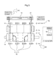
- FIG. 5 An example of the interface displayed by the display unit 52 is shown in Figure 5 .
- the interface shows schematically the rotary cutter 14 and the rotary anvil 16 and the cylinders 22. Temperature values 54 are displayed at different positions corresponding to the positions of the temperature sensors 30. In a similar way, a pressure value 56, the rotation speed values 58 of the rotary cutter 14 and of the rotary anvil 16, a time value 60 and vibration, slippage and temperature over threshold indicators 62 are displayed.
- the rotary cutting apparatus 10 may be operated for transmitting data and/or energy power using the following steps: a) measuring a working parameter with one of the sensors installed within the rotary cutting apparatus 10, b) determining data representative of the working parameter according to the measured working parameter, c) transmitting the processed data representative of the working parameter from the monitoring unit 28 to an interface transmission unit through wireless transmission, e.g. at frequency between 1 and 25 kHz.
- the rotary cutting apparatus 10 may also transmit power energy from a power energy generator fixed with respect to the frame 12 to the monitoring unit 28. The wireless transmission of data and power energy may be performed during the cutting operation.
- the rotary anvil 16 and the rotary cutter 14 may be provided with tight seals and protections so the maintenance may be carried out in the same way as for ordinary cutting apparatus.
- the monitoring unit 28 may comprise deformation gauges for measuring the deformation of the rotary cutter 14 and/or the rotary anvil 16, for example the deformation of the cutting edge 20.
- the interface may use standard or developed communications such as CANopen, Process Field Bus (Profibus) or a specific software.
- CANopen Process Field Bus
- Profile Process Field Bus
- the interface transmission unit 26 may also comprise alarms to signal abnormal data evolution and a possible need for maintenance and download ports, such as a Universal Serial Bus (USB) port, for directly downloading the data representative of the working parameters stored either in the memory 34 of the monitoring unit 28 and/or in a stationary memory of the interface transmission unit 26.
- a Universal Serial Bus USB
- both the rotary cutter 14 and the rotary anvil 16 comprise a monitoring unit 28 so as to transmit data and/or power energy from and to the interface transmission unit 26.
- the rotary cutting apparatus 10 may have only one of the rotary cutter 14 and the rotary anvil 16 comprising a monitoring unit 28.
Landscapes
- Life Sciences & Earth Sciences (AREA)
- Forests & Forestry (AREA)
- Engineering & Computer Science (AREA)
- Mechanical Engineering (AREA)
- Perforating, Stamping-Out Or Severing By Means Other Than Cutting (AREA)
- Arrangements For Transmission Of Measured Signals (AREA)
- Sawing (AREA)
- Details Of Cutting Devices (AREA)
- Machine Tool Sensing Apparatuses (AREA)
- Crushing And Pulverization Processes (AREA)
Abstract
Description
- The present disclosure relates to a rotary cutting apparatus comprising a monitoring unit (28) being at least partially embedded in at least one of the first and the second drums (37 or 38) of the first and the second rotary devices (14 or 16), the monitoring unit (28) being configured for measuring at least one working parameter and for transmitting data representative of the at least one working parameter between the monitoring unit (28) and an interface transmission unit positioned outside either the first or second rotary device or both.
- Furthermore, the present disclosure also relates to a method for transmitting data and energy.
- Rotary cutting apparatus is for example known from
EP-A-2 508 311 . - However, when using rotary cutting apparatus, functional disorders may occur with the apparatus and/or also the apparatus may be exposed to wear. A usual reaction of the skilled person to solve this is to increase the cutting pressure of the rotary cutting apparatus in order to obtain a good cut once again until the maximum pressure is reached. When this happens, there will be no other solution than to stop the rotary cutting apparatus in order to change the broken and/or worn parts. Thus, this will mean severe consequences for both productivity and efficiency of the rotary cutting apparatus. Furthermore, the increase of cutting pressure will also shorten the lifetime of the equipment.
- An aspect of the present disclosure is to provide an improved rotary cutting apparatus which will solve and/or reduce the problems mentioned above.
- The present disclosure therefore relates to a rotary cutting apparatus as defined in the permeable of
claim 1 further comprising a monitoring unit at least partially embedded in at least one of the first or the second drums of the first and the second rotary devices, the monitoring unit being configured for measuring at least one working parameter and for transmitting data representative of the at least one working parameter between the monitoring unit and an interface transmission unit positioned outside either the first or second rotary device or both. By measuring and following important working parameters, it will be possible to know when a maintenance operation is needed and also what maintenance is needed to be performed, such as for example preventive maintenance. A preventive maintenance operation is for example cleaning, checking and adjusting the equipment. - The monitoring unit, which is at least partially embedded in at least one of the first and the second drums will obtain, while machining is performed, accurate measurements relating to the cutting operation, such as the number of produced workpiece and/or a temperature of a cutting edge. Indeed, the position of the monitoring unit enables the disposition of sensing means very close to the external surface of the rotary device in which the monitoring unit is at least partially embedded thereby improving the accuracy of the measurements carried out in a remote position from the rotary devices and/or the cutting area.
- According to one embodiment the monitoring unit may be at least partially embedded in both of the first and second drums of the first and the second rotary devices.
- According to the present disclosure, the "cutting area" refers to a space closely surrounding the first and second rotary devices, particularly around a cutting edge provided onto the first or the second rotary device, when the rotary cutting apparatus is running.
- The at least one working parameter refers to a physical property or a dynamic behaviour or a state which is able to be measured or detected which relates to the cutting operation performed by the rotary cutting apparatus. The at least one working parameter may be a parameter related to the first and/or the second rotary device, the force means or any member of the rotary cutting apparatus participating to the cutting operation. Furthermore, the at least one working parameter may refer to any parameter which may be used to control the cutting operation.
- Data representative of the at least one working parameter refers to data determined from the measured and/or detected working parameter. For example, a sensor measures a working parameter so as to output data representative of this working parameter. Furthermore, data representative of the working parameter also refers to data calculated according to the working parameter, for example calculating another parameter according to the working parameter or determining that a threshold value is reached. Examples, but not limiting, of what working parameters may be measured and/or detected are vibrations, dirtiness of the equipment and temperature.
- Since the at least one working parameter is transmitted outside either the first or second rotary device or both while machining is performed, the monitoring unit allows a real-time control of the cutting operation. For example, it is possible to control the speed of rotation of the rotary devices and/or the feed speed of the workpiece.
- This real-time control will provide for the possibility to directly reacting and solving deviation within the operation by e.g. varying the process, operation and/or machining conditions according to the measured working parameters, thereby improving the productivity of the rotary cutting apparatus. Furthermore, by measuring working parameters related to the first and/or second rotary device itself, it is possible to know in real-time the activity of said rotary device so as to know when maintenance is needed and, particularly, what kind of maintenance is needed. For example, when said rotary cutting device should be replaced, sharpened or ground. Hence, real-time transmission of working parameters will allow more efficient scheduling of the maintenance. Thus, by combining monitored working parameters and performance data, the monitoring unit will enable insights on maintenance and performance data for optimizing productivity of the rotary cutting apparatus.
- According to one embodiment, the rotary cutting apparatus as defined hereinabove or hereinafter also comprises an interface transmission unit arranged onto the frame, wherein the monitoring unit is further configured for transmitting data through wireless transmission between the monitoring unit and the interface transmission unit.
- According to one embodiment, the monitoring unit is being configured for measuring one working parameter. According to another embodiment, the monitoring unit is being configured for measuring more than one working parameter.
- According to another embodiment, the monitoring unit as defined hereinabove or hereinafter is further configured for transmitting power energy through wireless transmission between the monitoring unit and the interface transmission unit. In the present disclosure, the term "power energy" refers to the energy needed to power the monitoring unit without the use of batteries. Thus, there will be no need to change batteries.
- Suitably, the monitoring unit is configured for transmitting data together with power energy at a frequency between 1 and 25kHz (between 1 and 25 thousand cycles per second) and it will enable wireless transmission of both data and power energy while avoiding unsatisfactory losses, which will happen when the wireless transmission is performed at high frequency, i.e. above 1 MHz (1 million cycles per second). When higher frequencies are used magnetic fields used for wireless transmission may be absorbed by the metals used in the equipment. If the magnetic fields are absorbed, they will heat the equipment which will cause problems. Therefore, the correct power energy frequency must be carefully selected.
- According to yet another embodiment of the present rotary cutter device as defined hereinabove or hereinafter, each of the first and second pair of bearing housings comprises a stationary bearing housing coupled to the frame and a rotary bearing housing coupled to the first or the second shaft, wherein the monitoring unit comprises a rotary antenna coupled to a rotary bearing housing; and the interface transmission unit comprises a stationary antenna coupled to a stationary bearing housing of a same first or second pair of bearing housings, and wherein the interface transmission unit and the monitoring unit are configured for transmitting data and/or power energy between the stationary and the rotary antennas through wireless transmission.
- Suitably, the monitoring unit comprises the at least one sensor for measuring at least one working parameter and outputting data representative of the at least one working parameter; a controller connected to the sensor for receiving data representative of the at least one working parameter, the controller being further configured for processing the data representative of the at least one working parameter and for transmitting the said data representative of the at least one working parameter to the interface transmission unit.
- The monitoring unit may comprise at least one sensor selected from the group of a temperature sensor, a vibration sensor, a load sensor and a rotation sensor.
- Suitably, the controller may comprise a memory for storing data which has been obtained from the sensor and/or data transmitted by the interface transmission unit and a calculator connected to the memory for calculating a new parameter. Since rotary tools can be assembled and disassembled in the rotary cutting apparatus several times, a memory which is able to store data obtained from the sensor or data transmitted by the interface transmission unit will allow the recovery and/also the surveillance of the operational history of the rotary cutting device at any time.
- According to one embodiment, the at least one working parameter is selected from at least one of: a temperature at an external surface of the first and/or the second rotary devices, a temperature difference between the first and/or the second rotary devices, a vibration level of the first and/or the second rotary devices, a slippage between the first and the second rotary devices, the number of cuts performed by the first and/or the second rotary device(s) and the number of revolutions of the first and/or the second rotary device(s).
- Suitably, the rotary cutting apparatus further comprises a display unit for displaying data transmitted by the monitoring unit.
- Furthermore, the above-identified aspect of the present disclosure will also be achieved by a method for transmitting data comprising the following steps: providing a rotary cutting apparatus as defined hereinabove or hereinafter; measuring at least one working parameter with the monitoring unit; processing the data representative of the at least one working parameter; and transmitting the processed data representative of the at least one working parameter from the monitoring unit to an interface transmission unit through wireless transmission.
- The method as defined hereinabove or hereinafter may further comprise the step of transmitting power energy from a power energy generator, positioned outside the first and/or the second rotary devices to the monitoring unit through wireless transmission.
- Suitably, the steps of measuring at least one working parameter, processing the data representative of the at least one working parameter and transmitting data and/or power energy are performed while the first and/or the second rotary devices is rotated.
- According to one embodiment of the method as defined hereinabove or hereinafter, one working parameter is measured. According to another embodiment of the method as defined hereinabove or hereinafter, more than one working parameter is measured.
- Further features and advantages of the present disclosure will become apparent from the following detailed description of embodiments, given as non-limiting examples, with reference to the accompanying drawings listed hereunder.
-
-
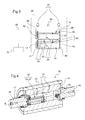
Figures 1 and 2 show schematically a perspective and a front views, respectively, of a rotary cutting apparatus with a rotary cutter and a rotary anvil in a cutting relationship. -
Figure 3 shows a diagram representing data transmission between the monitoring unit of the rotary cutter or the rotary anvil, shown inFigures 1 and 2 , and an interface transmission unit. -
Figure 4 shows schematically a cross-sectional view of the rotary anvil shown inFigures 1 and 2 . -
Figure 5 shows schematically an example of an interface of a display unit displaying data representative of a working parameter of the rotary cutting apparatus shown inFigures 1 and 2 . -
Figures 1 and 2 show arotary cutting apparatus 10 comprising aframe 12 adapted to be attached to a not-shown basement. In theframe 12, arotary cutter 14 and arotary anvil 16 are arranged. Therotary cutter 14 and therotary anvil 16 are shown in a cutting relationship. A cutting relationship refers to a specific position of therotary cutter 14 and therotary anvil 16 with respect to each other. Particularly, it refers to a position wherein acutting edge 20 of therotary cutter 14 is positioned close to the anvil's external surface, for example at a distance below 0.3 mm, or in contact with the anvil's external surface, depending on materials to be cut. - When a piece of web is passed through the
rotary anvil 16 and therotary cutter 14, thecutting edge 20 deforms the web until it is cut. The web may be selected from, for example but not limited to, non-woven material, woven material, plastic films, cellulose, cardboard, paper or metallic sheet. The products and trim obtained from the cutting operation may be separated directly by the effect of pressure, but may also be separated as they are moved in different directions or on different belts after the cutting operation. For instance, the product goes straight and trim goes upwards or downwards. - The
rotary cutter 14 is provided with anelongated cutter shaft 15 and acutter drum 38, thecutter drum 38 being coaxially arranged on thecutter shaft 15 about a rotation axis A. The shaft has an axial extension on each side of thecutter drum 38, where a pair ofcutter bearing housings 31 is provided, respectively. The pair ofcutter bearing housings 31 is each connected to theframe 12 by means of a fastening element, such as a screw. Thecutter shaft 15 is preferably made of steel and is adapted to be connected to a not shown rotatable power source. - The
cutter drum 38 is provided with a pair of annular support rings 18 and thecutting edge 20 for cutting articles from a web. Thecutter drum 38 may be provided with more than onecutting edge 20, for example thecutter drum 38 may comprise a pair of annular cutter sleeves, each provided with cutting members or cutting edges. The support rings 18 may be separate parts. Alternatively, one of the support rings may be an integrated part of a cutter sleeve and the other support ring may be an integrated part of the other cutter sleeve. The cuttingdrum 38 may also comprise an intermediate annular sleeve without cutting edges between the annular cutter sleeves, the intermediate sleeve and the cutter sleeve being coaxially arranged in relation to the axis A. Alternatively, thecutter drum 38 may be made of one single piece, forming an integrated annular sleeve, the axial extension of which corresponding to that of thecutter drum 38. - The support rings 18, the annular cutter sleeves and/or the intermediate annular sleeve may be made of steel and/or a cemented carbide and/or a cermet. The rings may be press-fitted, shrink-fitted, screwed or glued onto a portion of the
cutter shaft 15 having an enlarged diameter, altogether constituting saidcutter drum 38. - The
rotary anvil 16 is provided with anelongated anvil shaft 17 and ananvil drum 37, theanvil drum 37 being coaxially arranged on theanvil shaft 17 about a rotation axis B. - The
anvil drum 37 comprises a pair of support rings 18 and an annular anvil sleeve coaxial to the axis B. The annular anvil sleeve and the support rings 18 may be made as a single piece, forming an integrated annular sleeve, the axial extension of which corresponding to that of the anvil drum 37 (see alsoFigure 4 ). Alternatively, only one of the support rings may be an integrated part of the annular anvil sleeve. Alternatively, the support rings 18 may be separate parts. The annular anvil sleeve is preferably made of steel, but cemented carbide sleeves may also be used. - The support rings may be press-fitted or shrink-fitted or glued onto a portion of the
anvil shaft 17 having an enlarged diameter, altogether constituting said anvil drum 37 (see alsoFigure 4 ). - The support rings 18 of the
anvil drum 37 are adapted to bear against the support rings 18 of thecutter drum 38 for positioning therotary cutter 14 and therotary anvil 16 in a cutting relationship during the cutting operation. - The
anvil shaft 17 is arranged vertically above thecutter shaft 15 in such a way that the axis B is parallel to and is in the same plane as the axis A. Particularly, when theframe 12 is attached to a basement in a horizontal position, the axis B is parallel to and is in the same vertical plane as the axis A. Alternatively, the basement may be tilted relative to a horizontal or intermediate direction. - A pair of
anvil bearing housings 29 is arranged on either sides of theanvil drum 37 and connected to a pair ofcraddles 23 of a force means 22. - A pair of
cylinders 25 is used for pressing the craddles 23 including the pair ofanvil bearing housings 29 and thus also theanvil support ring 18 as well as the external surface of the annular anvil sleeve towards and against the support rings 18 and thecutting edge 20 of thecutter drum 38, respectively. Thecylinders 25 may be pneumaticly or hydraulicly moved. The cylinders may also be replaced by loading systems actuated by a screw-nut couple. - As shown in
Figure 3 , therotary cutting apparatus 10 comprises a cuttingunit 24 comprising therotary cutter 14 and therotary anvil 16, aninterface transmission unit 26 and adisplay unit 52. Each of therotary cutter 14 and therotary anvil 16 comprises amonitoring unit 28 for measuring a working parameter and for transmitting data representative of the working parameter between the monitoringunit 28 and an interface transmission unit positioned outside either the first or second rotary device or both. Themonitoring unit 28 is at least partially embedded in at least one of thecutter drum 37 oranvil drum 38 of therotary cutter 14 and therotary anvil 16. In other words, at least one member of themonitoring unit 28, for example a sensor, is partially embedded in at least one of thecutter drum 37 oranvil drum 38. The other members of themonitoring unit 28 may be disposed outside thecutter drum 37 oranvil drum 38, for example in a housing on the side of thecutter drum 37 oranvil drum 38. - For the sake of clarity, even if both of the
rotary cutter 14 and therotary anvil 16 comprise amonitoring unit 28, only themonitoring unit 28 of therotary anvil 16 is described below. Themonitoring unit 28 of therotary cutter 14 is structurally and functionally similar to themonitoring unit 28 of therotary anvil 16 described below. Alternatively, themonitoring unit 28 of therotary cutter 14 and therotary anvil 16 may be different. For example, themonitoring unit 28 of therotary cutter 14 and of therotary anvil 16 may comprise different types of sensors or themonitoring unit 28 may be differently embedded in thecutter 37 andanvil 38 drums. Alternatively, therotary cutting apparatus 10 may have only one of therotary cutter 14 and of therotary anvil 16 comprising amonitoring unit 28. - As shown in
Figures 3 and 4 , themonitoring unit 28 comprisestemperature sensors 30 disposed within therotary anvil 16 for measuring the temperature at the external surface of therotary anvil 16 and for sending out a signal representative of this temperature to acontroller 32 also placed/embedded within therotary anvil 16. Thecontroller 32 is configured for processing data representative of the working parameter received by thetemperature sensors 30 and for transmitting said data representative of the working parameter to theinterface transmission unit 26. Thetemperature sensors 30 will provide an indication as to the degree of thermal expansion of anvil's surface as an uneven thermal expansion will deform the tool and thereby disturb the cutting relationship. - Furthermore, the controller comprises a memory 34 and a calculator 35. The calculator 35 will enable the
controller 32 to calculate a calculated parameter with respect to the working parameter measured by the sensors, such as the temperature difference within therotary cutter 14 or therotary anvil 16, or such as a temperature level by comparing a measured temperature to a predetermined temperature threshold. - The memory 34 will enables the storage of data representative of the working parameter outputted by the sensors and data coming from the
interface transmission unit 26, such as a predetermined threshold. The data transmission from the sensors or from theinterface transmission unit 26 to the memory 34 may be carried out continuously or at regular time intervals, even when a cutting operation is operated. - In order for the at least partially embedded measuring unit of the
rotary anvil 16 to measure, process and store data representative of working parameter, thetemperature sensors 30, the calculator 35 and the memory 34 may be embedded in therotary anvil 16. As shown onfigure 4 , theanvil shaft 17 consists of twoend shafts 36 assembled at each end of acentral shaft 41 being coaxially arranged about the rotation axis B. Theend shafts 36 are adapted to be disassembled from thecentral shaft 41 for enabling maintenance work of thetemperature sensors 30, the calculator 35 and/or the memory 34. Alternatively, the calculator 35 and the memory 34 may be placed outside theanvil drum 37, for example integrated in a disk positioned on a side of theanvil drum 37. - Furthermore, for enabling recovery of the data representative of the working parameters processed by the
controller 32 and/or stored in the memory 34, themonitoring unit 28 comprises aconnector 40 reachable from outside therotary anvil 16. Theconnector 40 is configured to be connected in an assembled position of therotary anvil 16, i.e. a position in which therotary anvil 16 may be operated for a cutting process. Therefore, data may be recovered while the rotary cutting apparatus is operated so that theinterface transmission unit 26 is able to use data representative of the working parameters for controlling the cutting operation and/or to inform a user. Alternatively, data may also be recovered with theconnector 40 in a disassembled position of therotary anvil 16. Theconnector 40 may also be connected to an interface transmission unit, for example connected to a movable interface transmission unit or a computer, for recovering data representative of the working parameters in order to display or to document the history of therotary anvil 16 independently from therotary cutting apparatus 10. - For transmitting data representative of the working parameters on the exterior of the
rotary anvil 16, when therotary anvil 16 is assembled to therotary cutting apparatus 10, themonitoring unit 28 is configured for transmitting these data through wireless transmission. In this embodiment, themonitoring unit 28 further comprises arotary antenna 42 connected to theconnector 40. Therotary antenna 42 is coupled to therotary anvil 16 so that when therotary anvil 16 is rotated, therotary antenna 42 rotates in the same direction. For transmitting data representative of the working parameters to theinterface transmission unit 26, astationary antenna 44 is provided within theinterface transmission unit 26. Both the stationary 44 and rotary 42 antennas consist in wound coils magnetically coupled together to form an induction system, thus ensuring that wireless data are transmitted. For improving the efficiency and quality of the wireless transmission between the stationary 44 and rotary 42 antennas, the stationary 44 and rotary 42 antennas are positioned close to each other, Particularly, the pair anvil bearing housings 29 comprises a rotary bearing housing coupled to theend shaft 36 and a stationary bearing housing coupled to theframe 12. Therotary antenna 42 is coiled and coupled to the rotary bearing housing and thestationary antenna 44 is coiled and coupled to the stationary bearing housing. In this way, when the rotary cutting apparatus is being operated, therotary antenna 42 rotates together with therotary anvil 16, whereas the stationary antenna is static with respect to theframe 12. - For ensuring a constant operability of the
monitoring unit 28, the stationary 44 and rotary 42 antennas are further configured to transfer power energy though wireless transmission. In this way, therotary anvil 16 does not need any battery. For transferring both data and power energy, data signal and energy waves are superimposed at a same frequency. For an efficient wireless transmission of both data and power energy, the data signal and the energy waves are transmitted at a frequency between 1 and 25 kHz (between 1 and 25 thousand cycles per second). - For transferring data and energy power from the
interface transmission unit 26 to thecontroller 32, energy and data signals are superimposed and transmitted from thestationary antenna 44 to therotary antenna 42. The energy and data signals are then separated by a demodulation electronic circuit disposed within thecontroller 32 to store the energy signal in power capacities and the data signal in the memory 34. - For transferring measured temperatures from the
controller 32 to theinterface transmission unit 26, load modulation principle is performed. Particularly, the current in the primary circuit of the induction system consisting of the stationary 44 and rotary 42 antennas is varied and then demodulated by an analogic electronic circuit. The data signal is then stored in a memory installed within theinterface transmission unit 26. - The
rotary anvil 16 may have one or more stationary 44 and rotary 42 antennas. Furthermore, the number of stationary 44 and rotary 42 antennas will depend on whether to dissociate or associate data and energy in same stationary 44 and rotary 42 antennas or to create a possible backup. - The
monitoring unit 28 further comprisesvibration sensors 46,rotation sensors 48 andload sensors 50. - The
vibration sensors 46, such as accelerometers, are placed at different positions, for example on therotary anvil 16, on therotary cutter 14 or on the frame. Alternatively, thevibration sensors 46 may be also embedded in therotary cutter 14 and therotary anvil 16 and their data may be transmitted in the same way as described for the temperature data from thetemperature sensors 30. - The
rotation sensors 48 are associated with toothed wheels, one coupled to anend shaft 36 of therotary anvil 16 and another one coupled to anend shaft 39 of therotary cutter 14, to be able to determine the rotation speed of therotary cutter 14 and therotary anvil 16 and to detect the slippage between therotary cutter 14 and therotary anvil 16. Therotation sensors 48 may be of inductive, capacitive, Hall effect or encoder types. Alternatively, therotation sensors 48 may be also embedded in therotary cutter 14 and therotary anvil 16 and their data may be transmitted in the same way as described for the temperature data from thetemperature sensors 30. - The
load sensor 50 is physically placed within theinterface transmission unit 26 and measures the pressure applied on therotary anvil 16 by thecylinders 22. Theload sensors 50 may be load cells or pressure sensors in case of pneumatic or hydraulic loading systems. Alternatively, theload sensors 50 may also be embedded in therotary cutter 14 and/or therotary anvil 16 and their data may be transmitted in the same way as described for the temperature data from thetemperature sensors 30. - Furthermore, the
monitoring unit 28 is also configured to measure time through stationary and embedded clocks in order to track changes in a synchronized way. - The data representative of the working parameters are for example the temperature difference in the
rotary cutter 14, the temperature difference, typically the difference between the maximum and minimum temperatures in therotary anvil 16, the vibration level of therotary cutter 14, the vibration level of therotary anvil 16, the slippage betweenrotary anvil 16 androtary cutter 14, the rotation speed of therotary cutter 14, the rotation speed of therotary anvil 16, the pressure in thecylinders 22, the number of cuts performed by therotary cutter 14 and/or the number of cuts performed by therotary anvil 16. - The
rotary cutting apparatus 10 further comprises adisplay unit 52 for displaying the data representative of the measured working parameters or performance records. Thedisplay unit 52 comprises a Human Machine Interface (HMI), directly connected to theinterface transmission unit 26 for displaying by means of a screen with a High-Definition Multimedia Interface (HDMI) or Video Graphics Array (VGA) port. - An example of the interface displayed by the
display unit 52 is shown inFigure 5 . The interface shows schematically therotary cutter 14 and therotary anvil 16 and thecylinders 22. Temperature values 54 are displayed at different positions corresponding to the positions of thetemperature sensors 30. In a similar way, apressure value 56, the rotation speed values 58 of therotary cutter 14 and of therotary anvil 16, atime value 60 and vibration, slippage and temperature overthreshold indicators 62 are displayed. - The
rotary cutting apparatus 10 may be operated for transmitting data and/or energy power using the following steps: a) measuring a working parameter with one of the sensors installed within therotary cutting apparatus 10, b) determining data representative of the working parameter according to the measured working parameter, c) transmitting the processed data representative of the working parameter from themonitoring unit 28 to an interface transmission unit through wireless transmission, e.g. at frequency between 1 and 25 kHz. Therotary cutting apparatus 10 may also transmit power energy from a power energy generator fixed with respect to theframe 12 to themonitoring unit 28. The wireless transmission of data and power energy may be performed during the cutting operation. - For enabling maintenance of the
rotary cutter 14 and/or therotary anvil 16, such as re-grinding and re-sharpening, therotary anvil 16 and therotary cutter 14 may be provided with tight seals and protections so the maintenance may be carried out in the same way as for ordinary cutting apparatus. - Even though the present disclosure has been described with precise embodiments above, many variations are possible within the scope of the disclosure.
- For instance, the
monitoring unit 28 may comprise deformation gauges for measuring the deformation of therotary cutter 14 and/or therotary anvil 16, for example the deformation of thecutting edge 20. - Alternatively to the HMI, the interface may use standard or developed communications such as CANopen, Process Field Bus (Profibus) or a specific software.
- Furthermore, the
interface transmission unit 26 may also comprise alarms to signal abnormal data evolution and a possible need for maintenance and download ports, such as a Universal Serial Bus (USB) port, for directly downloading the data representative of the working parameters stored either in the memory 34 of themonitoring unit 28 and/or in a stationary memory of theinterface transmission unit 26. - In one of the embodiment described above, both the
rotary cutter 14 and therotary anvil 16 comprise amonitoring unit 28 so as to transmit data and/or power energy from and to theinterface transmission unit 26. Alternatively, therotary cutting apparatus 10 may have only one of therotary cutter 14 and therotary anvil 16 comprising amonitoring unit 28.
Claims (13)
- A rotary cutting apparatus (10) comprising:a frame (12);a first rotary device (14 or 16), such as a rotary cutter (14) or a rotary anvil (16), comprising a first shaft (15 or 17) concentrically arranged about a first rotational axis (A or B) and a first drum (37 or 38), such as an anvil drum (38) or a cutter drum (37), concentrically arranged on said first shaft (15 or 17), said first shaft (15 or 17) being provided with a first pair of housings (29 or 31) arranged on either sides of said first drum (37 or 38);a second rotary device (14 or 16) comprising a second shaft (15 or 17) concentrically arranged about a second rotational axis (A or B) and a second drum (37 or 38), such as an anvil drum (38) or a cutter drum (37), concentrically arranged on said second shaft (15 or 17), said second shaft (15 or 17) being provided with a second pair of housings (29 or 31) arranged on either sides of said first drum (37 or 38);said first and second rotary devices (14 or 16) being arranged in said frame (12) in such a way that said first and second rotational axes (A or B) are substantially horizontal and substantially in the same plane;said second shaft (15 or 17) being connected to the frame (12) via said second pair of bearing housings (29 or 31);said first shaft (15 or 17) being associated with said frame (12) via said first pair of bearing housing (29 or 31), said first pair of bearing housings (29 or 31) being movable relative to the frame (12) in a transverse direction to said first rotational axis (A or B) by means of a force means (22) such that the first and second drums come into a cutting relationship with one another; characterized in that:a monitoring unit (28) is at least partially embedded in at least one of the first or the second drums (37 or 38) of the first and the second rotary devices (14 or 16), the monitoring unit (28) being configured for measuring at least one working parameter and for transmitting data representative of the at least one working parameter between the monitoring unit (28) and an interface transmission unit positioned outside either the first or second rotary device or both.
- The rotary cutting apparatus (10) according to claim 1, further comprising an interface transmission unit (26) arranged on the frame (12), wherein the monitoring unit (28) is further configured for transmitting data through wireless transmission between the monitoring unit (28) and the interface transmission unit (26).
- The rotary cutting apparatus (10) according to claim 1 or 2, wherein the monitoring unit (28) is further configured for transmitting power energy through wireless transmission between the monitoring unit and the interface transmission unit (26).
- The rotary cutting apparatus (10) according to claim 3, wherein the monitoring unit (28) is configured for transmitting data together with power energy at a frequency between 1 and 25kHz.
- The rotary cutting apparatus (10) according to claim 3 or 4, wherein each of the first and second pair of bearing housings (29 or 31) comprises a stationary bearing housing coupled to the frame and a rotary bearing housing coupled to the first or the second shaft (15 or 17), wherein:the monitoring unit (28) comprises a rotary antenna (42) coupled to a rotary bearing housing; andthe interface transmission unit (26) comprises a stationary antenna (44) coupled to a stationary bearing housing of a same first or second pair of bearing housings (29 or 31), andwherein the interface transmission unit (26) and the monitoring unit (28) are configured for transmitting data and/or power energy between the stationary (44) and the rotary (42) antennas through wireless transmission.
- The rotary cutting apparatus (10) according to any one of claims 3 to 5, wherein the monitoring unit (28) comprises:at least one sensor for measuring at least one working parameter and outputting data representative of the at least one working parameter;a controller (32) connected to the sensor for receiving data representative of the at least one working parameter, the controller (32) being further configured for processing the data representative of the at least one working parameter and for transmitting said processed data representative of the at least one working parameter to the interface transmission unit (26).
- The rotary cutting apparatus (10) according to any one of the preceding claims, wherein the monitoring unit (28) comprises at least one sensor selected from at least one of a temperature sensor (30), a vibration sensor (46), a load sensor (50) and a rotation sensor (48).
- The rotary cutting apparatus (10) according to claim 6 or 7, wherein the controller (32) comprises:a memory (34) for storing data outputted by the sensor or data transmitted by the interface transmission unit (26);a calculator (35) connected to the memory (34) for calculating a calculated parameter with respect to the data representative of the at least one working parameter outputted by the sensor.
- The rotary cutting apparatus (10) according to any one of the preceding claims, wherein the data representative of the at least working parameter is selected from at least one of: a temperature at an external surface of the first and/or the second rotary devices (14 or 16), a temperature difference in the first and/or the second rotary devices (14 or 16), a vibration level of the first and/or the second rotary devices (14 or 16), a slippage between the first and the second rotary devices (14 or 16), a number of cuts done by the first and/or the second rotary devices (14 or 16) and a number of revolutions of the first and/or the second rotary devices (14 or 16).
- The rotary cutting apparatus (10) according to any one of the preceding claims, further comprising a display unit (52) for displaying data transmitted by the monitoring unit (28).
- A method for transmitting data comprising in the following steps:providing a rotary cutting apparatus (10) according to any one of claims 3-10;measuring at least one working parameter with the monitoring unit (28);determining data representative of the at least one working parameter according to the measured working parameter;processing the data representative of the at least one working parameter;transmitting the processed data representative of the at least one working parameter from the monitoring unit (28) to an interface transmission unit through wireless transmission.
- The method according to claim 11, further comprising the step of transmitting power energy from a power energy generator, positioned outside the at least one among the first and the second rotary devices (14 or 16) including the monitoring unit (28), to the monitoring unit (28) through wireless transmission.
- The method according to claim 11 or 12, the step of measuring at least one working parameter, determining and processing the data representative of the at least one working parameter and transmitting data and/or power energy are performed while the at least one among the first and the second rotary devices (14 or 16) including the monitoring unit (28) is rotated.
Priority Applications (12)
| Application Number | Priority Date | Filing Date | Title |
|---|---|---|---|
| TR2018/07612T TR201807612T4 (en) | 2015-10-06 | 2015-10-06 | Rotary cutting apparatus with built-in monitoring unit. |
| EP15306573.5A EP3153285B1 (en) | 2015-10-06 | 2015-10-06 | A rotary cutting apparatus with an embedded monitoring unit |
| HUE15306573A HUE039651T2 (en) | 2015-10-06 | 2015-10-06 | A rotary cutting apparatus with an embedded monitoring unit |
| ES15306573.5T ES2675850T3 (en) | 2015-10-06 | 2015-10-06 | Rotary cutting device with an integrated monitoring unit |
| PL15306573T PL3153285T3 (en) | 2015-10-06 | 2015-10-06 | A rotary cutting apparatus with an embedded monitoring unit |
| KR1020187008868A KR102528635B1 (en) | 2015-10-06 | 2016-10-03 | Rotary cutting unit with integrated monitoring unit |
| PCT/EP2016/073562 WO2017060196A1 (en) | 2015-10-06 | 2016-10-03 | A rotary cutting apparatus with an embedded monitoring unit |
| BR112018006921-3A BR112018006921B1 (en) | 2015-10-06 | 2016-10-03 | rotary cutter and method for data transmission comprising the rotary cutter |
| US15/762,634 US10695930B2 (en) | 2015-10-06 | 2016-10-03 | Rotary cutting apparatus with an embedded monitoring unit |
| CN201680056454.8A CN108025449B (en) | 2015-10-06 | 2016-10-03 | Rotary cutting equipment with embedded monitoring unit |
| MX2018004104A MX377324B (en) | 2015-10-06 | 2016-10-03 | A ROTARY CUTTING APPLIANCE WITH A BUILT-IN MONITORING UNIT. |
| JP2018517545A JP6863972B2 (en) | 2015-10-06 | 2016-10-03 | Rotary cutting device with embedded monitoring unit |
Applications Claiming Priority (1)
| Application Number | Priority Date | Filing Date | Title |
|---|---|---|---|
| EP15306573.5A EP3153285B1 (en) | 2015-10-06 | 2015-10-06 | A rotary cutting apparatus with an embedded monitoring unit |
Publications (2)
| Publication Number | Publication Date |
|---|---|
| EP3153285A1 true EP3153285A1 (en) | 2017-04-12 |
| EP3153285B1 EP3153285B1 (en) | 2018-05-16 |
Family
ID=54288734
Family Applications (1)
| Application Number | Title | Priority Date | Filing Date |
|---|---|---|---|
| EP15306573.5A Active EP3153285B1 (en) | 2015-10-06 | 2015-10-06 | A rotary cutting apparatus with an embedded monitoring unit |
Country Status (12)
| Country | Link |
|---|---|
| US (1) | US10695930B2 (en) |
| EP (1) | EP3153285B1 (en) |
| JP (1) | JP6863972B2 (en) |
| KR (1) | KR102528635B1 (en) |
| CN (1) | CN108025449B (en) |
| BR (1) | BR112018006921B1 (en) |
| ES (1) | ES2675850T3 (en) |
| HU (1) | HUE039651T2 (en) |
| MX (1) | MX377324B (en) |
| PL (1) | PL3153285T3 (en) |
| TR (1) | TR201807612T4 (en) |
| WO (1) | WO2017060196A1 (en) |
Cited By (1)
| Publication number | Priority date | Publication date | Assignee | Title |
|---|---|---|---|---|
| IT201700050040A1 (en) * | 2017-05-09 | 2018-11-09 | Rca Bignami Srl | ROLLER CUTTING GROUP, PARTICULARLY FOR RIBBON MATERIALS. |
Families Citing this family (4)
| Publication number | Priority date | Publication date | Assignee | Title |
|---|---|---|---|---|
| ES2675850T3 (en) * | 2015-10-06 | 2018-07-13 | Sandvik Intellectual Property Ab | Rotary cutting device with an integrated monitoring unit |
| US10857690B2 (en) | 2018-09-11 | 2020-12-08 | The Procter & Gamble Company | Method and apparatus for adjusting and maintaining a position of a cutting surface of a perforating apparatus |
| TR202003061A1 (en) | 2020-02-28 | 2021-09-21 | Saueressig Baski Oencesi Hazirlik Sistemleri Sanayi Ticaret Anonim Sirketi | A PRINTING CYLINDER ASSEMBLY |
| CN119416291B (en) * | 2025-01-07 | 2025-05-13 | 天津天海同步科技有限公司 | Cutting tooth machining unfolding chip geometric model building system |
Citations (5)
| Publication number | Priority date | Publication date | Assignee | Title |
|---|---|---|---|---|
| EP0841132A1 (en) * | 1996-11-06 | 1998-05-13 | Maysun Co., Ltd. | Contact pressure control method and device for rotary cutter |
| WO2000073029A1 (en) * | 1999-05-28 | 2000-12-07 | Fabio Perini S.P.A. | Device with thermal system for controlling the interference between two members moving relative to each other |
| EP1798011A1 (en) * | 2005-12-17 | 2007-06-20 | Bikoma Aktiengesellschaft Spezialmaschinen | Rotary cutter |
| EP2508311A1 (en) | 2011-04-08 | 2012-10-10 | Sandvik Intellectual Property AB | A rotary cutting apparatus with vibration attenuation means |
| CN203432616U (en) * | 2013-08-27 | 2014-02-12 | 昆明理工大学 | An apparatus for detecting load parameters of a ball mill |
Family Cites Families (34)
| Publication number | Priority date | Publication date | Assignee | Title |
|---|---|---|---|---|
| GB1483318A (en) * | 1975-03-20 | 1977-08-17 | Coal Ind | Mining machines |
| US4325580A (en) * | 1979-05-07 | 1982-04-20 | Cmi Corporation | Roadway planing apparatus |
| JPS60175697A (en) * | 1984-02-23 | 1985-09-09 | 財団法人石炭技術研究所 | Double ranging drum cutter having rock sensor by imaging treatment system |
| US4580144A (en) * | 1984-08-20 | 1986-04-01 | Pitney Bowes Inc. | Postal fixed and variable data thermal printer |
| DE3730392A1 (en) * | 1987-09-10 | 1989-03-30 | Winkler Duennebier Kg Masch | METHOD AND DEVICE FOR KEEPING THE CUTTING CONDITIONS CONSTANT ON A ROTARY PUNCH |
| US5048387A (en) * | 1989-07-14 | 1991-09-17 | Komori Corporation | Horizontal perforation forming apparatus for rotary press |
| JPH07119551B2 (en) * | 1990-07-13 | 1995-12-20 | 株式会社小松製作所 | Driving support device for excavation type underground excavator |
| US5058496A (en) * | 1990-09-17 | 1991-10-22 | Integrated Design Corp. | Roll apparatus with cooling system for maintaining constant gap size and method |
| JP3285713B2 (en) * | 1994-08-25 | 2002-05-27 | 理想科学工業株式会社 | Plate making and printing equipment |
| JP3729608B2 (en) * | 1997-07-01 | 2005-12-21 | 理想科学工業株式会社 | Plate making printer |
| US6188222B1 (en) * | 1997-09-19 | 2001-02-13 | Schlumberger Technology Corporation | Method and apparatus for measuring resistivity of an earth formation |
| US6886439B2 (en) * | 2001-02-02 | 2005-05-03 | Teck Cominco Metals Ltd. | Paper elimination in the production of battery plates |
| US6911828B1 (en) * | 2001-05-23 | 2005-06-28 | Southwest Research Institute | Apparatus and method for detecting the degradation of a coating using embedded sensors |
| JP4495393B2 (en) * | 2001-08-29 | 2010-07-07 | 株式会社瑞光 | Manufacturing method of article |
| TW491743B (en) * | 2001-09-28 | 2002-06-21 | Ind Tech Res Inst | Internal active compensation method and device for axial swinging of rotatory shaft tool |
| US6848503B2 (en) * | 2002-01-17 | 2005-02-01 | Halliburton Energy Services, Inc. | Wellbore power generating system for downhole operation |
| US6844814B2 (en) * | 2002-11-12 | 2005-01-18 | Motorola, Inc. | Wireless sensor apparatus and method |
| ITBO20030708A1 (en) * | 2003-11-24 | 2005-05-25 | Gd Spa | METHOD FOR PREDICTIVE MAINTENANCE OF A UNIT OF |
| JP2007529344A (en) * | 2004-03-18 | 2007-10-25 | ヴェーエムイー エペ ホーランド ベー.ヴェー. | Cutting device |
| SE527556C2 (en) * | 2004-07-02 | 2006-04-11 | Sandvik Intellectual Property | A support roller for a rotary knife unit and a rotation knife unit with such a support roller |
| GB2435189B (en) * | 2004-12-17 | 2010-06-23 | Milwaukee Electric Tool Corp | Saw and Blade with Operational Communication |
| SE529998C2 (en) * | 2005-04-07 | 2008-02-05 | Sandvik Intellectual Property | A support roll drum and a support roll unit for a rotatable cutting device |
| DE102005022604A1 (en) * | 2005-05-11 | 2006-11-16 | Aichele Werkzeuge Gmbh | Rotary cutting device, method for decommissioning a rotary cutting device and method for operating a rotary cutting device |
| SE531300C2 (en) * | 2006-01-31 | 2009-02-17 | Tetra Laval Holdings & Finance | A system and method for regulating and smoothing the temperature of two cooperating cylinders forming a nip through which a web is conducted |
| JP4974639B2 (en) * | 2006-10-20 | 2012-07-11 | 日東電工株式会社 | Adhesive tape cutting method and apparatus using the same |
| US20090093974A1 (en) * | 2007-10-04 | 2009-04-09 | James Glass | Machine-Independent Roller Counting System |
| US9102818B2 (en) * | 2010-05-17 | 2015-08-11 | Highcon Systems Ltd. | Method and system for surface adhesive rule technology |
| SE536109C2 (en) * | 2011-04-08 | 2013-05-07 | Sandvik Intellectual Property | Rotary cutting apparatus with vibration damping means |
| US9222350B2 (en) * | 2011-06-21 | 2015-12-29 | Diamond Innovations, Inc. | Cutter tool insert having sensing device |
| PL2656988T3 (en) * | 2012-04-27 | 2016-09-30 | Cutting unit comprising a stationary frame, a cutting drum, and an anvil drum | |
| US20140033886A1 (en) * | 2012-08-01 | 2014-02-06 | Xerox Corporation | Document Production System and Method With Automated Die Exchange |
| US9067335B2 (en) * | 2012-08-08 | 2015-06-30 | Container Graphics Corporation | Resilient finger scrap stripper for corrugated board rotary cutting die |
| US10329855B2 (en) * | 2013-12-06 | 2019-06-25 | Schlumberger Technology Corporation | Control line assembly and fabrication technique |
| ES2675850T3 (en) * | 2015-10-06 | 2018-07-13 | Sandvik Intellectual Property Ab | Rotary cutting device with an integrated monitoring unit |
-
2015
- 2015-10-06 ES ES15306573.5T patent/ES2675850T3/en active Active
- 2015-10-06 PL PL15306573T patent/PL3153285T3/en unknown
- 2015-10-06 EP EP15306573.5A patent/EP3153285B1/en active Active
- 2015-10-06 HU HUE15306573A patent/HUE039651T2/en unknown
- 2015-10-06 TR TR2018/07612T patent/TR201807612T4/en unknown
-
2016
- 2016-10-03 BR BR112018006921-3A patent/BR112018006921B1/en active IP Right Grant
- 2016-10-03 WO PCT/EP2016/073562 patent/WO2017060196A1/en not_active Ceased
- 2016-10-03 KR KR1020187008868A patent/KR102528635B1/en active Active
- 2016-10-03 JP JP2018517545A patent/JP6863972B2/en active Active
- 2016-10-03 US US15/762,634 patent/US10695930B2/en active Active
- 2016-10-03 MX MX2018004104A patent/MX377324B/en active IP Right Grant
- 2016-10-03 CN CN201680056454.8A patent/CN108025449B/en active Active
Patent Citations (5)
| Publication number | Priority date | Publication date | Assignee | Title |
|---|---|---|---|---|
| EP0841132A1 (en) * | 1996-11-06 | 1998-05-13 | Maysun Co., Ltd. | Contact pressure control method and device for rotary cutter |
| WO2000073029A1 (en) * | 1999-05-28 | 2000-12-07 | Fabio Perini S.P.A. | Device with thermal system for controlling the interference between two members moving relative to each other |
| EP1798011A1 (en) * | 2005-12-17 | 2007-06-20 | Bikoma Aktiengesellschaft Spezialmaschinen | Rotary cutter |
| EP2508311A1 (en) | 2011-04-08 | 2012-10-10 | Sandvik Intellectual Property AB | A rotary cutting apparatus with vibration attenuation means |
| CN203432616U (en) * | 2013-08-27 | 2014-02-12 | 昆明理工大学 | An apparatus for detecting load parameters of a ball mill |
Cited By (2)
| Publication number | Priority date | Publication date | Assignee | Title |
|---|---|---|---|---|
| IT201700050040A1 (en) * | 2017-05-09 | 2018-11-09 | Rca Bignami Srl | ROLLER CUTTING GROUP, PARTICULARLY FOR RIBBON MATERIALS. |
| EP3401066A1 (en) * | 2017-05-09 | 2018-11-14 | RCA Bignami S.R.L. | A roller cutter unit, particularly for ribbon materials |
Also Published As
| Publication number | Publication date |
|---|---|
| JP2018535103A (en) | 2018-11-29 |
| CN108025449A (en) | 2018-05-11 |
| KR20180063095A (en) | 2018-06-11 |
| WO2017060196A1 (en) | 2017-04-13 |
| CN108025449B (en) | 2020-01-21 |
| MX2018004104A (en) | 2018-05-17 |
| BR112018006921A2 (en) | 2018-10-16 |
| TR201807612T4 (en) | 2018-06-21 |
| KR102528635B1 (en) | 2023-05-03 |
| ES2675850T3 (en) | 2018-07-13 |
| US20180354149A1 (en) | 2018-12-13 |
| US10695930B2 (en) | 2020-06-30 |
| BR112018006921B1 (en) | 2021-02-17 |
| JP6863972B2 (en) | 2021-04-21 |
| EP3153285B1 (en) | 2018-05-16 |
| PL3153285T3 (en) | 2018-10-31 |
| HUE039651T2 (en) | 2019-01-28 |
| MX377324B (en) | 2025-03-07 |
Similar Documents
| Publication | Publication Date | Title |
|---|---|---|
| US10695930B2 (en) | Rotary cutting apparatus with an embedded monitoring unit | |
| Rizal et al. | An embedded multi-sensor system on the rotating dynamometer for real-time condition monitoring in milling | |
| KR102153142B1 (en) | An arrangement for controlling the process of rotary chip removing machining of a workpiece, and a cutting tool for rotary chip removing machining | |
| JP6920092B2 (en) | Drilling system, drill abnormality detection method and manufacturing method of the product to be drilled | |
| CN103009187B (en) | The monitoring method of the rotating shaft rotating speed in lathe and monitoring device, lathe | |
| JP7049978B2 (en) | Cutting system, machining error measuring method, and machining error measuring device | |
| EP3954978A1 (en) | Method and apparatus for measuring and removing rotational variability from a nip pressure profile of a covered roll of a nip press | |
| US9751185B2 (en) | Assembly having a handheld power tool and a roughing disk | |
| JP2018054611A (en) | Vibration measuring device | |
| US20100186560A1 (en) | Apparatus and method for controlling the machining of workpieces using piezoceramic transducers | |
| KR20140144351A (en) | Setting method of revolutions per minute on the real time of a spinning cutting tool, and the control device | |
| CN106463822B (en) | Apparatus and method for telemetrically transmitting data from a measurement unit of a system to a base station | |
| KR101407861B1 (en) | Wear of Cutting Tool Wear and sensing devices using the same cutting tool detection methods | |
| KR101212880B1 (en) | A machine vibration monitoring system | |
| JPH09174383A (en) | Method and device for detecting abnormality of rotating tool | |
| JP6879057B2 (en) | Monitoring system | |
| JP5356816B2 (en) | Tool condition monitoring system | |
| WO2022264047A1 (en) | Wear monitoring system and method for monitoring bearing wear in a roller for an undercarriage track system | |
| JP2001150244A (en) | Method for operating gear shaping machine | |
| EP3500400A1 (en) | Method and apparatus for cutting true with a round saw | |
| JP4742821B2 (en) | Drive shaft damage diagnosis device | |
| AU2017313142A1 (en) | Method and apparatus for cutting true with a round saw | |
| SE535714C2 (en) | Tool monitoring |
Legal Events
| Date | Code | Title | Description |
|---|---|---|---|
| PUAI | Public reference made under article 153(3) epc to a published international application that has entered the european phase |
Free format text: ORIGINAL CODE: 0009012 |
|
| STAA | Information on the status of an ep patent application or granted ep patent |
Free format text: STATUS: THE APPLICATION HAS BEEN PUBLISHED |
|
| AK | Designated contracting states |
Kind code of ref document: A1 Designated state(s): AL AT BE BG CH CY CZ DE DK EE ES FI FR GB GR HR HU IE IS IT LI LT LU LV MC MK MT NL NO PL PT RO RS SE SI SK SM TR |
|
| AX | Request for extension of the european patent |
Extension state: BA ME |
|
| STAA | Information on the status of an ep patent application or granted ep patent |
Free format text: STATUS: REQUEST FOR EXAMINATION WAS MADE |
|
| 17P | Request for examination filed |
Effective date: 20171010 |
|
| RBV | Designated contracting states (corrected) |
Designated state(s): AL AT BE BG CH CY CZ DE DK EE ES FI FR GB GR HR HU IE IS IT LI LT LU LV MC MK MT NL NO PL PT RO RS SE SI SK SM TR |
|
| GRAP | Despatch of communication of intention to grant a patent |
Free format text: ORIGINAL CODE: EPIDOSNIGR1 |
|
| STAA | Information on the status of an ep patent application or granted ep patent |
Free format text: STATUS: GRANT OF PATENT IS INTENDED |
|
| INTG | Intention to grant announced |
Effective date: 20180213 |
|
| RIC1 | Information provided on ipc code assigned before grant |
Ipc: B26F 1/38 20060101ALN20180202BHEP Ipc: B26D 7/26 20060101AFI20180202BHEP |
|
| GRAS | Grant fee paid |
Free format text: ORIGINAL CODE: EPIDOSNIGR3 |
|
| GRAA | (expected) grant |
Free format text: ORIGINAL CODE: 0009210 |
|
| STAA | Information on the status of an ep patent application or granted ep patent |
Free format text: STATUS: THE PATENT HAS BEEN GRANTED |
|
| AK | Designated contracting states |
Kind code of ref document: B1 Designated state(s): AL AT BE BG CH CY CZ DE DK EE ES FI FR GB GR HR HU IE IS IT LI LT LU LV MC MK MT NL NO PL PT RO RS SE SI SK SM TR |
|
| REG | Reference to a national code |
Ref country code: GB Ref legal event code: FG4D |
|
| REG | Reference to a national code |
Ref country code: CH Ref legal event code: EP |
|
| REG | Reference to a national code |
Ref country code: IE Ref legal event code: FG4D |
|
| REG | Reference to a national code |
Ref country code: DE Ref legal event code: R096 Ref document number: 602015011131 Country of ref document: DE |
|
| REG | Reference to a national code |
Ref country code: AT Ref legal event code: REF Ref document number: 999116 Country of ref document: AT Kind code of ref document: T Effective date: 20180615 |
|
| REG | Reference to a national code |
Ref country code: ES Ref legal event code: FG2A Ref document number: 2675850 Country of ref document: ES Kind code of ref document: T3 Effective date: 20180713 |
|
| REG | Reference to a national code |
Ref country code: SE Ref legal event code: TRGR |
|
| REG | Reference to a national code |
Ref country code: NL Ref legal event code: FP |
|
| REG | Reference to a national code |
Ref country code: GB Ref legal event code: 732E Free format text: REGISTERED BETWEEN 20180913 AND 20180919 Ref country code: LT Ref legal event code: MG4D |
|
| REG | Reference to a national code |
Ref country code: FR Ref legal event code: PLFP Year of fee payment: 4 |
|
| PG25 | Lapsed in a contracting state [announced via postgrant information from national office to epo] |
Ref country code: BG Free format text: LAPSE BECAUSE OF FAILURE TO SUBMIT A TRANSLATION OF THE DESCRIPTION OR TO PAY THE FEE WITHIN THE PRESCRIBED TIME-LIMIT Effective date: 20180816 Ref country code: FI Free format text: LAPSE BECAUSE OF FAILURE TO SUBMIT A TRANSLATION OF THE DESCRIPTION OR TO PAY THE FEE WITHIN THE PRESCRIBED TIME-LIMIT Effective date: 20180516 Ref country code: NO Free format text: LAPSE BECAUSE OF FAILURE TO SUBMIT A TRANSLATION OF THE DESCRIPTION OR TO PAY THE FEE WITHIN THE PRESCRIBED TIME-LIMIT Effective date: 20180816 Ref country code: LT Free format text: LAPSE BECAUSE OF FAILURE TO SUBMIT A TRANSLATION OF THE DESCRIPTION OR TO PAY THE FEE WITHIN THE PRESCRIBED TIME-LIMIT Effective date: 20180516 |
|
| PG25 | Lapsed in a contracting state [announced via postgrant information from national office to epo] |
Ref country code: HR Free format text: LAPSE BECAUSE OF FAILURE TO SUBMIT A TRANSLATION OF THE DESCRIPTION OR TO PAY THE FEE WITHIN THE PRESCRIBED TIME-LIMIT Effective date: 20180516 Ref country code: RS Free format text: LAPSE BECAUSE OF FAILURE TO SUBMIT A TRANSLATION OF THE DESCRIPTION OR TO PAY THE FEE WITHIN THE PRESCRIBED TIME-LIMIT Effective date: 20180516 Ref country code: GR Free format text: LAPSE BECAUSE OF FAILURE TO SUBMIT A TRANSLATION OF THE DESCRIPTION OR TO PAY THE FEE WITHIN THE PRESCRIBED TIME-LIMIT Effective date: 20180817 Ref country code: LV Free format text: LAPSE BECAUSE OF FAILURE TO SUBMIT A TRANSLATION OF THE DESCRIPTION OR TO PAY THE FEE WITHIN THE PRESCRIBED TIME-LIMIT Effective date: 20180516 |
|
| REG | Reference to a national code |
Ref country code: SK Ref legal event code: T3 Ref document number: E 28139 Country of ref document: SK |
|
| REG | Reference to a national code |
Ref country code: AT Ref legal event code: MK05 Ref document number: 999116 Country of ref document: AT Kind code of ref document: T Effective date: 20180516 |
|
| REG | Reference to a national code |
Ref country code: DE Ref legal event code: R082 Ref document number: 602015011131 Country of ref document: DE Representative=s name: KRAUS & WEISERT PATENTANWAELTE PARTGMBB, DE Ref country code: DE Ref legal event code: R081 Ref document number: 602015011131 Country of ref document: DE Owner name: SANDVIK HYPERION AB, SE Free format text: FORMER OWNER: SANDVIK INTELLECTUAL PROPERTY AB, SANDVIKEN, SE Ref country code: DE Ref legal event code: R081 Ref document number: 602015011131 Country of ref document: DE Owner name: HYPERION MATERIALS & TECHNOLOGIES (SWEDEN) AB, SE Free format text: FORMER OWNER: SANDVIK INTELLECTUAL PROPERTY AB, SANDVIKEN, SE |
|
| REG | Reference to a national code |
Ref country code: BE Ref legal event code: PD Owner name: SANDVIK HYPERION AB; SE Free format text: DETAILS ASSIGNMENT: CHANGE OF OWNER(S), CESSION; FORMER OWNER NAME: SANDVIK INTELLECTUAL PROPERTY AB Effective date: 20181128 |
|
| REG | Reference to a national code |
Ref country code: DE Ref legal event code: R081 Ref document number: 602015011131 Country of ref document: DE Owner name: HYPERION MATERIALS & TECHNOLOGIES (SWEDEN) AB, SE Free format text: FORMER OWNER: SANDVIK HYPERION AB, STOCKHOLM, SE Ref country code: HU Ref legal event code: AG4A Ref document number: E039651 Country of ref document: HU Ref country code: DE Ref legal event code: R082 Ref document number: 602015011131 Country of ref document: DE Representative=s name: KRAUS & WEISERT PATENTANWAELTE PARTGMBB, DE |
|
| PG25 | Lapsed in a contracting state [announced via postgrant information from national office to epo] |
Ref country code: RO Free format text: LAPSE BECAUSE OF FAILURE TO SUBMIT A TRANSLATION OF THE DESCRIPTION OR TO PAY THE FEE WITHIN THE PRESCRIBED TIME-LIMIT Effective date: 20180516 Ref country code: EE Free format text: LAPSE BECAUSE OF FAILURE TO SUBMIT A TRANSLATION OF THE DESCRIPTION OR TO PAY THE FEE WITHIN THE PRESCRIBED TIME-LIMIT Effective date: 20180516 Ref country code: AT Free format text: LAPSE BECAUSE OF FAILURE TO SUBMIT A TRANSLATION OF THE DESCRIPTION OR TO PAY THE FEE WITHIN THE PRESCRIBED TIME-LIMIT Effective date: 20180516 Ref country code: DK Free format text: LAPSE BECAUSE OF FAILURE TO SUBMIT A TRANSLATION OF THE DESCRIPTION OR TO PAY THE FEE WITHIN THE PRESCRIBED TIME-LIMIT Effective date: 20180516 |
|
| RAP2 | Party data changed (patent owner data changed or rights of a patent transferred) |
Owner name: SANDVIK HYPERION AB |
|
| REG | Reference to a national code |
Ref country code: NL Ref legal event code: PD Owner name: SANDVIK HYPERION AB; SE Free format text: DETAILS ASSIGNMENT: CHANGE OF OWNER(S), ASSIGNMENT; FORMER OWNER NAME: SANDVIK INTELLECTUAL PROPERTY AB Effective date: 20181214 |
|
| REG | Reference to a national code |
Ref country code: DE Ref legal event code: R097 Ref document number: 602015011131 Country of ref document: DE |
|
| PG25 | Lapsed in a contracting state [announced via postgrant information from national office to epo] |
Ref country code: SM Free format text: LAPSE BECAUSE OF FAILURE TO SUBMIT A TRANSLATION OF THE DESCRIPTION OR TO PAY THE FEE WITHIN THE PRESCRIBED TIME-LIMIT Effective date: 20180516 |
|
| REG | Reference to a national code |
Ref country code: HU Ref legal event code: GB9C Owner name: SANDVIK HYPERION AB, SE Free format text: FORMER OWNER(S): SANDVIK INTELLECTUAL PROPERTY AB, SE |
|
| RAP2 | Party data changed (patent owner data changed or rights of a patent transferred) |
Owner name: HYPERION MATERIALS & TECHNOLOGIES (SWEDEN) AB |
|
| REG | Reference to a national code |
Ref country code: BE Ref legal event code: HC Owner name: HYPERION MATERIALS & TECHNOLOGIES (SWEDEN) AB; SE Free format text: DETAILS ASSIGNMENT: CHANGE OF OWNER(S), CHANGEMENT DE NOM DU PROPRIETAIRE; FORMER OWNER NAME: SANDVIK HYPERION AB Effective date: 20190123 |
|
| PLBE | No opposition filed within time limit |
Free format text: ORIGINAL CODE: 0009261 |
|
| STAA | Information on the status of an ep patent application or granted ep patent |
Free format text: STATUS: NO OPPOSITION FILED WITHIN TIME LIMIT |
|
| 26N | No opposition filed |
Effective date: 20190219 |
|
| REG | Reference to a national code |
Ref country code: HU Ref legal event code: HC9C Owner name: HYPERION MATERIALS & TECHNOLOGIES, SE Free format text: FORMER OWNER(S): SANDVIK INTELLECTUAL PROPERTY AB, SE; SANDVIK HYPERION AB, SE |
|
| REG | Reference to a national code |
Ref country code: NL Ref legal event code: HC Owner name: HYPERION MATERIALS & TECHNOLOGIES (SWEDEN) AB; SE Free format text: DETAILS ASSIGNMENT: CHANGE OF OWNER(S), CHANGE OF OWNER(S) NAME; FORMER OWNER NAME: SANDVIK HYPERION AB Effective date: 20190304 |
|
| PG25 | Lapsed in a contracting state [announced via postgrant information from national office to epo] |
Ref country code: SI Free format text: LAPSE BECAUSE OF FAILURE TO SUBMIT A TRANSLATION OF THE DESCRIPTION OR TO PAY THE FEE WITHIN THE PRESCRIBED TIME-LIMIT Effective date: 20180516 |
|
| REG | Reference to a national code |
Ref country code: CH Ref legal event code: PL |
|
| PG25 | Lapsed in a contracting state [announced via postgrant information from national office to epo] |
Ref country code: MC Free format text: LAPSE BECAUSE OF FAILURE TO SUBMIT A TRANSLATION OF THE DESCRIPTION OR TO PAY THE FEE WITHIN THE PRESCRIBED TIME-LIMIT Effective date: 20180516 Ref country code: LU Free format text: LAPSE BECAUSE OF NON-PAYMENT OF DUE FEES Effective date: 20181006 |
|
| REG | Reference to a national code |
Ref country code: IE Ref legal event code: MM4A |
|
| PG25 | Lapsed in a contracting state [announced via postgrant information from national office to epo] |
Ref country code: CH Free format text: LAPSE BECAUSE OF NON-PAYMENT OF DUE FEES Effective date: 20181031 Ref country code: LI Free format text: LAPSE BECAUSE OF NON-PAYMENT OF DUE FEES Effective date: 20181031 |
|
| REG | Reference to a national code |
Ref country code: SK Ref legal event code: PC4A Ref document number: E 28139 Country of ref document: SK Owner name: SANDVIK HYPERION AB, STOCKHOLM, SE Free format text: FORMER OWNER: SANDVIK INTELLECTUAL PROPERTY AB, SANDVIKEN, SE Effective date: 20190826 Ref country code: SK Ref legal event code: TC4A Ref document number: E 28139 Country of ref document: SK Owner name: HYPERION MATERIALS & TECHNOLOGIES (SWEDEN) AB,, SE Effective date: 20190826 |
|
| PG25 | Lapsed in a contracting state [announced via postgrant information from national office to epo] |
Ref country code: IE Free format text: LAPSE BECAUSE OF NON-PAYMENT OF DUE FEES Effective date: 20181006 |
|
| PGFP | Annual fee paid to national office [announced via postgrant information from national office to epo] |
Ref country code: SK Payment date: 20190919 Year of fee payment: 5 Ref country code: TR Payment date: 20190920 Year of fee payment: 5 |
|
| PG25 | Lapsed in a contracting state [announced via postgrant information from national office to epo] |
Ref country code: AL Free format text: LAPSE BECAUSE OF FAILURE TO SUBMIT A TRANSLATION OF THE DESCRIPTION OR TO PAY THE FEE WITHIN THE PRESCRIBED TIME-LIMIT Effective date: 20180516 |
|
| PG25 | Lapsed in a contracting state [announced via postgrant information from national office to epo] |
Ref country code: MT Free format text: LAPSE BECAUSE OF NON-PAYMENT OF DUE FEES Effective date: 20181006 |
|
| PGFP | Annual fee paid to national office [announced via postgrant information from national office to epo] |
Ref country code: HU Payment date: 20190925 Year of fee payment: 5 Ref country code: CZ Payment date: 20191002 Year of fee payment: 5 |
|
| PG25 | Lapsed in a contracting state [announced via postgrant information from national office to epo] |
Ref country code: PT Free format text: LAPSE BECAUSE OF FAILURE TO SUBMIT A TRANSLATION OF THE DESCRIPTION OR TO PAY THE FEE WITHIN THE PRESCRIBED TIME-LIMIT Effective date: 20180516 |
|
| PG25 | Lapsed in a contracting state [announced via postgrant information from national office to epo] |
Ref country code: MK Free format text: LAPSE BECAUSE OF NON-PAYMENT OF DUE FEES Effective date: 20180516 Ref country code: CY Free format text: LAPSE BECAUSE OF FAILURE TO SUBMIT A TRANSLATION OF THE DESCRIPTION OR TO PAY THE FEE WITHIN THE PRESCRIBED TIME-LIMIT Effective date: 20180516 |
|
| PG25 | Lapsed in a contracting state [announced via postgrant information from national office to epo] |
Ref country code: IS Free format text: LAPSE BECAUSE OF FAILURE TO SUBMIT A TRANSLATION OF THE DESCRIPTION OR TO PAY THE FEE WITHIN THE PRESCRIBED TIME-LIMIT Effective date: 20180916 |
|
| PG25 | Lapsed in a contracting state [announced via postgrant information from national office to epo] |
Ref country code: CZ Free format text: LAPSE BECAUSE OF NON-PAYMENT OF DUE FEES Effective date: 20201006 |
|
| REG | Reference to a national code |
Ref country code: SK Ref legal event code: MM4A Ref document number: E 28139 Country of ref document: SK Effective date: 20201006 |
|
| PG25 | Lapsed in a contracting state [announced via postgrant information from national office to epo] |
Ref country code: SK Free format text: LAPSE BECAUSE OF NON-PAYMENT OF DUE FEES Effective date: 20201006 |
|
| PG25 | Lapsed in a contracting state [announced via postgrant information from national office to epo] |
Ref country code: HU Free format text: LAPSE BECAUSE OF NON-PAYMENT OF DUE FEES Effective date: 20201007 |
|
| PG25 | Lapsed in a contracting state [announced via postgrant information from national office to epo] |
Ref country code: TR Free format text: LAPSE BECAUSE OF NON-PAYMENT OF DUE FEES Effective date: 20201006 |
|
| P01 | Opt-out of the competence of the unified patent court (upc) registered |
Effective date: 20230707 |
|
| PGFP | Annual fee paid to national office [announced via postgrant information from national office to epo] |
Ref country code: PL Payment date: 20250918 Year of fee payment: 11 |
|
| PGFP | Annual fee paid to national office [announced via postgrant information from national office to epo] |
Ref country code: NL Payment date: 20251026 Year of fee payment: 11 |
|
| PGFP | Annual fee paid to national office [announced via postgrant information from national office to epo] |
Ref country code: DE Payment date: 20251029 Year of fee payment: 11 |
|
| PGFP | Annual fee paid to national office [announced via postgrant information from national office to epo] |
Ref country code: GB Payment date: 20251027 Year of fee payment: 11 |
|
| PGFP | Annual fee paid to national office [announced via postgrant information from national office to epo] |
Ref country code: IT Payment date: 20251021 Year of fee payment: 11 |
|
| PGFP | Annual fee paid to national office [announced via postgrant information from national office to epo] |
Ref country code: FR Payment date: 20251027 Year of fee payment: 11 |
|
| PGFP | Annual fee paid to national office [announced via postgrant information from national office to epo] |
Ref country code: BE Payment date: 20251027 Year of fee payment: 11 |
|
| PGFP | Annual fee paid to national office [announced via postgrant information from national office to epo] |
Ref country code: SE Payment date: 20251027 Year of fee payment: 11 |
|
| PGFP | Annual fee paid to national office [announced via postgrant information from national office to epo] |
Ref country code: ES Payment date: 20251103 Year of fee payment: 11 |