EP2508311A1 - A rotary cutting apparatus with vibration attenuation means - Google Patents
A rotary cutting apparatus with vibration attenuation means Download PDFInfo
- Publication number
- EP2508311A1 EP2508311A1 EP20120160764 EP12160764A EP2508311A1 EP 2508311 A1 EP2508311 A1 EP 2508311A1 EP 20120160764 EP20120160764 EP 20120160764 EP 12160764 A EP12160764 A EP 12160764A EP 2508311 A1 EP2508311 A1 EP 2508311A1
- Authority
- EP
- European Patent Office
- Prior art keywords
- drum
- shaft
- rotary
- anvil
- cutter
- Prior art date
- Legal status (The legal status is an assumption and is not a legal conclusion. Google has not performed a legal analysis and makes no representation as to the accuracy of the status listed.)
- Granted
Links
Images





Classifications
-
- B—PERFORMING OPERATIONS; TRANSPORTING
- B26—HAND CUTTING TOOLS; CUTTING; SEVERING
- B26F—PERFORATING; PUNCHING; CUTTING-OUT; STAMPING-OUT; SEVERING BY MEANS OTHER THAN CUTTING
- B26F1/00—Perforating; Punching; Cutting-out; Stamping-out; Apparatus therefor
- B26F1/38—Cutting-out; Stamping-out
- B26F1/384—Cutting-out; Stamping-out using rotating drums
-
- B—PERFORMING OPERATIONS; TRANSPORTING
- B26—HAND CUTTING TOOLS; CUTTING; SEVERING
- B26D—CUTTING; DETAILS COMMON TO MACHINES FOR PERFORATING, PUNCHING, CUTTING-OUT, STAMPING-OUT OR SEVERING
- B26D7/00—Details of apparatus for cutting, cutting-out, stamping-out, punching, perforating, or severing by means other than cutting
- B26D7/26—Means for mounting or adjusting the cutting member; Means for adjusting the stroke of the cutting member
- B26D7/2628—Means for adjusting the position of the cutting member
- B26D7/265—Journals, bearings or supports for positioning rollers or cylinders relatively to each other
-
- B—PERFORMING OPERATIONS; TRANSPORTING
- B26—HAND CUTTING TOOLS; CUTTING; SEVERING
- B26F—PERFORATING; PUNCHING; CUTTING-OUT; STAMPING-OUT; SEVERING BY MEANS OTHER THAN CUTTING
- B26F1/00—Perforating; Punching; Cutting-out; Stamping-out; Apparatus therefor
- B26F1/38—Cutting-out; Stamping-out
- B26F1/40—Cutting-out; Stamping-out using a press, e.g. of the ram type
- B26F1/42—Cutting-out; Stamping-out using a press, e.g. of the ram type having a pressure roller
-
- B—PERFORMING OPERATIONS; TRANSPORTING
- B26—HAND CUTTING TOOLS; CUTTING; SEVERING
- B26D—CUTTING; DETAILS COMMON TO MACHINES FOR PERFORATING, PUNCHING, CUTTING-OUT, STAMPING-OUT OR SEVERING
- B26D3/00—Cutting work characterised by the nature of the cut made; Apparatus therefor
- B26D3/10—Making cuts of other than simple rectilinear form
-
- B—PERFORMING OPERATIONS; TRANSPORTING
- B26—HAND CUTTING TOOLS; CUTTING; SEVERING
- B26D—CUTTING; DETAILS COMMON TO MACHINES FOR PERFORATING, PUNCHING, CUTTING-OUT, STAMPING-OUT OR SEVERING
- B26D3/00—Cutting work characterised by the nature of the cut made; Apparatus therefor
- B26D3/14—Forming notches in marginal portion of work by cutting
-
- Y—GENERAL TAGGING OF NEW TECHNOLOGICAL DEVELOPMENTS; GENERAL TAGGING OF CROSS-SECTIONAL TECHNOLOGIES SPANNING OVER SEVERAL SECTIONS OF THE IPC; TECHNICAL SUBJECTS COVERED BY FORMER USPC CROSS-REFERENCE ART COLLECTIONS [XRACs] AND DIGESTS
- Y10—TECHNICAL SUBJECTS COVERED BY FORMER USPC
- Y10T—TECHNICAL SUBJECTS COVERED BY FORMER US CLASSIFICATION
- Y10T83/00—Cutting
- Y10T83/465—Cutting motion of tool has component in direction of moving work
- Y10T83/4766—Orbital motion of cutting blade
- Y10T83/4795—Rotary tool
- Y10T83/483—With cooperating rotary cutter or backup
-
- Y—GENERAL TAGGING OF NEW TECHNOLOGICAL DEVELOPMENTS; GENERAL TAGGING OF CROSS-SECTIONAL TECHNOLOGIES SPANNING OVER SEVERAL SECTIONS OF THE IPC; TECHNICAL SUBJECTS COVERED BY FORMER USPC CROSS-REFERENCE ART COLLECTIONS [XRACs] AND DIGESTS
- Y10—TECHNICAL SUBJECTS COVERED BY FORMER USPC
- Y10T—TECHNICAL SUBJECTS COVERED BY FORMER US CLASSIFICATION
- Y10T83/00—Cutting
- Y10T83/465—Cutting motion of tool has component in direction of moving work
- Y10T83/4766—Orbital motion of cutting blade
- Y10T83/4795—Rotary tool
- Y10T83/483—With cooperating rotary cutter or backup
- Y10T83/4833—Cooperating tool axes adjustable relative to each other
-
- Y—GENERAL TAGGING OF NEW TECHNOLOGICAL DEVELOPMENTS; GENERAL TAGGING OF CROSS-SECTIONAL TECHNOLOGIES SPANNING OVER SEVERAL SECTIONS OF THE IPC; TECHNICAL SUBJECTS COVERED BY FORMER USPC CROSS-REFERENCE ART COLLECTIONS [XRACs] AND DIGESTS
- Y10—TECHNICAL SUBJECTS COVERED BY FORMER USPC
- Y10T—TECHNICAL SUBJECTS COVERED BY FORMER US CLASSIFICATION
- Y10T83/00—Cutting
- Y10T83/869—Means to drive or to guide tool
- Y10T83/8748—Tool displaceable to inactive position [e.g., for work loading]
- Y10T83/8749—By pivotal motion
Definitions
- the present invention relates to a rotary cutting apparatus, comprising
- Such a rotary cutting apparatus is known from EP-A-1 710 058 .
- the known rotary cutting apparatus however suffers from the drawback that it is not adapted for high speed cutting.
- EP-A-1 721 712 discloses a rotary cutting apparatus provided with a controllable lifting device for actively lifting the anvil in response to a sensor for sensing protection of the anvil and the cutter against foreign bodies.
- EP-A-1 612 010 discloses an anvil drum and the cutter drum for a rotary cutting apparatus, the anvil drum and/or the cutter drum being divided into a peripheral sleeve and and an intermediate sleeve, the material of the latter being chosen depending on the desired properties, such as vibration damping, thermal insulation, thermal conduction, weight reduction or weight increase.
- WO 03/093696 discloses a mass damper for a machine tool intended for turning or milling.
- An object of the present invention is to improve the stability of the first and the second arbours of the rotary cutting apparatus.
- a rotary cutting apparatus as initially defined, wherein means is provided for passive vibration attenuation of at least said first shaft, said means being able to reduce vibrations due to impacts of the first drum in relation to said second drum.
- said first pair of bearing housings are connected to an intermediate piece slidingly arranged in relation to said frame via at least one guide member, wherein said force means comprises a pneumatic cylinder for pressing the first drum via said intermediate piece towards said second drum such that they come into a cutting relationship with one another, and at least one spring means for applying a force counter directed to that of the pneumatic cylinder, said means for vibration attenuation comprising at least one elastomeric member.
- said force means comprises a pneumatic cylinder for pressing the first drum via said intermediate piece towards said second drum such that they come into a cutting relationship with one another, and at least one spring means for applying a force counter directed to that of the pneumatic cylinder, said means for vibration attenuation comprising at least one elastomeric member.
- said spring means is a helical spring and said said elastomeric member is hollow, said elastomeric member being arranged substantially coaxially to said helical spring.
- said spring means is a helical spring and said said elastomeric member is hollow, said elastomeric member being arranged substantially coaxially to said helical spring.
- said frame is provided with a part having a substantial C-shaped cross-section on either sides of said first shaft, said part having an upper shank and a lower shank interconnected via an interconnecting portion, said guide member being arranged between said upper shank and said lower shank, said elastomeric member and said helical spring member being arranged substantially coaxially to said guide member.
- said guide member being arranged between said upper shank and said lower shank, said elastomeric member and said helical spring member being arranged substantially coaxially to said guide member.
- said elastomeric member has a circular cross-section.
- the shape of the elastomeric member is optimal in relation to said helical spring.
- said first rotary device comprises a rotary anvil and in that said second rotary device comprises a rotary cutter.
- Figs. 1A-1C show a rotary cutting apparatus 2 comprising a frame 4 adapted to be attached to a not-shown basement.
- a rotary cutter 6 and a rotary anvil 8 are arranged in the frame 4.
- the rotary cutter 6 and the rotary anvil 8 are shown in a cutting relationship
- Figs. 1B and Fig. 1D they are shown in a separated relationship.
- the rotary cutter 6 is provided with an elongated cutter shaft 10 and a cutter drum 12, the cutter drum 12 being coaxially arranged on the cutter shaft 10 about a rotation axis A-A.
- the shaft has an axial extension on each side of the cutter drum 12, where a cutter bearing housing 14 is provided, respectively.
- the cutter bearing housings 14 are each connected to the frame 4 by means of a fastening element 16, such as a screw.
- the cutter shaft 10 is preferably made of steel and is adapted to connected to a not shown rotatable power source.
- the cutter drum 12 is provided with a pair of annular support rings 17 and a pair of annular cutter sleeves 18a, 18b each provided with cutting members 20 for cutting articles from a web (see Fig 6 .).
- the support rings 17 may be separate parts. Alternatively, one of the support rings may be an integrated part of the cutter sleeve 18a and the other support ring an integrated part of the other cutter sleeve 18b.
- An intermediate annular sleeve 22 without cutting edges is provided between the annular cutter regions 18a, 18b, the intermediate sleeve 22 and the cutter sleeve 18a, 18b being coaxially arranged in relation to the axis A-A.
- the support rings 17, the annular cutting sleeves 18a, 18b and the intermediate annular sleeve 22 may be made of one single piece, forming a an integrated annular sleeve, the axial extension of which corresponding to that of the cutter drum 12.
- the support rings 17, the annular cutter sleeves 18a, 18b and/or the intermediate piece may be made of steel, but are preferably made of a cemented carbide. They are press-fit onto a portion of the cutter shaft 10 having an enlarged diameter, altogether constituting said cutter drum 12.
- the rotary anvil 8 is provided with an elongated anvil shaft 24 and an anvil drum 26, the anvil drum 26 being coaxially arranged on the anvil shaft 24 about a rotation axis B-B.
- the anvil drum 26 comprises a pair of support rings 27 and three coaxially arranged annular anvil sleeves 28a, 28b, 28c, each having a rotational symmetrical anvil surface 29, coaxial to the axis B-B.
- the support rings 27 may be separate parts. Alternatively, one of the support rings may be an integrated part of the peripheral anvil sleeve 28a and the other support ring an integrated part of the other peripheral anvil sleeve 28c.
- the peripheral anvil sleeves 28a, 28c are arranged on either sides of the anvil sleeve 28b. Together, they are coaxially arranged in relation to the rotational axis B-B and are preferably made of steel.
- the peripheral sleeves 28a, 28c, the intermediate sleeve 28b and the support rings 27 are made as a single piece, forming an integrated annular sleeve, the axial extension of which corresponding to that of the cutter drum anvil drum 26.
- the support rings 27 are adapted to bear against the support rings 17 of the cutter drum during the cutting operation.
- the anvil shaft 24 is arranged vertically above the cutter shaft 10 in such a way that the axis B-B is parallel to and is in the same vertical plane as the axis A-A.
- An anvil bearing housing 30 is arranged on either sides of the anvil drum 26 and connected to an intermediate piece 32 (best shown in Fig. 1B ).
- the intermediate piece 32 is in sliding relationship with a pair of C-shaped parts 34 of the frame 4, having an upper shank 34a, a lower shank 34b and an interconnecting portion 34c, via four guide members 36.
- the C-shaped part 34 is provided with an opening 37 for allowing access to the anvil bearing housing 30, two of the guide members 36 being arranged between the upper and lower shanks 34a, 34b and on opposite sides of one of the anvil bearing housings 30, while two further guide members are arranged between the upper and lower shanks 34a, 34b and on opposite sides of the other anvil bearing housing 30.
- a pair of pneumatic cylinders 38 are each provided with a piston 40 (best shown in Fig. 1C ) and a hose 42 for connection to a not shown pneumatic source.
- the piston will press the intermediate piece 32 including the anvil bearing housings 30 and thus also the anvil support ring 27 as well as the surface of the annular anvil rings 28a, 28c towards and against the support rings 17 and the cutting members 20 of the cutter drum, respectively.
- a helical spring 44 is provided about each guide member 36 and acting on the intermediate piece 32 and the 34b lower shank of the C-shaped part 34.
- the anvil drum 26 is prevented from colliding with the cutter drum 12 when applying pressure by means of the pneumatic cylinders or after passage of a foreign body, in turn avoiding damages of the knife member 20 and/or the anvil surface 29.
- the springs 44 also counter-balance the weight of the rotary anvil 8, such that a minimum pressure is required for the anvil surface 29 to come into contact with the cutting members 20 during use.
- a passive damper 46 in the form of a mass damper 47 comprising an elongated cylinder 48 is arranged parallel to the rotational axis B-B of the anvil drum 26.
- the cylinder 48 is connected to the intermediate pieces 32 by brackets 49, respectively.
- the elongated cylinder 48 comprises a movable damping body 50, tunable to a predetermined frequency range.
- PU polyurethane
- Each elastomeric member is are arranged about one of the helical springs 44 and thus also about one of the guide members 36, as can be understood by the cross-section-in-part of Fig. 1B .
- the elastomeric members 52 also adds to the stiffness of the rotary cutting apparatus 2, adding to the stability of thereof.
- the elastomeric members 52 will isolate the anvil drum 26 from the vibrations transferred via the frame from the web or the source of power.
- FIG. 1A shows how the rotary cutter 6 and the rotary anvil 8 come into a cutting relationship by allowing the pneumatic cylinders 38 to press against an upper contact surface 54 of the intermediate piece and in turn on the rotary anvil.
- Figs 1B . and 1C the pneumatic cylinders 38 have been de-activated, such that no pressure is any longer exerted by them downwardly on the intermediate pieces 32. Instead, the springs 44 exert a pressure upwardly on the lower shank 34b of the C-shaped portion 34 and on a lower contact surface 56 of the intermediate piece 32. The springs 44 will thus cause the rotary anvil 8 to move vertically upwards and away from the rotary cutter 6 to the above mentioned non-cutting, in this case lifted position.
- the elastomeric members 52 When the anvil drum 26 is in a cutting relationship with the cutter drum 12, the elastomeric members 52 (see Fig. 1B ) will each contact the lower shank 34b of the C-shaped parts 34 as well as the lower contact surface 56 of the intermediate piece 32. However, when the pneumatic cylinders 38 are inactivated, the springs 44 will press the intermediate piece 32 vertically upwards such that the upper contact surface 54 of the intermediate piece 32 will rest against the upper shank 34a of the C-shaped part 34. There will be a free space between the elastomeric member 52 and the lower contact surface 56 of the intermediate piece, since the elastomeric member 52 has a shorter axial extension than the spring 44.
- the intermediate piece 32 is made of a light material, such as aluminium. Also other parts arranged at a high point influencing the centre of gravity should be made of a light material, such that it can be lowered.
- Fig. 1C is also shown a guide roller 60 for a web 68 (see also Fig. 6 ), as well as moisturising rollers 62 for applying oil on the cutting members 20.
- Figure 2 shows a second embodiment of the invention, according to which a pair of passive dampers 46 in the form of elongated cylinders 48 are connected to each intermediate piece 32 by retainers 61.
- the elongation of the cylinders 48 are in this case across the rotational axis B-B of said anvil.
- the elongated cylinders 48 are mass dampers 47. No further passive damper in the form of circular-cylindrical rings is provided.
- the springs 44 act in cooperation with the pneumatic cylinders 38.
- the anvil drum 26 is in its non-cutting, also in this case lifted position.
- the mass dampers 47 of Figure 2 could be combined with further passive dampers in the form of elastomeric rings 44 as shown in figures 1A-1C .
- Figure 3 shows a third embodiment, according to which passive dampers in the form of elastomeric rings are provided about the springs.
- the springs are visible, sine the anvil drum 26 is in its non-cutting, also in this case lifted position. No mass damper is provided.
- Figure 4 shows the rotary anvil 26 of Figs. 1A-1C , 2 and 3 with its anvil shaft 24 and anvil sleeves 28a, 28b, 28c (the anvil sleeve 28a being omitted in the figure for facilitating understanding).
- the centre of gravity of the rotary cutting apparatus 2 is as low as possible.
- the anvil shaft has a larger radial extension than that of the opposite ends, where the bearing housings are to be arranged. Consequently, in order to reduce weight of the rotary anvil mounted above the rotary cutter 6, radial blind holes 64 are provided in the anvil shaft 24 under the anvil sleeves 28a, 28c. For the same purpose, a ring-shaped groove 66 is provided underneath the anvil sleeve 28b, hereby reducing of the diameter of the anvil shaft 24. It should be noted that the radial blind holes 64 and/or the groove should be large enough to create a substantial weight reduction.
- centre of gravity may be lowered by choice of material of relatively heavy parts, e.g. of the intermediate part 32 shown in Figs. 1A-1C and 2-3 , to aluminium, carbon fibre or the like, instead of steel.
- Figure 5 shows a fourth embodiment, according to which the rotary cutter 6 with knife members 20 is arranged vertically above the rotary anvil 8.
- the anvil shaft 24 is connected via the anvil bearing housings 30 to the intermediate piece 32, which is movably arranged in relation to guide members 36.
- the pneumatic cylinders 38 are arranged below the rotary anvil 8 and thus press the anvil drum 26 upwards towards and against the cutter drum 12 to a cutting position.
- the pneumatic cylinders 38 When the pneumatic cylinders 38 are inactivated, the springs will press the anvil drum 26 downwards to a non-cutting, in this case lowered position (not shown).
- the extension of the cutter shaft 10 may be reduced such that it does not extend outside one of the cutter bearing housing 14, the other extension being connected to a not shown power source.
- the cutter shaft 10 may instead of the anvil shaft 24 be provided with the weight reduction as explained in connection with Fig. 4 , since this will lower the centre of gravity of the rotary cutting apparatus 2.
- the intermediate piece 32 should in this case be made of steel, since the low position of it would in itself lower the centre of gravity.
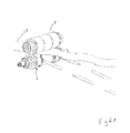
- FIGs. 6A and 6B show schematically how a web 68 is conveyed via the nip 69 between the cutter drum 12 and the anvil drum 26, being in a cutting relationship, and how the cut articles are directed in another direction than what is the case for the residue of the web, and depending on which one of the drums is arranged on top of the other.
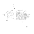
- Figure 7 shows schematically the principle of the mass damper 47 shown in figures 1B and 2 .
- an elongated circular cylindrical housing 48 is concentrically provided with a rod or a tubing 70.
- the housing is 48 connected to the rod or tubing 70 by means of a bushing 72, preferably made of an elastomeric material, such that disassembly is allowed.
- a space 74 is defined between the housing and the rod.
- a damping body 50 made of e.g. plastic, steel or led.
- the damping body 50 is substantially prevented from moving in an axial direction by the bushings 72.
- the damping body 50 is however allowed to move in a radial direction in relation to said rod or tubing 70 inside the housing 48.
- the remaining space is filled with a fluid, such as air, water, oil or grease.
- the mass damper 50 may instead be constituted by a liquid of high density, such as mercury.
- the damping body may be comprise granules of a suitable material such as led, optionally combined with a fluid (cf. above)
- the mass damper 47 is possible to tune for different frequency ranges by choosing the length and diameter of the damping body 50 or the number of mass dampers 47, by choosing material of the damping body and by choosing what kind of gas or liquid is filled in the remaining space inside the housing.
- Vibrations will be caused due to unbalances in the rotary cutter 6 and/or rotary anvil 8.
- the web 68 is in itself relatively uneven as seen in a transverse direction of the web 68. This is because the contents of the web itself is a a combination of layers of varying thickness of i.a. fibres and super-gel.
- a vertical movement of the rotary anvil 8 is caused. The larger the vertical movement, the larger the amplitude of the vibration. Due to the varying thickness of the web, continuous vibrations will be created when the web passes the nip 69.
- the springs 44 as such will add to the the stiffness of the frame and consequently move the eigenfrequencies to a desired frequency.
- a foreign body inside or on the web causes the rotary anvil 8 to move vertically away from the cutting relationship with the rotary cutter even more.
- the anvil drum 26 will be pressed towards the cutter drum 12 by the force of the pneumatic cylinders 38, possibly causing an impact.
- the springs 44 will reduce the return force of the impact, but they cannot reduce the vibrations due to the impact. For this reason, the passive dampers 46 as described above are provided.
- the passive dampers 46 in the form of elastomeric members 52 will instantaneously reduce the force of the impact due to the circular cylindrical shape, and the choice of material will add to the reduction of the vibrations caused by the impact.
- the elastic members have been shown as shorter than the axial elongation of the springs 44. They may however be longer than the helical springs.
- the passive dampers 46 in the form of one or more mass dampers 47 will not be able to reduce the impact as such, but tests have proven that they will very efficiently and quickly reduce the vibrations caused by impacts.
- the housing 48 of the mass damper 47 may have any suitable shape, the cylinder having a cross-section being e.g. square, rectangular, triangular, polygonal or oval, the damping body 50 being adapted to the selected shape. Furthermore, the housing may have a non-cylindrical shape.
- the pneumatic cylinders 38 may instead be hydraulic.
- the intermediate sleeve 22 shown in Fig 1A may be constitutes by a further cutter sleeve.
- the cutter sleeves 18a, 18b and the intermediate sleeve 22 may be constituted by a single cutter sleeve.
- the support rings 17 of the cutter drum 12 are described above as bearing against the support rings 27 of the anvil drum 26. It should however be noted that the anvil drum 26 may not be provided with support rings 27 at all, such that the support rings 17 of the cutter drum will bear directly against the anvil drum 26. Likewise, the cutter drum 12 may not be provided with the support rings 17 at all, such that the support rings of the anvil drum will bear directly against the cutter drum 12.
- the springs 44 have been shown in the figures as helical springs. It should however be understood that any kind of resilient means having a spring action is meant.
- the passive damper 46 in the form of four elastomeric members 52 may be made of any suitable damping material and may have any shape, such as cylindrical with a square shape or another polygonal shape. Likewise, the cylindrical shape may instead have the shape of a cone or a truncated cone or even spherical. It may be solid or hollow, depending on whether it is to be arranged about the spring 44 or beside it. The number is also not restricted to four, but could be two, three, or five or more, depending on the desired properties.
- the rotary anvil 8 is vertically movable in relation to the frame 4
- the rotary cutter 6 may instead be vertically movable in relation to the frame.
- the cutter bearing housings 14 of the cutter shaft 10 will be connected to the intermediate piece 32, movably arranged at the guide members 36, while the anvil bearing housings 30 of the anvil shaft 24 will be connected to the frame 4. This relates to the both the upper (see Figs.1A-1C , 2 and 3 ) and the lower arrangement (see Fig.5 ) of the intermediate piece 32.
- the anvil drum may be made in one piece together with the shaft.
Landscapes
- Life Sciences & Earth Sciences (AREA)
- Forests & Forestry (AREA)
- Engineering & Computer Science (AREA)
- Mechanical Engineering (AREA)
- Perforating, Stamping-Out Or Severing By Means Other Than Cutting (AREA)
- Manufacturing Of Cigar And Cigarette Tobacco (AREA)
Abstract
Description
- The present invention relates to a rotary cutting apparatus, comprising
- a frame;
- a first rotary device, such as a rotary cutter or a rotary anvil comprising a first shaft concentrically arranged about a first rotational axis and a first drum, such as an anvil drum or a cutter drum concentrically arranged on said first shaft , said first shaft being provided with a first pair of bearing housings arranged on either sides of said first drum;
- a second rotary device comprising a second shaft concentrically arranged about a second rotational axis, and a second drum, such as an anvil drum or a cutter drum concentrically arranged on said shaft, said second shaft being provided with a second pair of bearing housings arranged on either sides of said second drum;
- said first and second rotary devices being arranged in said frame in such a way that said first and second axes are substantially horizontal and substantially in the same vertical plane;
- said second shaft being connected to the frame via said second pair of bearing housings;
- said first shaft being associated with said frame via said first pair of bearing housing , said first pair of bearing housings being movable relative to said frame in a transverse direction to said first rotational axis by means of a force means.
- Such a rotary cutting apparatus is known from
EP-A-1 710 058 . The known rotary cutting apparatus however suffers from the drawback that it is not adapted for high speed cutting. -
EP-A-1 721 712 discloses a rotary cutting apparatus provided with a controllable lifting device for actively lifting the anvil in response to a sensor for sensing protection of the anvil and the cutter against foreign bodies. -
EP-A-1 612 010 discloses an anvil drum and the cutter drum for a rotary cutting apparatus, the anvil drum and/or the cutter drum being divided into a peripheral sleeve and and an intermediate sleeve, the material of the latter being chosen depending on the desired properties, such as vibration damping, thermal insulation, thermal conduction, weight reduction or weight increase. -
WO 03/093696 - An object of the present invention is to improve the stability of the first and the second arbours of the rotary cutting apparatus.
- This has been achieved by a rotary cutting apparatus as initially defined, wherein means is provided for passive vibration attenuation of at least said first shaft, said means being able to reduce vibrations due to impacts of the first drum in relation to said second drum.
- Hereby is achieved that the anvil drum and the cutter drum are better protected from impacts. Furthermore, due the rotary cutting apparatus can be used at higher speeds.
- Preferably, said first pair of bearing housings are connected to an intermediate piece slidingly arranged in relation to said frame via at least one guide member, wherein said force means comprises a pneumatic cylinder for pressing the first drum via said intermediate piece towards said second drum such that they come into a cutting relationship with one another, and at least one spring means for applying a force counter directed to that of the pneumatic cylinder, said means for vibration attenuation comprising at least one elastomeric member. Hereby is achieved a controlled movement of the first drum in relation to said second drum.
- Suitably, said spring means is a helical spring and said said elastomeric member is hollow, said elastomeric member being arranged substantially coaxially to said helical spring. Hereby, a compact design is achieved.
- Preferably, said frame is provided with a part having a substantial C-shaped cross-section on either sides of said first shaft, said part having an upper shank and a lower shank interconnected via an interconnecting portion, said guide member being arranged between said upper shank and said lower shank, said elastomeric member and said helical spring member being arranged substantially coaxially to said guide member. Hereby is achieved a controlled movement of the first drum in relation to said second drum as well as a compact design.
- Preferably, said elastomeric member has a circular cross-section. Hereby, the shape of the elastomeric member is optimal in relation to said helical spring.
- Suitably, said first rotary device comprises a rotary anvil and in that said second rotary device comprises a rotary cutter.
- In the following, preferred embodiments of the invention will be described in further detail with reference to the accompanying drawings, in which
-
Figure 1A is a front perspective view of a rotary cutting apparatus according to a first embodiment of the invention having cutter drum and an anvil drum; -
Figure 1B is a front perspective view of the rotary cutting apparatus shown inFig. 1A , including a mass damper, parts of the frame being omitted; -
Figure 1C is a rear perspective view of the rotary cutting apparatus shown inFig. 1A , parts of the frame being omitted; -
Figure 2 is a front perspective view of a rotary cutting apparatus according to an alternative aspect of the invention including a mass damper; -
Figure 3 is a front perspective view of a rotary cutting apparatus according to a further aspect of the invention; -
Figure 4 is an anvil drum as shown inFigs. 1A-1C andFigs. 2-3 , partly with details omitted, partly in cross-section -
Figure 5 is a front perspective view of a rotary cutting apparatus according to a further aspect of the invention; -
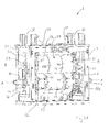
Figures 6a and6b is a schematic view of a web cut to articles by the cutting apparatus shown inFigs. 1 to 5 . -
Figure 7 illustrates schematically the principle of the mass damper shown infigures 1B and2 . -
Figs. 1A-1C show arotary cutting apparatus 2 comprising aframe 4 adapted to be attached to a not-shown basement. In theframe 4, arotary cutter 6 and arotary anvil 8 are arranged. InFig. 1A , therotary cutter 6 and therotary anvil 8 are shown in a cutting relationship, whereas inFigs. 1B and Fig. 1D, they are shown in a separated relationship. - The
rotary cutter 6 is provided with anelongated cutter shaft 10 and acutter drum 12, thecutter drum 12 being coaxially arranged on thecutter shaft 10 about a rotation axis A-A. The shaft has an axial extension on each side of thecutter drum 12, where acutter bearing housing 14 is provided, respectively. The cutter bearinghousings 14 are each connected to theframe 4 by means of a fastening element 16, such as a screw. Thecutter shaft 10 is preferably made of steel and is adapted to connected to a not shown rotatable power source. - The
cutter drum 12 is provided with a pair ofannular support rings 17 and a pair of annular cutter sleeves 18a, 18b each provided with cuttingmembers 20 for cutting articles from a web (seeFig 6 .). Thesupport rings 17 may be separate parts. Alternatively, one of the support rings may be an integrated part of the cutter sleeve 18a and the other support ring an integrated part of the other cutter sleeve 18b. An intermediateannular sleeve 22 without cutting edges is provided between the annular cutter regions 18a, 18b, theintermediate sleeve 22 and the cutter sleeve 18a, 18b being coaxially arranged in relation to the axis A-A. Alternatively, thesupport rings 17, the annular cutting sleeves 18a, 18b and the intermediateannular sleeve 22 may be made of one single piece, forming a an integrated annular sleeve, the axial extension of which corresponding to that of thecutter drum 12. - The
support rings 17, the annular cutter sleeves 18a, 18b and/or the intermediate piece may be made of steel, but are preferably made of a cemented carbide. They are press-fit onto a portion of thecutter shaft 10 having an enlarged diameter, altogether constituting saidcutter drum 12. - The
rotary anvil 8 is provided with anelongated anvil shaft 24 and ananvil drum 26, theanvil drum 26 being coaxially arranged on theanvil shaft 24 about a rotation axis B-B. - The
anvil drum 26 comprises a pair ofsupport rings 27 and three coaxially arranged annular anvil sleeves 28a, 28b, 28c, each having a rotationalsymmetrical anvil surface 29, coaxial to the axis B-B. - The
support rings 27 may be separate parts. Alternatively, one of the support rings may be an integrated part of the peripheral anvil sleeve 28a and the other support ring an integrated part of the other peripheral anvil sleeve 28c. The peripheral anvil sleeves 28a, 28c are arranged on either sides of the anvil sleeve 28b. Together, they are coaxially arranged in relation to the rotational axis B-B and are preferably made of steel. Alternatively, the peripheral sleeves 28a, 28c, the intermediate sleeve 28b and the support rings 27 are made as a single piece, forming an integrated annular sleeve, the axial extension of which corresponding to that of the cutterdrum anvil drum 26. - They are press-fit onto a portion of the
anvil shaft 24 having an enlarged diameter, altogether constituting said anvil drum 26 (see alsoFig. 4 ). - The support rings 27 are adapted to bear against the support rings 17 of the cutter drum during the cutting operation.
- The
anvil shaft 24 is arranged vertically above thecutter shaft 10 in such a way that the axis B-B is parallel to and is in the same vertical plane as the axis A-A. - An
anvil bearing housing 30 is arranged on either sides of theanvil drum 26 and connected to an intermediate piece 32 (best shown inFig. 1B ). Theintermediate piece 32 is in sliding relationship with a pair of C-shapedparts 34 of theframe 4, having an upper shank 34a, a lower shank 34b and an interconnecting portion 34c, via fourguide members 36. The C-shapedpart 34 is provided with an opening 37 for allowing access to theanvil bearing housing 30, two of theguide members 36 being arranged between the upper and lower shanks 34a, 34b and on opposite sides of one of theanvil bearing housings 30, while two further guide members are arranged between the upper and lower shanks 34a, 34b and on opposite sides of the otheranvil bearing housing 30. - A pair of
pneumatic cylinders 38 are each provided with a piston 40 (best shown inFig. 1C ) and ahose 42 for connection to a not shown pneumatic source. During operation, the piston will press theintermediate piece 32 including theanvil bearing housings 30 and thus also theanvil support ring 27 as well as the surface of the annular anvil rings 28a, 28c towards and against the support rings 17 and the cuttingmembers 20 of the cutter drum, respectively. - A
helical spring 44 is provided about eachguide member 36 and acting on theintermediate piece 32 and the 34b lower shank of the C-shapedpart 34. Hereby, theanvil drum 26 is prevented from colliding with thecutter drum 12 when applying pressure by means of the pneumatic cylinders or after passage of a foreign body, in turn avoiding damages of theknife member 20 and/or theanvil surface 29. Thesprings 44 also counter-balance the weight of therotary anvil 8, such that a minimum pressure is required for theanvil surface 29 to come into contact with the cuttingmembers 20 during use. - Between the
intermediate piece 32 on each side of theanvil drum 26, apassive damper 46 in the form of amass damper 47 comprising anelongated cylinder 48 is arranged parallel to the rotational axis B-B of theanvil drum 26. Thecylinder 48 is connected to theintermediate pieces 32 bybrackets 49, respectively. Theelongated cylinder 48 comprises a movable damping body 50, tunable to a predetermined frequency range. - A further
passive damper 46 in the form of themembers 52 shown as circular-cylindrical tubes and made of any elastomeric material having a high damping coefficient, such as polyurethane (PU), rubber, silicone or neoprene. Each elastomeric member is are arranged about one of thehelical springs 44 and thus also about one of theguide members 36, as can be understood by the cross-section-in-part ofFig. 1B . - The
elastomeric members 52 also adds to the stiffness of therotary cutting apparatus 2, adding to the stability of thereof. - The
elastomeric members 52 will isolate theanvil drum 26 from the vibrations transferred via the frame from the web or the source of power. - As already mentioned above,
Fig. 1A shows how therotary cutter 6 and therotary anvil 8 come into a cutting relationship by allowing thepneumatic cylinders 38 to press against anupper contact surface 54 of the intermediate piece and in turn on the rotary anvil. - In
Figs 1B . and1C thepneumatic cylinders 38 have been de-activated, such that no pressure is any longer exerted by them downwardly on theintermediate pieces 32. Instead, thesprings 44 exert a pressure upwardly on the lower shank 34b of the C-shapedportion 34 and on alower contact surface 56 of theintermediate piece 32. Thesprings 44 will thus cause therotary anvil 8 to move vertically upwards and away from therotary cutter 6 to the above mentioned non-cutting, in this case lifted position. - When the
anvil drum 26 is in a cutting relationship with thecutter drum 12, the elastomeric members 52 (seeFig. 1B ) will each contact the lower shank 34b of the C-shapedparts 34 as well as thelower contact surface 56 of theintermediate piece 32. However, when thepneumatic cylinders 38 are inactivated, thesprings 44 will press theintermediate piece 32 vertically upwards such that theupper contact surface 54 of theintermediate piece 32 will rest against the upper shank 34a of the C-shapedpart 34. There will be a free space between theelastomeric member 52 and thelower contact surface 56 of the intermediate piece, since theelastomeric member 52 has a shorter axial extension than thespring 44. - In order to lower the centre of gravity, the
intermediate piece 32 is made of a light material, such as aluminium. Also other parts arranged at a high point influencing the centre of gravity should be made of a light material, such that it can be lowered. - In
Fig. 1C is also shown aguide roller 60 for a web 68 (see alsoFig. 6 ), as well asmoisturising rollers 62 for applying oil on the cuttingmembers 20. -
Figure 2 shows a second embodiment of the invention, according to which a pair ofpassive dampers 46 in the form ofelongated cylinders 48 are connected to eachintermediate piece 32 byretainers 61. The elongation of thecylinders 48 are in this case across the rotational axis B-B of said anvil. - Also in this case, the
elongated cylinders 48 aremass dampers 47. No further passive damper in the form of circular-cylindrical rings is provided. - As described above, the
springs 44 act in cooperation with thepneumatic cylinders 38. As can be seen inFig. 2 , theanvil drum 26 is in its non-cutting, also in this case lifted position. - Depending on the vibration damping requirements, the
mass dampers 47 ofFigure 2 could be combined with further passive dampers in the form ofelastomeric rings 44 as shown infigures 1A-1C . -
Figure 3 shows a third embodiment, according to which passive dampers in the form of elastomeric rings are provided about the springs. The springs are visible, sine theanvil drum 26 is in its non-cutting, also in this case lifted position. No mass damper is provided. -
Figure 4 shows therotary anvil 26 ofFigs. 1A-1C ,2 and3 with itsanvil shaft 24 and anvil sleeves 28a, 28b, 28c (the anvil sleeve 28a being omitted in the figure for facilitating understanding). - In order to reduce vibrations in the
rotary cutting apparatus 38, it is preferred that the centre of gravity of therotary cutting apparatus 2 is as low as possible. - As can bee seen in the figure, the anvil shaft has a larger radial extension than that of the opposite ends, where the bearing housings are to be arranged. Consequently, in order to reduce weight of the rotary anvil mounted above the
rotary cutter 6, radialblind holes 64 are provided in theanvil shaft 24 under the anvil sleeves 28a, 28c. For the same purpose, a ring-shapedgroove 66 is provided underneath the anvil sleeve 28b, hereby reducing of the diameter of theanvil shaft 24. It should be noted that the radialblind holes 64 and/or the groove should be large enough to create a substantial weight reduction. - It should be noted that the centre of gravity may be lowered by choice of material of relatively heavy parts, e.g. of the
intermediate part 32 shown inFigs. 1A-1C and2-3 , to aluminium, carbon fibre or the like, instead of steel. -
Figure 5 shows a fourth embodiment, according to which therotary cutter 6 withknife members 20 is arranged vertically above therotary anvil 8. As described above, theanvil shaft 24 is connected via theanvil bearing housings 30 to theintermediate piece 32, which is movably arranged in relation to guidemembers 36. Thepneumatic cylinders 38 are arranged below therotary anvil 8 and thus press theanvil drum 26 upwards towards and against thecutter drum 12 to a cutting position. When thepneumatic cylinders 38 are inactivated, the springs will press theanvil drum 26 downwards to a non-cutting, in this case lowered position (not shown). - In order to lower the centre of gravity, the extension of the
cutter shaft 10 may be reduced such that it does not extend outside one of thecutter bearing housing 14, the other extension being connected to a not shown power source. - In this embodiment, the
cutter shaft 10 may instead of theanvil shaft 24 be provided with the weight reduction as explained in connection withFig. 4 , since this will lower the centre of gravity of therotary cutting apparatus 2. Preferably, theintermediate piece 32 should in this case be made of steel, since the low position of it would in itself lower the centre of gravity. - In
Fig 6A , theanvil drum 26 is arranged above thecutter drum 12, whereas inFig. 6B , the cutter drum is arranged above the anvil drum.Figs. 6A and6B show schematically how aweb 68 is conveyed via the nip 69 between thecutter drum 12 and theanvil drum 26, being in a cutting relationship, and how the cut articles are directed in another direction than what is the case for the residue of the web, and depending on which one of the drums is arranged on top of the other. -
Figure 7 shows schematically the principle of themass damper 47 shown infigures 1B and2 . - In the
mass damper 47 ofFig. 7 , an elongated circularcylindrical housing 48 is concentrically provided with a rod or a tubing 70. The housing is 48 connected to the rod or tubing 70 by means of abushing 72, preferably made of an elastomeric material, such that disassembly is allowed. Aspace 74 is defined between the housing and the rod. In the space, there is provided a damping body 50 made of e.g. plastic, steel or led. The damping body 50 is substantially prevented from moving in an axial direction by thebushings 72. The damping body 50 is however allowed to move in a radial direction in relation to said rod or tubing 70 inside thehousing 48. The remaining space is filled with a fluid, such as air, water, oil or grease. - The mass damper 50 may instead be constituted by a liquid of high density, such as mercury. Alternatively, the damping body may be comprise granules of a suitable material such as led, optionally combined with a fluid (cf. above)
- The
mass damper 47 is possible to tune for different frequency ranges by choosing the length and diameter of the damping body 50 or the number ofmass dampers 47, by choosing material of the damping body and by choosing what kind of gas or liquid is filled in the remaining space inside the housing. - A cutting operation as shown in
Figs. 6A and6B has commenced. - Vibrations will be caused due to unbalances in the
rotary cutter 6 and/orrotary anvil 8. - The
web 68, is in itself relatively uneven as seen in a transverse direction of theweb 68. This is because the contents of the web itself is a a combination of layers of varying thickness of i.a. fibres and super-gel. When passing the nip 69, a vertical movement of therotary anvil 8 is caused. The larger the vertical movement, the larger the amplitude of the vibration. Due to the varying thickness of the web, continuous vibrations will be created when the web passes the nip 69. - In order to reduce the influence of continuous vibrations, it is important to lower the static and dynamic response and in particular to raise or lower the eigenfrequency by a proper design of the
rotary cutting apparatus 2 including theframe 4, e.g. by choice of dimensions and material of different parts. - The
springs 44 as such will add to the the stiffness of the frame and consequently move the eigenfrequencies to a desired frequency. - Continuous vibrations will be possible to reduce by lowering the centre of gravity of the rotary cutting apparatus, e.g. as discussed in connection with
Fig. 4 . - A foreign body inside or on the web causes the
rotary anvil 8 to move vertically away from the cutting relationship with the rotary cutter even more. When the foreign body has passed the nip 69, theanvil drum 26 will be pressed towards thecutter drum 12 by the force of thepneumatic cylinders 38, possibly causing an impact. Thesprings 44 will reduce the return force of the impact, but they cannot reduce the vibrations due to the impact. For this reason, thepassive dampers 46 as described above are provided. - The
passive dampers 46 in the form ofelastomeric members 52 will instantaneously reduce the force of the impact due to the circular cylindrical shape, and the choice of material will add to the reduction of the vibrations caused by the impact. - In the figures the elastic members have been shown as shorter than the axial elongation of the
springs 44. They may however be longer than the helical springs. - The
passive dampers 46 in the form of one or moremass dampers 47 will not be able to reduce the impact as such, but tests have proven that they will very efficiently and quickly reduce the vibrations caused by impacts. - The claims are not restricted to the embodiments shown above. Accordingly, depending on the vibration damping requirements, the mass dampers and of
Figure 2 could be combined with further dampers in the form of elastomeric rings as shown infigures 1A-1C . For the same reason, the elastomeric rings shown inFigs. 1A - 1C may be omitted. - The
housing 48 of themass damper 47 may have any suitable shape, the cylinder having a cross-section being e.g. square, rectangular, triangular, polygonal or oval, the damping body 50 being adapted to the selected shape. Furthermore, the housing may have a non-cylindrical shape. - Likewise, even though the
mass damper 47 ofFig. 5 has been shown as being solely of the cylindrical kind arranged parallel to the rotational axis B-B of the anvil drum, it could be replaced by themass dampers 47 across the rotational axis B-B, as shown inFig. 2 , be exchanged to the elastometric rings as shown inFig. 3 or be constituted by a combination of the dampers, depending on the damping requirements. - The
pneumatic cylinders 38 may instead be hydraulic. Theintermediate sleeve 22 shown inFig 1A may be constitutes by a further cutter sleeve. On the other hand, the cutter sleeves 18a, 18b and theintermediate sleeve 22 may be constituted by a single cutter sleeve. - The support rings 17 of the
cutter drum 12 are described above as bearing against the support rings 27 of theanvil drum 26. It should however be noted that theanvil drum 26 may not be provided with support rings 27 at all, such that the support rings 17 of the cutter drum will bear directly against theanvil drum 26. Likewise, thecutter drum 12 may not be provided with the support rings 17 at all, such that the support rings of the anvil drum will bear directly against thecutter drum 12. - The
springs 44 have been shown in the figures as helical springs. It should however be understood that any kind of resilient means having a spring action is meant. - The
passive damper 46 in the form of fourelastomeric members 52 may be made of any suitable damping material and may have any shape, such as cylindrical with a square shape or another polygonal shape. Likewise, the cylindrical shape may instead have the shape of a cone or a truncated cone or even spherical. It may be solid or hollow, depending on whether it is to be arranged about thespring 44 or beside it. The number is also not restricted to four, but could be two, three, or five or more, depending on the desired properties. - Even though it has been described above that the
rotary anvil 8 is vertically movable in relation to theframe 4, it should be understood that therotary cutter 6 may instead be vertically movable in relation to the frame. In that case, thecutter bearing housings 14 of thecutter shaft 10 will be connected to theintermediate piece 32, movably arranged at theguide members 36, while theanvil bearing housings 30 of theanvil shaft 24 will be connected to theframe 4. This relates to the both the upper (seeFigs.1A-1C ,2 and3 ) and the lower arrangement (seeFig.5 ) of theintermediate piece 32. - In the embodiment of
Figure 5 , where the anvil drum is arranged underneath the cutter drum, the anvil drum may be made in one piece together with the shaft. -
- 2 rotary cutting apparatus
- 4 frame
- 6 rotary cutter
- 8 rotary anvil
- 10 cutter shaft
- 12 cutter drum
- 14 cutter bearing housings
- 16 fastening element
- 17 support ring
- 18a, 18b annular cutter sleeve
- 20 cutting members
- 22 intermediate annular sleeve
- 24 anvil shaft
- 26 anvil drum
- 27 support rings
- 28a, 28b, 28c annular anvil sleeve
- 29 anvil surface
- 30 anvil bearing housing
- 32 intermediate piece
- 34 C-shaped part
- 34a upper shank
- 34b lower shank
- 34c interconnecting portion
- 36 guide member
- 37 opening
- 38 pneumatic cylinder
- 40 piston
- 42 hose
- 44 spring
- 46 passive damper
- 47 mass damper
- 48 elongated cylinder
- 49 bracket
- 50 damping body
- 52 elastomeric member
- 54 upper contact surface
- 56 lower contact surface
- 60 guide roller
- 61 retainer
- 62 moisturising roller
- 64 radial bore
- 66 groove
- 68 web
- 69 nip
- 70 rod or tubing
- 72 bushing
- 74 space
Claims (6)
- A rotary cutting apparatus, comprising- a frame (4);- a first rotary device, such as a rotary cutter (6) or a rotary anvil (8), comprising a first shaft (10 or 24) concentrically arranged about a first rotational axis (A-A or B-B) and a first drum (12 or 26), such as an anvil drum (26) or a cutter drum (12) concentrically arranged on said first shaft , said first shaft (10 or 24) being provided with a first pair of bearing housings (14 or 30) arranged on either sides of said first drum (12 or 26);- a second rotary device comprising a second shaft (10 or 24) concentrically arranged about a second rotational axis (A-A or B-B), and a second drum (12 or 26), such as an anvil drum (26) or a cutter drum (12) concentrically arranged on said shaft (10 or 24), said second shaft being provided with a second pair of bearing housings (14 or 30) arranged on either sides of said second drum (12 or 26);- said first and second rotary devices being arranged in said frame (4) in such a way that said first and second axes (A-A, B-B)are substantially horizontal and substantially in the same vertical plane;- said second shaft (10 or 24) being connected to the frame (4) via said second pair of bearing housings (14 or 30);- said first shaft (10 or 24) being associated with said frame (4) via said first pair of bearing housing (14 or 30), said first pair of bearing housings being movable relative to said frame (4) in a transverse direction to said first rotational axis (A-A or B-B) by means of a force means (38), characterised in that means (46) is provided for passive vibration attenuation of at least said first shaft (10 or 24), said means (46) being able to reduce vibrations due to impacts of the first drum (12 or 26) in relation to said second drum (12 or 26).
- A rotary cutting device according to claim 1, wherein said first pair of bearing housings (14 or 30) are connected to an intermediate piece (32) slidingly arranged in relation to said frame (4) via at least one guide member (36), wherein said force means comprises a pneumatic cylinder (38) for pressing the first drum (12 or 26) via said intermediate piece (32) towards said second drum (12 or 26) such that they come into a cutting relationship with one another, and at least one spring means (44) for applying a force counter directed to that of the pneumatic cylinder (38), said means for vibration attenuation comprising at least one elastomeric member (52).
- A rotary cutting device according to claim 2, wherein said spring means (44) is a helical spring and said said elastomeric member (54) is hollow, said elastomeric member (44) being arranged substantially coaxially to said helical spring (44)
- A rotary cutting apparatus according to claim 3, wherein said frame (4) is provided with a part (34) having a substantial C-shaped cross-section on either sides of said first shaft (10 or 24), said part (34) having an upper shank (34a) and a lower shank (34b) interconnected via an interconnecting portion (34c), said guide member (36) being arranged between said upper shank (34a) and said lower shank (34b), said elastomeric member (54) and said helical spring member being arranged substantially coaxially to said guide member (36).
- A rotary cutting apparatus according to claim 4, wherein said elastomeric member has a circular cross-section.
- A rotary cutting apparatus according to any one of the preceding claims, wherein said first rotary device comprises a rotary anvil (8) and in that said second rotary device comprises a rotary cutter (6).
Applications Claiming Priority (1)
| Application Number | Priority Date | Filing Date | Title |
|---|---|---|---|
| SE1150312A SE536116C2 (en) | 2011-04-08 | 2011-04-08 | Rotary cutting apparatus with vibration damping means |
Publications (2)
| Publication Number | Publication Date |
|---|---|
| EP2508311A1 true EP2508311A1 (en) | 2012-10-10 |
| EP2508311B1 EP2508311B1 (en) | 2018-05-30 |
Family
ID=45930597
Family Applications (1)
| Application Number | Title | Priority Date | Filing Date |
|---|---|---|---|
| EP12160764.2A Active EP2508311B1 (en) | 2011-04-08 | 2012-03-22 | A rotary cutting apparatus with vibration attenuation means |
Country Status (8)
| Country | Link |
|---|---|
| US (1) | US8739667B2 (en) |
| EP (1) | EP2508311B1 (en) |
| JP (1) | JP6079983B2 (en) |
| CN (1) | CN102729284B (en) |
| BR (1) | BR102012008196B1 (en) |
| ES (1) | ES2677097T3 (en) |
| SE (1) | SE536116C2 (en) |
| TR (1) | TR201808030T4 (en) |
Cited By (1)
| Publication number | Priority date | Publication date | Assignee | Title |
|---|---|---|---|---|
| EP3153285A1 (en) | 2015-10-06 | 2017-04-12 | Sandvik Intellectual Property AB | A rotary cutting apparatus with an embedded monitoring unit |
Families Citing this family (10)
| Publication number | Priority date | Publication date | Assignee | Title |
|---|---|---|---|---|
| SE536116C2 (en) * | 2011-04-08 | 2013-05-14 | Sandvik Intellectual Property | Rotary cutting apparatus with vibration damping means |
| SE536109C2 (en) * | 2011-04-08 | 2013-05-07 | Sandvik Intellectual Property | Rotary cutting apparatus with vibration damping means |
| US10059015B2 (en) * | 2012-10-23 | 2018-08-28 | The Procter & Gamble Company | Method and apparatus for positioning a cutting apparatus |
| CN103802153B (en) * | 2012-11-09 | 2015-12-23 | 安庆市恒昌机械制造有限责任公司 | Arc on disposable sanitary articles production line cuts assembly apparatus |
| JP6403304B2 (en) * | 2013-10-17 | 2018-10-10 | 株式会社瑞光 | Rotary cutter |
| CN106255577B (en) * | 2014-04-03 | 2018-08-31 | 山特维克知识产权股份有限公司 | High-performance rotary cutting apparatus for the profile with straight edge |
| BR112017001103A2 (en) * | 2014-07-22 | 2017-11-14 | Sandvik Intellectual Property | fabricated anvil for rotary cutting unit additive |
| CN105150262A (en) * | 2015-08-26 | 2015-12-16 | 安庆市兴丰工贸有限公司 | Novel cutting structure of slitter |
| JP7403021B1 (en) | 2023-04-24 | 2023-12-21 | 日本タングステン株式会社 | rotary cutter unit |
| CN117737990B (en) * | 2023-12-19 | 2025-12-05 | 浙江东方星月地毯产业有限公司 | A carpet manufacturing adhesive coating and laminating device |
Citations (4)
| Publication number | Priority date | Publication date | Assignee | Title |
|---|---|---|---|---|
| WO2003093696A2 (en) | 2002-04-30 | 2003-11-13 | Teeness As | Damping apparatus for the damping of vibrations |
| EP1612010A1 (en) | 2004-07-02 | 2006-01-04 | Sandvik Intellectual Property AB | Rotary cutter and anvil roll for rotary cutting apparatus |
| EP1710058A1 (en) | 2005-04-07 | 2006-10-11 | Sandvik Intellectual Property AB | A rotary cutting apparatus comprising a cutter drum and anvil drum |
| EP1721712A1 (en) | 2005-05-11 | 2006-11-15 | Aichele Werkzeuge GmbH | Rotary cutting device, method of disabling a rotary cutting device and method of operating a rotary cutting device |
Family Cites Families (12)
| Publication number | Priority date | Publication date | Assignee | Title |
|---|---|---|---|---|
| US661470A (en) * | 1900-05-22 | 1900-11-06 | Joseph Fawell | Rolling-mill. |
| JPS6034548A (en) * | 1983-08-04 | 1985-02-22 | Matsushita Electric Ind Co Ltd | Vibration isolator |
| JPS6154355A (en) * | 1984-08-20 | 1986-03-18 | ボンバーディア・コーポレーション | Vibration-damping means for mechanical spring in railway rolling stock |
| US5048387A (en) * | 1989-07-14 | 1991-09-17 | Komori Corporation | Horizontal perforation forming apparatus for rotary press |
| US5176610A (en) * | 1991-05-13 | 1993-01-05 | Custom Machinery Design, Inc. | Fly-knife dampening system |
| DE19746528A1 (en) * | 1997-10-22 | 1999-04-29 | Schloemann Siemag Ag | High-speed shears for cross cutting of rolled strip |
| US6435069B1 (en) * | 1999-11-23 | 2002-08-20 | Iam Corporation | Rotary die cutting cover |
| US7299729B2 (en) * | 2001-05-23 | 2007-11-27 | Cox William A | Rotary die module |
| SE530688C2 (en) * | 2005-04-07 | 2008-08-12 | Sandvik Intellectual Property | A rotatable cutting device comprising a cutting roller and a supporting roller |
| SE536109C2 (en) * | 2011-04-08 | 2013-05-07 | Sandvik Intellectual Property | Rotary cutting apparatus with vibration damping means |
| SE536116C2 (en) * | 2011-04-08 | 2013-05-14 | Sandvik Intellectual Property | Rotary cutting apparatus with vibration damping means |
| US9067335B2 (en) * | 2012-08-08 | 2015-06-30 | Container Graphics Corporation | Resilient finger scrap stripper for corrugated board rotary cutting die |
-
2011
- 2011-04-08 SE SE1150312A patent/SE536116C2/en unknown
-
2012
- 2012-03-22 ES ES12160764.2T patent/ES2677097T3/en active Active
- 2012-03-22 EP EP12160764.2A patent/EP2508311B1/en active Active
- 2012-03-22 TR TR2018/08030T patent/TR201808030T4/en unknown
- 2012-03-27 US US13/431,167 patent/US8739667B2/en active Active
- 2012-04-06 JP JP2012087288A patent/JP6079983B2/en active Active
- 2012-04-09 CN CN201210102335.5A patent/CN102729284B/en active Active
- 2012-04-09 BR BR102012008196-2A patent/BR102012008196B1/en active IP Right Grant
Patent Citations (4)
| Publication number | Priority date | Publication date | Assignee | Title |
|---|---|---|---|---|
| WO2003093696A2 (en) | 2002-04-30 | 2003-11-13 | Teeness As | Damping apparatus for the damping of vibrations |
| EP1612010A1 (en) | 2004-07-02 | 2006-01-04 | Sandvik Intellectual Property AB | Rotary cutter and anvil roll for rotary cutting apparatus |
| EP1710058A1 (en) | 2005-04-07 | 2006-10-11 | Sandvik Intellectual Property AB | A rotary cutting apparatus comprising a cutter drum and anvil drum |
| EP1721712A1 (en) | 2005-05-11 | 2006-11-15 | Aichele Werkzeuge GmbH | Rotary cutting device, method of disabling a rotary cutting device and method of operating a rotary cutting device |
Cited By (4)
| Publication number | Priority date | Publication date | Assignee | Title |
|---|---|---|---|---|
| EP3153285A1 (en) | 2015-10-06 | 2017-04-12 | Sandvik Intellectual Property AB | A rotary cutting apparatus with an embedded monitoring unit |
| WO2017060196A1 (en) * | 2015-10-06 | 2017-04-13 | Sandvik Intellectual Property Ab | A rotary cutting apparatus with an embedded monitoring unit |
| CN108025449A (en) * | 2015-10-06 | 2018-05-11 | 山特维克知识产权股份有限公司 | Rotary cutting equipment with embedded monitoring unit |
| US10695930B2 (en) | 2015-10-06 | 2020-06-30 | Hyperion Materials & Technologies (Sweden) Ab | Rotary cutting apparatus with an embedded monitoring unit |
Also Published As
| Publication number | Publication date |
|---|---|
| EP2508311B1 (en) | 2018-05-30 |
| BR102012008196A2 (en) | 2013-06-11 |
| CN102729284B (en) | 2016-08-03 |
| US8739667B2 (en) | 2014-06-03 |
| TR201808030T4 (en) | 2018-06-21 |
| US20120255411A1 (en) | 2012-10-11 |
| SE1150312A1 (en) | 2012-10-09 |
| JP6079983B2 (en) | 2017-02-15 |
| SE536116C2 (en) | 2013-05-14 |
| JP2012218149A (en) | 2012-11-12 |
| BR102012008196B1 (en) | 2021-04-20 |
| CN102729284A (en) | 2012-10-17 |
| ES2677097T3 (en) | 2018-07-30 |
Similar Documents
| Publication | Publication Date | Title |
|---|---|---|
| EP2508311B1 (en) | A rotary cutting apparatus with vibration attenuation means | |
| EP2508312B1 (en) | A rotary cutting apparatus with vibration attenuation means | |
| EP2777815B1 (en) | Crusher belt tensioning apparatus | |
| CN204728993U (en) | A kind of rotary digging drill power head buffer | |
| KR200479122Y1 (en) | Apparatus for supporting rotation of pipe | |
| CN110985594B (en) | A multi-pivot shafting vibration suppression device | |
| KR200441210Y1 (en) | apparatus for cutting plate shaped plastic foam | |
| EP1710058A1 (en) | A rotary cutting apparatus comprising a cutter drum and anvil drum | |
| CN209178806U (en) | A bridge shock-absorbing support that is easy to install and disassemble | |
| US20020084113A1 (en) | Apparatus for counterbalancing weight | |
| EP2910804A1 (en) | Linear guide system with overload protection | |
| JP2022522380A (en) | Roller lever module | |
| CN205309301U (en) | Shock insulation type lathe | |
| CN203370840U (en) | Wire feeding machine | |
| KR101828694B1 (en) | Hold down device of shearing apparatus | |
| EP2315659B1 (en) | Roller for the treatment of paper web material | |
| Pochekueva et al. | Analysis of vibration protection devices designed to protect the human operator of the earthmoving transport machine from dynamic influences | |
| CN223557272U (en) | Machining center spindle structure capable of reducing vibration | |
| JP4952701B2 (en) | Spring unit | |
| CN217971065U (en) | Multilateral damping roller way | |
| CZ32099U1 (en) | A fluid tunable passive dynamic vibration absorber |
Legal Events
| Date | Code | Title | Description |
|---|---|---|---|
| PUAI | Public reference made under article 153(3) epc to a published international application that has entered the european phase |
Free format text: ORIGINAL CODE: 0009012 |
|
| 17P | Request for examination filed |
Effective date: 20120322 |
|
| AK | Designated contracting states |
Kind code of ref document: A1 Designated state(s): AL AT BE BG CH CY CZ DE DK EE ES FI FR GB GR HR HU IE IS IT LI LT LU LV MC MK MT NL NO PL PT RO RS SE SI SK SM TR |
|
| AX | Request for extension of the european patent |
Extension state: BA ME |
|
| RIC1 | Information provided on ipc code assigned before grant |
Ipc: B26D 1/40 20060101AFI20171025BHEP Ipc: B26F 1/38 20060101ALI20171025BHEP Ipc: B26D 3/10 20060101ALN20171025BHEP Ipc: B26D 3/14 20060101ALI20171025BHEP Ipc: B26D 7/26 20060101ALI20171025BHEP |
|
| GRAP | Despatch of communication of intention to grant a patent |
Free format text: ORIGINAL CODE: EPIDOSNIGR1 |
|
| STAA | Information on the status of an ep patent application or granted ep patent |
Free format text: STATUS: GRANT OF PATENT IS INTENDED |
|
| INTG | Intention to grant announced |
Effective date: 20171221 |
|
| RIC1 | Information provided on ipc code assigned before grant |
Ipc: B26F 1/38 20060101ALI20171212BHEP Ipc: B26D 3/14 20060101ALI20171212BHEP Ipc: B26D 3/10 20060101ALN20171212BHEP Ipc: B26D 1/40 20060101AFI20171212BHEP Ipc: B26D 7/26 20060101ALI20171212BHEP |
|
| GRAJ | Information related to disapproval of communication of intention to grant by the applicant or resumption of examination proceedings by the epo deleted |
Free format text: ORIGINAL CODE: EPIDOSDIGR1 |
|
| GRAL | Information related to payment of fee for publishing/printing deleted |
Free format text: ORIGINAL CODE: EPIDOSDIGR3 |
|
| GRAS | Grant fee paid |
Free format text: ORIGINAL CODE: EPIDOSNIGR3 |
|
| STAA | Information on the status of an ep patent application or granted ep patent |
Free format text: STATUS: EXAMINATION IS IN PROGRESS |
|
| GRAR | Information related to intention to grant a patent recorded |
Free format text: ORIGINAL CODE: EPIDOSNIGR71 |
|
| STAA | Information on the status of an ep patent application or granted ep patent |
Free format text: STATUS: GRANT OF PATENT IS INTENDED |
|
| INTC | Intention to grant announced (deleted) | ||
| GRAA | (expected) grant |
Free format text: ORIGINAL CODE: 0009210 |
|
| STAA | Information on the status of an ep patent application or granted ep patent |
Free format text: STATUS: THE PATENT HAS BEEN GRANTED |
|
| RIC1 | Information provided on ipc code assigned before grant |
Ipc: B26D 3/14 20060101ALI20180323BHEP Ipc: B26F 1/38 20060101ALI20180323BHEP Ipc: B26D 7/26 20060101ALI20180323BHEP Ipc: B26D 3/10 20060101ALN20180323BHEP Ipc: B26D 1/40 20060101AFI20180323BHEP |
|
| INTG | Intention to grant announced |
Effective date: 20180417 |
|
| AK | Designated contracting states |
Kind code of ref document: B1 Designated state(s): AL AT BE BG CH CY CZ DE DK EE ES FI FR GB GR HR HU IE IS IT LI LT LU LV MC MK MT NL NO PL PT RO RS SE SI SK SM TR |
|
| REG | Reference to a national code |
Ref country code: GB Ref legal event code: FG4D |
|
| REG | Reference to a national code |
Ref country code: CH Ref legal event code: EP |
|
| REG | Reference to a national code |
Ref country code: AT Ref legal event code: REF Ref document number: 1003138 Country of ref document: AT Kind code of ref document: T Effective date: 20180615 |
|
| REG | Reference to a national code |
Ref country code: DE Ref legal event code: R096 Ref document number: 602012046793 Country of ref document: DE |
|
| REG | Reference to a national code |
Ref country code: IE Ref legal event code: FG4D |
|
| REG | Reference to a national code |
Ref country code: ES Ref legal event code: FG2A Ref document number: 2677097 Country of ref document: ES Kind code of ref document: T3 Effective date: 20180730 |
|
| REG | Reference to a national code |
Ref country code: NL Ref legal event code: MP Effective date: 20180530 |
|
| REG | Reference to a national code |
Ref country code: GB Ref legal event code: 732E Free format text: REGISTERED BETWEEN 20180913 AND 20180919 Ref country code: LT Ref legal event code: MG4D |
|
| PG25 | Lapsed in a contracting state [announced via postgrant information from national office to epo] |
Ref country code: FI Free format text: LAPSE BECAUSE OF FAILURE TO SUBMIT A TRANSLATION OF THE DESCRIPTION OR TO PAY THE FEE WITHIN THE PRESCRIBED TIME-LIMIT Effective date: 20180530 Ref country code: BG Free format text: LAPSE BECAUSE OF FAILURE TO SUBMIT A TRANSLATION OF THE DESCRIPTION OR TO PAY THE FEE WITHIN THE PRESCRIBED TIME-LIMIT Effective date: 20180830 Ref country code: NO Free format text: LAPSE BECAUSE OF FAILURE TO SUBMIT A TRANSLATION OF THE DESCRIPTION OR TO PAY THE FEE WITHIN THE PRESCRIBED TIME-LIMIT Effective date: 20180830 Ref country code: SE Free format text: LAPSE BECAUSE OF FAILURE TO SUBMIT A TRANSLATION OF THE DESCRIPTION OR TO PAY THE FEE WITHIN THE PRESCRIBED TIME-LIMIT Effective date: 20180530 Ref country code: LT Free format text: LAPSE BECAUSE OF FAILURE TO SUBMIT A TRANSLATION OF THE DESCRIPTION OR TO PAY THE FEE WITHIN THE PRESCRIBED TIME-LIMIT Effective date: 20180530 Ref country code: CY Free format text: LAPSE BECAUSE OF FAILURE TO SUBMIT A TRANSLATION OF THE DESCRIPTION OR TO PAY THE FEE WITHIN THE PRESCRIBED TIME-LIMIT Effective date: 20180530 |
|
| PG25 | Lapsed in a contracting state [announced via postgrant information from national office to epo] |
Ref country code: RS Free format text: LAPSE BECAUSE OF FAILURE TO SUBMIT A TRANSLATION OF THE DESCRIPTION OR TO PAY THE FEE WITHIN THE PRESCRIBED TIME-LIMIT Effective date: 20180530 Ref country code: HR Free format text: LAPSE BECAUSE OF FAILURE TO SUBMIT A TRANSLATION OF THE DESCRIPTION OR TO PAY THE FEE WITHIN THE PRESCRIBED TIME-LIMIT Effective date: 20180530 Ref country code: GR Free format text: LAPSE BECAUSE OF FAILURE TO SUBMIT A TRANSLATION OF THE DESCRIPTION OR TO PAY THE FEE WITHIN THE PRESCRIBED TIME-LIMIT Effective date: 20180831 Ref country code: LV Free format text: LAPSE BECAUSE OF FAILURE TO SUBMIT A TRANSLATION OF THE DESCRIPTION OR TO PAY THE FEE WITHIN THE PRESCRIBED TIME-LIMIT Effective date: 20180530 |
|
| REG | Reference to a national code |
Ref country code: DE Ref legal event code: R082 Ref document number: 602012046793 Country of ref document: DE Representative=s name: KRAUS & WEISERT PATENTANWAELTE PARTGMBB, DE Ref country code: DE Ref legal event code: R081 Ref document number: 602012046793 Country of ref document: DE Owner name: SANDVIK HYPERION AB, SE Free format text: FORMER OWNER: SANDVIK INTELLECTUAL PROPERTY AB, SANDVIKEN, SE Ref country code: DE Ref legal event code: R081 Ref document number: 602012046793 Country of ref document: DE Owner name: HYPERION MATERIALS & TECHNOLOGIES (SWEDEN) AB, SE Free format text: FORMER OWNER: SANDVIK INTELLECTUAL PROPERTY AB, SANDVIKEN, SE |
|
| PG25 | Lapsed in a contracting state [announced via postgrant information from national office to epo] |
Ref country code: NL Free format text: LAPSE BECAUSE OF FAILURE TO SUBMIT A TRANSLATION OF THE DESCRIPTION OR TO PAY THE FEE WITHIN THE PRESCRIBED TIME-LIMIT Effective date: 20180530 |
|
| REG | Reference to a national code |
Ref country code: LU Ref legal event code: PD Owner name: SANDVIK HYPERION AB; SE Free format text: FORMER OWNER: SANDVIK INTELLECTUAL PROPERTY AB Effective date: 20181128 |
|
| REG | Reference to a national code |
Ref country code: AT Ref legal event code: PC Ref document number: 1003138 Country of ref document: AT Kind code of ref document: T Owner name: SANDVIK HYPERION AB, SE Effective date: 20181121 |
|
| REG | Reference to a national code |
Ref country code: DE Ref legal event code: R081 Ref document number: 602012046793 Country of ref document: DE Owner name: HYPERION MATERIALS & TECHNOLOGIES (SWEDEN) AB, SE Free format text: FORMER OWNER: SANDVIK HYPERION AB, STOCKHOLM, SE Ref country code: DE Ref legal event code: R082 Ref document number: 602012046793 Country of ref document: DE Representative=s name: KRAUS & WEISERT PATENTANWAELTE PARTGMBB, DE |
|
| PG25 | Lapsed in a contracting state [announced via postgrant information from national office to epo] |
Ref country code: SK Free format text: LAPSE BECAUSE OF FAILURE TO SUBMIT A TRANSLATION OF THE DESCRIPTION OR TO PAY THE FEE WITHIN THE PRESCRIBED TIME-LIMIT Effective date: 20180530 Ref country code: RO Free format text: LAPSE BECAUSE OF FAILURE TO SUBMIT A TRANSLATION OF THE DESCRIPTION OR TO PAY THE FEE WITHIN THE PRESCRIBED TIME-LIMIT Effective date: 20180530 Ref country code: DK Free format text: LAPSE BECAUSE OF FAILURE TO SUBMIT A TRANSLATION OF THE DESCRIPTION OR TO PAY THE FEE WITHIN THE PRESCRIBED TIME-LIMIT Effective date: 20180530 Ref country code: EE Free format text: LAPSE BECAUSE OF FAILURE TO SUBMIT A TRANSLATION OF THE DESCRIPTION OR TO PAY THE FEE WITHIN THE PRESCRIBED TIME-LIMIT Effective date: 20180530 Ref country code: CZ Free format text: LAPSE BECAUSE OF FAILURE TO SUBMIT A TRANSLATION OF THE DESCRIPTION OR TO PAY THE FEE WITHIN THE PRESCRIBED TIME-LIMIT Effective date: 20180530 Ref country code: PL Free format text: LAPSE BECAUSE OF FAILURE TO SUBMIT A TRANSLATION OF THE DESCRIPTION OR TO PAY THE FEE WITHIN THE PRESCRIBED TIME-LIMIT Effective date: 20180530 |
|
| RAP2 | Party data changed (patent owner data changed or rights of a patent transferred) |
Owner name: SANDVIK HYPERION AB |
|
| PG25 | Lapsed in a contracting state [announced via postgrant information from national office to epo] |
Ref country code: SM Free format text: LAPSE BECAUSE OF FAILURE TO SUBMIT A TRANSLATION OF THE DESCRIPTION OR TO PAY THE FEE WITHIN THE PRESCRIBED TIME-LIMIT Effective date: 20180530 |
|
| REG | Reference to a national code |
Ref country code: DE Ref legal event code: R097 Ref document number: 602012046793 Country of ref document: DE |
|
| RAP2 | Party data changed (patent owner data changed or rights of a patent transferred) |
Owner name: HYPERION MATERIALS & TECHNOLOGIES (SWEDEN) AB |
|
| REG | Reference to a national code |
Ref country code: AT Ref legal event code: HC Ref document number: 1003138 Country of ref document: AT Kind code of ref document: T Owner name: HYPERION MATERIALS & TECHNOLOGIES (SWEDEN) AB, SE Effective date: 20190207 |
|
| PLBE | No opposition filed within time limit |
Free format text: ORIGINAL CODE: 0009261 |
|
| STAA | Information on the status of an ep patent application or granted ep patent |
Free format text: STATUS: NO OPPOSITION FILED WITHIN TIME LIMIT |
|
| 26N | No opposition filed |
Effective date: 20190301 |
|
| PG25 | Lapsed in a contracting state [announced via postgrant information from national office to epo] |
Ref country code: SI Free format text: LAPSE BECAUSE OF FAILURE TO SUBMIT A TRANSLATION OF THE DESCRIPTION OR TO PAY THE FEE WITHIN THE PRESCRIBED TIME-LIMIT Effective date: 20180530 |
|
| REG | Reference to a national code |
Ref country code: AT Ref legal event code: UEP Ref document number: 1003138 Country of ref document: AT Kind code of ref document: T Effective date: 20180530 |
|
| PG25 | Lapsed in a contracting state [announced via postgrant information from national office to epo] |
Ref country code: MC Free format text: LAPSE BECAUSE OF FAILURE TO SUBMIT A TRANSLATION OF THE DESCRIPTION OR TO PAY THE FEE WITHIN THE PRESCRIBED TIME-LIMIT Effective date: 20180530 |
|
| REG | Reference to a national code |
Ref country code: CH Ref legal event code: PL |
|
| PG25 | Lapsed in a contracting state [announced via postgrant information from national office to epo] |
Ref country code: AL Free format text: LAPSE BECAUSE OF FAILURE TO SUBMIT A TRANSLATION OF THE DESCRIPTION OR TO PAY THE FEE WITHIN THE PRESCRIBED TIME-LIMIT Effective date: 20180530 |
|
| REG | Reference to a national code |
Ref country code: BE Ref legal event code: MM Effective date: 20190331 |
|
| PG25 | Lapsed in a contracting state [announced via postgrant information from national office to epo] |
Ref country code: CH Free format text: LAPSE BECAUSE OF NON-PAYMENT OF DUE FEES Effective date: 20190331 Ref country code: LI Free format text: LAPSE BECAUSE OF NON-PAYMENT OF DUE FEES Effective date: 20190331 Ref country code: IE Free format text: LAPSE BECAUSE OF NON-PAYMENT OF DUE FEES Effective date: 20190322 |
|
| PG25 | Lapsed in a contracting state [announced via postgrant information from national office to epo] |
Ref country code: BE Free format text: LAPSE BECAUSE OF NON-PAYMENT OF DUE FEES Effective date: 20190331 |
|
| PG25 | Lapsed in a contracting state [announced via postgrant information from national office to epo] |
Ref country code: MT Free format text: LAPSE BECAUSE OF NON-PAYMENT OF DUE FEES Effective date: 20190322 Ref country code: PT Free format text: LAPSE BECAUSE OF FAILURE TO SUBMIT A TRANSLATION OF THE DESCRIPTION OR TO PAY THE FEE WITHIN THE PRESCRIBED TIME-LIMIT Effective date: 20181001 |
|
| PGFP | Annual fee paid to national office [announced via postgrant information from national office to epo] |
Ref country code: TR Payment date: 20200305 Year of fee payment: 9 |
|
| PG25 | Lapsed in a contracting state [announced via postgrant information from national office to epo] |
Ref country code: IS Free format text: LAPSE BECAUSE OF FAILURE TO SUBMIT A TRANSLATION OF THE DESCRIPTION OR TO PAY THE FEE WITHIN THE PRESCRIBED TIME-LIMIT Effective date: 20180930 |
|
| PG25 | Lapsed in a contracting state [announced via postgrant information from national office to epo] |
Ref country code: HU Free format text: LAPSE BECAUSE OF FAILURE TO SUBMIT A TRANSLATION OF THE DESCRIPTION OR TO PAY THE FEE WITHIN THE PRESCRIBED TIME-LIMIT; INVALID AB INITIO Effective date: 20120322 |
|
| PG25 | Lapsed in a contracting state [announced via postgrant information from national office to epo] |
Ref country code: MK Free format text: LAPSE BECAUSE OF FAILURE TO SUBMIT A TRANSLATION OF THE DESCRIPTION OR TO PAY THE FEE WITHIN THE PRESCRIBED TIME-LIMIT Effective date: 20180530 |
|
| P01 | Opt-out of the competence of the unified patent court (upc) registered |
Effective date: 20230703 |
|
| REG | Reference to a national code |
Ref country code: LU Ref legal event code: HC Owner name: HYPERION MATERIALS & TECHNOLOGIES (SWEDEN) AB; SE Free format text: FORMER OWNER: HYPERION MATERIALS & TECHNOLOGIES (SWEDEN) AB Effective date: 20230811 |
|
| PG25 | Lapsed in a contracting state [announced via postgrant information from national office to epo] |
Ref country code: TR Free format text: LAPSE BECAUSE OF NON-PAYMENT OF DUE FEES Effective date: 20210322 |
|
| PGFP | Annual fee paid to national office [announced via postgrant information from national office to epo] |
Ref country code: ES Payment date: 20250401 Year of fee payment: 14 |
|
| PGFP | Annual fee paid to national office [announced via postgrant information from national office to epo] |
Ref country code: GB Payment date: 20260327 Year of fee payment: 15 |
|
| PGFP | Annual fee paid to national office [announced via postgrant information from national office to epo] |
Ref country code: DE Payment date: 20260327 Year of fee payment: 15 |
|
| PGFP | Annual fee paid to national office [announced via postgrant information from national office to epo] |
Ref country code: AT Payment date: 20260327 Year of fee payment: 15 |
|
| PGFP | Annual fee paid to national office [announced via postgrant information from national office to epo] |
Ref country code: LU Payment date: 20260327 Year of fee payment: 15 Ref country code: IT Payment date: 20260319 Year of fee payment: 15 |
|
| PGFP | Annual fee paid to national office [announced via postgrant information from national office to epo] |
Ref country code: FR Payment date: 20260325 Year of fee payment: 15 |