EP3153197A1 - Syringe carrier - Google Patents
Syringe carrier Download PDFInfo
- Publication number
- EP3153197A1 EP3153197A1 EP16195292.4A EP16195292A EP3153197A1 EP 3153197 A1 EP3153197 A1 EP 3153197A1 EP 16195292 A EP16195292 A EP 16195292A EP 3153197 A1 EP3153197 A1 EP 3153197A1
- Authority
- EP
- European Patent Office
- Prior art keywords
- syringe
- syringe carrier
- sections
- carrier
- barrel
- Prior art date
- Legal status (The legal status is an assumption and is not a legal conclusion. Google has not performed a legal analysis and makes no representation as to the accuracy of the status listed.)
- Granted
Links
Images




Classifications
-
- A—HUMAN NECESSITIES
- A61—MEDICAL OR VETERINARY SCIENCE; HYGIENE
- A61M—DEVICES FOR INTRODUCING MEDIA INTO, OR ONTO, THE BODY; DEVICES FOR TRANSDUCING BODY MEDIA OR FOR TAKING MEDIA FROM THE BODY; DEVICES FOR PRODUCING OR ENDING SLEEP OR STUPOR
- A61M5/00—Devices for bringing media into the body in a subcutaneous, intra-vascular or intramuscular way; Accessories therefor, e.g. filling or cleaning devices, arm rests
- A61M5/178—Syringes
- A61M5/31—Details
-
- A—HUMAN NECESSITIES
- A61—MEDICAL OR VETERINARY SCIENCE; HYGIENE
- A61M—DEVICES FOR INTRODUCING MEDIA INTO, OR ONTO, THE BODY; DEVICES FOR TRANSDUCING BODY MEDIA OR FOR TAKING MEDIA FROM THE BODY; DEVICES FOR PRODUCING OR ENDING SLEEP OR STUPOR
- A61M5/00—Devices for bringing media into the body in a subcutaneous, intra-vascular or intramuscular way; Accessories therefor, e.g. filling or cleaning devices, arm rests
- A61M5/178—Syringes
- A61M5/24—Ampoule syringes, i.e. syringes with needle for use in combination with replaceable ampoules or cartridges, e.g. automatic
-
- A—HUMAN NECESSITIES
- A61—MEDICAL OR VETERINARY SCIENCE; HYGIENE
- A61M—DEVICES FOR INTRODUCING MEDIA INTO, OR ONTO, THE BODY; DEVICES FOR TRANSDUCING BODY MEDIA OR FOR TAKING MEDIA FROM THE BODY; DEVICES FOR PRODUCING OR ENDING SLEEP OR STUPOR
- A61M5/00—Devices for bringing media into the body in a subcutaneous, intra-vascular or intramuscular way; Accessories therefor, e.g. filling or cleaning devices, arm rests
- A61M5/178—Syringes
- A61M5/24—Ampoule syringes, i.e. syringes with needle for use in combination with replaceable ampoules or cartridges, e.g. automatic
- A61M2005/2403—Ampoule inserted into the ampoule holder
- A61M2005/2407—Ampoule inserted into the ampoule holder from the rear
-
- A—HUMAN NECESSITIES
- A61—MEDICAL OR VETERINARY SCIENCE; HYGIENE
- A61M—DEVICES FOR INTRODUCING MEDIA INTO, OR ONTO, THE BODY; DEVICES FOR TRANSDUCING BODY MEDIA OR FOR TAKING MEDIA FROM THE BODY; DEVICES FOR PRODUCING OR ENDING SLEEP OR STUPOR
- A61M5/00—Devices for bringing media into the body in a subcutaneous, intra-vascular or intramuscular way; Accessories therefor, e.g. filling or cleaning devices, arm rests
- A61M5/178—Syringes
- A61M5/24—Ampoule syringes, i.e. syringes with needle for use in combination with replaceable ampoules or cartridges, e.g. automatic
- A61M2005/2403—Ampoule inserted into the ampoule holder
- A61M2005/2414—Ampoule inserted into the ampoule holder from the side
-
- A—HUMAN NECESSITIES
- A61—MEDICAL OR VETERINARY SCIENCE; HYGIENE
- A61M—DEVICES FOR INTRODUCING MEDIA INTO, OR ONTO, THE BODY; DEVICES FOR TRANSDUCING BODY MEDIA OR FOR TAKING MEDIA FROM THE BODY; DEVICES FOR PRODUCING OR ENDING SLEEP OR STUPOR
- A61M5/00—Devices for bringing media into the body in a subcutaneous, intra-vascular or intramuscular way; Accessories therefor, e.g. filling or cleaning devices, arm rests
- A61M5/178—Syringes
- A61M5/24—Ampoule syringes, i.e. syringes with needle for use in combination with replaceable ampoules or cartridges, e.g. automatic
- A61M2005/2433—Ampoule fixed to ampoule holder
- A61M2005/2437—Ampoule fixed to ampoule holder by clamping means
-
- A—HUMAN NECESSITIES
- A61—MEDICAL OR VETERINARY SCIENCE; HYGIENE
- A61M—DEVICES FOR INTRODUCING MEDIA INTO, OR ONTO, THE BODY; DEVICES FOR TRANSDUCING BODY MEDIA OR FOR TAKING MEDIA FROM THE BODY; DEVICES FOR PRODUCING OR ENDING SLEEP OR STUPOR
- A61M5/00—Devices for bringing media into the body in a subcutaneous, intra-vascular or intramuscular way; Accessories therefor, e.g. filling or cleaning devices, arm rests
- A61M5/178—Syringes
- A61M5/31—Details
- A61M5/32—Needles; Details of needles pertaining to their connection with syringe or hub; Accessories for bringing the needle into, or holding the needle on, the body; Devices for protection of needles
- A61M5/3202—Devices for protection of the needle before use, e.g. caps
-
- A—HUMAN NECESSITIES
- A61—MEDICAL OR VETERINARY SCIENCE; HYGIENE
- A61M—DEVICES FOR INTRODUCING MEDIA INTO, OR ONTO, THE BODY; DEVICES FOR TRANSDUCING BODY MEDIA OR FOR TAKING MEDIA FROM THE BODY; DEVICES FOR PRODUCING OR ENDING SLEEP OR STUPOR
- A61M5/00—Devices for bringing media into the body in a subcutaneous, intra-vascular or intramuscular way; Accessories therefor, e.g. filling or cleaning devices, arm rests
- A61M5/178—Syringes
- A61M5/31—Details
- A61M5/32—Needles; Details of needles pertaining to their connection with syringe or hub; Accessories for bringing the needle into, or holding the needle on, the body; Devices for protection of needles
- A61M5/3205—Apparatus for removing or disposing of used needles or syringes, e.g. containers; Means for protection against accidental injuries from used needles
- A61M5/321—Means for protection against accidental injuries by used needles
Definitions
- the invention relates to syringe carrier.
- a pre-filled syringe is housed in a carrier which is axially movable to achieve needle penetration in an injection site and, optionally, needle withdrawal.
- a conventional carrier provides shoulders that are adapted to engage a neck on the syringe and prevent the syringe from disengaging the carrier. Because syringes are generally supplied with rigid needle shields covering the needle and those needle shields have a diameter greater than a diameter between the shoulders, a separate assembly step is required - inserting the syringe in the carrier and then attaching the rigid needle shield to the needle. Accordingly, there is a need for a syringe carrier which does not require this separate assembly step.
- a syringe carrier comprises a body adapted to receive a barrel of a syringe.
- the body includes two sections having distal ends with shoulder sections adapted to engage a circumferential gap between the barrel of the syringe and a needle shield covering a needle of the syringe.
- the sections are resiliently coupled to a collar on a proximal end of the body.
- the shoulder sections deflect when engaged by the needle shield and return to a non-deflected position when disengaged by the needle shield to engage the circumferential gap between the barrel of the syringe and the needle shield.
- the sections are resiliently coupled to a collar on a distal end of the body.
- the sections deflect when engaged by the needle shield and return to a non-deflected position when disengaged by the needle shield to engage a finger flange of the syringe.
- the body includes resilient arms having additional shoulder sections adapted to engage the circumferential gap between the barrel of the syringe and a needle shield covering a needle of the syringe. The arms deflect when engaged by the needle shield and return to a non-deflected position when disengaged by the needle shield to engage the circumferential gap between the barrel of the syringe and a needle shield.
- the sections are coupled via at least one hinge and are movable between an open position and a closed position.
- a first section includes a pin adapted to engage a hole on a second section to secure the sections in the closed position.
- the shoulder sections include facing surfaces, wherein the pin and hole are included in the facing surfaces, wherein, when the sections are in a closed position, the facing surfaces abut each other so that the shoulder sections form circular shoulders to distally engage the circumferential gap between the barrel and the needle shield.
- the facing surfaces abut each other so that the shoulder sections form circular shoulders adapted to proximally abut a finger flange on the syringe.
- the pin is adapted to engage the hole by friction or by a snap-fit.
- the sections are coupled via at least one clip and are movable between an open position and a closed position.
- the at least one clip includes a hook on a first section adapted to engage an eye on a second section to secure the sections in the closed position.
- the sections include doors hingedly coupled to the body and additional shoulder sections are formed on distal ends of the doors.
- the shoulder sections include proximally-facing contoured surfaces to accommodate a proximal portion of a neck of the syringe and distally-facing planar surfaces to abut the needle shield.
- the body includes one or more viewing windows.
- the body includes a retainer element adapted to provide an abutment surface to prevent the syringe from disengaging the syringe carrier in a proximal direction.
- the syringe 2 comprises a barrel 2.1 and a neck 2.2 which has a smaller diameter than the barrel 2.1.
- a needle 3 is mounted to the neck 2.2 and a rigid needle shield (RNS) 4 is removably arranged on the needle 3.
- RNS rigid needle shield
- a portion of the RNS may cover a portion of the neck 2.2, leaving a circumferential gap between the barrel 2.1 and the RNS 4.
- the RNS 4 has a diameter substantially equal to the diameter of the barrel 2.1.
- Figures 1-4 show a first exemplary embodiment of a syringe carrier 1 according to the present in invention.
- Figure 1 is a top view of the syringe carrier 1 for supporting a syringe 2.
- Figure 2 is a lateral view of the syringe carrier of figure 1.
- Figure 3 is a longitudinal section of the syringe carrier of figure 1 in the section plane A-A.
- Figure 4 is a perspective view of the syringe carrier of figure 1 without the syringe 2.
- the syringe carrier 1 comprises an elongate body 1.1 arranged to receive the barrel 2.1.
- the body 1.1 has a cylindrical shape with an internal diameter corresponding to the diameter of the barrel 2.1.
- the body 1.1 comprises a collar 1.2 at a proximal end dimensioned to allow axial insertion of the syringe 2 into the syringe carrier 1 in a distal direction D.
- Resilient sections 1.1.1 extend distally from the collar 1.2.
- Distal ends of the sections 1.1.1 include shoulder sections 1.4 shaped as portions of a circle arranged in a transverse plane with respect to a longitudinal axis of the carrier 1.
- the shoulder sections include facing surfaces 6.
- the facing surfaces 6 When the sections 1.1.1 are in a non-deflected position, the facing surfaces 6 may abut each other, and the shoulder sections 1.4 form a circular shoulder (because the facing surfaces 6 abut each other) adapted to engage the circumferential gap between the barrel 2.1 and the RNS 4.
- the syringe 2, with RNS 4 attached to the needle 3, may be loaded into the syringe carrier 1 by sliding the syringe 2 in the distal direction D into the syringe carrier 2.
- RNS 4 abuts the shoulder sections 1.4
- additional axial force may be applied to cause the arms 1.3 to deflect radially.
- the sections 1.1.1 may return to the non-deflected position, and the shoulder sections 1.4 may engage the circumferential gap between the barrel 2.1 and the RNS 4 and prevent the syringe 2 from moving in the distal direction D relative to the syringe carrier 1.
- the proximal end 1.5 of the body 1.1 may be arranged to receive a finger flange 2.3 of the syringe 2.
- the shoulder sections 1.4 may include proximally-facing contoured surfaces to accommodate a proximal portion of the neck 2.2 of the syringe 2 and distally-facing planar surfaces to abut the RNS 4.
- viewing windows 5 may be arranged in the body 1.1 for allowing visual access to the barrel 2.1 of the syringe 2 when the syringe 2 is in the syringe carrier 2.
- the windows 5 are formed when cut-outs in the arms 1.3 are substantially contiguous when the arms 1.3 are in the non-deflected position (as shown in Figure 1 ).
- a projection 1.6 may be formed around each cut-out, and when the sections 1.1.1 are in the non-deflected position, the projections 1.6 may form an outline for the window 5.
- the windows 5 may be formed in the sections 1.1.1.
- Figures 5-8 show a second exemplary embodiment of a syringe carrier 1 according to the present invention.
- Figure 6 is a lateral view of the syringe carrier 1 of figure 5.
- Figure 7 is a longitudinal section of the syringe carrier 1 of figure 5 in the section plane A-A.
- Figure 8 is a perspective view of the syringe carrier of figure 5 without the syringe 2.
- the syringe carrier 1 comprises an elongate body 1.1 arranged to receive the barrel 2.1.
- the body 1.1 is comprised of two resilient sections 1.1.1 which, when together, have a cylindrical shape with an internal diameter corresponding to the diameter of the barrel 2.1.
- Distal ends of the sections 1.1.1 of the body 1.1 comprise part of a collar 1.2 dimensioned to allow axial insertion of the syringe 2 into the syringe carrier 1.
- Resilient arms 1.3 are formed in the body 1.1.
- Distal ends of the arms 1.3 include shoulder sections 1.4 shaped as portions of a circle arranged in a transverse plane with respect to a longitudinal axis of the carrier 1.
- the shoulder sections include facing surfaces 6.
- the facing surfaces 6 may abut the distal ends of the sections 1.1.1 of the body 1.1 to form a circular shoulder adapted to engage the circumferential gap between the barrel 2.1 and the RNS 4.
- the syringe 2, with RNS 4 attached to the needle 3, may be loaded into the syringe carrier 1 by sliding the syringe 2 in the distal direction D into the syringe carrier 2.
- the sections 1.1.1 may deflect radially.
- the sections 1.1.1 may return to the non-deflected position.
- the arms 1.3 may deflect until the RNS 4 bypasses the shoulder sections 1.4.
- the arms 1.3 may return to the non-deflected position, and the shoulder sections 1.4 and the collar 1.2 may engage the circumferential gap between the barrel 2.1 and the RNS 4 and prevent the syringe 2 from moving in the distal direction D relative to the syringe carrier 1.
- the proximal end 1.5 of the body 1.1 may be arranged to receive a finger flange 2.3 of the syringe 2.
- the proximal end 1.5 may also include a retainer element 1.7 which is adapted to provide an abutment surface to prevent the syringe 2 from disengaging the syringe carrier 1 in the proximal direction D.
- the shoulder sections 1.4 may include proximally-facing contoured surfaces to accommodate a proximal portion of the neck 2.2 of the syringe 2 and distally-facing planar surfaces to abut the RNS 4.
- viewing windows 5 may be arranged in the body 1.1 for allowing visual access to the barrel 2.1 of the syringe 2 when the syringe 2 is in the syringe carrier 2.
- the windows 5 are formed when cut-outs in the sections 1.1.1 are substantially contiguous when the sections 1.1.1 are in the non-deflected position (as shown in Figure 5 ).
- a projection 1.6 may be formed around each cut-out, and when the sections 1.1.1 are in the non-deflected position, the projections 1.6 may form an outline for the window 5.
- Figures 9-13 show a third exemplary embodiment of a syringe carrier 1 according to the present invention.
- Figure 9 is a top view of a third embodiment of a syringe carrier 1 for supporting a syringe 2.
- Figure 10 is a lateral view of the syringe carrier 1 of figure 9.
- Figure 11 is a longitudinal section of the syringe carrier 1 of figure 9 in the section plane A-A.
- Figure 12 is a perspective view of the syringe carrier of figure 9 without the syringe 2.
- Figure 13 is another perspective view of the syringe carrier of figure 9 .
- the syringe carrier 1 comprises an elongate body 1.1 arranged to receive the barrel 2.1.
- the body 1.1 is comprised of two sections 1.1.1 which, when together, have a cylindrical shape with an internal diameter corresponding to the diameter of the barrel 2.1.
- the sections 1.1.1 may be coupled by a side hinge which allows the section 1.1.1 to rotate relative to each other sufficient to receive the syringe 2.
- Proximal and distal ends of the sections 1.1.1 include shoulder sections 1.4 shaped as portions of a circle arranged in a transverse plane with respect to a longitudinal axis of the carrier 1.
- the shoulder sections include facing surfaces 6.
- the facing surfaces 6 When the sections 1.1.1 are in a closed position, the facing surfaces 6 may abut each other so that the shoulder sections 1.4 form circular shoulders adapted to proximally abut a finger flange 2.3 on the syringe 2 and to distally engage the circumferential gap between the barrel 2.1 and the RNS 4.
- the facing surfaces 6 of one section 1.1.1 may include holes 1.10 and the facing surfaces 6 of the other section 1.1.1 may include pins 1.11 adapted to engage (e.g., frictionally, snap-fit, etc.) the holes 1.10 to secure the sections 1.1.1 in the closed position.
- the syringe 2, with RNS 4 attached to the needle 3, may be loaded into the syringe carrier 1 by opening the sections 1.1.1 about the hinge and placing the syringe 2 in the syringe carrier 2.
- the sections 1.1.1 are closed, the pins 1.11 engage the holes 1.10, and the proximal shoulder sections 1.4 form circular shoulders adapted to proximally abut a finger flange 2.3 on the syringe 2 and the distal shoulder section s1.4 to distally engage the circumferential gap between the barrel 2.1 and the RNS 4.
- the syringe 2 is prevented from moving axially relative to the syringe carrier 1.
- the proximal end 1.5 may include a retainer element 1.7 which is adapted to provide an abutment surface to prevent the syringe 2 from disengaging the syringe carrier 1 in the proximal direction D.
- the shoulder sections 1.4 may include proximally-facing contoured surfaces to accommodate a proximal portion of the neck 2.2 of the syringe 2 and distally-facing planar surfaces to abut the RNS 4.
- viewing windows 5 may be arranged in the body 1.1 for allowing visual access to the barrel 2.1 of the syringe 2 when the syringe 2 is in the syringe carrier 2.
- the windows 5 are formed when cut-outs in the sections 1.1.1 are substantially contiguous when the sections 1.1.1 are in the closed position.
- a projection 1.6 may be formed around each cut-out, and when the sections 1.1.1 are in the non-deflected position, the projections 1.6 may form an outline for the window 5.
- Figures 14-18 show a fourth exemplary embodiment of a syringe carrier 1 according to the present invention.
- Figure 14 is a top view of a fourth embodiment of a syringe carrier 1 for supporting a syringe 2.
- Figure 15 is a lateral view of the syringe carrier 1 of figure 14.
- Figure 16 is a longitudinal section of the syringe carrier 1 of figure 14 in the section plane A-A.
- Figure 17 is a perspective view of the syringe carrier of figure 14 without the syringe 2.
- Figure 18 is another perspective view of the syringe carrier of figure 14 .
- the syringe carrier 1 comprises an elongate body 1.1 arranged to receive the barrel 2.1.
- the body 1.1 has a cylindrical shape with an internal diameter corresponding to the diameter of the barrel 2.1.
- a distal end of the body 1.1 includes a shoulder sections 1.4 shaped as a portion of a circle arranged in a transverse plane with respect to a longitudinal axis of the carrier 1, and at least one door 1.12 hingedly coupled to the body 1.1 and including a shoulder section 1.4.
- a hinge 1.9 coupling the door 1.12 to the body 1.1 may be provided on an axis parallel to the longitudinal axis of the syringe carrier 1 or on an axis transverse to the longitudinal axis of the syringe carrier 1.
- the shoulder section 1.4 includes facing surfaces 6 which abut facing surfaces 6 of the door 1.12 when the door 1.12 is in a closed position (as shown in Figure 14 ). When the door 1.12 is in the closed position, the facing surfaces 6 may abut each other so that the shoulder sections 1.4 on the body 1.1 and the door 1.12 to form a circular shoulder adapted to engage the circumferential gap between the barrel 2.1 and the RNS 4.
- the facing surfaces 6 of the door 1.12 may include holes 1.10 and the facing surfaces 6 of the body 1.1 may include pins 1.11 (or vice-versa) adapted to engage (e.g., frictionally, snap-fit, etc.) the holes 1.10 to secure the door 1.12 in the closed position.
- the syringe 2, with RNS 4 attached to the needle 3, may be loaded into the syringe carrier 1 by opening the door 1.12 and sliding the syringe 2 into the syringe carrier 1.
- the door 1.12 may be closed to engage the gap and prevent the syringe 2 from moving axially relative to the syringe carrier 1.
- the shoulder sections 1.4 may include proximally-facing contoured surfaces to accommodate a proximal portion of the neck 2.2 of the syringe 2 and distally-facing planar surfaces to abut the RNS 4.
- viewing windows may be arranged in the body 1.1 for allowing visual access to the barrel 2.1 of the syringe 2 when the syringe 2 is in the syringe carrier 2.
- the windows are formed as cut-outs.
- Figures 19-23 show a fifth exemplary embodiment of a syringe carrier 1 according to the present invention.
- Figure 19 is a top view of a fifth embodiment of a syringe carrier 1 for supporting a syringe 2.
- Figure 20 is a lateral view of the syringe carrier 1 of figure 19 .
- Figure 21 is a longitudinal section of the syringe carrier 1 of figure 19 in the section plane A-A.
- Figure 22 is a perspective view of the syringe carrier of figure 19 without the syringe 2.
- Figure 23 is another perspective view of the syringe carrier of figure 19 .
- the syringe carrier 1 comprises an elongate body 1.1 arranged to receive the barrel 2.1.
- the body 1.1 is comprised of two sections 1.1.1 which, when together, have a cylindrical shape with an internal diameter corresponding to the diameter of the barrel 2.1.
- the sections 1.1.1 may be coupled together by clips.
- a clip may comprise a eye 1.14 on a first section adapted to engage a hook 1.13 on a second section.
- the eye 1.14 may have a cross-section substantially equal to the cross-section of the hook 1.13 such that the eye 1.14 and hook 1.13 engage in a snap-fit.
- Distal ends of the sections 1.1.1 include shoulder sections 1.4 shaped as portions of a circle arranged in a transverse plane with respect to a longitudinal axis of the carrier 1.
- the shoulder sections include facing surfaces 6. When the sections 1.1.1 are in a closed position, the facing surfaces 6 may abut each other so that the shoulder sections 1.4 form circular shoulders adapted engage the circumferential gap between the barrel 2.1 and the RNS 4.
- the sections 1.1.1 may be hingedly connected.
- the syringe 2, with RNS 4 attached to the needle 3, may be loaded into the syringe carrier 1 by opening the sections 1.1.1 and placing the syringe 2 in the syringe carrier 2.
- the sections 1.1.1 are closed, the eyes 1.14 engage the hooks 1.13 and the shoulder sections 1.4 engage the circumferential gap between the barrel 2.1 and the RNS 4.
- the syringe 2 is prevented from moving axially relative to the syringe carrier 1.
- the proximal end may include a retainer element which is adapted to provide an abutment surface to prevent the syringe 2 from disengaging the syringe carrier 1 in the proximal direction D.
- the shoulder sections 1.4 may include proximally-facing contoured surfaces to accommodate a proximal portion of the neck 2.2 of the syringe 2 and distally-facing planar surfaces to abut the RNS 4.
- viewing windows may be arranged in the body 1.1 for allowing visual access to the barrel 2.1 of the syringe 2 when the syringe 2 is in the syringe carrier 2.
- Figures 24-28 show a sixth exemplary embodiment of a syringe carrier 1 according to the present invention.
- Figure 24 is a top view of a sixth embodiment of a syringe carrier 1 for supporting a syringe 2.
- Figure 25 is a lateral view of the syringe carrier 1 of figure 24.
- Figure 26 is a longitudinal section of the syringe carrier 1 of figure 24 in the section plane A-A.
- Figure 27 is a perspective view of the syringe carrier of figure 24 without the syringe 2.
- Figure 28 is another perspective view of the syringe carrier of figure 24 .
- the syringe carrier 1 comprises an elongate body 1.1 arranged to receive the barrel 2.1.
- the body 1.1 has a partially cylindrical shape with an internal diameter corresponding to the diameter of the barrel 2.1.
- the body 1.1 may include a longitudinal slot (e.g., a cut-out) which is adapted to snap over the barrel 2.1 of the syringe 2.
- Proximal and distal ends of the body 1.1 include clamps 1.15, 1.16 which are adapted to retain the syringe 2 when in the syringe carrier 1.
- the distal end of the body 1 further includes shoulder sections 1.4 shaped as a portion of a circle arranged in a transverse plane with respect to a longitudinal axis of the carrier 1.
- the shoulder sections 14 form circular shoulders adapted to engage the circumferential gap between the barrel 2.1 and the RNS 4.
- the syringe 2, with RNS 4 attached to the needle 3, may be loaded into the syringe carrier 1 by pressing the barrel 2.1 against the clamps 1.15, 1.16, causing the clamps 1.15, 1.16 to deflect and widen the longitudinal slot in the body 1.1.
- the clamps 1.15, 1.16 return to their non-deflected position and retain the syringe 2 in the syringe carrier 1.
- the shoulder sections 1.4 engage the circumferential gap between the barrel 2.1 and the RNS 4.
- the proximal end may include a retainer element which is adapted to provide an abutment surface to prevent the syringe 2 from disengaging the syringe carrier 1 in the proximal direction D.
- the shoulder sections 1.4 may include proximally-facing contoured surfaces to accommodate a proximal portion of the neck 2.2 of the syringe 2 and distally-facing planar surfaces to abut the RNS 4.
- a viewing window may be arranged in the body 1.1 for allowing visual access to the barrel 2.1 of the syringe 2 when the syringe 2 is in the syringe carrier 2.
- Figures 29-33 show a seventh exemplary embodiment of a syringe carrier 1 according to the present invention.
- Figure 29 is a top view of a seventh embodiment of a syringe carrier 1 for supporting a syringe 2.
- Figure 30 is a lateral view of the syringe carrier 1 of figure 29.
- Figure 31 is a longitudinal section of the syringe carrier 1 of figure 29 in the section plane A-A.
- Figure 32 is a perspective view of the syringe carrier of figure 29 without the syringe 2.
- Figure 33 is another perspective view of the syringe carrier of figure 29 .
- the syringe carrier 1 comprises an elongate body 1.1 arranged to receive the barrel 2.1.
- the body 1.1 has a partially cylindrical shape with an internal diameter corresponding to the diameter of the barrel 2.1.
- the body 1.1 includes a collar 1.2 at its proximal end and may include a longitudinal slot (e.g., a cut-out) formed in the body 1.1 distally of the collar 1.2 which is adapted to snap over the barrel 2.1 of the syringe 2.
- a pair of groove hinges 1.17 may be formed in the body 1.1 adjacent a proximal end of the slot.
- the distal end of the body 1 includes shoulder sections 1.4 shaped as a portion of a circle arranged in a transverse plane with respect to a longitudinal axis of the carrier 1.
- the shoulder sections 14 form circular shoulders adapted to engage the circumferential gap between the barrel 2.1 and the RNS 4.
- the syringe 2, with RNS 4 attached to the needle 3, may be loaded into the syringe carrier 1 by sliding the syringe 2 through the collar 1.2 in the distal direction D.
- the body 1.1 may radially deflect (e.g., rotate) about the groove hinges 1.17.
- the RNS 4 bypasses the shoulder sections 1.4, the body 1.1 may return to its non-deflected position and retain the syringe 2 in the syringe carrier 1.
- the shoulder sections 1.4 engage the circumferential gap between the barrel 2.1 and the RNS 4.
- the syringe 2 is prevented from moving axially relative to the syringe carrier 1.
- the proximal end may include a retainer element which is adapted to provide an abutment surface to prevent the syringe 2 from disengaging the syringe carrier 1 in the proximal direction D.
- the shoulder sections 1.4 may include proximally-facing contoured surfaces to accommodate a proximal portion of the neck 2.2 of the syringe 2 and distally-facing planar surfaces to abut the RNS 4.
- a viewing window may be arranged in the body 1.1 for allowing visual access to the barrel 2.1 of the syringe 2 when the syringe 2 is in the syringe carrier 2.
- Figures 34-38 show an eighth exemplary embodiment of a syringe carrier 1 according to the present invention.
- Figure 34 is a top view of an eighth embodiment of a syringe carrier 1 for supporting a syringe 2.
- Figure 35 is a lateral view of the syringe carrier 1 of figure 34.
- Figure 36 is a longitudinal section of the syringe carrier 1 of figure 34 in the section plane A-A.
- Figure 37 is a perspective view of the syringe carrier of figure 34 without the syringe 2.
- Figure 38 is another perspective view of the syringe carrier of figure 34 .
- the syringe carrier 1 comprises an elongate body 1.1 arranged to receive the barrel 2.1.
- the body 1.1 has a cylindrical shape with an annular groove 1.19 adjacent its distal end which is adapted to engage a circlip 8.
- the circlip 8 may engage the circumferential gap between the barrel 1.2 and the RNS 4.
- the syringe 2, with RNS 4 attached to the needle 3 and the circlip 8 attached to the syringe 2, may be loaded into the syringe carrier 1 by sliding the syringe 2 into the syringe carrier 1 in the distal direction D.
- an outer diameter of the circlip 8 may be substantially equal to a diameter of the body 1.1.
- the circlip 8 may then expand to the non-deflected position and retain the syringe 2 in an axial position relative to the syringe carrier 1. That is, the circlip 8 may engage the annular groove 1.19 and the circumferential gap between the barrel 2.1 and the RNS 4. Thus, the syringe 2 is prevented from moving axially relative to the syringe carrier 1.
- the proximal end may include a retainer element which is adapted to provide an abutment surface to prevent the syringe 2 from disengaging the syringe carrier 1 in the proximal direction D.
- the shoulder sections 1.4 may include proximally-facing contoured surfaces to accommodate a proximal portion of the neck 2.2 of the syringe 2 and distally-facing planar surfaces to abut the RNS 4.
- a viewing window may be arranged in the body 1.1 for allowing visual access to the barrel 2.1 of the syringe 2 when the syringe 2 is in the syringe carrier 2.
- Figures 39-43 show a ninth exemplary embodiment of a syringe carrier 1 according to the present invention.
- Figure 39 is a top view of a ninth embodiment of a syringe carrier 1 for supporting a syringe 2.
- Figure 40 is a lateral view of the syringe carrier 1 of figure 39.
- Figure 41 is a longitudinal section of the syringe carrier 1 of figure 39 in the section plane A-A.
- Figure 42 is a perspective view of the syringe carrier of figure 39 without the syringe 2.
- Figure 43 is another perspective view of the syringe carrier of figure 39 .
- the syringe carrier 1 comprises an elongate body 1.1 arranged to receive the barrel 2.1.
- the body 1.1 has a cylindrical shape with an annular groove 1.19 having at least one aperture 1.20 adjacent its distal end which is adapted to engage a circlip 8.
- the syringe 2, with RNS 4 attached to the needle 3, may be loaded into the syringe carrier 1 by sliding the syringe 2 into the syringe carrier 1 in the distal direction D.
- the circlip 8 may be coupled to the body 1.1 and engage the apertures 1.20. By extending inwardly through the apertures, the circlip 8 may be coupled to the outside of the body 1.1 but engage the circumferential gap between the barrel 2.1 and the RNS 4.
- the engagement between the circlip 8 and the apertures 1.20 prevents the circlip 8 from translating relative to the body 1.1, and the engagement between the circlip 8 and the circumferential gap prevents the syringe 2 from moving axially relative to the syringe carrier 1.
- the proximal end may include a retainer element which is adapted to provide an abutment surface to prevent the syringe 2 from disengaging the syringe carrier 1 in the proximal direction D.
- the shoulder sections 1.4 may include proximally-facing contoured surfaces to accommodate a proximal portion of the neck 2.2 of the syringe 2 and distally-facing planar surfaces to abut the RNS 4.
- a viewing window may be arranged in the body 1.1 for allowing visual access to the barrel 2.1 of the syringe 2 when the syringe 2 is in the syringe carrier 2.
- Figures 44-48 show a tenth exemplary embodiment of a syringe carrier 1 and a tool 9 for inserting a syringe 2 into the syringe carrier 1 according to the present invention.
- the syringe carrier 1 comprises an elongate body 1.1 arranged to receive the barrel 2.1.
- the body 1.1 has an enlarged portion 1.21 on its distal end.
- the body 1.1 has cylindrical shape with a first diameter and the enlarged portion 1.21 has a second diameter, larger than the first diameter.
- the enlarged portion 1.21 has one or more resilient barbs 1.22 extending toward a longitudinal axis of the body 1.1 and angled toward a proximal end of the body 1.1.
- the syringe 2, with RNS 4 attached to the needle 3, may be loaded into the syringe carrier 1 by inserting the tool 9 into the enlarged portion 1.21 of the syringe carrier 1.
- the tool 9 may be a cylinder having an open end adapted to receive the RNS 4.
- the tool 9 may have a third diameter substantially equal to the second diameter.
- the tool 9 engages and deflects the resilient barbs 1.22.
- the RNS 4 can pass the barbs 1.22 in the distal direction D and extend from a distal opening of the body 1.1.
- the tool 9 may be removed and the barbs 1.22 may engage the circumferential gap between the barrel 2.1 and the RNS 4 to prevent the syringe 2 from moving axially relative to the syringe carrier 1.
- the proximal end may include a retainer element which is adapted to provide an abutment surface to prevent the syringe 2 from disengaging the syringe carrier 1 in the proximal direction D.
- the barbs 1.22 may include proximally-facing contoured surfaces to accommodate a proximal portion of the neck 2.2 of the syringe 2 and distally-facing planar surfaces to abut the RNS 4.
- a viewing window may be arranged in the body 1.1 for allowing visual access to the barrel 2.1 of the syringe 2 when the syringe 2 is in the syringe carrier 2.
Landscapes
- Health & Medical Sciences (AREA)
- Engineering & Computer Science (AREA)
- Hematology (AREA)
- Anesthesiology (AREA)
- Biomedical Technology (AREA)
- Heart & Thoracic Surgery (AREA)
- Vascular Medicine (AREA)
- Life Sciences & Earth Sciences (AREA)
- Animal Behavior & Ethology (AREA)
- General Health & Medical Sciences (AREA)
- Public Health (AREA)
- Veterinary Medicine (AREA)
- Environmental & Geological Engineering (AREA)
- Infusion, Injection, And Reservoir Apparatuses (AREA)
Abstract
Description
- The invention relates to syringe carrier.
- In a conventional medicament delivery device (e.g., an autoinjector), a pre-filled syringe is housed in a carrier which is axially movable to achieve needle penetration in an injection site and, optionally, needle withdrawal. A conventional carrier provides shoulders that are adapted to engage a neck on the syringe and prevent the syringe from disengaging the carrier. Because syringes are generally supplied with rigid needle shields covering the needle and those needle shields have a diameter greater than a diameter between the shoulders, a separate assembly step is required - inserting the syringe in the carrier and then attaching the rigid needle shield to the needle. Accordingly, there is a need for a syringe carrier which does not require this separate assembly step.
- It is an object of the present invention to provide an improved syringe carrier.
- In an exemplary embodiment, a syringe carrier according to the present invention comprises a body adapted to receive a barrel of a syringe. The body includes two sections having distal ends with shoulder sections adapted to engage a circumferential gap between the barrel of the syringe and a needle shield covering a needle of the syringe.
- In an exemplary embodiment, the sections are resiliently coupled to a collar on a proximal end of the body. The shoulder sections deflect when engaged by the needle shield and return to a non-deflected position when disengaged by the needle shield to engage the circumferential gap between the barrel of the syringe and the needle shield.
- In an exemplary embodiment, the sections are resiliently coupled to a collar on a distal end of the body. The sections deflect when engaged by the needle shield and return to a non-deflected position when disengaged by the needle shield to engage a finger flange of the syringe. The body includes resilient arms having additional shoulder sections adapted to engage the circumferential gap between the barrel of the syringe and a needle shield covering a needle of the syringe. The arms deflect when engaged by the needle shield and return to a non-deflected position when disengaged by the needle shield to engage the circumferential gap between the barrel of the syringe and a needle shield.
- In an exemplary embodiment, the sections are coupled via at least one hinge and are movable between an open position and a closed position. A first section includes a pin adapted to engage a hole on a second section to secure the sections in the closed position.
- In an exemplary embodiment, the shoulder sections include facing surfaces, wherein the pin and hole are included in the facing surfaces, wherein, when the sections are in a closed position, the facing surfaces abut each other so that the shoulder sections form circular shoulders to distally engage the circumferential gap between the barrel and the needle shield.
- In an exemplary embodiment, when the sections are in a closed position, the facing surfaces abut each other so that the shoulder sections form circular shoulders adapted to proximally abut a finger flange on the syringe.
- In an exemplary embodiment, the pin is adapted to engage the hole by friction or by a snap-fit.
- In an exemplary embodiment, the sections are coupled via at least one clip and are movable between an open position and a closed position. The at least one clip includes a hook on a first section adapted to engage an eye on a second section to secure the sections in the closed position.
- In an exemplary embodiment, the sections include doors hingedly coupled to the body and additional shoulder sections are formed on distal ends of the doors.
- In an exemplary embodiment, the shoulder sections include proximally-facing contoured surfaces to accommodate a proximal portion of a neck of the syringe and distally-facing planar surfaces to abut the needle shield.
- In an exemplary embodiment, the body includes one or more viewing windows.
- In an exemplary embodiment, the body includes a retainer element adapted to provide an abutment surface to prevent the syringe from disengaging the syringe carrier in a proximal direction.
- Further scope of applicability of the present invention will become apparent from the detailed description given hereinafter. However, it should be understood that the detailed description and specific examples, while indicating preferred embodiments of the invention, are given by way of illustration only, since various changes and modifications within the spirit and scope of the invention will become apparent to those skilled in the art from this detailed description.
- The present invention will become more fully understood from the detailed description given hereinbelow and the accompanying drawings which are given by way of illustration only, and thus, are not limitive of the present invention, and wherein:
- Figure 1
- is a top view of an exemplary embodiment of a syringe carrier according to the present invention,
- Figure 2
- is a lateral view of the syringe carrier of
figure 1 , - Figure 3
- is a longitudinal section of the syringe carrier of
figure 1 in the section plane A-A, - Figure 4
- is a perspective view of the syringe carrier of
figure 1 , - Figure 5
- is a top view of another exemplary embodiment of a syringe carrier according to the present invention,
- Figure 6
- is a lateral view of the syringe carrier of
figure 5 , - Figure 7
- is a longitudinal section of the syringe carrier of
figure 5 in the section plane A-A, - Figure 8
- is a perspective view of the syringe carrier of
figure 5 , - Figure 9
- is a top view of yet another exemplary embodiment of a syringe carrier according to the present invention,
- Figure 10
- is a lateral view of the syringe carrier of
figure 9 , - Figure 11
- is a longitudinal section of the syringe carrier of
figure 9 in the section plane A-A, - Figure 12
- is a perspective view of the syringe carrier of
figure 9 , - Figure 13
- is another perspective view of the syringe carrier of
figure 9 with a syringe inserted, - Figure 14
- is a top view of yet another exemplary embodiment of a syringe carrier according to the present invention,
- Figure 15
- is a lateral view of the syringe carrier of
figure 14 , - Figure 16
- is a longitudinal section of the syringe carrier of
figure 14 in the section plane A-A, - Figure 17
- is a perspective view of the syringe carrier of
figure 14 , - Figure 18
- is another perspective view of the syringe carrier of
figure 14 with a syringe inserted, - Figure 19
- is a top view of yet another exemplary embodiment of a syringe carrier according to the present invention,
- Figure 20
- is a lateral view of the syringe carrier of
figure 19 , - Figure 21
- is a longitudinal section of the syringe carrier of
figure 19 in the section plane A-A, - Figure 22
- is a perspective view of the syringe carrier of
figure 19 , - Figure 23
- is another perspective view of the syringe carrier of
figure 19 with a syringe inserted, - Figure 24
- is a top view of yet another exemplary embodiment of a syringe carrier according to the present invention,
- Figure 25
- is a lateral view of the syringe carrier of
figure 24 , - Figure 26
- is a longitudinal section of the syringe carrier of
figure 24 in the section plane A-A, - Figure 27
- is a perspective view of the syringe carrier of
figure 24 , - Figure 28
- is another perspective view of the syringe carrier of
figure 24 with a syringe inserted, - Figure 29
- is a top view of yet another exemplary embodiment of a syringe carrier according to the present invention,
- Figure 30
- is a lateral view of the syringe carrier of
figure 29 , - Figure 31
- is a longitudinal section of the syringe carrier of
figure 29 in the section plane A-A, - Figure 32
- is a perspective view of the syringe carrier of
figure 29 , - Figure 33
- is another perspective view of the syringe carrier of
figure 29 with a syringe inserted, - Figure 34
- is a top view of yet another exemplary embodiment of a syringe carrier according to the present invention,
- Figure 35
- is a lateral view of the syringe carrier of
figure 34 , - Figure 36
- is a longitudinal section of the syringe carrier of
figure 34 in the section plane A-A, - Figure 37
- is a perspective view of the syringe carrier of
figure 34 , - Figure 38
- is another perspective view of the syringe carrier of
figure 34 with a syringe inserted, - Figure 39
- is a top view of yet another exemplary embodiment of a syringe carrier according to the present invention,
- Figure 40
- is a lateral view of the syringe carrier of
figure 39 , - Figure 41
- is a longitudinal section of the syringe carrier of
figure 39 in the section plane B-B, - Figure 42
- is a perspective view of the syringe carrier of
figure 39 , - Figure 43
- is another perspective view of the syringe carrier of
figure 39 with a syringe inserted, - Figure 44
- is a top view of yet another exemplary embodiment of a syringe carrier according to the present invention,
- Figure 45
- is a lateral view of the syringe carrier of
figure 44 , - Figure 46
- is a longitudinal section of the syringe carrier of
figure 44 in the section plane B-B, - Figure 47
- is a perspective view of the syringe carrier of
figure 44 , and - Figure 48
- is another perspective view of the syringe carrier of
figure 44 with a syringe inserted. - Corresponding parts are marked with the same reference symbols in all figures.
- Generally, and applicable to all exemplary embodiments of the present invention, the
syringe 2 comprises a barrel 2.1 and a neck 2.2 which has a smaller diameter than the barrel 2.1. Aneedle 3 is mounted to the neck 2.2 and a rigid needle shield (RNS) 4 is removably arranged on theneedle 3. When coupled to theneedle 3, a portion of the RNS may cover a portion of the neck 2.2, leaving a circumferential gap between the barrel 2.1 and theRNS 4. TheRNS 4 has a diameter substantially equal to the diameter of the barrel 2.1. -
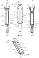
Figures 1-4 show a first exemplary embodiment of asyringe carrier 1 according to the present in invention.Figure 1 is a top view of thesyringe carrier 1 for supporting asyringe 2.Figure 2 is a lateral view of the syringe carrier offigure 1. Figure 3 is a longitudinal section of the syringe carrier offigure 1 in the section plane A-A.Figure 4 is a perspective view of the syringe carrier offigure 1 without thesyringe 2. - As shown in
Figures 1-4 , thesyringe carrier 1 comprises an elongate body 1.1 arranged to receive the barrel 2.1. In this exemplary embodiment, the body 1.1 has a cylindrical shape with an internal diameter corresponding to the diameter of the barrel 2.1. The body 1.1 comprises a collar 1.2 at a proximal end dimensioned to allow axial insertion of thesyringe 2 into thesyringe carrier 1 in a distal direction D. Resilient sections 1.1.1 extend distally from the collar 1.2. Distal ends of the sections 1.1.1 include shoulder sections 1.4 shaped as portions of a circle arranged in a transverse plane with respect to a longitudinal axis of thecarrier 1. The shoulder sections include facing surfaces 6. When the sections 1.1.1 are in a non-deflected position, the facingsurfaces 6 may abut each other, and the shoulder sections 1.4 form a circular shoulder (because the facingsurfaces 6 abut each other) adapted to engage the circumferential gap between the barrel 2.1 and theRNS 4. - The
syringe 2, withRNS 4 attached to theneedle 3, may be loaded into thesyringe carrier 1 by sliding thesyringe 2 in the distal direction D into thesyringe carrier 2. When theRNS 4 abuts the shoulder sections 1.4, additional axial force may be applied to cause the arms 1.3 to deflect radially. When theRNS 4 has bypassed the shoulder sections 1.4, the sections 1.1.1 may return to the non-deflected position, and the shoulder sections 1.4 may engage the circumferential gap between the barrel 2.1 and theRNS 4 and prevent thesyringe 2 from moving in the distal direction D relative to thesyringe carrier 1. - In an exemplary embodiment, the proximal end 1.5 of the body 1.1 may be arranged to receive a finger flange 2.3 of the
syringe 2. - In an exemplary embodiment, the shoulder sections 1.4 may include proximally-facing contoured surfaces to accommodate a proximal portion of the neck 2.2 of the
syringe 2 and distally-facing planar surfaces to abut theRNS 4. - In an exemplary embodiment,
viewing windows 5 may be arranged in the body 1.1 for allowing visual access to the barrel 2.1 of thesyringe 2 when thesyringe 2 is in thesyringe carrier 2. In an exemplary embodiment, thewindows 5 are formed when cut-outs in the arms 1.3 are substantially contiguous when the arms 1.3 are in the non-deflected position (as shown inFigure 1 ). A projection 1.6 may be formed around each cut-out, and when the sections 1.1.1 are in the non-deflected position, the projections 1.6 may form an outline for thewindow 5. In another exemplary embodiment, thewindows 5 may be formed in the sections 1.1.1. -
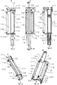
Figures 5-8 show a second exemplary embodiment of asyringe carrier 1 according to the present invention.Figure 6 is a lateral view of thesyringe carrier 1 offigure 5. Figure 7 is a longitudinal section of thesyringe carrier 1 offigure 5 in the section plane A-A.Figure 8 is a perspective view of the syringe carrier offigure 5 without thesyringe 2. - As shown in
Figures 5-8 , thesyringe carrier 1 comprises an elongate body 1.1 arranged to receive the barrel 2.1. In this exemplary embodiment, the body 1.1 is comprised of two resilient sections 1.1.1 which, when together, have a cylindrical shape with an internal diameter corresponding to the diameter of the barrel 2.1. Distal ends of the sections 1.1.1 of the body 1.1 comprise part of a collar 1.2 dimensioned to allow axial insertion of thesyringe 2 into thesyringe carrier 1. Resilient arms 1.3 are formed in the body 1.1. Distal ends of the arms 1.3 include shoulder sections 1.4 shaped as portions of a circle arranged in a transverse plane with respect to a longitudinal axis of thecarrier 1. The shoulder sections include facing surfaces 6. When the arms 1.3 are in a non-deflected position, the facingsurfaces 6 may abut the distal ends of the sections 1.1.1 of the body 1.1 to form a circular shoulder adapted to engage the circumferential gap between the barrel 2.1 and theRNS 4. - The
syringe 2, withRNS 4 attached to theneedle 3, may be loaded into thesyringe carrier 1 by sliding thesyringe 2 in the distal direction D into thesyringe carrier 2. When theRNS 4 abuts proximal ends of the sections 1.1.1, the sections 1.1.1 may deflect radially. When theRNS 4 has bypassed the proximal ends of the section 1.1.1, the sections 1.1.1 may return to the non-deflected position. When theRNS 4 abuts the shoulder sections 1.4, the arms 1.3 may deflect until theRNS 4 bypasses the shoulder sections 1.4. Then, the arms 1.3 may return to the non-deflected position, and the shoulder sections 1.4 and the collar 1.2 may engage the circumferential gap between the barrel 2.1 and theRNS 4 and prevent thesyringe 2 from moving in the distal direction D relative to thesyringe carrier 1. - In an exemplary embodiment, the proximal end 1.5 of the body 1.1 may be arranged to receive a finger flange 2.3 of the
syringe 2. The proximal end 1.5 may also include a retainer element 1.7 which is adapted to provide an abutment surface to prevent thesyringe 2 from disengaging thesyringe carrier 1 in the proximal direction D. - In an exemplary embodiment, the shoulder sections 1.4 may include proximally-facing contoured surfaces to accommodate a proximal portion of the neck 2.2 of the
syringe 2 and distally-facing planar surfaces to abut theRNS 4. - In an exemplary embodiment,
viewing windows 5 may be arranged in the body 1.1 for allowing visual access to the barrel 2.1 of thesyringe 2 when thesyringe 2 is in thesyringe carrier 2. In an exemplary embodiment, thewindows 5 are formed when cut-outs in the sections 1.1.1 are substantially contiguous when the sections 1.1.1 are in the non-deflected position (as shown inFigure 5 ). A projection 1.6 may be formed around each cut-out, and when the sections 1.1.1 are in the non-deflected position, the projections 1.6 may form an outline for thewindow 5. -
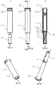
Figures 9-13 show a third exemplary embodiment of asyringe carrier 1 according to the present invention.Figure 9 is a top view of a third embodiment of asyringe carrier 1 for supporting asyringe 2.Figure 10 is a lateral view of thesyringe carrier 1 offigure 9. Figure 11 is a longitudinal section of thesyringe carrier 1 offigure 9 in the section plane A-A.Figure 12 is a perspective view of the syringe carrier offigure 9 without thesyringe 2.Figure 13 is another perspective view of the syringe carrier offigure 9 . - As shown in
Figures 9-13 , thesyringe carrier 1 comprises an elongate body 1.1 arranged to receive the barrel 2.1. In this exemplary embodiment, the body 1.1 is comprised of two sections 1.1.1 which, when together, have a cylindrical shape with an internal diameter corresponding to the diameter of the barrel 2.1. The sections 1.1.1 may be coupled by a side hinge which allows the section 1.1.1 to rotate relative to each other sufficient to receive thesyringe 2. Proximal and distal ends of the sections 1.1.1 include shoulder sections 1.4 shaped as portions of a circle arranged in a transverse plane with respect to a longitudinal axis of thecarrier 1. The shoulder sections include facing surfaces 6. When the sections 1.1.1 are in a closed position, the facingsurfaces 6 may abut each other so that the shoulder sections 1.4 form circular shoulders adapted to proximally abut a finger flange 2.3 on thesyringe 2 and to distally engage the circumferential gap between the barrel 2.1 and theRNS 4. The facing surfaces 6 of one section 1.1.1 may include holes 1.10 and the facingsurfaces 6 of the other section 1.1.1 may include pins 1.11 adapted to engage (e.g., frictionally, snap-fit, etc.) the holes 1.10 to secure the sections 1.1.1 in the closed position. - The
syringe 2, withRNS 4 attached to theneedle 3, may be loaded into thesyringe carrier 1 by opening the sections 1.1.1 about the hinge and placing thesyringe 2 in thesyringe carrier 2. When the sections 1.1.1 are closed, the pins 1.11 engage the holes 1.10, and the proximal shoulder sections 1.4 form circular shoulders adapted to proximally abut a finger flange 2.3 on thesyringe 2 and the distal shoulder section s1.4 to distally engage the circumferential gap between the barrel 2.1 and theRNS 4. Thus, thesyringe 2 is prevented from moving axially relative to thesyringe carrier 1. - In an exemplary embodiment, the proximal end 1.5 may include a retainer element 1.7 which is adapted to provide an abutment surface to prevent the
syringe 2 from disengaging thesyringe carrier 1 in the proximal direction D. - In an exemplary embodiment, the shoulder sections 1.4 may include proximally-facing contoured surfaces to accommodate a proximal portion of the neck 2.2 of the
syringe 2 and distally-facing planar surfaces to abut theRNS 4. - In an exemplary embodiment,
viewing windows 5 may be arranged in the body 1.1 for allowing visual access to the barrel 2.1 of thesyringe 2 when thesyringe 2 is in thesyringe carrier 2. In an exemplary embodiment, thewindows 5 are formed when cut-outs in the sections 1.1.1 are substantially contiguous when the sections 1.1.1 are in the closed position. A projection 1.6 may be formed around each cut-out, and when the sections 1.1.1 are in the non-deflected position, the projections 1.6 may form an outline for thewindow 5. -
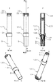
Figures 14-18 show a fourth exemplary embodiment of asyringe carrier 1 according to the present invention.Figure 14 is a top view of a fourth embodiment of asyringe carrier 1 for supporting asyringe 2.Figure 15 is a lateral view of thesyringe carrier 1 offigure 14. Figure 16 is a longitudinal section of thesyringe carrier 1 offigure 14 in the section plane A-A.Figure 17 is a perspective view of the syringe carrier offigure 14 without thesyringe 2.Figure 18 is another perspective view of the syringe carrier offigure 14 . - As shown in
Figures 14-18 , thesyringe carrier 1 comprises an elongate body 1.1 arranged to receive the barrel 2.1. In this exemplary embodiment, the body 1.1 has a cylindrical shape with an internal diameter corresponding to the diameter of the barrel 2.1. A distal end of the body 1.1 includes a shoulder sections 1.4 shaped as a portion of a circle arranged in a transverse plane with respect to a longitudinal axis of thecarrier 1, and at least one door 1.12 hingedly coupled to the body 1.1 and including a shoulder section 1.4. A hinge 1.9 coupling the door 1.12 to the body 1.1 may be provided on an axis parallel to the longitudinal axis of thesyringe carrier 1 or on an axis transverse to the longitudinal axis of thesyringe carrier 1. The shoulder section 1.4 includes facingsurfaces 6 whichabut facing surfaces 6 of the door 1.12 when the door 1.12 is in a closed position (as shown inFigure 14 ). When the door 1.12 is in the closed position, the facingsurfaces 6 may abut each other so that the shoulder sections 1.4 on the body 1.1 and the door 1.12 to form a circular shoulder adapted to engage the circumferential gap between the barrel 2.1 and theRNS 4. The facing surfaces 6 of the door 1.12 may include holes 1.10 and the facingsurfaces 6 of the body 1.1 may include pins 1.11 (or vice-versa) adapted to engage (e.g., frictionally, snap-fit, etc.) the holes 1.10 to secure the door 1.12 in the closed position. - The
syringe 2, withRNS 4 attached to theneedle 3, may be loaded into thesyringe carrier 1 by opening the door 1.12 and sliding thesyringe 2 into thesyringe carrier 1. When the circumferential gap between the barrel 2.1 and theRNS 4 engages the shoulder section 1.4 on the body 1.1, the door 1.12 may be closed to engage the gap and prevent thesyringe 2 from moving axially relative to thesyringe carrier 1. - In an exemplary embodiment, the shoulder sections 1.4 may include proximally-facing contoured surfaces to accommodate a proximal portion of the neck 2.2 of the
syringe 2 and distally-facing planar surfaces to abut theRNS 4. - In an exemplary embodiment, viewing windows (not shown) may be arranged in the body 1.1 for allowing visual access to the barrel 2.1 of the
syringe 2 when thesyringe 2 is in thesyringe carrier 2. In an exemplary embodiment, the windows are formed as cut-outs. -
Figures 19-23 show a fifth exemplary embodiment of asyringe carrier 1 according to the present invention.Figure 19 is a top view of a fifth embodiment of asyringe carrier 1 for supporting asyringe 2.Figure 20 is a lateral view of thesyringe carrier 1 offigure 19 . -
Figure 21 is a longitudinal section of thesyringe carrier 1 offigure 19 in the section plane A-A.Figure 22 is a perspective view of the syringe carrier offigure 19 without thesyringe 2.Figure 23 is another perspective view of the syringe carrier offigure 19 . - As shown in
Figures 19-23 , thesyringe carrier 1 comprises an elongate body 1.1 arranged to receive the barrel 2.1. In this exemplary embodiment, the body 1.1 is comprised of two sections 1.1.1 which, when together, have a cylindrical shape with an internal diameter corresponding to the diameter of the barrel 2.1. The sections 1.1.1 may be coupled together by clips. In an exemplary embodiment, a clip may comprise a eye 1.14 on a first section adapted to engage a hook 1.13 on a second section. The eye 1.14 may have a cross-section substantially equal to the cross-section of the hook 1.13 such that the eye 1.14 and hook 1.13 engage in a snap-fit. Distal ends of the sections 1.1.1 include shoulder sections 1.4 shaped as portions of a circle arranged in a transverse plane with respect to a longitudinal axis of thecarrier 1. The shoulder sections include facing surfaces 6. When the sections 1.1.1 are in a closed position, the facingsurfaces 6 may abut each other so that the shoulder sections 1.4 form circular shoulders adapted engage the circumferential gap between the barrel 2.1 and theRNS 4. Those of skill in the art will understand that the sections 1.1.1 may be hingedly connected. - The
syringe 2, withRNS 4 attached to theneedle 3, may be loaded into thesyringe carrier 1 by opening the sections 1.1.1 and placing thesyringe 2 in thesyringe carrier 2. When the sections 1.1.1 are closed, the eyes 1.14 engage the hooks 1.13 and the shoulder sections 1.4 engage the circumferential gap between the barrel 2.1 and theRNS 4. Thus, thesyringe 2 is prevented from moving axially relative to thesyringe carrier 1. - In an exemplary embodiment, the proximal end may include a retainer element which is adapted to provide an abutment surface to prevent the
syringe 2 from disengaging thesyringe carrier 1 in the proximal direction D. - In an exemplary embodiment, the shoulder sections 1.4 may include proximally-facing contoured surfaces to accommodate a proximal portion of the neck 2.2 of the
syringe 2 and distally-facing planar surfaces to abut theRNS 4. - In an exemplary embodiment, viewing windows may be arranged in the body 1.1 for allowing visual access to the barrel 2.1 of the
syringe 2 when thesyringe 2 is in thesyringe carrier 2. -
Figures 24-28 show a sixth exemplary embodiment of asyringe carrier 1 according to the present invention.Figure 24 is a top view of a sixth embodiment of asyringe carrier 1 for supporting asyringe 2.Figure 25 is a lateral view of thesyringe carrier 1 offigure 24. Figure 26 is a longitudinal section of thesyringe carrier 1 offigure 24 in the section plane A-A.Figure 27 is a perspective view of the syringe carrier offigure 24 without thesyringe 2.Figure 28 is another perspective view of the syringe carrier offigure 24 . - As shown in
Figures 24-28 , thesyringe carrier 1 comprises an elongate body 1.1 arranged to receive the barrel 2.1. In this exemplary embodiment, the body 1.1 has a partially cylindrical shape with an internal diameter corresponding to the diameter of the barrel 2.1. The body 1.1 may include a longitudinal slot (e.g., a cut-out) which is adapted to snap over the barrel 2.1 of thesyringe 2. Proximal and distal ends of the body 1.1 include clamps 1.15, 1.16 which are adapted to retain thesyringe 2 when in thesyringe carrier 1. The distal end of thebody 1 further includes shoulder sections 1.4 shaped as a portion of a circle arranged in a transverse plane with respect to a longitudinal axis of thecarrier 1. The shoulder sections 14 form circular shoulders adapted to engage the circumferential gap between the barrel 2.1 and theRNS 4. - The
syringe 2, withRNS 4 attached to theneedle 3, may be loaded into thesyringe carrier 1 by pressing the barrel 2.1 against the clamps 1.15, 1.16, causing the clamps 1.15, 1.16 to deflect and widen the longitudinal slot in the body 1.1. When the barrel 2.1 bypasses the clamps 1.15, 1.16, the clamps 1.15, 1.16 return to their non-deflected position and retain thesyringe 2 in thesyringe carrier 1. The shoulder sections 1.4 engage the circumferential gap between the barrel 2.1 and theRNS 4. Thus, thesyringe 2 is prevented from moving axially relative to thesyringe carrier 1. - In an exemplary embodiment, the proximal end may include a retainer element which is adapted to provide an abutment surface to prevent the
syringe 2 from disengaging thesyringe carrier 1 in the proximal direction D. - In an exemplary embodiment, the shoulder sections 1.4 may include proximally-facing contoured surfaces to accommodate a proximal portion of the neck 2.2 of the
syringe 2 and distally-facing planar surfaces to abut theRNS 4. - In an exemplary embodiment, a viewing window may be arranged in the body 1.1 for allowing visual access to the barrel 2.1 of the
syringe 2 when thesyringe 2 is in thesyringe carrier 2. -
Figures 29-33 show a seventh exemplary embodiment of asyringe carrier 1 according to the present invention.Figure 29 is a top view of a seventh embodiment of asyringe carrier 1 for supporting asyringe 2.Figure 30 is a lateral view of thesyringe carrier 1 offigure 29. Figure 31 is a longitudinal section of thesyringe carrier 1 offigure 29 in the section plane A-A.Figure 32 is a perspective view of the syringe carrier offigure 29 without thesyringe 2.Figure 33 is another perspective view of the syringe carrier offigure 29 . - As shown in
Figures 29-33 , thesyringe carrier 1 comprises an elongate body 1.1 arranged to receive the barrel 2.1. In this exemplary embodiment, the body 1.1 has a partially cylindrical shape with an internal diameter corresponding to the diameter of the barrel 2.1. The body 1.1 includes a collar 1.2 at its proximal end and may include a longitudinal slot (e.g., a cut-out) formed in the body 1.1 distally of the collar 1.2 which is adapted to snap over the barrel 2.1 of thesyringe 2. A pair of groove hinges 1.17 may be formed in the body 1.1 adjacent a proximal end of the slot. The distal end of thebody 1 includes shoulder sections 1.4 shaped as a portion of a circle arranged in a transverse plane with respect to a longitudinal axis of thecarrier 1. The shoulder sections 14 form circular shoulders adapted to engage the circumferential gap between the barrel 2.1 and theRNS 4. - The
syringe 2, withRNS 4 attached to theneedle 3, may be loaded into thesyringe carrier 1 by sliding thesyringe 2 through the collar 1.2 in the distal direction D. When theRNS 4 abuts the shoulder sections 1.4, the body 1.1 may radially deflect (e.g., rotate) about the groove hinges 1.17. When theRNS 4 bypasses the shoulder sections 1.4, the body 1.1 may return to its non-deflected position and retain thesyringe 2 in thesyringe carrier 1. The shoulder sections 1.4 engage the circumferential gap between the barrel 2.1 and theRNS 4. Thus, thesyringe 2 is prevented from moving axially relative to thesyringe carrier 1. - In an exemplary embodiment, the proximal end may include a retainer element which is adapted to provide an abutment surface to prevent the
syringe 2 from disengaging thesyringe carrier 1 in the proximal direction D. - In an exemplary embodiment, the shoulder sections 1.4 may include proximally-facing contoured surfaces to accommodate a proximal portion of the neck 2.2 of the
syringe 2 and distally-facing planar surfaces to abut theRNS 4. - In an exemplary embodiment, a viewing window may be arranged in the body 1.1 for allowing visual access to the barrel 2.1 of the
syringe 2 when thesyringe 2 is in thesyringe carrier 2. -
Figures 34-38 show an eighth exemplary embodiment of asyringe carrier 1 according to the present invention.Figure 34 is a top view of an eighth embodiment of asyringe carrier 1 for supporting asyringe 2.Figure 35 is a lateral view of thesyringe carrier 1 offigure 34. Figure 36 is a longitudinal section of thesyringe carrier 1 offigure 34 in the section plane A-A.Figure 37 is a perspective view of the syringe carrier offigure 34 without thesyringe 2.Figure 38 is another perspective view of the syringe carrier offigure 34 . - As shown in
Figures 34-38 , thesyringe carrier 1 comprises an elongate body 1.1 arranged to receive the barrel 2.1. In this exemplary embodiment, the body 1.1 has a cylindrical shape with an annular groove 1.19 adjacent its distal end which is adapted to engage acirclip 8. Thecirclip 8 may engage the circumferential gap between the barrel 1.2 and theRNS 4. - The
syringe 2, withRNS 4 attached to theneedle 3 and thecirclip 8 attached to thesyringe 2, may be loaded into thesyringe carrier 1 by sliding thesyringe 2 into thesyringe carrier 1 in the distal direction D. In a non-deflected position, an outer diameter of thecirclip 8 may be substantially equal to a diameter of the body 1.1. Thus, when thesyringe 2 with thecirclip 8 is inserted into thesyringe carrier 1, thecirclip 8 may deflect radially until thecirclip 8 reaches the annular groove 1.19. Thecirclip 8 may then expand to the non-deflected position and retain thesyringe 2 in an axial position relative to thesyringe carrier 1. That is, thecirclip 8 may engage the annular groove 1.19 and the circumferential gap between the barrel 2.1 and theRNS 4. Thus, thesyringe 2 is prevented from moving axially relative to thesyringe carrier 1. - In an exemplary embodiment, the proximal end may include a retainer element which is adapted to provide an abutment surface to prevent the
syringe 2 from disengaging thesyringe carrier 1 in the proximal direction D. - In an exemplary embodiment, the shoulder sections 1.4 may include proximally-facing contoured surfaces to accommodate a proximal portion of the neck 2.2 of the
syringe 2 and distally-facing planar surfaces to abut theRNS 4. - In an exemplary embodiment, a viewing window may be arranged in the body 1.1 for allowing visual access to the barrel 2.1 of the
syringe 2 when thesyringe 2 is in thesyringe carrier 2. -
Figures 39-43 show a ninth exemplary embodiment of asyringe carrier 1 according to the present invention.Figure 39 is a top view of a ninth embodiment of asyringe carrier 1 for supporting asyringe 2.Figure 40 is a lateral view of thesyringe carrier 1 offigure 39. Figure 41 is a longitudinal section of thesyringe carrier 1 offigure 39 in the section plane A-A.Figure 42 is a perspective view of the syringe carrier offigure 39 without thesyringe 2.Figure 43 is another perspective view of the syringe carrier offigure 39 . - As shown in
Figures 39-43 , thesyringe carrier 1 comprises an elongate body 1.1 arranged to receive the barrel 2.1. In this exemplary embodiment, the body 1.1 has a cylindrical shape with an annular groove 1.19 having at least one aperture 1.20 adjacent its distal end which is adapted to engage acirclip 8. - The
syringe 2, withRNS 4 attached to theneedle 3, may be loaded into thesyringe carrier 1 by sliding thesyringe 2 into thesyringe carrier 1 in the distal direction D. When the circumferential gap between the barrel 2.1 and theRNS 4 is aligned with the annular groove 1.19, thecirclip 8 may be coupled to the body 1.1 and engage the apertures 1.20. By extending inwardly through the apertures, thecirclip 8 may be coupled to the outside of the body 1.1 but engage the circumferential gap between the barrel 2.1 and theRNS 4. The engagement between thecirclip 8 and the apertures 1.20 prevents thecirclip 8 from translating relative to the body 1.1, and the engagement between thecirclip 8 and the circumferential gap prevents thesyringe 2 from moving axially relative to thesyringe carrier 1. - In an exemplary embodiment, the proximal end may include a retainer element which is adapted to provide an abutment surface to prevent the
syringe 2 from disengaging thesyringe carrier 1 in the proximal direction D. - In an exemplary embodiment, the shoulder sections 1.4 may include proximally-facing contoured surfaces to accommodate a proximal portion of the neck 2.2 of the
syringe 2 and distally-facing planar surfaces to abut theRNS 4. - In an exemplary embodiment, a viewing window may be arranged in the body 1.1 for allowing visual access to the barrel 2.1 of the
syringe 2 when thesyringe 2 is in thesyringe carrier 2. -
Figures 44-48 show a tenth exemplary embodiment of asyringe carrier 1 and atool 9 for inserting asyringe 2 into thesyringe carrier 1 according to the present invention. - As shown in
Figures 39-43 , thesyringe carrier 1 comprises an elongate body 1.1 arranged to receive the barrel 2.1. In this exemplary embodiment, the body 1.1 has an enlarged portion 1.21 on its distal end. The body 1.1 has cylindrical shape with a first diameter and the enlarged portion 1.21 has a second diameter, larger than the first diameter. The enlarged portion 1.21 has one or more resilient barbs 1.22 extending toward a longitudinal axis of the body 1.1 and angled toward a proximal end of the body 1.1. - The
syringe 2, withRNS 4 attached to theneedle 3, may be loaded into thesyringe carrier 1 by inserting thetool 9 into the enlarged portion 1.21 of thesyringe carrier 1. Thetool 9 may be a cylinder having an open end adapted to receive theRNS 4. Thetool 9 may have a third diameter substantially equal to the second diameter. As thetool 9 is inserted into the enlarged portion 1.21, thetool 9 engages and deflects the resilient barbs 1.22. When the barbs 1.22 are deflected, theRNS 4 can pass the barbs 1.22 in the distal direction D and extend from a distal opening of the body 1.1. When a finger flange 2.3 of thesyringe 2 abuts a proximal end of the body 1.1, thetool 9 may be removed and the barbs 1.22 may engage the circumferential gap between the barrel 2.1 and theRNS 4 to prevent thesyringe 2 from moving axially relative to thesyringe carrier 1. - In an exemplary embodiment, the proximal end may include a retainer element which is adapted to provide an abutment surface to prevent the
syringe 2 from disengaging thesyringe carrier 1 in the proximal direction D. - In an exemplary embodiment, the barbs 1.22 may include proximally-facing contoured surfaces to accommodate a proximal portion of the neck 2.2 of the
syringe 2 and distally-facing planar surfaces to abut theRNS 4. - In an exemplary embodiment, a viewing window may be arranged in the body 1.1 for allowing visual access to the barrel 2.1 of the
syringe 2 when thesyringe 2 is in thesyringe carrier 2. - It is apparent to those skilled in the art that the number of deflectable arms 1.3, shoulder sections 1.4, clips 8 may be varied without departing from the spirit and scope of the invention. Likewise, all the illustrated embodiments may be implemented with or without
viewing windows 5, projections 1.6, restraining features retainer elements 1.7 and clips. Different kinds of clips may likewise be applied. - Those of skill in the art will understand that modifications (additions and/or removals) of various components of the apparatuses, methods and/or systems and embodiments described herein may be made without departing from the full scope and spirit of the present invention, which encompass such modifications and any and all equivalents thereof.
Claims (15)
- A syringe carrier (1) comprising:a body (1.1) adapted to receive a barrel (2.1) of a syringe (2), the body (1.1) including at least two sections (1.1.1) having distal ends with shoulder sections (1.4), the shoulder sections (1.4) adapted to engage a circumferential gap between the barrel (2.1) of the syringe (2) and a needle shield (4) covering a needle (3) of the syringe (2), wherein the sections (1.1.1) are coupled via at least one hinge (1.9) and are movable between an open position and a closed position.
- The syringe carrier (1) according to claim 1, wherein the hinge (1.9) is a side hinge.
- The syringe carrier (1) according to claim 1 or 2, wherein a first section includes a pin (1.10) adapted to engage a hole (1.11) on a second section to secure the sections (1.1.1) in the closed position.
- The syringe carrier (1) according to any one of the preceding claims, wherein the shoulder sections (1.4) include proximally-facing contoured surfaces to accommodate a proximal portion of a neck (2.2) of the syringe (2) and distally-facing planar surfaces to abut the needle shield (4).
- The syringe carrier (1) according to any one of the preceding claims, wherein the body (1.1) includes one or more viewing windows (5).
- The syringe carrier (1) according to claim 5, wherein the viewing windows (5) are formed when cut-outs in the sections (1.1.1) are substantially contiguous when the sections (1.1.1) are in the closed position.
- The syringe carrier (1) according to claim 6, wherein a projection (1.6) is formed around each cut-out, and when the sections (1.1.1) are in the non-deflected position, the projections (1.6) form an outline for the viewing window (5).
- The syringe carrier (1) according to any one of the preceding claims, wherein the body (1.1) includes a retainer element (1.7) adapted to provide an abutment surface to prevent the syringe (2) from disengaging the syringe carrier (1) in a proximal direction (P).
- The syringe carrier (1) according to any one of the preceding claims, wherein the two resilient sections (1.1.1), when together, have a cylindrical shape with an internal diameter corresponding to the diameter of the barrel (2.1).
- The syringe carrier (1) according to any one of the preceding claims, wherein the collar (1.2) is partly formed by distal ends of the sections (1.1.1) of the body (1.1), the collar (1.2) being dimensioned to allow axial insertion of the syringe (2) into the syringe carrier (1).
- The syringe carrier (1) according to any one of the preceding claims, wherein the shoulder sections (1.4) are shaped as portions of a circle arranged in a transverse plane with respect to a longitudinal axis of the syringe carrier (1).
- Medicament delivery device comprising a syringe carrier (1) according to any one of the preceding claims.
- Medicament delivery device according to claim 12, further comprising a syringe (2) having a barrel (2.1) and a needle shield (4) covering a needle (3) of the syringe (2), wherein a circumferential gap is provided between the barrel (2.1) of the syringe (2) and the needle shield (4), wherein the barrel (2.1) is received in the body (1.1), wherein the shoulder sections (1.4) engage the circumferential gap.
- Medicament delivery device according to claim 13, wherein the syringe (2) is pre-filled with a medicament.
- Method for assembling a syringe (2) having a barrel (2.1) and a needle shield (4) covering a needle (3) of the syringe (2) into a syringe carrier (1) according to any one of claims 3 to 14, the method comprising: opening the sections (1.1.1) about the hinge (1.9) and placing the syringe (2) in the syringe carrier (1), closing the sections (1.1.1) such that the pin (1.11) engages the hole (1.10) and proximal shoulder sections (1.4) form circular shoulders adapted to proximally abut a finger flange (2.3) on the syringe (2) and distal shoulder sections (1.4) distally engage the circumferential gap to prevent the syringe (2) from moving in the distal direction (D) relative to the syringe carrier (1).
Applications Claiming Priority (3)
| Application Number | Priority Date | Filing Date | Title |
|---|---|---|---|
| EP11192585.5A EP2601992A1 (en) | 2011-12-08 | 2011-12-08 | Syringe carrier |
| EP12794996.4A EP2788055B1 (en) | 2011-12-08 | 2012-12-05 | Syringe carrier |
| PCT/EP2012/074466 WO2013083613A1 (en) | 2011-12-08 | 2012-12-05 | Syringe carrier |
Related Parent Applications (2)
| Application Number | Title | Priority Date | Filing Date |
|---|---|---|---|
| EP12794996.4A Division-Into EP2788055B1 (en) | 2011-12-08 | 2012-12-05 | Syringe carrier |
| EP12794996.4A Division EP2788055B1 (en) | 2011-12-08 | 2012-12-05 | Syringe carrier |
Publications (2)
| Publication Number | Publication Date |
|---|---|
| EP3153197A1 true EP3153197A1 (en) | 2017-04-12 |
| EP3153197B1 EP3153197B1 (en) | 2022-08-03 |
Family
ID=47278865
Family Applications (6)
| Application Number | Title | Priority Date | Filing Date |
|---|---|---|---|
| EP11192585.5A Ceased EP2601992A1 (en) | 2011-12-08 | 2011-12-08 | Syringe carrier |
| EP16195290.8A Active EP3153196B1 (en) | 2011-12-08 | 2012-12-05 | Syringe carrier |
| EP16195292.4A Active EP3153197B1 (en) | 2011-12-08 | 2012-12-05 | Syringe carrier |
| EP12794996.4A Active EP2788055B1 (en) | 2011-12-08 | 2012-12-05 | Syringe carrier |
| EP22167274.4A Pending EP4043052A1 (en) | 2011-12-08 | 2012-12-05 | Syringe carrier |
| EP22167268.6A Pending EP4043051A1 (en) | 2011-12-08 | 2012-12-05 | Syringe carrier |
Family Applications Before (2)
| Application Number | Title | Priority Date | Filing Date |
|---|---|---|---|
| EP11192585.5A Ceased EP2601992A1 (en) | 2011-12-08 | 2011-12-08 | Syringe carrier |
| EP16195290.8A Active EP3153196B1 (en) | 2011-12-08 | 2012-12-05 | Syringe carrier |
Family Applications After (3)
| Application Number | Title | Priority Date | Filing Date |
|---|---|---|---|
| EP12794996.4A Active EP2788055B1 (en) | 2011-12-08 | 2012-12-05 | Syringe carrier |
| EP22167274.4A Pending EP4043052A1 (en) | 2011-12-08 | 2012-12-05 | Syringe carrier |
| EP22167268.6A Pending EP4043051A1 (en) | 2011-12-08 | 2012-12-05 | Syringe carrier |
Country Status (14)
| Country | Link |
|---|---|
| US (17) | US10434258B2 (en) |
| EP (6) | EP2601992A1 (en) |
| JP (1) | JP6096206B2 (en) |
| KR (1) | KR20140105525A (en) |
| AU (1) | AU2012347359B2 (en) |
| BR (1) | BR112014013780A8 (en) |
| DK (3) | DK3153196T3 (en) |
| ES (1) | ES2623256T3 (en) |
| HU (1) | HUE032673T2 (en) |
| IL (1) | IL232989A0 (en) |
| MX (1) | MX2014006847A (en) |
| PL (1) | PL2788055T3 (en) |
| RU (1) | RU2618900C2 (en) |
| WO (1) | WO2013083613A1 (en) |
Cited By (5)
| Publication number | Priority date | Publication date | Assignee | Title |
|---|---|---|---|---|
| EP3791908A1 (en) * | 2011-12-08 | 2021-03-17 | Sanofi-Aventis Deutschland GmbH | Syringe carrier |
| US11103649B2 (en) | 2015-06-03 | 2021-08-31 | Sanofi-Aventis Deutschland Gmbh | Autoinjector and method of assembling |
| US11400222B2 (en) | 2011-12-08 | 2022-08-02 | Sanofi-Aventis Deutschland Gmbh | Syringe carrier |
| US12036392B1 (en) | 2013-03-14 | 2024-07-16 | Sanofi-Aventis Deutschland Gmbh | Medicament container carrier and adapter |
| US12318597B2 (en) | 2015-06-03 | 2025-06-03 | Sanofi-Aventis Deutschland Gmbh | Syringe carrier for an autoinjector and method of assembling |
Families Citing this family (26)
| Publication number | Priority date | Publication date | Assignee | Title |
|---|---|---|---|---|
| US20070202186A1 (en) | 2006-02-22 | 2007-08-30 | Iscience Interventional Corporation | Apparatus and formulations for suprachoroidal drug delivery |
| US8197435B2 (en) | 2006-05-02 | 2012-06-12 | Emory University | Methods and devices for drug delivery to ocular tissue using microneedle |
| WO2012051575A2 (en) | 2010-10-15 | 2012-04-19 | Iscience Interventional Corporation | Device for ocular access |
| MX336571B (en) * | 2011-01-24 | 2016-01-25 | Elcam Medical Agricultural Cooperative Ass Ltd | Injector. |
| CN104093436B (en) * | 2011-12-15 | 2016-11-02 | Shl集团有限责任公司 | automatic injection device |
| AU2013342275B2 (en) | 2012-11-08 | 2017-11-09 | Clearside Biomedical, Inc. | Methods and devices for the treatment of ocular diseases in human subjects |
| SG10201702674PA (en) | 2013-05-03 | 2017-06-29 | Clearside Biomedical Inc | Apparatus and methods for ocular injection |
| WO2014197317A1 (en) | 2013-06-03 | 2014-12-11 | Clearside Biomedical, Inc. | Apparatus and methods for drug delivery using multiple reservoirs |
| WO2015196085A2 (en) | 2014-06-20 | 2015-12-23 | Clearside Biomedical, Inc. | Variable diameter cannula and methods for controlling insertion depth for medicament delivery |
| EP4585241A3 (en) | 2014-08-10 | 2025-10-08 | Antares Pharma, Inc. | A syringe shock absorber for use in an injection device |
| USD750223S1 (en) | 2014-10-14 | 2016-02-23 | Clearside Biomedical, Inc. | Medical injector for ocular injection |
| JP6745809B2 (en) | 2015-02-20 | 2020-08-26 | ノボ・ノルデイスク・エー/エス | Needle unit for drug delivery device |
| TW201707738A (en) | 2015-06-03 | 2017-03-01 | 賽諾菲阿凡提斯德意志有限公司 | Syringe holder and autoinjector (2) |
| US10390901B2 (en) | 2016-02-10 | 2019-08-27 | Clearside Biomedical, Inc. | Ocular injection kit, packaging, and methods of use |
| JP2019514581A (en) | 2016-05-02 | 2019-06-06 | クリアサイド バイオメディカル,インコーポレイテッド | Systems and methods for ocular drug delivery |
| US10973681B2 (en) | 2016-08-12 | 2021-04-13 | Clearside Biomedical, Inc. | Devices and methods for adjusting the insertion depth of a needle for medicament delivery |
| JP7254022B2 (en) * | 2017-02-06 | 2023-04-07 | サノフィ-アベンティス・ドイチュラント・ゲゼルシャフト・ミット・ベシュレンクテル・ハフツング | Assembly nest for pen injection device with locking feature |
| WO2018204515A1 (en) | 2017-05-02 | 2018-11-08 | Georgia Tech Research Corporation | Targeted drug delivery methods using a microneedle |
| JP7235743B2 (en) * | 2017-10-28 | 2023-03-08 | ノボ・ノルデイスク・エー/エス | A syringe holder for a medical syringe and a method of forming a medical syringe assembly |
| ES2998749T3 (en) | 2019-03-15 | 2025-02-21 | Lilly Co Eli | Automatic injection system |
| BR112022005850A2 (en) | 2019-09-30 | 2022-06-21 | Amgen Inc | drug delivery device |
| KR102683457B1 (en) | 2020-04-21 | 2024-07-10 | 에스에이치엘 메디컬 아게 | syringe holder |
| EP4291264B1 (en) * | 2021-02-15 | 2026-04-08 | SHL Medical AG | Syringe carriers |
| AU2022234298A1 (en) | 2021-03-10 | 2023-08-31 | Amgen Inc. | Drug delivery device, subassembly for drug delivery device, syringe holder, and method of assembly |
| AU2023247113A1 (en) * | 2022-03-30 | 2024-11-14 | Janssen Biotech, Inc. | Shell for small vial to fit into injector or cap remover |
| CN122094726A (en) * | 2023-10-23 | 2026-05-26 | 诺和诺德股份有限公司 | An injection device with support ribs for supporting the glass cartridge. |
Citations (4)
| Publication number | Priority date | Publication date | Assignee | Title |
|---|---|---|---|---|
| US5865805A (en) * | 1997-07-16 | 1999-02-02 | Liebel-Flarsheim Company | Power injector and side loadable syringe support therefor for plunger pushrod type syringes |
| WO2001008727A1 (en) * | 1999-07-30 | 2001-02-08 | Medrad, Inc. | Injector systems and syringe adapters for use therewith |
| US20060161114A1 (en) * | 2002-07-12 | 2006-07-20 | Frederic Perot | Syringe accessory |
| EP2727617A1 (en) * | 2012-11-06 | 2014-05-07 | Sanofi-Aventis Deutschland GmbH | Autoinjector |
Family Cites Families (158)
| Publication number | Priority date | Publication date | Assignee | Title |
|---|---|---|---|---|
| GB407109A (en) * | 1932-01-19 | 1934-03-15 | Erwin Rippstein | Improvements in or relating to syringes for subcutaneous injection |
| GB829724A (en) | 1957-10-17 | 1960-03-02 | Hoechst Ag | Holder for an injection syringe |
| US3076455A (en) | 1958-12-19 | 1963-02-05 | Robert K Mcconnaughey | Holder for hypodermic syringe cartridges |
| US3026873A (en) | 1959-03-06 | 1962-03-27 | Pfizer & Co C | Aspirating hypodermic syringe holder |
| US3144178A (en) * | 1962-03-12 | 1964-08-11 | Stanley J Sarnoff | Cartridge holder |
| GB1122592A (en) | 1965-05-19 | 1968-08-07 | Franz Wantoch | Improvements in or relating to hypodermic syringes |
| US3880163A (en) | 1973-10-26 | 1975-04-29 | Jack H Ritterskamp | Medicinal syringe actuating device |
| US4563175A (en) | 1983-12-19 | 1986-01-07 | Lafond Margaret | Multiple syringe pump |
| US4838857A (en) | 1985-05-29 | 1989-06-13 | Becton, Dickinson And Company | Medical infusion device |
| US4643724A (en) | 1985-12-16 | 1987-02-17 | Alcon Laboratories, Inc. | Syringe holder |
| US4655751A (en) * | 1986-02-14 | 1987-04-07 | Harbaugh John T | Liquid dispensing and receiving syringe |
| US4735311A (en) | 1986-04-09 | 1988-04-05 | The West Company | Needle shield assembly |
| US4973318A (en) | 1988-02-10 | 1990-11-27 | D.C.P. Af 1988 A/S | Disposable syringe |
| US4820277A (en) | 1988-02-16 | 1989-04-11 | Norelli Robert A | Safety cover for syringe needles |
| US4931040A (en) * | 1988-04-13 | 1990-06-05 | Habley Medical Technology | Safety syringe having a combination needle cannula and articulating hub for retracting said cannula into a medication carpule |
| US4871355A (en) * | 1988-05-17 | 1989-10-03 | Steven Kikkawa | Injury resistant needle and blood collection tube holder |
| US5169392A (en) * | 1988-06-28 | 1992-12-08 | Sherwood Medical Company | Combined syringe and needle shield and method of manufacture |
| US4997422A (en) | 1989-01-31 | 1991-03-05 | Chow Peter P | Hypodermic syringe with needle shield |
| US4946447A (en) | 1989-02-14 | 1990-08-07 | Hardcastle Samuel L | Protective cover for hypodermic needle |
| US5085641A (en) | 1989-07-17 | 1992-02-04 | Survival Technology, Inc. | Conveniently carried frequent use auto-injector with improved cap structure |
| US5282793A (en) | 1989-10-02 | 1994-02-01 | Larson Eldon E | Syringe holder and applicator |
| US4990142A (en) | 1989-10-23 | 1991-02-05 | Gte Products Corporation | Hypodermic syringe |
| US4964866A (en) | 1989-11-22 | 1990-10-23 | Becton, Dickinson And Company | Needle sheath assembly |
| DE69114390T2 (en) | 1990-07-19 | 1996-06-05 | Nardino Righi | Safety syringe for single use. |
| US5350367A (en) * | 1990-11-06 | 1994-09-27 | Sterling Winthrop Inc. | Snap together hypodermic syringe holder |
| US5078698A (en) * | 1991-02-19 | 1992-01-07 | Sterling Drug Inc. | Axial eject hypodermic syringe holder |
| EP0518416A1 (en) | 1991-06-13 | 1992-12-16 | Duphar International Research B.V | Injection device |
| EP0525525B1 (en) | 1991-07-24 | 1995-05-03 | Medico Development Investment Company | Injector |
| US5322511A (en) | 1992-04-21 | 1994-06-21 | Sterling Winthrop Inc. | Portable hand-held power injector |
| US5383858B1 (en) | 1992-08-17 | 1996-10-29 | Medrad Inc | Front-loading medical injector and syringe for use therewith |
| US5320609A (en) | 1992-12-07 | 1994-06-14 | Habley Medical Technology Corporation | Automatic pharmaceutical dispensing syringe |
| US5290255A (en) | 1993-02-02 | 1994-03-01 | Vallelunga Anthony J | Apparatus for shielding a syringe needle |
| US5451214A (en) * | 1993-03-22 | 1995-09-19 | Hajishoreh; Kaveh-Karimi | Syringe apparatus |
| US5599309A (en) | 1993-03-24 | 1997-02-04 | Owen Mumford Limited | Injection devices |
| US5344407A (en) * | 1993-05-04 | 1994-09-06 | Ryan Dana W | Safety holder for pre-filled disposable syringe cartridge |
| US5383863A (en) | 1993-11-15 | 1995-01-24 | Mardones; Nestor E. | Attachment for maximum safety of hypodermic syringes |
| US5356395A (en) | 1993-12-14 | 1994-10-18 | Chen Shih Shuan | Safety syringe shield |
| US5368578A (en) * | 1994-03-10 | 1994-11-29 | Sterling Winthrop Inc. | Hypodermic syringe holder |
| US5722951A (en) | 1994-07-14 | 1998-03-03 | Marano; Carlos Jose | Hypodermic non-reusable syringes without voluntary intervention of the user |
| US5439450A (en) * | 1994-07-18 | 1995-08-08 | Becton, Dickinson And Company | Method of delivering a blood sample to an evacuated receptacle |
| US5616136A (en) | 1995-01-09 | 1997-04-01 | Med-Safe Systems, Inc. | Quick release needle removal apparatus |
| GB9506087D0 (en) * | 1995-03-24 | 1995-05-10 | Owen Mumford Ltd | Improvements relating to medical injection devices |
| US5779675A (en) * | 1995-08-25 | 1998-07-14 | Medrad, Inc. | Front load pressure jacket system with syringe holder |
| US5520653A (en) | 1995-09-01 | 1996-05-28 | Medrad, Inc. | Syringe adapter for front-loading medical injector |
| RU2172638C2 (en) | 1996-05-09 | 2001-08-27 | Юнивек Инк. | Disposable syringe with aspiration mechanism |
| US5709662A (en) | 1996-08-23 | 1998-01-20 | Becton Dickinson France, S.A. | Cartridge for an injection device |
| US6203530B1 (en) | 1997-01-28 | 2001-03-20 | Pos-T-Vac, Inc. | Auto-injection device |
| US6319234B1 (en) | 1997-02-12 | 2001-11-20 | Sergio Restelli | Disposable safety syringe |
| FR2764195B1 (en) | 1997-06-10 | 1999-10-15 | Blue Star Corp | SELF-RETRACTING NEEDLE SYRINGE |
| US5913844A (en) | 1997-06-17 | 1999-06-22 | Liebel-Flarsheim Company | Power injector and method providing removal of used disposable syringe |
| US6117108A (en) | 1997-08-20 | 2000-09-12 | Braun Melsungen Ag | Spring clip safety IV catheter |
| CA2300930C (en) | 1997-08-21 | 2007-10-16 | Owen Mumford Limited | Improvements relating to injection devices |
| WO1999022792A1 (en) | 1997-11-03 | 1999-05-14 | Ermanno Greco | Self-injection device |
| US6210369B1 (en) | 1997-12-16 | 2001-04-03 | Meridian Medical Technologies Inc. | Automatic injector |
| DE29801168U1 (en) | 1998-01-24 | 1999-09-23 | Medico Dev Investment Co | Injection device |
| US5925032A (en) | 1998-02-17 | 1999-07-20 | Alcon Laboratories, Inc. | Syringe cannula holder |
| US6090082A (en) | 1998-02-23 | 2000-07-18 | Becton, Dickinson And Company | Vial retainer interface to a medication delivery pen |
| US5928698A (en) | 1998-03-31 | 1999-07-27 | Soyad; Tony T. | Method of making a carambola beverage |
| DE19819409A1 (en) | 1998-04-30 | 1999-11-11 | Schering Ag | Injection device |
| SE9803662D0 (en) | 1998-10-26 | 1998-10-26 | Pharmacia & Upjohn Ab | autoinjector |
| US6059756A (en) | 1998-11-04 | 2000-05-09 | Yeh; Song-Hwa | Safety injection device |
| GB0003790D0 (en) | 2000-02-18 | 2000-04-05 | Astrazeneca Uk Ltd | Medical device |
| US6613022B1 (en) | 2000-05-05 | 2003-09-02 | Safety Syringes, Inc. | Passive needle guard for syringes |
| US6517517B1 (en) | 2000-06-08 | 2003-02-11 | Mayo Foundation For Medical Education And Research | Automated injection device for administration of liquid medicament |
| SE518981C2 (en) | 2000-12-14 | 2002-12-17 | Shl Medical Ab | autoinjector |
| US20020083564A1 (en) | 2001-01-03 | 2002-07-04 | James Blake T. | Flexible medication clip |
| US7144389B2 (en) | 2001-03-14 | 2006-12-05 | Tyco Healthcare Group, Lp | Safety shield for medical needles |
| DE20106697U1 (en) | 2001-04-18 | 2001-10-31 | B. Braun Melsungen Ag, 34212 Melsungen | Catheter introducer |
| GB0119520D0 (en) | 2001-08-10 | 2001-10-03 | Owen Mumford Ltd | Improvements relating to injection devices |
| FR2830765B1 (en) | 2001-10-15 | 2004-07-23 | Plastic Omnium Cie | SAFETY DEVICE FOR A SYRINGE |
| US20030105430A1 (en) | 2001-11-30 | 2003-06-05 | Elan Pharma International Limited Wil House | Automatic injector |
| WO2003059044A2 (en) | 2002-01-15 | 2003-07-24 | S.A.E. Afikim Computerized Dairy Management System | Identification of small ruminants |
| EP1334740A1 (en) | 2002-02-11 | 2003-08-13 | Sergio Restelli | Glass safety syringe and relative safety kit for glass syringe |
| GB0204673D0 (en) * | 2002-02-28 | 2002-04-10 | Dca Design Int Ltd | Improvements in and relating to a medicament delivery device |
| FR2837107B1 (en) | 2002-03-18 | 2005-02-25 | Sedat | NEEDLE PROTECTION DEVICE FOR SYRINGE, AND INJECTION DEVICE COMPRISING SYRINGE AND PROTECTIVE DEVICE |
| GB2396298A (en) | 2002-12-17 | 2004-06-23 | Pa Consulting Services | Injection device and drive coupling |
| GB2388033A (en) | 2002-05-02 | 2003-11-05 | Pa Consulting Services | Automatic injection device |
| US6979316B1 (en) | 2002-05-23 | 2005-12-27 | Seedlings Life Science Ventures Llc | Apparatus and method for rapid auto-injection of medication |
| WO2004020026A1 (en) | 2002-08-29 | 2004-03-11 | Novo Nordisk A/S | Frontloaded injection device |
| CH696186A5 (en) | 2002-11-25 | 2007-02-15 | Tecpharma Licensing Ag | Device for securing hypodermic needles. |
| GB2396816A (en) | 2002-12-17 | 2004-07-07 | Pa Consulting Services | Injection device |
| FR2852851B1 (en) | 2003-03-25 | 2006-01-06 | Sedat | NEEDLE PROTECTION DEVICE FOR SYRINGE, AND INJECTION DEVICE COMPRISING SYRINGE AND PROTECTIVE DEVICE |
| GB0312852D0 (en) | 2003-06-05 | 2003-07-09 | Owen Mumford Ltd | Improvements relating to syringe firing mechanisms |
| JP4400112B2 (en) | 2003-06-30 | 2010-01-20 | 生化学工業株式会社 | Syringe holder |
| JP4170165B2 (en) | 2003-06-30 | 2008-10-22 | Tdk株式会社 | Mask material for reactive ion etching, mask and dry etching method |
| US7500963B2 (en) | 2003-07-22 | 2009-03-10 | Safety Syringes, Inc. | Systems and methods for automatic medical injection with safeguard |
| US20050027255A1 (en) | 2003-07-31 | 2005-02-03 | Sid Technologies, Llc | Automatic injector |
| US20050101919A1 (en) | 2003-11-07 | 2005-05-12 | Lennart Brunnberg | Device for an injector |
| US20070260348A1 (en) | 2003-12-05 | 2007-11-08 | Ben Gordils | Portable table carrier for construction plans |
| AU2005205966B2 (en) | 2004-01-23 | 2010-08-05 | Shl Medical Ag | Injection device |
| GB2410188B (en) | 2004-01-23 | 2006-01-25 | Medical House Plc | Injection device |
| GB0403947D0 (en) | 2004-02-23 | 2004-03-24 | Topvine Medical Microsystems L | Patient records system |
| US7288078B2 (en) | 2004-04-12 | 2007-10-30 | P. Rowan Smith, Jr. | Spring loaded automatic retractable needle syringe |
| GB2414401B (en) | 2004-05-28 | 2009-06-17 | Cilag Ag Int | Injection device |
| GB2414775B (en) | 2004-05-28 | 2008-05-21 | Cilag Ag Int | Releasable coupling and injection device |
| EP1830910A4 (en) | 2004-11-04 | 2009-09-09 | Global Medisafe Holdings Ltd | Exchange needle retractable safety syringe |
| EP3002019B1 (en) | 2004-11-24 | 2021-06-09 | SHL Medical AG | Injection device |
| ITBZ20050003A1 (en) | 2005-02-09 | 2006-08-10 | Walter Bellini | HOOD FOR SYRINGE NEEDLES, IN PARTICULAR MEDICAL. |
| BRPI0608010A2 (en) | 2005-03-14 | 2009-11-03 | Global Medisafe Holdings Ltd | self retracting safety syringe |
| GB2424838B (en) | 2005-04-06 | 2011-02-23 | Cilag Ag Int | Injection device (adaptable drive) |
| GB2425062B (en) | 2005-04-06 | 2010-07-21 | Cilag Ag Int | Injection device |
| DE102005060929A1 (en) | 2005-09-14 | 2007-03-15 | Tecpharma Licensing Ag | Product e.g. insulin, injecting device, has housing and operating knob with locking units that are formed such that movement of operating knob in one direction has smaller resistance in contrast to movement in other direction |
| DE102005052502A1 (en) | 2005-11-03 | 2007-05-16 | Tecpharma Licensing Ag | Auto-injector activation trigger element |
| EP1981571A4 (en) | 2005-11-15 | 2010-06-09 | Global Medisafe Holdings Ltd | Safety syringe with plunger locking means |
| US20070173770A1 (en) | 2006-01-23 | 2007-07-26 | The Medical House Plc | Injection device |
| GB0601309D0 (en) | 2006-01-23 | 2006-03-01 | Medical House The Plc | Injection device |
| JP5062768B2 (en) | 2006-03-10 | 2012-10-31 | ノボ・ノルデイスク・エー/エス | INJECTION DEVICE AND METHOD FOR REPLACING CARTRIDGE OF THE DEVICE |
| GB2437922B (en) | 2006-05-10 | 2010-12-08 | Owen Mumford Ltd | Injection device comprising a window and a shutter element |
| GB2438591B (en) | 2006-06-01 | 2011-07-13 | Cilag Gmbh Int | Injection device |
| GB2438590B (en) | 2006-06-01 | 2011-02-09 | Cilag Gmbh Int | Injection device |
| CN2925504Y (en) | 2006-06-22 | 2007-07-25 | 李凤婷 | Self-destructive disposable safety syringe |
| CN100522269C (en) | 2006-08-08 | 2009-08-05 | 林作钱 | Needle retraction type safety injector |
| GB0704351D0 (en) | 2007-03-07 | 2007-04-11 | Medical House Plc The | Improved autoinjector |
| GB2451665B (en) | 2007-08-08 | 2012-09-26 | Cilag Gmbh Int | Injection device |
| GB2452030A (en) | 2007-08-10 | 2009-02-25 | Owen Mumford Ltd | Injection devices |
| JP2009077943A (en) | 2007-09-26 | 2009-04-16 | Jms Co Ltd | Syringe holder and syringe device |
| FR2922112B1 (en) | 2007-10-11 | 2009-12-04 | Rexam Pharma La Verpilliere | SAFETY DEVICE FOR A LIQUID INJECTION SYRINGE AND SYRINGE ASSEMBLY COMPRISING SAID DEVICE |
| CN201213944Y (en) | 2008-05-03 | 2009-04-01 | 宣建民 | Painless intramuscular injection device |
| CN201213949Y (en) | 2008-05-22 | 2009-04-01 | 林作钱 | Novel safe self-locking type self-destruction injector |
| GB2461087B (en) | 2008-06-19 | 2012-09-26 | Cilag Gmbh Int | Injection device |
| BRPI0910000B8 (en) | 2008-06-20 | 2021-06-22 | West Pharmaceutical Services Inc | automatic injection mechanism with front support cross reference to related requests |
| GB2463034B (en) | 2008-08-28 | 2012-11-07 | Owen Mumford Ltd | Autoinjection devices |
| US8876785B2 (en) | 2008-12-12 | 2014-11-04 | Shl Group Ab | Delivery member attachment device |
| JP5548701B2 (en) | 2008-12-23 | 2014-07-16 | サノフィ−アベンティス・ドイチュラント・ゲゼルシャフト・ミット・ベシュレンクテル・ハフツング | Needle assembly and drug delivery system |
| US8034034B2 (en) * | 2009-01-12 | 2011-10-11 | Howmedica Osteonics Corp. | Syringe and method of use |
| GB0900930D0 (en) | 2009-01-20 | 2009-03-04 | Future Injection Technologies Ltd | Injection device |
| EP2401009B1 (en) | 2009-02-26 | 2012-11-28 | Tecpharma Licensing AG | Product container holder for an injection device and for receiving a product container |
| CN102448511A (en) | 2009-03-31 | 2012-05-09 | 赛诺菲-安万特德国有限公司 | Fixtures |
| WO2010136076A1 (en) | 2009-05-29 | 2010-12-02 | Tecpharma Licensing Ag | Injection device comprising a device for separating a needle protection cap from a product container |
| PL2954914T3 (en) | 2009-05-29 | 2019-05-31 | Tecpharma Licensing Ag | Injection device, especially an automatic syringe equipped with a puncture protection and / or overload protection of the product container |
| EP2442856B1 (en) * | 2009-06-17 | 2024-02-07 | SHL Medical AG | Medicament container holder arrangement |
| GB2471473A (en) * | 2009-06-30 | 2011-01-05 | Owen Mumford Ltd | Syringe sheath remover |
| DE202009009119U1 (en) | 2009-07-02 | 2009-12-31 | B. Braun Melsungen Ag | Protection device for a hypodermic needle |
| US9233213B2 (en) | 2009-10-16 | 2016-01-12 | Janssen Biotech, Inc. | Palm activated drug delivery device |
| NZ705415A (en) | 2009-10-16 | 2016-01-29 | Janssen Biotech Inc | Palm activated drug delivery device |
| DK3427779T3 (en) | 2010-02-01 | 2021-02-15 | Sanofi Aventis Deutschland | CARTRIDGE HOLDER, MEDICINE ADMINISTRATION DEVICE AND PROCEDURE FOR HOLDING A CARTRIDGE IN A CARTRIDGE HOLDER |
| WO2011101378A1 (en) * | 2010-02-18 | 2011-08-25 | Sanofi-Aventis Deutschland Gmbh | Finger guard for an injection device |
| WO2011123024A1 (en) | 2010-03-31 | 2011-10-06 | Shl Group Ab | Medicament delivery device comprising feedback signalling means |
| EP2438952A1 (en) | 2010-10-08 | 2012-04-11 | Sanofi-Aventis Deutschland GmbH | Finger guard for an injection device |
| TWI459986B (en) | 2010-11-08 | 2014-11-11 | 瑞健集團股份有限公司 | Container holder assembly |
| US8992746B2 (en) | 2010-12-02 | 2015-03-31 | Dainippon Screen Mfg. Co., Ltd. | Anodizing apparatus |
| GB201020472D0 (en) | 2010-12-02 | 2011-01-19 | Oval Medical Technologies Ltd | A drive assembly for an autoinjector |
| WO2012089445A1 (en) | 2010-12-06 | 2012-07-05 | Novo Nordisk Health Care Ag | Wheel operated drug delivery device |
| WO2012164406A2 (en) | 2011-06-02 | 2012-12-06 | Ucb Pharma S.A. | Auto-injector |
| AU2012279539B2 (en) | 2011-07-05 | 2015-07-30 | Shl Medical Ag | Needle sheath remover assembly |
| PT3412323T (en) | 2011-09-09 | 2021-02-22 | Merck Patent Gmbh | A SELF-INJECTOR FOR EPINEPHRINE INJECTION |
| DE102011055389B4 (en) | 2011-11-15 | 2014-05-22 | Gerresheimer Regensburg Gmbh | Glass injection-side auxiliary assembly element, method for attaching a glass injection-side auxiliary assembly element and method for producing a glass injection-side auxiliary assembly element and arrangement of a glass syringe and a mounting auxiliary element |
| EP2601989A1 (en) | 2011-12-08 | 2013-06-12 | Sanofi-Aventis Deutschland GmbH | Syringe carrier |
| EP2601992A1 (en) | 2011-12-08 | 2013-06-12 | Sanofi-Aventis Deutschland GmbH | Syringe carrier |
| EP2601988A1 (en) | 2011-12-08 | 2013-06-12 | Sanofi-Aventis Deutschland GmbH | Syringe carrier |
| EP2601990A1 (en) | 2011-12-08 | 2013-06-12 | Sanofi-Aventis Deutschland GmbH | Syringe carrier |
| CN104093436B (en) | 2011-12-15 | 2016-11-02 | Shl集团有限责任公司 | automatic injection device |
| EP2606925A1 (en) | 2011-12-21 | 2013-06-26 | Sanofi-Aventis Deutschland GmbH | Autoinjector |
| EP2777684A1 (en) | 2013-03-14 | 2014-09-17 | Sanofi-Aventis Deutschland GmbH | Medicament container carrier and adapter |
| EP2781230B2 (en) | 2013-03-22 | 2025-05-14 | Ypsomed AG | Substance dispensing device with a signaling device |
| TW201705994A (en) | 2015-06-03 | 2017-02-16 | 賽諾菲阿凡提斯德意志有限公司 | Automatic syringe and assembly method |
| TW201700117A (en) | 2015-06-03 | 2017-01-01 | 賽諾菲阿凡提斯德意志有限公司 | Syringe bracket and assembly method for autoinjector |
| EP3999149A1 (en) | 2019-07-18 | 2022-05-25 | SHL Medical AG | Support structure, medicament delivery device and method of assemblying |
-
2011
- 2011-12-08 EP EP11192585.5A patent/EP2601992A1/en not_active Ceased
-
2012
- 2012-12-05 EP EP16195290.8A patent/EP3153196B1/en active Active
- 2012-12-05 EP EP16195292.4A patent/EP3153197B1/en active Active
- 2012-12-05 DK DK16195290.8T patent/DK3153196T3/en active
- 2012-12-05 EP EP12794996.4A patent/EP2788055B1/en active Active
- 2012-12-05 EP EP22167274.4A patent/EP4043052A1/en active Pending
- 2012-12-05 DK DK12794996.4T patent/DK2788055T3/en active
- 2012-12-05 BR BR112014013780A patent/BR112014013780A8/en not_active IP Right Cessation
- 2012-12-05 JP JP2014545232A patent/JP6096206B2/en active Active
- 2012-12-05 WO PCT/EP2012/074466 patent/WO2013083613A1/en not_active Ceased
- 2012-12-05 PL PL12794996T patent/PL2788055T3/en unknown
- 2012-12-05 RU RU2014127646A patent/RU2618900C2/en not_active IP Right Cessation
- 2012-12-05 HU HUE12794996A patent/HUE032673T2/en unknown
- 2012-12-05 ES ES12794996.4T patent/ES2623256T3/en active Active
- 2012-12-05 EP EP22167268.6A patent/EP4043051A1/en active Pending
- 2012-12-05 MX MX2014006847A patent/MX2014006847A/en unknown
- 2012-12-05 KR KR1020147018509A patent/KR20140105525A/en not_active Withdrawn
- 2012-12-05 AU AU2012347359A patent/AU2012347359B2/en not_active Ceased
- 2012-12-05 DK DK16195292.4T patent/DK3153197T3/en active
- 2012-12-05 US US14/362,537 patent/US10434258B2/en active Active
-
2014
- 2014-06-05 IL IL232989A patent/IL232989A0/en unknown
-
2018
- 2018-05-10 US US15/976,824 patent/US10646656B2/en active Active
-
2019
- 2019-03-14 US US16/353,268 patent/US10441719B2/en active Active
- 2019-03-14 US US16/353,282 patent/US11406763B2/en active Active
-
2020
- 2020-09-14 US US17/019,879 patent/US11980744B2/en active Active
- 2020-09-14 US US17/020,027 patent/US20200405961A1/en not_active Abandoned
-
2021
- 2021-07-21 US US17/381,737 patent/US11511043B2/en active Active
- 2021-11-02 US US17/453,271 patent/US11400222B2/en active Active
- 2021-11-02 US US17/453,263 patent/US11406764B2/en active Active
- 2021-11-02 US US17/453,257 patent/US11400221B2/en active Active
- 2021-11-02 US US17/453,278 patent/US11400223B2/en active Active
-
2024
- 2024-03-27 US US18/618,197 patent/US12102799B2/en active Active
- 2024-03-27 US US18/618,603 patent/US12102800B2/en active Active
- 2024-03-28 US US18/619,525 patent/US12102803B2/en active Active
- 2024-03-28 US US18/619,279 patent/US12102801B2/en active Active
- 2024-03-28 US US18/619,408 patent/US12102802B2/en active Active
- 2024-08-19 US US18/808,321 patent/US20250001083A1/en active Pending
Patent Citations (4)
| Publication number | Priority date | Publication date | Assignee | Title |
|---|---|---|---|---|
| US5865805A (en) * | 1997-07-16 | 1999-02-02 | Liebel-Flarsheim Company | Power injector and side loadable syringe support therefor for plunger pushrod type syringes |
| WO2001008727A1 (en) * | 1999-07-30 | 2001-02-08 | Medrad, Inc. | Injector systems and syringe adapters for use therewith |
| US20060161114A1 (en) * | 2002-07-12 | 2006-07-20 | Frederic Perot | Syringe accessory |
| EP2727617A1 (en) * | 2012-11-06 | 2014-05-07 | Sanofi-Aventis Deutschland GmbH | Autoinjector |
Cited By (21)
| Publication number | Priority date | Publication date | Assignee | Title |
|---|---|---|---|---|
| US12102800B2 (en) | 2011-12-08 | 2024-10-01 | Sanofi-Aventis Deutschland Gmbh | Syringe carrier |
| US12102799B2 (en) | 2011-12-08 | 2024-10-01 | Sanofi-Aventis Deutschland Gmbh | Syringe carrier |
| US11400222B2 (en) | 2011-12-08 | 2022-08-02 | Sanofi-Aventis Deutschland Gmbh | Syringe carrier |
| US11400223B2 (en) | 2011-12-08 | 2022-08-02 | Sanofi-Aventis Deutschland Gmbh | Syringe carrier |
| US11400221B2 (en) | 2011-12-08 | 2022-08-02 | Sanofi-Aventis Deutschland Gmbh | Syringe carrier |
| US11406764B2 (en) | 2011-12-08 | 2022-08-09 | Sanofi-Aventis Deutschland Gmbh | Syringe carrier |
| US11406763B2 (en) | 2011-12-08 | 2022-08-09 | Sanofi-Aventis Deutschland Gmbh | Syringe carrier |
| US11511043B2 (en) | 2011-12-08 | 2022-11-29 | Sanofi-Aventis Deutschland Gmbh | Syringe carrier |
| US11980744B2 (en) | 2011-12-08 | 2024-05-14 | Sanofi-Aventis Deutschland Gmbh | Syringe carrier |
| US12102802B2 (en) | 2011-12-08 | 2024-10-01 | Sanofi-Aventis Deutschland Gmbh | Syringe carrier |
| US12102803B2 (en) | 2011-12-08 | 2024-10-01 | Sanofi-Aventis Deutschland Gmbh | Syringe carrier |
| US12102801B2 (en) | 2011-12-08 | 2024-10-01 | Sanofi-Aventis Deutschland Gmbh | Syringe carrier |
| EP3791908A1 (en) * | 2011-12-08 | 2021-03-17 | Sanofi-Aventis Deutschland GmbH | Syringe carrier |
| US12036392B1 (en) | 2013-03-14 | 2024-07-16 | Sanofi-Aventis Deutschland Gmbh | Medicament container carrier and adapter |
| US12357757B2 (en) | 2013-03-14 | 2025-07-15 | Sanofi-Aventis Deutschland Gmbh | Medicament container carrier and adapter |
| US12370310B2 (en) | 2013-03-14 | 2025-07-29 | Sanofi-Aventis Deutschland Gmbh | Medicament container carrier and adapter |
| US12420015B2 (en) | 2013-03-14 | 2025-09-23 | Sanofi-Aventis Deutschland Gmbh | Medicament container carrier and adapter |
| US12427252B2 (en) | 2013-03-14 | 2025-09-30 | Sanofi-Aventis Deutschland Gmbh | Medicament container carrier and adapter |
| US12491317B2 (en) | 2013-03-14 | 2025-12-09 | Sanofi-Aventis Deutschland Gmbh | Medicament container carrier and adapter |
| US11103649B2 (en) | 2015-06-03 | 2021-08-31 | Sanofi-Aventis Deutschland Gmbh | Autoinjector and method of assembling |
| US12318597B2 (en) | 2015-06-03 | 2025-06-03 | Sanofi-Aventis Deutschland Gmbh | Syringe carrier for an autoinjector and method of assembling |
Also Published As
Similar Documents
| Publication | Publication Date | Title |
|---|---|---|
| US12102803B2 (en) | Syringe carrier | |
| AU2012347360B2 (en) | Syringe carrier | |
| AU2012347362B2 (en) | Syringe carrier | |
| AU2012347361B2 (en) | Syringe carrier | |
| HK40079863A (en) | Syringe carrier | |
| HK40079411A (en) | Syringe carrier | |
| HK40047516A (en) | Syringe carrier | |
| HK1197895B (en) | Syringe carrier | |
| HK1197895A (en) | Syringe carrier |
Legal Events
| Date | Code | Title | Description |
|---|---|---|---|
| PUAI | Public reference made under article 153(3) epc to a published international application that has entered the european phase |
Free format text: ORIGINAL CODE: 0009012 |
|
| STAA | Information on the status of an ep patent application or granted ep patent |
Free format text: STATUS: THE APPLICATION HAS BEEN PUBLISHED |
|
| AC | Divisional application: reference to earlier application |
Ref document number: 2788055 Country of ref document: EP Kind code of ref document: P |
|
| AK | Designated contracting states |
Kind code of ref document: A1 Designated state(s): AL AT BE BG CH CY CZ DE DK EE ES FI FR GB GR HR HU IE IS IT LI LT LU LV MC MK MT NL NO PL PT RO RS SE SI SK SM TR |
|
| STAA | Information on the status of an ep patent application or granted ep patent |
Free format text: STATUS: REQUEST FOR EXAMINATION WAS MADE |
|
| 17P | Request for examination filed |
Effective date: 20171012 |
|
| RBV | Designated contracting states (corrected) |
Designated state(s): AL AT BE BG CH CY CZ DE DK EE ES FI FR GB GR HR HU IE IS IT LI LT LU LV MC MK MT NL NO PL PT RO RS SE SI SK SM TR |
|
| STAA | Information on the status of an ep patent application or granted ep patent |
Free format text: STATUS: EXAMINATION IS IN PROGRESS |
|
| 17Q | First examination report despatched |
Effective date: 20190625 |
|
| GRAP | Despatch of communication of intention to grant a patent |
Free format text: ORIGINAL CODE: EPIDOSNIGR1 |
|
| STAA | Information on the status of an ep patent application or granted ep patent |
Free format text: STATUS: GRANT OF PATENT IS INTENDED |
|
| INTG | Intention to grant announced |
Effective date: 20210413 |
|
| GRAJ | Information related to disapproval of communication of intention to grant by the applicant or resumption of examination proceedings by the epo deleted |
Free format text: ORIGINAL CODE: EPIDOSDIGR1 |
|
| STAA | Information on the status of an ep patent application or granted ep patent |
Free format text: STATUS: EXAMINATION IS IN PROGRESS |
|
| INTC | Intention to grant announced (deleted) | ||
| GRAP | Despatch of communication of intention to grant a patent |
Free format text: ORIGINAL CODE: EPIDOSNIGR1 |
|
| STAA | Information on the status of an ep patent application or granted ep patent |
Free format text: STATUS: GRANT OF PATENT IS INTENDED |
|
| INTG | Intention to grant announced |
Effective date: 20210928 |
|
| GRAJ | Information related to disapproval of communication of intention to grant by the applicant or resumption of examination proceedings by the epo deleted |
Free format text: ORIGINAL CODE: EPIDOSDIGR1 |
|
| STAA | Information on the status of an ep patent application or granted ep patent |
Free format text: STATUS: EXAMINATION IS IN PROGRESS |
|
| GRAP | Despatch of communication of intention to grant a patent |
Free format text: ORIGINAL CODE: EPIDOSNIGR1 |
|
| STAA | Information on the status of an ep patent application or granted ep patent |
Free format text: STATUS: GRANT OF PATENT IS INTENDED |
|
| INTC | Intention to grant announced (deleted) | ||
| INTG | Intention to grant announced |
Effective date: 20220214 |
|
| GRAS | Grant fee paid |
Free format text: ORIGINAL CODE: EPIDOSNIGR3 |
|
| GRAA | (expected) grant |
Free format text: ORIGINAL CODE: 0009210 |
|
| STAA | Information on the status of an ep patent application or granted ep patent |
Free format text: STATUS: THE PATENT HAS BEEN GRANTED |
|
| AC | Divisional application: reference to earlier application |
Ref document number: 2788055 Country of ref document: EP Kind code of ref document: P |
|
| AK | Designated contracting states |
Kind code of ref document: B1 Designated state(s): AL AT BE BG CH CY CZ DE DK EE ES FI FR GB GR HR HU IE IS IT LI LT LU LV MC MK MT NL NO PL PT RO RS SE SI SK SM TR |
|
| REG | Reference to a national code |
Ref country code: AT Ref legal event code: REF Ref document number: 1508242 Country of ref document: AT Kind code of ref document: T Effective date: 20220815 Ref country code: CH Ref legal event code: EP |
|
| REG | Reference to a national code |
Ref country code: DE Ref legal event code: R096 Ref document number: 602012078572 Country of ref document: DE |
|
| REG | Reference to a national code |
Ref country code: IE Ref legal event code: FG4D |
|
| REG | Reference to a national code |
Ref country code: FR Ref legal event code: PLFP Year of fee payment: 11 |
|
| REG | Reference to a national code |
Ref country code: DK Ref legal event code: T3 Effective date: 20221028 |
|
| REG | Reference to a national code |
Ref country code: LT Ref legal event code: MG9D |
|
| REG | Reference to a national code |
Ref country code: NL Ref legal event code: MP Effective date: 20220803 |
|
| PG25 | Lapsed in a contracting state [announced via postgrant information from national office to epo] |
Ref country code: SE Free format text: LAPSE BECAUSE OF FAILURE TO SUBMIT A TRANSLATION OF THE DESCRIPTION OR TO PAY THE FEE WITHIN THE PRESCRIBED TIME-LIMIT Effective date: 20220803 Ref country code: RS Free format text: LAPSE BECAUSE OF FAILURE TO SUBMIT A TRANSLATION OF THE DESCRIPTION OR TO PAY THE FEE WITHIN THE PRESCRIBED TIME-LIMIT Effective date: 20220803 Ref country code: PT Free format text: LAPSE BECAUSE OF FAILURE TO SUBMIT A TRANSLATION OF THE DESCRIPTION OR TO PAY THE FEE WITHIN THE PRESCRIBED TIME-LIMIT Effective date: 20221205 Ref country code: NO Free format text: LAPSE BECAUSE OF FAILURE TO SUBMIT A TRANSLATION OF THE DESCRIPTION OR TO PAY THE FEE WITHIN THE PRESCRIBED TIME-LIMIT Effective date: 20221103 Ref country code: NL Free format text: LAPSE BECAUSE OF FAILURE TO SUBMIT A TRANSLATION OF THE DESCRIPTION OR TO PAY THE FEE WITHIN THE PRESCRIBED TIME-LIMIT Effective date: 20220803 Ref country code: LV Free format text: LAPSE BECAUSE OF FAILURE TO SUBMIT A TRANSLATION OF THE DESCRIPTION OR TO PAY THE FEE WITHIN THE PRESCRIBED TIME-LIMIT Effective date: 20220803 Ref country code: LT Free format text: LAPSE BECAUSE OF FAILURE TO SUBMIT A TRANSLATION OF THE DESCRIPTION OR TO PAY THE FEE WITHIN THE PRESCRIBED TIME-LIMIT Effective date: 20220803 Ref country code: FI Free format text: LAPSE BECAUSE OF FAILURE TO SUBMIT A TRANSLATION OF THE DESCRIPTION OR TO PAY THE FEE WITHIN THE PRESCRIBED TIME-LIMIT Effective date: 20220803 Ref country code: ES Free format text: LAPSE BECAUSE OF FAILURE TO SUBMIT A TRANSLATION OF THE DESCRIPTION OR TO PAY THE FEE WITHIN THE PRESCRIBED TIME-LIMIT Effective date: 20220803 |
|
| REG | Reference to a national code |
Ref country code: AT Ref legal event code: MK05 Ref document number: 1508242 Country of ref document: AT Kind code of ref document: T Effective date: 20220803 |
|
| PG25 | Lapsed in a contracting state [announced via postgrant information from national office to epo] |
Ref country code: PL Free format text: LAPSE BECAUSE OF FAILURE TO SUBMIT A TRANSLATION OF THE DESCRIPTION OR TO PAY THE FEE WITHIN THE PRESCRIBED TIME-LIMIT Effective date: 20220803 Ref country code: IS Free format text: LAPSE BECAUSE OF FAILURE TO SUBMIT A TRANSLATION OF THE DESCRIPTION OR TO PAY THE FEE WITHIN THE PRESCRIBED TIME-LIMIT Effective date: 20221203 Ref country code: HR Free format text: LAPSE BECAUSE OF FAILURE TO SUBMIT A TRANSLATION OF THE DESCRIPTION OR TO PAY THE FEE WITHIN THE PRESCRIBED TIME-LIMIT Effective date: 20220803 Ref country code: GR Free format text: LAPSE BECAUSE OF FAILURE TO SUBMIT A TRANSLATION OF THE DESCRIPTION OR TO PAY THE FEE WITHIN THE PRESCRIBED TIME-LIMIT Effective date: 20221104 |
|
| PG25 | Lapsed in a contracting state [announced via postgrant information from national office to epo] |
Ref country code: SM Free format text: LAPSE BECAUSE OF FAILURE TO SUBMIT A TRANSLATION OF THE DESCRIPTION OR TO PAY THE FEE WITHIN THE PRESCRIBED TIME-LIMIT Effective date: 20220803 Ref country code: RO Free format text: LAPSE BECAUSE OF FAILURE TO SUBMIT A TRANSLATION OF THE DESCRIPTION OR TO PAY THE FEE WITHIN THE PRESCRIBED TIME-LIMIT Effective date: 20220803 Ref country code: CZ Free format text: LAPSE BECAUSE OF FAILURE TO SUBMIT A TRANSLATION OF THE DESCRIPTION OR TO PAY THE FEE WITHIN THE PRESCRIBED TIME-LIMIT Effective date: 20220803 Ref country code: AT Free format text: LAPSE BECAUSE OF FAILURE TO SUBMIT A TRANSLATION OF THE DESCRIPTION OR TO PAY THE FEE WITHIN THE PRESCRIBED TIME-LIMIT Effective date: 20220803 |
|
| REG | Reference to a national code |
Ref country code: DE Ref legal event code: R097 Ref document number: 602012078572 Country of ref document: DE |
|
| PG25 | Lapsed in a contracting state [announced via postgrant information from national office to epo] |
Ref country code: SK Free format text: LAPSE BECAUSE OF FAILURE TO SUBMIT A TRANSLATION OF THE DESCRIPTION OR TO PAY THE FEE WITHIN THE PRESCRIBED TIME-LIMIT Effective date: 20220803 Ref country code: EE Free format text: LAPSE BECAUSE OF FAILURE TO SUBMIT A TRANSLATION OF THE DESCRIPTION OR TO PAY THE FEE WITHIN THE PRESCRIBED TIME-LIMIT Effective date: 20220803 |
|
| PLBE | No opposition filed within time limit |
Free format text: ORIGINAL CODE: 0009261 |
|
| STAA | Information on the status of an ep patent application or granted ep patent |
Free format text: STATUS: NO OPPOSITION FILED WITHIN TIME LIMIT |
|
| PG25 | Lapsed in a contracting state [announced via postgrant information from national office to epo] |
Ref country code: AL Free format text: LAPSE BECAUSE OF FAILURE TO SUBMIT A TRANSLATION OF THE DESCRIPTION OR TO PAY THE FEE WITHIN THE PRESCRIBED TIME-LIMIT Effective date: 20220803 |
|
| 26N | No opposition filed |
Effective date: 20230504 |
|
| REG | Reference to a national code |
Ref country code: BE Ref legal event code: MM Effective date: 20221231 |
|
| PG25 | Lapsed in a contracting state [announced via postgrant information from national office to epo] |
Ref country code: SI Free format text: LAPSE BECAUSE OF FAILURE TO SUBMIT A TRANSLATION OF THE DESCRIPTION OR TO PAY THE FEE WITHIN THE PRESCRIBED TIME-LIMIT Effective date: 20220803 Ref country code: LU Free format text: LAPSE BECAUSE OF NON-PAYMENT OF DUE FEES Effective date: 20221205 |
|
| PG25 | Lapsed in a contracting state [announced via postgrant information from national office to epo] |
Ref country code: IE Free format text: LAPSE BECAUSE OF NON-PAYMENT OF DUE FEES Effective date: 20221205 |
|
| PG25 | Lapsed in a contracting state [announced via postgrant information from national office to epo] |
Ref country code: BE Free format text: LAPSE BECAUSE OF NON-PAYMENT OF DUE FEES Effective date: 20221231 |
|
| PG25 | Lapsed in a contracting state [announced via postgrant information from national office to epo] |
Ref country code: HU Free format text: LAPSE BECAUSE OF FAILURE TO SUBMIT A TRANSLATION OF THE DESCRIPTION OR TO PAY THE FEE WITHIN THE PRESCRIBED TIME-LIMIT; INVALID AB INITIO Effective date: 20121205 |
|
| PG25 | Lapsed in a contracting state [announced via postgrant information from national office to epo] |
Ref country code: CY Free format text: LAPSE BECAUSE OF FAILURE TO SUBMIT A TRANSLATION OF THE DESCRIPTION OR TO PAY THE FEE WITHIN THE PRESCRIBED TIME-LIMIT Effective date: 20220803 |
|
| PG25 | Lapsed in a contracting state [announced via postgrant information from national office to epo] |
Ref country code: MK Free format text: LAPSE BECAUSE OF FAILURE TO SUBMIT A TRANSLATION OF THE DESCRIPTION OR TO PAY THE FEE WITHIN THE PRESCRIBED TIME-LIMIT Effective date: 20220803 Ref country code: IT Free format text: LAPSE BECAUSE OF FAILURE TO SUBMIT A TRANSLATION OF THE DESCRIPTION OR TO PAY THE FEE WITHIN THE PRESCRIBED TIME-LIMIT Effective date: 20220803 |
|
| PG25 | Lapsed in a contracting state [announced via postgrant information from national office to epo] |
Ref country code: MC Free format text: LAPSE BECAUSE OF FAILURE TO SUBMIT A TRANSLATION OF THE DESCRIPTION OR TO PAY THE FEE WITHIN THE PRESCRIBED TIME-LIMIT Effective date: 20220803 |
|
| PG25 | Lapsed in a contracting state [announced via postgrant information from national office to epo] |
Ref country code: MC Free format text: LAPSE BECAUSE OF FAILURE TO SUBMIT A TRANSLATION OF THE DESCRIPTION OR TO PAY THE FEE WITHIN THE PRESCRIBED TIME-LIMIT Effective date: 20220803 |
|
| PG25 | Lapsed in a contracting state [announced via postgrant information from national office to epo] |
Ref country code: BG Free format text: LAPSE BECAUSE OF FAILURE TO SUBMIT A TRANSLATION OF THE DESCRIPTION OR TO PAY THE FEE WITHIN THE PRESCRIBED TIME-LIMIT Effective date: 20220803 |
|
| PG25 | Lapsed in a contracting state [announced via postgrant information from national office to epo] |
Ref country code: MT Free format text: LAPSE BECAUSE OF FAILURE TO SUBMIT A TRANSLATION OF THE DESCRIPTION OR TO PAY THE FEE WITHIN THE PRESCRIBED TIME-LIMIT Effective date: 20220803 |
|
| PGFP | Annual fee paid to national office [announced via postgrant information from national office to epo] |
Ref country code: FR Payment date: 20250930 Year of fee payment: 14 |
|
| REG | Reference to a national code |
Ref country code: CH Ref legal event code: U11 Free format text: ST27 STATUS EVENT CODE: U-0-0-U10-U11 (AS PROVIDED BY THE NATIONAL OFFICE) Effective date: 20260101 |
|
| PGFP | Annual fee paid to national office [announced via postgrant information from national office to epo] |
Ref country code: DE Payment date: 20250930 Year of fee payment: 14 |
|
| PGFP | Annual fee paid to national office [announced via postgrant information from national office to epo] |
Ref country code: GB Payment date: 20251001 Year of fee payment: 14 |
|
| PGFP | Annual fee paid to national office [announced via postgrant information from national office to epo] |
Ref country code: DK Payment date: 20251212 Year of fee payment: 14 |
|
| PGFP | Annual fee paid to national office [announced via postgrant information from national office to epo] |
Ref country code: TR Payment date: 20251128 Year of fee payment: 14 |
|
| PGFP | Annual fee paid to national office [announced via postgrant information from national office to epo] |
Ref country code: CH Payment date: 20260101 Year of fee payment: 14 |