EP1334740A1 - Glass safety syringe and relative safety kit for glass syringe - Google Patents
Glass safety syringe and relative safety kit for glass syringe Download PDFInfo
- Publication number
- EP1334740A1 EP1334740A1 EP02425069A EP02425069A EP1334740A1 EP 1334740 A1 EP1334740 A1 EP 1334740A1 EP 02425069 A EP02425069 A EP 02425069A EP 02425069 A EP02425069 A EP 02425069A EP 1334740 A1 EP1334740 A1 EP 1334740A1
- Authority
- EP
- European Patent Office
- Prior art keywords
- sleeve
- sheath
- syringe
- tongues
- safety
- Prior art date
- Legal status (The legal status is an assumption and is not a legal conclusion. Google has not performed a legal analysis and makes no representation as to the accuracy of the status listed.)
- Withdrawn
Links
Images

Classifications
-
- A—HUMAN NECESSITIES
- A61—MEDICAL OR VETERINARY SCIENCE; HYGIENE
- A61M—DEVICES FOR INTRODUCING MEDIA INTO, OR ONTO, THE BODY; DEVICES FOR TRANSDUCING BODY MEDIA OR FOR TAKING MEDIA FROM THE BODY; DEVICES FOR PRODUCING OR ENDING SLEEP OR STUPOR
- A61M5/00—Devices for bringing media into the body in a subcutaneous, intra-vascular or intramuscular way; Accessories therefor, e.g. filling or cleaning devices, arm-rests
- A61M5/178—Syringes
- A61M5/31—Details
- A61M5/32—Needles; Details of needles pertaining to their connection with syringe or hub; Accessories for bringing the needle into, or holding the needle on, the body; Devices for protection of needles
- A61M5/3205—Apparatus for removing or disposing of used needles or syringes, e.g. containers; Means for protection against accidental injuries from used needles
- A61M5/321—Means for protection against accidental injuries by used needles
- A61M5/3243—Means for protection against accidental injuries by used needles being axially-extensible, e.g. protective sleeves coaxially slidable on the syringe barrel
- A61M5/326—Fully automatic sleeve extension, i.e. in which triggering of the sleeve does not require a deliberate action by the user
-
- A—HUMAN NECESSITIES
- A61—MEDICAL OR VETERINARY SCIENCE; HYGIENE
- A61M—DEVICES FOR INTRODUCING MEDIA INTO, OR ONTO, THE BODY; DEVICES FOR TRANSDUCING BODY MEDIA OR FOR TAKING MEDIA FROM THE BODY; DEVICES FOR PRODUCING OR ENDING SLEEP OR STUPOR
- A61M5/00—Devices for bringing media into the body in a subcutaneous, intra-vascular or intramuscular way; Accessories therefor, e.g. filling or cleaning devices, arm-rests
- A61M5/178—Syringes
- A61M5/31—Details
- A61M5/32—Needles; Details of needles pertaining to their connection with syringe or hub; Accessories for bringing the needle into, or holding the needle on, the body; Devices for protection of needles
- A61M5/3205—Apparatus for removing or disposing of used needles or syringes, e.g. containers; Means for protection against accidental injuries from used needles
- A61M5/321—Means for protection against accidental injuries by used needles
- A61M5/3243—Means for protection against accidental injuries by used needles being axially-extensible, e.g. protective sleeves coaxially slidable on the syringe barrel
- A61M5/3245—Constructional features thereof, e.g. to improve manipulation or functioning
- A61M2005/3247—Means to impede repositioning of protection sleeve from needle covering to needle uncovering position
-
- A—HUMAN NECESSITIES
- A61—MEDICAL OR VETERINARY SCIENCE; HYGIENE
- A61M—DEVICES FOR INTRODUCING MEDIA INTO, OR ONTO, THE BODY; DEVICES FOR TRANSDUCING BODY MEDIA OR FOR TAKING MEDIA FROM THE BODY; DEVICES FOR PRODUCING OR ENDING SLEEP OR STUPOR
- A61M5/00—Devices for bringing media into the body in a subcutaneous, intra-vascular or intramuscular way; Accessories therefor, e.g. filling or cleaning devices, arm-rests
- A61M5/178—Syringes
- A61M5/31—Details
- A61M5/32—Needles; Details of needles pertaining to their connection with syringe or hub; Accessories for bringing the needle into, or holding the needle on, the body; Devices for protection of needles
- A61M5/3205—Apparatus for removing or disposing of used needles or syringes, e.g. containers; Means for protection against accidental injuries from used needles
- A61M5/321—Means for protection against accidental injuries by used needles
- A61M5/3243—Means for protection against accidental injuries by used needles being axially-extensible, e.g. protective sleeves coaxially slidable on the syringe barrel
- A61M5/326—Fully automatic sleeve extension, i.e. in which triggering of the sleeve does not require a deliberate action by the user
- A61M2005/3261—Fully automatic sleeve extension, i.e. in which triggering of the sleeve does not require a deliberate action by the user triggered by radial deflection of the anchoring parts between sleeve and syringe barrel, e.g. spreading of sleeve retaining hooks having slanted surfaces by engagement with conically shaped collet of the piston rod during the last portion of the injection stroke of the plunger
-
- A—HUMAN NECESSITIES
- A61—MEDICAL OR VETERINARY SCIENCE; HYGIENE
- A61M—DEVICES FOR INTRODUCING MEDIA INTO, OR ONTO, THE BODY; DEVICES FOR TRANSDUCING BODY MEDIA OR FOR TAKING MEDIA FROM THE BODY; DEVICES FOR PRODUCING OR ENDING SLEEP OR STUPOR
- A61M5/00—Devices for bringing media into the body in a subcutaneous, intra-vascular or intramuscular way; Accessories therefor, e.g. filling or cleaning devices, arm-rests
- A61M5/178—Syringes
- A61M5/31—Details
- A61M5/32—Needles; Details of needles pertaining to their connection with syringe or hub; Accessories for bringing the needle into, or holding the needle on, the body; Devices for protection of needles
- A61M5/3205—Apparatus for removing or disposing of used needles or syringes, e.g. containers; Means for protection against accidental injuries from used needles
- A61M5/321—Means for protection against accidental injuries by used needles
- A61M5/3243—Means for protection against accidental injuries by used needles being axially-extensible, e.g. protective sleeves coaxially slidable on the syringe barrel
- A61M5/3271—Means for protection against accidental injuries by used needles being axially-extensible, e.g. protective sleeves coaxially slidable on the syringe barrel with guiding tracks for controlled sliding of needle protective sleeve from needle exposing to needle covering position
Definitions
- the present invention refers to a glass syringe, of the disposable type, provided with an automatic safety device to protect the needle once the injection has been performed.
- the present invention also refers to a relative safety kit that can be applied to a disposable glass syringe.
- a syringe generally comprises a cylindrical body open at the rear to receive a plunger.
- An internally hollow needle is mounted at the head of the syringe body.
- syringes generally present drawbacks from the point of view of safety. In fact, once the syringe has been used, the needle remains exposed at the head of the syringe body, with the risk of injuries or accidental needle sticks.
- plastic disposable syringes having safety devices to cover the needle are available on the market.
- Patent application PCT WO 99/37345 describes a disposable safety syringe which has a needle covering sleeve mounted axially on the syringe body and slidable from a retracted position in which it leaves the needle exposed to allow injection, to an extended position in which it completely covers the needle, preventing re-use of the syringe and acting as a protection against accidental needle sticks.
- the sleeve is automatically brought into the extracted safety position, by means of an automatic mechanism and without any intervention by the user.
- Glass syringes are generally designed to be able to be reused. In fact, the glass syringe body can be sterilized at high temperature. For this reason, glass syringes generally do not provide any safety device for protection of the needle once the injection has been performed.
- prefilled syringes in which the solution is already inside the barrel of the syringe, ready for injection, are widely available on the market.
- solutions such as vaccines, antidotes and the like which cannot be stored in plastic containers. Consequently, said solutions must necessarily be placed in prefilled glass syringes.
- An object of the present invention is to eliminate the prior art drawbacks, providing a glass safety syringe that is practical, versatile, economical and simple to make.
- Another object of the present invention is to provide such a glass safety syringe of the disposable type that is able to prevent further attempts at use.
- Another object of the present invention is to provide such a glass syringe that is extremely safe and able to prevent accidental injury and tampering after use.
- the syringe according to the invention comprises a glass syringe body hollow on the inside and open at the front and the rear, a plunger slidable inside the syringe body and provided at the rear with a manually operable stem and an injection needle mounted at the fore end of the syringe body.
- Locking means and stops are provided reciprocally in the sheath and sleeve such as to lock sleeve in position when it is in the retracted use position and in the advanced safety position.
- Operating means able to cooperate with the locking means when the plunger is at the end of the injection stroke are fitted to the rear part of the piston stem, to allow the sleeve to be moved from the retracted use position to the advanced safety position.
- the advantages of the syringe according to the invention are obvious in that it allows a glass syringe to be made into a safety syringe, by providing the possibility of covering the needle with the sleeve once the injection has been performed.
- the safety syringe according to the invention denoted as a whole by reference numeral 100, is described with the aid of the figures.
- the syringe 100 comprises a syringe body 1 (shown in Figures 2 and 4) made of glass.
- the syringe body 1 is substantially cylindrical in shape, is hollow on the inside and has a cylindrical chamber open at the front and rear.
- the body 1 has at its fore end a head 10 into which a needle 11 is sunk.
- the body 1 has at its rear end a flange 12 that protrudes radially therefrom to facilitate gripping by the user.
- a plunger 2 made of rubber can slide axially with a tight seal in the cylindrical chamber of the syringe body 1.
- the plunger 2 is supported at the fore end by a stem 20 made of glass or plastic.
- the stem 20 has at its rear end a flange 21 disposed on the outside of the syringe body 1 to be able to be operated manually by the user.
- a frusto conical block 22 disposed around the stem 20, near the flange 21 of the stem, is provided.
- the frusto conical block 22 has a tapered side surface with a diameter that increases toward the rear part of the stem 20.
- the frusto conical block 22 can be formed integrally in the rear part of the stem, or it can be a separate element to apply to the stem 20. In this latter case, the frusto conical block 22 has an axial hole 24 to be forcibly inserted, from the front part of the stem, until it abuts against the rear flange 21 of the stem. In this case, the frusto conical block 22 has an annular groove 23 to be able to yield elastically.
- a tubular sheath 3 that almost entirely covers the side surface of the syringe body 1 is mounted on the syringe body 1.
- the sheath 3 comprises at its fore end a collar 30 which protrudes radially outward so as to define an annular abutment surface 35.
- each longitudinal slot 32 defines a rear abutment surface 33 and a front abutment surface 34.
- the sheath 3 is made of plastic material and is elastically forced and fixed on the glass body 1.
- the syringe body 1, with the sheath 3 integral therewith, is mounted axially slidably inside a substantially cylindrical sleeve 4, hollow on the inside. In this manner, the head 10 of the syringe body 1 protrudes forwardly and axially from the sleeve 4 and a needle-covering cap 8 is fitted to the head 10.
- the sleeve 4 has a cylindrical rear part 40 with a greater diameter and a cylindrical front part 41 with a smaller diameter, so as to define on the inside an annular abutment surface 42.
- a helicoidal compression spring 6 which winds around the sheath 3 is interposed between the annular abutment surface 35 of the collar 30 of the sheath 3 and the annular abutment surface 42 of the sleeve 4.
- two rear tongues 43 are formed in the side wall of the part 40 of the sheath with the largest diameter.
- the rear tongues 43 are disposed longitudinally in diametrically opposite positions and are flexible.
- Each rear tongue 43 has a rectangular slot 44 within which the respective tooth 31 of the collar 30 of the sheath snap engages, so as to firmly retain the sheath 3 inside the sleeve 4.
- Each rear tongue 43 is defined by two longitudinal parallel notches 45 which reach the end of the part with the greatest diameter 40. In this manner, each rear tongue 43 can bend radially outward. Furthermore, each rear tongue 43 has a rear part which protrudes rearward beyond the rear end of the part with the largest diameter, 40. The rear end of each tongue 43 has a tapered surface 46 able to cooperate with the tapered surface of the frusto conical block 22 of the stem.
- a flange 55 protrudes radially to facilitate gripping by the user.
- the rear flange 55 of the sleeve is not present in the area in which there are the rear tongues 43 so as not to interfere therewith.
- the flange 55 of the sleeve has in its rear wall an annular abutment surface against which the rear flange 12 of the glass body 1 abuts.
- central tongues 47 are formed in the lateral part of the part with the smallest diameter 41 of the sleeve.
- the central tongues 47 are disposed longitudinally in diametrically opposite positions and are flexible.
- Each central tongue 47 is defined by a substantially U-shaped notch 48, so as to be able to bend radially outward.
- Each central tongue 47 has an inwardly protruding tooth 49 able to engage in the respective longitudinal slot 32 of the sheath 3. In this manner, when the syringe body 1 with the sheath 3 are inserted inside the sleeve 4, the central tongues 47 are widened and then elastically snap back when the teeth 49 engage in the respective slots 32 in the sheath.
- Two front tongues 50 are formed in the side wall of the sleeve part 41 with the smallest diameter.
- the front tongues 50 are longitudinally disposed in diametrically opposite positions.
- Each front tongue 50 is defined by a substantially U-shaped notch 51, so as to be able to bend radially outward. Under normal conditions, each front tongue 50 converges inwardly and has at its front end an abutment surface 52.
- the chamber of the body 1 is pre-filled with a solution to be injected.
- the needle 11 is protected in the safety position inside the sleeve 4.
- the syringe 100 when the syringe 100 is in the safety position, any axial movement of the sleeve 4 with respect to the sheath and syringe body assembly is prevented.
- the front end of the sheath 3 abuts against the rear end 52 of the front tongues 50 which are convergent and the rear abutment surfaces 34 of the slots 32 in the sheath are in abutment against the respective teeth 49 of the central tongues 47 of the sleeve.
- the present invention besides referring to the safety syringe 100 as described, also refers to a safety kit comprising the sheath 3, the spring 6, the sleeve 4 and the frusto conical block 22, considered as separate pieces which are applied to a glass syringe of the known type to make it a safety syringe.
Abstract
A safety syringe (100) comprises a glass syringe body (1), a plunger (2) slidable
inside the syringe body (1) and provided at the rear with a manually operable stem
(20), an injection needle (11) mounted at the front end (10) of the syringe body (1), a
sheath (3) mounted integrally on the syringe body (1), a sleeve (4) mounted slidably
on the shcath to pass from a retracted use position to an advanced safety position, in
which the needle (11) is protected by the sleeve (4), locking means mutually provided
in the sheath and in the sleeve to lock the sleeve (4) in position when it is in the
retracted use position and in the forward safety position, and operating means (22)
integrally mounted with the stem (20) of the piston to cooperate with locking means
(43) so as to allow movement of the sleeve (4) from the retracted use position to the
advanced safety position.
Description
- The present invention refers to a glass syringe, of the disposable type, provided with an automatic safety device to protect the needle once the injection has been performed. The present invention also refers to a relative safety kit that can be applied to a disposable glass syringe.
- A syringe generally comprises a cylindrical body open at the rear to receive a plunger. An internally hollow needle is mounted at the head of the syringe body.
- Because of health regulations and to avoid transmission of infectious diseases, syringes must generally be used only once and then discarded. For this reason, there is a growing demand for disposable syringes adapted to prevent further use.
- Moreover, syringes generally present drawbacks from the point of view of safety. In fact, once the syringe has been used, the needle remains exposed at the head of the syringe body, with the risk of injuries or accidental needle sticks.
- To overcome these drawbacks, plastic disposable syringes having safety devices to cover the needle are available on the market.
- Patent application PCT WO 99/37345 describes a disposable safety syringe which has a needle covering sleeve mounted axially on the syringe body and slidable from a retracted position in which it leaves the needle exposed to allow injection, to an extended position in which it completely covers the needle, preventing re-use of the syringe and acting as a protection against accidental needle sticks.
- Once the injection has been performed, the sleeve is automatically brought into the extracted safety position, by means of an automatic mechanism and without any intervention by the user.
- Glass syringes, on the other hand, are generally designed to be able to be reused. In fact, the glass syringe body can be sterilized at high temperature. For this reason, glass syringes generally do not provide any safety device for protection of the needle once the injection has been performed.
- As is known, prefilled syringes in which the solution is already inside the barrel of the syringe, ready for injection, are widely available on the market. However, there exist some solutions such as vaccines, antidotes and the like which cannot be stored in plastic containers. Consequently, said solutions must necessarily be placed in prefilled glass syringes.
- For this reason and for reasons of hygiene and practicality, glass syringes of the disposable type exist on the market. Disposable glass syringes have the drawback of not having a safety device for protection of the needle.
- An object of the present invention is to eliminate the prior art drawbacks, providing a glass safety syringe that is practical, versatile, economical and simple to make.
- Another object of the present invention is to provide such a glass safety syringe of the disposable type that is able to prevent further attempts at use.
- Another object of the present invention is to provide such a glass syringe that is extremely safe and able to prevent accidental injury and tampering after use.
- These objects are achieved in accordance with the invention with the characteristics listed in appended independent claim 1.
- Advantageous embodiments of the invention are apparent from the dependent claims.
- The syringe according to the invention comprises a glass syringe body hollow on the inside and open at the front and the rear, a plunger slidable inside the syringe body and provided at the rear with a manually operable stem and an injection needle mounted at the fore end of the syringe body.
- To make this syringe a safety syringe according to the invention, a sheath integrally mounted on the glass syringe body and a sleeve slidably mounted on the sheath to pass from a retracted use position in which the needle protrudes forward from the sleeve to be able to perform the injection to an advanced safety position in which the needle is protected by the sleeve.
- Locking means and stops are provided reciprocally in the sheath and sleeve such as to lock sleeve in position when it is in the retracted use position and in the advanced safety position. Operating means able to cooperate with the locking means when the plunger is at the end of the injection stroke are fitted to the rear part of the piston stem, to allow the sleeve to be moved from the retracted use position to the advanced safety position.
- The advantages of the syringe according to the invention are obvious in that it allows a glass syringe to be made into a safety syringe, by providing the possibility of covering the needle with the sleeve once the injection has been performed.
- Further characteristics of the invention will be made clearer by the detailed description that follows, referring to a purely exemplary and therefore unrestrictive embodiment thereof, illustrated in the appended drawings, in which:
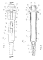
- Figure 1 is a top plan view of the safety syringe according to the invention, in the position ready for use, with a needle-covering cap mounted at the head of the syringe body;
- Figure 2 is an axial sectional view of the safety syringe of Figure 1, in which the syringe body and the piston stem are shown in side view;
- Figure 3 is an axial sectional view taken along the sectional plane III-III of Figure 1, in which the piston stem is shown in side view and in the end of injection position and the needle-covering cap has been removed;
- Figure 4 is an axial sectional view, like Figure 3, in which the needle is in the safety position;
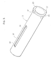
- Figure 5 is a perspective view, illustrating a sheath for covering a syringe body.
-
- The safety syringe according to the invention, denoted as a whole by
reference numeral 100, is described with the aid of the figures. - The
syringe 100 comprises a syringe body 1 (shown in Figures 2 and 4) made of glass. The syringe body 1 is substantially cylindrical in shape, is hollow on the inside and has a cylindrical chamber open at the front and rear. The body 1 has at its fore end ahead 10 into which aneedle 11 is sunk. The body 1 has at its rear end aflange 12 that protrudes radially therefrom to facilitate gripping by the user. - As shown in Figure 3, a
plunger 2 made of rubber can slide axially with a tight seal in the cylindrical chamber of the syringe body 1. Theplunger 2 is supported at the fore end by astem 20 made of glass or plastic. Thestem 20 has at its rear end aflange 21 disposed on the outside of the syringe body 1 to be able to be operated manually by the user. - In the rear part of the stem 20 a frusto
conical block 22, disposed around thestem 20, near theflange 21 of the stem, is provided. The frustoconical block 22 has a tapered side surface with a diameter that increases toward the rear part of thestem 20. - The frusto
conical block 22 can be formed integrally in the rear part of the stem, or it can be a separate element to apply to thestem 20. In this latter case, the frustoconical block 22 has anaxial hole 24 to be forcibly inserted, from the front part of the stem, until it abuts against therear flange 21 of the stem. In this case, the frustoconical block 22 has anannular groove 23 to be able to yield elastically. - A
tubular sheath 3 that almost entirely covers the side surface of the syringe body 1 is mounted on the syringe body 1. As shown also in Figure 5, thesheath 3 comprises at its fore end acollar 30 which protrudes radially outward so as to define anannular abutment surface 35. - Two
teeth 31 that protrude radially outward in diametrically opposite directions are provided on thecollar 30. Twolongitudinal slots 32 disposed in diametrically opposite positions are provided on the side surface of thesheath 3, level with theteeth 31. In this manner, eachlongitudinal slot 32 defines arear abutment surface 33 and afront abutment surface 34. - The
sheath 3 is made of plastic material and is elastically forced and fixed on the glass body 1. The syringe body 1, with thesheath 3 integral therewith, is mounted axially slidably inside a substantiallycylindrical sleeve 4, hollow on the inside. In this manner, thehead 10 of the syringe body 1 protrudes forwardly and axially from thesleeve 4 and a needle-covering cap 8 is fitted to thehead 10. - The
sleeve 4 has a cylindricalrear part 40 with a greater diameter and acylindrical front part 41 with a smaller diameter, so as to define on the inside anannular abutment surface 42. In this manner, as shown in Figure 2, ahelicoidal compression spring 6 which winds around thesheath 3 is interposed between theannular abutment surface 35 of thecollar 30 of thesheath 3 and theannular abutment surface 42 of thesleeve 4. - As better shown in Figure 1, two
rear tongues 43 are formed in the side wall of thepart 40 of the sheath with the largest diameter. Therear tongues 43 are disposed longitudinally in diametrically opposite positions and are flexible. Eachrear tongue 43 has arectangular slot 44 within which therespective tooth 31 of thecollar 30 of the sheath snap engages, so as to firmly retain thesheath 3 inside thesleeve 4. - Each
rear tongue 43 is defined by two longitudinalparallel notches 45 which reach the end of the part with thegreatest diameter 40. In this manner, eachrear tongue 43 can bend radially outward. Furthermore, eachrear tongue 43 has a rear part which protrudes rearward beyond the rear end of the part with the largest diameter, 40. The rear end of eachtongue 43 has atapered surface 46 able to cooperate with the tapered surface of the frustoconical block 22 of the stem. - At the rear end of the part with the
greater diameter 40, aflange 55 protrudes radially to facilitate gripping by the user. Therear flange 55 of the sleeve is not present in the area in which there are therear tongues 43 so as not to interfere therewith. Theflange 55 of the sleeve has in its rear wall an annular abutment surface against which therear flange 12 of the glass body 1 abuts. - In the lateral part of the part with the
smallest diameter 41 of the sleeve twocentral tongues 47 are formed. Thecentral tongues 47 are disposed longitudinally in diametrically opposite positions and are flexible. Eachcentral tongue 47 is defined by a substantiallyU-shaped notch 48, so as to be able to bend radially outward. - Each
central tongue 47 has an inwardly protrudingtooth 49 able to engage in the respectivelongitudinal slot 32 of thesheath 3. In this manner, when the syringe body 1 with thesheath 3 are inserted inside thesleeve 4, thecentral tongues 47 are widened and then elastically snap back when theteeth 49 engage in therespective slots 32 in the sheath. - Two
front tongues 50 are formed in the side wall of thesleeve part 41 with the smallest diameter. Thefront tongues 50 are longitudinally disposed in diametrically opposite positions. Eachfront tongue 50 is defined by a substantiallyU-shaped notch 51, so as to be able to bend radially outward. Under normal conditions, eachfront tongue 50 converges inwardly and has at its front end anabutment surface 52. - Operation of the
syringe 100 according to the invention will now be described. - With reference to Figures 1 and 2, in an initial condition the
spring 6 is compressed between theannular abutment surface 35 of thecollar 30 of thesheath 3 and theannular abutment surface 42 of thesleeve 4. Theteeth 32 of the sheath are engaged in theslots 44 of therear tongues 43 of the sleeve avoiding any axial movement of thesheath 2 and body 1 assembly with respect to thesleeve 4. Furthermore, theteeth 49 of thecentral tongues 47 are in abutment against thefront abutment surface 33 of thelongitudinal slot 32 of the sheath, avoiding any axial rearward movement of thesheath 3 with respect to thesleeve 4. - The chamber of the body 1 is pre-filled with a solution to be injected. Thus, when the injection is performed and the
plunger 2 reaches the end of its stroke in the chamber of the syringe body, as shown in Figure 3, the tapered surface of the frustoconical block 22 cooperates with the tapered surface of therear end 46 of therear tongues 43, causing outward radial bending thereof. - Consequently, the
teeth 31 of thesheath 3 disengage from theslots 44 of thetongues 43 and thesleeve 4 is no longer firmly constrained to thesheath 3 and syringe body 1 assembly. As a result, as shown in Figure 4, thespring 6 which was compressed is released, lengthening and causing axial forward sliding of thesleeve 4 with respect to the sheath and syringe body assembly, until theteeth 49 of thecentral tongues 47 of the sleeve abut against the respective rear abutment surfaces 34 of thelongitudinal slots 32 of the sheath. - Said axial movement of the
sleeve 4 with respect to the sheath and syringe body assembly is guided, since theteeth 49 of thecentral tongues 47 of the sleeve slide in the respectivelongitudinal slots 32 of the sheath. Furthermore, when therear end 52 of thefront tongues 50 of the sleeve passes the front end of thesheath 3, thefront tongues 50 converge elastically inward. - In this situation, the
needle 11 is protected in the safety position inside thesleeve 4. It should be noted that when thesyringe 100 is in the safety position, any axial movement of thesleeve 4 with respect to the sheath and syringe body assembly is prevented. In fact, the front end of thesheath 3 abuts against therear end 52 of thefront tongues 50 which are convergent and the rear abutment surfaces 34 of theslots 32 in the sheath are in abutment against therespective teeth 49 of thecentral tongues 47 of the sleeve. - It is evident that the present invention, besides referring to the
safety syringe 100 as described, also refers to a safety kit comprising thesheath 3, thespring 6, thesleeve 4 and the frustoconical block 22, considered as separate pieces which are applied to a glass syringe of the known type to make it a safety syringe. - Numerous variations and changes of detail within the reach of a person skilled in the art can be made to the present embodiment of the invention, without thereby departing from the scope of the invention as set forth in the appended claims.
Claims (10)
- A safety syringe (100) comprising:characterized in that it comprises:a glass syringe body (1) hollow on the inside and open at the front and rear,a plunger (2) slidable inside the syringe body (1), said plunger being provided at the rear with a manually operable stem (20) brought out of the syringe body by means of the rear end (21) thereof, andan injection needle (11) mounted at the front end (10) of the syringe body (1),a sheath (3) integrally mounted on said glass syringe body (1),a sleeve (4) slidably mounted on said sheath to pass from a retracted use position in which the needle (11) protrudes forward from said sleeve to be able to perform the injection to an advanced safety position in which the needle (11) is protected by said sleeve (4),locking and stop means, mutually provided in said sheath and in said sleeve to lock said sleeve (4) in position when it is in said retracted use position and said advanced safety position, andoperating means (22) integrally mounted to the rear part of the plunger stem (20) to cooperate with said locking means, when the plunger (2) is at the end of the injection stroke to allow movement of said sleeve (4) from the retracted use position to the advanced safety position.
- A safety syringe (100) according to claim 1, characterized in that it comprises spring means (6) interposed between said sleeve (4) and said sheath (3).
- A safety syringe (100) according to claim 2, characterized in that one end of said spring means is in abutment against an annular abutment surface (42) defined between a larger diameter part (40) and a smaller diameter part (41) of said sleeve and the other end of said spring means is in abutment against an annular abutment surface (35) defined by a collar (30) protruding outward at the fore end of said sheath (3).
- A safety syringe (100) according to any one of the preceding claims, characterized in that said locking means comprise two teeth (31) radially protruding from said sheath, in diametrically opposite directions, to engage in respective slots (44) provided in two rear elastic tongues (43) longitudinally formed in the rear part of the side wall of said sleeve (4).
- A safety syringe (100) according to claim 4, characterized in that each of said rear tongues (43) is defined by two longitudinal parallel notches formed in said side wall of the sleeve, up to the rear end of the sleeve, and the rear end of said tongues (43) protrudes radially beyond the rear end of the sleeve.
- A safety syringe (100) according to claim 4 or 5, characterized in that said operating means comprise a frusto conical block (22) cooperating with said rear tongues (43), when the plunger (2) reaches the end of the injection stroke, in order to make them diverge outward to disengage said teeth (31) of the sheath from said slots (44) of the rear tongues.
- A safety syringe (100) according to any one of the preceding claims, characterized in that said stop means comprise a pair of flexible central tongues (47), longitudinally provided in diametrically opposite positions in the central part of the side wall of said sleeve (4), said central tongues (4) being provided with respective teeth (49) protruding inward to engage in respective longitudinal grooves (32) provided in said sheath (3).
- A safety syringe according to claim 7, characterized in that each of said longitudinal grooves (32) in the sheath (3) has a rear abutment surface (33) which abuts against the respective tooth (49) of the central tongues of the sheath when said sheath (4) is in the retracted use position and a front abutment surface (34) that abuts against the respective tooth (49) when said sleeve (4) is in the advanced safety position.
- A safety syringe (100) according to any one of the preceding claims, characterized in that said stop means comprise a pair of flexible rear tongues (50), longitudinally provided in diametrically opposite positions in a rear part of the side wall of said sleeve, said central tongues (50) being inwardly convergent and having an abutment surface (52) able to abut against the front end of said sheath (3), when the sleeve (4) is in said advanced safety position.
- A safety syringe (100) according to claims 7 and 9, characterized in that each of said central tongues (47) and each of said front tongues (50) is defined by a respective substantially U-shaped notch (48, 51) formed respectively in the central part and in the front part of the side wall of said sleeve.
Priority Applications (12)
| Application Number | Priority Date | Filing Date | Title |
|---|---|---|---|
| EP02425069A EP1334740A1 (en) | 2002-02-11 | 2002-02-11 | Glass safety syringe and relative safety kit for glass syringe |
| AU2003210230A AU2003210230A1 (en) | 2002-02-11 | 2003-02-10 | Glass safety syringe and relative safety kit for glass syringe |
| DE60323815T DE60323815D1 (en) | 2002-02-11 | 2003-02-10 | SAFETY SYRINGE OF GLASS AND SAFETY KIT FOR GLASS TIP |
| US10/503,974 US20050096595A1 (en) | 2002-02-11 | 2003-02-10 | Glass safety syringe and relative safety kit for glass syringe |
| PCT/EP2003/001271 WO2003068297A1 (en) | 2002-02-11 | 2003-02-10 | Glass safety syringe and relative safety kit for glass syringe |
| RU2004127228/14A RU2311203C2 (en) | 2002-02-11 | 2003-02-10 | Safe glass syringe and corresponding safety set for glass syringe |
| CN03803652.5A CN1630541A (en) | 2002-02-11 | 2003-02-10 | Glass safety syringe and relative safety kit for glass syringe |
| EP03739461A EP1480699B1 (en) | 2002-02-11 | 2003-02-10 | Glass safety syringe and relative safety kit for glass syringe |
| JP2003567477A JP2005516740A (en) | 2002-02-11 | 2003-02-10 | Glass safety syringes and related safety kits for glass syringes |
| BR0303090-3A BR0303090A (en) | 2002-02-11 | 2003-02-10 | Glass safety syringe and corresponding safety glass syringe kit |
| ES03739461T ES2315508T3 (en) | 2002-02-11 | 2003-02-10 | GLASS SAFETY SYRINGE AND RELATED SAFETY KIT FOR GLASS SYRINGE. |
| AT03739461T ATE409504T1 (en) | 2002-02-11 | 2003-02-10 | GLASS SAFETY SYRINGE AND SAFETY KIT FOR GLASS SYRINGE |
Applications Claiming Priority (1)
| Application Number | Priority Date | Filing Date | Title |
|---|---|---|---|
| EP02425069A EP1334740A1 (en) | 2002-02-11 | 2002-02-11 | Glass safety syringe and relative safety kit for glass syringe |
Publications (1)
| Publication Number | Publication Date |
|---|---|
| EP1334740A1 true EP1334740A1 (en) | 2003-08-13 |
Family
ID=27589215
Family Applications (2)
| Application Number | Title | Priority Date | Filing Date |
|---|---|---|---|
| EP02425069A Withdrawn EP1334740A1 (en) | 2002-02-11 | 2002-02-11 | Glass safety syringe and relative safety kit for glass syringe |
| EP03739461A Expired - Lifetime EP1480699B1 (en) | 2002-02-11 | 2003-02-10 | Glass safety syringe and relative safety kit for glass syringe |
Family Applications After (1)
| Application Number | Title | Priority Date | Filing Date |
|---|---|---|---|
| EP03739461A Expired - Lifetime EP1480699B1 (en) | 2002-02-11 | 2003-02-10 | Glass safety syringe and relative safety kit for glass syringe |
Country Status (11)
| Country | Link |
|---|---|
| US (1) | US20050096595A1 (en) |
| EP (2) | EP1334740A1 (en) |
| JP (1) | JP2005516740A (en) |
| CN (1) | CN1630541A (en) |
| AT (1) | ATE409504T1 (en) |
| AU (1) | AU2003210230A1 (en) |
| BR (1) | BR0303090A (en) |
| DE (1) | DE60323815D1 (en) |
| ES (1) | ES2315508T3 (en) |
| RU (1) | RU2311203C2 (en) |
| WO (1) | WO2003068297A1 (en) |
Cited By (22)
| Publication number | Priority date | Publication date | Assignee | Title |
|---|---|---|---|---|
| WO2005089831A1 (en) * | 2004-03-16 | 2005-09-29 | Glenord Pty Ltd | Single use retractable syringe |
| WO2006008086A1 (en) * | 2004-07-21 | 2006-01-26 | Sergio Restelli | Safety kit for protecting the needle of a standard syringe, a glass syringe or a carpule |
| US7544180B2 (en) | 2003-02-27 | 2009-06-09 | B. Braun Melsungen Ag | Safety syringes |
| WO2010096511A1 (en) | 2009-02-17 | 2010-08-26 | Safety Syringes, Inc. | Improved plunger rod head for activating needle safety device |
| CN101052430B (en) * | 2004-07-16 | 2010-10-13 | 尤尼特拉克特注射器公司 | Syringe needle sheath |
| WO2012000837A1 (en) * | 2010-07-02 | 2012-01-05 | Sanofi-Aventis Deutschland Gmbh | Injection device with needle shield |
| WO2012000834A1 (en) * | 2010-07-02 | 2012-01-05 | Sanofi-Aventis Deutschland Gmbh | Safety device for a pre-filled syringe and injection device |
| US8162887B2 (en) | 2004-06-23 | 2012-04-24 | Abbott Biotechnology Ltd. | Automatic injection devices |
| US8636704B2 (en) | 2009-04-29 | 2014-01-28 | Abbvie Biotechnology Ltd | Automatic injection device |
| US8679061B2 (en) | 2006-06-30 | 2014-03-25 | Abbvie Biotechnology Ltd | Automatic injection device |
| US8708968B2 (en) | 2011-01-24 | 2014-04-29 | Abbvie Biotechnology Ltd. | Removal of needle shields from syringes and automatic injection devices |
| US8758301B2 (en) | 2009-12-15 | 2014-06-24 | Abbvie Biotechnology Ltd | Firing button for automatic injection device |
| US9180244B2 (en) | 2010-04-21 | 2015-11-10 | Abbvie Biotechnology Ltd | Wearable automatic injection device for controlled delivery of therapeutic agents |
| US9265887B2 (en) | 2011-01-24 | 2016-02-23 | Abbvie Biotechnology Ltd. | Automatic injection devices having overmolded gripping surfaces |
| WO2017125732A1 (en) * | 2016-01-19 | 2017-07-27 | Owen Mumford Ltd | Safety syringe |
| US9891296B2 (en) | 2013-09-13 | 2018-02-13 | MRI Interventions, Inc. | Intrabody fluid transfer devices, systems and methods |
| US10105485B2 (en) | 2010-04-16 | 2018-10-23 | MRI Interventions, Inc. | MRI surgical systems including MRI-compatible surgical cannulae for transferring a substance to and/or from a patient |
| US10576247B2 (en) | 2016-02-17 | 2020-03-03 | MRI Interventions, Inc. | Intrabody surgical fluid transfer assemblies with adjustable exposed cannula to needle tip length, related systems and methods |
| US10806867B2 (en) | 2011-01-24 | 2020-10-20 | E3D Agricultural Cooperative Association Ltd. | Injector |
| US11022664B2 (en) | 2018-05-09 | 2021-06-01 | Clearpoint Neuro, Inc. | MRI compatible intrabody fluid transfer systems and related devices and methods |
| US11253237B2 (en) | 2018-05-09 | 2022-02-22 | Clearpoint Neuro, Inc. | MRI compatible intrabody fluid transfer systems and related devices and methods |
| US11684750B2 (en) | 2019-10-08 | 2023-06-27 | Clearpoint Neuro, Inc. | Extension tube assembly and related medical fluid transfer systems and methods |
Families Citing this family (10)
| Publication number | Priority date | Publication date | Assignee | Title |
|---|---|---|---|---|
| US8062252B2 (en) | 2005-02-18 | 2011-11-22 | Becton, Dickinson And Company | Safety shield system for a syringe |
| MX2009009508A (en) | 2007-03-07 | 2009-09-16 | Becton Dickinson Co | Safety blood collection assembly with indicator. |
| US20080228147A1 (en) * | 2007-03-15 | 2008-09-18 | Bristol-Myers Squibb Company | Injector for use with pre-filled syringes and method of assembly |
| MX366271B (en) * | 2011-11-07 | 2019-07-04 | Safety Syringes Inc | Contact trigger release needle guard. |
| EP2601992A1 (en) | 2011-12-08 | 2013-06-12 | Sanofi-Aventis Deutschland GmbH | Syringe carrier |
| EP2601988A1 (en) * | 2011-12-08 | 2013-06-12 | Sanofi-Aventis Deutschland GmbH | Syringe carrier |
| GB201600988D0 (en) * | 2016-01-19 | 2016-03-02 | Owen Mumford Ltd | Auto-injector apparatus |
| WO2019024074A1 (en) * | 2017-08-03 | 2019-02-07 | 安徽迈菲思医疗器械有限公司 | Safety needle |
| US10675416B2 (en) * | 2018-08-17 | 2020-06-09 | David Harold Kovacs | Retractable syringe |
| CN113262349B (en) * | 2021-05-26 | 2022-04-15 | 东莞市一星医疗科技有限公司 | High-sensitivity high-pressure syringe |
Citations (5)
| Publication number | Priority date | Publication date | Assignee | Title |
|---|---|---|---|---|
| US5713873A (en) * | 1993-10-18 | 1998-02-03 | Marlene J. Mash | Hypodermic needle assembly |
| US6004296A (en) * | 1997-09-30 | 1999-12-21 | Becton Dickinson France, S.A. | Lockable safety shield assembly for a prefillable syringe |
| US6033387A (en) * | 1995-05-04 | 2000-03-07 | Sanofi-Synthelabo | Process for manufacturing an injection device of the prefilled type containing a dose of liquid for injection, and injection device produced |
| WO2001041841A2 (en) * | 1999-12-07 | 2001-06-14 | Plastef Investissements | Safety system for a syringe |
| US20020004649A1 (en) * | 1998-04-17 | 2002-01-10 | Hubert Jansen | Safety shield system for prefilled syringes |
-
2002
- 2002-02-11 EP EP02425069A patent/EP1334740A1/en not_active Withdrawn
-
2003
- 2003-02-10 DE DE60323815T patent/DE60323815D1/en not_active Expired - Fee Related
- 2003-02-10 JP JP2003567477A patent/JP2005516740A/en active Pending
- 2003-02-10 AT AT03739461T patent/ATE409504T1/en not_active IP Right Cessation
- 2003-02-10 AU AU2003210230A patent/AU2003210230A1/en not_active Abandoned
- 2003-02-10 CN CN03803652.5A patent/CN1630541A/en active Pending
- 2003-02-10 BR BR0303090-3A patent/BR0303090A/en not_active IP Right Cessation
- 2003-02-10 RU RU2004127228/14A patent/RU2311203C2/en not_active IP Right Cessation
- 2003-02-10 WO PCT/EP2003/001271 patent/WO2003068297A1/en active IP Right Grant
- 2003-02-10 EP EP03739461A patent/EP1480699B1/en not_active Expired - Lifetime
- 2003-02-10 ES ES03739461T patent/ES2315508T3/en not_active Expired - Lifetime
- 2003-02-10 US US10/503,974 patent/US20050096595A1/en not_active Abandoned
Patent Citations (5)
| Publication number | Priority date | Publication date | Assignee | Title |
|---|---|---|---|---|
| US5713873A (en) * | 1993-10-18 | 1998-02-03 | Marlene J. Mash | Hypodermic needle assembly |
| US6033387A (en) * | 1995-05-04 | 2000-03-07 | Sanofi-Synthelabo | Process for manufacturing an injection device of the prefilled type containing a dose of liquid for injection, and injection device produced |
| US6004296A (en) * | 1997-09-30 | 1999-12-21 | Becton Dickinson France, S.A. | Lockable safety shield assembly for a prefillable syringe |
| US20020004649A1 (en) * | 1998-04-17 | 2002-01-10 | Hubert Jansen | Safety shield system for prefilled syringes |
| WO2001041841A2 (en) * | 1999-12-07 | 2001-06-14 | Plastef Investissements | Safety system for a syringe |
Cited By (46)
| Publication number | Priority date | Publication date | Assignee | Title |
|---|---|---|---|---|
| US7544180B2 (en) | 2003-02-27 | 2009-06-09 | B. Braun Melsungen Ag | Safety syringes |
| WO2005089831A1 (en) * | 2004-03-16 | 2005-09-29 | Glenord Pty Ltd | Single use retractable syringe |
| US7850647B2 (en) | 2004-03-16 | 2010-12-14 | Glenord Pty. Ltd. | Single use retractable syringe |
| US8668670B2 (en) | 2004-06-23 | 2014-03-11 | Abbvie Biotechnology Ltd | Automatic injection devices |
| US8162887B2 (en) | 2004-06-23 | 2012-04-24 | Abbott Biotechnology Ltd. | Automatic injection devices |
| US9017287B2 (en) | 2004-06-23 | 2015-04-28 | Abbvie Biotechnology Ltd | Automatic injection devices |
| US9764090B2 (en) | 2004-06-23 | 2017-09-19 | Abbvie Biotechnology Ltd | Relating to automatic injection devices |
| CN101052430B (en) * | 2004-07-16 | 2010-10-13 | 尤尼特拉克特注射器公司 | Syringe needle sheath |
| US7935087B2 (en) | 2004-07-16 | 2011-05-03 | Unitract Syringe Pty. Ltd. | Syringe needle sheath |
| US8617122B2 (en) | 2004-07-16 | 2013-12-31 | Unitract Syringe Pty Ltd | Syringe needle sheath |
| WO2006008086A1 (en) * | 2004-07-21 | 2006-01-26 | Sergio Restelli | Safety kit for protecting the needle of a standard syringe, a glass syringe or a carpule |
| US8679061B2 (en) | 2006-06-30 | 2014-03-25 | Abbvie Biotechnology Ltd | Automatic injection device |
| US9486584B2 (en) | 2006-06-30 | 2016-11-08 | Abbvie Biotechnology Ltd. | Automatic injection device |
| WO2010096511A1 (en) | 2009-02-17 | 2010-08-26 | Safety Syringes, Inc. | Improved plunger rod head for activating needle safety device |
| US8636704B2 (en) | 2009-04-29 | 2014-01-28 | Abbvie Biotechnology Ltd | Automatic injection device |
| US9561328B2 (en) | 2009-04-29 | 2017-02-07 | Abbvie Biotechnology Ltd | Automatic injection device |
| US8758301B2 (en) | 2009-12-15 | 2014-06-24 | Abbvie Biotechnology Ltd | Firing button for automatic injection device |
| US10105485B2 (en) | 2010-04-16 | 2018-10-23 | MRI Interventions, Inc. | MRI surgical systems including MRI-compatible surgical cannulae for transferring a substance to and/or from a patient |
| US11793933B2 (en) | 2010-04-16 | 2023-10-24 | Clearpoint Neuro, Inc. | MRI-compatible surgical cannulae for transferring a substance to and/or from a patient |
| US9821117B2 (en) | 2010-04-21 | 2017-11-21 | Abbvie Biotechnology Ltd | Wearable automatic injection device for controlled delivery of therapeutic agents |
| US9180244B2 (en) | 2010-04-21 | 2015-11-10 | Abbvie Biotechnology Ltd | Wearable automatic injection device for controlled delivery of therapeutic agents |
| EP2588167B1 (en) | 2010-07-02 | 2018-02-21 | Sanofi-Aventis Deutschland GmbH | Safety device for a pre-filled syringe and injection device |
| EP3338840A1 (en) * | 2010-07-02 | 2018-06-27 | Sanofi-Aventis Deutschland GmbH | Safety device for a pre-filled syringe and injection device |
| WO2012000837A1 (en) * | 2010-07-02 | 2012-01-05 | Sanofi-Aventis Deutschland Gmbh | Injection device with needle shield |
| CN103068424B (en) * | 2010-07-02 | 2015-05-13 | 赛诺菲-安万特德国有限公司 | Safety device for a pre-filled syringe and injection device |
| AU2011273723B2 (en) * | 2010-07-02 | 2015-02-12 | Sanofi-Aventis Deutschland Gmbh | Safety device for a pre-filled syringe and injection device |
| US9586011B2 (en) | 2010-07-02 | 2017-03-07 | Sanofi-Aventis Deutschland Gmbh | Safety device for a pre-filled syringe and injection device |
| WO2012000834A1 (en) * | 2010-07-02 | 2012-01-05 | Sanofi-Aventis Deutschland Gmbh | Safety device for a pre-filled syringe and injection device |
| US8911401B2 (en) | 2010-07-02 | 2014-12-16 | Sanofi-Aventis Deutschland Gmbh | Safety device for a pre-filled syringe and injection device |
| US9789264B2 (en) | 2010-07-02 | 2017-10-17 | Sanofi-Aventis Deutschland Gmbh | Injection device with needle shield |
| CN103068424A (en) * | 2010-07-02 | 2013-04-24 | 赛诺菲-安万特德国有限公司 | Safety device for a pre-filled syringe and injection device |
| US8708968B2 (en) | 2011-01-24 | 2014-04-29 | Abbvie Biotechnology Ltd. | Removal of needle shields from syringes and automatic injection devices |
| US9265887B2 (en) | 2011-01-24 | 2016-02-23 | Abbvie Biotechnology Ltd. | Automatic injection devices having overmolded gripping surfaces |
| US10022503B2 (en) | 2011-01-24 | 2018-07-17 | Abbvie Biotechnology Ltd | Removal of needle shield from syringes and automatic injection devices |
| US9878102B2 (en) | 2011-01-24 | 2018-01-30 | Abbvie Biotechnology Ltd. | Automatic injection devices having overmolded gripping surfaces |
| US10806867B2 (en) | 2011-01-24 | 2020-10-20 | E3D Agricultural Cooperative Association Ltd. | Injector |
| US9339610B2 (en) | 2011-01-24 | 2016-05-17 | Abbvie Biotechnology Ltd | Removal of needle shield from syringes and automatic injection devices |
| US11565048B2 (en) | 2011-01-24 | 2023-01-31 | Abbvie Biotechnology Ltd. | Automatic injection devices having overmolded gripping surfaces |
| US9891296B2 (en) | 2013-09-13 | 2018-02-13 | MRI Interventions, Inc. | Intrabody fluid transfer devices, systems and methods |
| US11484665B2 (en) | 2016-01-19 | 2022-11-01 | Owen Mumford Limited | Safety syringe |
| WO2017125732A1 (en) * | 2016-01-19 | 2017-07-27 | Owen Mumford Ltd | Safety syringe |
| US10576247B2 (en) | 2016-02-17 | 2020-03-03 | MRI Interventions, Inc. | Intrabody surgical fluid transfer assemblies with adjustable exposed cannula to needle tip length, related systems and methods |
| US11541207B2 (en) | 2016-02-17 | 2023-01-03 | Clearpoint Neuro, Inc. | Intrabody surgical fluid transfer assemblies with adjustable exposed cannula to needle tip length, related systems and methods |
| US11253237B2 (en) | 2018-05-09 | 2022-02-22 | Clearpoint Neuro, Inc. | MRI compatible intrabody fluid transfer systems and related devices and methods |
| US11022664B2 (en) | 2018-05-09 | 2021-06-01 | Clearpoint Neuro, Inc. | MRI compatible intrabody fluid transfer systems and related devices and methods |
| US11684750B2 (en) | 2019-10-08 | 2023-06-27 | Clearpoint Neuro, Inc. | Extension tube assembly and related medical fluid transfer systems and methods |
Also Published As
| Publication number | Publication date |
|---|---|
| RU2004127228A (en) | 2005-04-10 |
| JP2005516740A (en) | 2005-06-09 |
| EP1480699A1 (en) | 2004-12-01 |
| US20050096595A1 (en) | 2005-05-05 |
| CN1630541A (en) | 2005-06-22 |
| EP1480699B1 (en) | 2008-10-01 |
| AU2003210230A1 (en) | 2003-09-04 |
| BR0303090A (en) | 2004-06-15 |
| RU2311203C2 (en) | 2007-11-27 |
| DE60323815D1 (en) | 2008-11-13 |
| ES2315508T3 (en) | 2009-04-01 |
| ATE409504T1 (en) | 2008-10-15 |
| WO2003068297A1 (en) | 2003-08-21 |
Similar Documents
| Publication | Publication Date | Title |
|---|---|---|
| EP1480699B1 (en) | Glass safety syringe and relative safety kit for glass syringe | |
| EP1562661B1 (en) | Guard mechanism attachable to standard syringe to transform it into a safety syringe | |
| US6673044B2 (en) | Automatic safety syringe | |
| US6712788B2 (en) | Automatic safety syringe | |
| US20030004468A1 (en) | Disposable safety syringe | |
| WO2006008086A1 (en) | Safety kit for protecting the needle of a standard syringe, a glass syringe or a carpule | |
| US5599309A (en) | Injection devices | |
| US6494863B1 (en) | One-use retracting syringe with positive needle retention | |
| US8192407B2 (en) | Syringe needle protective device and injecting device provided therewith | |
| AU2008285449B2 (en) | Injection device | |
| AU4826797A (en) | Retractable needle and syringe combination | |
| JPH0649074B2 (en) | Hypodermic syringe | |
| US6716191B2 (en) | Disposable syringe | |
| KR20220062395A (en) | Manual safety device, injection device comprising same, and method for manufacturing said injection device | |
| EP1362609A1 (en) | Disposable safety syringe with automatically guided outer sleeve | |
| EP1371382A1 (en) | Safety syringe having a protective sleeve | |
| WO2003009891A1 (en) | Single-use syringe | |
| WO2008110322A1 (en) | Safety mechanism for syringes, mounting method and safety syringe provided with the safety mechanism | |
| WO2004041332A1 (en) | Set of components for making a syringe into a disposable automatic safety syringe and relative disposable automatic safety syringe | |
| CN106668989B (en) | Retractable syringe | |
| RU2320374C2 (en) | Protection device attached to ordinary syringe to transform it to safe syringe | |
| EP2039385A1 (en) | Disposable syringe guarded in a preuse position (I) | |
| AU2002211994A1 (en) | Single-use syringe |
Legal Events
| Date | Code | Title | Description |
|---|---|---|---|
| PUAI | Public reference made under article 153(3) epc to a published international application that has entered the european phase |
Free format text: ORIGINAL CODE: 0009012 |
|
| AK | Designated contracting states |
Designated state(s): AT BE CH CY DE DK ES FI FR GB GR IE IT LI LU MC NL PT SE TR |
|
| AX | Request for extension of the european patent |
Extension state: AL LT LV MK RO SI |
|
| REG | Reference to a national code |
Ref country code: DE Ref legal event code: 8566 |
|
| STAA | Information on the status of an ep patent application or granted ep patent |
Free format text: STATUS: THE APPLICATION IS DEEMED TO BE WITHDRAWN |
|
| 18D | Application deemed to be withdrawn |
Effective date: 20040214 |