EP3153189B1 - Kammer für künstliche kreislaufunterstützung und membran - Google Patents
Kammer für künstliche kreislaufunterstützung und membran Download PDFInfo
- Publication number
- EP3153189B1 EP3153189B1 EP14892957.3A EP14892957A EP3153189B1 EP 3153189 B1 EP3153189 B1 EP 3153189B1 EP 14892957 A EP14892957 A EP 14892957A EP 3153189 B1 EP3153189 B1 EP 3153189B1
- Authority
- EP
- European Patent Office
- Prior art keywords
- chamber
- blood
- membrane
- compartment
- circulatory assistance
- Prior art date
- Legal status (The legal status is an assumption and is not a legal conclusion. Google has not performed a legal analysis and makes no representation as to the accuracy of the status listed.)
- Active
Links
Images


Classifications
-
- A—HUMAN NECESSITIES
- A61—MEDICAL OR VETERINARY SCIENCE; HYGIENE
- A61M—DEVICES FOR INTRODUCING MEDIA INTO, OR ONTO, THE BODY; DEVICES FOR TRANSDUCING BODY MEDIA OR FOR TAKING MEDIA FROM THE BODY; DEVICES FOR PRODUCING OR ENDING SLEEP OR STUPOR
- A61M60/00—Blood pumps; Devices for mechanical circulatory actuation; Balloon pumps for circulatory assistance
- A61M60/10—Location thereof with respect to the patient's body
- A61M60/104—Extracorporeal pumps, i.e. the blood being pumped outside the patient's body
- A61M60/109—Extracorporeal pumps, i.e. the blood being pumped outside the patient's body incorporated within extracorporeal blood circuits or systems
- A61M60/113—Extracorporeal pumps, i.e. the blood being pumped outside the patient's body incorporated within extracorporeal blood circuits or systems in other functional devices, e.g. dialysers or heart-lung machines
-
- A—HUMAN NECESSITIES
- A61—MEDICAL OR VETERINARY SCIENCE; HYGIENE
- A61M—DEVICES FOR INTRODUCING MEDIA INTO, OR ONTO, THE BODY; DEVICES FOR TRANSDUCING BODY MEDIA OR FOR TAKING MEDIA FROM THE BODY; DEVICES FOR PRODUCING OR ENDING SLEEP OR STUPOR
- A61M60/00—Blood pumps; Devices for mechanical circulatory actuation; Balloon pumps for circulatory assistance
- A61M60/80—Constructional details other than related to driving
- A61M60/855—Constructional details other than related to driving of implantable pumps or pumping devices
- A61M60/89—Valves
- A61M60/894—Passive valves, i.e. valves actuated by the blood
-
- A—HUMAN NECESSITIES
- A61—MEDICAL OR VETERINARY SCIENCE; HYGIENE
- A61M—DEVICES FOR INTRODUCING MEDIA INTO, OR ONTO, THE BODY; DEVICES FOR TRANSDUCING BODY MEDIA OR FOR TAKING MEDIA FROM THE BODY; DEVICES FOR PRODUCING OR ENDING SLEEP OR STUPOR
- A61M60/00—Blood pumps; Devices for mechanical circulatory actuation; Balloon pumps for circulatory assistance
- A61M60/10—Location thereof with respect to the patient's body
- A61M60/104—Extracorporeal pumps, i.e. the blood being pumped outside the patient's body
- A61M60/117—Extracorporeal pumps, i.e. the blood being pumped outside the patient's body for assisting the heart, e.g. transcutaneous or external ventricular assist devices
-
- A—HUMAN NECESSITIES
- A61—MEDICAL OR VETERINARY SCIENCE; HYGIENE
- A61M—DEVICES FOR INTRODUCING MEDIA INTO, OR ONTO, THE BODY; DEVICES FOR TRANSDUCING BODY MEDIA OR FOR TAKING MEDIA FROM THE BODY; DEVICES FOR PRODUCING OR ENDING SLEEP OR STUPOR
- A61M60/00—Blood pumps; Devices for mechanical circulatory actuation; Balloon pumps for circulatory assistance
- A61M60/10—Location thereof with respect to the patient's body
- A61M60/122—Implantable pumps or pumping devices, i.e. the blood being pumped inside the patient's body
- A61M60/126—Implantable pumps or pumping devices, i.e. the blood being pumped inside the patient's body implantable via, into, inside, in line, branching on, or around a blood vessel
- A61M60/148—Implantable pumps or pumping devices, i.e. the blood being pumped inside the patient's body implantable via, into, inside, in line, branching on, or around a blood vessel in line with a blood vessel using resection or like techniques, e.g. permanent endovascular heart assist devices
-
- A—HUMAN NECESSITIES
- A61—MEDICAL OR VETERINARY SCIENCE; HYGIENE
- A61M—DEVICES FOR INTRODUCING MEDIA INTO, OR ONTO, THE BODY; DEVICES FOR TRANSDUCING BODY MEDIA OR FOR TAKING MEDIA FROM THE BODY; DEVICES FOR PRODUCING OR ENDING SLEEP OR STUPOR
- A61M60/00—Blood pumps; Devices for mechanical circulatory actuation; Balloon pumps for circulatory assistance
- A61M60/10—Location thereof with respect to the patient's body
- A61M60/122—Implantable pumps or pumping devices, i.e. the blood being pumped inside the patient's body
- A61M60/165—Implantable pumps or pumping devices, i.e. the blood being pumped inside the patient's body implantable in, on, or around the heart
- A61M60/178—Implantable pumps or pumping devices, i.e. the blood being pumped inside the patient's body implantable in, on, or around the heart drawing blood from a ventricle and returning the blood to the arterial system via a cannula external to the ventricle, e.g. left or right ventricular assist devices
-
- A—HUMAN NECESSITIES
- A61—MEDICAL OR VETERINARY SCIENCE; HYGIENE
- A61M—DEVICES FOR INTRODUCING MEDIA INTO, OR ONTO, THE BODY; DEVICES FOR TRANSDUCING BODY MEDIA OR FOR TAKING MEDIA FROM THE BODY; DEVICES FOR PRODUCING OR ENDING SLEEP OR STUPOR
- A61M60/00—Blood pumps; Devices for mechanical circulatory actuation; Balloon pumps for circulatory assistance
- A61M60/20—Type thereof
- A61M60/247—Positive displacement blood pumps
- A61M60/253—Positive displacement blood pumps including a displacement member directly acting on the blood
- A61M60/268—Positive displacement blood pumps including a displacement member directly acting on the blood the displacement member being flexible, e.g. membranes, diaphragms or bladders
-
- A—HUMAN NECESSITIES
- A61—MEDICAL OR VETERINARY SCIENCE; HYGIENE
- A61M—DEVICES FOR INTRODUCING MEDIA INTO, OR ONTO, THE BODY; DEVICES FOR TRANSDUCING BODY MEDIA OR FOR TAKING MEDIA FROM THE BODY; DEVICES FOR PRODUCING OR ENDING SLEEP OR STUPOR
- A61M60/00—Blood pumps; Devices for mechanical circulatory actuation; Balloon pumps for circulatory assistance
- A61M60/40—Details relating to driving
- A61M60/424—Details relating to driving for positive displacement blood pumps
- A61M60/427—Details relating to driving for positive displacement blood pumps the force acting on the blood contacting member being hydraulic or pneumatic
- A61M60/43—Details relating to driving for positive displacement blood pumps the force acting on the blood contacting member being hydraulic or pneumatic using vacuum at the blood pump, e.g. to accelerate filling
-
- A—HUMAN NECESSITIES
- A61—MEDICAL OR VETERINARY SCIENCE; HYGIENE
- A61M—DEVICES FOR INTRODUCING MEDIA INTO, OR ONTO, THE BODY; DEVICES FOR TRANSDUCING BODY MEDIA OR FOR TAKING MEDIA FROM THE BODY; DEVICES FOR PRODUCING OR ENDING SLEEP OR STUPOR
- A61M60/00—Blood pumps; Devices for mechanical circulatory actuation; Balloon pumps for circulatory assistance
- A61M60/80—Constructional details other than related to driving
- A61M60/835—Constructional details other than related to driving of positive displacement blood pumps
- A61M60/837—Aspects of flexible displacement members, e.g. shapes or materials
-
- A—HUMAN NECESSITIES
- A61—MEDICAL OR VETERINARY SCIENCE; HYGIENE
- A61M—DEVICES FOR INTRODUCING MEDIA INTO, OR ONTO, THE BODY; DEVICES FOR TRANSDUCING BODY MEDIA OR FOR TAKING MEDIA FROM THE BODY; DEVICES FOR PRODUCING OR ENDING SLEEP OR STUPOR
- A61M60/00—Blood pumps; Devices for mechanical circulatory actuation; Balloon pumps for circulatory assistance
- A61M60/80—Constructional details other than related to driving
- A61M60/855—Constructional details other than related to driving of implantable pumps or pumping devices
- A61M60/869—Compliance chambers containing a gas or liquid other than blood to compensate volume variations of a blood chamber
-
- A—HUMAN NECESSITIES
- A61—MEDICAL OR VETERINARY SCIENCE; HYGIENE
- A61M—DEVICES FOR INTRODUCING MEDIA INTO, OR ONTO, THE BODY; DEVICES FOR TRANSDUCING BODY MEDIA OR FOR TAKING MEDIA FROM THE BODY; DEVICES FOR PRODUCING OR ENDING SLEEP OR STUPOR
- A61M60/00—Blood pumps; Devices for mechanical circulatory actuation; Balloon pumps for circulatory assistance
- A61M60/80—Constructional details other than related to driving
- A61M60/855—Constructional details other than related to driving of implantable pumps or pumping devices
- A61M60/89—Valves
- A61M60/894—Passive valves, i.e. valves actuated by the blood
- A61M60/896—Passive valves, i.e. valves actuated by the blood having flexible or resilient parts, e.g. flap valves
-
- F—MECHANICAL ENGINEERING; LIGHTING; HEATING; WEAPONS; BLASTING
- F04—POSITIVE - DISPLACEMENT MACHINES FOR LIQUIDS; PUMPS FOR LIQUIDS OR ELASTIC FLUIDS
- F04B—POSITIVE-DISPLACEMENT MACHINES FOR LIQUIDS; PUMPS
- F04B11/00—Equalisation of pulses, e.g. by use of air vessels; Counteracting cavitation
- F04B11/0008—Equalisation of pulses, e.g. by use of air vessels; Counteracting cavitation using accumulators
- F04B11/0016—Equalisation of pulses, e.g. by use of air vessels; Counteracting cavitation using accumulators with a fluid spring
-
- F—MECHANICAL ENGINEERING; LIGHTING; HEATING; WEAPONS; BLASTING
- F04—POSITIVE - DISPLACEMENT MACHINES FOR LIQUIDS; PUMPS FOR LIQUIDS OR ELASTIC FLUIDS
- F04B—POSITIVE-DISPLACEMENT MACHINES FOR LIQUIDS; PUMPS
- F04B43/00—Machines, pumps, or pumping installations having flexible working members
- F04B43/12—Machines, pumps, or pumping installations having flexible working members having peristaltic action
- F04B43/1253—Machines, pumps, or pumping installations having flexible working members having peristaltic action by using two or more rollers as squeezing elements, the rollers moving on an arc of a circle during squeezing
Definitions
- the present invention refers to a novel chamber for artificial circulatory assistance that, among several applications in which its importance and performance outstand, it has one related to cardiovascular procedures, notably to produce arterial capacitance, regulating blood pressure and producing aortic counterpulsation.
- the chamber according to the present invention can be applied in the most different situations, as a provisional or definitive implantable medical device for acting as a cardiovascular orthosis or prosthesis with functions of, among others, dampening the blood pressure peak and blood pumping, generating compliance in the arterial line of extracorporeal circulation circuit during cardiovascular surgical procedures requiring use of such technique, ventricular assistance device (VAD), aortic counterpulsation, optimizing aortic compliance on patients suffering from resistant hypertension and reduced arterial distensibility, pumping device for draining the cavity and pumping device for aspirating the cavity.
- VAD ventricular assistance device
- the present invention also refers to a membrane particularly developed to be used in fluid circulation chambers, such as the one mentioned above.
- the extracorporeal circulation is a technique used in cardiovascular procedures allowing temporarily replacement of cardiopulmonary functions.
- Heart pumping functions are performed by a mechanical pump and lung functions are replaced by an apparatus interconnected in series by a plastic manifold circuit, capable of performing gas exchanges with the blood.
- Figure 1 illustrates a basic extracorporeal circulation circuit having an oxygenator of the membranes, which comprises a cardiotomy reservoir (1), oxygen chamber (3), venous line (3), arterial line (4), arterial return line filter (5), arterial filter (6), arterial pump (7), suction pumps (8), ventricular decompression pump (9), cardioplegia delivery system (10), crystalloid cardioplegia (11), water inlet line (12), water outlet line (13) and gas line (14).
- This is the extracorporeal circulation circuit, wherein the structure and functioning are well known by the person skilled in the art.
- extracorporeal circulation is a procedure ruled by physiological principles, and under some circumstances could be required over periods of 1 hour, 2 hours and even weeks. In these cases, physiological deviations are more marked and, consequently, result in more complications to the organism.
- the great functional differences between human organism and artificial organs reflect on human body reaction during and right after the ECC. Hundreds surgeries are performed worldwide every day. The recovery without consequences is the most common result. However, some patients could present important complications produced by hypoxia, embolism, coagulopathy and blood dyscrasia, cerebral edema or edema in other organs, as well as alterations related to the exacerbated response from the organism protection and defense systems, which could produce complications in different levels of implications, possibly acting on preexisting morbidities and causing death.
- Figure 2 illustrates a blood pressure behavior diagram showing that the mechanical pumping produces a linear flow, i.e., without the occurrence of pulsation.
- the pre-bypass phase (A) the partial bypass period (B), total bypass (C), the period between (C) and (D), corresponding to the hypertension of the perfusion outset.
- blood pressure stabilizes before the beginning of the elevation by the action of catecholamine and other natural vasopressors and indicates the greater blood pressure elevation after 30 or 40 minutes from the perfusion, being observed and, afterwards, the perfusion output (F).
- the control mechanisms of the receptor sensitive to the pulse are absent on ECC with linear flow.
- the absence of arterial pulse triggers a series of events that result on the release of vasoactive substances in the blood flow, determining the closure of the arterioles and reducing the perfusion in capillary periphery resulting on the induction of a syndrome identified as Systemic Inflammatory Response Syndrome (SIRS) and poor perfusion of the tissues.
- SIRS Systemic Inflammatory Response Syndrome
- the ECC traditional technique consists basically of simulating the circulatory system connected to an oxygenator device able to promote gas exchanges in the blood, extracting carbon dioxide and providing oxygen, and a thermal exchanger coupled to the oxygenator device.
- This circuit is assembled in a heart-lung machine.
- the system is prepared and connected to a patient parallel to the normal circulatory system, by venoarterial access.
- the circuit is connected to the venous access through a cannula inserted in the right atrium or by two cannulas in the superior and inferior vena cava. Blood is drained through the venous line aperture to the venous reservoir, blood collecting device and, afterwards, reaches the blood pumping device, which produces the blood flow according to the patients' needs.
- blood reaches the oxygenator coupled to a heat exchanger system that enables controlling of the flow temperature when it passes through it.
- the temperature exchange occurs after the blood has reached the oxygenation chamber where it suffers gas exchanges.
- the oxygenation chamber contains an amount of hollow and microporous microfibers that are internally traveled by the air mixture flow enriched with oxygen and externally traveled by the blood flow.
- a continuous supply of air mixture enriched with oxygen is connected to the oxygenation chamber, providing oxygen to the blood while removes the excess of carbon dioxide. After the oxygenation, blood returns to the normal arterial circulation through an arterial access cannula.
- the blood pumping is executed by a peristaltic pump, a compressing pump segment is assembled on the roller pump pocket.
- the rollers are placed in a 180° angle in relation to the each other in a semicircular pocket with a 210° angle and they are adjusted to compress the manifold segment in its path over it, thus when it is compressed, the manifold pushes its content from point A to point B.
- FIG. 3 illustrates this two-roller-pump that was adopted due to its mechanical simplicity, easy of assembly and the usage and safety provided.
- the flow generated by such is linear, not pulsatile.
- the pump is electrically operated, but can also be triggered manually, by means of cranks coupled to the roller axes in case an electrical or mechanical failure of the equipment occurs. If it is not used properly, the roller pump could suck and pump air, which generates extremely severe complications.
- the adjustment of the distance between the roller and the rigid bed wherein it passes is critical to the correct functioning of the pump and it is called roller calibration.
- the calibration point is the occlusive point of the tube segment.
- Another disadvantage of using this type of pump is the increased negative pressure that it applies to the input hole to aspirate the fluid to be propelled.
- centrifugal pump illustrated in Figure 4 .
- the centrifugal pump is known as kinetic pump, i.e., a pump wherein blood propulsion action is performed by passing kinetic energy generated by the rotation of a rotor element.
- kinetic pump i.e., a pump wherein blood propulsion action is performed by passing kinetic energy generated by the rotation of a rotor element.
- the outer polycarbonate cone contains a central inlet hole and a side outlet hole wherein correspondent lines are adapted.
- the inner cone has a magnetic coupling with an external rotor that makes it spin in a high rotation per minute. The rotation of the inner cone makes the other cones to rotate as well. This produces a vortex effect and its transmission produces a blood flow.
- both type of pumps described above are currently used in ECC as a blood pumping device, however, both are propellers generating linear and continuous blood flow.
- the blood flow is pulsatile and morphologically is the result of a cardiac cycle.
- the cardiac cycle comprises a systole (contraction) and a diastole (relaxing).
- the contraction and relaxing of heart chambers result in pressure alterations within them, which produce blood movement through the cardiovascular system, according illustration in Figure 4 .
- the contraction of the left ventricle closes the mitral valve and opens the aortic valve, determining the blood flow for the systemic circulation, the myocardial contraction, the closure and opening of the valves, the blood volume ejected in the systemic circulation.
- This cycle produces a great variation in blood pressure, i.e., the pressure wave.
- each cardiac cycle is ejected an amount of blood into the arteries (systolic volume) and the frequency of cycles produces the cardiac debt, wherein the intensity produces a blood flow in the arteries and, at the same time, determines the strength against the flow called resistance.
- the relation between the flow and the resistance determines the blood pressure.
- the blood pressure presents morphology of a wave with pressure peaks (systolic pressure) and wave depression (diastolic pressure).
- the systolic and diastolic pressure difference is the arterial pulse.
- the energy from the pulse wave is important in its transmission to the capillaries of the tissues, favoring tissue perfusion, while the diastolic phase of pulse wave keeps the capillaries opened for a longer period, favoring the fluid exchanges with the interstitial fluid.
- Various receptors of the arterial system depend on the pressure variation and the pulse wave for issuing regulatory stimules of the vascular tonus and hormone release. These factors are, in a certain extent, responsible for the elevation from peripheral arterial resistance that occurs in perfusion with linear flow.
- cerebral, renal and other organs perfusion is superior with the pulsatile flow, which also produces less metabolic acidosis and keeps normal vascular resistance.
- Figure 6a illustrates a diagram showing the intraventricular and atrial pressure behavior during the cardiac cycle.
- Point (A) indicates the closure of atrioventricular valves and point (B) indicates the opening moment of them.
- Figure 6b illustrates a diagram showing the aortic and left ventricular pressures behavior during the cardiac cycle.
- Point (A) indicates the opening moment of the aortic valve and point (B) the moment of its closure, which determines an incision in aortic pressure curve.
- US3883272 describes a blood pumping chamber for extra-corporeal circulation systems.
- the chamber is formed by a rigid two-part capsule with two opposite seats that house inlet and outlet connections, besides a purge valve and an aperture for communication with the internal volume of the chamber. These inlet and outlet connections are provided with directional flow valves.
- An impermeable and elastic tube interconnects the inlet and outlet connections, providing a variable blood storage volume adjacent to the patient's blood circuit.
- Devices for pumping and controlling fluid flow in extra-corporeal circulation circuits are also described in US7273465 . These include a rigid capsule containing one or more impervious elastic membranes which define one or more isolated and fluid-tight volumes. Access to these volumes is through one-way valves - one inlet valve and one outlet valve - forming closed circulation systems.
- the capsule comprises an access through which a fluid inlet and outlet flow can be pumped inside the capsule, contracting or expanding the volume defined by the membranes.
- US4077882 describes a coupling device for transmitting blood pressure variations in an extra-corporeal circuit to measurement sensors.
- This device is formed of two rigid transparent shells coupled together hermetically, defining a chamber containing a conical, telescoping impervious membrane.
- This membrane defines two non-communicating volumes within the chamber, each having an outer access through a duct.
- the cavity containing blood of the extra-corporeal circuit communicates the pressure pulse to the membrane of the device, which is extended or retracted according to the (positive or negative) pressure wave.
- the movement of the membrane is transferred to the fluid contained in the volume within the other shell of the device, which in turn activates the pressure sensor.
- This structure can be used to absorb pressure transients and can provide a linear or a non-linear response according to construction.
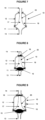
- Figure 7 illustrates the chamber for artificial circulatory assistance object of the present invention when applied as a damping device of the arterial pulse wave.
- a pulsation dampener acts absorbing pressure peaks generated by the pump and, thus, it allows to smooth the pressure curve, stabilizing flow oscillations, producing constant and linear hydraulic flow.
- it is formed by a volume chamber assembled adjoined to the hydraulic piping, it has an inner space to absorb volume and pressure. This inner space is filled with a determined gas volume insulated by means of a resilient membrane.
- a pressure variation in hydraulic circuit during the pumping acts on the chamber and generates the compression of its air volume during the pressure peak produced by the pump, this makes the chamber to retain part of the flow volume generated by the pumping during the pressure peak, inner air from the chamber is compressed and, consequently, builds up pressure. This pressure will be returned to the circuit in the pump aspiration phase, during the pumping cycle when the circuit pressure becomes lower than the pressure accumulated by the compressed air.
- the gases thermodynamic set forth that "when the gas is compressed by an external pressure, the means loses energy and the system gains it, at the same time, when it expands against the external pressure of the means, it spends energy in the work form to achieve the expansion. In this case, the system loses energy and, according to the principle of energy conservation, the means gains the same amount".
- This concept is applied to devices commercially available to be used in various volumetric displacement driving pumping circuits. But there is no use in medical purposes, in medical devices field.
- the vascular system is extensible, i.e., it has the ability to accommodate more blood volume in its compartment through muscular tonus variation, in the arteries it allows the accommodation of the heart pulsatile debt, making the pressure peak being relieved and the blood flow to the little vessels to be continuous and uniform with minimal pulses, this attribute is the Compliance.
- the arterial compliance reduces with the ageing that enhances the effects of hypertension. As smaller is the arterial system compliance, bigger is going to be the elevation of the pressure for a given systolic volume.
- the hypertension is a polygenic syndrome and comprises genetic, environmental, vascular, hormonal, renal and neural aspects.
- the essential or primary arterial hypertension (HA) is one of the most common causes of cardiovascular diseases, affecting nearly 20% of the adult population in industrialized societies.
- the disease is a risk factor for coronary disease development; it accelerates atherosclerosis development and could be a determining factor for the early onset of cardiovascular morbidity and mortality associated to the coronary disease, congestive heart failure, cerebrovascular accident and end-stage renal failure.
- the therapy for arterial hypertension is the reduction of cardiovascular morbidity and mortality, generally, the blood pressure values to be reached as a treatment are: AP ⁇ 140/90 mmHg in general population and AP ⁇ 130/80 mmHg for diabetic hypertensive patients or patients suffering from nephropathy.
- AP ⁇ 140/90 mmHg in general population
- AP ⁇ 130/80 mmHg for diabetic hypertensive patients or patients suffering from nephropathy.
- non-pharmacological and pharmacological measures are applied.
- hypertension is classified as resistant.
- the percutaneous approach for the bilateral renal sympathetic denervation (RSD) using ablation procedure for radiofrequency has been used as an available therapeutic strategy and it is based on the knowledge that, among the various pathophysiological mechanisms involved in the resistance to the control of HA, it is highlighted that the excessive stimulation of the renal sympathetic nervous system.
- the percutaneous interventionist technique named renal sympathetic denervation (RSD) using a catheter coupled to a radiofrequency device is used. This type of device produces radiofrequency shots that are applied to the renal artery wall through a catheter.
- RSD renal sympathetic denervation
- This type of device produces radiofrequency shots that are applied to the renal artery wall through a catheter.
- Several models of these devices have been developed to perform RSD, but because the lack of broader studies about the cost effectiveness of the procedure, its application in large scale shall not be recommended and shall be indicated only for true resistant hypertensive patients, group presenting a very high cardiovascular risk.
- the configuration of the chamber for artificial circulatory assistance object of the present invention comprises a rigid capsule (10), preferably made in transparent polycarbonate having a base (11) and a dome (12), preferably with external concave walls, said dome (12) provided with blood inlet connectors (13) and blood outlet connectors (14) and said inlet (13) and outlet (14) connectors positioned in series.
- the chamber for artificial circulatory assistance comprises an impermeable membrane (20) that divides in two compartments the rigid capsule interior (10), being one blood compartment (17), internal space wherein the blood flows, and the other an external compartment (18) that is filled with gaseous volume.
- the blood flow runs through the blood compartment (17) of the membrane (20) and transmits pressure and volume to the external compartment (18) that is in the periphery, reproducing, this way, two attributes of the vascular system, extensibility and aortic capacitance.
- the chamber for artificial circulatory assistance object of the present invention is implantable and can be removed, differently from the treatment with RSD that promotes permanent injury in the renal artery innervation, as well as sympathectomy. Furthermore, the chamber for artificial circulatory assistance object of the present invention promotes the following effects and advantages: (i) optimizes the vascular extensibility and aortic capacitance when damping systolic pressure peak and absorbing blood volume, (ii) increases diastolic pressure - in diastole the chamber releases the volume and pressure absorbed during systole for circulation, (iii) minimizes the peripheral vascular resistance, (iv) minimizes the blood pressure, (v) minimizes the heart post charge work, (vi) increases the cardiac debt.
- the chamber for artificial circulatory assistance object of the present invention when providing the effects above cited, reduces the risk of occurring complications inherent to the disease, such as cerebrovascular accident (CVA), acute myocardial infarction (AMI) and other morbidity states, still reducing the mortality rate associated to arterial hypertension.
- CVA cerebrovascular accident
- AMI acute myocardial infarction
- other morbidity states still reducing the mortality rate associated to arterial hypertension.
- the chamber for artificial circulatory assistance object of the present invention reproduces the reciprocating pumping such as the heart, and the inlet and outlet one-way valves work to assure the pulsatile flow with systolic and diastolic phases.
- the cycle is generated by driving the external pneumatic device configured to insufflate and deflate the pneumatic compartment of the said chamber.
- the chamber for artificial circulatory assistance comprises the same rigid capsule (10), preferably made in transparent polycarbonate and cylindrical body, base (11) and dome (12), preferably with external concave walls, provided with blood inlet connectors (13) and blood outlet connectors (14) positioned in series, and further the said chamber provided with respective one-way valves (15, 16).
- the chamber for artificial circulation assistance also comprises an impermeable membrane (20) that divides in two compartments the internal rigid capsule (10), one blood compartment (17), inner space wherein the blood flows, and the other external compartment (18) that is filled with compressible gaseous volume, which varies in two defined volumes and alternated occurrence, said objective is providing, in each cycle, the filling the emptying of the said rigid capsule (10).
- the chamber for artificial circulatory assistance thus introduces into the extracorporeal circulation, several advantages still not reached by those from the prior art, which are (i) it is a device that simulates the circulatory physiology, applying the concept of active pulsatile flow associated to the counterpulsation concept, (ii) its application decreases the extracorporeal circuit tubes length, contributing to reduce blood hemodilution, (iii) produces less hemolysis, (iv) eliminates the effects produced by the use of linear flow.
- the chamber for artificial circulatory assistance object of the present invention can be applied as a special blood pumping device wherein makes use of part of the energy from the arterial pulse wave for generating optimized diastolic arterial flow in opposite direction to the systolic arterial flow.
- the compressible gas that fills the external compartment (18) is compressed by the interaction between the pressure variance from the two sides of the membrane (20) and the work of the one-way valves (15, 16) assembled in series produces kinetic movement of the blood.
- diastolic counter flow i.e., blood volume accumulated in the systolic phase in the compressible compartment is restored by the same access during the circulation diastolic phase.
- the pumping flow takes place intermittently and in opposite direction to the arterial flow, occurring directly in the diastolic period using volume and pressure accumulated by the chamber in the systolic period.
- the "counter flow” has sufficient intensity to offer circulatory assistance required for dialythical treatment, ultrafiltration and ventilatory assistance. For doing so, it has to be installed in arterial access, preferably femoral arterial, considering the amplitude of the pulse wave from this artery.
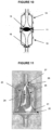
- the chamber for artificial circulatory assistance object of the present invention could also assume a second structural setting, such as the setting illustrated in Figure 9 , when applied as ventricular assistance device, by partial or total substitution of the blood pumping function in patients with poor heart function and indicated for mechanical circulatory assistance treatment.
- the chamber for artificial circulatory assistance object of the present invention comprises the same rigid capsule (10) preferably made of transparent polycarbonate and cylindrical body, base (11) and dome (12) with external concave walls, provided with blood inlet connectors (13) and blood outlet connectors (14), besides the respective one-way valves (15, 16), said inlet (13) and outlet (14) connectors being positioned in series.
- said chamber comprises an impermeable membrane (20) that divides in two compartments the rigid capsule (10) interior, being one blood compartment (17), internal space wherein the blood flows, and the other an external compartment (18) that is filled with gaseous volume or injectable/exhaustible fluid.
- the gas or fluid is compressed by an external device connected to a perpendicular inlet (19) through a proper connector.
- the interaction between pressure variation from the two sides of the membrane, i.e., the blood compartment (17) and external compressible compartment (18) together with the one-way valves (15, 16) functioning assembled in series produces the kinetic movement similar to the physiological cardiac blood flow.
- the blood comes to the chamber for artificial circulatory assistance through the base (11) as to the function of negative pressure generated by the fast removal of gas/fluid from the external compressible compartment (18).
- the chamber fills, the pressure equals and the one-way valve (15) of the base (11) closes.
- the external device delivers a determined volume of gas/fluid into the external compressible compartment (18), the gas is compressed and transfers pressure to the blood.
- the one-way outlet valve (16) in the dome (12) opens allowing blood output. When the internal and external pressure to the chamber is equal, the one-way outlet valve (16) closes restarting the cycle.
- the chamber for artificial circulatory assistance object of the present invention simulates the circulatory physiology, applying an active pulsatile flow concept associated to the counterpulsation concept.
- the work of heart muscle contraction is well reduced (post charge) with the acting of the passive chamber when maximizing the aortic compliance and "assisting" the cardiac systole.
- assistance is very pertinent, because in the ventricular ejection moment that corresponds to the point of myocardial greater effort, the myocardial has to produce required strength for ejecting a given blood volume against a highly resistant compartment.
- the chamber for artificial circulatory assistance object of the present invention acts reducing the peripheral vascular resistance by emptying its air part and, at the same time, facilitates the ventricular ejection.
- the heart is kept in a relative rest state with low energetic spent and low oxygen consumption.
- the chamber for artificial circulatory assistance object of the present invention right after the cardiac cycle, produces an increase in diastolic pressure by filling its air compartment. This effect produces greater cardiac debt and, thus, greater tissue perfusion.
- the chamber for artificial circulatory assistance object of the present invention is compact, with little volume, it can be implemented in paracorporeal or intracavity mode, it is connected to an external drive by means of a compressed air line of variable extension. It is equipped with one-way valves, preferably of "cartwheel” type, which is characterized by a flow passage between its radiuses. This characteristic allows the blood flow without circulation stagnation points, phenomenon faced by other devices equipped with semilunar valves and it has as a consequence the formation and release of blood clots in the circulation.
- the chamber for artificial circulatory assistance object of the present invention produces less blood trauma, because it does not submit the blood flow to high rotations and does not require physical assistance of a clinical perfusionist at the bedside.
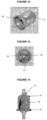
- the chamber for artificial circulatory assistance object of the present invention could also assume a third structural setting, such as the setting illustrated in Figure 10 , when applied as a ventricular assistance device, by partial or total substitution of the blood pumping function in patients with poor heart function and indicated for mechanical circulatory assistance treatment.
- the chamber for artificial assistance object of the present invention comprises two rigid capsules (10, 10') interconnected in series through the bases (11), but incorporating a single one-way inlet valve (15) and a single one-way outlet valve (16).
- the present invention refers, particularly, to a membrane according illustration in Figures 11 to 13 . It is observed in these figures that the membrane (20) comprises a circular base (21) with a flap (22) for adapting in the capsule (10), from where it projects upwards the body (23) which narrows forming vertical alternated indentations (24) and edges (25) up to its superior end (26) wherein it has flap (27) for adapting in the opposite end of said capsule (10).
- the membrane (20) must perfectly engage into the capsule (10) interior in a fixed and hermetic manner, being made of completely impermeable material.
- Said membrane could be, obviously, used in other types of different capsules of the capsule (10), depending only on aspects related to specific projects and uses, because of that it could assume various shapes, since its specific intrinsic characteristics are preserved, such as the ones herein described.
- FIG 14 An example of a variant form falling outside the scope of the claims but of interest for illustrative purposes is the one illustrated in Figure 14 , developed to be applied in a chamber acting under negative pressure, which is especially adequate to be applied in the pump inlet line in order to reduce pressure oscillations.
- said membrane also has a circular base with a flap (22) and the superior end having the flap (27) in such a way that can be perfectly engaged into the chamber interior shaped as a capsule (10), in a fixed and hermetic manner.
- said membrane has a general profile of regular dome (30) that extends upwards in rocket shape.
Landscapes
- Health & Medical Sciences (AREA)
- Heart & Thoracic Surgery (AREA)
- Engineering & Computer Science (AREA)
- Cardiology (AREA)
- Mechanical Engineering (AREA)
- Life Sciences & Earth Sciences (AREA)
- Biomedical Technology (AREA)
- Hematology (AREA)
- Anesthesiology (AREA)
- Animal Behavior & Ethology (AREA)
- General Health & Medical Sciences (AREA)
- Public Health (AREA)
- Veterinary Medicine (AREA)
- Pulmonology (AREA)
- Vascular Medicine (AREA)
- General Engineering & Computer Science (AREA)
- External Artificial Organs (AREA)
- Prostheses (AREA)
Claims (9)
- Membran für eine Fluidzirkulationskammer, umfassend eine kreisförmige Basis (21) mit einer Befestigungsklappe (22), wobei sie aufwärts des Körpers (23) projiziert, gekennzeichnet durch die Membran, die sich kontinuierlich verengt, vertikale Vertiefungen (24) und Kanten (25) ausbildet, die bis zu ihrem oberen Ende (26) alternieren, wobei sie eine Klappe (27) zum Befestigen ihres gegenüberliegenden Endes aufweist.
- Membran nach Anspruch 1, gekennzeichnet durch Vorgesehensein, in das Innere einer Kapsel (10) auf eine feste und hermetische Weise vollkommen in Eingriff gebracht zu werden.
- Kammer für eine künstliche Kreislaufunterstützung, die als eine arterielle Impulswellendämpfungsvorrichtung verwendet werden soll, umfassend einen Körper, der eine Basis (11) und eine Kuppel (12) aufweist, die mit dem Bluteinlass(13)-Verbinder und dem Blutauslass(14)-Verbinder versehen ist, die in Reihe positioniert sind, wobei die Kammer intern eine undurchlässige Membran (20) umfasst, die das Innere der starren Kapsel (10) in zwei Abteilungen teilt, wobei eine eine Blutabteilung (17) und die andere eine externe komprimierbare Abteilung (18) ist, die mit gasförmigem Volumen gefüllt ist, wobei die Membran (20) eine kreisförmige Basis (21) mit einer Befestigungsklappe (22) umfasst, wobei sie aufwärts des Körpers (23) projiziert, gekennzeichnet durch die Membran, die sich kontinuierlich verengt, vertikale Vertiefungen (24) und Kanten (25) ausbildet, die bis zu ihrem oberen Ende (26) alternieren, wobei sie eine Klappe (27) zum Befestigen ihres gegenüberliegenden Endes aufweist.
- Kammer für die künstliche Kreislaufunterstützung nach Anspruch 3, gekennzeichnet durch die Tatsache, dass das gasförmige Volumen innerhalb der externen komprimierbaren Abteilung (18) in zwei definierten Volumina variiert und ein abwechselndes Auftreten aufweist, die die Füllung und das Entleeren der starren Kapsel (10) in jedem Zyklus bereitstellen.
- Kammer für die künstliche Kreislaufunterstützung nach Anspruch 4, gekennzeichnet durch die Wechselwirkung zwischen der Druckvariation auf beiden Seiten der undurchlässigen Membran (20) nach den Ansprüchen 1 bis 4 und das Funktionieren der Einwegventile (15, 16), die in Reihe montiert sind, eine kinetische Bewegung erzeugt, die dem physiologischen Herzblutfluss ähnlich ist.
- Kammer für die künstliche Kreislaufunterstützung, insbesondere in einer vorläufigen oder definitiven implantierbaren medizinischen Vorrichtung zum Wirken als eine kardiovaskuläre Orthese oder Prothese, besonders für den extrakorporalen Kreislauf, umfassend eine starre Kapsel (10) eines zylindrischen Körpers, eine Basis (11) und eine Kuppel (12), die mit dem Bluteinlass(13)-Verbinder und dem Blutauslass(14)-Verbinder versehen sind, und intern Einwegventile (15, 16) aufweist, wobei der Einlass(13)-Verbinder und der Auslass(14)-Verbinder in Reihe positioniert sind und die Kammer ferner umfassend, intern, eine undurchlässige Membran (20), die die starre Kapsel (10) in zwei Abteilungen teilt, wobei eine eine Blutabteilung (17) und die andere eine externe Abteilung (18) ist, die mit komprimierbaren gasförmigen Volumen gefüllt ist, wobei die Membran (20) eine kreisförmige Basis (21) mit einer Befestigungsklappe (22) umfasst, wobei sie aufwärts des Körpers (23) projiziert, gekennzeichnet durch die Membran, die sich kontinuierlich verengt, vertikale Vertiefungen (24) und Kanten (25) ausbildet, die bis zu ihrem oberen Ende (26) alternieren, wobei sie eine Klappe (27) zum Befestigen ihres gegenüberliegenden Endes aufweist.
- Kammer für die künstliche Kreislaufunterstützung, die als eine ventrikuläre Unterstützungsvorrichtung verwendet werden soll, umfassend einen Körper, der eine Basis (11) und eine Kuppel (12) aufweist, die mit dem Bluteinlass(13)-Verbinder und dem Blutauslass(14)-Verbinder versehen ist, die in Reihe positioniert sind, und jeweilige Einwegventile (15, 16), wobei die Kammer intern eine undurchlässige Membran (20) umfasst, die das Innere der starren Kapsel (10) in zwei Abteilungen teilt, wobei eine eine Blutabteilung (17) und die andere eine externe komprimierbare Abteilung (18) ist, die durch eine externe Vorrichtung, die mit einem Einlass (19) verbunden ist, durch einen geeigneten Verbinder hindurch mit gasförmigem Volumen oder injizierbaren/erschöpfbaren Fluid gefüllt ist, wobei die Membran (20) eine kreisförmige Basis (21) mit einer Befestigungsklappe (22) umfasst, wobei sie aufwärts des Körpers (23) projiziert, gekennzeichnet durch die Membran, die sich kontinuierlich verengt, vertikale Vertiefungen (24) und Kanten (25) ausbildet, die bis zu ihrem oberen Ende (26) alternieren, wobei sie eine Klappe (27) zum Befestigen ihres gegenüberliegenden Endes aufweist.
- Kammer für die künstliche Kreislaufunterstützung nach Anspruch 7, gekennzeichnet durch Umfassen von zwei starren Kapseln (10, 10'), die durch die Basen (11) hindurch in Reihe miteinander verbunden sind, aber nur ein einziges Einwegeinlassventil (15) und ein einziges Einwegauslassventil (16) beinhalten.
- Kammer für die künstliche Kreislaufunterstützung der Ansprüche 3 bis 8, gekennzeichnet durch die Tatsache, dass die starre Kapsel (10, 10') aus transparentem Polycarbonat hergestellt ist.
Applications Claiming Priority (1)
| Application Number | Priority Date | Filing Date | Title |
|---|---|---|---|
| PCT/BR2014/000166 WO2015179929A1 (pt) | 2014-05-26 | 2014-05-26 | Câmara para assistência circulatória artificial e membrana |
Publications (3)
| Publication Number | Publication Date |
|---|---|
| EP3153189A1 EP3153189A1 (de) | 2017-04-12 |
| EP3153189A4 EP3153189A4 (de) | 2018-04-18 |
| EP3153189B1 true EP3153189B1 (de) | 2023-08-23 |
Family
ID=54697740
Family Applications (1)
| Application Number | Title | Priority Date | Filing Date |
|---|---|---|---|
| EP14892957.3A Active EP3153189B1 (de) | 2014-05-26 | 2014-05-26 | Kammer für künstliche kreislaufunterstützung und membran |
Country Status (4)
| Country | Link |
|---|---|
| US (1) | US11052179B2 (de) |
| EP (1) | EP3153189B1 (de) |
| BR (1) | BR112016026350A2 (de) |
| WO (1) | WO2015179929A1 (de) |
Families Citing this family (15)
| Publication number | Priority date | Publication date | Assignee | Title |
|---|---|---|---|---|
| BR102016022713A2 (pt) | 2016-09-29 | 2018-05-02 | Zammi Instrumental Ltda | Membrana para câmara de circulação de fluidos, câmara e bomba para assistência circulatória artificial e sistema de bombeamento |
| CA3066361A1 (en) | 2017-06-07 | 2018-12-13 | Shifamed Holdings, Llc | Intravascular fluid movement devices, systems, and methods of use |
| BR102017021552A2 (pt) * | 2017-10-06 | 2019-04-24 | Zammi Instrumental Ltda | Processo de recuperação de sangue residual de circuito de circulação extracorpórea e equipamento de coleta e recuperação de sangue residual de circuito de circulação extracorpórea |
| CN111556763B (zh) | 2017-11-13 | 2023-09-01 | 施菲姆德控股有限责任公司 | 血管内流体运动装置、系统 |
| EP3746149B1 (de) | 2018-02-01 | 2025-08-06 | Shifamed Holdings, LLC | Intravaskuläre blutpumpen |
| WO2020028537A1 (en) | 2018-07-31 | 2020-02-06 | Shifamed Holdings, Llc | Intravascaular blood pumps and methods of use |
| EP3860675A4 (de) | 2018-10-05 | 2022-07-13 | Shifamed Holdings, LLC | Intravaskuläre blutpumpen und verfahren zur verwendung |
| JP2022540616A (ja) | 2019-07-12 | 2022-09-16 | シファメド・ホールディングス・エルエルシー | 血管内血液ポンプならびに製造および使用の方法 |
| WO2021016372A1 (en) | 2019-07-22 | 2021-01-28 | Shifamed Holdings, Llc | Intravascular blood pumps with struts and methods of use and manufacture |
| WO2021026473A1 (en) | 2019-08-07 | 2021-02-11 | Calomeni Michael | Catheter blood pumps and collapsible pump housings |
| WO2021062260A1 (en) | 2019-09-25 | 2021-04-01 | Shifamed Holdings, Llc | Catheter blood pumps and collapsible blood conduits |
| EP4501393A3 (de) | 2019-09-25 | 2025-04-09 | Shifamed Holdings, LLC | Katheterblutpumpen und zusammenklappbare pumpengehäuse |
| EP4034192A4 (de) | 2019-09-25 | 2023-11-29 | Shifamed Holdings, LLC | Intravaskuläre blutpumpensysteme und verfahren zur verwendung und steuerung davon |
| EP4072650A4 (de) | 2019-12-11 | 2024-01-10 | Shifamed Holdings, LLC | Absteigende aorten- und hohlvenenblutpumpen |
| CN111330103A (zh) * | 2020-03-10 | 2020-06-26 | 中国医科大学附属第一医院 | 一种智能血流动力学辅助器械 |
Family Cites Families (13)
| Publication number | Priority date | Publication date | Assignee | Title |
|---|---|---|---|---|
| US3453967A (en) * | 1967-09-15 | 1969-07-08 | Electro Medical Systems Inc | Pump |
| US3883272A (en) * | 1973-04-16 | 1975-05-13 | Benjamin V Puckett | Hydraulic pump with replaceable pumping member |
| US4104005A (en) * | 1976-01-09 | 1978-08-01 | Thermo Electron Corporation | Pneumatic bladder pump having stiffness symmetry |
| US4077882A (en) * | 1976-09-27 | 1978-03-07 | Ronald Gangemi | Isolating and blood pressure transmitting apparatus for extracorporeal blood treatment system |
| US4938766A (en) * | 1987-08-28 | 1990-07-03 | Jarvik Robert K | Prosthetic compliance devices |
| US6877713B1 (en) * | 1999-07-20 | 2005-04-12 | Deka Products Limited Partnership | Tube occluder and method for occluding collapsible tubes |
| IT1311348B1 (it) * | 1999-11-12 | 2002-03-12 | Borla Ind | Valvola di ritegno per linee medicali di infusione e simili. |
| US6497675B1 (en) * | 2000-04-17 | 2002-12-24 | Renal Tech International Llc | Device for extracorporeal treatment of physiological fluids of organism |
| MX342685B (es) * | 2000-10-12 | 2016-10-07 | Renal Solutions Inc | Dispositivos y metodos para el control de flujo de fluidos corporales en tratamientos de fluidos fuera del cuerpo. |
| GB2371230B (en) * | 2001-02-08 | 2002-10-16 | Tayside Flow Technologies Ltd | Pumps |
| US6607368B1 (en) * | 2001-11-03 | 2003-08-19 | Anthony Ross | Linear pump and method |
| ITMI20021028A1 (it) * | 2002-05-14 | 2003-11-14 | Dideco Spa | Unita' pompante di fluido in particolare sangue |
| ES2364516B1 (es) * | 2010-02-25 | 2012-09-26 | Salvador Merce Vives | Equipo de pulsación hidráulica aplicable a una bomba de perfusión. |
-
2014
- 2014-05-26 EP EP14892957.3A patent/EP3153189B1/de active Active
- 2014-05-26 BR BR112016026350A patent/BR112016026350A2/pt not_active Application Discontinuation
- 2014-05-26 WO PCT/BR2014/000166 patent/WO2015179929A1/pt not_active Ceased
- 2014-05-26 US US15/314,036 patent/US11052179B2/en active Active
Also Published As
| Publication number | Publication date |
|---|---|
| EP3153189A1 (de) | 2017-04-12 |
| WO2015179929A1 (pt) | 2015-12-03 |
| US20170112984A1 (en) | 2017-04-27 |
| EP3153189A4 (de) | 2018-04-18 |
| US11052179B2 (en) | 2021-07-06 |
| BR112016026350A2 (pt) | 2017-05-30 |
Similar Documents
| Publication | Publication Date | Title |
|---|---|---|
| EP3153189B1 (de) | Kammer für künstliche kreislaufunterstützung und membran | |
| US20240285930A1 (en) | Fluid circulation chamber membrane, a chamber and pump for artificial circulatory assistance and a pumping system | |
| JP7637664B2 (ja) | 非閉鎖型血液ポンプの制御ユニット | |
| JP5868180B2 (ja) | 体外手術において使用されるように設計された拍動型医療デバイス | |
| EP1482999A4 (de) | Physiologisch kompatible vorrichtung zur unterstützung des herzens und verfahren | |
| WO2025011166A1 (zh) | 左心室辅助装置 | |
| US9937287B2 (en) | Pulsatile medical device designed to be used in extracorporeal surgery | |
| Li et al. | Simulation study of the Hemopump as a cardiac assist device | |
| CN1095383C (zh) | 辅助循环导流反搏急救装置 | |
| BR112019002367B1 (pt) | Bomba para assistência circulatória artificial e sistema de bombeamento | |
| Khodeli et al. | Practical and Theoretical Considerations for ECMO System Development | |
| RU202952U1 (ru) | Устройство управления потоком крови в имплантируемых системах вспомогательного кровообращения | |
| Waaben et al. | Pulsatile flow during cardiopulmonary bypass: Evaluation of a new pulsatile pump | |
| RU210252U1 (ru) | Устройство управления потоком крови в экстракорпоральных системах вспомогательного кровообращения | |
| Moores et al. | Mechanical support of the circulation by a modified pulsatile roller pump | |
| Goldfarb | Mechanical circulatory assistance in the treatment of cardiac failure | |
| Coutrot et al. | Hemodynamics and Extracorporeal Circulation | |
| Madan et al. | Cardiac Assist Devices | |
| Kuleshov et al. | Comparison of Pulsatile Blood Flows by Rotor Speed Modulation and Use of an Autonomous Pulsator | |
| Madan et al. | 3. Extracorporeal membrane oxygenation (ECMO) | |
| Imanishi et al. | A percutaneously accessible pulsatile left ventricular assist device: modified assist device type 5 | |
| Coutrot et al. | Principles of VA-ECMO Circulatory Support–118 Macrohemodynamics Under VA-ECMO–118 | |
| CN119424897A (zh) | 一种用于循环辅助的导管装置及循环辅助系统 | |
| Koenig et al. | Hemodynamic and left ventricular pressure-volume responses to counterpulsation in mock circulation and acute large animal models | |
| Nakata et al. | The Hemodynamics of Cardiac Tamponade: Symposium III Pericarditis |
Legal Events
| Date | Code | Title | Description |
|---|---|---|---|
| STAA | Information on the status of an ep patent application or granted ep patent |
Free format text: STATUS: THE INTERNATIONAL PUBLICATION HAS BEEN MADE |
|
| PUAI | Public reference made under article 153(3) epc to a published international application that has entered the european phase |
Free format text: ORIGINAL CODE: 0009012 |
|
| STAA | Information on the status of an ep patent application or granted ep patent |
Free format text: STATUS: REQUEST FOR EXAMINATION WAS MADE |
|
| 17P | Request for examination filed |
Effective date: 20161220 |
|
| AK | Designated contracting states |
Kind code of ref document: A1 Designated state(s): AL AT BE BG CH CY CZ DE DK EE ES FI FR GB GR HR HU IE IS IT LI LT LU LV MC MK MT NL NO PL PT RO RS SE SI SK SM TR |
|
| AX | Request for extension of the european patent |
Extension state: BA ME |
|
| DAX | Request for extension of the european patent (deleted) | ||
| A4 | Supplementary search report drawn up and despatched |
Effective date: 20180321 |
|
| RIC1 | Information provided on ipc code assigned before grant |
Ipc: A61M 1/12 20060101ALI20180315BHEP Ipc: A61M 1/10 20060101AFI20180315BHEP |
|
| STAA | Information on the status of an ep patent application or granted ep patent |
Free format text: STATUS: EXAMINATION IS IN PROGRESS |
|
| 17Q | First examination report despatched |
Effective date: 20220405 |
|
| REG | Reference to a national code |
Ref country code: DE Ref legal event code: R079 Free format text: PREVIOUS MAIN CLASS: A61M0001100000 Ipc: A61M0060113000 Ref country code: DE Ref legal event code: R079 Ref document number: 602014088059 Country of ref document: DE Free format text: PREVIOUS MAIN CLASS: A61M0001100000 Ipc: A61M0060113000 |
|
| GRAP | Despatch of communication of intention to grant a patent |
Free format text: ORIGINAL CODE: EPIDOSNIGR1 |
|
| STAA | Information on the status of an ep patent application or granted ep patent |
Free format text: STATUS: GRANT OF PATENT IS INTENDED |
|
| RIC1 | Information provided on ipc code assigned before grant |
Ipc: F04B 43/08 20060101ALI20230131BHEP Ipc: A61M 60/896 20210101ALI20230131BHEP Ipc: A61M 60/869 20210101ALI20230131BHEP Ipc: A61M 60/894 20210101ALI20230131BHEP Ipc: A61M 60/837 20210101ALI20230131BHEP Ipc: A61M 60/43 20210101ALI20230131BHEP Ipc: A61M 60/268 20210101ALI20230131BHEP Ipc: A61M 60/178 20210101ALI20230131BHEP Ipc: A61M 60/122 20210101ALI20230131BHEP Ipc: A61M 60/117 20210101ALI20230131BHEP Ipc: A61M 60/113 20210101AFI20230131BHEP |
|
| INTG | Intention to grant announced |
Effective date: 20230307 |
|
| GRAS | Grant fee paid |
Free format text: ORIGINAL CODE: EPIDOSNIGR3 |
|
| GRAA | (expected) grant |
Free format text: ORIGINAL CODE: 0009210 |
|
| STAA | Information on the status of an ep patent application or granted ep patent |
Free format text: STATUS: THE PATENT HAS BEEN GRANTED |
|
| AK | Designated contracting states |
Kind code of ref document: B1 Designated state(s): AL AT BE BG CH CY CZ DE DK EE ES FI FR GB GR HR HU IE IS IT LI LT LU LV MC MK MT NL NO PL PT RO RS SE SI SK SM TR |
|
| REG | Reference to a national code |
Ref country code: GB Ref legal event code: FG4D |
|
| REG | Reference to a national code |
Ref country code: CH Ref legal event code: EP |
|
| REG | Reference to a national code |
Ref country code: IE Ref legal event code: FG4D |
|
| REG | Reference to a national code |
Ref country code: DE Ref legal event code: R096 Ref document number: 602014088059 Country of ref document: DE |
|
| REG | Reference to a national code |
Ref country code: LT Ref legal event code: MG9D |
|
| REG | Reference to a national code |
Ref country code: NL Ref legal event code: MP Effective date: 20230823 |
|
| REG | Reference to a national code |
Ref country code: AT Ref legal event code: MK05 Ref document number: 1601864 Country of ref document: AT Kind code of ref document: T Effective date: 20230823 |
|
| PG25 | Lapsed in a contracting state [announced via postgrant information from national office to epo] |
Ref country code: GR Free format text: LAPSE BECAUSE OF FAILURE TO SUBMIT A TRANSLATION OF THE DESCRIPTION OR TO PAY THE FEE WITHIN THE PRESCRIBED TIME-LIMIT Effective date: 20231124 |
|
| PG25 | Lapsed in a contracting state [announced via postgrant information from national office to epo] |
Ref country code: IS Free format text: LAPSE BECAUSE OF FAILURE TO SUBMIT A TRANSLATION OF THE DESCRIPTION OR TO PAY THE FEE WITHIN THE PRESCRIBED TIME-LIMIT Effective date: 20231223 |
|
| PG25 | Lapsed in a contracting state [announced via postgrant information from national office to epo] |
Ref country code: SE Free format text: LAPSE BECAUSE OF FAILURE TO SUBMIT A TRANSLATION OF THE DESCRIPTION OR TO PAY THE FEE WITHIN THE PRESCRIBED TIME-LIMIT Effective date: 20230823 Ref country code: RS Free format text: LAPSE BECAUSE OF FAILURE TO SUBMIT A TRANSLATION OF THE DESCRIPTION OR TO PAY THE FEE WITHIN THE PRESCRIBED TIME-LIMIT Effective date: 20230823 Ref country code: PT Free format text: LAPSE BECAUSE OF FAILURE TO SUBMIT A TRANSLATION OF THE DESCRIPTION OR TO PAY THE FEE WITHIN THE PRESCRIBED TIME-LIMIT Effective date: 20231226 Ref country code: NO Free format text: LAPSE BECAUSE OF FAILURE TO SUBMIT A TRANSLATION OF THE DESCRIPTION OR TO PAY THE FEE WITHIN THE PRESCRIBED TIME-LIMIT Effective date: 20231123 Ref country code: NL Free format text: LAPSE BECAUSE OF FAILURE TO SUBMIT A TRANSLATION OF THE DESCRIPTION OR TO PAY THE FEE WITHIN THE PRESCRIBED TIME-LIMIT Effective date: 20230823 Ref country code: LV Free format text: LAPSE BECAUSE OF FAILURE TO SUBMIT A TRANSLATION OF THE DESCRIPTION OR TO PAY THE FEE WITHIN THE PRESCRIBED TIME-LIMIT Effective date: 20230823 Ref country code: LT Free format text: LAPSE BECAUSE OF FAILURE TO SUBMIT A TRANSLATION OF THE DESCRIPTION OR TO PAY THE FEE WITHIN THE PRESCRIBED TIME-LIMIT Effective date: 20230823 Ref country code: IS Free format text: LAPSE BECAUSE OF FAILURE TO SUBMIT A TRANSLATION OF THE DESCRIPTION OR TO PAY THE FEE WITHIN THE PRESCRIBED TIME-LIMIT Effective date: 20231223 Ref country code: HR Free format text: LAPSE BECAUSE OF FAILURE TO SUBMIT A TRANSLATION OF THE DESCRIPTION OR TO PAY THE FEE WITHIN THE PRESCRIBED TIME-LIMIT Effective date: 20230823 Ref country code: GR Free format text: LAPSE BECAUSE OF FAILURE TO SUBMIT A TRANSLATION OF THE DESCRIPTION OR TO PAY THE FEE WITHIN THE PRESCRIBED TIME-LIMIT Effective date: 20231124 Ref country code: FI Free format text: LAPSE BECAUSE OF FAILURE TO SUBMIT A TRANSLATION OF THE DESCRIPTION OR TO PAY THE FEE WITHIN THE PRESCRIBED TIME-LIMIT Effective date: 20230823 Ref country code: AT Free format text: LAPSE BECAUSE OF FAILURE TO SUBMIT A TRANSLATION OF THE DESCRIPTION OR TO PAY THE FEE WITHIN THE PRESCRIBED TIME-LIMIT Effective date: 20230823 |
|
| PG25 | Lapsed in a contracting state [announced via postgrant information from national office to epo] |
Ref country code: PL Free format text: LAPSE BECAUSE OF FAILURE TO SUBMIT A TRANSLATION OF THE DESCRIPTION OR TO PAY THE FEE WITHIN THE PRESCRIBED TIME-LIMIT Effective date: 20230823 |
|
| PG25 | Lapsed in a contracting state [announced via postgrant information from national office to epo] |
Ref country code: ES Free format text: LAPSE BECAUSE OF FAILURE TO SUBMIT A TRANSLATION OF THE DESCRIPTION OR TO PAY THE FEE WITHIN THE PRESCRIBED TIME-LIMIT Effective date: 20230823 |
|
| PG25 | Lapsed in a contracting state [announced via postgrant information from national office to epo] |
Ref country code: SM Free format text: LAPSE BECAUSE OF FAILURE TO SUBMIT A TRANSLATION OF THE DESCRIPTION OR TO PAY THE FEE WITHIN THE PRESCRIBED TIME-LIMIT Effective date: 20230823 Ref country code: RO Free format text: LAPSE BECAUSE OF FAILURE TO SUBMIT A TRANSLATION OF THE DESCRIPTION OR TO PAY THE FEE WITHIN THE PRESCRIBED TIME-LIMIT Effective date: 20230823 Ref country code: ES Free format text: LAPSE BECAUSE OF FAILURE TO SUBMIT A TRANSLATION OF THE DESCRIPTION OR TO PAY THE FEE WITHIN THE PRESCRIBED TIME-LIMIT Effective date: 20230823 Ref country code: EE Free format text: LAPSE BECAUSE OF FAILURE TO SUBMIT A TRANSLATION OF THE DESCRIPTION OR TO PAY THE FEE WITHIN THE PRESCRIBED TIME-LIMIT Effective date: 20230823 Ref country code: DK Free format text: LAPSE BECAUSE OF FAILURE TO SUBMIT A TRANSLATION OF THE DESCRIPTION OR TO PAY THE FEE WITHIN THE PRESCRIBED TIME-LIMIT Effective date: 20230823 Ref country code: CZ Free format text: LAPSE BECAUSE OF FAILURE TO SUBMIT A TRANSLATION OF THE DESCRIPTION OR TO PAY THE FEE WITHIN THE PRESCRIBED TIME-LIMIT Effective date: 20230823 Ref country code: SK Free format text: LAPSE BECAUSE OF FAILURE TO SUBMIT A TRANSLATION OF THE DESCRIPTION OR TO PAY THE FEE WITHIN THE PRESCRIBED TIME-LIMIT Effective date: 20230823 |
|
| REG | Reference to a national code |
Ref country code: DE Ref legal event code: R097 Ref document number: 602014088059 Country of ref document: DE |
|
| PLBE | No opposition filed within time limit |
Free format text: ORIGINAL CODE: 0009261 |
|
| STAA | Information on the status of an ep patent application or granted ep patent |
Free format text: STATUS: NO OPPOSITION FILED WITHIN TIME LIMIT |
|
| 26N | No opposition filed |
Effective date: 20240524 |
|
| PG25 | Lapsed in a contracting state [announced via postgrant information from national office to epo] |
Ref country code: SI Free format text: LAPSE BECAUSE OF FAILURE TO SUBMIT A TRANSLATION OF THE DESCRIPTION OR TO PAY THE FEE WITHIN THE PRESCRIBED TIME-LIMIT Effective date: 20230823 |
|
| PG25 | Lapsed in a contracting state [announced via postgrant information from national office to epo] |
Ref country code: BG Free format text: LAPSE BECAUSE OF FAILURE TO SUBMIT A TRANSLATION OF THE DESCRIPTION OR TO PAY THE FEE WITHIN THE PRESCRIBED TIME-LIMIT Effective date: 20230823 |
|
| PG25 | Lapsed in a contracting state [announced via postgrant information from national office to epo] |
Ref country code: BG Free format text: LAPSE BECAUSE OF FAILURE TO SUBMIT A TRANSLATION OF THE DESCRIPTION OR TO PAY THE FEE WITHIN THE PRESCRIBED TIME-LIMIT Effective date: 20230823 |
|
| REG | Reference to a national code |
Ref country code: CH Ref legal event code: PL |
|
| PG25 | Lapsed in a contracting state [announced via postgrant information from national office to epo] |
Ref country code: MC Free format text: LAPSE BECAUSE OF FAILURE TO SUBMIT A TRANSLATION OF THE DESCRIPTION OR TO PAY THE FEE WITHIN THE PRESCRIBED TIME-LIMIT Effective date: 20230823 |
|
| PG25 | Lapsed in a contracting state [announced via postgrant information from national office to epo] |
Ref country code: LU Free format text: LAPSE BECAUSE OF NON-PAYMENT OF DUE FEES Effective date: 20240526 |
|
| PG25 | Lapsed in a contracting state [announced via postgrant information from national office to epo] |
Ref country code: MC Free format text: LAPSE BECAUSE OF FAILURE TO SUBMIT A TRANSLATION OF THE DESCRIPTION OR TO PAY THE FEE WITHIN THE PRESCRIBED TIME-LIMIT Effective date: 20230823 Ref country code: LU Free format text: LAPSE BECAUSE OF NON-PAYMENT OF DUE FEES Effective date: 20240526 Ref country code: CH Free format text: LAPSE BECAUSE OF NON-PAYMENT OF DUE FEES Effective date: 20240531 |
|
| REG | Reference to a national code |
Ref country code: BE Ref legal event code: MM Effective date: 20240531 |
|
| PG25 | Lapsed in a contracting state [announced via postgrant information from national office to epo] |
Ref country code: IE Free format text: LAPSE BECAUSE OF NON-PAYMENT OF DUE FEES Effective date: 20240526 |
|
| PG25 | Lapsed in a contracting state [announced via postgrant information from national office to epo] |
Ref country code: BE Free format text: LAPSE BECAUSE OF NON-PAYMENT OF DUE FEES Effective date: 20240531 |
|
| PGFP | Annual fee paid to national office [announced via postgrant information from national office to epo] |
Ref country code: DE Payment date: 20250528 Year of fee payment: 12 |
|
| PGFP | Annual fee paid to national office [announced via postgrant information from national office to epo] |
Ref country code: GB Payment date: 20250529 Year of fee payment: 12 |
|
| PGFP | Annual fee paid to national office [announced via postgrant information from national office to epo] |
Ref country code: IT Payment date: 20250522 Year of fee payment: 12 |
|
| PGFP | Annual fee paid to national office [announced via postgrant information from national office to epo] |
Ref country code: FR Payment date: 20250527 Year of fee payment: 12 |
|
| PG25 | Lapsed in a contracting state [announced via postgrant information from national office to epo] |
Ref country code: HU Free format text: LAPSE BECAUSE OF FAILURE TO SUBMIT A TRANSLATION OF THE DESCRIPTION OR TO PAY THE FEE WITHIN THE PRESCRIBED TIME-LIMIT; INVALID AB INITIO Effective date: 20140526 |
|
| PG25 | Lapsed in a contracting state [announced via postgrant information from national office to epo] |
Ref country code: CY Free format text: LAPSE BECAUSE OF FAILURE TO SUBMIT A TRANSLATION OF THE DESCRIPTION OR TO PAY THE FEE WITHIN THE PRESCRIBED TIME-LIMIT; INVALID AB INITIO Effective date: 20140526 |