EP3153008A1 - A belt pickup with drive system - Google Patents
A belt pickup with drive system Download PDFInfo
- Publication number
- EP3153008A1 EP3153008A1 EP16188287.3A EP16188287A EP3153008A1 EP 3153008 A1 EP3153008 A1 EP 3153008A1 EP 16188287 A EP16188287 A EP 16188287A EP 3153008 A1 EP3153008 A1 EP 3153008A1
- Authority
- EP
- European Patent Office
- Prior art keywords
- belt
- pulley
- drive
- pickup
- mechanical link
- Prior art date
- Legal status (The legal status is an assumption and is not a legal conclusion. Google has not performed a legal analysis and makes no representation as to the accuracy of the status listed.)
- Granted
Links
Images

Classifications
-
- A—HUMAN NECESSITIES
- A01—AGRICULTURE; FORESTRY; ANIMAL HUSBANDRY; HUNTING; TRAPPING; FISHING
- A01D—HARVESTING; MOWING
- A01D41/00—Combines, i.e. harvesters or mowers combined with threshing devices
- A01D41/10—Field threshers with windrow pick-up apparatus
-
- A—HUMAN NECESSITIES
- A01—AGRICULTURE; FORESTRY; ANIMAL HUSBANDRY; HUNTING; TRAPPING; FISHING
- A01D—HARVESTING; MOWING
- A01D41/00—Combines, i.e. harvesters or mowers combined with threshing devices
- A01D41/12—Details of combines
- A01D41/127—Control or measuring arrangements specially adapted for combines
- A01D41/1274—Control or measuring arrangements specially adapted for combines for drives
-
- A—HUMAN NECESSITIES
- A01—AGRICULTURE; FORESTRY; ANIMAL HUSBANDRY; HUNTING; TRAPPING; FISHING
- A01D—HARVESTING; MOWING
- A01D89/00—Pick-ups for loaders, chaff-cutters, balers, field-threshers, or the like, i.e. attachments for picking-up hay or the like field crops
- A01D89/001—Pick-up systems
- A01D89/003—Endless belts
-
- A—HUMAN NECESSITIES
- A01—AGRICULTURE; FORESTRY; ANIMAL HUSBANDRY; HUNTING; TRAPPING; FISHING
- A01D—HARVESTING; MOWING
- A01D89/00—Pick-ups for loaders, chaff-cutters, balers, field-threshers, or the like, i.e. attachments for picking-up hay or the like field crops
- A01D89/005—Drives
Definitions
- This invention relates to belt pickups for agricultural combines. More particularly it relates to drive systems for belt pickups.
- Belt pickups for agricultural combines are agricultural harvesting heads that gather previously cut crop plants that have been gathered into windrows.
- Belt pickups typically have a pickup conveyor that picks the cut crop up from the ground, a transfer conveyor disposed behind the pickup conveyor that transfers the cut crop material from the pickup conveyor to an auger conveyor, and an auger conveyor that receives the cut crop material from the transfer conveyor, gathers the cut crop material in from the sides of the belt pickup and sends it through a central aperture in the rear of the frame of the belt pickup.
- the cut crop material passing through the central aperture is transmitted to a belt conveyor in the feeder house that extends forward from the front end of an agricultural combine.
- the feeder house conveys the cut crop material into the body of the agricultural combine where it is threshed, separated, cleaned, and the grain portion of the cut crop material is stored in a grain tank.
- a belt pickup with a drive system comprises: a frame; a pickup conveyor supported on the frame, the pickup conveyor comprising a first endless conveyor belt the first endless conveyor belt having a plurality of fingers fixed to the first endless conveyor belt and extending outward from the first endless conveyor belt, wherein the plurality of fingers are disposed to lift cut crop material onto an upper surface of the first endless conveyor belt as the belt pickup travels through the field harvesting crop, and wherein the pickup conveyor further comprises a first drive roller and a first idler roller that support the first endless conveyor belt for recirculating movement about the first drive roller and the first idler roller; a transfer conveyor supported on the frame, wherein the transfer conveyor is disposed behind the pickup conveyor to receive cut crop material therefrom, and wherein the transfer conveyor further comprises a second endless conveyor belt supported for recirculating movement about a second drive roller and a second idler roller; and the drive system comprising a motor coupled to the second drive roller to drive the second drive roller, a first pulley coupled to the motor
- the belt pickup may further comprise a first mechanical link disposed to support the second pulley and the third pulley for free rotation.
- the belt pickup may further comprise a second mechanical link pivotally coupled to the first mechanical link to support the first mechanical link and to permit the first mechanical link to pivot with respect to the second mechanical link.
- the second mechanical link may be pivotally coupled to the frame at a pivot joint to permit the second mechanical link to pivot with respect to the frame.
- the belt pickup may further comprise a spring that is coupled to the frame and is coupled to the second mechanical link to apply a spring force to the second mechanical link and tension the first endless drive belt and the second endless drive belt.
- the second pulley and the third pulley may be fixed to a shaft that extends through a hole formed in a lower end of the first mechanical link.
- the shaft may be supported for free rotation in the hole.
- the first mechanical link and the second mechanical link may be generally disposed at a right angle with respect to each other.
- a belt pickup 100 comprises a frame 102 on which are supported an auger conveyor 104, a pickup conveyor 106, and a transfer conveyor 108 and a drive system 130.
- the pickup conveyor 106 comprises a drive roller 112, an idler roller 114, and an endless conveyor belt 116 to which a plurality of fingers 118 are attached.
- the endless conveyor belt 116 is supported on the drive roller 112 and the idler roller 114 for recirculating movement. As the endless conveyor belt 116 circulates about the rollers, the plurality of fingers 118 engage the cut crop material laying on the ground, pick it up, and deposit it on the upwardly facing surface of the endless conveyor belt 116.
- the endless conveyor belt 116 carries the cut crop material rearward.
- the endless conveyor belt 116 is made of elastomer impregnated fabric.
- the transfer conveyor 108 comprises a drive roller 120, and idler roller 122, and an endless conveyor belt 124.
- the endless conveyor belt 124 is supported on the drive roller 120 and the idler roller 122 for recirculating movement. As the endless conveyor belt 124 circulates about the rollers, the endless conveyor belt 124 receives the cut crop material from the endless conveyor belt 116 of the pickup conveyor 106.
- the endless conveyor belt 124 carries the cut crop material rearward.
- the endless conveyor belt 124 is made of elastomer impregnated fabric.
- the auger conveyor 104 comprises an elongate cylindrical drum 126 supported on the frame 102.
- the elongate cylindrical drum 126 has spiral flights 128 affixed to each end of the cylindrical drum 126.
- the spiral flights 128 draw cut crop material inward to a central region of the frame 102 when the auger conveyor is driven in a direction for harvesting crop.
- the auger conveyor 104 As the auger conveyor 104 rotates, it receives the cut crop material from the endless conveyor belt 124 of the transfer conveyor 108, draws it inward from both sides of the endless conveyor belt 124 to a central region of the elongate cylindrical drum 126, and conveys the cut crop material rearward through a central aperture 110 in the frame 102.
- the central aperture 110 is provided in the rear of the frame 102 to communicate cut crop through the frame 102 and into the feeder house (not shown) of the agricultural combine (not shown) which supports the belt pickup 100.
- the pickup conveyor 106 and the transfer conveyor 108 are coupled to and driven by the drive system 130.
- the drive system 130 comprises a motor 132 coupled to the drive roller 120 to drive the drive roller 120 in rotation, a pulley 134 coupled to the motor 132 to be driven in rotation by the motor 132, an endless drive belt 136 coupled to the pulley 134 to be driven by the pulley 134, a pulley 138 driven in rotation by the endless drive belt 136, a pulley 140 fixed to the pulley 138 to be driven in rotation by the pulley 138, an endless drive belt 142 driven by the pulley 140, and a pulley 144 fixed to the drive roller 112 to drive the drive roller 112 in rotation.
- the motor 132 drives the drive roller 120 directly, and drives the drive roller 112 through a series of endless drive belts and pulleys.
- a mechanism 146 is provided to support the pulley 138 and the pulley 140, and to tension the endless drive belt 136 and the endless drive belt 142 by deflecting the pulley 138 and the pulley 140 upward.
- the tension in the endless drive belt 136 and the endless drive belt 142 increases the friction between the endless drive belts and the pulleys on which they are supported, and therefore permits power to be communicated from the motor 132 to the pulley 144, and thence to the drive roller 112.
- the mechanism 146 comprises a first mechanical link 148.
- the first mechanical link 148 supports a shaft 150 on which the pulley 138 and the pulley 140 are fixed.
- the lower end of the first mechanical link 148 has a hole through which the shaft 150 extends.
- the shaft 150 is free to rotate in the hole.
- the pulley 138 is fixed on one end of the shaft 150 and the pulley 140 is fixed on the other end of the shaft 150.
- the pulley 138 and the pulley 140 are fixed to the shaft 150, and thus rotate together. They are free to rotate with respect to the first mechanical link 148.
- the upper end of the first mechanical link 148 is pivotally coupled to a first end of a second mechanical link 152.
- the first mechanical link 148 is free to pivot with respect to the second mechanical link 152.
- a second end of the second mechanical link 152 is coupled to the frame 102 of the belt pickup 100 at a pivot joint 154.
- the second mechanical link 152 is free to pivot with respect to the frame 102 about the pivot joint 154.
- the first mechanical link 148 and the second mechanical link 152 generally extend at a right angle with respect to each other. Thus, as the second mechanical link 152 pivots about the pivot joint 154, the first mechanical link 148 translates vertically.
- a spring 156 is coupled to the frame 102 of the belt pickup 100 at a first end of the spring 156.
- a second end of the spring 156 is coupled to the second mechanical link 152 at a point between the first end and the second end of the second mechanical link.
- the spring 156 applies an upward force to the second mechanical link 152. This upward force is communicated to the upper end of the first mechanical link 148. The upward force is communicated through the first mechanical link 148, the shaft 150, and the pulley 138 and the pulley 140.
- the upward force lifts the pulley 138 and the pulley 140 until it is resisted by a counteracting tension in the endless drive belt 136 and the endless drive belt 142.
- the counteracting tension in the endless drive belt 136 and the endless drive belt 142 is applied, in turn, to pulley 134 and pulley 144.
Landscapes
- Life Sciences & Earth Sciences (AREA)
- Environmental Sciences (AREA)
- Harvester Elements (AREA)
- Structure Of Belt Conveyors (AREA)
- Devices For Conveying Motion By Means Of Endless Flexible Members (AREA)
Description
- This invention relates to belt pickups for agricultural combines. More particularly it relates to drive systems for belt pickups.
- Belt pickups for agricultural combines are agricultural harvesting heads that gather previously cut crop plants that have been gathered into windrows. Belt pickups typically have a pickup conveyor that picks the cut crop up from the ground, a transfer conveyor disposed behind the pickup conveyor that transfers the cut crop material from the pickup conveyor to an auger conveyor, and an auger conveyor that receives the cut crop material from the transfer conveyor, gathers the cut crop material in from the sides of the belt pickup and sends it through a central aperture in the rear of the frame of the belt pickup.
- The cut crop material passing through the central aperture is transmitted to a belt conveyor in the feeder house that extends forward from the front end of an agricultural combine. The feeder house conveys the cut crop material into the body of the agricultural combine where it is threshed, separated, cleaned, and the grain portion of the cut crop material is stored in a grain tank.
- One problem with this arrangement is that the pickup conveyor and the transfer conveyor are driven by separate hydraulic motors.
- What is needed, therefore, is a drive system for a belt pickup that permits a single motor to efficiently drive both the pickup conveyor and the transfer conveyor.
- In accordance with a first aspect of the invention, a belt pickup with a drive system comprises: a frame; a pickup conveyor supported on the frame, the pickup conveyor comprising a first endless conveyor belt the first endless conveyor belt having a plurality of fingers fixed to the first endless conveyor belt and extending outward from the first endless conveyor belt, wherein the plurality of fingers are disposed to lift cut crop material onto an upper surface of the first endless conveyor belt as the belt pickup travels through the field harvesting crop, and wherein the pickup conveyor further comprises a first drive roller and a first idler roller that support the first endless conveyor belt for recirculating movement about the first drive roller and the first idler roller; a transfer conveyor supported on the frame, wherein the transfer conveyor is disposed behind the pickup conveyor to receive cut crop material therefrom, and wherein the transfer conveyor further comprises a second endless conveyor belt supported for recirculating movement about a second drive roller and a second idler roller; and the drive system comprising a motor coupled to the second drive roller to drive the second drive roller, a first pulley coupled to the motor and driven by the motor, a first endless drive belt coupled to the first pulley and driven by the first pulley, a second pulley coupled to and driven in rotation by the first endless drive belt, a third pulley fixed to the second pulley and driven in rotation by the second pulley, a second endless drive belt coupled to and driven by the third pulley, and a fourth pulley fixed to the first drive roller to drive the drive roller in rotation.
- The belt pickup may further comprise a first mechanical link disposed to support the second pulley and the third pulley for free rotation.
- The belt pickup may further comprise a second mechanical link pivotally coupled to the first mechanical link to support the first mechanical link and to permit the first mechanical link to pivot with respect to the second mechanical link.
- The second mechanical link may be pivotally coupled to the frame at a pivot joint to permit the second mechanical link to pivot with respect to the frame.
- The belt pickup may further comprise a spring that is coupled to the frame and is coupled to the second mechanical link to apply a spring force to the second mechanical link and tension the first endless drive belt and the second endless drive belt.
- The second pulley and the third pulley may be fixed to a shaft that extends through a hole formed in a lower end of the first mechanical link.
- The shaft may be supported for free rotation in the hole.
- The first mechanical link and the second mechanical link may be generally disposed at a right angle with respect to each other.
-
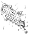
- Fig. 1
- is a rear perspective view of a belt pickup in accordance with the present invention.
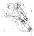
- Fig. 2
- is a fragmentary rear perspective view of the belt pickup of
Figure 1 . - Fig. 3
- is a side view of the fragmentary view of
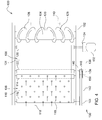
Figure 2 . - Fig. 4
- is a schematic top view of the belt pickup of
Figures 1-3 . - Referring to the Figures, a
belt pickup 100 comprises aframe 102 on which are supported anauger conveyor 104, apickup conveyor 106, and atransfer conveyor 108 and adrive system 130. - The
pickup conveyor 106 comprises a drive roller 112, anidler roller 114, and anendless conveyor belt 116 to which a plurality offingers 118 are attached. Theendless conveyor belt 116 is supported on the drive roller 112 and theidler roller 114 for recirculating movement. As theendless conveyor belt 116 circulates about the rollers, the plurality offingers 118 engage the cut crop material laying on the ground, pick it up, and deposit it on the upwardly facing surface of theendless conveyor belt 116. Theendless conveyor belt 116 carries the cut crop material rearward. Theendless conveyor belt 116 is made of elastomer impregnated fabric. - The
transfer conveyor 108 comprises adrive roller 120, andidler roller 122, and anendless conveyor belt 124. Theendless conveyor belt 124 is supported on thedrive roller 120 and theidler roller 122 for recirculating movement. As theendless conveyor belt 124 circulates about the rollers, theendless conveyor belt 124 receives the cut crop material from theendless conveyor belt 116 of thepickup conveyor 106. Theendless conveyor belt 124 carries the cut crop material rearward. Theendless conveyor belt 124 is made of elastomer impregnated fabric. - The
auger conveyor 104 comprises an elongatecylindrical drum 126 supported on theframe 102. The elongatecylindrical drum 126 hasspiral flights 128 affixed to each end of thecylindrical drum 126. Thespiral flights 128 draw cut crop material inward to a central region of theframe 102 when the auger conveyor is driven in a direction for harvesting crop. - As the
auger conveyor 104 rotates, it receives the cut crop material from theendless conveyor belt 124 of thetransfer conveyor 108, draws it inward from both sides of theendless conveyor belt 124 to a central region of the elongatecylindrical drum 126, and conveys the cut crop material rearward through acentral aperture 110 in theframe 102. Thecentral aperture 110 is provided in the rear of theframe 102 to communicate cut crop through theframe 102 and into the feeder house (not shown) of the agricultural combine (not shown) which supports thebelt pickup 100. - The
pickup conveyor 106 and thetransfer conveyor 108 are coupled to and driven by thedrive system 130. Thedrive system 130 comprises amotor 132 coupled to thedrive roller 120 to drive thedrive roller 120 in rotation, apulley 134 coupled to themotor 132 to be driven in rotation by themotor 132, anendless drive belt 136 coupled to thepulley 134 to be driven by thepulley 134, apulley 138 driven in rotation by theendless drive belt 136, apulley 140 fixed to thepulley 138 to be driven in rotation by thepulley 138, anendless drive belt 142 driven by thepulley 140, and apulley 144 fixed to the drive roller 112 to drive the drive roller 112 in rotation. - In this manner, the
motor 132 drives thedrive roller 120 directly, and drives the drive roller 112 through a series of endless drive belts and pulleys. - A
mechanism 146 is provided to support thepulley 138 and thepulley 140, and to tension theendless drive belt 136 and theendless drive belt 142 by deflecting thepulley 138 and thepulley 140 upward. The tension in theendless drive belt 136 and theendless drive belt 142 increases the friction between the endless drive belts and the pulleys on which they are supported, and therefore permits power to be communicated from themotor 132 to thepulley 144, and thence to the drive roller 112. - The
mechanism 146 comprises a firstmechanical link 148. The firstmechanical link 148 supports ashaft 150 on which thepulley 138 and thepulley 140 are fixed. - The lower end of the first
mechanical link 148 has a hole through which theshaft 150 extends. Theshaft 150 is free to rotate in the hole. Thepulley 138 is fixed on one end of theshaft 150 and thepulley 140 is fixed on the other end of theshaft 150. Thepulley 138 and thepulley 140 are fixed to theshaft 150, and thus rotate together. They are free to rotate with respect to the firstmechanical link 148. - The upper end of the first
mechanical link 148 is pivotally coupled to a first end of a secondmechanical link 152. The firstmechanical link 148 is free to pivot with respect to the secondmechanical link 152. A second end of the secondmechanical link 152 is coupled to theframe 102 of thebelt pickup 100 at apivot joint 154. The secondmechanical link 152 is free to pivot with respect to theframe 102 about thepivot joint 154. - The first
mechanical link 148 and the secondmechanical link 152 generally extend at a right angle with respect to each other. Thus, as the secondmechanical link 152 pivots about thepivot joint 154, the firstmechanical link 148 translates vertically. - A
spring 156 is coupled to theframe 102 of thebelt pickup 100 at a first end of thespring 156. A second end of thespring 156 is coupled to the secondmechanical link 152 at a point between the first end and the second end of the second mechanical link. Thespring 156 applies an upward force to the secondmechanical link 152. This upward force is communicated to the upper end of the firstmechanical link 148. The upward force is communicated through the firstmechanical link 148, theshaft 150, and thepulley 138 and thepulley 140. - The upward force lifts the
pulley 138 and thepulley 140 until it is resisted by a counteracting tension in theendless drive belt 136 and theendless drive belt 142. The counteracting tension in theendless drive belt 136 and theendless drive belt 142 is applied, in turn, topulley 134 andpulley 144. - The claims define the invention, which is not limited to the specific embodiment or embodiments described herein. Obvious variations of the specific embodiments shown herein will be apparent to one skilled in the art.
Claims (8)
- A belt pickup (100) with drive system (130) comprising:a frame (102);a pickup conveyor (106) supported on the frame (102), the pickup conveyor (106) comprising a first endless conveyor belt (116) the first endless conveyor belt (116) having a plurality of fingers (118) fixed to the first endless conveyor belt (116) and extending outward from the first endless conveyor belt (116), wherein the plurality of fingers (118) are disposed to lift cut crop material onto an upper surface of the first endless conveyor belt (116) as the belt pickup (100) travels through the field harvesting crop, and wherein the pickup conveyor (106) further comprises a first drive roller (112) and a first idler roller (114) that support the first endless conveyor belt (116) for recirculating movement about the first drive roller (112) and the first idler roller (114);a transfer conveyor (108) supported on the frame (102), wherein the transfer conveyor (108) is disposed behind the pickup conveyor (106) to receive cut crop material therefrom, and wherein the transfer conveyor (108) further comprises a second endless conveyor belt (124) supported for recirculating movement about a second drive roller (120) and a second idler roller (122); andthe drive system (130) comprising a motor (132) coupled to the second drive roller (120) to drive the second drive roller (120), a first pulley (134) coupled to the motor (132) and driven by the motor (132), a first endless drive belt (136) coupled to the first pulley (134) and driven by the first pulley (134), a second pulley (138) coupled to and driven in rotation by the first endless drive belt (136), a third pulley (140) fixed to the second pulley (138) and driven in rotation by the second pulley (138), a second endless drive belt (142) coupled to and driven by the third pulley (140), and a fourth pulley (144) fixed to the first drive roller (112) to drive the drive roller (112) in rotation.
- The belt pickup (100) with drive system (130) of Claim 1, further comprising a first mechanical link (148) disposed to support the second pulley (138) and the third pulley (140) for free rotation.
- The belt pickup (100) with drive system (130) of Claim 2, further comprising a second mechanical link (152) pivotally coupled to the first mechanical link (148) to support the first mechanical link and to permit the first mechanical link (148) to pivot with respect to the second mechanical link (152)
- The belt pickup (100) with drive system (130) of Claim 3, wherein the second mechanical link (152) is pivotally coupled to the frame (102) at a pivot joint (154) to permit the second mechanical link (152) to pivot with respect to the frame (102).
- The belt pickup (100) with drive system (130) of Claim 4, further comprising a spring (156) that is coupled to the frame (102) and is coupled to the second mechanical link (152) to apply a spring force to the second mechanical link and tension the first endless drive belt (136) and the second endless drive belt (142).
- The belt pickup (100) with drive system (130) of Claim 2, wherein the second pulley (138) and the third pulley (140) are fixed to a shaft (150) that extends through a hole formed in a lower end of the first mechanical link (148).
- The belt pickup (100) with drive system (130) of Claim 6, wherein the shaft (150) is supported for free rotation in the hole.
- The belt pickup (100) with drive system (130) of Claim 3, wherein the first mechanical link (148) and the second mechanical link (152) are generally disposed at a right angle with respect to each other.
Applications Claiming Priority (1)
| Application Number | Priority Date | Filing Date | Title |
|---|---|---|---|
| US14/878,123 US9554515B1 (en) | 2015-10-08 | 2015-10-08 | Belt pickup with drive system |
Publications (2)
| Publication Number | Publication Date |
|---|---|
| EP3153008A1 true EP3153008A1 (en) | 2017-04-12 |
| EP3153008B1 EP3153008B1 (en) | 2018-09-26 |
Family
ID=56896445
Family Applications (1)
| Application Number | Title | Priority Date | Filing Date |
|---|---|---|---|
| EP16188287.3A Active EP3153008B1 (en) | 2015-10-08 | 2016-09-12 | A belt pickup with drive system |
Country Status (4)
| Country | Link |
|---|---|
| US (1) | US9554515B1 (en) |
| EP (1) | EP3153008B1 (en) |
| CN (1) | CN106954433B (en) |
| RU (1) | RU2719187C2 (en) |
Families Citing this family (2)
| Publication number | Priority date | Publication date | Assignee | Title |
|---|---|---|---|---|
| US10543989B2 (en) | 2017-07-06 | 2020-01-28 | KSi Conveyor, Inc. | Belt conveyor with automated in-line tension control system |
| US12495741B2 (en) * | 2021-10-28 | 2025-12-16 | Deere & Company | Harvesting machine belt pickup header with movable pickup belt assembly |
Citations (2)
| Publication number | Priority date | Publication date | Assignee | Title |
|---|---|---|---|---|
| DE202006009408U1 (en) * | 2005-06-30 | 2006-09-14 | Deere & Company, Moline | Harvest header with spring-suspended pickup conveyor belt |
| US20110232249A1 (en) * | 2010-03-29 | 2011-09-29 | Mcilwain Irwin D | Flexible motor support system for a crop gathering device having a harvesting header |
Family Cites Families (10)
| Publication number | Priority date | Publication date | Assignee | Title |
|---|---|---|---|---|
| SU1121799A1 (en) * | 1983-06-20 | 1985-05-30 | Головное специализированное конструкторское бюро по комплексам зерноуборочных машин | Conveyer pickup to agricultural harvesting machine |
| US5255501A (en) * | 1992-02-28 | 1993-10-26 | Mcwilliams Alexander | Baler for forming cylindrical bales |
| RU2096942C1 (en) * | 1995-08-22 | 1997-11-27 | Краснодарский научно-исследовательский институт сельского хозяйства им.П.П.Лукьяненко | Method and apparatus for direct combining pea harvesting |
| RU2262831C1 (en) * | 2004-03-24 | 2005-10-27 | Кубанский государственный аграрный университет | Method for pea harvesting by direct combining process and apparatus for effectuating the same |
| DE102004029953A1 (en) * | 2004-06-21 | 2006-01-12 | Deere & Company, Moline | Header drive |
| US7866136B1 (en) * | 2009-09-22 | 2011-01-11 | Cnh America Llc | Belt pickup for a draper header |
| US8286412B2 (en) * | 2010-06-29 | 2012-10-16 | Macdon Industries Ltd | Crop pick-up assembly |
| CN202746516U (en) * | 2012-06-26 | 2013-02-20 | 潍坊润达机械有限公司 | Belt tension adjusting device |
| CN203537908U (en) * | 2013-11-22 | 2014-04-16 | 王军财 | Feeding and stem discharging assembly of corn thresher |
| CN104206124B (en) * | 2014-08-15 | 2015-12-02 | 安徽理工大学 | A kind of from collecting the removable stalk recycling machine of formula |
-
2015
- 2015-10-08 US US14/878,123 patent/US9554515B1/en active Active
-
2016
- 2016-09-07 RU RU2016136084A patent/RU2719187C2/en active
- 2016-09-12 EP EP16188287.3A patent/EP3153008B1/en active Active
- 2016-09-13 CN CN201610821950.XA patent/CN106954433B/en active Active
Patent Citations (2)
| Publication number | Priority date | Publication date | Assignee | Title |
|---|---|---|---|---|
| DE202006009408U1 (en) * | 2005-06-30 | 2006-09-14 | Deere & Company, Moline | Harvest header with spring-suspended pickup conveyor belt |
| US20110232249A1 (en) * | 2010-03-29 | 2011-09-29 | Mcilwain Irwin D | Flexible motor support system for a crop gathering device having a harvesting header |
Also Published As
| Publication number | Publication date |
|---|---|
| US9554515B1 (en) | 2017-01-31 |
| EP3153008B1 (en) | 2018-09-26 |
| CN106954433B (en) | 2021-03-16 |
| RU2016136084A3 (en) | 2020-02-13 |
| RU2016136084A (en) | 2018-03-13 |
| RU2719187C2 (en) | 2020-04-17 |
| CN106954433A (en) | 2017-07-18 |
Similar Documents
| Publication | Publication Date | Title |
|---|---|---|
| US9386749B1 (en) | Product to windrows pickup head | |
| US3584444A (en) | Stalk pickup apparatus for harvesters | |
| US12052951B2 (en) | Remotely adjustable row divider for an agricultural harvester | |
| US20130313077A1 (en) | Combine crop conveying and feeding system | |
| EP1769669B1 (en) | Conveyor feeder house chain slat | |
| US9781879B2 (en) | Timing apparatus for separately driven sickle knives | |
| US2893537A (en) | Crop pickup mechanism | |
| US9516816B2 (en) | Multiple drums conveyor for an agricultural platform | |
| AU2014280963A1 (en) | Draper roller with active retracting cleat crop stripper | |
| US10925215B2 (en) | Slat-bar cross-members in a feederhouse crop-conveying system | |
| US5913803A (en) | Row crop header with multiple row conveying system | |
| EP3153008B1 (en) | A belt pickup with drive system | |
| US20120055134A1 (en) | Gathering Auger with Independent Speed | |
| EP3466242B1 (en) | Agricultural harvesting head with nested draper belt drive | |
| US20080058041A1 (en) | Guide and Agricultural Machine Incorporating Same | |
| JP2009142214A (en) | Combine harvester | |
| US20120042625A1 (en) | Cantilevered Gathering Auger For Corn Header | |
| KR200200092Y1 (en) | The crops gathering machine | |
| JP2009125022A (en) | Crop harvester | |
| US2979877A (en) | Corn harvester and thershing unit therefor | |
| US1769031A (en) | Harvester thrasher | |
| RU2298312C1 (en) | Cereal crop windrow pickup | |
| KR0131851Y1 (en) | Agricultural products gathering machine | |
| JP2007089462A (en) | Combine harvester | |
| JP4524620B2 (en) | Combine |
Legal Events
| Date | Code | Title | Description |
|---|---|---|---|
| PUAI | Public reference made under article 153(3) epc to a published international application that has entered the european phase |
Free format text: ORIGINAL CODE: 0009012 |
|
| STAA | Information on the status of an ep patent application or granted ep patent |
Free format text: STATUS: THE APPLICATION HAS BEEN PUBLISHED |
|
| AK | Designated contracting states |
Kind code of ref document: A1 Designated state(s): AL AT BE BG CH CY CZ DE DK EE ES FI FR GB GR HR HU IE IS IT LI LT LU LV MC MK MT NL NO PL PT RO RS SE SI SK SM TR |
|
| AX | Request for extension of the european patent |
Extension state: BA ME |
|
| STAA | Information on the status of an ep patent application or granted ep patent |
Free format text: STATUS: REQUEST FOR EXAMINATION WAS MADE |
|
| 17P | Request for examination filed |
Effective date: 20171012 |
|
| RBV | Designated contracting states (corrected) |
Designated state(s): AL AT BE BG CH CY CZ DE DK EE ES FI FR GB GR HR HU IE IS IT LI LT LU LV MC MK MT NL NO PL PT RO RS SE SI SK SM TR |
|
| GRAP | Despatch of communication of intention to grant a patent |
Free format text: ORIGINAL CODE: EPIDOSNIGR1 |
|
| STAA | Information on the status of an ep patent application or granted ep patent |
Free format text: STATUS: GRANT OF PATENT IS INTENDED |
|
| INTG | Intention to grant announced |
Effective date: 20180430 |
|
| GRAS | Grant fee paid |
Free format text: ORIGINAL CODE: EPIDOSNIGR3 |
|
| GRAA | (expected) grant |
Free format text: ORIGINAL CODE: 0009210 |
|
| STAA | Information on the status of an ep patent application or granted ep patent |
Free format text: STATUS: THE PATENT HAS BEEN GRANTED |
|
| AK | Designated contracting states |
Kind code of ref document: B1 Designated state(s): AL AT BE BG CH CY CZ DE DK EE ES FI FR GB GR HR HU IE IS IT LI LT LU LV MC MK MT NL NO PL PT RO RS SE SI SK SM TR |
|
| REG | Reference to a national code |
Ref country code: GB Ref legal event code: FG4D |
|
| REG | Reference to a national code |
Ref country code: CH Ref legal event code: EP |
|
| REG | Reference to a national code |
Ref country code: AT Ref legal event code: REF Ref document number: 1044906 Country of ref document: AT Kind code of ref document: T Effective date: 20181015 |
|
| REG | Reference to a national code |
Ref country code: IE Ref legal event code: FG4D |
|
| REG | Reference to a national code |
Ref country code: DE Ref legal event code: R096 Ref document number: 602016005967 Country of ref document: DE |
|
| REG | Reference to a national code |
Ref country code: NL Ref legal event code: MP Effective date: 20180926 |
|
| PG25 | Lapsed in a contracting state [announced via postgrant information from national office to epo] |
Ref country code: NO Free format text: LAPSE BECAUSE OF FAILURE TO SUBMIT A TRANSLATION OF THE DESCRIPTION OR TO PAY THE FEE WITHIN THE PRESCRIBED TIME-LIMIT Effective date: 20181226 Ref country code: GR Free format text: LAPSE BECAUSE OF FAILURE TO SUBMIT A TRANSLATION OF THE DESCRIPTION OR TO PAY THE FEE WITHIN THE PRESCRIBED TIME-LIMIT Effective date: 20181227 Ref country code: LT Free format text: LAPSE BECAUSE OF FAILURE TO SUBMIT A TRANSLATION OF THE DESCRIPTION OR TO PAY THE FEE WITHIN THE PRESCRIBED TIME-LIMIT Effective date: 20180926 Ref country code: RS Free format text: LAPSE BECAUSE OF FAILURE TO SUBMIT A TRANSLATION OF THE DESCRIPTION OR TO PAY THE FEE WITHIN THE PRESCRIBED TIME-LIMIT Effective date: 20180926 Ref country code: BG Free format text: LAPSE BECAUSE OF FAILURE TO SUBMIT A TRANSLATION OF THE DESCRIPTION OR TO PAY THE FEE WITHIN THE PRESCRIBED TIME-LIMIT Effective date: 20181226 Ref country code: FI Free format text: LAPSE BECAUSE OF FAILURE TO SUBMIT A TRANSLATION OF THE DESCRIPTION OR TO PAY THE FEE WITHIN THE PRESCRIBED TIME-LIMIT Effective date: 20180926 |
|
| REG | Reference to a national code |
Ref country code: LT Ref legal event code: MG4D |
|
| PG25 | Lapsed in a contracting state [announced via postgrant information from national office to epo] |
Ref country code: AL Free format text: LAPSE BECAUSE OF FAILURE TO SUBMIT A TRANSLATION OF THE DESCRIPTION OR TO PAY THE FEE WITHIN THE PRESCRIBED TIME-LIMIT Effective date: 20180926 Ref country code: HR Free format text: LAPSE BECAUSE OF FAILURE TO SUBMIT A TRANSLATION OF THE DESCRIPTION OR TO PAY THE FEE WITHIN THE PRESCRIBED TIME-LIMIT Effective date: 20180926 Ref country code: LV Free format text: LAPSE BECAUSE OF FAILURE TO SUBMIT A TRANSLATION OF THE DESCRIPTION OR TO PAY THE FEE WITHIN THE PRESCRIBED TIME-LIMIT Effective date: 20180926 |
|
| REG | Reference to a national code |
Ref country code: AT Ref legal event code: MK05 Ref document number: 1044906 Country of ref document: AT Kind code of ref document: T Effective date: 20180926 |
|
| PG25 | Lapsed in a contracting state [announced via postgrant information from national office to epo] |
Ref country code: AT Free format text: LAPSE BECAUSE OF FAILURE TO SUBMIT A TRANSLATION OF THE DESCRIPTION OR TO PAY THE FEE WITHIN THE PRESCRIBED TIME-LIMIT Effective date: 20180926 Ref country code: IS Free format text: LAPSE BECAUSE OF FAILURE TO SUBMIT A TRANSLATION OF THE DESCRIPTION OR TO PAY THE FEE WITHIN THE PRESCRIBED TIME-LIMIT Effective date: 20190126 Ref country code: NL Free format text: LAPSE BECAUSE OF FAILURE TO SUBMIT A TRANSLATION OF THE DESCRIPTION OR TO PAY THE FEE WITHIN THE PRESCRIBED TIME-LIMIT Effective date: 20180926 Ref country code: ES Free format text: LAPSE BECAUSE OF FAILURE TO SUBMIT A TRANSLATION OF THE DESCRIPTION OR TO PAY THE FEE WITHIN THE PRESCRIBED TIME-LIMIT Effective date: 20180926 Ref country code: PL Free format text: LAPSE BECAUSE OF FAILURE TO SUBMIT A TRANSLATION OF THE DESCRIPTION OR TO PAY THE FEE WITHIN THE PRESCRIBED TIME-LIMIT Effective date: 20180926 Ref country code: CZ Free format text: LAPSE BECAUSE OF FAILURE TO SUBMIT A TRANSLATION OF THE DESCRIPTION OR TO PAY THE FEE WITHIN THE PRESCRIBED TIME-LIMIT Effective date: 20180926 Ref country code: RO Free format text: LAPSE BECAUSE OF FAILURE TO SUBMIT A TRANSLATION OF THE DESCRIPTION OR TO PAY THE FEE WITHIN THE PRESCRIBED TIME-LIMIT Effective date: 20180926 Ref country code: EE Free format text: LAPSE BECAUSE OF FAILURE TO SUBMIT A TRANSLATION OF THE DESCRIPTION OR TO PAY THE FEE WITHIN THE PRESCRIBED TIME-LIMIT Effective date: 20180926 |
|
| PG25 | Lapsed in a contracting state [announced via postgrant information from national office to epo] |
Ref country code: SM Free format text: LAPSE BECAUSE OF FAILURE TO SUBMIT A TRANSLATION OF THE DESCRIPTION OR TO PAY THE FEE WITHIN THE PRESCRIBED TIME-LIMIT Effective date: 20180926 Ref country code: PT Free format text: LAPSE BECAUSE OF FAILURE TO SUBMIT A TRANSLATION OF THE DESCRIPTION OR TO PAY THE FEE WITHIN THE PRESCRIBED TIME-LIMIT Effective date: 20190126 Ref country code: SK Free format text: LAPSE BECAUSE OF FAILURE TO SUBMIT A TRANSLATION OF THE DESCRIPTION OR TO PAY THE FEE WITHIN THE PRESCRIBED TIME-LIMIT Effective date: 20180926 |
|
| REG | Reference to a national code |
Ref country code: DE Ref legal event code: R097 Ref document number: 602016005967 Country of ref document: DE |
|
| PG25 | Lapsed in a contracting state [announced via postgrant information from national office to epo] |
Ref country code: DK Free format text: LAPSE BECAUSE OF FAILURE TO SUBMIT A TRANSLATION OF THE DESCRIPTION OR TO PAY THE FEE WITHIN THE PRESCRIBED TIME-LIMIT Effective date: 20180926 |
|
| PLBE | No opposition filed within time limit |
Free format text: ORIGINAL CODE: 0009261 |
|
| STAA | Information on the status of an ep patent application or granted ep patent |
Free format text: STATUS: NO OPPOSITION FILED WITHIN TIME LIMIT |
|
| 26N | No opposition filed |
Effective date: 20190627 |
|
| PG25 | Lapsed in a contracting state [announced via postgrant information from national office to epo] |
Ref country code: SI Free format text: LAPSE BECAUSE OF FAILURE TO SUBMIT A TRANSLATION OF THE DESCRIPTION OR TO PAY THE FEE WITHIN THE PRESCRIBED TIME-LIMIT Effective date: 20180926 |
|
| PG25 | Lapsed in a contracting state [announced via postgrant information from national office to epo] |
Ref country code: TR Free format text: LAPSE BECAUSE OF FAILURE TO SUBMIT A TRANSLATION OF THE DESCRIPTION OR TO PAY THE FEE WITHIN THE PRESCRIBED TIME-LIMIT Effective date: 20180926 |
|
| PG25 | Lapsed in a contracting state [announced via postgrant information from national office to epo] |
Ref country code: MC Free format text: LAPSE BECAUSE OF FAILURE TO SUBMIT A TRANSLATION OF THE DESCRIPTION OR TO PAY THE FEE WITHIN THE PRESCRIBED TIME-LIMIT Effective date: 20180926 |
|
| REG | Reference to a national code |
Ref country code: CH Ref legal event code: PL |
|
| PG25 | Lapsed in a contracting state [announced via postgrant information from national office to epo] |
Ref country code: IE Free format text: LAPSE BECAUSE OF NON-PAYMENT OF DUE FEES Effective date: 20190912 Ref country code: LI Free format text: LAPSE BECAUSE OF NON-PAYMENT OF DUE FEES Effective date: 20190930 Ref country code: CH Free format text: LAPSE BECAUSE OF NON-PAYMENT OF DUE FEES Effective date: 20190930 Ref country code: LU Free format text: LAPSE BECAUSE OF NON-PAYMENT OF DUE FEES Effective date: 20190912 |
|
| PG25 | Lapsed in a contracting state [announced via postgrant information from national office to epo] |
Ref country code: FR Free format text: LAPSE BECAUSE OF NON-PAYMENT OF DUE FEES Effective date: 20190930 |
|
| GBPC | Gb: european patent ceased through non-payment of renewal fee |
Effective date: 20200912 |
|
| PG25 | Lapsed in a contracting state [announced via postgrant information from national office to epo] |
Ref country code: CY Free format text: LAPSE BECAUSE OF FAILURE TO SUBMIT A TRANSLATION OF THE DESCRIPTION OR TO PAY THE FEE WITHIN THE PRESCRIBED TIME-LIMIT Effective date: 20180926 |
|
| PG25 | Lapsed in a contracting state [announced via postgrant information from national office to epo] |
Ref country code: SE Free format text: LAPSE BECAUSE OF NON-PAYMENT OF DUE FEES Effective date: 20180926 |
|
| PG25 | Lapsed in a contracting state [announced via postgrant information from national office to epo] |
Ref country code: HU Free format text: LAPSE BECAUSE OF FAILURE TO SUBMIT A TRANSLATION OF THE DESCRIPTION OR TO PAY THE FEE WITHIN THE PRESCRIBED TIME-LIMIT; INVALID AB INITIO Effective date: 20160912 Ref country code: MT Free format text: LAPSE BECAUSE OF FAILURE TO SUBMIT A TRANSLATION OF THE DESCRIPTION OR TO PAY THE FEE WITHIN THE PRESCRIBED TIME-LIMIT Effective date: 20180926 |
|
| PG25 | Lapsed in a contracting state [announced via postgrant information from national office to epo] |
Ref country code: GB Free format text: LAPSE BECAUSE OF NON-PAYMENT OF DUE FEES Effective date: 20200912 |
|
| PG25 | Lapsed in a contracting state [announced via postgrant information from national office to epo] |
Ref country code: MK Free format text: LAPSE BECAUSE OF FAILURE TO SUBMIT A TRANSLATION OF THE DESCRIPTION OR TO PAY THE FEE WITHIN THE PRESCRIBED TIME-LIMIT Effective date: 20180926 |
|
| PGFP | Annual fee paid to national office [announced via postgrant information from national office to epo] |
Ref country code: IT Payment date: 20220926 Year of fee payment: 7 |
|
| PGFP | Annual fee paid to national office [announced via postgrant information from national office to epo] |
Ref country code: BE Payment date: 20240927 Year of fee payment: 9 |
|
| PG25 | Lapsed in a contracting state [announced via postgrant information from national office to epo] |
Ref country code: IT Free format text: LAPSE BECAUSE OF NON-PAYMENT OF DUE FEES Effective date: 20230912 |
|
| PG25 | Lapsed in a contracting state [announced via postgrant information from national office to epo] |
Ref country code: IT Free format text: LAPSE BECAUSE OF NON-PAYMENT OF DUE FEES Effective date: 20230912 |
|
| PGFP | Annual fee paid to national office [announced via postgrant information from national office to epo] |
Ref country code: DE Payment date: 20250820 Year of fee payment: 10 |