EP3152169B1 - Process and apparatus for refining molten glass - Google Patents
Process and apparatus for refining molten glass Download PDFInfo
- Publication number
- EP3152169B1 EP3152169B1 EP15728984.4A EP15728984A EP3152169B1 EP 3152169 B1 EP3152169 B1 EP 3152169B1 EP 15728984 A EP15728984 A EP 15728984A EP 3152169 B1 EP3152169 B1 EP 3152169B1
- Authority
- EP
- European Patent Office
- Prior art keywords
- housing
- molten glass
- guide
- longitudinal axis
- guides
- Prior art date
- Legal status (The legal status is an assumption and is not a legal conclusion. Google has not performed a legal analysis and makes no representation as to the accuracy of the status listed.)
- Active
Links
Images


Classifications
-
- C—CHEMISTRY; METALLURGY
- C03—GLASS; MINERAL OR SLAG WOOL
- C03B—MANUFACTURE, SHAPING, OR SUPPLEMENTARY PROCESSES
- C03B5/00—Melting in furnaces; Furnaces so far as specially adapted for glass manufacture
- C03B5/16—Special features of the melting process; Auxiliary means specially adapted for glass-melting furnaces
- C03B5/225—Refining
- C03B5/2257—Refining by thin-layer fining
-
- C—CHEMISTRY; METALLURGY
- C03—GLASS; MINERAL OR SLAG WOOL
- C03B—MANUFACTURE, SHAPING, OR SUPPLEMENTARY PROCESSES
- C03B5/00—Melting in furnaces; Furnaces so far as specially adapted for glass manufacture
- C03B5/16—Special features of the melting process; Auxiliary means specially adapted for glass-melting furnaces
- C03B5/225—Refining
- C03B5/2252—Refining under reduced pressure, e.g. with vacuum refiners
-
- C—CHEMISTRY; METALLURGY
- C03—GLASS; MINERAL OR SLAG WOOL
- C03B—MANUFACTURE, SHAPING, OR SUPPLEMENTARY PROCESSES
- C03B5/00—Melting in furnaces; Furnaces so far as specially adapted for glass manufacture
- C03B5/16—Special features of the melting process; Auxiliary means specially adapted for glass-melting furnaces
- C03B5/235—Heating the glass
- C03B5/2356—Submerged heating, e.g. by using heat pipes, hot gas or submerged combustion burners
Definitions
- the present disclosure is directed to a process according to claim 13 and an apparatus according to claim 1 for refining glass.
- Silica-based glass such as soda-lime-silica glass
- Molten glass used to make such articles is conventionally prepared by melting various glass-forming materials in a furnace or tank at elevated temperature. During this process, gases (e.g., SO 2 , CO 2 , H 2 O, etc.) are produced, which may evolve to form gas bubbles or "seeds" within the molten glass.
- gases e.g., SO 2 , CO 2 , H 2 O, etc.
- the process of removing gas bubbles and/or dissolved gases from molten glass is referred to as "refining" or "degassing.”
- US 2,936,549 discloses a glass making apparatus including a melting tank, a working or receiving tank spaced apart from the melting tank, and a means for conveying the molten glass in the form of a film of molten glass from one tank to another tank so that gas may easily escape from the molten glass during its movement between the tanks.
- US 3,320,045 discloses a furnace for the manufacture of fused quartz that includes a pretreatment furnace in communication with a melting furnace in which a melt of quartz crystals is contained.
- the quartz raw material used to form the melt is heated in the pretreatment furnace at a temperature lower than the melting temperature of the raw material to remove dissolved gasses therefrom. Thereafter, the degassed quartz is introduced into the melting furnace and distributed over a surface of the melt.
- US 2009/0249834 discloses a method of removing gaseous inclusions from a viscous liquid, wherein the viscous liquid is passed through a layer of filter particles such that the gaseous inclusions combine or coalesce within the layer of filter particles and form larger gaseous inclusions which rise to a top surface of the viscous liquid and escape therefrom.
- a general object of the disclosure in accordance with one aspect of the disclosure, is to provide an apparatus for refining molten glass that promotes the rapid release of gas bubbles therefrom and thereby reduces the time needed to refine the molten glass, or the "refining time.”
- the present disclosure embodies a number of aspects that can be implemented separately from or in combination with each other.
- An apparatus for refining molten glass in accordance with one aspect of the disclosure, includes: a housing and a guide positioned within the housing.
- the housing has a vertically oriented longitudinal axis, a transverse axis perpendicular to the longitudinal axis, an inlet at an upper end to receive molten glass, and an outlet a lower end to discharge molten glass therefrom.
- the guide has a flow surface upon which molten glass can flow between the inlet and the outlet of the housing.
- the flow surface of the guide has a surface area that is greater than a transverse cross-sectional area of the housing, and, when a volume of molten glass is introduced into the housing, the volume of molten glass is distributed over the flow surface of the guide such that the surface area of the volume of molten glass is increased and the thickness of the volume molten glass is decreased.
- an apparatus for refining molten glass that includes: a housing having a vertically oriented longitudinal axis and a transverse axis perpendicular to the longitudinal axis, an inlet at an upper end of the housing to receive molten glass, an outlet at a lower end of the housing to discharge molten glass from the housing, and a guide extending at least partway across the housing.
- the guide directs molten glass in a generally downward direction through the housing and in a parallel or oblique direction relative to the transverse axis of the housing such that molten glass flowing from the upper end to the lower end of the housing moves relative to the longitudinal axis of the housing.
- the molten glass is directed through the housing such that the molten glass repeatedly intersects the longitudinal axis of the housing.
- the molten glass is directed by the guide such that the molten glass repeatedly passes from one side of the longitudinal axis of the housing to another, without physically intersecting the longitudinal axis.
- the molten glass may be directed such that the molten glass repeatedly revolves around the longitudinal axis of the housing.
- the guide may include a series of guides that direct the molten glass through the housing such that the molten glass cascades over the guides in succession.
- FIG. 1 illustrates an apparatus 10, in accordance with one embodiment of the present disclosure, for refining molten glass.
- the apparatus 10 includes a housing 12 that defines an inner chamber 14 and has a vertically oriented longitudinal axis L and a transverse axis T perpendicular to the longitudinal axis L. Unrefined molten glass is received at an upper end of the housing 12 and refined molten glass is discharged from a lower end of the housing 12.
- the housing 12 includes an inlet 16 through which a stream of unrefined molten glass may be received, an outlet 18 through which a stream of refined molten glass may be discharged, and a sidewall 20 that extends between the inlet 16 and the outlet 18 of the housing 12.
- FIG. 1 illustrates an apparatus 10, in accordance with one embodiment of the present disclosure, for refining molten glass.
- the apparatus 10 includes a housing 12 that defines an inner chamber 14 and has a vertically oriented longitudinal axis L and a transverse axis T perpendic
- the sidewall 20 of the housing 12 is cylindrical and the housing 12 has a transverse cross section that is circular in shape.
- the transverse cross section of the housing 12 may take on different shapes.
- the housing 12 may have an elliptical or polygonal transverse cross-sectional shape.
- the housing 12 may have a longitudinal length measured along the longitudinal axis L thereof and a width measured along the transverse axis T.
- the length of the housing 12 may be substantially the same as the width of the housing 12, or the housing 12 may have a length greater than its width.
- the length of the housing 12 may be in the range of 1-5 meters and the width of the housing 12 may be in the range of 1-5 meters.
- the residence time of a volume of molten glass flowing through a housing 12 having such dimensions may be in the range of 1-12 hours, and such housing 12 may produce about 50 tons to about 300 tons of refined molten glass per day.
- Molten glass is received at the inlet 16 of the housing 12 and is flowed over one or more guides 22 having flow surfaces 24 upon which molten glass can flow between the upper end and the lower end of the housing 12.
- the guides 22 direct the molten glass in a generally downward direction through the housing 12, while also directing the molten glass in a parallel or oblique direction relative to the transverse axis T of the housing 12.
- the molten glass is directed by the guides 22 such that the molten glass moves relative to the longitudinal axis L of the housing 12.
- the molten glass may repeatedly traverse, pass, and/or move over, along, through, around, about, across, or back and forth with respect to the longitudinal axis L of the housing 12 as the molten glass flows from the inlet 16 to the outlet 18 of the housing 12.
- this may mean that the molten glass intersects the longitudinal axis L of the housing 12 as it flows through the housing 12.
- the molten glass passes from one side of the longitudinal axis L to another without physically intersecting the longitudinal axis L.
- the molten glass may move back and forth within the housing 12 as it flows over the guides 22, or the molten glass may revolve around the longitudinal axis L of the housing 12 as it flows from the inlet 16 to the outlet 18 of the housing 12.
- the guides 22 may take on a variety of different shapes, including, for example, plates, trays, steps, shelves, baffles, and/or rods, to name a few.
- a volume of molten glass When a volume of molten glass is introduced into the housing 12, the volume of molten glass is distributed over the flow surfaces 24 of the guides 22 such that the surface area of the volume of molten glass is increased and the thickness of the volume of molten glass is decreased.
- a volume of molten glass received at the inlet 16 of the housing 12 may have a surface area in the range of 0.01 square meters to five square meters and a thickness in the range of 0.5 cm to 100 cm.
- the volume of molten glass may have a surface area in the range of 0.5 square meters to 20 square meters and a thickness in the range of 0.5 cm to 35 cm, which represents 1 to 2000-fold increase in surface area and 1 to 100-fold decrease in thickness.
- the "thickness" of the molten glass refers to the height or level of the molten glass above the one or more flow surfaces 24 of the one or more guides 22. Reducing the thickness of the volume of molten glass allows gas bubbles that are dissolved or trapped within the molten glass to rise to a free surface thereof and escape from the molten glass in a relatively short amount of time.
- the rate at which molten glass is flowed through the housing 12 is controlled such that the chamber 14 is never completely filled or flooded with molten glass. More specifically, the rate at which molten glass is flowed through the housing 12 is controlled such that the molten glass flowing over the flow surfaces 24 of the guides 22 has a free surface.
- the overall flow surface area of the guides 22 is relatively large in comparison to the transverse cross-sectional area of the housing 12, which allows molten glass flowing through the housing 12 to be distributed over a relatively large surface area in a space having a relatively small volume.
- the housing 12 may have a transverse cross-sectional area of between 0.5 m 2 and 20 m 2
- the overall flow surface area of the guides 22 may be between 50 m 2 and 500 m 2 .
- the apparatus 10 illustrated in FIG. 1 includes a series of guides 22 that are spaced apart from one another along the longitudinal axis L of the housing 12.
- the guides 22 extend partway across the housing 12. That is, the guides 22 extend from one side of the housing 12 across the longitudinal axis L of the housing 12, but the guides 22 do not extend entirely across the housing 12.
- the guides 22 illustrated in FIG. 1 extend in a downward direction at an oblique angle relative to the transverse axis T of the housing 12. However, in other embodiments, some or all of the guides 22 may extend in a substantially parallel direction to the transverse axis T of the housing 12.
- the guides 22 may extend at a downward angle in the range of zero degrees to 30 degrees from the transverse axis T of the housing 12, and may be spaced apart from one another at distances in the range of 3-25 inches. In some specific embodiments, the guides 22 may extend at a downward angle in the range of 2-3 degrees from the transverse axis T of the chamber 14.
- the guides 22 are alternately arranged on opposite sides of the housing 12, such that the guides 22 overlap one another along the longitudinal axis L of the housing 12.
- the molten glass flows across the guide 22 towards the downstream end 28 of the guide 22, and then drops from a free edge 30 of the guide 22 onto the upstream end 26 of the next lower guide 22.
- the molten glass is repeatedly deflected in opposite transverse directions such that the molten glass cascades from one guide 22 to another and makes a zigzag path through the housing 12.
- a vacuum pump and evacuation system 32 may be in fluid communication with the apparatus 10 for creating a sub-atmospheric pressure environment within the housing 12. Lowering the atmospheric pressure within the housing 12 may help increase the rate at which gas bubbles are removed from the molten glass as it flows over the guides 22 and through the housing 12. In addition, the vacuum pump and evacuation system 32 may help maintain a suitably low-pressure environment within the housing 12 by continuously drawing off gases that are released from the molten glass as it flows through the housing 12.
- a vacuum port 34 may be provided in the housing 12 for removing or evacuating gases therefrom.
- molten glass may be received at the inlet 16 of the housing 12 and may pass through multiple stages or zones as it flows to the outlet 18 of the housing 12, with each zone being characterized by different process variables.
- the temperature and pressure may be intentionally varied at different locations within the housing 12 to create different temperature and pressure zones within the housing 12.
- the declination angles and spacing between the guides 22 may be different in one area of the housing 12 as compared to another, and those different areas may define different zones within the housing 12.
- FIGS. 2-17 illustrate additional embodiments of apparatuses for refining molten glass. These embodiments are similar in many respects to the embodiment illustrated in FIG. 1 , and like numerals among the embodiments generally designate like or corresponding elements throughout the several views of the drawing figures. Accordingly, the descriptions of the embodiments are incorporated into one another, and description of subject matter common to the embodiments generally may not be repeated here.
- some or all of the guides 22 may have extensions 36 located at their downstream ends 28, which may help guide the molten glass from one guide 22 to the next lower guide 22 within the housing 12.
- the extensions 36 may help increase the laminarity of the flow of molten glass, for example, by preventing bubbles from becoming incorporated into the molten glass as it flows from one guide 22 to another.
- the extensions 36 may extend from the downstream ends 28 of the guides 22 in a direction parallel to the longitudinal axis L of the housing 12, or the extensions 36 may be angled slightly inwardly or outwardly from the downstream ends 28 of the guides 22.
- the guides 22 may include barriers 38 along their flow surfaces 24, which may help maintain a generally uniform level of molten glass over the flow surfaces 24 of the guides 22.
- the guides 22 also may include heaters 40 for supplying heat to the molten glass as it flows over the guides.
- the heaters 40 may include any suitable source of heat, and may be embedded in, mounted under, or otherwise carried by the guides 22. In the embodiment illustrated in FIG. 3 , the heaters 40 are positioned below the flow surfaces 24 of the guides 22.
- the heaters 40 may help adjust and/or control the temperature of the molten glass as it flows through the housing 12, for example, so that the molten glass exhibits a suitable temperature for refining.
- the heaters 40 may help control the rate at which the molten glass is cooled as it flows through the housing 12 so that the molten glass exhibits a suitable temperature for use in downstream forming operations by the time it reaches the outlet 18 of the housing 12.
- the apparatus 10 also may include burners 42, which may heat the molten glass as it flows through the housing 12.
- the burners 42 may be positioned at various locations within the housing 12, and may be positioned such that the burners 42 extend from the sidewall 20 of the housing 12 into the chamber 14.
- the heaters 40, the burners 42, or both may be part of a heating system that supplies a controlled amount of heat to the molten glass flowing through the housing 12.
- the apparatus 10 also may include a ventilation system 44 to vent air and/or other gases out of the housing 12.
- the ventilation system 44 may include a conduit 46 with apertures 48 through which air and/or other gases can exit the housing 12.
- the conduit 46 may extend along the sidewall 20 of the housing 12.
- the vacuum pump and evacuation system 32, the ventilation system 44, the heating system, or a combination thereof may be part of an overall management system that controls the temperature and/or pressure at various locations within the housing 12.
- the apparatus 10 also may include one or more vibrators 50 for adding vibration energy, e.g., sonic energy, to the molten glass as it flows over the guides 22.
- vibration energy e.g., sonic energy
- Adding vibration energy to the molten glass may promote cavitations, which may cause gas bubbles that are dissolved or trapped within the molten glass to collide, rupture, and/or coalesce so that the gas bubbles can rise to a free surface of the molten glass and escape therefrom in a relatively short amount of time.
- Adding vibration energy to the molten glass may be accomplished by adding vibration energy to one or more of the guides 22, for example, by coupling the vibrators 50 to the guides 22.
- the vibrators 50 may be carried by the guides 22, mounted on or under the guides 22, and/or embedded in the guides 22.
- the vibrators 50 are positioned along the sidewall 20 of the housing 12 and are coupled to the upstream ends 26 of the guides 22.
- Suitable vibrators 50 for imparting vibration energy to molten glass flowing through the housing 12 may include actuators, sonic wave generators, or sonic horns, also known as acoustic horns.
- vibrators 50' may be coupled to the guides 22 along the longitudinal axis L of the housing 12.
- an input member 52 extends through the housing 12 along the longitudinal axis L of the housing 12.
- the input member 52 may be coupled to the vibrators 50' in a manner that allows the vibrators 50' to be actuated by the input member 52.
- the vibrators 50' may be configured to impart vibration energy to the guides 22 upon receiving vibration energy or a signal from the input member 52.
- the input member 52 may include a tube, or any other suitable device that can be used to actuate the vibrators 50' or otherwise impart vibration energy to the vibrators 50' and/or the guides 22.
- multiple vibrators 50" may be positioned in spaced apart relation to each other along the flow surfaces 24 of the guides 22.
- molten glass may flow across one of the guides 22, from the upstream end 26 to the downstream end 28 thereof, and may drop from the free edge 30 of the guide 22 onto the upstream end 22 of the next lower guide 22.
- the molten glass may flow over the vibrators 50" as it flows across the guide 22.
- the energy intensity and frequency of the vibrators 50" may be adjusted in response to the thickness and/or the viscosity of the molten glass flowing over the guides 22. For example, higher intensity and frequency vibrations may be imparted to the guides 22 if needed to compensate for thicker or more viscous flows of molten glass, and vice versa.
- FIGS. 13 and 14 illustrate an apparatus 110 for refining molten glass, in accordance with another embodiment of the disclosure.
- the apparatus 110 includes a housing 112 defining an inner chamber 114 and guides 122 that fully extend across the housing 112.
- the guides 122 have flow surfaces 124 upon which molten glass can flow.
- the guides 122 may include slots 154 between their upstream and downstream ends 126, 128 so that molten glass can flow from one guide 122 to another via the slots 154.
- the molten glass when molten glass is received at an upstream end 126 of one of the guides 122, the molten glass may flow across the guide 122 towards the downstream end 128 of the guide 122, and then may drop through the slot 154 in the guide 122 onto the upstream end 126 of the next lower guide 122.
- These types of guides 122 may allow foam on the surface of the molten glass to collect at the downstream ends 128 of the guides 122 such that the foam is skimmed off and separated from the molten glass as it flows through the housing 112.
- FIG. 15 illustrates a portion of an apparatus 210 for refining molten glass, in accordance with another embodiment of the disclosure.
- the apparatus 210 includes a housing 212 defining an inner chamber 214 and alternating first and second guides 222A, 222B.
- the first and second guides 222A, 222B have first and second flow surfaces 224A, 224B upon which molten glass can flow.
- the first and second guides 222A, 222B provide different types of passageways through which molten glass can flow.
- the first guide 222A may include a central passageway 256 and the second guide 222B may be defined by one or more peripheral passageways 258.
- molten glass may flow through the central passageway 256 of the first guide 222A, onto the flow surface 224B of the second guide 222B, and then over one or more free edges 230B of the second guide 222B to the next lower guide 222A.
- the first and second guides 222A, 222B may be segmented or unitary structures, which may or may not be attached to the sidewall 220 of the housing 12.
- the first guide 222A may be annular in shape and the second guide 222B may be in the shape of a disc, with the relative dimensions of the first and second guides 222A, 222B being such that the second guide 222B and the central passageway 256 of the first guide 222A are in overlapping relationship when viewed along the longitudinal axis L of the chamber 214.
- FIG. 16 illustrates an apparatus 310 for refining molten glass, in accordance with yet another embodiment of the disclosure.
- the apparatus 310 includes a housing 312 that defines an inner chamber 314 having a vertically oriented longitudinal axis L and a transverse axis T perpendicular to the longitudinal axis L. Unrefined molten glass is received at an upper end of the chamber 314 and refined molten glass is discharged from a lower end of the chamber 314.
- the housing 312 includes an inlet 316 through which a stream of unrefined molten glass may be received, an outlet 318 through which a stream of refined molten glass may be discharged, and a sidewall 320 that extends between the inlet 316 and the outlet 318 of the housing 312.
- molten glass is received at the inlet 316 of the housing 312 and is distributed over a helical guide 322.
- the helical guide 322 provides a flow surface 324 upon which molten glass can flow between the upper end and the lower end of the chamber 314.
- Molten glass is directed through the chamber 314 by the guide 322 such that it flows in a generally downward direction through the chamber 314 and in an oblique direction relative to the transverse axis T of the housing 12. More specifically, molten glass is directed by the helical guide 322 such that it revolves around the longitudinal axis L of the chamber 314 in the form of a spiral.
- the helical guide 322 may be carried by a central shaft 360 that may extend along the longitudinal axis L of the chamber 314.
- the apparatus 310 also may include a vacuum pump and evacuation system 332 with a vacuum port 334 for creating a sub-atmospheric pressure environment within the chamber 314.
- One or more heaters and/or vibrators may be located within the chamber 314 for supplying heat or vibration energy to the molten glass as it flows over the helical guide 322.
- One or more barriers also may be located along the flow surface 324 of the helical guide 322 to help maintain a desired level of molten glass over the helical guide 322 and/or to help direct the flow of molten glass over the guide 322.
- a continuous stream of molten glass is introduced into the apparatus 310 by allowing a controlled amount of molten glass to continuously flow from a body of molten glass held within a glass melting furnace 362 into the chamber 314.
- the body of molten glass may have a free surface located above the upper end of the chamber 314 such that molten glass can flow by gravity from the furnace 362 into the chamber 314.
- a flow control device 364 may be placed in the flow path of the molten glass, upstream of the inlet 316, to regulate the amount of molten glass that enters chamber 314.
- the flow control device 364 also may help dissipate or reduce the amount of foam on the surface of the molten glass that enters the chamber 314.
- FIG. 17 illustrates an apparatus 410 for refining molten glass, in accordance with another embodiment of the disclosure.
- the apparatus 410 includes a housing 412 that defines an inner chamber 414 having a vertically oriented longitudinal axis L and a transverse axis T perpendicular to the longitudinal axis L.
- Unrefined molten glass is received at an upper end of the chamber 414 and is distributed over a successive series of guides 422 that extend radially outwardly from a central shaft 460.
- the flow direction of the molten glass changes as it flows from one guide 422 to another.
- some or all of the guides 422 may be arranged such that molten glass cascades from one guide 422 to another while following a generally straight path through the chamber 414.
- the process and apparatus for refining molten glass disclosed herein may be used to refine various silica-based glass compositions as well as glass precursor compositions, and may be retrofitted or incorporated into various glass manufacturing processes and various glass furnace designs, including, but certainly not limited to, the illustrative glass manufacturing processes and glass furnace designs shown in the drawings and described herein.
- the process and apparatus disclosed herein may be used to refine molten glass that has been melted in a vacuum induction melter, a submerged combustion melter, or any other suitable melting furnace.
Landscapes
- Chemical & Material Sciences (AREA)
- Engineering & Computer Science (AREA)
- Materials Engineering (AREA)
- Organic Chemistry (AREA)
- Combustion & Propulsion (AREA)
- Glass Melting And Manufacturing (AREA)
- Glass Compositions (AREA)
Description
- The present disclosure is directed to a process according to claim 13 and an apparatus according to claim 1 for refining glass.
- Silica-based glass, such as soda-lime-silica glass, is prevalent in the manufacture of glass containers and other articles. Molten glass used to make such articles is conventionally prepared by melting various glass-forming materials in a furnace or tank at elevated temperature. During this process, gases (e.g., SO2, CO2, H2O, etc.) are produced, which may evolve to form gas bubbles or "seeds" within the molten glass. The process of removing gas bubbles and/or dissolved gases from molten glass is referred to as "refining" or "degassing."
-
US 2,936,549 discloses a glass making apparatus including a melting tank, a working or receiving tank spaced apart from the melting tank, and a means for conveying the molten glass in the form of a film of molten glass from one tank to another tank so that gas may easily escape from the molten glass during its movement between the tanks. -
US 3,320,045 discloses a furnace for the manufacture of fused quartz that includes a pretreatment furnace in communication with a melting furnace in which a melt of quartz crystals is contained. The quartz raw material used to form the melt is heated in the pretreatment furnace at a temperature lower than the melting temperature of the raw material to remove dissolved gasses therefrom. Thereafter, the degassed quartz is introduced into the melting furnace and distributed over a surface of the melt. -
US 2009/0249834 discloses a method of removing gaseous inclusions from a viscous liquid, wherein the viscous liquid is passed through a layer of filter particles such that the gaseous inclusions combine or coalesce within the layer of filter particles and form larger gaseous inclusions which rise to a top surface of the viscous liquid and escape therefrom. - A general object of the disclosure, in accordance with one aspect of the disclosure, is to provide an apparatus for refining molten glass that promotes the rapid release of gas bubbles therefrom and thereby reduces the time needed to refine the molten glass, or the "refining time."
- The present disclosure embodies a number of aspects that can be implemented separately from or in combination with each other.
- An apparatus for refining molten glass, in accordance with one aspect of the disclosure, includes: a housing and a guide positioned within the housing. The housing has a vertically oriented longitudinal axis, a transverse axis perpendicular to the longitudinal axis, an inlet at an upper end to receive molten glass, and an outlet a lower end to discharge molten glass therefrom. The guide has a flow surface upon which molten glass can flow between the inlet and the outlet of the housing. The flow surface of the guide has a surface area that is greater than a transverse cross-sectional area of the housing, and, when a volume of molten glass is introduced into the housing, the volume of molten glass is distributed over the flow surface of the guide such that the surface area of the volume of molten glass is increased and the thickness of the volume molten glass is decreased.
- In accordance with another aspect of the disclosure, there is provided an apparatus for refining molten glass that includes: a housing having a vertically oriented longitudinal axis and a transverse axis perpendicular to the longitudinal axis, an inlet at an upper end of the housing to receive molten glass, an outlet at a lower end of the housing to discharge molten glass from the housing, and a guide extending at least partway across the housing. The guide directs molten glass in a generally downward direction through the housing and in a parallel or oblique direction relative to the transverse axis of the housing such that molten glass flowing from the upper end to the lower end of the housing moves relative to the longitudinal axis of the housing. In some embodiments, the molten glass is directed through the housing such that the molten glass repeatedly intersects the longitudinal axis of the housing. According to the invention the molten glass is directed by the guide such that the molten glass repeatedly passes from one side of the longitudinal axis of the housing to another, without physically intersecting the longitudinal axis. For example, the molten glass may be directed such that the molten glass repeatedly revolves around the longitudinal axis of the housing. In another embodiment, the guide may include a series of guides that direct the molten glass through the housing such that the molten glass cascades over the guides in succession.
- In accordance with yet another aspect of the disclosure, there is provided a process for refining molten glass according to claim 13.
- The disclosure, together with additional objects, features, advantages and aspects thereof, will be best understood from the following description, the appended claims and the accompanying drawings, in which:
-
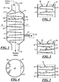
FIG. 1 is a schematic illustration of a side sectional view of an apparatus for refining molten glass, in accordance with one embodiment of the disclosure; -
FIG. 2 is a schematic illustration of a side sectional view of a portion of an apparatus for refining molten glass, in accordance with another embodiment of the disclosure; -
FIG. 3 is a schematic illustration of a side sectional view of a portion of an apparatus for refining molten glass, in accordance with yet another embodiment of the disclosure; -
FIG. 4 is a schematic illustration of a top sectional view of an apparatus for refining molten glass, in accordance with a fourth embodiment of the disclosure; -
FIG. 5 is a side sectional view of a portion of the apparatus illustrated inFIG. 4 ; -
FIG. 6 is a schematic illustration of a top sectional view of an apparatus for refining molten glass, in accordance with a fifth embodiment of the disclosure; -
FIG. 7 is a side sectional view of a portion of the apparatus illustrated inFIG. 6 ; -
FIG. 8 is a schematic illustration of a side sectional view of a portion of an apparatus for refining molten glass, in accordance with a sixth embodiment of the disclosure; -
FIG. 9 is a schematic illustration of a side sectional view of an apparatus for refining molten glass, in accordance with a seventh embodiment of the disclosure; -
FIG. 10 is a schematic illustration of a side sectional view of a portion of an apparatus for refining molten glass, in accordance with an eighth embodiment of the disclosure; -
FIG. 11 is an enlarged top sectional view of the apparatus ofFIG. 10 ; -
FIG. 12 is an enlarged fragmentary view of the apparatus ofFIG. 10 ; -
FIG. 13 is a schematic illustration of a top sectional view of an apparatus for refining molten glass, in accordance with a ninth embodiment of the disclosure; -
FIG. 14 is an enlarged fragmentary view of the apparatus ofFIG. 13 ; -
FIG. 15 is a schematic illustration of a side sectional view of a portion of an apparatus for refining molten glass, in accordance with a tenth embodiment of the disclosure; -
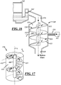
FIG. 16 is a schematic illustration of a side sectional view of an apparatus for refining molten glass, in accordance with an eleventh embodiment of the disclosure; and -
FIG. 17 is a schematic illustration of a perspective view of a portion of an apparatus for refining molten glass, in accordance with a twelfth embodiment of the disclosure. -
FIG. 1 illustrates anapparatus 10, in accordance with one embodiment of the present disclosure, for refining molten glass. Theapparatus 10 includes ahousing 12 that defines aninner chamber 14 and has a vertically oriented longitudinal axis L and a transverse axis T perpendicular to the longitudinal axis L. Unrefined molten glass is received at an upper end of thehousing 12 and refined molten glass is discharged from a lower end of thehousing 12. Thehousing 12 includes aninlet 16 through which a stream of unrefined molten glass may be received, anoutlet 18 through which a stream of refined molten glass may be discharged, and asidewall 20 that extends between theinlet 16 and theoutlet 18 of thehousing 12. In the embodiment illustrated inFIG. 1 , thesidewall 20 of thehousing 12 is cylindrical and thehousing 12 has a transverse cross section that is circular in shape. In other embodiments, however, the transverse cross section of thehousing 12 may take on different shapes. For example, in other embodiments, thehousing 12 may have an elliptical or polygonal transverse cross-sectional shape. - The
housing 12 may have a longitudinal length measured along the longitudinal axis L thereof and a width measured along the transverse axis T. The length of thehousing 12 may be substantially the same as the width of thehousing 12, or thehousing 12 may have a length greater than its width. In some specific embodiments, the length of thehousing 12 may be in the range of 1-5 meters and the width of thehousing 12 may be in the range of 1-5 meters. The residence time of a volume of molten glass flowing through ahousing 12 having such dimensions may be in the range of 1-12 hours, andsuch housing 12 may produce about 50 tons to about 300 tons of refined molten glass per day. - Molten glass is received at the
inlet 16 of thehousing 12 and is flowed over one ormore guides 22 havingflow surfaces 24 upon which molten glass can flow between the upper end and the lower end of thehousing 12. In particular, theguides 22 direct the molten glass in a generally downward direction through thehousing 12, while also directing the molten glass in a parallel or oblique direction relative to the transverse axis T of thehousing 12. Also, the molten glass is directed by theguides 22 such that the molten glass moves relative to the longitudinal axis L of thehousing 12. For example, the molten glass may repeatedly traverse, pass, and/or move over, along, through, around, about, across, or back and forth with respect to the longitudinal axis L of thehousing 12 as the molten glass flows from theinlet 16 to theoutlet 18 of thehousing 12. In some embodiments, this may mean that the molten glass intersects the longitudinal axis L of thehousing 12 as it flows through thehousing 12. According to the invention the molten glass passes from one side of the longitudinal axis L to another without physically intersecting the longitudinal axis L. For example, the molten glass may move back and forth within thehousing 12 as it flows over theguides 22, or the molten glass may revolve around the longitudinal axis L of thehousing 12 as it flows from theinlet 16 to theoutlet 18 of thehousing 12. Theguides 22 may take on a variety of different shapes, including, for example, plates, trays, steps, shelves, baffles, and/or rods, to name a few. - When a volume of molten glass is introduced into the
housing 12, the volume of molten glass is distributed over theflow surfaces 24 of theguides 22 such that the surface area of the volume of molten glass is increased and the thickness of the volume of molten glass is decreased. For example, a volume of molten glass received at theinlet 16 of thehousing 12 may have a surface area in the range of 0.01 square meters to five square meters and a thickness in the range of 0.5 cm to 100 cm. However, after the volume of molten glass has been distributed over theflow surfaces 24 of theguides 22, the volume of molten glass may have a surface area in the range of 0.5 square meters to 20 square meters and a thickness in the range of 0.5 cm to 35 cm, which represents 1 to 2000-fold increase in surface area and 1 to 100-fold decrease in thickness. As used herein, the "thickness" of the molten glass refers to the height or level of the molten glass above the one ormore flow surfaces 24 of the one ormore guides 22. Reducing the thickness of the volume of molten glass allows gas bubbles that are dissolved or trapped within the molten glass to rise to a free surface thereof and escape from the molten glass in a relatively short amount of time. Accordingly, the rate at which molten glass is flowed through thehousing 12 is controlled such that thechamber 14 is never completely filled or flooded with molten glass. More specifically, the rate at which molten glass is flowed through thehousing 12 is controlled such that the molten glass flowing over the flow surfaces 24 of theguides 22 has a free surface. - The overall flow surface area of the
guides 22 is relatively large in comparison to the transverse cross-sectional area of thehousing 12, which allows molten glass flowing through thehousing 12 to be distributed over a relatively large surface area in a space having a relatively small volume. For example, thehousing 12 may have a transverse cross-sectional area of between 0.5 m2 and 20 m2, and the overall flow surface area of theguides 22 may be between 50 m2 and 500 m2. - The
apparatus 10 illustrated inFIG. 1 includes a series ofguides 22 that are spaced apart from one another along the longitudinal axis L of thehousing 12. Theguides 22 extend partway across thehousing 12. That is, theguides 22 extend from one side of thehousing 12 across the longitudinal axis L of thehousing 12, but theguides 22 do not extend entirely across thehousing 12. Theguides 22 illustrated inFIG. 1 extend in a downward direction at an oblique angle relative to the transverse axis T of thehousing 12. However, in other embodiments, some or all of theguides 22 may extend in a substantially parallel direction to the transverse axis T of thehousing 12. In some embodiments, theguides 22 may extend at a downward angle in the range of zero degrees to 30 degrees from the transverse axis T of thehousing 12, and may be spaced apart from one another at distances in the range of 3-25 inches. In some specific embodiments, theguides 22 may extend at a downward angle in the range of 2-3 degrees from the transverse axis T of thechamber 14. - In the embodiment illustrated in
FIG. 1 , theguides 22 are alternately arranged on opposite sides of thehousing 12, such that theguides 22 overlap one another along the longitudinal axis L of thehousing 12. As such, when molten glass is received at anupstream end 26 of one of theguides 22, the molten glass flows across theguide 22 towards thedownstream end 28 of theguide 22, and then drops from afree edge 30 of theguide 22 onto theupstream end 26 of the nextlower guide 22. Also, as the molten glass flows from oneguide 22 to the next, the molten glass is repeatedly deflected in opposite transverse directions such that the molten glass cascades from oneguide 22 to another and makes a zigzag path through thehousing 12. - A vacuum pump and
evacuation system 32 may be in fluid communication with theapparatus 10 for creating a sub-atmospheric pressure environment within thehousing 12. Lowering the atmospheric pressure within thehousing 12 may help increase the rate at which gas bubbles are removed from the molten glass as it flows over theguides 22 and through thehousing 12. In addition, the vacuum pump andevacuation system 32 may help maintain a suitably low-pressure environment within thehousing 12 by continuously drawing off gases that are released from the molten glass as it flows through thehousing 12. Avacuum port 34 may be provided in thehousing 12 for removing or evacuating gases therefrom. - During operation, molten glass may be received at the
inlet 16 of thehousing 12 and may pass through multiple stages or zones as it flows to theoutlet 18 of thehousing 12, with each zone being characterized by different process variables. For example, the temperature and pressure may be intentionally varied at different locations within thehousing 12 to create different temperature and pressure zones within thehousing 12. As another example, the declination angles and spacing between theguides 22 may be different in one area of thehousing 12 as compared to another, and those different areas may define different zones within thehousing 12. -
FIGS. 2-17 illustrate additional embodiments of apparatuses for refining molten glass. These embodiments are similar in many respects to the embodiment illustrated inFIG. 1 , and like numerals among the embodiments generally designate like or corresponding elements throughout the several views of the drawing figures. Accordingly, the descriptions of the embodiments are incorporated into one another, and description of subject matter common to the embodiments generally may not be repeated here. - Referring now to
FIG. 2 , some or all of theguides 22 may haveextensions 36 located at their downstream ends 28, which may help guide the molten glass from oneguide 22 to the nextlower guide 22 within thehousing 12. In addition, theextensions 36 may help increase the laminarity of the flow of molten glass, for example, by preventing bubbles from becoming incorporated into the molten glass as it flows from oneguide 22 to another. Theextensions 36 may extend from the downstream ends 28 of theguides 22 in a direction parallel to the longitudinal axis L of thehousing 12, or theextensions 36 may be angled slightly inwardly or outwardly from the downstream ends 28 of theguides 22. - Referring now to
FIG. 3 , some or all of theguides 22 may includebarriers 38 along their flow surfaces 24, which may help maintain a generally uniform level of molten glass over the flow surfaces 24 of theguides 22. Theguides 22 also may includeheaters 40 for supplying heat to the molten glass as it flows over the guides. Theheaters 40 may include any suitable source of heat, and may be embedded in, mounted under, or otherwise carried by theguides 22. In the embodiment illustrated inFIG. 3 , theheaters 40 are positioned below the flow surfaces 24 of theguides 22. Theheaters 40 may help adjust and/or control the temperature of the molten glass as it flows through thehousing 12, for example, so that the molten glass exhibits a suitable temperature for refining. In addition, theheaters 40 may help control the rate at which the molten glass is cooled as it flows through thehousing 12 so that the molten glass exhibits a suitable temperature for use in downstream forming operations by the time it reaches theoutlet 18 of thehousing 12. - As illustrated in
FIGS. 4 and 5 , theapparatus 10 also may includeburners 42, which may heat the molten glass as it flows through thehousing 12. Theburners 42 may be positioned at various locations within thehousing 12, and may be positioned such that theburners 42 extend from thesidewall 20 of thehousing 12 into thechamber 14. Theheaters 40, theburners 42, or both may be part of a heating system that supplies a controlled amount of heat to the molten glass flowing through thehousing 12. - As illustrated in
FIGS. 6 and 7 , theapparatus 10 also may include aventilation system 44 to vent air and/or other gases out of thehousing 12. Theventilation system 44 may include aconduit 46 withapertures 48 through which air and/or other gases can exit thehousing 12. Theconduit 46 may extend along thesidewall 20 of thehousing 12. The vacuum pump andevacuation system 32, theventilation system 44, the heating system, or a combination thereof may be part of an overall management system that controls the temperature and/or pressure at various locations within thehousing 12. - With reference to
FIG. 8 , theapparatus 10 also may include one ormore vibrators 50 for adding vibration energy, e.g., sonic energy, to the molten glass as it flows over theguides 22. Adding vibration energy to the molten glass may promote cavitations, which may cause gas bubbles that are dissolved or trapped within the molten glass to collide, rupture, and/or coalesce so that the gas bubbles can rise to a free surface of the molten glass and escape therefrom in a relatively short amount of time. Adding vibration energy to the molten glass may be accomplished by adding vibration energy to one or more of theguides 22, for example, by coupling thevibrators 50 to theguides 22. For example, thevibrators 50 may be carried by theguides 22, mounted on or under theguides 22, and/or embedded in theguides 22. In the embodiment illustrated inFIG. 8 , thevibrators 50 are positioned along thesidewall 20 of thehousing 12 and are coupled to the upstream ends 26 of theguides 22.Suitable vibrators 50 for imparting vibration energy to molten glass flowing through thehousing 12 may include actuators, sonic wave generators, or sonic horns, also known as acoustic horns. - As illustrated in
FIG. 9 , vibrators 50' may be coupled to theguides 22 along the longitudinal axis L of thehousing 12. In this embodiment, aninput member 52 extends through thehousing 12 along the longitudinal axis L of thehousing 12. Theinput member 52 may be coupled to the vibrators 50' in a manner that allows the vibrators 50' to be actuated by theinput member 52. For example, the vibrators 50' may be configured to impart vibration energy to theguides 22 upon receiving vibration energy or a signal from theinput member 52. Theinput member 52 may include a tube, or any other suitable device that can be used to actuate the vibrators 50' or otherwise impart vibration energy to the vibrators 50' and/or theguides 22. - Referring now to
FIGS. 10-12 ,multiple vibrators 50" may be positioned in spaced apart relation to each other along the flow surfaces 24 of theguides 22. In this arrangement, molten glass may flow across one of theguides 22, from theupstream end 26 to thedownstream end 28 thereof, and may drop from thefree edge 30 of theguide 22 onto theupstream end 22 of the nextlower guide 22. Ifmultiple vibrators 50" are located along theflow surface 24 of theguide 22, the molten glass may flow over thevibrators 50" as it flows across theguide 22. The energy intensity and frequency of thevibrators 50" may be adjusted in response to the thickness and/or the viscosity of the molten glass flowing over theguides 22. For example, higher intensity and frequency vibrations may be imparted to theguides 22 if needed to compensate for thicker or more viscous flows of molten glass, and vice versa. -
FIGS. 13 and 14 illustrate anapparatus 110 for refining molten glass, in accordance with another embodiment of the disclosure. Theapparatus 110 includes ahousing 112 defining aninner chamber 114 and guides 122 that fully extend across thehousing 112. Theguides 122 haveflow surfaces 124 upon which molten glass can flow. Theguides 122 may includeslots 154 between their upstream and downstream ends 126, 128 so that molten glass can flow from oneguide 122 to another via theslots 154. In such case, when molten glass is received at anupstream end 126 of one of theguides 122, the molten glass may flow across theguide 122 towards thedownstream end 128 of theguide 122, and then may drop through theslot 154 in theguide 122 onto theupstream end 126 of the nextlower guide 122. These types ofguides 122 may allow foam on the surface of the molten glass to collect at the downstream ends 128 of theguides 122 such that the foam is skimmed off and separated from the molten glass as it flows through thehousing 112. -
FIG. 15 illustrates a portion of anapparatus 210 for refining molten glass, in accordance with another embodiment of the disclosure. Theapparatus 210 includes ahousing 212 defining aninner chamber 214 and alternating first andsecond guides second guides second guides first guide 222A may include acentral passageway 256 and thesecond guide 222B may be defined by one or moreperipheral passageways 258. In this arrangement, molten glass may flow through thecentral passageway 256 of thefirst guide 222A, onto theflow surface 224B of thesecond guide 222B, and then over one or morefree edges 230B of thesecond guide 222B to the nextlower guide 222A. The first andsecond guides sidewall 220 of thehousing 12. In some embodiments, thefirst guide 222A may be annular in shape and thesecond guide 222B may be in the shape of a disc, with the relative dimensions of the first andsecond guides second guide 222B and thecentral passageway 256 of thefirst guide 222A are in overlapping relationship when viewed along the longitudinal axis L of thechamber 214. -
FIG. 16 illustrates anapparatus 310 for refining molten glass, in accordance with yet another embodiment of the disclosure. Theapparatus 310 includes ahousing 312 that defines aninner chamber 314 having a vertically oriented longitudinal axis L and a transverse axis T perpendicular to the longitudinal axis L. Unrefined molten glass is received at an upper end of thechamber 314 and refined molten glass is discharged from a lower end of thechamber 314. Thehousing 312 includes aninlet 316 through which a stream of unrefined molten glass may be received, anoutlet 318 through which a stream of refined molten glass may be discharged, and a sidewall 320 that extends between theinlet 316 and theoutlet 318 of thehousing 312. In this embodiment, molten glass is received at theinlet 316 of thehousing 312 and is distributed over ahelical guide 322. - The
helical guide 322 provides aflow surface 324 upon which molten glass can flow between the upper end and the lower end of thechamber 314. Molten glass is directed through thechamber 314 by theguide 322 such that it flows in a generally downward direction through thechamber 314 and in an oblique direction relative to the transverse axis T of thehousing 12. More specifically, molten glass is directed by thehelical guide 322 such that it revolves around the longitudinal axis L of thechamber 314 in the form of a spiral. Thehelical guide 322 may be carried by acentral shaft 360 that may extend along the longitudinal axis L of thechamber 314. - The
apparatus 310 also may include a vacuum pump andevacuation system 332 with avacuum port 334 for creating a sub-atmospheric pressure environment within thechamber 314. One or more heaters and/or vibrators may be located within thechamber 314 for supplying heat or vibration energy to the molten glass as it flows over thehelical guide 322. One or more barriers also may be located along theflow surface 324 of thehelical guide 322 to help maintain a desired level of molten glass over thehelical guide 322 and/or to help direct the flow of molten glass over theguide 322. - In the embodiment illustrated in
FIG. 16 , a continuous stream of molten glass is introduced into theapparatus 310 by allowing a controlled amount of molten glass to continuously flow from a body of molten glass held within aglass melting furnace 362 into thechamber 314. The body of molten glass may have a free surface located above the upper end of thechamber 314 such that molten glass can flow by gravity from thefurnace 362 into thechamber 314. Aflow control device 364 may be placed in the flow path of the molten glass, upstream of theinlet 316, to regulate the amount of molten glass that enterschamber 314. Theflow control device 364 also may help dissipate or reduce the amount of foam on the surface of the molten glass that enters thechamber 314. -
FIG. 17 illustrates anapparatus 410 for refining molten glass, in accordance with another embodiment of the disclosure. Theapparatus 410 includes ahousing 412 that defines aninner chamber 414 having a vertically oriented longitudinal axis L and a transverse axis T perpendicular to the longitudinal axis L. Unrefined molten glass is received at an upper end of thechamber 414 and is distributed over a successive series ofguides 422 that extend radially outwardly from acentral shaft 460. In this embodiment, the flow direction of the molten glass changes as it flows from oneguide 422 to another. In other embodiments, however, some or all of theguides 422 may be arranged such that molten glass cascades from oneguide 422 to another while following a generally straight path through thechamber 414. - The process and apparatus for refining molten glass disclosed herein may be used to refine various silica-based glass compositions as well as glass precursor compositions, and may be retrofitted or incorporated into various glass manufacturing processes and various glass furnace designs, including, but certainly not limited to, the illustrative glass manufacturing processes and glass furnace designs shown in the drawings and described herein. For example, the process and apparatus disclosed herein may be used to refine molten glass that has been melted in a vacuum induction melter, a submerged combustion melter, or any other suitable melting furnace.
- There thus has been disclosed a process and an apparatus for refining a stream of molten glass, that fully satisfies one or more of the objects and aims previously set forth. The disclosure has been presented in conjunction with several illustrative embodiments, and additional modifications and variations have been discussed.
Claims (16)
- An apparatus (10, 110, 210, 310, 410), for refining molten glass that includes:a housing (12, 112, 212, 312, 412) defining an inner chamber (14, 114, 214, 314, 414) and having a vertically oriented longitudinal axis (L) and a transverse axis (T) perpendicular to said longitudinal axis;an inlet (16, 316) at an upper end of said housing to receive molten glass from a glass melting furnace positioned upstream of said housing;an outlet (18, 318) at a lower end of said housing to discharge molten glass from said housing; anda guide (22, 122, 222A, 222B, 322, 422) to direct molten glass in a downward direction through said inner chamber of said housing, said guide extending at least partway across said inner chamber in a parallel or oblique direction relative to said transverse axis of said housing,wherein said guide is constructed and arranged such that molten glass flowing through said inner chamber of said housing (i) repeatedly intersects said longitudinal axis of said housing, or (ii) repeatedly passes from one side of said longitudinal axis of said housing to another, without intersecting said longitudinal axis, or (iii) repeatedly moves toward and away from said longitudinal axis of said housing.
- The apparatus set forth in claim 1 wherein said guide includes a series of guides (22, 122, 222a, 222B, 422) that direct molten glass through said housing such that the molten glass cascades over said guides in succession.
- The apparatus set forth in claim 1 wherein said guide has a flow surface (24, 124, 224A, 224B, 324) upon which molten glass can flow between said inlet and said outlet of said housing, said flow surface having a surface area that is greater than a transverse cross-sectional area of said inner chamber of said housing, wherein, when a volume of molten glass is introduced into said housing, the volume of molten glass is distributed over said flow surface of said guide such that the surface area of the volume of molten glass is increased and the thickness of the volume of molten glass is decreased.
- The apparatus set forth in claim 3 wherein said flow surface (324) of said guide (322) continuously extends from said upper end to said lower end of said housing, and/or wherein said flow surface (324) of said guide (322) follows a helical path between said upper end and said lower end of said housing.
- The apparatus set forth in claim 1 wherein said guide includes a series of guides (22, 122, 222A, 222B, 422) that each extend at least partway across said inner chamber of said housing in a parallel or oblique direction relative to said transverse axis of said housing, and wherein said series of guides have flow surfaces that are spaced apart from one another along said longitudinal axis of said housing.
- The apparatus set forth in claim 5 wherein said series of guides (22, 122) are alternately arranged on opposite sides of said housing such that said flow surfaces (24, 124) of said guides overlap one another along said longitudinal axis of said housing.
- The apparatus set forth in claim 1 wherein- said guide includes a barrier (38) along said flow surface to maintain a substantially uniform level of molten glass thereon, and/or- a flow surface of said guide (322, 422) extends radially outwardly from said longitudinal axis of said housing, and/or
a flow surface of said guide (22, 122, 222A) extends radially inwardly from a sidewall of said housing, and/or- a body of molten glass is held within said glass melting furnace that has a free surface located above said upper end of said housing. - The apparatus set forth in claim 1 that includes:a vacuum pump and evacuation system (32, 332) coupled to said inner chamber of said housing to create a sub-atmospheric pressure environment within said inner chamber of said housing, and/orheaters (40) that supply heat to said inner chamber of said housing; andvibrators (50) that add vibration energy to said guide.
- The apparatus set forth in claim 1, wherein said housing has a length measured along said longitudinal axis and a width measured along said transverse axis, and wherein said length of said housing is substantially the same as said width.
- The apparatus set forth in claim 1 wherein said guide includes a first upper guide that extends partway across said inner chamber of said housing and a second lower guide that extends partway across said inner chamber of said housing, and wherein said first upper guide and said second lower guide are arranged on opposite sides of said housing such that molten glass can flow from an upstream end (26) to a downstream end (28) of said first upper guide, and can drop from a free edge (30) of said first upper guide onto an upstream end of said second lower guide.
- The apparatus set forth in claim 1 wherein said guide includes a first upper guide that extends entirely across said inner chamber of said housing and a second lower guide that extends entirely across said inner chamber of said housing, and wherein said first upper guide includes a slot (154) so that molten glass can flow from an upstream end toward a downstream end thereof, and can drop through said slot onto an upstream end of said second lower guide.
- The apparatus set forth in claim 1 wherein said guide includes a series of alternating first and second guides (222A, 222B), with said first guide extending along a sidewall (220) of said housing and having a central passageway (256) through which molten glass can flow from said first guide onto said second guide, and wherein a periphery of said second guide is spaced apart from said sidewall of said housing such that molten glass can drop from said periphery of said second guide onto said first guide.
- A process for refining molten glass including:(a) receiving molten glass at an upper end of a housing (12, 112, 212, 312, 412) having a vertically oriented longitudinal axis (L) and a transverse axis (T) perpendicular to the longitudinal axis of the housing;(b) introducing the molten glass into an inner chamber (14, 114, 214, 314, 414) defined by said housing;(c) flowing the molten glass over a guide (22, 122, 222A, 222B, 322, 422) that extends at least partway across the inner chamber of the housing such that the molten glass flows in a downward direction through the housing and (i) repeatedly intersects the longitudinal axis of the housing, or (ii) repeatedly passes from one side of the longitudinal axis of the housing to another, without physically intersecting the longitudinal axis; and(d) discharging the molten glass from a lower end of the housing.
- The process set forth in claim 13 wherein said step (c) includes distributing a volume of molten glass over a flow surface of the guide such that the surface area of the volume of molten glass is increased and the thickness of the volume of molten glass is decreased, and/or wherein wherein said step (c) includes flowing the molten glass over a series of guides (22, 122, 222a, 222B, 422) such that the molten glass cascades over the guides in succession, and/or wherein said step (c) includes flowing the molten glass over a continuous flow surface (324) such that the molten glass revolves around the longitudinal axis of the housing.
- The process set forth in claim 13 wherein said step (c) includes:(i) flowing the molten glass over a first upper guide in a first direction parallel or oblique to the transverse axis of the housing such that the molten glass intersects the longitudinal axis of the housing; and then(ii) flowing the molten glass over a second lower guide in a second opposite direction parallel or oblique to the transverse axis of the housing such that the molten glass intersects the longitudinal axis of the housing.
- The process set forth in claim 15 wherein the first upper guide includes a first flow surface and the second lower guide includes a second flow surface, and wherein said step (c) includes:flowing the molten glass over the first flow surface of the first upper guide; and thenflowing the molten glass over the second flow surface of the second lower guide,wherein the first and second flow surfaces of the first and second guides are spaced apart from one another along the longitudinal axis of the housing such that the molten glass flows from an upstream end toward a downstream end of the first upper guide and then drops from the first upper guide onto an upstream end of the second lower guide.
Priority Applications (1)
| Application Number | Priority Date | Filing Date | Title |
|---|---|---|---|
| PL15728984T PL3152169T3 (en) | 2014-06-06 | 2015-05-27 | Process and apparatus for refining molten glass |
Applications Claiming Priority (2)
| Application Number | Priority Date | Filing Date | Title |
|---|---|---|---|
| US14/298,422 US9776904B2 (en) | 2014-06-06 | 2014-06-06 | Process and apparatus for refining molten glass |
| PCT/US2015/032549 WO2015187415A1 (en) | 2014-06-06 | 2015-05-27 | Process and apparatus for refining molten glass |
Publications (2)
| Publication Number | Publication Date |
|---|---|
| EP3152169A1 EP3152169A1 (en) | 2017-04-12 |
| EP3152169B1 true EP3152169B1 (en) | 2020-01-08 |
Family
ID=53398203
Family Applications (1)
| Application Number | Title | Priority Date | Filing Date |
|---|---|---|---|
| EP15728984.4A Active EP3152169B1 (en) | 2014-06-06 | 2015-05-27 | Process and apparatus for refining molten glass |
Country Status (5)
| Country | Link |
|---|---|
| US (2) | US9776904B2 (en) |
| EP (1) | EP3152169B1 (en) |
| ES (1) | ES2775005T3 (en) |
| PL (1) | PL3152169T3 (en) |
| WO (1) | WO2015187415A1 (en) |
Families Citing this family (11)
| Publication number | Priority date | Publication date | Assignee | Title |
|---|---|---|---|---|
| US9611163B2 (en) * | 2014-03-05 | 2017-04-04 | Owens-Brockway Glass Container Inc. | Process and apparatus for refining molten glass |
| GB201501307D0 (en) * | 2015-01-27 | 2015-03-11 | Knauf Insulation And Knauf Insulation Doo Skofja Loka And Knauf Insulation Gmbh And Knauf Insulation | Process for the preparation of a silica melt |
| AU2018390222B2 (en) * | 2017-12-21 | 2024-06-13 | Saint-Gobain Isover | Submerged-burner furnace with self-crucible wall |
| US11001519B2 (en) | 2018-03-15 | 2021-05-11 | Owens-Brockway Glass Container Inc. | Vacuum refining of molten glass |
| US10858277B2 (en) * | 2018-03-15 | 2020-12-08 | Owens-Brockway Glass Container Inc. | Refining glass with reduced pressure |
| US11427492B2 (en) | 2019-07-11 | 2022-08-30 | Owens-Brockway Glass Container Inc. | Multi-chamber submerged combustion melter and system |
| US11912608B2 (en) | 2019-10-01 | 2024-02-27 | Owens-Brockway Glass Container Inc. | Glass manufacturing |
| US11440829B2 (en) * | 2019-10-01 | 2022-09-13 | Owens-Brockway Glass Container Inc. | Utilization of sulfate in the fining of submerged combustion melted glass |
| US11697608B2 (en) * | 2019-10-01 | 2023-07-11 | Owens-Brockway Glass Container Inc. | Selective chemical fining of small bubbles in glass |
| US11339077B2 (en) * | 2019-10-30 | 2022-05-24 | Owens-Brockway Glass Container Inc. | Fining glass using high temperature and low pressure |
| JP7567496B2 (en) * | 2021-01-21 | 2024-10-16 | トヨタ自動車株式会社 | Fluidized heating furnace and heating method |
Citations (1)
| Publication number | Priority date | Publication date | Assignee | Title |
|---|---|---|---|---|
| US20070084247A1 (en) * | 2003-01-09 | 2007-04-19 | Pitbladdo Richard B | Molten Optical Glass Fining Apparatus |
Family Cites Families (46)
| Publication number | Priority date | Publication date | Assignee | Title |
|---|---|---|---|---|
| US3172757A (en) | 1965-03-09 | Treatment of molten light metals | ||
| US1594496A (en) | 1920-04-06 | 1926-08-03 | Walter G Clark | Electrofining glass furnace |
| US1598307A (en) | 1922-10-25 | 1926-08-31 | Cole French Company | Apparatus for melting and fining glass |
| US1598308A (en) | 1922-11-01 | 1926-08-31 | Cole French Com Pany | Method of and apparatus for fining glass |
| BE470589A (en) | 1946-01-16 | |||
| US2773111A (en) | 1948-01-23 | 1956-12-04 | Saint Gobain | Method and apparatus for manufacturing glass |
| US2615703A (en) * | 1948-10-11 | 1952-10-28 | Phillips Petroleum Co | Pebble heating chamber |
| US2686820A (en) | 1950-07-04 | 1954-08-17 | Saint Gobain | Glass furnace and process for melting glass |
| US2936549A (en) | 1955-02-14 | 1960-05-17 | Mela Maschb Und Reparatur Hans | Glass making apparatus |
| GB796216A (en) * | 1955-12-19 | 1958-06-04 | Air Preheater | Pellet type heat exchanger |
| US3104955A (en) * | 1957-08-01 | 1963-09-24 | Continental Aviat & Eng Corp | Heat exchanger |
| NL290527A (en) * | 1962-03-22 | |||
| DE1211766B (en) | 1962-06-25 | 1966-03-03 | Patra Patent Treuhand | Manufacture of low-bubble quartz tube |
| US3979197A (en) | 1974-04-05 | 1976-09-07 | Owens-Corning Fiberglas Corporation | Method of operating glass melting furnace |
| US3938981A (en) | 1974-10-29 | 1976-02-17 | Owens-Illinois, Inc. | Method for removing gaseous inclusions from molten glass |
| US4045197A (en) * | 1976-09-08 | 1977-08-30 | Ppg Industries, Inc. | Glassmaking furnace employing heat pipes for preheating glass batch |
| LU79466A1 (en) | 1978-04-18 | 1979-05-25 | Sidmar Nv | PROCESS AND PLANT FOR TREATMENT AND HANDLING OF METALLURGIC DAIRY |
| JPS5795834A (en) | 1980-12-05 | 1982-06-14 | Nippon Sheet Glass Co Ltd | Manufacture of glass by high frequency induction heating |
| US4406683A (en) | 1981-12-04 | 1983-09-27 | Ppg Industries, Inc. | Method of and apparatus for removing gas inclusions from a molten glass pool |
| US4398925A (en) | 1982-01-21 | 1983-08-16 | The United States Of America As Represented By The Administrator Of The National Aeronautics And Space Administration | Acoustic bubble removal method |
| US4504302A (en) | 1982-05-24 | 1985-03-12 | Carman Justice N | Homogenizing apparatus glass making furnace and method of homogenizing glass |
| BR8402905A (en) | 1983-06-21 | 1985-05-21 | Siegfried Harcuba | PROCESS AND APPARATUS FOR GLASS PRODUCTION |
| US4537609A (en) | 1984-06-04 | 1985-08-27 | Ppg Industries, Inc. | Stone trap and method of using for making glass fibers |
| JPH01192738A (en) | 1988-01-27 | 1989-08-02 | Sumitomo Electric Ind Ltd | Method for treating exhaust gas in manufacturing optical fiber base material |
| JP3116400B2 (en) | 1991-03-18 | 2000-12-11 | 日本板硝子株式会社 | Glass base homogenization method |
| KR100444628B1 (en) | 1995-11-21 | 2004-11-03 | 아사히 가라스 가부시키가이샤 | Method and apparatus for refining molten glass |
| US6405564B1 (en) | 1997-10-06 | 2002-06-18 | Asahi Glass Company Ltd. | Vacuum degassing apparatus for molten glass |
| US6119484A (en) | 1997-10-06 | 2000-09-19 | Asahi Glass Company Ltd. | Vacuum degassing apparatus for molten glass |
| US5992041A (en) * | 1997-12-12 | 1999-11-30 | Thermo Power Corporation | Raining bed heat exchanger and method of use |
| CZ297579B6 (en) | 1998-01-09 | 2007-02-07 | Saint-Gobain Vitrage | Process for melting and refining vitrifiable materials and apparatus for making the same |
| FR2774085B3 (en) | 1998-01-26 | 2000-02-25 | Saint Gobain Vitrage | PROCESS FOR MELTING AND REFINING VITRIFIABLE MATERIALS |
| DE19822437C1 (en) | 1998-05-19 | 1999-07-29 | Schott Glas | Method and apparatus for physical clarification of a liquid such as, for example, a glass melt |
| DE19939772C1 (en) | 1999-08-21 | 2001-05-03 | Schott Glas | Skull crucible for melting or refining glasses |
| GB2363791B (en) | 2000-01-18 | 2002-05-15 | Jeffrey Carl Alexander | Electrostatic batch preheater |
| US6286337B1 (en) | 2000-06-29 | 2001-09-11 | Corning Incorporated | Tubing system for reduced pressure finer |
| US6854290B2 (en) | 2001-07-18 | 2005-02-15 | Corning Incorporated | Method for controlling foam production in reduced pressure fining |
| JP4466374B2 (en) | 2002-12-27 | 2010-05-26 | 旭硝子株式会社 | Molten glass conduit, molten glass defoaming method and molten glass defoaming apparatus |
| US7150165B2 (en) | 2003-01-09 | 2006-12-19 | Richard Bruce Pitbladdo | Molten glass fining apparatus |
| US20060042318A1 (en) * | 2004-08-31 | 2006-03-02 | Burdette Steven R | Method and apparatus for homogenizing a glass melt |
| US7475568B2 (en) | 2005-04-27 | 2009-01-13 | Corning Incorporated | Method of fining glass |
| US7584632B2 (en) | 2005-07-28 | 2009-09-08 | Corning Incorporated | Method of increasing the effectiveness of a fining agent in a glass melt |
| US7854144B2 (en) | 2005-07-28 | 2010-12-21 | Corning Incorporated | Method of reducing gaseous inclusions in a glass making process |
| DE102005050871B4 (en) | 2005-10-24 | 2007-02-08 | Beteiligungen Sorg Gmbh & Co. Kg | Method and device for conditioning and homogenizing molten glass |
| US8196434B2 (en) | 2007-08-08 | 2012-06-12 | Corning Incorporated | Molten glass delivery apparatus for optical quality glass |
| US20090052272A1 (en) | 2007-08-20 | 2009-02-26 | Artann Laboratories, Inc. | Ultrasonic stirring of liquids in small volumes |
| US7874179B2 (en) | 2008-04-04 | 2011-01-25 | Gas Technology Institute | Method for removal of gaseous inclusions from viscous liquids |
-
2014
- 2014-06-06 US US14/298,422 patent/US9776904B2/en active Active
-
2015
- 2015-05-27 PL PL15728984T patent/PL3152169T3/en unknown
- 2015-05-27 EP EP15728984.4A patent/EP3152169B1/en active Active
- 2015-05-27 WO PCT/US2015/032549 patent/WO2015187415A1/en not_active Ceased
- 2015-05-27 ES ES15728984T patent/ES2775005T3/en active Active
-
2017
- 2017-09-13 US US15/702,896 patent/US10807897B2/en active Active
Patent Citations (1)
| Publication number | Priority date | Publication date | Assignee | Title |
|---|---|---|---|---|
| US20070084247A1 (en) * | 2003-01-09 | 2007-04-19 | Pitbladdo Richard B | Molten Optical Glass Fining Apparatus |
Also Published As
| Publication number | Publication date |
|---|---|
| ES2775005T3 (en) | 2020-07-23 |
| US20150353405A1 (en) | 2015-12-10 |
| US10807897B2 (en) | 2020-10-20 |
| EP3152169A1 (en) | 2017-04-12 |
| PL3152169T3 (en) | 2020-06-15 |
| US9776904B2 (en) | 2017-10-03 |
| WO2015187415A1 (en) | 2015-12-10 |
| US20180002214A1 (en) | 2018-01-04 |
Similar Documents
| Publication | Publication Date | Title |
|---|---|---|
| US10807897B2 (en) | Process and apparatus for refining molten glass | |
| US11814313B2 (en) | Process and apparatus for refining molten glass | |
| JP6748196B2 (en) | Drop Pill Making Machine for Continuous Liquid Coagulation | |
| EP2961699B1 (en) | Process and apparatus for refining molten glass | |
| AU2019234570C1 (en) | Vacuum refining of molten glass | |
| US9932258B1 (en) | Apparatus and process for making glass and glass gobs | |
| WO2017087230A1 (en) | Glass manufacturing apparatuses with cooling devices and methods of using the same | |
| JP2008509875A (en) | Foam glass cooling device | |
| TW201238636A (en) | Shielding in a separation column | |
| JP5816283B2 (en) | Fluid degassing apparatus and fluid degassing method | |
| RU41725U1 (en) | FILLER FEEDER FOR PRODUCING FIBERS FROM ROCKS | |
| WO2019100027A2 (en) | Glass manufacturing apparatus and methods of fabricating | |
| RU2261845C1 (en) | Spinneret feeder for production of a fiber out of rocks | |
| US12013184B2 (en) | Device for producing expanded mineral granulated material | |
| RU2438750C1 (en) | Extractor of different-density phase counterstream flows | |
| CN112058209A (en) | a continuous action system |
Legal Events
| Date | Code | Title | Description |
|---|---|---|---|
| STAA | Information on the status of an ep patent application or granted ep patent |
Free format text: STATUS: THE INTERNATIONAL PUBLICATION HAS BEEN MADE |
|
| PUAI | Public reference made under article 153(3) epc to a published international application that has entered the european phase |
Free format text: ORIGINAL CODE: 0009012 |
|
| STAA | Information on the status of an ep patent application or granted ep patent |
Free format text: STATUS: REQUEST FOR EXAMINATION WAS MADE |
|
| 17P | Request for examination filed |
Effective date: 20170104 |
|
| AK | Designated contracting states |
Kind code of ref document: A1 Designated state(s): AL AT BE BG CH CY CZ DE DK EE ES FI FR GB GR HR HU IE IS IT LI LT LU LV MC MK MT NL NO PL PT RO RS SE SI SK SM TR |
|
| AX | Request for extension of the european patent |
Extension state: BA ME |
|
| RIN1 | Information on inventor provided before grant (corrected) |
Inventor name: CLARK, TERENCE, J. Inventor name: MASTEK, WITOLD Inventor name: SUNDARARAJAN, DESIKAN Inventor name: GULLINKALA, TILAK |
|
| DAV | Request for validation of the european patent (deleted) | ||
| DAX | Request for extension of the european patent (deleted) | ||
| STAA | Information on the status of an ep patent application or granted ep patent |
Free format text: STATUS: EXAMINATION IS IN PROGRESS |
|
| 17Q | First examination report despatched |
Effective date: 20180413 |
|
| GRAP | Despatch of communication of intention to grant a patent |
Free format text: ORIGINAL CODE: EPIDOSNIGR1 |
|
| STAA | Information on the status of an ep patent application or granted ep patent |
Free format text: STATUS: GRANT OF PATENT IS INTENDED |
|
| INTG | Intention to grant announced |
Effective date: 20190726 |
|
| GRAS | Grant fee paid |
Free format text: ORIGINAL CODE: EPIDOSNIGR3 |
|
| GRAJ | Information related to disapproval of communication of intention to grant by the applicant or resumption of examination proceedings by the epo deleted |
Free format text: ORIGINAL CODE: EPIDOSDIGR1 |
|
| GRAL | Information related to payment of fee for publishing/printing deleted |
Free format text: ORIGINAL CODE: EPIDOSDIGR3 |
|
| STAA | Information on the status of an ep patent application or granted ep patent |
Free format text: STATUS: EXAMINATION IS IN PROGRESS |
|
| GRAR | Information related to intention to grant a patent recorded |
Free format text: ORIGINAL CODE: EPIDOSNIGR71 |
|
| STAA | Information on the status of an ep patent application or granted ep patent |
Free format text: STATUS: GRANT OF PATENT IS INTENDED |
|
| GRAA | (expected) grant |
Free format text: ORIGINAL CODE: 0009210 |
|
| STAA | Information on the status of an ep patent application or granted ep patent |
Free format text: STATUS: THE PATENT HAS BEEN GRANTED |
|
| INTC | Intention to grant announced (deleted) | ||
| AK | Designated contracting states |
Kind code of ref document: B1 Designated state(s): AL AT BE BG CH CY CZ DE DK EE ES FI FR GB GR HR HU IE IS IT LI LT LU LV MC MK MT NL NO PL PT RO RS SE SI SK SM TR |
|
| INTG | Intention to grant announced |
Effective date: 20191203 |
|
| REG | Reference to a national code |
Ref country code: GB Ref legal event code: FG4D |
|
| REG | Reference to a national code |
Ref country code: CH Ref legal event code: EP |
|
| REG | Reference to a national code |
Ref country code: DE Ref legal event code: R096 Ref document number: 602015045133 Country of ref document: DE |
|
| REG | Reference to a national code |
Ref country code: IE Ref legal event code: FG4D |
|
| REG | Reference to a national code |
Ref country code: AT Ref legal event code: REF Ref document number: 1222493 Country of ref document: AT Kind code of ref document: T Effective date: 20200215 |
|
| REG | Reference to a national code |
Ref country code: NL Ref legal event code: FP |
|
| REG | Reference to a national code |
Ref country code: LT Ref legal event code: MG4D |
|
| REG | Reference to a national code |
Ref country code: ES Ref legal event code: FG2A Ref document number: 2775005 Country of ref document: ES Kind code of ref document: T3 Effective date: 20200723 |
|
| PG25 | Lapsed in a contracting state [announced via postgrant information from national office to epo] |
Ref country code: NO Free format text: LAPSE BECAUSE OF FAILURE TO SUBMIT A TRANSLATION OF THE DESCRIPTION OR TO PAY THE FEE WITHIN THE PRESCRIBED TIME-LIMIT Effective date: 20200408 Ref country code: LT Free format text: LAPSE BECAUSE OF FAILURE TO SUBMIT A TRANSLATION OF THE DESCRIPTION OR TO PAY THE FEE WITHIN THE PRESCRIBED TIME-LIMIT Effective date: 20200108 Ref country code: RS Free format text: LAPSE BECAUSE OF FAILURE TO SUBMIT A TRANSLATION OF THE DESCRIPTION OR TO PAY THE FEE WITHIN THE PRESCRIBED TIME-LIMIT Effective date: 20200108 Ref country code: FI Free format text: LAPSE BECAUSE OF FAILURE TO SUBMIT A TRANSLATION OF THE DESCRIPTION OR TO PAY THE FEE WITHIN THE PRESCRIBED TIME-LIMIT Effective date: 20200108 Ref country code: PT Free format text: LAPSE BECAUSE OF FAILURE TO SUBMIT A TRANSLATION OF THE DESCRIPTION OR TO PAY THE FEE WITHIN THE PRESCRIBED TIME-LIMIT Effective date: 20200531 |
|
| PG25 | Lapsed in a contracting state [announced via postgrant information from national office to epo] |
Ref country code: HR Free format text: LAPSE BECAUSE OF FAILURE TO SUBMIT A TRANSLATION OF THE DESCRIPTION OR TO PAY THE FEE WITHIN THE PRESCRIBED TIME-LIMIT Effective date: 20200108 Ref country code: SE Free format text: LAPSE BECAUSE OF FAILURE TO SUBMIT A TRANSLATION OF THE DESCRIPTION OR TO PAY THE FEE WITHIN THE PRESCRIBED TIME-LIMIT Effective date: 20200108 Ref country code: LV Free format text: LAPSE BECAUSE OF FAILURE TO SUBMIT A TRANSLATION OF THE DESCRIPTION OR TO PAY THE FEE WITHIN THE PRESCRIBED TIME-LIMIT Effective date: 20200108 Ref country code: GR Free format text: LAPSE BECAUSE OF FAILURE TO SUBMIT A TRANSLATION OF THE DESCRIPTION OR TO PAY THE FEE WITHIN THE PRESCRIBED TIME-LIMIT Effective date: 20200409 Ref country code: IS Free format text: LAPSE BECAUSE OF FAILURE TO SUBMIT A TRANSLATION OF THE DESCRIPTION OR TO PAY THE FEE WITHIN THE PRESCRIBED TIME-LIMIT Effective date: 20200508 Ref country code: BG Free format text: LAPSE BECAUSE OF FAILURE TO SUBMIT A TRANSLATION OF THE DESCRIPTION OR TO PAY THE FEE WITHIN THE PRESCRIBED TIME-LIMIT Effective date: 20200408 |
|
| REG | Reference to a national code |
Ref country code: DE Ref legal event code: R097 Ref document number: 602015045133 Country of ref document: DE |
|
| PG25 | Lapsed in a contracting state [announced via postgrant information from national office to epo] |
Ref country code: RO Free format text: LAPSE BECAUSE OF FAILURE TO SUBMIT A TRANSLATION OF THE DESCRIPTION OR TO PAY THE FEE WITHIN THE PRESCRIBED TIME-LIMIT Effective date: 20200108 Ref country code: DK Free format text: LAPSE BECAUSE OF FAILURE TO SUBMIT A TRANSLATION OF THE DESCRIPTION OR TO PAY THE FEE WITHIN THE PRESCRIBED TIME-LIMIT Effective date: 20200108 Ref country code: EE Free format text: LAPSE BECAUSE OF FAILURE TO SUBMIT A TRANSLATION OF THE DESCRIPTION OR TO PAY THE FEE WITHIN THE PRESCRIBED TIME-LIMIT Effective date: 20200108 Ref country code: SM Free format text: LAPSE BECAUSE OF FAILURE TO SUBMIT A TRANSLATION OF THE DESCRIPTION OR TO PAY THE FEE WITHIN THE PRESCRIBED TIME-LIMIT Effective date: 20200108 Ref country code: SK Free format text: LAPSE BECAUSE OF FAILURE TO SUBMIT A TRANSLATION OF THE DESCRIPTION OR TO PAY THE FEE WITHIN THE PRESCRIBED TIME-LIMIT Effective date: 20200108 |
|
| PLBE | No opposition filed within time limit |
Free format text: ORIGINAL CODE: 0009261 |
|
| STAA | Information on the status of an ep patent application or granted ep patent |
Free format text: STATUS: NO OPPOSITION FILED WITHIN TIME LIMIT |
|
| REG | Reference to a national code |
Ref country code: AT Ref legal event code: MK05 Ref document number: 1222493 Country of ref document: AT Kind code of ref document: T Effective date: 20200108 |
|
| 26N | No opposition filed |
Effective date: 20201009 |
|
| PG25 | Lapsed in a contracting state [announced via postgrant information from national office to epo] |
Ref country code: LI Free format text: LAPSE BECAUSE OF NON-PAYMENT OF DUE FEES Effective date: 20200531 Ref country code: AT Free format text: LAPSE BECAUSE OF FAILURE TO SUBMIT A TRANSLATION OF THE DESCRIPTION OR TO PAY THE FEE WITHIN THE PRESCRIBED TIME-LIMIT Effective date: 20200108 Ref country code: CH Free format text: LAPSE BECAUSE OF NON-PAYMENT OF DUE FEES Effective date: 20200531 Ref country code: MC Free format text: LAPSE BECAUSE OF FAILURE TO SUBMIT A TRANSLATION OF THE DESCRIPTION OR TO PAY THE FEE WITHIN THE PRESCRIBED TIME-LIMIT Effective date: 20200108 |
|
| PG25 | Lapsed in a contracting state [announced via postgrant information from national office to epo] |
Ref country code: SI Free format text: LAPSE BECAUSE OF FAILURE TO SUBMIT A TRANSLATION OF THE DESCRIPTION OR TO PAY THE FEE WITHIN THE PRESCRIBED TIME-LIMIT Effective date: 20200108 |
|
| REG | Reference to a national code |
Ref country code: BE Ref legal event code: MM Effective date: 20200531 |
|
| PG25 | Lapsed in a contracting state [announced via postgrant information from national office to epo] |
Ref country code: LU Free format text: LAPSE BECAUSE OF NON-PAYMENT OF DUE FEES Effective date: 20200527 |
|
| PG25 | Lapsed in a contracting state [announced via postgrant information from national office to epo] |
Ref country code: IE Free format text: LAPSE BECAUSE OF NON-PAYMENT OF DUE FEES Effective date: 20200527 |
|
| PG25 | Lapsed in a contracting state [announced via postgrant information from national office to epo] |
Ref country code: BE Free format text: LAPSE BECAUSE OF NON-PAYMENT OF DUE FEES Effective date: 20200531 |
|
| PG25 | Lapsed in a contracting state [announced via postgrant information from national office to epo] |
Ref country code: TR Free format text: LAPSE BECAUSE OF FAILURE TO SUBMIT A TRANSLATION OF THE DESCRIPTION OR TO PAY THE FEE WITHIN THE PRESCRIBED TIME-LIMIT Effective date: 20200108 Ref country code: MT Free format text: LAPSE BECAUSE OF FAILURE TO SUBMIT A TRANSLATION OF THE DESCRIPTION OR TO PAY THE FEE WITHIN THE PRESCRIBED TIME-LIMIT Effective date: 20200108 Ref country code: CY Free format text: LAPSE BECAUSE OF FAILURE TO SUBMIT A TRANSLATION OF THE DESCRIPTION OR TO PAY THE FEE WITHIN THE PRESCRIBED TIME-LIMIT Effective date: 20200108 |
|
| PG25 | Lapsed in a contracting state [announced via postgrant information from national office to epo] |
Ref country code: MK Free format text: LAPSE BECAUSE OF FAILURE TO SUBMIT A TRANSLATION OF THE DESCRIPTION OR TO PAY THE FEE WITHIN THE PRESCRIBED TIME-LIMIT Effective date: 20200108 Ref country code: AL Free format text: LAPSE BECAUSE OF FAILURE TO SUBMIT A TRANSLATION OF THE DESCRIPTION OR TO PAY THE FEE WITHIN THE PRESCRIBED TIME-LIMIT Effective date: 20200108 |
|
| P01 | Opt-out of the competence of the unified patent court (upc) registered |
Effective date: 20230511 |
|
| PGFP | Annual fee paid to national office [announced via postgrant information from national office to epo] |
Ref country code: NL Payment date: 20250526 Year of fee payment: 11 |
|
| PGFP | Annual fee paid to national office [announced via postgrant information from national office to epo] |
Ref country code: PL Payment date: 20250505 Year of fee payment: 11 Ref country code: DE Payment date: 20250529 Year of fee payment: 11 |
|
| PGFP | Annual fee paid to national office [announced via postgrant information from national office to epo] |
Ref country code: GB Payment date: 20250527 Year of fee payment: 11 Ref country code: ES Payment date: 20250602 Year of fee payment: 11 |
|
| PGFP | Annual fee paid to national office [announced via postgrant information from national office to epo] |
Ref country code: IT Payment date: 20250521 Year of fee payment: 11 |
|
| PGFP | Annual fee paid to national office [announced via postgrant information from national office to epo] |
Ref country code: FR Payment date: 20250526 Year of fee payment: 11 |
|
| PGFP | Annual fee paid to national office [announced via postgrant information from national office to epo] |
Ref country code: CZ Payment date: 20250507 Year of fee payment: 11 |