EP3152000B1 - Finishing device for finish machining of a workpiece, in particular of a crankshaft or a camshaft - Google Patents
Finishing device for finish machining of a workpiece, in particular of a crankshaft or a camshaft Download PDFInfo
- Publication number
- EP3152000B1 EP3152000B1 EP14755037.0A EP14755037A EP3152000B1 EP 3152000 B1 EP3152000 B1 EP 3152000B1 EP 14755037 A EP14755037 A EP 14755037A EP 3152000 B1 EP3152000 B1 EP 3152000B1
- Authority
- EP
- European Patent Office
- Prior art keywords
- workpiece
- finishing
- additional
- workpiece holder
- headstock
- Prior art date
- Legal status (The legal status is an assumption and is not a legal conclusion. Google has not performed a legal analysis and makes no representation as to the accuracy of the status listed.)
- Active
Links
Images


Classifications
-
- B—PERFORMING OPERATIONS; TRANSPORTING
- B24—GRINDING; POLISHING
- B24B—MACHINES, DEVICES, OR PROCESSES FOR GRINDING OR POLISHING; DRESSING OR CONDITIONING OF ABRADING SURFACES; FEEDING OF GRINDING, POLISHING, OR LAPPING AGENTS
- B24B5/00—Machines or devices designed for grinding surfaces of revolution on work, including those which also grind adjacent plane surfaces; Accessories therefor
- B24B5/36—Single-purpose machines or devices
- B24B5/42—Single-purpose machines or devices for grinding crankshafts or crankpins
-
- B—PERFORMING OPERATIONS; TRANSPORTING
- B23—MACHINE TOOLS; METAL-WORKING NOT OTHERWISE PROVIDED FOR
- B23Q—DETAILS, COMPONENTS, OR ACCESSORIES FOR MACHINE TOOLS, e.g. ARRANGEMENTS FOR COPYING OR CONTROLLING; MACHINE TOOLS IN GENERAL CHARACTERISED BY THE CONSTRUCTION OF PARTICULAR DETAILS OR COMPONENTS; COMBINATIONS OR ASSOCIATIONS OF METAL-WORKING MACHINES, NOT DIRECTED TO A PARTICULAR RESULT
- B23Q11/00—Accessories fitted to machine tools for keeping tools or parts of the machine in good working condition or for cooling work; Safety devices specially combined with or arranged in, or specially adapted for use in connection with, machine tools
- B23Q11/08—Protective coverings for parts of machine tools; Splash guards
- B23Q11/0891—Protective coverings for parts of machine tools; Splash guards arranged between the working area and the operator
-
- B—PERFORMING OPERATIONS; TRANSPORTING
- B23—MACHINE TOOLS; METAL-WORKING NOT OTHERWISE PROVIDED FOR
- B23Q—DETAILS, COMPONENTS, OR ACCESSORIES FOR MACHINE TOOLS, e.g. ARRANGEMENTS FOR COPYING OR CONTROLLING; MACHINE TOOLS IN GENERAL CHARACTERISED BY THE CONSTRUCTION OF PARTICULAR DETAILS OR COMPONENTS; COMBINATIONS OR ASSOCIATIONS OF METAL-WORKING MACHINES, NOT DIRECTED TO A PARTICULAR RESULT
- B23Q39/00—Metal-working machines incorporating a plurality of sub-assemblies, each capable of performing a metal-working operation
- B23Q39/02—Metal-working machines incorporating a plurality of sub-assemblies, each capable of performing a metal-working operation the sub-assemblies being capable of being brought to act at a single operating station
- B23Q39/021—Metal-working machines incorporating a plurality of sub-assemblies, each capable of performing a metal-working operation the sub-assemblies being capable of being brought to act at a single operating station with a plurality of toolheads per workholder, whereby the toolhead is a main spindle, a multispindle, a revolver or the like
-
- B—PERFORMING OPERATIONS; TRANSPORTING
- B23—MACHINE TOOLS; METAL-WORKING NOT OTHERWISE PROVIDED FOR
- B23Q—DETAILS, COMPONENTS, OR ACCESSORIES FOR MACHINE TOOLS, e.g. ARRANGEMENTS FOR COPYING OR CONTROLLING; MACHINE TOOLS IN GENERAL CHARACTERISED BY THE CONSTRUCTION OF PARTICULAR DETAILS OR COMPONENTS; COMBINATIONS OR ASSOCIATIONS OF METAL-WORKING MACHINES, NOT DIRECTED TO A PARTICULAR RESULT
- B23Q39/00—Metal-working machines incorporating a plurality of sub-assemblies, each capable of performing a metal-working operation
- B23Q39/02—Metal-working machines incorporating a plurality of sub-assemblies, each capable of performing a metal-working operation the sub-assemblies being capable of being brought to act at a single operating station
- B23Q39/028—Metal-working machines incorporating a plurality of sub-assemblies, each capable of performing a metal-working operation the sub-assemblies being capable of being brought to act at a single operating station with a plurality of workholder per toolhead in operating position
-
- B—PERFORMING OPERATIONS; TRANSPORTING
- B24—GRINDING; POLISHING
- B24B—MACHINES, DEVICES, OR PROCESSES FOR GRINDING OR POLISHING; DRESSING OR CONDITIONING OF ABRADING SURFACES; FEEDING OF GRINDING, POLISHING, OR LAPPING AGENTS
- B24B19/00—Single-purpose machines or devices for particular grinding operations not covered by any other main group
- B24B19/08—Single-purpose machines or devices for particular grinding operations not covered by any other main group for grinding non-circular cross-sections, e.g. shafts of elliptical or polygonal cross-section
- B24B19/12—Single-purpose machines or devices for particular grinding operations not covered by any other main group for grinding non-circular cross-sections, e.g. shafts of elliptical or polygonal cross-section for grinding cams or camshafts
- B24B19/125—Single-purpose machines or devices for particular grinding operations not covered by any other main group for grinding non-circular cross-sections, e.g. shafts of elliptical or polygonal cross-section for grinding cams or camshafts electrically controlled, e.g. numerically controlled
-
- B—PERFORMING OPERATIONS; TRANSPORTING
- B24—GRINDING; POLISHING
- B24B—MACHINES, DEVICES, OR PROCESSES FOR GRINDING OR POLISHING; DRESSING OR CONDITIONING OF ABRADING SURFACES; FEEDING OF GRINDING, POLISHING, OR LAPPING AGENTS
- B24B21/00—Machines or devices using grinding or polishing belts; Accessories therefor
- B24B21/008—Machines comprising two or more tools or having several working posts
-
- B—PERFORMING OPERATIONS; TRANSPORTING
- B24—GRINDING; POLISHING
- B24B—MACHINES, DEVICES, OR PROCESSES FOR GRINDING OR POLISHING; DRESSING OR CONDITIONING OF ABRADING SURFACES; FEEDING OF GRINDING, POLISHING, OR LAPPING AGENTS
- B24B27/00—Other grinding machines or devices
- B24B27/0023—Other grinding machines or devices grinding machines with a plurality of working posts
-
- B—PERFORMING OPERATIONS; TRANSPORTING
- B24—GRINDING; POLISHING
- B24B—MACHINES, DEVICES, OR PROCESSES FOR GRINDING OR POLISHING; DRESSING OR CONDITIONING OF ABRADING SURFACES; FEEDING OF GRINDING, POLISHING, OR LAPPING AGENTS
- B24B49/00—Measuring or gauging equipment for controlling the feed movement of the grinding tool or work; Arrangements of indicating or measuring equipment, e.g. for indicating the start of the grinding operation
- B24B49/02—Measuring or gauging equipment for controlling the feed movement of the grinding tool or work; Arrangements of indicating or measuring equipment, e.g. for indicating the start of the grinding operation according to the instantaneous size and required size of the workpiece acted upon, the measuring or gauging being continuous or intermittent
- B24B49/06—Measuring or gauging equipment for controlling the feed movement of the grinding tool or work; Arrangements of indicating or measuring equipment, e.g. for indicating the start of the grinding operation according to the instantaneous size and required size of the workpiece acted upon, the measuring or gauging being continuous or intermittent requiring comparison of the workpiece with standard gauging plugs, rings or the like
Definitions
- the invention relates to a finishing device for finishing a workpiece, in particular a crankshaft or a camshaft, with a workpiece holder and with a rotary drive for rotating the workpiece about its workpiece axis, with at least one first finishing tool for machining a main bearing concentric to the workpiece axis and with at least one second Finishing tool for machining an additional bearing.
- Such a finishing device is from DE 10 2007 059 926 A1 known. These finishing devices are used to provide bearing surfaces with a cross-cut structure that is characteristic of a finishing process.
- a finishing tool for example a finishing belt or a finishing stone, is pressed against a workpiece surface to be finished. In this case, a rotational movement of the workpiece is superimposed on an oscillating movement which is aligned parallel to the axis of rotation of the workpiece.
- finishing of a workpiece creates a workpiece with the smallest surface tolerances.
- the prerequisite for this is that the finishing tools are precisely aligned relative to the workpiece to be machined.
- finishing tools that are arranged parallel to one another, viewed in the axial direction of the workpiece must be precisely adjusted in terms of their spacing relative to one another so that the finish machining of adjacent bearing surfaces can be carried out exactly according to the pitch of the crankshaft or camshaft.
- finishing tools are subject to wear, so that they have to be replaced at regular intervals.
- a finishing device with the features of the preamble of claim 1 is from JP 2000 263398 A known.
- the present invention is based on the object of specifying a finishing device with which the disadvantages described above are avoided.
- the accessibility of the finishing tools is simplified in that they can be positioned outside a work area in an additional area, so that the finishing tools positioned there are particularly easily accessible. This simplifies maintenance work on the finishing tools.
- an additional workpiece holder is arranged in the additional area.
- the finishing tools can be adjusted in terms of their spacing relative to one another and / or in terms of their position relative to a workpiece to be machined in the additional area and then brought into the work area. The adjustment work carried out in the easily accessible additional area then no longer has to be carried out in the poorly accessible work area.
- the additional workpiece holder comprises a headstock and a tailstock, so that a workpiece or a set-up shaft can be arranged in the additional area and can be received there between the headstock and the tailstock of the additional workpiece holder.
- a headstock and a tailstock of the tool holder of the work area are aligned relative to one another and that the headstock and the tailstock of the additional workpiece holder are aligned or can be aligned relative to one another in an identical manner. This simplifies the setup of the finishing tools.
- the headstock and the tailstock of the additional workpiece holder deviating from a perfectly concentric and parallel alignment of their axes of rotation, have the same offset and the same inclination relative to one another as the axes of rotation of the headstock and the tailstock of the workpiece holder of the work area. This means that the positional and positional errors of the headstock and the tailstock of the workpiece holder of the work area are transferred in an exact manner to the headstock and the tailstock of the additional workpiece holder and are simulated by the latter.
- a smooth shaft (alignment shaft) between the headstock and the tailstock of the workpiece holder of the work area and to trace the surface of the smooth shaft with a dial gauge, preferably within two different measuring planes, which in particular are perpendicular to one another.
- the headstock and / or the tailstock along at least two, preferably three mutually perpendicular adjusting axes is or are adjustable in their position.
- one of the adjusting axes corresponds to a respective axis of rotation of the headstock or the tailstock.
- Other adjusting axes enable the position of the headstock or tailstock to be adjusted in height and / or in lateral direction.
- the headstock of the additional workpiece holder does not have a rotary drive. This is not necessary if no workpiece machining but only maintenance and / or adjustment work is carried out in the additional area.
- finishing tools are held on a finishing tool holder which is driven movably along the transport axis.
- the transport axis is constructed, for example, by a slide guide along which a slide can be moved.
- This carriage is part of the finishing tool holder or forms the finishing tool holder.
- the transport axis is straight, which simplifies the transport of the finishing tools.
- a workpiece transport system is assigned to the work area of the finishing device.
- Such a workpiece transport system simplifies the supply of unprocessed workpieces and the removal of finished workpieces.
- a spray protection device is assigned to the work area of the finishing device, so that the areas outside the work area, preferably including the additional area, are protected from cooling liquid and / or lubricating liquid.
- finishing tools include finishing belts or are designed as such.
- Finishing belts require a comparatively complex handling for guiding a finishing belt section towards the workpiece in the area of contact with the workpiece and away from the workpiece to be machined.
- the finishing tape guides required for this are particularly easily accessible for maintenance operations in the finishing device according to the invention.
- the finishing device according to the invention is particularly suitable for machining crankshafts with main bearings and additional bearings in the form of connecting rod bearings and for machining camshafts with main bearings and additional bearings in the form of cam circumferential surfaces.
- the invention also relates to a method for setting up a finishing device described above, which is characterized in that a position and position error associated with the workpiece holder of the work area is detected and that the additional workpiece holder or parts thereof are positioned and / or aligned in such a way that a position and position error associated with the additional workpiece holder is identical to the position and position error of the workpiece holder of the work area.
- a position error of a workpiece holder corresponds to a deviation from a perfectly concentric and parallel alignment of the central axes of a headstock and a tailstock of a workpiece holder relative to one another.
- the central axes of the workpiece holder of the work area are rotary axes.
- the central axes of the additional workpiece holder of the additional area are axes of rotation or holding axes fixed in the direction of rotation for holding a set-up workpiece or a workpiece.
- the invention also relates to a method for operating a finishing device described above, which is characterized in that the finishing tools are brought into the additional area, there are aligned in particular by means of a setup workpiece (alternatively by means of a workpiece), and then brought into the work area in their aligned state and are used there for the finishing machining of a workpiece.
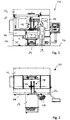
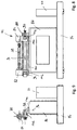
- a prior art finishing device is in the Figures 1 and 2 and denoted there as a whole by the reference numeral 10.
- the finishing device 10 is designed in the form of a machine tool which is set up on an installation surface 12.
- the finishing device 10 comprises a foundation 14 and a protective hood 16 for delimitation an interior.
- a plurality of finishing tools 18 and a workpiece 20 are arranged in the interior of the machine tool.
- the finishing device 10 comprises a splash guard 22 in the form of a housing wall as well as a workpiece transport system 24, by means of which workpieces 20 can be introduced into the interior from a front side of the finishing device 10 and transported away again from the interior.
- sliding elements 26 are provided which are part of the protective hood 16 and can be moved in such a way that an access opening is created on the front of the finishing device 10.
- the finishing tools 18 In the course of preparing the production of a workpiece lot, it is necessary to adapt the finishing tools 18 to the geometry of a workpiece 20 with regard to their position and alignment. The setup processes required for this are made more difficult by the splash guard 22 and the workpiece transport system 24, among other things. It is particularly difficult for an operator 28 to set finishing tools which are covered by adjacent finishing tools.
- the Figures 1 and 2 two finishing tools 18 shown by way of example are usually part of a larger group of finishing tools. For example, a total of nine finishing tools, which are arranged closely adjacent to one another, are used for machining a crankshaft for a four-cylinder in-line engine. Five finishing tools are used to machine main bearings on the crankshaft and four finishing tools are used to machine connecting rod bearings on the crankshaft.
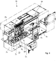
- a finishing device according to the invention in the form of a machine tool is shown in FIG Figures 3 to 5 and denoted there as a whole by the reference numeral 30.
- the finishing device 30 is set up on an installation surface 32 and comprises a foundation 34 and a protective hood 36 for delimiting an interior of the machine tool.
- the interior of the finishing device 30 comprises a work area 38 and an additional area 40 arranged outside the work area 38.
- the work area 38 is used to finish-machine a workpiece 42, in particular a crankshaft or camshaft.
- finishing tools 44, 46 are provided which are arranged adjacent to one another and machine workpiece surfaces of the workpiece 42 that are adjacent to one another. To improve clarity, only two finishing tools are shown in the drawing, namely a first finishing tool 44 for machining a main bearing of the workpiece 42 and a second finishing tool 46 for machining a connecting rod bearing of the workpiece 42.
- the finishing tools 44, 46 are each held displaceably on a slide 48, which in turn can be displaced along a slide guide 50.
- the carriage guide 50 is straight.
- the total length of the slide guide 50 corresponds to the sum of the respective individual lengths of the working area 38 and the additional area 40.
- the finishing device 30 has, assigned to the work area 38, a splash guard 52 in the form of a wall, which is part of the protective hood 36.
- the finishing device 30 also has a workpiece transport system 54 which, starting from the work area 38, protrudes forwards relative to the protective hood 36 and thus, like the splash guard 52, makes access to the work area 38 of the finishing device 30 more difficult.
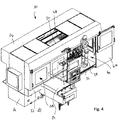
- the additional area 40 comprises a platform 56 arranged on the floor side with a step surface for an operator 58.
- the additional area 40 is also assigned at least one door 60, which is preferably large enough for the operator 58 to be able to enter the additional area 40.
- an opening that can be released by the door 60 has a minimum height of 1.60 m, preferably 2 m.
- a minimum width of the opening that can be released by the door 60 is, for example, 0.8 m, preferably 1.2 m.
- the finishing tools are removed from the work area 38 (cf. Figure 3 ) in the Additional area 40 (cf. Figures 4 , 5 and 6th ) spent.
- a motor drive not shown for reasons of clarity, is provided, which drives a spindle nut assigned to the slide 48, for example via a threaded spindle, and thus moves the slide 48 along the slide guide 50.
- the finishing tools 44, 46 can also be transported between the work area and the additional area 40 with the aid of pneumatic or hydraulic cylinders.
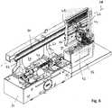
- the slide guide 50 is arranged in the upper region of the interior of the finishing device 30 and is supported, for example, on three support columns 62, 64 and 66.
- One column (62 or 66) is preferably assigned to one of the areas 38 and 40, with a central column 64 being arranged in the transition area between the work area 38 and the additional area 40.
- the slide guide 50 defines a transport axis 68 along which the slide 48 can be displaced between the work area 38 and the additional area 40.
- a workpiece holder 70 assigned to the work area comprises a headstock 74 serving as a rotary drive and a tailstock 76.
- headstock 74 serving as a rotary drive
- tailstock 76 During the finishing machining of a workpiece 42, it rotates about a workpiece axis 78.
- An oscillating back and forth movement is superimposed on this rotational movement.
- an oscillation drive 80 is provided which moves a composite of spindle material 74, workpiece 42 and tailstock 76 back and forth in a manner known per se in a direction parallel to workpiece axis 78.
- the workpiece holder 72 of the additional area 40 also has a headstock 82 and a tailstock 84, so that a setup shaft 104 corresponding to the workpiece 42 (cf. Fig. 10 ) can be arranged in the additional workpiece holder 72.
- the headstock 82 of the additional workpiece holder 72 is preferably designed such that there is one between the headstock 82 and the tailstock 84 accommodated setup shaft 104 is rotatably mounted, but cannot be actively driven in the direction of rotation.
- the setup shaft 104 is only received between the tips of the headstock 82 and the tailstock 84 and is also fixed in the direction of rotation.
- the additional workpiece holder 72 is mounted on a frame 86, so that when a workpiece 42 is arranged in the additional workpiece holder 72, a workpiece axis 78 of the workpiece 42 is at least substantially aligned with a workpiece axis 78 of a workpiece 42 which is on or in the workpiece holder 70 of the work area 38 is held.
- the workpiece holder 72 of the additional area 40 simulates the workpiece holding surfaces of the workpiece holder 70 of the work area 38.
- the headstock 82 and / or the tailstock 84 of the additional workpiece holder 72 can be displaced parallel to the transport axis 68 of the finishing device 30 and are held on a holding rail 88.
- a manually operated setting wheel 90 is provided to adjust the tailstock 84 along an adjustment axis 92 aligned parallel to the transport axis 68.
- the headstock 82 is fastened to the holding rail 88 by means of an elongated screw connection 94.
- Corresponding adjustment devices can be provided for positioning the headstock 82 and / or the tailstock 84 along a vertical adjusting axis 96 and / or along a horizontal adjusting axis 98.
- an adjustment is made along a vertical adjusting axis 96 by using a spacer plate 100 ground to size or in a horizontal direction by using a ground spacer plate 102 (cf. Figure 9 ).
- a smooth, cylindrical alignment shaft (not shown in the drawing) is inserted in the work area 38 in the workpiece holder 70 between tips of the Headstock 74 and tailstock 76 clamped.
- the alignment shaft which is fixed in the direction of rotation, is then traversed along its length with a dial gauge, preferably within two mutually perpendicular measuring planes. In this way, a position and attitude error is determined.
- This position error is a deviation from a perfectly concentric and parallel alignment of the axes of rotation of the headstock 74 and the tailstock 76 relative to one another.
- the same alignment shaft is then received in the workpiece holder 72 of the additional area 40 between the tips of the headstock 82 and the tailstock 84 and is also traversed there with a dial gauge as described above.
- the position and position error associated with the additional area 40 determined in this way is compared with the position and position error associated with the work area 38.
- the positions of the headstock 82 and / or the tailstock 84 of the additional workpiece holder 72 are then set along the adjustment axes 92, 96 and / or 98 until the position error associated with the additional area 40 matches the position error associated with the work area 38 .
- a setup process is described by way of example, which can be carried out in the additional area 40 to prepare a finishing machining of a workpiece 42 in the work area 38.
- a set-up workpiece in the form of a set-up shaft 104 can be positioned, which has a plurality of axial stops 108, 110 along its axis 106 (cf. Figure 10 ). With regard to their spacing, these axial stops 108, 110 are matched to corresponding spacings from surface sections to be machined of a workpiece 42, which is designed in particular in the form of a crankshaft and comprises main bearings 112 and connecting rod bearings 114 (cf. Figure 11 ).
- the in Figure 10 illustrated embodiment are two finishing tools 46, each for machining a main bearing 112 of the workpiece 42 are formed, positioned at their spacing 116 relative to one another.
- a finishing tool 46 is brought into contact with one of the stops 108, 110.
- the finishing tools 46 are then fixed on the slide 48 in the state aligned relative to one another in the axial direction.
- the finishing tools 46 When the finishing tools 46 are then brought from the additional area 40 into the work area 38 by means of the carriage 48, the finishing tools 46 have a relative distance from one another, which is already attached to the geometry of the workpiece 42 to be machined, so that an alignment process in this regard is carried out in the work area 38 no longer needs to be done.
- the set-up shaft 104 preferably also serves to align pressure shells assigned to the finishing tools 44, 46, which press a finishing belt against a surface of the workpiece 42 to be machined, relative to a pressure shell carrier (in particular a pressure arm).
- a pressure shell carrier in particular a pressure arm.
- an adjusting device is provided for fastening a pressure shell to a pressure arm.
- an inclination-adjustable screw connection is provided for fastening a pressure shell to a pressure arm, this inclination-adjustable screw connection forming the setting device.
- Such an inclination-adjustable screw connection preferably comprises spherical disks and conical sockets, which can be adjusted in their inclination relative to one another, so that an axis of a screw which penetrates the spherical disk and conical socket is also adjustable in its inclination in order to incline the pressure shell relative to the pressure arm define. In this way, manufacturing and assembly errors in the overall system, which add up at the interface to the workpiece 42, can be compensated.
Landscapes
- Engineering & Computer Science (AREA)
- Mechanical Engineering (AREA)
- Turning (AREA)
- Constituent Portions Of Griding Lathes, Driving, Sensing And Control (AREA)
- Grinding And Polishing Of Tertiary Curved Surfaces And Surfaces With Complex Shapes (AREA)
Description
Die Erfindung betrifft eine Finishvorrichtung zur Finishbearbeitung eines Werkstücks, insbesondere einer Kurbelwelle oder einer Nockenwelle, mit einem Werkstückhalter und mit einem Rotationsantrieb zur Rotation des Werkstücks um dessen Werkstückachse, mit mindestens einem ersten Finishwerkzeug zur Bearbeitung eines zu der Werkstückachse konzentrischen Hauptlagers und mit mindestens einem zweiten Finishwerkzeug zur Bearbeitung eines Zusatzlagers.The invention relates to a finishing device for finishing a workpiece, in particular a crankshaft or a camshaft, with a workpiece holder and with a rotary drive for rotating the workpiece about its workpiece axis, with at least one first finishing tool for machining a main bearing concentric to the workpiece axis and with at least one second Finishing tool for machining an additional bearing.
Eine solche Finishvorrichtung ist aus der
Die Finishbearbeitung eines Werkstücks erzeugt ein Werkstück mit kleinsten Oberflächentoleranzen. Voraussetzung hierfür ist, dass die Finishwerkzeuge exakt relativ zu dem zu bearbeitenden Werkstück ausgerichtet werden. Bei Kurbelwellen oder Nockenwellen mit mehreren Lagern kommt hinzu, dass in Achsrichtung des Werkstücks gesehen zueinander parallel angeordnete Finishwerkzeuge in ihrem Abstand relativ zueinander exakt eingestellt werden müssen, damit die Finishbearbeitung zueinander benachbarter Lagerflächen exakt dem Stichmaß der Kurbelwelle oder Nockenwelle entsprechend durchgeführt werden kann.The finishing of a workpiece creates a workpiece with the smallest surface tolerances. The prerequisite for this is that the finishing tools are precisely aligned relative to the workpiece to be machined. In the case of crankshafts or camshafts with multiple bearings, finishing tools that are arranged parallel to one another, viewed in the axial direction of the workpiece, must be precisely adjusted in terms of their spacing relative to one another so that the finish machining of adjacent bearing surfaces can be carried out exactly according to the pitch of the crankshaft or camshaft.
Die vorstehend beschriebenen Anforderungen erfordern eine exakte Ausrichtung des Werkstücks in dem Werkstückhalter und eine exakte Ausrichtung der Finishwerkzeuge relativ zu dem Werkstück.The requirements described above require an exact alignment of the workpiece in the workpiece holder and an exact alignment of the finishing tools relative to the workpiece.
Darüber hinaus unterliegen die Finishwerkzeuge einem Verschleiß, sodass diese in regelmäßigen Abständen ausgetauscht werden müssen.In addition, the finishing tools are subject to wear, so that they have to be replaced at regular intervals.
Die vorstehend beschriebenen Vorgänge erfordern eine möglichst gute Zugänglichkeit zu den Finishwerkzeugen, welche bei den bekannten Finishvorrichtungen jedoch nicht immer gegeben ist. Beispielsweise behindern Werkstücktransportsysteme und/oder Spritzschutzeinrichtungen einen freien Zugang zu den Finishwerkzeugen. Dies hat zur Folge, dass Wartungs- und/oder Einstellarbeiten erschwert sein können. Eine Finishvorrichtung mit den Merkmalen des Oberbegriffs des Patentanspruchs 1 ist aus der
Hiervon ausgehend liegt der vorliegenden Erfindung die Aufgabe zugrunde, eine Finishvorrichtung anzugeben, mit welcher die vorstehend beschriebenen Nachteile vermieden werden.Proceeding from this, the present invention is based on the object of specifying a finishing device with which the disadvantages described above are avoided.
Diese Aufgabe wird bei einer Finishvorrichtung mit den Merkmalen des Patentanspruchs 1 erfindungsgemäß durch die kennzeichnenden Merkmale des Patentanspruchs 1 gelöst.In the case of a finishing device with the features of claim 1, this object is achieved according to the invention by the characterizing features of claim 1.
Erfindungsgemäß ist vorgesehen, dass die Zugänglichkeit der Finishwerkzeuge dadurch vereinfacht wird, dass diese außerhalb eines Arbeitsbereichs in einem Zusatzbereich positionierbar sind, sodass die dort positionierten Finishwerkzeuge besonders gut zugänglich sind. Dies vereinfacht die Durchführung von Wartungsarbeiten an den Finishwerkzeugen.According to the invention, it is provided that the accessibility of the finishing tools is simplified in that they can be positioned outside a work area in an additional area, so that the finishing tools positioned there are particularly easily accessible. This simplifies maintenance work on the finishing tools.
Erfindungsgemäß ist in dem Zusatzbereich ein zusätzlicher Werkstückhalter angeordnet. Dies ermöglicht es, in dem Zusatzbereich die in dem Arbeitsbereich für ein bestimmtes Werkstück vorhandene Arbeitssituation nachzubilden, sodass Einrichtvorgänge in dem Zusatzbereich durchgeführt werden können. Beispielsweise können die Finishwerkzeuge hinsichtlich ihres Abstands relativ zueinander und/oder hinsichtlich ihrer Lage relativ zu einem zu bearbeitenden Werkstück in dem Zusatzbereich eingestellt werden und anschließend in den Arbeitsbereich gebracht werden. Die in dem gut zugänglichen Zusatzbereich durchgeführten Einstellarbeiten müssen dann in dem schlecht zugänglichen Arbeitsbereich nicht mehr durchgeführt werden.According to the invention, an additional workpiece holder is arranged in the additional area. This makes it possible to simulate the work situation existing in the work area for a specific workpiece in the additional area, so that setting-up processes can be carried out in the additional area. For example, the finishing tools can be adjusted in terms of their spacing relative to one another and / or in terms of their position relative to a workpiece to be machined in the additional area and then brought into the work area. The adjustment work carried out in the easily accessible additional area then no longer has to be carried out in the poorly accessible work area.
Besonders vorteilhaft ist es, wenn der zusätzliche Werkstückhalter hinsichtlich seiner mit einem Werkstück zusammenwirkenden Werkstückhalteflächen (insbesondere kegelförmige Spitzen) baugleich zu dem Werkstückhalter des Arbeitsbereiches ist.It is particularly advantageous if the additional workpiece holder interacts with a workpiece with regard to its co-operation Workpiece holding surfaces (in particular conical tips) is identical to the workpiece holder of the work area.
Besonders bevorzugt ist es, dass der zusätzliche Werkstückhalter einen Spindelstock und einen Reitstock umfasst, sodass ein Werkstück oder eine Einrichtwelle in dem Zusatzbereich anordenbar und dort zwischen dem Spindelstock und dem Reitstock des zusätzlichen Werkstückhalters aufnehmbar ist.It is particularly preferred that the additional workpiece holder comprises a headstock and a tailstock, so that a workpiece or a set-up shaft can be arranged in the additional area and can be received there between the headstock and the tailstock of the additional workpiece holder.
Insbesondere ist es bevorzugt, dass ein Spindelstock und ein Reitstock des Werkzeughalters des Arbeitsbereichs relativ zueinander ausgerichtet sind und dass der Spindelstock und der Reitstock des zusätzlichen Werkstückhalters in identischer Weise relativ zueinander ausgerichtet oder ausrichtbar sind. Dies vereinfacht die Einrichtung der Finishwerkzeuge.In particular, it is preferred that a headstock and a tailstock of the tool holder of the work area are aligned relative to one another and that the headstock and the tailstock of the additional workpiece holder are aligned or can be aligned relative to one another in an identical manner. This simplifies the setup of the finishing tools.
Für eine besonders hohe Arbeitsgenauigkeit ist es bevorzugt, dass der Spindelstock und der Reitstock des zusätzlichen Werkstückhalters abweichend von einer zueinander perfekt konzentrischen und parallelen Ausrichtung ihrer Drehachsen denselben Versatz und dieselbe Neigung relativ zueinander aufweisen wie die Drehachsen des Spindelstocks und des Reitstocks des Werkstückhalters des Arbeitsbereichs. Dies bedeutet, dass die Positions- und Lagefehler des Spindelstocks und des Reitstocks des Werkstückhalters des Arbeitsbereichs in exakter Weise auf den Spindelstock und den Reitstock des zusätzlichen Werkstückhalters übertragen und von diesem nachgebildet werden.For a particularly high working accuracy, it is preferred that the headstock and the tailstock of the additional workpiece holder, deviating from a perfectly concentric and parallel alignment of their axes of rotation, have the same offset and the same inclination relative to one another as the axes of rotation of the headstock and the tailstock of the workpiece holder of the work area. This means that the positional and positional errors of the headstock and the tailstock of the workpiece holder of the work area are transferred in an exact manner to the headstock and the tailstock of the additional workpiece holder and are simulated by the latter.
Zur Ermittlung eines Positions- und Lagefehlers des Spindelstocks und des Reitstocks des Werkstückhalters des Arbeitsbereichs ist es möglich, eine glatte Welle ("Ausrichtwelle") zwischen dem Spindelstock und dem Reitstock des Werkstückhalters des Arbeitsbereichs einzuspannen und die Oberfläche der glatten Welle mit einer Messuhr abzufahren, vorzugsweise innerhalb von zwei unterschiedlichen Messebenen, welche insbesondere zueinander senkrecht sind.To determine a position error of the headstock and the tailstock of the workpiece holder of the work area, it is possible to clamp a smooth shaft ("alignment shaft") between the headstock and the tailstock of the workpiece holder of the work area and to trace the surface of the smooth shaft with a dial gauge, preferably within two different measuring planes, which in particular are perpendicular to one another.
Zur Anpassung der Position und/oder Lage des Spindelstocks und/oder des Reitstocks des zusätzlichen Werkstückhalters ist es bevorzugt, wenn der Spindelstock und/oder der Reitstock entlang von mindestens zwei, vorzugsweise drei zueinander senkrechten Stellachsen in ihrer Position einstellbar ist oder sind.To adjust the position and / or location of the headstock and / or the tailstock of the additional workpiece holder, it is preferred if the headstock and / or the tailstock along at least two, preferably three mutually perpendicular adjusting axes is or are adjustable in their position.
Dabei entspricht beispielsweise eine der Stellachsen einer jeweiligen Drehachse des Spindelstocks bzw. des Reitstocks. Andere Stellachsen ermöglichen eine Anpassung der Position des Spindelstocks bzw. des Reitstocks in Höhen- und/oder in Seitenrichtung.For example, one of the adjusting axes corresponds to a respective axis of rotation of the headstock or the tailstock. Other adjusting axes enable the position of the headstock or tailstock to be adjusted in height and / or in lateral direction.
Zur Vereinfachung des zusätzlichen Werkstückhalters ist es vorteilhaft, wenn der Spindelstock des zusätzlichen Werkstückhalters keinen Rotationsantrieb aufweist. Dieser ist nicht erforderlich, wenn in dem Zusatzbereich keine Werkstückbearbeitung sondern lediglich Wartungs- und/oder Einstellarbeiten durchgeführt werden.To simplify the additional workpiece holder, it is advantageous if the headstock of the additional workpiece holder does not have a rotary drive. This is not necessary if no workpiece machining but only maintenance and / or adjustment work is carried out in the additional area.
Zur Vereinfachung der Handhabung der Finishwerkzeuge ist vorgesehen, dass diese an einem Finishwerkzeughalter gehalten sind, der entlang der Transportachse bewegbar angetrieben ist. Die Transportachse wird konstruktiv beispielsweise durch eine Schlittenführung ausgebildet, entlang welcher ein Schlitten verfahrbar ist. Dieser Schlitten ist Teil des Finishwerkzeughalters oder bildet den Finishwerkzeughalter. Insbesondere ist die Transportachse gradlinig, wodurch der Transport der Finishwerkzeuge vereinfacht wird.To simplify the handling of the finishing tools, it is provided that they are held on a finishing tool holder which is driven movably along the transport axis. The transport axis is constructed, for example, by a slide guide along which a slide can be moved. This carriage is part of the finishing tool holder or forms the finishing tool holder. In particular, the transport axis is straight, which simplifies the transport of the finishing tools.
Die vorstehend beschriebenen Maßnahmen sind besonders vorteilhaft, wenn dem Arbeitsbereich der Finishvorrichtung ein Werkstücktransportsystem zugeordnet ist. Ein solches Werkstücktransportsystem vereinfacht die Zuführung unbearbeiteter Werkstücke und den Abtransport finishend bearbeiteter Werkstücke.The measures described above are particularly advantageous if a workpiece transport system is assigned to the work area of the finishing device. Such a workpiece transport system simplifies the supply of unprocessed workpieces and the removal of finished workpieces.
Vorteilhaft ist es ferner, wenn dem Arbeitsbereich der Finishvorrichtung eine Spritzschutzeinrichtung zugeordnet ist, sodass die Bereiche außerhalb des Arbeitsbereichs, vorzugsweise einschließlich des Zusatzbereichs, vor Kühlflüssigkeit und/oder Schmierflüssigkeit geschützt sind.It is also advantageous if a spray protection device is assigned to the work area of the finishing device, so that the areas outside the work area, preferably including the additional area, are protected from cooling liquid and / or lubricating liquid.
Besondere Vorteile ergeben sich, wenn die Finishwerkzeuge Finishbänder umfassen oder als solche ausgebildet sind. Finishbänder erfordern eine vergleichsweise aufwändige Handhabung zur Führung eines Finishbandabschnitts an das Werkstück heran, im Bereich des Kontakts mit dem Werkstück und von dem zu bearbeitenden Werkstück weg. Die hierfür erforderlichen Finishbandführungen sind bei der erfindungsgemäßen Finishvorrichtung für Wartungsvorgänge besonders gut zugänglich.Particular advantages result when the finishing tools include finishing belts or are designed as such. Finishing belts require a comparatively complex handling for guiding a finishing belt section towards the workpiece in the area of contact with the workpiece and away from the workpiece to be machined. The finishing tape guides required for this are particularly easily accessible for maintenance operations in the finishing device according to the invention.
Die erfindungsgemäße Finishvorrichtung eignet sich insbesondere zur Bearbeitung von Kurbelwellen mit Hauptlagern und Zusatzlagern in Form von Pleuellagern und zur Bearbeitung von Nockenwellen mit Hauptlagern und Zusatzlagern in Form von Nockenumfangsflächen.The finishing device according to the invention is particularly suitable for machining crankshafts with main bearings and additional bearings in the form of connecting rod bearings and for machining camshafts with main bearings and additional bearings in the form of cam circumferential surfaces.
Die Erfindung betrifft auch ein Verfahren zur Einrichtung einer vorstehend beschriebenen Finishvorrichtung, welches dadurch gekennzeichnet ist, dass ein dem Werkstückhalter des Arbeitsbereichs zugeordneter Positions- und Lagefehler erfasst wird und dass der zusätzliche Werkstückhalter oder Teile davon so positioniert und/oder ausgerichtet wird oder werden, dass ein dem zusätzlichen Werkstückhalter zugeordneter Positions- und Lagefehler identisch ist zu dem Positions- und Lagefehler des Werkstückhalters des Arbeitsbereichs.The invention also relates to a method for setting up a finishing device described above, which is characterized in that a position and position error associated with the workpiece holder of the work area is detected and that the additional workpiece holder or parts thereof are positioned and / or aligned in such a way that a position and position error associated with the additional workpiece holder is identical to the position and position error of the workpiece holder of the work area.
Ein Positions- und Lagefehler eines Werkstückhalters entspricht einer Abweichung zu einer zueinander perfekt konzentrischen und parallelen Ausrichtung der zentralen Achsen eines Spindelstocks und eines Reitstocks eines Werkstückhalters relativ zueinander. Bei den zentralen Achsen des Werkstückhalters des Arbeitsbereichs handelt es sich um Drehachsen. Bei den zentralen Achsen des zusätzlichen Werkstückhalters des Zusatzbereichs handelt es sich um Drehachsen oder in Drehrichtung fixierte Halteachsen zum Halten eines Einrichtwerkstücks oder eines Werkstücks.A position error of a workpiece holder corresponds to a deviation from a perfectly concentric and parallel alignment of the central axes of a headstock and a tailstock of a workpiece holder relative to one another. The central axes of the workpiece holder of the work area are rotary axes. The central axes of the additional workpiece holder of the additional area are axes of rotation or holding axes fixed in the direction of rotation for holding a set-up workpiece or a workpiece.
Die Erfindung betrifft auch ein Verfahren zum Betrieb einer vorstehend beschriebenen Finishvorrichtung, welches dadurch gekennzeichnet ist, dass die Finishwerkzeuge in den Zusatzbereich verbracht, dort insbesondere mittels eines Einrichtwerkstücks (alternativ hierzu mittels eines Werkstücks) ausgerichtet werden, anschließend in ihrem ausgerichteten Zustand in den Arbeitsbereich verbracht werden und dort zur finishenden Bearbeitung eines Werkstücks verwendet werden.The invention also relates to a method for operating a finishing device described above, which is characterized in that the finishing tools are brought into the additional area, there are aligned in particular by means of a setup workpiece (alternatively by means of a workpiece), and then brought into the work area in their aligned state and are used there for the finishing machining of a workpiece.
Weitere Merkmale und Vorteile der Erfindung sind Gegenstand der nachfolgenden Beschreibung und der zeichnerischen Darstellung eines bevorzugten Ausführungsbeispiels.
-
Fig. 1 eine Vorderansicht einer vorbekannten Finishvorrichtung; -
Fig. 2 eine Draufsicht der Finishvorrichtung gemäßFig. 1 ; -
Fig. 3 eine perspektivische Ansicht einer Ausführungsform einer erfindungsgemäßen Finishvorrichtung, mit in einem Arbeitsbereich angeordneten Finishwerkzeugen; -
Fig. 4 eine derFig. 3 entsprechende Ansicht, wobei die Finishwerkzeuge in einem Zusatzbereich angeordnet sind; -
Fig. 5 eine Vorderansicht der Finishvorrichtung gemäßFig. 3 und4 ; -
Fig. 6 eine perspektivische Ansicht der Finishvorrichtung gemäßFig. 3 und4 , ohne Schutzhaube; -
Fig. 7 eine Vorderansicht von Teilen der Finishvorrichtung gemäßFig. 3 und4 , mit einem Arbeitsbereich-Werkstückhalter und mit einem Zusatzbereich-Werkstückhalter; -
Fig. 8 eine Vorderansicht des Zusatzbereich-Werkstückhalters gemäßFig. 7 in vergrößerter Darstellung; -
Fig. 9 eine Seitenansicht des Zusatzbereich-Werkstückhalters gemäßFig. 7 und8 ; -
Fig. 10 eine Draufsicht einer Ausführungsform einer Einrichtwelle zur Anordnung im Zusatzbereich und zur Positionierung von zwei beispielhaft dargestellten Finishwerkzeugen entlang einer zentralen Achse der Einrichtwelle; und -
Fig. 11 eine Draufsicht einer Ausführungsform eines mit der Einrichtwelle korrespondierenden Werkstücks zur Anordnung im Arbeitsbereich, mit entlang einer zentralen Achse des Werkstücks relativ zueinander positionierten Finishwerkzeugen gemäßFig. 10 .
-
Fig. 1 a front view of a prior art finishing device; -
Fig. 2 a top view of the finishing device according toFig. 1 ; -
Fig. 3 a perspective view of an embodiment of a finishing device according to the invention, with finishing tools arranged in a work area; -
Fig. 4 one of theFig. 3 corresponding view, wherein the finishing tools are arranged in an additional area; -
Fig. 5 a front view of the finishing device according to FIGFig. 3 and4th ; -
Fig. 6 a perspective view of the finishing device according to FIGFig. 3 and4th , without protective cover; -
Fig. 7 a front view of parts of the finishing device according to FIGFig. 3 and4th , with a work area workpiece holder and with an additional area workpiece holder; -
Fig. 8 FIG. 3 is a front view of the auxiliary area workpiece holder according to FIGFig. 7 in an enlarged view; -
Fig. 9 a side view of the auxiliary area workpiece holder according to FIGFig. 7 and8th ; -
Fig. 10 a plan view of an embodiment of a setup shaft for the arrangement in the additional area and for the positioning of two finishing tools shown by way of example along a central axis of the setup shaft; and -
Fig. 11 a plan view of an embodiment of a workpiece corresponding to the setup shaft for arrangement in the work area, with finishing tools positioned relative to one another along a central axis of the workpiece according to FIGFig. 10 .
Eine vorbekannte Finishvorrichtung ist in den
Die Finishvorrichtung 10 umfasst einen Spritzschutz 22 in Form einer Gehäusewand sowie ein Werkstücktransportsystem 24, mittels welchem Werkstücke 20 von einer Vorderseite der Finishvorrichtung 10 her in den Innenraum eingebracht und aus dem Innenraum wieder abtransportiert werden können.The finishing
Für einen Zugang zu dem Innenraum der Finishvorrichtung 10 sind Verschiebeelemente 26 vorgesehen, welche Teil der Schutzhaube 16 sind und sich so verschieben lassen, dass an der Vorderseite der Finishvorrichtung 10 eine Zugangsöffnung entsteht.For access to the interior of the finishing
Im Zuge der Vorbereitung der Fertigung eines Werkstückloses ist es erforderlich, die Finishwerkzeuge 18 hinsichtlich ihrer Position und Ausrichtung an die Geometrie eines Werkstücks 20 anzupassen. Die hierfür erforderlichen Einrichtvorgänge sind unter anderem durch den Spritzschutz 22 und das Werkstücktransportsystem 24 erschwert. Für eine Bedienperson 28 ist es insbesondere schwierig, Finishwerkzeuge einzustellen, welche von benachbarten Finishwerkzeugen verdeckt sind. In diesem Zusammenhang wird angemerkt, dass die in den
Eine erfindungsgemäße Finishvorrichtung in Form einer Werkzeugmaschine ist in
Der Innenraum der Finishvorrichtung 30 umfasst einen Arbeitsbereich 38 und einen außerhalb des Arbeitsbereichs 38 angeordneten Zusatzbereich 40. Der Arbeitsbereich 38 dient dazu, ein Werkstück 42, insbesondere eine Kurbel- oder Nockenwelle, finishend zu bearbeiten. Hierfür sind Finishwerkzeuge 44, 46 vorgesehen, welche benachbart zueinander angeordnet sind und zueinander benachbarte Werkstückflächen des Werkstücks 42 bearbeiten. Zur Verbesserung der Übersichtlichkeit sind in der Zeichnung lediglich zwei Finishwerkzeuge dargestellt, nämlich ein erstes Finishwerkzeug 44 zur Bearbeitung eines Hauptlagers des Werkstücks 42 und ein zweites Finishwerkzeug 46 zur Bearbeitung eines Pleuellagers des Werkstücks 42.The interior of the finishing
Die Finishwerkzeuge 44, 46 sind jeweils verschiebbar an einem Schlitten 48 gehalten, welcher seinerseits entlang einer Schlittenführung 50 verschiebbar ist. Die Schlittenführung 50 ist gradlinig. Die Gesamtlänge der Schlittenführung 50 entspricht der Summe der jeweiligen Einzellängen des Arbeitsbereichs 38 und des Zusatzbereichs 40.The
Die Finishvorrichtung 30 weist dem Arbeitsbereich 38 zugeordnet einen Spritzschutz 52 in Form einer Wand auf, welche Teil der Schutzhaube 36 ist. Die Finishvorrichtung 30 weist ferner ein Werkstücktransportsystem 54 auf, welches ausgehend von dem Arbeitsbereich 38 nach vorne hin relativ zu der Schutzhaube 36 herausragt und somit, wie auch der Spritzschutz 52, einen Zugang zu dem Arbeitsbereich 38 der Finishvorrichtung 30 erschwert.The finishing
Der Zusatzbereich 40 umfasst ein bodenseitig angeordnetes Podest 56 mit einer Trittfläche für eine Bedienperson 58.The
Dem Zusatzbereich 40 ist ferner mindestens eine Tür 60 zugeordnet, welche vorzugsweise so groß ist, dass die Bedienperson 58 den Zusatzbereich 40 betreten kann. Beispielsweise weist eine von der Tür 60 freigebbare Öffnung eine Mindesthöhe von 1,60 m, vorzugsweise von 2 m auf auf. Eine Mindestbreite der von der Tür 60 freigebbaren Öffnung beträgt beispielsweise 0,8 m, vorzugsweise 1,2 m.The
Zur Einrichtung und/oder Wartung der Finishwerkzeuge 44, 46 werden die Finishwerkzeuge aus dem Arbeitsbereich 38 (vgl.
Die Schlittenführung 50 ist im oberen Bereich des Innenraums der Finishvorrichtung 30 angeordnet und beispielsweise auf drei Abstützsäulen 62, 64 und 66 abgestützt. Vorzugsweise ist jeweils eine Säule (62 bzw. 66) jeweils einem der Bereiche 38 und 40 zugeordnet, wobei eine zentrale Säule 64 im Übergangsbereich zwischen Arbeitsbereich 38 und Zusatzbereich 40 angeordnet ist.The
Die Schlittenführung 50 definiert eine Transportachse 68, entlang welcher der Schlitten 48 zwischen dem Arbeitsbereich 38 und dem Zusatzbereich 40 verschiebbar ist.The
Nachfolgend werden unter Bezugnahme auf die
Der Werkstückhalter 72 des Zusatzbereichs 40 weist ebenfalls einen Spindelstock 82 und einen Reitstock 84 auf, sodass eine zu dem Werkstück 42 korrespondierende Einrichtwelle 104 (vgl.
Der zusätzliche Werkstückhalter 72 ist auf einem Gestell 86 montiert, sodass bei Anordnung eines Werkstücks 42 in dem zusätzlichen Werkstückhalter 72 eine Werkstückachse 78 des Werkstücks 42 zumindest im Wesentlichen mit einer Werkstückachse 78 eines Werkstücks 42 fluchtet, welches an oder in dem Werkstückhalter 70 des Arbeitsbereiches 38 gehalten ist. Mit anderen Worten: Der Werkstückhalter 72 des Zusatzbereichs 40 bildet die Werkstückhalteflächen des Werkstückhalters 70 des Arbeitsbereichs 38 nach.The
Der Spindelstock 82 und/oder der Reitstock 84 des zusätzlichen Werkstückhalters 72 sind parallel zu der Transportachse 68 der Finishvorrichtung 30 verschiebbar und an einer Halteschiene 88 gehalten. Zur Verstellung des Reitstocks 84 entlang einer parallel zu der Transportachse 68 ausgerichteten Verstellachse 92 ist ein handbetätigbares Einstellrad 90 vorgesehen. Der Spindelstock 82 ist zwecks Einstellung längs der Stellachse 92 mittels einer Langlochverschraubung 94 an der Halteschiene 88 befestigt.The
Zur Positionierung des Spindelstocks 82 und/oder des Reitstocks 84 entlang einer vertikalen Stellachse 96 und/oder entlang einer horizontalen Stellachse 98 können entsprechende Verstelleinrichtungen vorgesehen sein. Im einfachsten Fall erfolgt eine Einstellung entlang einer vertikalen Stellachse 96 durch Verwendung einer auf Maß geschliffenen Abstandsplatte 100 bzw. in einer horizontalen Richtung durch Verwendung einer geschliffenen Abstandsplatte 102 (vgl.
Zur Festlegung der Position und Lage des Spindelstocks 82 und/oder des Reitstocks 84 des zusätzlichen Werkstückhalters 72 wird eine (in der Zeichnung nicht dargestellte) glatte, zylindrische Ausrichtwelle in dem Arbeitsbereich 38 in den Werkstückhalter 70 zwischen Spitzen des Spindelstocks 74 und des Reitstocks 76 eingespannt. Anschließend wird die in Drehrichtung fixierte Ausrichtwelle entlang ihrer Länge mit einer Messuhr abgefahren, vorzugsweise innerhalb von zwei zueinander senkrechten Messebenen. Auf diese Weise wird ein Positions- und Lagefehler ermittelt. Bei diesem Positions- und Lagefehler handelt es sich um eine Abweichung zu einer zueinander perfekt konzentrischen und parallelen Ausrichtung der Drehachsen des Spindelstocks 74 und des Reitstocks 76 relativ zueinander.To determine the position and location of the
Anschließend wird dieselbe Ausrichtwelle in dem Werkstückhalter 72 des Zusatzbereichs 40 zwischen Spitzen des Spindelstocks 82 und des Reitstocks 84 aufgenommen und auch dort wie vorstehend beschrieben mit einer Messuhr abgefahren. Der auf diese Weise ermittelte, dem Zusatzbereich 40 zugeordnete Positions- und Lagefehler wird mit dem dem Arbeitsbereich 38 zugeordneten Positions- und Lagefehler verglichen.The same alignment shaft is then received in the
Anschließend werden die Positionen des Spindelstocks 82 und/oder des Reitstocks 84 des zusätzlichen Werkstückhalters 72 entlang der Verstellachsen 92, 96 und/oder 98 eingestellt, bis der dem Zusatzbereich 40 zugeordnete Positions- und Lagefehler mit dem dem Arbeitsbereich 38 zugeordneten Positions- und Lagefehler übereinstimmt.The positions of the
Nachfolgend wird beispielhaft ein Einrichtvorgang beschrieben, welcher in dem Zusatzbereich 40 durchgeführt werden kann, zur Vorbereitung einer finishenden Bearbeitung eines Werkstücks 42 in dem Arbeitsbereich 38.In the following, a setup process is described by way of example, which can be carried out in the
In dem Zusatzbereich 40 kann ein Einrichtwerkstück in Form einer Einrichtwelle 104 positioniert werden, welches entlang seiner Achse 106 eine Mehrzahl von Axialanschlägen 108, 110 aufweist (vgl.
Bei dem in
Die Einrichtwelle 104 dient vorzugsweise auch dazu, den Finishwerkzeugen 44, 46 zugeordnete Andrückschalen, welche ein Finishband gegen ein zu bearbeitende Oberfläche des Werkstücks 42 drücken, relativ zu einem Andrückschalenträger (insbesondere einem Andrückarm) auszurichten. Hierfür ist es bevorzugt, wenn zur Befestigung einer Andrückschale an einem Andrückarm eine Einstelleinrichtung vorgesehen ist. Beispielsweise ist eine neigungseinstellbare Verschraubung zur Befestigung einer Andrückschale an einem Andrückarm vorgesehen, wobei diese neigungseinstellbare Verschraubung die Einstelleinrichtung bildet. Eine solche neigungseinstellbare Verschraubung umfasst vorzugsweise Kugelscheiben und Kegelpfannen, welche relativ zueinander in ihrer Neigung eingestellt werden können, sodass eine Achse einer Schraube, welche die Kugelscheibe und Kegelpfanne durchsetzt, ebenfalls in ihrer Neigung einstellbar ist, um eine Neigung der Andrückschale relativ zu dem Andrückarm zu definieren. Auf diese Weise können Fertigungs- und Montagefehler im Gesamtsystem, die sich an der Schnittstelle zu dem Werkstück 42 aufsummieren, kompensiert werden.The set-up
Es ist auch denkbar, anstelle einer Einrichtwelle 104 ein Werkstück 42 zur Durchführung der vorstehend beschriebenen Ausrichtvorgänge (Einstellung des Abstands der Finishwerkzeuge, Ausrichtung der Andrückschalen) zu verwenden.It is also conceivable to use a
Claims (12)
- Finishing device (30) for finish machining a workpiece (42), in particular a crankshaft or a camshaft, comprising a workpiece holder (70) and a rotary drive for rotating the workpiece (42) about the workpiece axis (78) thereof, comprising at least one first finishing tool (44) for machining a main bearing concentric to the workpiece axis (78) and at least one second finishing tool (46) for machining an additional bearing, wherein the finishing tools (44, 46) can be moved along a transport axis (68) which extends beyond a working area (38) defined by the workpiece holder (70) and which serves to finish machine of a workpiece (42) by means of the finishing tools (44, 46), wherein the finishing tools (44, 46) are held on a finishing tool holder which is driven in a movable manner along the transport axis (68), characterized in that the finishing tool holder with the finishing tools (44, 46) can be moved along the transport axis (68) into an additional area (40) which is arranged outside the working area (38) and in which an additional workpiece holder (72) is arranged.
- Finishing device (30) according to claim 1, characterized in that the additional workpiece holder (72) is structurally identical to the workpiece holder (70) of the working area (38) with respect to its workpiece holding surfaces interacting with a workpiece (42).
- Finishing device (30) according to claim 1 or 2, characterized in that the additional workpiece holder (72) comprises a headstock (82) and a tailstock (84).
- Finishing device (30) according to claim 3, characterized in that a headstock (74) and a tailstock (76) of the workpiece holder (70) of the working area (38) are aligned relative to one another and that the headstock (82) and the tailstock (84) of the additional workpiece holder (72) are or can be aligned in an identical manner relative to one another.
- Finishing device (30) according to either claim 3 or 4, characterized in that the headstock (82) and the tailstock (84) of the additional workpiece holder (72) deviate from having an alignment of their axes of rotation that is perfectly concentric and parallel to one another and have the same offset and the same tilt relative to one another as the axes of rotation of the headstock (74) and of the tailstock (76) of the workpiece holder (70) of the working area (38).
- Finishing device (30) according to any of claims 3 to 5, characterized in that the position of the headstock (82) and/or of the tailstock (84) of the additional workpiece holder (72) can be adjusted along adjusting axes (92, 96, 98) that are perpendicular to one another.
- Finishing device (30) according to any of claims 3 to 6, characterized in that the headstock (82) of the additional workpiece holder (72) does not have any rotary drive.
- Finishing device (30) according to any of the preceding claims, characterized in that a workpiece transport system (54) is assigned to the working area (38).
- Finishing device (30) according to any of the preceding claims, characterized in that a spray protection device (52) is assigned to the working area (38).
- Finishing device (30) according to any of the preceding claims, characterized in that the finishing tools (44, 46) comprise finishing tapes or are constructed as such.
- Method for setting up a finishing device (30) according to any of claims 2 to 10, characterized in that a positional and locational error assigned to the workpiece holder (70) of the working area (38) is detected and that the additional workpiece holder (72) or parts thereof is or are positioned and/or aligned such that a positional and locational error assigned to the additional workpiece holder (72) is identical to the positional and locational error of the workpiece holder (70) of the working area (38).
- Method for operating a finishing device (30) according to any of claims 1, 2, 4 to 10, characterized in that the finishing tools (44, 46) are moved into the additional area (40), are aligned there by means of a setup workpiece which is a setup shaft (104), or by means of a workpiece (42), wherein the setup workpiece or the workpiece (42) is arranged in the additional workpiece holder (72), wherein the workpiece holder (72) comprises a headstock (82) and a tailstock (84), wherein the finishing tools (44, 46) are subsequently moved in their aligned state into the working area (38) and are used there for finish machining a workpiece (42).
Applications Claiming Priority (1)
| Application Number | Priority Date | Filing Date | Title |
|---|---|---|---|
| PCT/EP2014/066945 WO2016019997A1 (en) | 2014-08-06 | 2014-08-06 | Finishing device for finish machining of a workpiece, in particular of a crankshaft or a camshaft |
Publications (2)
| Publication Number | Publication Date |
|---|---|
| EP3152000A1 EP3152000A1 (en) | 2017-04-12 |
| EP3152000B1 true EP3152000B1 (en) | 2021-11-10 |
Family
ID=51392229
Family Applications (1)
| Application Number | Title | Priority Date | Filing Date |
|---|---|---|---|
| EP14755037.0A Active EP3152000B1 (en) | 2014-08-06 | 2014-08-06 | Finishing device for finish machining of a workpiece, in particular of a crankshaft or a camshaft |
Country Status (5)
| Country | Link |
|---|---|
| US (1) | US10427268B2 (en) |
| EP (1) | EP3152000B1 (en) |
| KR (1) | KR102236663B1 (en) |
| CN (1) | CN106687252B (en) |
| WO (1) | WO2016019997A1 (en) |
Families Citing this family (5)
| Publication number | Priority date | Publication date | Assignee | Title |
|---|---|---|---|---|
| DE102016116161A1 (en) * | 2016-08-30 | 2018-03-01 | Supfina Grieshaber Gmbh & Co. Kg | Machine tool and method for finishing machining of workpieces |
| CN106735577B (en) * | 2016-11-09 | 2018-12-25 | 广州博研智能科技有限公司 | A kind of crankshaft deburring machine |
| CN108972230B (en) * | 2018-09-07 | 2020-11-27 | 中国工程物理研究院激光聚变研究中心 | Optical element processing apparatus and processing method |
| CN111546164B (en) * | 2020-04-25 | 2020-11-24 | 深圳市科路迪机械设备有限公司 | Circuit board grinding machine |
| CN112320245A (en) * | 2020-10-15 | 2021-02-05 | 厦门精升力科技有限公司 | Protection device of production line |
Family Cites Families (13)
| Publication number | Priority date | Publication date | Assignee | Title |
|---|---|---|---|---|
| CH670792A5 (en) * | 1985-06-29 | 1989-07-14 | Schaudt Maschinenbau Gmbh | |
| FR2727885A1 (en) * | 1994-12-09 | 1996-06-14 | Renault Automation | MACHINE TOOL FOR MACHINING CRANKSHAFTS FOR IN-LINE FOUR-CYLINDER ENGINES, ITS WORKING METHOD AND MACHINING CHAIN INCLUDING SUCH A MACHINE TOOL |
| US5951377A (en) * | 1996-08-01 | 1999-09-14 | Radtec, Inc. | Microfinishing machine |
| CN2287070Y (en) * | 1997-06-19 | 1998-08-05 | 上海浦东汉华科技工程公司 | Grinding apparatus for crankshaft necks |
| JP3558917B2 (en) * | 1999-03-19 | 2004-08-25 | 本田技研工業株式会社 | Finishing equipment for crankshafts |
| DE10144644B4 (en) * | 2001-09-11 | 2006-07-13 | Bsh Holice A.S. | Method and device for grinding centric bearing points of crankshafts |
| DE102004013192B3 (en) * | 2004-03-17 | 2005-08-25 | Erwin Junker Maschinenfabrik Gmbh | Bearing and cams grinding method e.g. for cam shaft, involves having cam shaft consisting of steel tube and cam directs tube toward grinding machine, with which after sharpening procedure directs cam shaft toward same grinding machine |
| DE102007026562B4 (en) * | 2007-06-08 | 2010-08-26 | Erwin Junker Maschinenfabrik Gmbh | Grinding center and method for simultaneously grinding multiple bearings of crankshafts |
| DE102007059926A1 (en) | 2007-12-04 | 2009-06-10 | Nagel Maschinen- Und Werkzeugfabrik Gmbh | Apparatus for finish machining peripheral surfaces of substantially rotationally symmetrical workpiece sections on wave-shaped workpieces |
| JP5550554B2 (en) * | 2008-07-10 | 2014-07-16 | シチズンマシナリーミヤノ株式会社 | Work processing apparatus and work processing method |
| US20100054887A1 (en) * | 2008-08-28 | 2010-03-04 | Feng-Tien Chen | Machine tool with a plurality of worktables |
| CN103608147B (en) * | 2012-06-15 | 2015-04-15 | 山崎马扎克公司 | Machining center |
| ES2758034T3 (en) * | 2012-08-06 | 2020-05-04 | Etxetar Sa | Machine tool |
-
2014
- 2014-08-06 KR KR1020177005398A patent/KR102236663B1/en active Active
- 2014-08-06 EP EP14755037.0A patent/EP3152000B1/en active Active
- 2014-08-06 WO PCT/EP2014/066945 patent/WO2016019997A1/en not_active Ceased
- 2014-08-06 CN CN201480080772.9A patent/CN106687252B/en active Active
- 2014-08-06 US US15/501,448 patent/US10427268B2/en active Active
Also Published As
| Publication number | Publication date |
|---|---|
| CN106687252B (en) | 2019-07-09 |
| KR102236663B1 (en) | 2021-04-06 |
| US10427268B2 (en) | 2019-10-01 |
| WO2016019997A1 (en) | 2016-02-11 |
| US20170232570A1 (en) | 2017-08-17 |
| CN106687252A (en) | 2017-05-17 |
| EP3152000A1 (en) | 2017-04-12 |
| KR20170039239A (en) | 2017-04-10 |
Similar Documents
| Publication | Publication Date | Title |
|---|---|---|
| DE10002053C2 (en) | Device for the complete production of complex work parts | |
| DE102013001675B4 (en) | Device for mounting and dismounting hydraulic cylinders | |
| DE4495551C2 (en) | Z-axis drive for a machine tool | |
| EP2855082B1 (en) | Device for sharpening tools with cutters, such as for example drills, milling tools or the like | |
| DE2442139C2 (en) | ||
| EP3152000B1 (en) | Finishing device for finish machining of a workpiece, in particular of a crankshaft or a camshaft | |
| WO2015021565A1 (en) | Machine for machining workpieces | |
| EP2835203B1 (en) | Machine tool and method for machining workpieces with at least two separate machining units | |
| DE102013225292B4 (en) | GRINDING MACHINE FOR GRINDING CENTRIC AND / OR ECCENTRIC STORAGE SPACES ON WAVE PARTS WITH A COUNTER FOR SUPPORTING THE STORES | |
| DE102008004851A1 (en) | Device for machining, in particular eroding and grinding, of cutting pieces provided with cutting edges | |
| WO2019052859A1 (en) | TOOL MAGAZINE AND METHOD FOR CHANGING TOOLS | |
| EP1068917A2 (en) | Device and method for machining crankpins | |
| DE102008027197B4 (en) | Process for processing workpiece surfaces | |
| DE69904628T2 (en) | METHOD AND DEVICE FOR GRINDING COMPOSITE COMPONENTS | |
| DE2552259A1 (en) | DEVICE FOR GRINDING INTERNAL, AXIAL PROFILES | |
| DE10135233A1 (en) | Circular machine for provision of fracture separation points in components, e.g. for production of connecting rods, has stationary inner work station and outer work stations in circulating section | |
| EP4058237A1 (en) | Circular grinding machine with dressing unit | |
| DE69510651T2 (en) | IMPROVEMENTS ON / OR IN CONNECTION WITH GRINDING MACHINES | |
| DE69308185T2 (en) | Method and device for grinding two butt-jointed rails | |
| EP0227663A1 (en) | Apparatus for machining teeth on gear wheels. | |
| DE112012002207B4 (en) | A portable tooling device for machining a lower portion of a chassis of an aircraft and method of use thereof | |
| WO2015169823A1 (en) | Device for rotatable mounting of work pieces, in particular crankshafts | |
| WO2013178452A1 (en) | Valve machining device and method for machining a valve | |
| EP2986415B1 (en) | Device and method for processing, in particular grinding, an optical workpiece | |
| DE1937003A1 (en) | Method and device for processing workpieces using remote control |
Legal Events
| Date | Code | Title | Description |
|---|---|---|---|
| STAA | Information on the status of an ep patent application or granted ep patent |
Free format text: STATUS: THE INTERNATIONAL PUBLICATION HAS BEEN MADE |
|
| PUAI | Public reference made under article 153(3) epc to a published international application that has entered the european phase |
Free format text: ORIGINAL CODE: 0009012 |
|
| STAA | Information on the status of an ep patent application or granted ep patent |
Free format text: STATUS: REQUEST FOR EXAMINATION WAS MADE |
|
| 17P | Request for examination filed |
Effective date: 20170105 |
|
| AK | Designated contracting states |
Kind code of ref document: A1 Designated state(s): AL AT BE BG CH CY CZ DE DK EE ES FI FR GB GR HR HU IE IS IT LI LT LU LV MC MK MT NL NO PL PT RO RS SE SI SK SM TR |
|
| AX | Request for extension of the european patent |
Extension state: BA ME |
|
| RIN1 | Information on inventor provided before grant (corrected) |
Inventor name: HILDEBRANDT, OLIVER |
|
| DAX | Request for extension of the european patent (deleted) | ||
| STAA | Information on the status of an ep patent application or granted ep patent |
Free format text: STATUS: EXAMINATION IS IN PROGRESS |
|
| 17Q | First examination report despatched |
Effective date: 20210222 |
|
| GRAP | Despatch of communication of intention to grant a patent |
Free format text: ORIGINAL CODE: EPIDOSNIGR1 |
|
| STAA | Information on the status of an ep patent application or granted ep patent |
Free format text: STATUS: GRANT OF PATENT IS INTENDED |
|
| INTG | Intention to grant announced |
Effective date: 20210707 |
|
| GRAS | Grant fee paid |
Free format text: ORIGINAL CODE: EPIDOSNIGR3 |
|
| GRAA | (expected) grant |
Free format text: ORIGINAL CODE: 0009210 |
|
| STAA | Information on the status of an ep patent application or granted ep patent |
Free format text: STATUS: THE PATENT HAS BEEN GRANTED |
|
| AK | Designated contracting states |
Kind code of ref document: B1 Designated state(s): AL AT BE BG CH CY CZ DE DK EE ES FI FR GB GR HR HU IE IS IT LI LT LU LV MC MK MT NL NO PL PT RO RS SE SI SK SM TR |
|
| REG | Reference to a national code |
Ref country code: GB Ref legal event code: FG4D Free format text: NOT ENGLISH |
|
| REG | Reference to a national code |
Ref country code: AT Ref legal event code: REF Ref document number: 1445620 Country of ref document: AT Kind code of ref document: T Effective date: 20211115 Ref country code: CH Ref legal event code: EP |
|
| REG | Reference to a national code |
Ref country code: DE Ref legal event code: R096 Ref document number: 502014015977 Country of ref document: DE |
|
| REG | Reference to a national code |
Ref country code: IE Ref legal event code: FG4D Free format text: LANGUAGE OF EP DOCUMENT: GERMAN |
|
| REG | Reference to a national code |
Ref country code: LT Ref legal event code: MG9D |
|
| REG | Reference to a national code |
Ref country code: NL Ref legal event code: MP Effective date: 20211110 |
|
| PG25 | Lapsed in a contracting state [announced via postgrant information from national office to epo] |
Ref country code: RS Free format text: LAPSE BECAUSE OF FAILURE TO SUBMIT A TRANSLATION OF THE DESCRIPTION OR TO PAY THE FEE WITHIN THE PRESCRIBED TIME-LIMIT Effective date: 20211110 Ref country code: LT Free format text: LAPSE BECAUSE OF FAILURE TO SUBMIT A TRANSLATION OF THE DESCRIPTION OR TO PAY THE FEE WITHIN THE PRESCRIBED TIME-LIMIT Effective date: 20211110 Ref country code: FI Free format text: LAPSE BECAUSE OF FAILURE TO SUBMIT A TRANSLATION OF THE DESCRIPTION OR TO PAY THE FEE WITHIN THE PRESCRIBED TIME-LIMIT Effective date: 20211110 Ref country code: BG Free format text: LAPSE BECAUSE OF FAILURE TO SUBMIT A TRANSLATION OF THE DESCRIPTION OR TO PAY THE FEE WITHIN THE PRESCRIBED TIME-LIMIT Effective date: 20220210 |
|
| PG25 | Lapsed in a contracting state [announced via postgrant information from national office to epo] |
Ref country code: IS Free format text: LAPSE BECAUSE OF FAILURE TO SUBMIT A TRANSLATION OF THE DESCRIPTION OR TO PAY THE FEE WITHIN THE PRESCRIBED TIME-LIMIT Effective date: 20220310 Ref country code: SE Free format text: LAPSE BECAUSE OF FAILURE TO SUBMIT A TRANSLATION OF THE DESCRIPTION OR TO PAY THE FEE WITHIN THE PRESCRIBED TIME-LIMIT Effective date: 20211110 Ref country code: PT Free format text: LAPSE BECAUSE OF FAILURE TO SUBMIT A TRANSLATION OF THE DESCRIPTION OR TO PAY THE FEE WITHIN THE PRESCRIBED TIME-LIMIT Effective date: 20220310 Ref country code: PL Free format text: LAPSE BECAUSE OF FAILURE TO SUBMIT A TRANSLATION OF THE DESCRIPTION OR TO PAY THE FEE WITHIN THE PRESCRIBED TIME-LIMIT Effective date: 20211110 Ref country code: NO Free format text: LAPSE BECAUSE OF FAILURE TO SUBMIT A TRANSLATION OF THE DESCRIPTION OR TO PAY THE FEE WITHIN THE PRESCRIBED TIME-LIMIT Effective date: 20220210 Ref country code: NL Free format text: LAPSE BECAUSE OF FAILURE TO SUBMIT A TRANSLATION OF THE DESCRIPTION OR TO PAY THE FEE WITHIN THE PRESCRIBED TIME-LIMIT Effective date: 20211110 Ref country code: LV Free format text: LAPSE BECAUSE OF FAILURE TO SUBMIT A TRANSLATION OF THE DESCRIPTION OR TO PAY THE FEE WITHIN THE PRESCRIBED TIME-LIMIT Effective date: 20211110 Ref country code: HR Free format text: LAPSE BECAUSE OF FAILURE TO SUBMIT A TRANSLATION OF THE DESCRIPTION OR TO PAY THE FEE WITHIN THE PRESCRIBED TIME-LIMIT Effective date: 20211110 Ref country code: GR Free format text: LAPSE BECAUSE OF FAILURE TO SUBMIT A TRANSLATION OF THE DESCRIPTION OR TO PAY THE FEE WITHIN THE PRESCRIBED TIME-LIMIT Effective date: 20220211 Ref country code: ES Free format text: LAPSE BECAUSE OF FAILURE TO SUBMIT A TRANSLATION OF THE DESCRIPTION OR TO PAY THE FEE WITHIN THE PRESCRIBED TIME-LIMIT Effective date: 20211110 |
|
| PG25 | Lapsed in a contracting state [announced via postgrant information from national office to epo] |
Ref country code: SM Free format text: LAPSE BECAUSE OF FAILURE TO SUBMIT A TRANSLATION OF THE DESCRIPTION OR TO PAY THE FEE WITHIN THE PRESCRIBED TIME-LIMIT Effective date: 20211110 Ref country code: SK Free format text: LAPSE BECAUSE OF FAILURE TO SUBMIT A TRANSLATION OF THE DESCRIPTION OR TO PAY THE FEE WITHIN THE PRESCRIBED TIME-LIMIT Effective date: 20211110 Ref country code: RO Free format text: LAPSE BECAUSE OF FAILURE TO SUBMIT A TRANSLATION OF THE DESCRIPTION OR TO PAY THE FEE WITHIN THE PRESCRIBED TIME-LIMIT Effective date: 20211110 Ref country code: EE Free format text: LAPSE BECAUSE OF FAILURE TO SUBMIT A TRANSLATION OF THE DESCRIPTION OR TO PAY THE FEE WITHIN THE PRESCRIBED TIME-LIMIT Effective date: 20211110 Ref country code: DK Free format text: LAPSE BECAUSE OF FAILURE TO SUBMIT A TRANSLATION OF THE DESCRIPTION OR TO PAY THE FEE WITHIN THE PRESCRIBED TIME-LIMIT Effective date: 20211110 Ref country code: CZ Free format text: LAPSE BECAUSE OF FAILURE TO SUBMIT A TRANSLATION OF THE DESCRIPTION OR TO PAY THE FEE WITHIN THE PRESCRIBED TIME-LIMIT Effective date: 20211110 |
|
| REG | Reference to a national code |
Ref country code: DE Ref legal event code: R097 Ref document number: 502014015977 Country of ref document: DE |
|
| PLBE | No opposition filed within time limit |
Free format text: ORIGINAL CODE: 0009261 |
|
| STAA | Information on the status of an ep patent application or granted ep patent |
Free format text: STATUS: NO OPPOSITION FILED WITHIN TIME LIMIT |
|
| 26N | No opposition filed |
Effective date: 20220811 |
|
| PG25 | Lapsed in a contracting state [announced via postgrant information from national office to epo] |
Ref country code: AL Free format text: LAPSE BECAUSE OF FAILURE TO SUBMIT A TRANSLATION OF THE DESCRIPTION OR TO PAY THE FEE WITHIN THE PRESCRIBED TIME-LIMIT Effective date: 20211110 |
|
| PG25 | Lapsed in a contracting state [announced via postgrant information from national office to epo] |
Ref country code: SI Free format text: LAPSE BECAUSE OF FAILURE TO SUBMIT A TRANSLATION OF THE DESCRIPTION OR TO PAY THE FEE WITHIN THE PRESCRIBED TIME-LIMIT Effective date: 20211110 |
|
| PG25 | Lapsed in a contracting state [announced via postgrant information from national office to epo] |
Ref country code: MC Free format text: LAPSE BECAUSE OF FAILURE TO SUBMIT A TRANSLATION OF THE DESCRIPTION OR TO PAY THE FEE WITHIN THE PRESCRIBED TIME-LIMIT Effective date: 20211110 |
|
| REG | Reference to a national code |
Ref country code: CH Ref legal event code: PL |
|
| GBPC | Gb: european patent ceased through non-payment of renewal fee |
Effective date: 20220806 |
|
| PG25 | Lapsed in a contracting state [announced via postgrant information from national office to epo] |
Ref country code: LU Free format text: LAPSE BECAUSE OF NON-PAYMENT OF DUE FEES Effective date: 20220806 Ref country code: LI Free format text: LAPSE BECAUSE OF NON-PAYMENT OF DUE FEES Effective date: 20220831 Ref country code: CH Free format text: LAPSE BECAUSE OF NON-PAYMENT OF DUE FEES Effective date: 20220831 |
|
| REG | Reference to a national code |
Ref country code: BE Ref legal event code: MM Effective date: 20220831 |
|
| PG25 | Lapsed in a contracting state [announced via postgrant information from national office to epo] |
Ref country code: IT Free format text: LAPSE BECAUSE OF FAILURE TO SUBMIT A TRANSLATION OF THE DESCRIPTION OR TO PAY THE FEE WITHIN THE PRESCRIBED TIME-LIMIT Effective date: 20211110 |
|
| P01 | Opt-out of the competence of the unified patent court (upc) registered |
Effective date: 20230621 |
|
| PG25 | Lapsed in a contracting state [announced via postgrant information from national office to epo] |
Ref country code: IE Free format text: LAPSE BECAUSE OF NON-PAYMENT OF DUE FEES Effective date: 20220806 Ref country code: FR Free format text: LAPSE BECAUSE OF NON-PAYMENT OF DUE FEES Effective date: 20220831 |
|
| PG25 | Lapsed in a contracting state [announced via postgrant information from national office to epo] |
Ref country code: BE Free format text: LAPSE BECAUSE OF NON-PAYMENT OF DUE FEES Effective date: 20220831 |
|
| REG | Reference to a national code |
Ref country code: AT Ref legal event code: MM01 Ref document number: 1445620 Country of ref document: AT Kind code of ref document: T Effective date: 20220806 |
|
| PG25 | Lapsed in a contracting state [announced via postgrant information from national office to epo] |
Ref country code: GB Free format text: LAPSE BECAUSE OF NON-PAYMENT OF DUE FEES Effective date: 20220806 Ref country code: AT Free format text: LAPSE BECAUSE OF NON-PAYMENT OF DUE FEES Effective date: 20220806 |
|
| PG25 | Lapsed in a contracting state [announced via postgrant information from national office to epo] |
Ref country code: HU Free format text: LAPSE BECAUSE OF FAILURE TO SUBMIT A TRANSLATION OF THE DESCRIPTION OR TO PAY THE FEE WITHIN THE PRESCRIBED TIME-LIMIT; INVALID AB INITIO Effective date: 20140806 |
|
| PG25 | Lapsed in a contracting state [announced via postgrant information from national office to epo] |
Ref country code: CY Free format text: LAPSE BECAUSE OF FAILURE TO SUBMIT A TRANSLATION OF THE DESCRIPTION OR TO PAY THE FEE WITHIN THE PRESCRIBED TIME-LIMIT Effective date: 20211110 |
|
| PG25 | Lapsed in a contracting state [announced via postgrant information from national office to epo] |
Ref country code: MK Free format text: LAPSE BECAUSE OF FAILURE TO SUBMIT A TRANSLATION OF THE DESCRIPTION OR TO PAY THE FEE WITHIN THE PRESCRIBED TIME-LIMIT Effective date: 20211110 |
|
| PG25 | Lapsed in a contracting state [announced via postgrant information from national office to epo] |
Ref country code: MT Free format text: LAPSE BECAUSE OF FAILURE TO SUBMIT A TRANSLATION OF THE DESCRIPTION OR TO PAY THE FEE WITHIN THE PRESCRIBED TIME-LIMIT Effective date: 20211110 |
|
| PGFP | Annual fee paid to national office [announced via postgrant information from national office to epo] |
Ref country code: DE Payment date: 20250819 Year of fee payment: 12 |
|
| PG25 | Lapsed in a contracting state [announced via postgrant information from national office to epo] |
Ref country code: TR Free format text: LAPSE BECAUSE OF FAILURE TO SUBMIT A TRANSLATION OF THE DESCRIPTION OR TO PAY THE FEE WITHIN THE PRESCRIBED TIME-LIMIT Effective date: 20211110 |