EP3151890B1 - Tamper-evident pen needle outer cover - Google Patents
Tamper-evident pen needle outer cover Download PDFInfo
- Publication number
- EP3151890B1 EP3151890B1 EP15807352.8A EP15807352A EP3151890B1 EP 3151890 B1 EP3151890 B1 EP 3151890B1 EP 15807352 A EP15807352 A EP 15807352A EP 3151890 B1 EP3151890 B1 EP 3151890B1
- Authority
- EP
- European Patent Office
- Prior art keywords
- pen needle
- outer cover
- proximal
- cover
- needle outer
- Prior art date
- Legal status (The legal status is an assumption and is not a legal conclusion. Google has not performed a legal analysis and makes no representation as to the accuracy of the status listed.)
- Active
Links
Images


Classifications
-
- A—HUMAN NECESSITIES
- A61—MEDICAL OR VETERINARY SCIENCE; HYGIENE
- A61M—DEVICES FOR INTRODUCING MEDIA INTO, OR ONTO, THE BODY; DEVICES FOR TRANSDUCING BODY MEDIA OR FOR TAKING MEDIA FROM THE BODY; DEVICES FOR PRODUCING OR ENDING SLEEP OR STUPOR
- A61M5/00—Devices for bringing media into the body in a subcutaneous, intra-vascular or intramuscular way; Accessories therefor, e.g. filling or cleaning devices, arm-rests
- A61M5/002—Packages specially adapted therefor, e.g. for syringes or needles, kits for diabetics
-
- A—HUMAN NECESSITIES
- A61—MEDICAL OR VETERINARY SCIENCE; HYGIENE
- A61M—DEVICES FOR INTRODUCING MEDIA INTO, OR ONTO, THE BODY; DEVICES FOR TRANSDUCING BODY MEDIA OR FOR TAKING MEDIA FROM THE BODY; DEVICES FOR PRODUCING OR ENDING SLEEP OR STUPOR
- A61M5/00—Devices for bringing media into the body in a subcutaneous, intra-vascular or intramuscular way; Accessories therefor, e.g. filling or cleaning devices, arm-rests
- A61M5/50—Devices for bringing media into the body in a subcutaneous, intra-vascular or intramuscular way; Accessories therefor, e.g. filling or cleaning devices, arm-rests having means for preventing re-use, or for indicating if defective, used, tampered with or unsterile
-
- B—PERFORMING OPERATIONS; TRANSPORTING
- B65—CONVEYING; PACKING; STORING; HANDLING THIN OR FILAMENTARY MATERIAL
- B65D—CONTAINERS FOR STORAGE OR TRANSPORT OF ARTICLES OR MATERIALS, e.g. BAGS, BARRELS, BOTTLES, BOXES, CANS, CARTONS, CRATES, DRUMS, JARS, TANKS, HOPPERS, FORWARDING CONTAINERS; ACCESSORIES, CLOSURES, OR FITTINGS THEREFOR; PACKAGING ELEMENTS; PACKAGES
- B65D43/00—Lids or covers for rigid or semi-rigid containers
- B65D43/14—Non-removable lids or covers
- B65D43/16—Non-removable lids or covers hinged for upward or downward movement
-
- B—PERFORMING OPERATIONS; TRANSPORTING
- B65—CONVEYING; PACKING; STORING; HANDLING THIN OR FILAMENTARY MATERIAL
- B65D—CONTAINERS FOR STORAGE OR TRANSPORT OF ARTICLES OR MATERIALS, e.g. BAGS, BARRELS, BOTTLES, BOXES, CANS, CARTONS, CRATES, DRUMS, JARS, TANKS, HOPPERS, FORWARDING CONTAINERS; ACCESSORIES, CLOSURES, OR FITTINGS THEREFOR; PACKAGING ELEMENTS; PACKAGES
- B65D43/00—Lids or covers for rigid or semi-rigid containers
- B65D43/14—Non-removable lids or covers
- B65D43/22—Devices for holding in closed position, e.g. clips
-
- A—HUMAN NECESSITIES
- A61—MEDICAL OR VETERINARY SCIENCE; HYGIENE
- A61M—DEVICES FOR INTRODUCING MEDIA INTO, OR ONTO, THE BODY; DEVICES FOR TRANSDUCING BODY MEDIA OR FOR TAKING MEDIA FROM THE BODY; DEVICES FOR PRODUCING OR ENDING SLEEP OR STUPOR
- A61M2205/00—General characteristics of the apparatus
- A61M2205/60—General characteristics of the apparatus with identification means
-
- A—HUMAN NECESSITIES
- A61—MEDICAL OR VETERINARY SCIENCE; HYGIENE
- A61M—DEVICES FOR INTRODUCING MEDIA INTO, OR ONTO, THE BODY; DEVICES FOR TRANSDUCING BODY MEDIA OR FOR TAKING MEDIA FROM THE BODY; DEVICES FOR PRODUCING OR ENDING SLEEP OR STUPOR
- A61M5/00—Devices for bringing media into the body in a subcutaneous, intra-vascular or intramuscular way; Accessories therefor, e.g. filling or cleaning devices, arm-rests
- A61M5/178—Syringes
- A61M5/31—Details
- A61M5/32—Needles; Details of needles pertaining to their connection with syringe or hub; Accessories for bringing the needle into, or holding the needle on, the body; Devices for protection of needles
- A61M5/3205—Apparatus for removing or disposing of used needles or syringes, e.g. containers; Means for protection against accidental injuries from used needles
-
- B—PERFORMING OPERATIONS; TRANSPORTING
- B65—CONVEYING; PACKING; STORING; HANDLING THIN OR FILAMENTARY MATERIAL
- B65D—CONTAINERS FOR STORAGE OR TRANSPORT OF ARTICLES OR MATERIALS, e.g. BAGS, BARRELS, BOTTLES, BOXES, CANS, CARTONS, CRATES, DRUMS, JARS, TANKS, HOPPERS, FORWARDING CONTAINERS; ACCESSORIES, CLOSURES, OR FITTINGS THEREFOR; PACKAGING ELEMENTS; PACKAGES
- B65D2401/00—Tamper-indicating means
- B65D2401/15—Tearable part of the closure
-
- B—PERFORMING OPERATIONS; TRANSPORTING
- B65—CONVEYING; PACKING; STORING; HANDLING THIN OR FILAMENTARY MATERIAL
- B65D—CONTAINERS FOR STORAGE OR TRANSPORT OF ARTICLES OR MATERIALS, e.g. BAGS, BARRELS, BOTTLES, BOXES, CANS, CARTONS, CRATES, DRUMS, JARS, TANKS, HOPPERS, FORWARDING CONTAINERS; ACCESSORIES, CLOSURES, OR FITTINGS THEREFOR; PACKAGING ELEMENTS; PACKAGES
- B65D2543/00—Lids or covers essentially for box-like containers
- B65D2543/00009—Details of lids or covers for rigid or semi-rigid containers
- B65D2543/00824—Means for facilitating removing of the closure
- B65D2543/00833—Integral tabs, tongues, handles or similar
Definitions
- This invention relates to packaging for individual pen needles that are adapted for attachment to a medication delivery device, such as a medication pen, and specifically to a closure for a pen needle distal outer cover.
- Pen needles are designed to be attached to a medication pen and are especially useful for delivering self-administered injectable medications, such as insulin.
- Medication pens and associated pen needles are disclosed in U.S. Patent No. 7,645,264 , and in U.S. Patent Application Publication Nos. 2009/0069755 and 2012/0022460 .
- a needle-bearing hub is provided inside a funnel-shaped, outer plastic cover.
- the needle (cannula) is affixed in an axial bore of the hub with one end (the “injection end") protruding from the distal or “patient side” of the hub and covered by a removable inner cover, and the other end (the “non-injection end”) recessed in a cavity on the proximal or "non-patient” side of the hub, which is adapted for attachment to a medication pen.
- the hub and the injection end are received in the outer cover, where the hub is secured in position by ribs, and a closure in the form of a paper and foil "teardrop" label is heat-sealed on the edge or flange of the open end of the cover.
- the user removes the label and holds the outer cover to install the hub, typically threading the hub onto the medication pen.
- the outer cover can be removed by pulling it distally off the hub.
- the inner cover is then removed from the injection end of the needle to allow an injection to be made.
- a further problem addressed by the invention relates to providing evidence of tampering when a pen needle has been opened.
- Current pen needle labels can be reattached to the outer cover flange by reheating the plastic underlayer of the label and pressing it against the outer cover flange, or by using adhesives.
- the pen needle label can be made to look as though it is intact even though the sterility barrier has been compromised.
- another object of the invention is to provide a tamper-evident closure and labeling system.
- Another object of the invention is to provide a pen needle closure that allows the user to leave a user-separable portion of the closure attached to the outer cover while leaving an unobstructed opening for installation of the pen-needle on a medication pen.
- a pen needle assembly having a pen needle outer cover having the features as defined within the preamble of claim 1 is described in WO 2010/090735 .
- a sealed container with tamper-proof features is described in US 2002/104843 A1 .
- a pen needle outer cover comprising: a plastic distal cover portion having a closed distal end and an opening at a proximal end with an attachment member adjacent the opening; and a plastic proximal cover portion engaging the attachment member and having a rupturable, thin-walled border portion defining a user-separable section of the proximal cover portion, wherein a first latching portion can be releasably re-engaged with a second latching portion after the user-separable section (26) has been separated at the thin-walled border portion.
- the user-separable section remains attached to the proximal cover portion by a living hinge after the pen needle is opened.
- the user-separable section has a finger pull tab at its outer end to facilitate rupture of the thin-walled body portion.
- the distal cover portion includes a first latching portion, while the proximal cover portion includes a second latching portion configured to engage the first latching portion.
- the latching portions can be incorporated, respectively, on a sidewall of the distal cover portion and on a finger pull tab of the user-separable section.
- the latching portions can be releasably re-engaged to re-cover an opened pen needle.
- the proximal cover portion is transparent, which enables viewing of mating portions of the distal cover portion.
- distal direction is in the direction of the injection site, and the “proximal direction” is the opposite direction.
- axial direction is along the longitudinal axis of the cannula.
- the cannula is generally arranged axially in the device.
- “Radially” is a direction perpendicular to the axial direction; thus, “radially inward” generally means closer to the needle.
- a pen needle outer cover 10 generally comprises a distal cover 20 and a proximal cover 22, both of which are injection molded parts made of plastic.
- the distal cover 20 is a conventional funnel-shaped, substantially rigid pen needle outer cover that has an open proximal end 14 and narrows in the distal direction to a closed end 21.
- a commercial pen needle is installed in distal cover 20 through the open proximal end 14.
- the pen needle has a needle 31 fixed in a needle-bearing hub 30.
- the injection end of needle 31 is sheathed in a removable inner cover 34. Threads 35 on the inside of hub 30 are configured to mate with the threads of a medication pen.
- An attachment member in the form of an integral, outwardly directed flange 12 extends around substantially the entire open proximal end 14.
- an attachment member on the distal cover 20 may face inward at the edge of its proximal opening 14 and engage a mating member on proximal cover 22.
- Other means for mounting proximal cover 22 to the proximal end of distal cover 20 are also within the scope of the invention.
- the proximal cover 22 of the invention is configured with a flexible, resilient, undercut skirt 23 to snap-fit over the flange 12 of distal cover 20.
- the embodiment of FIGS. 2-4 and others preferably have such a skirt or a similar snap-fit arrangement.
- the attachment may be further secured by heat-shrinking an additional membrane of cellophane or the like around the outer cover, or an adhesive may be applied to the underside of proximal cover 22.
- Other outer cover shapes could also be employed within the scope of the invention.
- Proximal cover 22 preferably is made of polyethylene, although polypropylene or other plastics known in the art and used in this field may be used in other embodiments.
- Proximal cover 22 is more rigid than the conventional paper and foil "teardrop" labels that it replaces. Except for its flexible and/or rupturable portions described below, proximal cover 22 may be semirigid or substantially rigid.
- a rupturable, thin-walled border portion or membrane 24 functions as a tear line and thus defines the user-separable section 26.
- the thickness of this thin-walled membrane 24 may be selected by persons skilled in the art to achieve the appropriate tear strength, depending on the cover material(s) used. In embodiments, a thickness of 0.004 to 0.012 mm, and preferably 0.004 mm, for the thin-walled portion was found to provide an acceptable tear strength for the preferred injection molded polyethylene material.
- the thin-walled membrane 24 is continuous - i.e., if it extends uninterrupted from one part of the proximal cover's outer edge to another part of the outer edge, thus defining a closed shape - the user-separable section 26 can be completely removed, leaving the remainder of proximal cover 22 intact on distal cover 20.
- a living hinge 27 (see FIG. 2 ) on the proximal cover 22 interrupts the thin-walled border portion 24. Living hinge 27 keeps the user-separable section 26 partially attached to cover 22 when the user-separable section is separated at the thin-walled border portion 24.
- the living hinge 27 divides the thin-walled border portion 24 into two equal-length segments.
- the living hinge is a piece of plastic, co-molded with the proximal cover 22, that bends without breaking to allow the user-separable section 26 to pivot open and provide unobstructed access to the needle-bearing hub 30 through the opening at the proximal end 14 of distal cover 20.
- Living hinge 27 is thinner than the majority of proximal cover 22 but thicker than the thin-walled border portion 24. Details of the thickness and width of the living hinge may be left to the discretion of persons skilled in the art, depending on the geometry of the proximal cover and the material used.
- the user-separable section 26 is provided with a finger pull tab 32 at its outer end, preferably opposite living hinge 27, to facilitate its separation at the thin-walled border portion 24.
- a latching arrangement 33 preferably is provided to permit a user to securely re-cover an opened pen needle with the user-separable section 26 and thus protect against accidental needle sticks.
- Latching arrangement 33 includes a first latching portion on proximal cover 22 and a second latching portion on finger pull tab 32 configured to engage the first latching portion. In the embodiment shown in FIGS.
- the first latching portion is a laterally projecting nose 36 on the periphery or sidewall of proximal cover 22, and the second latching portion is a cooperating facing aperture 38 on pull tab 32 configured to capture the nose 36.
- the latching mechanism may comprise an inwardly facing nose or rib on pull tab 32 that snaps under the peripheral edge of proximal cover 22; or it may comprise any other suitable mating features on pull tab 32 and proximal cover 22 that enable re-covering of the pen needle and hub by user-separable section 26. Because rupture of the thin-walled border portion 24 is readily discernable, a user can easily tell that the pen needle cover has been opened previously even though the opening of the distal cover is closed.
- Molded indicia may be provided on the plastic proximal cover 22, viewable from the exterior of the cover. In preferred embodiments, the indicia are visible even after the user-separable section 26 is separated along tear line 24.
- the molded indicia may be provided on the outer or inner surface of user-separable section 26 if that section remains connected by a living hinge or other means; or the indicia may be provided on a portion of the proximal cover 22 that remains undisturbed. If the proximal cover 22 is transparent, indicia applied to its inner surface or to the adjacent flange 12 of the distal cover 20 will be readable through the plastic. The indicia may identify the manufacturer of the part, the lot number, or provide other important and potentially useful information.
Description
- This invention relates to packaging for individual pen needles that are adapted for attachment to a medication delivery device, such as a medication pen, and specifically to a closure for a pen needle distal outer cover.
- This application claims priority to
U.S. provisional patent application No. 62/009,475, filed June 9, 2014 - Pen needles are designed to be attached to a medication pen and are especially useful for delivering self-administered injectable medications, such as insulin. Medication pens and associated pen needles are disclosed in
U.S. Patent No. 7,645,264 , and inU.S. Patent Application Publication Nos. 2009/0069755 and2012/0022460 . - In one well-known commercial pen needle device, a needle-bearing hub is provided inside a funnel-shaped, outer plastic cover. The needle (cannula) is affixed in an axial bore of the hub with one end (the "injection end") protruding from the distal or "patient side" of the hub and covered by a removable inner cover, and the other end (the "non-injection end") recessed in a cavity on the proximal or "non-patient" side of the hub, which is adapted for attachment to a medication pen. The hub and the injection end are received in the outer cover, where the hub is secured in position by ribs, and a closure in the form of a paper and foil "teardrop" label is heat-sealed on the edge or flange of the open end of the cover. The user removes the label and holds the outer cover to install the hub, typically threading the hub onto the medication pen. Once the hub is installed on the pen, the outer cover can be removed by pulling it distally off the hub. The inner cover is then removed from the injection end of the needle to allow an injection to be made.
- Current pen needle labels have a plastic layer on the underside and are fastened to the flange of a pen needle outer cover using heat to melt the plastic layer to the plastic flange. The heating and its associated dwell time are critical, and must be maintained through hundreds of thousands of sealing repetitions per day. In large-scale pen needle manufacturing, this heat seal step may become a bottleneck or rate-limiting step. Therefore, one object of the invention is to provide a closure for a pen needle outer cover that does not require a heat-sealing step to attach it to the outer cover, while retaining all the sterility and ease-of-use functionality of current products.
- Current pen needle labels may also be subject to delamination in some regions and under certain conditions where the labels are exposed to high levels of humidity, or if the packaging gets wet. Delamination can render the pen needle unusable by leaving the plastic bottom layer of the label intact across the outer cover opening while the outer layers of the label delaminate when the patient tries to remove the label to access the needle. Therefore, another object of the invention is to avoid the drawbacks associated with delamination of a peel-type label for a pen needle.
- A further problem addressed by the invention relates to providing evidence of tampering when a pen needle has been opened. Current pen needle labels can be reattached to the outer cover flange by reheating the plastic underlayer of the label and pressing it against the outer cover flange, or by using adhesives. The pen needle label can be made to look as though it is intact even though the sterility barrier has been compromised. Thus, another object of the invention is to provide a tamper-evident closure and labeling system.
- Current pen needle labels are generally peeled completely off the outer cover flange, which leaves the user with a loose piece to discard. Some pen needle users peel the label off only partially along its sealed area, leaving a small portion of the label attached to the outer cover flange. This pattern of use makes it difficult to install the pen needle on a medication pen, as it requires the pen to be inserted into the pen needle cover at an angle to access the needle-bearing hub while avoiding the hanging label, which could get caught between the threads of the medication pen and the needle hub. Thus, another object of the invention is to provide a pen needle closure that allows the user to leave a user-separable portion of the closure attached to the outer cover while leaving an unobstructed opening for installation of the pen-needle on a medication pen.
A pen needle assembly having a pen needle outer cover having the features as defined within the preamble of claim 1 is described inWO 2010/090735 . A sealed container with tamper-proof features is described inUS 2002/104843 A1 . - These and other objects of the invention are achieved with a pen needle outer cover according to claim 1, comprising: a plastic distal cover portion having a closed distal end and an opening at a proximal end with an attachment member adjacent the opening; and a plastic proximal cover portion engaging the attachment member and having a rupturable, thin-walled border portion defining a user-separable section of the proximal cover portion, wherein a first latching portion can be releasably re-engaged with a second latching portion after the user-separable section (26) has been separated at the thin-walled border portion.
- In embodiments, the user-separable section remains attached to the proximal cover portion by a living hinge after the pen needle is opened. The user-separable section has a finger pull tab at its outer end to facilitate rupture of the thin-walled body portion.
- The distal cover portion includes a first latching portion, while the proximal cover portion includes a second latching portion configured to engage the first latching portion. The latching portions can be incorporated, respectively, on a sidewall of the distal cover portion and on a finger pull tab of the user-separable section. The latching portions can be releasably re-engaged to re-cover an opened pen needle.
- In embodiments, the proximal cover portion is transparent, which enables viewing of mating portions of the distal cover portion.
- Embodiments of the disclosed invention are described in detail below only by way of example and with reference to the accompanying drawing figures, which are not necessarily to scale.
-
FIG. 1 is a schematic, longitudinal cross-sectional view of a pen needle outer cover that shows certain basic features common to various embodiments of the invention; -
FIG. 2 is a perspective view of a pen needle outer cover according to another embodiment of the invention; -
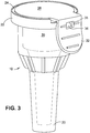
FIG. 3 is another perspective view thereof; and -
FIG. 4 is an elevational view thereof. - As used herein, the "distal" direction is in the direction of the injection site, and the "proximal direction" is the opposite direction. The "axial" direction is along the longitudinal axis of the cannula. The cannula is generally arranged axially in the device. "Radially" is a direction perpendicular to the axial direction; thus, "radially inward" generally means closer to the needle.
- Referring to
FIG. 1 , a pen needleouter cover 10 according to the invention generally comprises adistal cover 20 and aproximal cover 22, both of which are injection molded parts made of plastic. In the illustrated embodiments, thedistal cover 20 is a conventional funnel-shaped, substantially rigid pen needle outer cover that has an openproximal end 14 and narrows in the distal direction to a closedend 21. A commercial pen needle is installed indistal cover 20 through the openproximal end 14. The pen needle has aneedle 31 fixed in a needle-bearinghub 30. The injection end ofneedle 31 is sheathed in a removableinner cover 34.Threads 35 on the inside ofhub 30 are configured to mate with the threads of a medication pen. - An attachment member in the form of an integral, outwardly directed flange 12 extends around substantially the entire open
proximal end 14. In other embodiments, an attachment member on thedistal cover 20 may face inward at the edge of itsproximal opening 14 and engage a mating member onproximal cover 22. Other means for mountingproximal cover 22 to the proximal end ofdistal cover 20 are also within the scope of the invention. - As shown in
FIG. 1 , theproximal cover 22 of the invention is configured with a flexible, resilient,undercut skirt 23 to snap-fit over the flange 12 ofdistal cover 20. The embodiment ofFIGS. 2-4 and others preferably have such a skirt or a similar snap-fit arrangement. In embodiments, the attachment may be further secured by heat-shrinking an additional membrane of cellophane or the like around the outer cover, or an adhesive may be applied to the underside ofproximal cover 22. Other outer cover shapes could also be employed within the scope of the invention.Proximal cover 22 preferably is made of polyethylene, although polypropylene or other plastics known in the art and used in this field may be used in other embodiments. The material may be opaque but preferably is translucent, and more preferably is transparent so that the interior of the outer cover can be viewed easily from the outside.Proximal cover 22 is more rigid than the conventional paper and foil "teardrop" labels that it replaces. Except for its flexible and/or rupturable portions described below,proximal cover 22 may be semirigid or substantially rigid. - While the two
cover portions FIGS. 2-4 , only a central user-separable section 26 ofproximal cover 22 can be pulled back to provide access to the needle-bearing hub inside. In this case, a rupturable, thin-walled border portion ormembrane 24 functions as a tear line and thus defines the user-separable section 26. The thickness of this thin-walled membrane 24 may be selected by persons skilled in the art to achieve the appropriate tear strength, depending on the cover material(s) used. In embodiments, a thickness of 0.004 to 0.012 mm, and preferably 0.004 mm, for the thin-walled portion was found to provide an acceptable tear strength for the preferred injection molded polyethylene material. - If the thin-
walled membrane 24 is continuous - i.e., if it extends uninterrupted from one part of the proximal cover's outer edge to another part of the outer edge, thus defining a closed shape - the user-separable section 26 can be completely removed, leaving the remainder ofproximal cover 22 intact ondistal cover 20. Alternatively and preferably, a living hinge 27 (seeFIG. 2 ) on theproximal cover 22 interrupts the thin-walled border portion 24. Livinghinge 27 keeps the user-separable section 26 partially attached to cover 22 when the user-separable section is separated at the thin-walled border portion 24. In the illustrated, preferred symmetrical arrangement, the livinghinge 27 divides the thin-walled border portion 24 into two equal-length segments. The living hinge is a piece of plastic, co-molded with theproximal cover 22, that bends without breaking to allow the user-separable section 26 to pivot open and provide unobstructed access to the needle-bearinghub 30 through the opening at theproximal end 14 ofdistal cover 20. Livinghinge 27 is thinner than the majority ofproximal cover 22 but thicker than the thin-walled border portion 24. Details of the thickness and width of the living hinge may be left to the discretion of persons skilled in the art, depending on the geometry of the proximal cover and the material used. - In embodiments, the user-
separable section 26 is provided with afinger pull tab 32 at its outer end, preferably opposite livinghinge 27, to facilitate its separation at the thin-walled border portion 24. In embodiments that do not allow for complete removal of the user-separable section 26, a latchingarrangement 33 preferably is provided to permit a user to securely re-cover an opened pen needle with the user-separable section 26 and thus protect against accidental needle sticks. Latchingarrangement 33 includes a first latching portion onproximal cover 22 and a second latching portion onfinger pull tab 32 configured to engage the first latching portion. In the embodiment shown inFIGS. 3 and4 , the first latching portion is a laterally projectingnose 36 on the periphery or sidewall ofproximal cover 22, and the second latching portion is a cooperating facingaperture 38 onpull tab 32 configured to capture thenose 36. Alternatively, the latching mechanism may comprise an inwardly facing nose or rib onpull tab 32 that snaps under the peripheral edge ofproximal cover 22; or it may comprise any other suitable mating features onpull tab 32 andproximal cover 22 that enable re-covering of the pen needle and hub by user-separable section 26. Because rupture of the thin-walled border portion 24 is readily discernable, a user can easily tell that the pen needle cover has been opened previously even though the opening of the distal cover is closed. - Molded indicia may be provided on the plastic
proximal cover 22, viewable from the exterior of the cover. In preferred embodiments, the indicia are visible even after the user-separable section 26 is separated alongtear line 24. For example, the molded indicia may be provided on the outer or inner surface of user-separable section 26 if that section remains connected by a living hinge or other means; or the indicia may be provided on a portion of theproximal cover 22 that remains undisturbed. If theproximal cover 22 is transparent, indicia applied to its inner surface or to the adjacent flange 12 of thedistal cover 20 will be readable through the plastic. The indicia may identify the manufacturer of the part, the lot number, or provide other important and potentially useful information. - The foregoing description of the preferred embodiments is not to be deemed limiting of the invention, which is defined by the appended claims. Persons skilled in the art, relying on the foregoing disclosure, may practice variants of the embodiments described without departing from the scope of the invention claimed. Although described in connection with the delivery of self-administered insulin, pen needles packaged as described herein may be used to deliver other liquid medications. Features described herein in connection with one embodiment may be adapted for use with other embodiments without departing from the scope of the invention.
Claims (11)
- A pen needle outer cover, comprising:a plastic distal cover portion (20) having a closed distal end (21), an opening at a proximal end and an attachment member (24) adjacent the opening (14); anda plastic proximal cover portion (22) engaging the attachment member (24),wherein the proximal cover portion (22) has a rupturable, thin-walled border portion defining a user-separable section (26) of the proximal cover portion (22),characterized in thata first latching portion can be releasably re-engaged with a second latching portion after the user-separable section (26) has been separated at the thin-walled border portion,wherein the user-separable section (26) has a finger pull tab (32) at an outer end thereof, andwherein a sidewall of the distal cover portion (20) includes a first latching portion, and the finger pull tab (32) includes a second latching portion configured to engage the first latching portion.
- The pen needle outer cover according to claim 1, including a living hinge (27) on the proximal cover portion (22) connecting the user-separable section (26) to the proximal cover portion (22) and allowing the user-separable section (26) to pivot when the thin-walled border portion is ruptured.
- The pen needle outer cover according to claim 2, wherein the living hinge (27) divides the thin-walled border portion into two segments.
- The pen needle outer cover according to claim 1, wherein the thin-walled border portion defines a user-separable section (26) that can be removed completely from the outer cover.
- The pen needle outer cover according to claim 4, wherein the thin-walled border portion is continuous, thus defining a closed shape.
- The pen needle outer cover according to any one of the preceding claims, wherein the attachment member (24) includes a flange adjacent the opening (14) of the distal cover portion (20).
- The pen needle outer cover according to any one of the preceding claims, wherein the attachment member (24) includes a flange running substantially around the opening (14) of the distal cover portion (20), and the proximal cover portion (22) is snap-fit over the flange.
- The pen needle outer cover according to any one of the preceding claims, wherein the distal cover portion (20) and the proximal cover portion (22) are made of injection molded polyethylene and the thin-walled border portion has a thickness in the range of 0.004 to 0.012 mm.
- The pen needle outer cover according to claim 1, wherein the first latching portion includes a lateral projection and the second latching portion includes an aperture configured to capture the lateral projection.
- The pen needle outer cover according to any one of the preceding claims, wherein the proximal cover portion is transparent.
- A pen needle assembly, comprising:a hub and a cannula fixed axially to the hub; andthe pen needle outer cover of any one of claims 1-10.
Applications Claiming Priority (2)
| Application Number | Priority Date | Filing Date | Title |
|---|---|---|---|
| US201462009475P | 2014-06-09 | 2014-06-09 | |
| PCT/US2015/034700 WO2015191457A1 (en) | 2014-06-09 | 2015-06-08 | Tamper-evident pen needle outer cover |
Publications (3)
| Publication Number | Publication Date |
|---|---|
| EP3151890A1 EP3151890A1 (en) | 2017-04-12 |
| EP3151890A4 EP3151890A4 (en) | 2018-01-17 |
| EP3151890B1 true EP3151890B1 (en) | 2020-10-28 |
Family
ID=54834150
Family Applications (1)
| Application Number | Title | Priority Date | Filing Date |
|---|---|---|---|
| EP15807352.8A Active EP3151890B1 (en) | 2014-06-09 | 2015-06-08 | Tamper-evident pen needle outer cover |
Country Status (7)
| Country | Link |
|---|---|
| US (2) | US10398828B2 (en) |
| EP (1) | EP3151890B1 (en) |
| JP (1) | JP6707035B2 (en) |
| CN (1) | CN206167538U (en) |
| CA (1) | CA2949386C (en) |
| ES (1) | ES2843949T3 (en) |
| WO (1) | WO2015191457A1 (en) |
Families Citing this family (14)
| Publication number | Priority date | Publication date | Assignee | Title |
|---|---|---|---|---|
| US11007313B2 (en) | 2016-04-28 | 2021-05-18 | Becton, Dickinson And Company | Pen needle magazine |
| WO2017189174A1 (en) * | 2016-04-28 | 2017-11-02 | Becton, Dickinson And Company | Pen needle magazine |
| JP6921117B2 (en) | 2016-04-28 | 2021-08-18 | ベクトン・ディキンソン・アンド・カンパニーBecton, Dickinson And Company | Pen Needle Magazine |
| US11173253B2 (en) | 2016-12-12 | 2021-11-16 | Becton, Dickinson And Company | Packaging for safety needle |
| US11147910B2 (en) | 2016-12-12 | 2021-10-19 | Becton, Dickinson And Company | Packaging for safety needle |
| US11103651B2 (en) | 2016-12-13 | 2021-08-31 | Beckon, Dickinson and Company | Safety needle devices |
| US20180161491A1 (en) * | 2016-12-12 | 2018-06-14 | Becton, Dickinson And Company | Packaging For Safety Needle |
| US10729843B2 (en) | 2016-12-12 | 2020-08-04 | Becton, Dickinson And Company | Dual packaging for fill needle and safety needle |
| US10792439B2 (en) | 2016-12-13 | 2020-10-06 | Becton, Dickinson And Company | Safety needle devices |
| US10589036B2 (en) | 2016-12-13 | 2020-03-17 | Becton, Dickinson And Company | Safety needle device |
| US10661026B2 (en) | 2016-12-13 | 2020-05-26 | Becton, Dickinson And Company | Safety needle device |
| CN107054876A (en) * | 2017-06-03 | 2017-08-18 | 成都五义医疗科技有限公司 | A kind of multi-functional ladder overcoat packed for puncture outfit |
| CA3140289A1 (en) * | 2019-06-20 | 2020-12-24 | Amit Uday Limaye | Pen needle |
| MX2023004818A (en) * | 2020-10-27 | 2023-05-10 | Becton Dickinson Co | Drug delivery system, and barrier apparatus and pull tab therefor. |
Family Cites Families (26)
| Publication number | Priority date | Publication date | Assignee | Title |
|---|---|---|---|---|
| US3860148A (en) * | 1973-04-06 | 1975-01-14 | Sage Products Inc | Liquid container |
| US4623336A (en) * | 1984-05-11 | 1986-11-18 | Pedicano James J | Disposable safety needle sheath |
| US4784296A (en) | 1986-01-03 | 1988-11-15 | Cap Snap Co. | Cap for keg dispenser |
| AU670254B2 (en) * | 1991-12-19 | 1996-07-11 | Needle Technology (Aust) Limited | Needle housing assembly |
| JPH09509087A (en) * | 1994-02-28 | 1997-09-16 | ノボ ノルディスク アクティーゼルスカブ | Needle unit |
| EP0799065B1 (en) * | 1994-07-19 | 2001-11-28 | Novo Nordisk A/S | Needle magazine |
| JP3924986B2 (en) * | 1999-04-23 | 2007-06-06 | 凸版印刷株式会社 | Paper lid |
| EP1138338A1 (en) | 2000-03-20 | 2001-10-04 | Becton Dickinson and Company | Medical safety disposal cap assembly |
| US20020010484A1 (en) * | 2000-07-21 | 2002-01-24 | Miguel Cabada | Microkeratome spring deceleration device |
| US6460712B2 (en) | 2001-02-02 | 2002-10-08 | Seaquist Closures Foreign, Inc. | One-piece tamper-evident closure system with a resealable, hinged lid |
| MY138157A (en) * | 2002-03-07 | 2009-04-30 | Brasilata Embalagens Metalicas | Plastic lid for a can |
| US20050133508A1 (en) * | 2003-12-17 | 2005-06-23 | Landis Russel J. | Tamper evident lid welded to a container |
| US7665605B2 (en) * | 2004-08-14 | 2010-02-23 | Ultimed, Inc. | Sharps container for (I) safe disposal and storage of a single used medical pen needle and/or (II) safe storage and dispensing of a single unused medical pen needle |
| US7631776B2 (en) * | 2005-06-10 | 2009-12-15 | Pwp Industries | Tamper evident container with tear-apart parts |
| US8083089B2 (en) * | 2005-07-13 | 2011-12-27 | Pwp Industries Inc. | Versatile tamper-evident food container |
| US8833589B2 (en) * | 2005-12-21 | 2014-09-16 | Pactiv Packaging Inc. | Enhanced tamper evident bowl with blocked tab |
| US20080097342A1 (en) * | 2006-07-03 | 2008-04-24 | Vadim Alexander Gordin | Cover/sheath for a needle and method of resheathing a used needle |
| US8720727B2 (en) * | 2006-08-14 | 2014-05-13 | Nestech Machine Systems, Inc. | Dual tab lid |
| CA2639323C (en) | 2007-09-07 | 2016-03-15 | Becton, Dickinson And Company | Pen needle assembly outer cover having a breakaway flange |
| US8030919B2 (en) * | 2008-04-18 | 2011-10-04 | Case Western Reserve University | Dark blood balanced steady state free precession imaging |
| US20100084400A1 (en) * | 2008-10-02 | 2010-04-08 | Emplal Embalagens Plasticas Ltda. | Packaging Comprising A Tub And A Lid |
| EP2201976A1 (en) | 2008-12-23 | 2010-06-30 | Sanofi-Aventis Deutschland GmbH | Apparatus for holding a cover of a needle unit and method |
| CA2751622C (en) * | 2009-02-06 | 2018-03-06 | Becton, Dickinson And Company | Disposable pen needle with re-use prevention features |
| US8133200B2 (en) * | 2009-09-18 | 2012-03-13 | Becton, Dickinson And Company | Reversible cap for pen needle outer cover |
| JP2013130694A (en) * | 2011-12-21 | 2013-07-04 | Toppan Printing Co Ltd | Label with tamper-proof function |
| US9359113B2 (en) * | 2014-04-24 | 2016-06-07 | Ya-Chien Chen | Tamper-proof and easy-open sealing type food container |
-
2015
- 2015-06-08 CN CN201590000699.XU patent/CN206167538U/en active Active
- 2015-06-08 ES ES15807352T patent/ES2843949T3/en active Active
- 2015-06-08 EP EP15807352.8A patent/EP3151890B1/en active Active
- 2015-06-08 US US15/317,461 patent/US10398828B2/en active Active
- 2015-06-08 WO PCT/US2015/034700 patent/WO2015191457A1/en active Application Filing
- 2015-06-08 CA CA2949386A patent/CA2949386C/en active Active
- 2015-06-08 JP JP2016572255A patent/JP6707035B2/en active Active
-
2019
- 2019-07-29 US US16/524,839 patent/US10912880B2/en active Active
Non-Patent Citations (1)
| Title |
|---|
| None * |
Also Published As
| Publication number | Publication date |
|---|---|
| EP3151890A4 (en) | 2018-01-17 |
| US10398828B2 (en) | 2019-09-03 |
| EP3151890A1 (en) | 2017-04-12 |
| US10912880B2 (en) | 2021-02-09 |
| CA2949386A1 (en) | 2015-12-17 |
| JP2017517331A (en) | 2017-06-29 |
| WO2015191457A1 (en) | 2015-12-17 |
| US20170106136A1 (en) | 2017-04-20 |
| CA2949386C (en) | 2023-01-10 |
| JP6707035B2 (en) | 2020-06-10 |
| US20190351129A1 (en) | 2019-11-21 |
| ES2843949T3 (en) | 2021-07-21 |
| CN206167538U (en) | 2017-05-17 |
Similar Documents
| Publication | Publication Date | Title |
|---|---|---|
| US10912880B2 (en) | Tamper-evident pen needle outer cover | |
| EP3038941B1 (en) | Cap for a container | |
| JP4024357B2 (en) | Syringe | |
| JPS6055380B2 (en) | Flexible sealing cover for resealing the mouth of a drug container and its assembly method | |
| EP3129082B1 (en) | Hinged cap needle assemblies and related methods | |
| JPS62287859A (en) | Sealing body displaying unsealing trace | |
| EP3381492B1 (en) | Syringe tip cap assembly, syringe comprising such a syringe tip cap and method of sealing a syringe barrel | |
| US8978890B2 (en) | Security label for protecting medicaments contained in an individual packaging | |
| US20230298486A1 (en) | Adhesive label for a multi-part container, system and method for applying an adhesive label to a multi-part container | |
| WO2015101541A1 (en) | Tamper-evident cap assembly for a container | |
| JP6682140B2 (en) | Hinge cap with tamper-proof mechanism | |
| US20220241516A1 (en) | Pen needle | |
| US20220081176A1 (en) | Labelling arrangement for a multi-part container, system and method for applying a labelling arrangement to a multi-part container | |
| JP5116279B2 (en) | Resin cap and container with resin cap using the same | |
| JP7333214B2 (en) | container with label | |
| JP6798842B2 (en) | Labeled container cap | |
| EP1032351A1 (en) | A method, a combination and a container for dispensing medicinal tablets | |
| SK17922000A3 (en) | Pre-filled container | |
| CN220683386U (en) | Medicine bottle cap and medicine bottle | |
| JP4173302B2 (en) | Medical needle | |
| JP2736218B2 (en) | Chemical bottle closing device | |
| WO2019189278A1 (en) | Syringe barrel assembly, package, and pre-filled syringe | |
| FI3737614T3 (en) | Container having a sealing cap and a tear-off ring | |
| WO2022172102A1 (en) | Rubber sealing element for a plastic closing device for parenterally administrable drugs | |
| JP2003054610A (en) | Tamper-evident hinge cap |
Legal Events
| Date | Code | Title | Description |
|---|---|---|---|
| STAA | Information on the status of an ep patent application or granted ep patent |
Free format text: STATUS: THE INTERNATIONAL PUBLICATION HAS BEEN MADE |
|
| PUAI | Public reference made under article 153(3) epc to a published international application that has entered the european phase |
Free format text: ORIGINAL CODE: 0009012 |
|
| STAA | Information on the status of an ep patent application or granted ep patent |
Free format text: STATUS: REQUEST FOR EXAMINATION WAS MADE |
|
| 17P | Request for examination filed |
Effective date: 20170103 |
|
| AK | Designated contracting states |
Kind code of ref document: A1 Designated state(s): AL AT BE BG CH CY CZ DE DK EE ES FI FR GB GR HR HU IE IS IT LI LT LU LV MC MK MT NL NO PL PT RO RS SE SI SK SM TR |
|
| AX | Request for extension of the european patent |
Extension state: BA ME |
|
| RIN1 | Information on inventor provided before grant (corrected) |
Inventor name: DIBIASI, MICHAEL |
|
| DAV | Request for validation of the european patent (deleted) | ||
| DAX | Request for extension of the european patent (deleted) | ||
| A4 | Supplementary search report drawn up and despatched |
Effective date: 20171219 |
|
| RIC1 | Information provided on ipc code assigned before grant |
Ipc: A61M 5/00 20060101ALI20171213BHEP Ipc: A61M 5/50 20060101ALI20171213BHEP Ipc: B65D 43/22 20060101ALI20171213BHEP Ipc: B65D 43/16 20060101ALI20171213BHEP Ipc: A61M 5/32 20060101AFI20171213BHEP |
|
| STAA | Information on the status of an ep patent application or granted ep patent |
Free format text: STATUS: EXAMINATION IS IN PROGRESS |
|
| 17Q | First examination report despatched |
Effective date: 20190712 |
|
| GRAP | Despatch of communication of intention to grant a patent |
Free format text: ORIGINAL CODE: EPIDOSNIGR1 |
|
| STAA | Information on the status of an ep patent application or granted ep patent |
Free format text: STATUS: GRANT OF PATENT IS INTENDED |
|
| INTG | Intention to grant announced |
Effective date: 20200515 |
|
| GRAS | Grant fee paid |
Free format text: ORIGINAL CODE: EPIDOSNIGR3 |
|
| GRAA | (expected) grant |
Free format text: ORIGINAL CODE: 0009210 |
|
| STAA | Information on the status of an ep patent application or granted ep patent |
Free format text: STATUS: THE PATENT HAS BEEN GRANTED |
|
| AK | Designated contracting states |
Kind code of ref document: B1 Designated state(s): AL AT BE BG CH CY CZ DE DK EE ES FI FR GB GR HR HU IE IS IT LI LT LU LV MC MK MT NL NO PL PT RO RS SE SI SK SM TR |
|
| REG | Reference to a national code |
Ref country code: GB Ref legal event code: FG4D |
|
| REG | Reference to a national code |
Ref country code: CH Ref legal event code: EP |
|
| REG | Reference to a national code |
Ref country code: DE Ref legal event code: R096 Ref document number: 602015061226 Country of ref document: DE |
|
| REG | Reference to a national code |
Ref country code: AT Ref legal event code: REF Ref document number: 1327574 Country of ref document: AT Kind code of ref document: T Effective date: 20201115 |
|
| REG | Reference to a national code |
Ref country code: IE Ref legal event code: FG4D |
|
| REG | Reference to a national code |
Ref country code: AT Ref legal event code: MK05 Ref document number: 1327574 Country of ref document: AT Kind code of ref document: T Effective date: 20201028 |
|
| REG | Reference to a national code |
Ref country code: NL Ref legal event code: MP Effective date: 20201028 |
|
| PG25 | Lapsed in a contracting state [announced via postgrant information from national office to epo] |
Ref country code: GR Free format text: LAPSE BECAUSE OF FAILURE TO SUBMIT A TRANSLATION OF THE DESCRIPTION OR TO PAY THE FEE WITHIN THE PRESCRIBED TIME-LIMIT Effective date: 20210129 Ref country code: NO Free format text: LAPSE BECAUSE OF FAILURE TO SUBMIT A TRANSLATION OF THE DESCRIPTION OR TO PAY THE FEE WITHIN THE PRESCRIBED TIME-LIMIT Effective date: 20210128 Ref country code: NL Free format text: LAPSE BECAUSE OF FAILURE TO SUBMIT A TRANSLATION OF THE DESCRIPTION OR TO PAY THE FEE WITHIN THE PRESCRIBED TIME-LIMIT Effective date: 20201028 Ref country code: FI Free format text: LAPSE BECAUSE OF FAILURE TO SUBMIT A TRANSLATION OF THE DESCRIPTION OR TO PAY THE FEE WITHIN THE PRESCRIBED TIME-LIMIT Effective date: 20201028 Ref country code: RS Free format text: LAPSE BECAUSE OF FAILURE TO SUBMIT A TRANSLATION OF THE DESCRIPTION OR TO PAY THE FEE WITHIN THE PRESCRIBED TIME-LIMIT Effective date: 20201028 Ref country code: PT Free format text: LAPSE BECAUSE OF FAILURE TO SUBMIT A TRANSLATION OF THE DESCRIPTION OR TO PAY THE FEE WITHIN THE PRESCRIBED TIME-LIMIT Effective date: 20210301 |
|
| REG | Reference to a national code |
Ref country code: LT Ref legal event code: MG4D |
|
| PG25 | Lapsed in a contracting state [announced via postgrant information from national office to epo] |
Ref country code: AT Free format text: LAPSE BECAUSE OF FAILURE TO SUBMIT A TRANSLATION OF THE DESCRIPTION OR TO PAY THE FEE WITHIN THE PRESCRIBED TIME-LIMIT Effective date: 20201028 Ref country code: BG Free format text: LAPSE BECAUSE OF FAILURE TO SUBMIT A TRANSLATION OF THE DESCRIPTION OR TO PAY THE FEE WITHIN THE PRESCRIBED TIME-LIMIT Effective date: 20210128 Ref country code: PL Free format text: LAPSE BECAUSE OF FAILURE TO SUBMIT A TRANSLATION OF THE DESCRIPTION OR TO PAY THE FEE WITHIN THE PRESCRIBED TIME-LIMIT Effective date: 20201028 Ref country code: SE Free format text: LAPSE BECAUSE OF FAILURE TO SUBMIT A TRANSLATION OF THE DESCRIPTION OR TO PAY THE FEE WITHIN THE PRESCRIBED TIME-LIMIT Effective date: 20201028 Ref country code: IS Free format text: LAPSE BECAUSE OF FAILURE TO SUBMIT A TRANSLATION OF THE DESCRIPTION OR TO PAY THE FEE WITHIN THE PRESCRIBED TIME-LIMIT Effective date: 20210228 Ref country code: LV Free format text: LAPSE BECAUSE OF FAILURE TO SUBMIT A TRANSLATION OF THE DESCRIPTION OR TO PAY THE FEE WITHIN THE PRESCRIBED TIME-LIMIT Effective date: 20201028 |
|
| PG25 | Lapsed in a contracting state [announced via postgrant information from national office to epo] |
Ref country code: HR Free format text: LAPSE BECAUSE OF FAILURE TO SUBMIT A TRANSLATION OF THE DESCRIPTION OR TO PAY THE FEE WITHIN THE PRESCRIBED TIME-LIMIT Effective date: 20201028 |
|
| REG | Reference to a national code |
Ref country code: ES Ref legal event code: FG2A Ref document number: 2843949 Country of ref document: ES Kind code of ref document: T3 Effective date: 20210721 |
|
| REG | Reference to a national code |
Ref country code: DE Ref legal event code: R097 Ref document number: 602015061226 Country of ref document: DE |
|
| PG25 | Lapsed in a contracting state [announced via postgrant information from national office to epo] |
Ref country code: SM Free format text: LAPSE BECAUSE OF FAILURE TO SUBMIT A TRANSLATION OF THE DESCRIPTION OR TO PAY THE FEE WITHIN THE PRESCRIBED TIME-LIMIT Effective date: 20201028 Ref country code: EE Free format text: LAPSE BECAUSE OF FAILURE TO SUBMIT A TRANSLATION OF THE DESCRIPTION OR TO PAY THE FEE WITHIN THE PRESCRIBED TIME-LIMIT Effective date: 20201028 Ref country code: CZ Free format text: LAPSE BECAUSE OF FAILURE TO SUBMIT A TRANSLATION OF THE DESCRIPTION OR TO PAY THE FEE WITHIN THE PRESCRIBED TIME-LIMIT Effective date: 20201028 Ref country code: RO Free format text: LAPSE BECAUSE OF FAILURE TO SUBMIT A TRANSLATION OF THE DESCRIPTION OR TO PAY THE FEE WITHIN THE PRESCRIBED TIME-LIMIT Effective date: 20201028 Ref country code: SK Free format text: LAPSE BECAUSE OF FAILURE TO SUBMIT A TRANSLATION OF THE DESCRIPTION OR TO PAY THE FEE WITHIN THE PRESCRIBED TIME-LIMIT Effective date: 20201028 Ref country code: LT Free format text: LAPSE BECAUSE OF FAILURE TO SUBMIT A TRANSLATION OF THE DESCRIPTION OR TO PAY THE FEE WITHIN THE PRESCRIBED TIME-LIMIT Effective date: 20201028 |
|
| PG25 | Lapsed in a contracting state [announced via postgrant information from national office to epo] |
Ref country code: DK Free format text: LAPSE BECAUSE OF FAILURE TO SUBMIT A TRANSLATION OF THE DESCRIPTION OR TO PAY THE FEE WITHIN THE PRESCRIBED TIME-LIMIT Effective date: 20201028 |
|
| PLBE | No opposition filed within time limit |
Free format text: ORIGINAL CODE: 0009261 |
|
| STAA | Information on the status of an ep patent application or granted ep patent |
Free format text: STATUS: NO OPPOSITION FILED WITHIN TIME LIMIT |
|
| 26N | No opposition filed |
Effective date: 20210729 |
|
| PG25 | Lapsed in a contracting state [announced via postgrant information from national office to epo] |
Ref country code: AL Free format text: LAPSE BECAUSE OF FAILURE TO SUBMIT A TRANSLATION OF THE DESCRIPTION OR TO PAY THE FEE WITHIN THE PRESCRIBED TIME-LIMIT Effective date: 20201028 |
|
| PG25 | Lapsed in a contracting state [announced via postgrant information from national office to epo] |
Ref country code: SI Free format text: LAPSE BECAUSE OF FAILURE TO SUBMIT A TRANSLATION OF THE DESCRIPTION OR TO PAY THE FEE WITHIN THE PRESCRIBED TIME-LIMIT Effective date: 20201028 |
|
| PG25 | Lapsed in a contracting state [announced via postgrant information from national office to epo] |
Ref country code: MC Free format text: LAPSE BECAUSE OF FAILURE TO SUBMIT A TRANSLATION OF THE DESCRIPTION OR TO PAY THE FEE WITHIN THE PRESCRIBED TIME-LIMIT Effective date: 20201028 |
|
| REG | Reference to a national code |
Ref country code: CH Ref legal event code: PL |
|
| REG | Reference to a national code |
Ref country code: BE Ref legal event code: MM Effective date: 20210630 |
|
| PG25 | Lapsed in a contracting state [announced via postgrant information from national office to epo] |
Ref country code: LU Free format text: LAPSE BECAUSE OF NON-PAYMENT OF DUE FEES Effective date: 20210608 |
|
| PG25 | Lapsed in a contracting state [announced via postgrant information from national office to epo] |
Ref country code: LI Free format text: LAPSE BECAUSE OF NON-PAYMENT OF DUE FEES Effective date: 20210630 Ref country code: CH Free format text: LAPSE BECAUSE OF NON-PAYMENT OF DUE FEES Effective date: 20210630 |
|
| PG25 | Lapsed in a contracting state [announced via postgrant information from national office to epo] |
Ref country code: IS Free format text: LAPSE BECAUSE OF FAILURE TO SUBMIT A TRANSLATION OF THE DESCRIPTION OR TO PAY THE FEE WITHIN THE PRESCRIBED TIME-LIMIT Effective date: 20210228 |
|
| PG25 | Lapsed in a contracting state [announced via postgrant information from national office to epo] |
Ref country code: BE Free format text: LAPSE BECAUSE OF NON-PAYMENT OF DUE FEES Effective date: 20210630 |
|
| PG25 | Lapsed in a contracting state [announced via postgrant information from national office to epo] |
Ref country code: HU Free format text: LAPSE BECAUSE OF FAILURE TO SUBMIT A TRANSLATION OF THE DESCRIPTION OR TO PAY THE FEE WITHIN THE PRESCRIBED TIME-LIMIT; INVALID AB INITIO Effective date: 20150608 |
|
| P01 | Opt-out of the competence of the unified patent court (upc) registered |
Effective date: 20230427 |
|
| PG25 | Lapsed in a contracting state [announced via postgrant information from national office to epo] |
Ref country code: CY Free format text: LAPSE BECAUSE OF FAILURE TO SUBMIT A TRANSLATION OF THE DESCRIPTION OR TO PAY THE FEE WITHIN THE PRESCRIBED TIME-LIMIT Effective date: 20201028 |
|
| PGFP | Annual fee paid to national office [announced via postgrant information from national office to epo] |
Ref country code: IT Payment date: 20230523 Year of fee payment: 9 Ref country code: IE Payment date: 20230525 Year of fee payment: 9 Ref country code: FR Payment date: 20230523 Year of fee payment: 9 Ref country code: DE Payment date: 20230523 Year of fee payment: 9 |
|
| PGFP | Annual fee paid to national office [announced via postgrant information from national office to epo] |
Ref country code: GB Payment date: 20230523 Year of fee payment: 9 Ref country code: ES Payment date: 20230703 Year of fee payment: 9 |