EP3151587A1 - Connection confirmation system, connection confirmation program, connection confirmation method, and connection detection device - Google Patents
Connection confirmation system, connection confirmation program, connection confirmation method, and connection detection device Download PDFInfo
- Publication number
- EP3151587A1 EP3151587A1 EP15799806.3A EP15799806A EP3151587A1 EP 3151587 A1 EP3151587 A1 EP 3151587A1 EP 15799806 A EP15799806 A EP 15799806A EP 3151587 A1 EP3151587 A1 EP 3151587A1
- Authority
- EP
- European Patent Office
- Prior art keywords
- connection
- connection mode
- detection apparatus
- speaker
- unit
- Prior art date
- Legal status (The legal status is an assumption and is not a legal conclusion. Google has not performed a legal analysis and makes no representation as to the accuracy of the status listed.)
- Granted
Links
Images








Classifications
-
- G—PHYSICS
- G06—COMPUTING OR CALCULATING; COUNTING
- G06F—ELECTRIC DIGITAL DATA PROCESSING
- G06F11/00—Error detection; Error correction; Monitoring
- G06F11/30—Monitoring
- G06F11/3051—Monitoring arrangements for monitoring the configuration of the computing system or of the computing system component, e.g. monitoring the presence of processing resources, peripherals, I/O links, software programs
-
- G—PHYSICS
- G06—COMPUTING OR CALCULATING; COUNTING
- G06F—ELECTRIC DIGITAL DATA PROCESSING
- G06F11/00—Error detection; Error correction; Monitoring
- G06F11/30—Monitoring
- G06F11/3003—Monitoring arrangements specially adapted to the computing system or computing system component being monitored
- G06F11/3041—Monitoring arrangements specially adapted to the computing system or computing system component being monitored where the computing system component is an input/output interface
-
- G—PHYSICS
- G06—COMPUTING OR CALCULATING; COUNTING
- G06F—ELECTRIC DIGITAL DATA PROCESSING
- G06F13/00—Interconnection of, or transfer of information or other signals between, memories, input/output devices or central processing units
- G06F13/10—Program control for peripheral devices
- G06F13/102—Program control for peripheral devices where the program performs an interfacing function, e.g. device driver
-
- H—ELECTRICITY
- H04—ELECTRIC COMMUNICATION TECHNIQUE
- H04R—LOUDSPEAKERS, MICROPHONES, GRAMOPHONE PICK-UPS OR LIKE ACOUSTIC ELECTROMECHANICAL TRANSDUCERS; ELECTRIC HEARING AIDS; PUBLIC ADDRESS SYSTEMS
- H04R29/00—Monitoring arrangements; Testing arrangements
- H04R29/001—Monitoring arrangements; Testing arrangements for loudspeakers
-
- H—ELECTRICITY
- H04—ELECTRIC COMMUNICATION TECHNIQUE
- H04S—STEREOPHONIC SYSTEMS
- H04S5/00—Pseudo-stereo systems, e.g. in which additional channel signals are derived from monophonic signals by means of phase shifting, time delay or reverberation
- H04S5/02—Pseudo-stereo systems, e.g. in which additional channel signals are derived from monophonic signals by means of phase shifting, time delay or reverberation of the pseudo four-channel type, e.g. in which rear channel signals are derived from two-channel stereo signals
Definitions
- the present invention relates to a connection confirmation system, a connection confirmation program, a connection confirmation method, and a connection detection apparatus.
- a sound processing apparatus described in Patent Literature 1 is configured to detect a speaker actually connected to the own apparatus by causing the speaker to output a test sound and by picking up the output test sound by using a microphone.
- the sound processing apparatus described in Patent Literature 1 ( JP 2006-174094 A ) is configured to automatically correct a connection setting of the own apparatus in accordance with a connection mode of devices actually connected to the own apparatus. More specifically, the sound processing apparatus described in Patent Literature 1 is configured to automatically correct various settings such that, when only front left/right (L/R) speakers and surround L/R speakers are connected to the own apparatus, for example, those front L/R speakers and surround L/R speakers are detected, to thereby invalidate the setting of unconnected speakers (e.g., a center (C) channel speaker).
- L/R left/right
- C center
- Patent Literature 1 the sound processing apparatus described in Patent Literature 1 is configured to automatically correct the setting based only on the actual connection mode, and hence there are cases in which the corrected connection mode does not match the connection mode desired by a user.
- the user may want to generate a sound field by using 7-channel surround sound (front left (FL), front right (FR), center (C), surround left (SL), surround right (SR), surround back left (SBL), and surround back right (SBR) channels) including surround back speakers.
- 7-channel surround sound front left (FL), front right (FR), center (C), surround left (SL), surround right (SR), surround back left (SBL), and surround back right (SBR) channels
- the sound processing apparatus detects that presence speakers are connected, and hence generates the sound field by using 7-channel surround sound (FL, FR, C, SL, SR, PL, and PR channels) including presence speakers, which does not conform to the setting intended by the user.
- the sound processing apparatus automatically generates the sound field based on a connection setting including presence speakers. Therefore, such a sound processing apparatus outputs a sound from each detected speaker, but the sounds set to be output from the setting position of the presence speakers are output from the setting position of the surround back speakers. As a result, unless the user notices a difference between a desired connection mode and the actual connection mode, the user cannot obtain the desired sound effect.
- connection confirmation system a connection confirmation program, a connection confirmation method, and a connection detection apparatus, which are capable of detecting and informing a user of a difference between a connection mode of a connected device and a connection mode desired by the user.
- a connection confirmation system including: a connection detection apparatus; and an information processing apparatus, the connection detection apparatus and the information processing apparatus being configured to communicate to and from each other, the information processing apparatus including a receiving unit configured to receive an input of a setting relating to a connection mode of a device to be connected to the connection detection apparatus, the connection detection apparatus including a detection unit configured to detect a connection mode of an actually-connected device, the connection detection apparatus or the information processing apparatus including a determination unit configured to determine a difference between the actual connection mode detected by the detection unit and the connection mode indicated by the setting received by the receiving unit, the information processing apparatus including a display unit configured to perform a display based on a determination result of the determination unit.
- connection confirmation program which is executed in an information processing apparatus, the connection confirmation program being configured to cause the information processing apparatus to execute: a reception step of receiving an input of a setting relating to a connection mode of a device to be connected to a connection detection apparatus; an acquisition step of acquiring, by the connection detection apparatus, a detection result obtained by detecting a connection mode of a device actually connected to the own connection detection apparatus; a determination step of determining a difference between the connection mode indicated by the setting received in the reception step and the actual connection mode acquired in the acquisition step; and a display step of performing a display based on a determination result of the determination step.
- connection confirmation method which is executed by using a connection detection apparatus and an information processing apparatus, the connection confirmation method including: a reception step of receiving in the information processing apparatus an input of a setting relating to a connection mode of a device to be connected to the connection detection apparatus; a detection step of detecting a connection mode of a device actually connected to the connection detection apparatus; a determination step of determining a difference between the connection mode indicated by the setting received in the reception step and the actual connection mode acquired in the detection step; and a display step of performing a display based on a determination result of the determination step.
- a connection detection apparatus including: an acquisition unit configured to acquire a setting relating to a connection mode of a device to be connected to a sound processing apparatus; a detection unit configured to detect a connection mode of a device actually connected to the sound processing apparatus; and a determination unit configured to determine a difference between the actual connection mode detected by the detection unit and the connection mode indicated by the setting acquired by the acquisition unit.
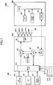
- FIG. 1 is a block diagram for illustrating a portion of a configuration of the connection confirmation system 900.
- FIG. 2 is a function block diagram of an AV receiver 100 and a portable terminal 400.
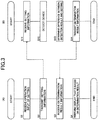
- FIG. 3 (A) is a flowchart for illustrating operation of the portable terminal 400, and
- FIG. 3(B) is a flowchart for illustrating operation of the AV receiver 100.
- connection confirmation system 900 the user performs on a portable terminal 400 an operation input of a setting regarding a connection mode of a device to be connected to an audiovisual (AV) receiver 100.
- the AV receiver 100 is configured to determine a difference between an actual connection mode determined by detecting the devices that are actually connected to the own receiver and the connection mode set by the user.
- the portable terminal 400 is configured to perform a display that is based on the determination result.
- the connection confirmation system 900 according to the first embodiment allows the user to confirm whether or not there is an error in the actual connection, and to set the connection mode of the AV receiver 100 to the connection mode that is desired by the user.
- the connection confirmation system 900 includes the AV receiver 100, a plurality of content reproduction devices 200, a plurality of speakers 300, and the portable terminal 400.
- the AV receiver 100 corresponds to the connection detection apparatus according to the present invention.
- transmission and reception of signals and information via physical cables and internal wiring are represented as the solid lines, and transmission and reception of information by wireless communication are represented as the dotted lines.
- the AV receiver 100 includes an input unit 101, a digital signal processor (DSP) 102, a central processing unit (CPU) 103, a memory 104, an output unit 105, and a radio frequency integrated circuit (RFIC) 106.
- DSP digital signal processor
- CPU central processing unit
- RFIC radio frequency integrated circuit
- the input unit 101 is configured to receive content data from each content reproduction device 200, and to output to the DSP 102 an audio signal extracted from the content data.
- a sound pickup signal from a microphone 107 is input to the input unit 101.
- a Blu-ray Disc (registered trademark) (BD) player 201, a personal computer (PC) 202, and a video camera 203 are connected to the input unit 101 of the AV receiver 100.
- Each content reproduction device 200 is connected to a high-definitionmultimedia interface (HDMI) (registered trademark) connector of the AV receiver 100 via an HDMI cable.
- HDMI high-definitionmultimedia interface
- the content reproduction devices 200 are not limited to being connected to the input unit 101 by an HDMI cable.
- the content reproduction devices 200 may be connected to the input unit 101 by another physical cable, such as a digital optical cable or an analog cable.
- the content reproduction devices 200 are also not limited to being connected to the input unit 101 by a physical cable.
- the content reproduction devices 200 may be connected to the input unit 101 by wireless communication for transmitting audio signals.
- wireless communication wireless local area network (LAN) communication and Bluetooth (registered trademark) communication may be employed.
- a program is stored in the memory 104.
- the program is read and executed by the CPU 103.
- the CPU 103 is configured to control the input unit 101, the DSP 102, the output unit 105, and the RFIC 106 by reading and executing the program.
- the output unit 105 is configured to amplify each input audio signal, and to output the amplified audio signals to the plurality of speakers 300 (speaker 300FL, speaker 300SL, speaker 300C, speaker 300SR, and speaker 300FR).
- each speaker 300 is connected to a speaker connector of the AV receiver 100 via a speaker cable.
- a plurality of speakers supporting 7.1 multi-channel surround sound may be connected to the output unit 105.
- the connection between each of the plurality of speakers 300 and the output unit 105 is not limited to a physical speaker cable.
- the plurality of speakers 300 and the output unit 105 may be connected by wireless communication (e. g. , Bluetooth communication).
- the RFIC 106 is configured to transmit and receive various information to and from the portable terminal 400 under the control of the CPU 103 by using a wireless communication antenna (not shown) .
- the DSP 102 is configured to perform, under the control of the CPU 103, predetermined processing (e.g., volume control, equalizer processing, etc.) on each audio signal input from the input unit 101.
- predetermined processing e.g., volume control, equalizer processing, etc.
- the user performs settings relating to those processes by using operation buttons (e.g. , volume change knob (not shown), frequency change knob (not shown), etc.) on the AV receiver 100.
- operation buttons on the AV receiver 100 are specialized for sound processing.
- the portable terminal 400 includes a CPU 401, a liquid crystal display (LCD) 402, a touch panel 403, and an RFIC 404. Each of those parts is connected to a shared bus.
- the CPU 401 is configured to control the LCD 402, the touch panel 403, and the RFIC 404 in an integrated manner.
- the RFIC 404 is configured to transmit and receive various information to and from the RFIC 106 of the AV receiver 100 under the control of the CPU 401 by using a wireless communication antenna (not shown).
- the LCD 4 02 and the touch panel 403 are arranged in an overlapping manner.
- the CPU 401 is configured to change display content of the LCD 402 based on touch operations by the user received through the touch panel 403.
- the portable terminal 400 is configured to display a graphical user interface (GUI) based on such processing.
- GUI graphical user interface
- the portable terminal 400 is configured to display, when a setting start operation input is received by the touch panel 403, a setting guidance message and a software keyboard on the LCD 402, and to receive key input operations relating to the setting by the touch panel 403. In this manner, the portable terminal 400 is displaying the GUI, and hence the user can easily input operations relating to the setting.
- the user performs on the portable terminal 400 a setting relating to the connection mode of each device connected to the input unit 101 and the output unit 105 (plurality of content reproduction devices 200 and plurality of speakers 300) of the AV receiver 100.
- the setting relating to the connection mode includes, for example, a presence of a connection of the speaker 300 to each channel, a speaker system configuration (e.g. 2-channel and 5-channel), a presence of a connection of each content reproduction device 200, a connection connector number of each content reproduction device 200, a type of each content reproduction device 200 (device type, such as player, PC, or video camera), the manufacturer of each content reproduction device 200, and a model name of each content reproduction device 200 (player model name, PC model name, and video camera model name).
- the AV receiver 100 is configured to implement each function of a sound pickup unit 11, a detection unit 12, a determination unit 13, and a communication unit 14.
- the portable terminal 400 is configured to implement each function of a communication unit 41, a control unit 42, an operation input unit 43, and a display unit 44.
- transmission and reception of information are represented as the solid lines, and transmission and reception of audio signals are represented as the dotted lines.
- transmission and reception of information between the AV receiver 100 and the portable terminal 400 are performed by wireless communication.
- the sound pickup unit 11, the detection unit 12, and the determination unit 13 are implemented by the input unit 101, the output unit 105, the CPU 103, and the DSP 102.
- the sound pickup unit 11 is configured to output an audio signal of a test sound to each channel.
- a sound pickup signal from the microphone 107 is input to the sound pickup unit 11.
- the sound pickup unit 11 is configured to output, as a sound pickup result, a plurality of sound pickup signals corresponding to a plurality of channels to the detection unit 12.
- the detection unit 12 is configured to detect whether or not the speaker 300 is connected to each channel based on the sound pickup result from the sound pickup unit 11. More specifically, when a level of the sound pickup signal for each channel is equal to or more than a predetermined threshold, the detection unit 12 detects that any one of the speakers 300 is connected to that channel.
- the detection unit 12 is configured to output information indicating whether or not the speaker 300 is connected to each channel as a detection result to the determination unit 13. This detection result corresponds to the actual connection mode of the plurality of speakers 300 connected to the AV receiver 100.
- the detection unit 12 is also configured to detect whether or not any one of the content reproduction devices 200 is connected to each HDMI connector of the input unit 101. More specifically, the detection unit 12 transmits a detection signal conforming to an HDMI-Consumer Electronics Control (CEC) format from the HDMI connectors of the input unit 101. A detection result signal conforming to the HDMI-CEC format is input to the detection unit 12. The detection result signal includes, for example, information on the type and model name of the content reproduction device 200. The detection unit 12 is also configured to output the detection result indicated by the detection result signal to the determination unit 13. The detection result signal corresponds to the actual connection mode of the plurality of content reproduction devices 200 connected to the AV receiver 100.
- HDMI-Consumer Electronics Control CEC
- a detection result signal conforming to the HDMI-CEC format is input to the detection unit 12.
- the detection result signal includes, for example, information on the type and model name of the content reproduction device 200.
- the detection unit 12 is also configured to output the detection result indicated by the detection result signal to the determination unit 13.
- the determination unit 13 is configured to determine a difference between the actual connection mode indicated by the detection result output by the detection unit 12 and the connection mode indicated by setting information acquired from the portable terminal 400.
- the setting information from the portable terminal 400 is input from the communication unit 14.
- the determination unit 13 is configured to output the determination result of the difference in connection modes to the communication unit 14.
- the determination result includes information indicating whether or not there is a difference in, for example, the presence of a connection of the speaker 300 to each channel, the speaker system configuration, and the presence of a connection of the content reproduction device 200 to each HDMI connector.
- the determination result also includes information indicating whether or not there is a difference in the connection connector number, the type, the manufacturer, the model name, etc., of each content reproduction device 200.
- the communication unit 14 is configured to transmit the determination result from the determination unit 13 to the communication unit 41 of the portable terminal 400.
- the communication unit 14 is also configured to receive setting information from the communication unit 41 of the portable terminal 400.
- the control unit 42 of the portable terminal 400 is configured to transmit, when the setting information on the connection mode of the devices (plurality of content reproduction devices 200 and plurality of speakers 300) connected to the input unit 101 and the output unit 105 of the AV receiver 100 is acquired from the operation input unit 43, the acquired setting information to the communication unit 14 of the AV receiver 100 via the communication unit 41.
- the control unit 42 is configured to cause the display unit 44 to perform, when the determination result of the determination unit 13 of the AV receiver 100 is acquired via the communication unit 41, a display that is based on that determination result.
- the portable terminal 400 may include, in the own terminal, the program for implementing the display that is based on the operation input of the setting and the determination result.
- the AV receiver 100 may be configured to acquire the operation input of the setting by causing, when the portable terminal 400 accesses the own terminal via a general-purpose WEB browser, the portable terminal 400 to execute a WEB application for inputting the setting.
- the AV receiver 100 may also be configured to cause the WEB application operated by the portable terminal 400 to execute a display that is based on a difference between the connection mode indicated by the setting information acquired via the WEB application and the detected actual connection mode.
- the various function units of the AV receiver 100 and the portable terminal 400 are configured to operate in the following manner in order to perform connection confirmation processing that allows the user to confirm the connectionmode of the devices connected to the AV receiver 100.
- the control unit 42 causes the communication unit 41 to transmit that setting information (S3).
- the communication unit 14 of the AV receiver 100 receives the setting information from the communication unit 41 (S11).
- the AV receiver 100 detects the presence of a connection for each of the plurality of speakers 300 (S12). More specifically, the sound pickup unit 11 outputs the audio signal of the test sound to each channel. When any one of the speakers 300 is connected to a corresponding channel, the sound pickup unit 11 picks up the test sound output by that speaker 300. When the level of each sound pickup signal is equal to or more than a predetermined threshold, the detection unit 12 detects that any one of the speakers 300 is connected to the channel corresponding to that sound pickup signal.
- the detection unit 12 also detects each content reproduction device 200 connected in accordance with the HDMI standard. More specifically, the detection unit 12 outputs a detection signal conforming to the HDMI-CEC format from each HDMI connector. When any one of the content reproduction devices 200 is connected to an HDMI connector, and there is a response to the detection signal in the HDMI-CEC format, the detection unit 12 receives a detection result signal in the HDMI-CEC format from the content reproduction device 200. This enables the detection unit 12 to detect the connection mode, such as the presence of a connection of the content reproduction device 200 to each HDMI connector of the input unit 101, and the type, model name, etc., of the content reproduction devices 200 connected to the HDMI connectors of the input unit 101.
- the AV receiver 100 may perform the processing of Step S12 before the processing of Step S11.
- the determination unit 13 determines a difference between the actual connection mode indicated by the detection result acquired in Step S12 and the connection mode indicated by the setting information received in Step S11 (S13). Then, the communication unit 14 transmits information on the determination result of the determination unit 13 to the communication unit 41 (S14). The communication unit 41 of the portable terminal 400 receives the information on the determination result transmitted from the communication unit 14 (S3). Then, the control unit 42 causes the display unit 44 to perform a display that is based on the determination result (S4).
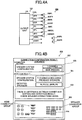
- FIG. 4A is a diagram for illustrating a connection between the output unit and each speaker in order to illustrate a connection example by the user.
- FIG. 4B is a diagram for illustrating a display example of the portable terminal.
- the user performs a connection setting in order to listen to seven channels (FL, FR, C, SL, SR, SBL, and SBR), including surround back speakers (S1).
- the speaker 300FL, the speaker 300FR, the speaker 300SL, the speaker 300SR, and the speaker 300C are each connected to a speaker connector 15 for the corresponding channel, but the speaker 300SBL for surround back is connected to a speaker connector 15PL for a presence speaker, and the speaker 300SBR for surround back is connected to a speaker connector 15PR for a presence speaker.
- the speaker 300PL and the speaker 300PR, which are presence speakers, are not connected to any of the speaker connectors 15.
- the connection example illustrated in FIG. 4A is an example in which the user has made an error in the connections of the surround back speakers.
- the detection unit 12 detects that the speakers 300 are connected to the FL, FR, SL, SR, C, PL, and PR channels (S2).
- the detection unit 12 considers and detects the speakers 300 connected to the FL, FR, SL, SR, C, PL, and PR channels as respectively being the speaker 300FL, the speaker 300FR, the speaker 300SL, the speaker 300SR, the speaker 300C, the speaker 300PL, and the speaker 300PR. Therefore, the determination unit 13 determines that there is a difference between the connection mode indicated by the setting information (seven channels including surround back speakers) and the detected actual connection mode (seven channels including presence speakers) (S13).
- connection setting shown in an area 500 the detection result (corresponding to the actual connection mode) shown in an area 501, a setting guidance message shown in an area 502, and a reference diagram shown in an area 503 are displayed as a connection confirmation result on the LCD 402 of the portable terminal 400 (S4).
- the reference diagram shown in the area 503 is a planar schematic diagram in which various connector groups of the AV receiver 100 are arranged.
- the portable terminal 400 displays a message stating that there is a difference and that prompts the user to correct the connections, such as the setting guidance message shown in the area 502 (S4).
- the portable terminal 400 displays speaker connections that are different in a highlighted manner, as indicated by a highlighted area 504 (range shown in gray in FIG. 4B ) in the area 503, and hence the user can easily understand the correct connection.
- connection confirmation system 900 is configured to display a difference between the connection mode indicated by the setting information and the actual connection mode indicated by the detection result. As a result, the user can confirm whether or not there is an error in the actual connection, and can set the connection mode to the desired connection mode.
- connection confirmation system 900 is not limited to the connection error illustrated in FIG. 4A .
- the connection confirmation system 900 also allows the user to confirm whether or not he or she has forgotten a connection (e.g., when the number of detected channels is less than the number of set channels) or has made an extra connection (e.g., when the number of detected channels is more than the number of set channels) by performing on the portable terminal 400 a display that is based on a difference between the number of channels indicated by the setting information and the number of detected channels.
- connection confirmation system 900 allows the user to easily input the connection setting.
- the portable terminal 400 which receives the operation input of the setting, implements the display, and hence the user can input the setting and confirm a difference in the connection mode on one portable terminal 400.
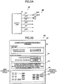
- FIG. 5A is a diagram for illustrating a connection between the output unit and each speaker in order to illustrate a connection example by the user.
- FIG. 5B is a diagram for illustrating a display example of the portable terminal.
- the user wants to use the speaker 300FL and the speaker 300FR in order to listen to two-channel stereo sound.
- the speaker 300FL and the speaker 300FR are correctly connected to the speaker connector 15FL and the speaker connector 15FR, respectively. None of the speakers 300 is connected to a speaker connector 15SW for a subwoofer.
- connection example illustrated in FIG. 5A on the portable terminal 400, the user sets 2.1 channel surround sound, which uses the speaker 300FL, the speaker 300FR, and a speaker 300SW, as the connection mode.
- the connection mode uses the speaker 300FL, the speaker 300FR, and a speaker 300SW, as the connection mode.
- the detection unit 12 detects the actual speaker system configuration to be a two channel configuration, and considers and detects the speaker 300 connected to the FL channel to be the speaker 300FL and the speaker 300 connected to the FR channel to be the speaker 300FR. As a result, the determination unit 13 determines that there is a difference between the actual connection mode indicated by the detection result and the connection mode indicated by the setting information.
- the portable terminal 400 displays in the area 502 a message stating that there is a difference and that prompts the user to correct the connections or to correct the setting.
- the user notices that there is an error in his or her own connection setting, and can set the connection mode to the desired connection mode by inputting a corrected setting.
- connection confirmation processing regarding the connection mode of each speaker 300 is performed.
- the connection confirmation processing may also be performed regarding the connection mode of each content reproduction device 200.
- FIG. 6A is a diagram for illustrating a connection between the input unit and each content reproduction device in order to illustrate a connection example by the user.
- FIG. 6B is a diagram for illustrating a display example of the portable terminal.
- the user wants to listen to sound included in content in the BD player 201, the PC 202, and the video camera 203.
- the connection mode the user sets in the portable terminal 400 that the BD player 201 is to be connected to an HDMI connector 101A (connector number 1), the PC 202 is to be connected to an HDMI connector 101B (connector number 2), and the video camera 203 is to be connected to an HDMI connector 101C (connector number 3).
- connection example illustrated in FIG. 6A the BD player 201 is correctly connected to the HDMI connector 101A and the PC 202 is connected to the HDMI connector 101B, but the video camera 203 is not connected to any of the HDMI connectors.
- the connection example illustrated in FIG. 6A is an example in which the user has forgotten to connect the video camera 203.
- a detection result signal in the HDMI-CEC format is returned from the BD player 201 and the PC 202, but is not returned from the video camera 203.
- the detection unit 12 detects that the BD player 201 is connected to the connector number 1, and the PC is connected to the connector number 2.
- the portable terminal 400 displays in the area 500 of the LCD 402 the connection mode indicated by the connection setting, and displays in the area 501 the actual connection mode indicated by the detection result.
- the portable terminal 400 also displays in the area 502 a message stating that, regarding the HDMI connections, there is a difference between the connection mode indicated by the setting information and the actual connection mode indicated by the detection result, and that prompts the user to correct the connections or the setting.
- the portable terminal 400 displays a reference diagram in the area 503, and as indicated by a highlighted area 506, displays the HDMI connector of a connector number 3, for which a connection error has been determined to exist, in a highlighted manner.
- the AV receiver 100 is not limited to detecting the connection mode of connections that use a speaker cable or an HDMI cable.
- the AV receiver 100 may also be configured to detect the connection mode of connections based on wireless communication that does not use physical cables.
- the detection unit 12 may be configured to detect the presence of a connection, the type, etc., of the content reproduction device 200 connected by Bluetooth communication to the input unit 101 by determining a Bluetooth profile.
- the detection unit 12 may also be configured to detect the speakers 300 connected by Bluetooth communication to the output unit 105.
- the detection unit 12 is not limited to detecting connections by Bluetooth communication.
- the detection unit 12 may also be configured to detect devices connected by a wireless LAN.
- the detection unit 12 is not limited to detecting devices that are directly connected to the AV receiver 100.
- the detection unit 12 may be configured to detect devices connected via a network.
- the detection unit 12 may detect devices that are logically connected to the AV receiver 100.
- the detection unit 12 may be configured to detect, through polling, the presence of a connection, the type, etc., of the content reproduction devices 200 connected by a LAN to the input unit 101.
- the function of the determination unit 13 may be implemented by the portable terminal 400.
- the portable terminal 400 may be configured to acquire the detection result from the detection unit 12 via the communication unit 41, and to determine, in the own terminal, whether or not there is a difference between the connection mode indicated by the setting information and the actual connection mode indicated by the detection result.
- connection confirmation system 900 is not limited to including the portable terminal 400 in order to receive the operation input of the setting by the user.
- the connection confirmation system 900 may be configured to receive the operation input of the setting by the user on a PC including a keyboard and a mouse.
- the connection confirmation system 900 may also be configured to receive an operation input by an apparatus that does not include a device unit, and only includes an operation receiving unit, such as a keyboard, and to perform the display that is based on the determination result by the AV receiver 100.
- connection detection apparatus is not limited to the AV receiver 100.
- the connection detection apparatus may be any apparatus, as long as that apparatus is capable of detecting devices connected to the own apparatus, and has a simple user interface.
- a built-in apparatus such as a public address (PA) mixer, may be used.
- PA public address
- FIG. 7 is a block diagram for illustrating a portion of the configuration of the connection confirmation system 900A.
- connection confirmation system 900A is different from the connection confirmation system 900 according to the first embodiment in the point that the position of each speaker 300 is included in the connection mode. More specifically, in the connection confirmation system 900A, the user can confirm whether or not there is an error in the arrangement of each speaker 300, and whether or not there is an error in the setting of the arrangement, and hence the user can set the arrangement of each speaker 300 to a desired arrangement. A description of configurations that are the same as those in the connection confirmation system 900 is omitted.
- connection confirmation system 900A is different from the connection confirmation system 900 in the point that anAV receiver 100A includes a microphone 107A, a microphone 107X, and a microphone 107Y, the point that a sound pickup signal from each of the microphone 107A, the microphone 107X, and the microphone 107Y is input to an input unit 101A, and the point that a detection unit 12A is configured to detect the position of each speaker 300 based on each sound pickup signal.
- the connection confirmation system 900A is also different from the connection confirmation system 900 in the point that operation input of a setting relating to the position of each speaker 300 is performed on the portable terminal 400.
- the microphone 107A, the microphone 107X, and the microphone 107Y are arranged close to each other. More specifically, the microphone 107X is arranged a predetermined distance d to the right of the microphone 107A, which is arranged at a listening position of the user. The microphone 107Y is arranged the predetermined distance d forward from the microphone 107A. In this case, the direction in which the speaker 300FL and the speaker 300FR are to be arranged from the listening position is considered to be the forward direction.
- the sound pickup signal from each of the microphones 107 is input to a sound pickup unit 11A of the AV receiver 100A.
- the detection unit 12A is configured to detect each sound source position (speaker position) by acquiring each sound pickup signal as a sound pickup result.
- the detection unit 12A calculates the position (XFL, YFL) of the speaker 300FL by using the following expressions based on the Pythagorean theorem.
- the X-axis represents the azimuth (corresponding to the right direction) from the position of the microphone 107A to the position of the microphone 107X
- the Y-axis represents the azimuth (corresponding to the forward direction) from the position of the microphone 107A to the position of the microphone 107Y.
- XFL d 2 + r 2 A_FL ⁇ r 2 X_FL / 2 d
- YFL d 2 + r 2 A_FL ⁇ r 2 Y_FL / 2 d
- the distance d represents the distance between each of the microphones 107.
- a distance rA_FL represents the distance between the position of the speaker 300FL and the position of the microphone 107A. The distance rA_FL is calculated based on the speed of sound and the time taken from output of the test sound until the sound is directly detected in an impulse response included in the sound pickup signal of the microphone 107A.
- a distance rX_FL represents the distance between the position of the speaker 300FL and the position of the microphone 107X
- a distance rY_FL represents the distance between the position of the speaker 300FL and the position of the microphone 107Y.
- the detection unit 12A similarly detects the position (XFR, YFR) of the speaker 300FR by using the sound pickup signal received when a test sound is output by the sound pickup unit 11A from the speaker 300FR.
- the detection unit 12A also detects in the same manner the position of each speaker 300 connected to other channels.
- FIG. 8A is a diagram for illustrating a connection between the output unit and each speaker in order to illustrate a speaker arrangement
- FIG. 8B is a plan schematic view of a listening environment in order to illustrate the arrangement of each speaker in the listening environment.
- FIG. 9 is a diagram for illustrating a display example of the portable terminal.
- each speaker 300 around the listening environment as illustrated in FIG. 8B in order to listen to seven channels (FL, FR, C, SL, SR, PL, and PR), including presence speakers.
- the speaker 300PL and the speaker 300PR which are presence speakers, are arranged forward of the listening position
- the speaker 300SBL and the speaker 300SBR which are surround back speakers, are arranged behind the listening position.
- the speaker 300SBL and the speaker 300SBR are erroneously connected to the speaker connector 15PL and the speaker connector 15PR, which are for presence speakers.
- the speaker 300PL and the speaker 300PR, which are presence speakers, are not connected to any of the speaker connectors.
- the detection unit 12 considers and detects the speaker 300SBL connected to the speaker connector 15PL of the PL channel and the speaker 300SBR connected to the speaker connector 15PR of the PR channel as being arranged behind the listening position. Therefore, the determination unit 13 determines that there is a difference between the connection mode indicated by the setting information (i.e., that a presence speaker is to be arranged forward of the listening position) and the detected actual connection mode (i.e., that a presence speaker is to be arranged behind the listening position) .
- the portable terminal 400 displays in the area 502 of the LCD 402 a message stating, for example, that there is a difference between the connection mode indicated by the setting information and the actual connection mode indicated by the detection result regarding the speaker arrangement.
- the user notices that there is an error in the speaker arrangement, and can set the connection mode for the speaker arrangement to the desired connection mode.
- the portable terminal 400 displays, as the reference diagram to be shown in the area 503 of FIG. 9 , the actual arrangement of each speaker 300 based on the detection result in an area 507, and the arrangement of each speaker 300 based on the setting information in an area 508.
- the portable terminal 400 also displays differences between the set arrangement and the actual arrangement of each speaker 300 in a highlighted area 509A and a highlighted area 509B.
- the arrangement of each speaker 300 is displayed by the portable terminal 400 in the form of a diagram, and hence the user can intuitively understand whether or not there is an error in the arrangement setting or an error in the actual arrangement.
- the AV receiver 100 and the AV receiver 100A are configured to perform connection confirmation processing regarding the connection mode of devices directly connected to the own receiver and the AV receiver 100A.
- the AV receiver 100 and the AV receiver 100A may also be configured to perform connection confirmation processing regarding devices indirectly connected to the own receiver and the AV receiver 100A.
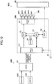
- FIG. 10 is a block diagram for illustrating a portion of the configuration of the connection confirmation system according to a third embodiment of the present invention.
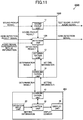
- FIG. 11 is a function block diagram of the AV receiver and the portable terminal according to the third embodiment.
- a connection confirmation system 900B according to the third embodiment is configured to determine a difference between the setting information from the user and the actual connection mode indicated by the detection result regarding the connection mode of devices (microphone 204B1 and guitar 204B2) indirectly connected via a mixer 204, and to perform a display that is based on that difference by the portable terminal 400.
- the mixer 204 is connected to an input unit 101B of anAV receiver 100B by an audio cable.
- the microphone 204B1 and the guitar 204B2 are each connected to the mixer 204 by an audio cable.
- the microphone 204B1 is configured to superimpose identification (ID) information unique to the device on an audio signal generated by picking up sound, and to output the superimposed audio signal to the mixer 204.
- the guitar 204B2 is configured to generate musical sound based on an operation by the user, to superimpose ID information unique to the device on an audio signal of the musical sound, and to output the superimposed audio signal to the mixer 204.
- the mixer 204 is configured to extract the ID information from each input audio signal.
- the mixer 204 is also configured to mix together each of the input audio signals, and to superimpose on the resultant mixed audio signal an information pair including the extracted ID information and ID information on the own mixer so that the own mixer is understood as being a parent device (and the microphone 204B1 and the guitar 204B2 are considered as being child devices).
- a parent-child relation of the connections between the devices is included in the superimposed information. It is desired that the information be superimposed on the audio signal in a higher bandwidth than the bandwidth normally used for audio signals (e.g., in a bandwidth of 20 kHz or more).
- the audio signal superimposed with the plurality of pieces of ID information is input to a detection unit 12B of the AV receiver 100B.
- the detection unit 12B is configured to extract the plurality of pieces of ID information from the input audio signal.
- the input audio signal also includes information indicating the parent-child relation of the connections, and hence the detection unit 12B detects that the microphone 204B1 and the guitar 204B2 are connected to the mixer 204.
- the portable terminal 400 may perform a display that is based on a difference between the connection mode of the devices connected to the mixer 204 input by the user to the portable terminal 400 and the actual connection mode of the mixer 204 detected by the detection unit 12B.
- connection confirmation system 900B is not limited to one mixer 204 being connected to the input unit 101B of the AV receiver 100B.
- a plurality of mixers 204 may be connected in multiple stages. Even for complicated cabling in which a plurality of mixers 204 are connected inmultiple stages, the connection confirmation system 900B performs a display that is based on a difference between the connection mode indicated by the setting information by the user and the detected actual connection mode, and hence the connection confirmation system 900B allows the user to notice whether or not there is an error in the setting or in the connections.
- FIG. 12 is a diagram for illustrating the first modified example. Specifically, an outline of a processing flow by the portable terminal in the first modified example is illustrated in FIG. 12 .
- the AV receiver 100 includes AV1 to AV7 as HDMI inputs, and HDMI OUT1 and HDMI OUT2 as HDMI outputs.
- the devices that the user wants to connect are a BD player, a set-top box (STB), and a television (TV) monitor.
- STB set-top box
- TV television
- the user inputs the HDMI device (s) that he/she wants to connect on a setting screen of the portable terminal 400 in which a setting assistance application has been installed (S101).
- the user wants to connect the BD player, the STB, and the TV monitor as HDMI inputs, for example, and hence the user inputs the device IDs for identifying those devices by using the operation input unit 43 of the portable terminal 400.
- the setting assistance application may be installed and used on another device.
- the portable terminal 400 acquires a recommended connection method (recommended connection information) based on the input device (s) (e.g. , based on the device ID (s)), and displays the acquired recommended connection method on the display unit 44 (S102).
- the recommended connection method is information indicating that it is recommended that an HDMI terminal be used for the connection of the device (s).
- the recommended connection method corresponds to information in which the user has associated a connection with each desired device in advance. More specifically, in the above-mentioned example, as shown in FIG.
- the portable terminal 400 acquires recommended connection information indicating that the BD player 201 is to be connected to AV1, the STB is to be connected to AV3, and the TV monitor is to be connected to HDMI OUT1, and displays the acquired recommended connection information on the screen of the portable terminal 400.
- the recommended connection information shown in FIG. 13 is an example, and the recommended connection information is not limited to that example.
- the recommended connection information may be acquired by another method, such as by determining the recommended connection information based on a combination of the HDMI devices to be connected.
- the user inputs a desired connection method while referring to the connection method displayed in Step S102, and the portable terminal 400 acquires information (desired connection information) indicating that desired connection method (S103).
- the desired connection method corresponds to, for example, information in which the device ID(s) and the HDMI terminal(s) are associated with one another.
- the recommended connection method may be changed by the user. Then, the user connects the device (s) to the main body while referring to the displayed connection method.
- the portable terminal 400 acquires main body setting information on the setting of the AV receiver 100 based on the desired connection information (S104).
- the main body setting information is, for example, information indicating the setting regarding the connection mode, and corresponds to information in which an input terminal, an output terminal, etc., are associated with each device.
- the main body setting information may also include information indicating various settings, such as an input setting, an HDMI output setting, a reproduction mode setting, an audio setting such as tone control, a sound field setting in accordance with each piece of video content, and a video setting such as a video mode.
- the portable terminal 400 acquires connection state information acquired by the AV receiver 100 indicating a connection state between each terminal of the AV receiver 100 and each HDMI device (S105).
- the connection state information corresponds to information indicating, for example, the fact that the BD player is connected to HDMI input: AV1. Detection of the connection state is performed by the AV receiver 100 using HDMI Extended Display Identification Data (EDID)/CEC.
- EDID Extended Display Identification Data
- the connection state information may also be acquired based on an instruction from the portable terminal 400.
- the portable terminal 400 judges whether or not the connection relation between each HDMI terminal and each HDMI device indicated by the main body setting information acquired in Step S104 and the connection relation between each HDMI terminal and each HDMI device indicated by the connection state information match (S106). This judgment is performed by, for example, the control unit 42 of the portable terminal 400. Specifically, for example, as shown in FIG. 13 , when the main body setting information indicates the connection relation HDMI terminal: AV1 for the BD player, the portable terminal 400 judges that there is a match when the connection state information indicates that the BD player is connected to HDMI terminal: AV1.
- the portable terminal 400 When it is judged that the connection relations do not match, the portable terminal 400 notifies the user of mismatch connection relation information indicating that the connection relations do notmatch (S107) .
- mismatch connection relation information indicating that the connection relations do notmatch
- the portable terminal 400 when the user connected the BD player to HDMI input: AV1, but erroneously connected the STB to HDMI input: AV5 and the TV monitor to HDMI output: HDMI OUT2, this means that an input is missing because, in the main body setting information, the connection destination of the STB is, as shown in SCENE 2, HDMI input: AV3. Similarly, an output is missing because the connection destination of the TV monitor is HDMI OUT1.
- the mismatch connection relation information contains, for example, information indicating that the STB is connected to HDMI input: AV5 in place of HDMI input: AV3.
- the notification corresponds to, for example, the display on the display unit 44 of the information indicating the mismatch connection relation information.
- the control unit 42 of the portable terminal 400 judges whether or not the mismatch in connection relations can be handled by changing the connection relation indicated by the main body setting information based on the connection state information, namely, whether or not the connection relation is changeable in accordance with the connection state information (S108).
- the mismatch can be handled when the HDMI output is changed from HDMI output: HDMI OUT1 to HDMI output: HDMI OUT2 in the main body setting information of SCENE 2, and hence the control unit 42 of the portable terminal 400 judges that the mismatch can be handled.
- the control unit 42 of the portable terminal 400 judges that the mismatch cannot be handled because the mismatch cannot be handled by a change in the main body setting information.
- the judgment regarding whether or not the mismatch can be handled as described herein is an example, and may be performed in some other manner.
- a judgment result e. g. , a display on the display unit 44 indicating that the mismatch can be handled by a change in the main body setting information
- the above-mentioned judgment is performed by, for example, the control unit 42 of the portable terminal 400.
- main body setting information is generated in which the connection relation indicated by the main body setting information has been changed (S109). Specifically, for example, in the above-mentioned example, main body setting information is generated in which the HDMI output in the main body setting information of SCENE 2 has been changed from HDMI output: HDMI OUT1 to HDMI output: HDMI OUT2.
- the main body setting information is generated by, for example, the control unit 42.
- the portable terminal 400 transmits the main body setting information to the AV receiver 100 (S110). Specifically, the portable terminal 400 transmits, when it is judged in Step S106 that the connection relations match, the main body setting information acquired in Step S104 to the AV receiver 100 via the communication unit 41, or transmits the main body setting information generated in Step S109 to the AV receiver 100.
- the AV receiver 100 reflects the received main body setting information in the original main body setting information, and then ends the processing. The transmission performed in this step is performed via, for example, the communication unit 41.
- Step S111 when it is judged in Step S108 that the mismatch cannot be handled, the user is notified to correct the connection (S111). Specifically, for example, a message stating "Please correct the connection" is displayed on the display unit 44. The above-mentioned mismatch connection information may also be displayed. As a result of this processing, the user can correct the connection while referring to the mismatch connection information. The processing then returns to Step S105, and the portable terminal 400 again judges whether or not the connection relations match, for example.
- the above-mentioned first modified example is an example.
- the components in the first modified example may be replaced with components that are essentially the same or with components that provide essentially the same operation and effect.
- Steps S106 and S108 are performed on the portable terminal 400 side.
- the processing may be performed on the AV receiver 100 side. Specifically, such a case is now described with respect to FIG. 15 and FIG. 16 .
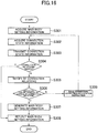
- FIG. 15 and FIG. 16 are diagrams for illustrating a second modified example of the first embodiment.
- An outline of a processing flow by the portable terminal in the second modified example is illustrated in FIG. 15
- an outline of a processing flow by the AV receiver in the second modified example is illustrated in FIG. 16 .
- description of processing etc. that is the same as in the first modified example is omitted.
- the user inputs the HDMI device (s) that he/she wants to connect (S201).
- the portable terminal 400 acquires the recommended connectionmethod (recommended connection information) based on the input HDMI device(s), and displays the acquired recommended connection method on the screen (S202).
- the user inputs the connection method desired by the user while referring to the connection method displayed in Step S202, and the portable terminal 400 acquires information indicating that desired connection method (desired connection information) (S203). Then, the user connects the HDMI device(s) to the AV receiver 100 while referring to the displayed connection method.
- the portable terminal 400 generates main body setting information based on the acquired connection information, and transmits the generated main body setting information to the AV receiver 100 (S204).
- the portable terminal 400 judges whether or not the mismatch connection information has been acquired from the AV receiver 100 (S205) . The judgment is performed by, for example, the control unit 42.
- the portable terminal 400 notifies the user of the mismatch connection information (S206).
- the portable terminal 400 ends the processing. Specifically, the portable terminal 400 judges that the mismatch connection information has not been acquired when, for example, the mismatch connection information has not been acquired within a predetermined period after the transmission of the main body setting information in Step S204.
- the portable terminal 400 judges whether or not a correction notification instruction has been acquired from the AV receiver 100 (S207). When it is judged that the correction notification instruction has been acquired, the portable terminal 400 notifies the user to correct the connection (S208), and the processing returns to Step S205. As described above, the notification corresponds to, for example, displaying a message such as "Please correct the connection" on the display unit 44. On the other hand, when it is judged that the correction notification instruction has not been acquired, the portable terminal 400 ends the processing. The portable terminal 400 judges that the correction notification instruction has not been acquired when, for example, the correction notification instruction has not been acquired from the AV receiver 100 within a predetermined period after acquisition of the mismatch connection information in Step S205.
- the AV receiver 100 acquires the main body setting information (S301). The AV receiver 100 then acquires the connection state information indicating the connection state between the HDMI device(s) and the HDMI terminal(s) of the AV receiver 100 (S302).
- the AV receiver 100 transmits the acquired connection state information to the portable terminal 400 (S303).
- the AV receiver 100 judges whether or not the connection relation between the HDMI terminal (s) and the HDMI device (s) indicated by the main body setting information acquired in Step S301 and the connection relation between the HDMI terminal(s) and the HDMI device(s) indicated by the connection state information match (S304).
- the AV receiver 100 transmits the non-matching connection relations (mismatch connection information) to the portable terminal 400 (S305). The AV receiver 100 then judges whether or not the mismatch in connection relations can be handled by changing the connection relation indicated by the main device setting information based on the connection state information (S306).
- the AV receiver 100 When it is judged that the mismatch can be handled, the AV receiver 100 generates main body setting information in which the connection relation indicated by the main body setting information has been changed (S307). The AV receiver 100 then reflects the changed main body setting information (S308). Specifically, when it is judged in Step S304 that the connection relations match, the AV receiver 100 reflects the main body setting information acquired in Step S301, or reflects the main body setting information generated in Step S307 in the original main body setting information. Then, the AV receiver 100 ends the processing. On the other hand, when it is judged in Step S306 that the mismatch cannot be handled by a change, the AV receiver 100 transmits to the portable terminal 400 an instruction to perform a connection correction notification (S309), and returns the processing to Step S302.
- the mismatch may be handled by a change in the main body setting information, and user convenience maybe further improved. More specifically, for example, there is no longer a need to cause the user to correct a connection every time the user makes an error in the connection between the HDMI device (s) and the HDMI terminal(s).
- the present invention is not limited to the first and second modified examples.
- the components described in the first and second modified examples may be replaced with components that are essentially the same, components that provide essentially the same operation and effect, or components capable of achieving the same purpose.
- the setting assistance application is installed in the portable terminal 400.
- the setting assistance application may be installed in another device, for example, in the AV receiver 100 itself.
- FIG. 17 is a diagram for illustrating the modified example of the second embodiment. Specifically, an outline of a processing flow by the portable terminal in the second modified example of the second embodiment is illustrated in FIG. 17 . A description of points that are the same as in the first and second modified examples of the first embodiment is omitted.
- the flow outline described below is an example. This modified example is not limited to the following flow outline.
- the user inputs the device(s) (including speaker(s)) that he/she wants to connect (S401). Specifically, for example, the portable terminal 400 acquires the device ID and speaker ID indicating each speaker in accordance with the inputs by the user.
- the portable terminal 400 acquires the device ID and speaker ID indicating each speaker in accordance with the inputs by the user.
- each speaker corresponds to, for example, a left front speaker, a right front speaker, a center speaker, a left surround speaker, a right surround speaker, etc.
- the portable terminal 400 acquires a recommended connection method (recommended connection information) based on the input device ID (s) and speaker ID (s), and displays the acquired recommended connection method on the screen (S402).
- the recommended connection information contains information on the connection of each device to the AV receiver 100 and the connection of each speaker to the AV receiver 100.
- the user inputs a desired connection method while referring to the recommended connection method displayed in Step S402, and the portable terminal 400 acquires information (desired connection information) indicating that desired connection method (S403).
- the user connects the device(s) and the speaker(s) to the terminals of the AV receiver 100 while referring to the displayed connection method.
- the recommended connection method includes information indicating the connection relation between each speaker and the terminals of the AV receiver 100.
- the portable terminal 400 generates the main body setting information that the AV receiver 100 needs to have based on the acquired connection information, and transmits the main body setting information to the AV receiver 100 (S404).
- the main body setting information contains a setting relating to output to each speaker.
- the portable terminal 400 transmits to the AV receiver 100 a sound emission instruction for causing the speaker (s) identified by the main body setting information to emit a sound (S405).
- the portable terminal 400 picks up the sound emitted in accordance with the sound emission instruction (S406).
- the AV receiver 100A includes microphones 107A, 107X, and 107Y.
- the portable terminal 400 includes a microphone, and sound emitted by that microphone is picked up.
- the user may be notified to move the portable terminal 400 to a position at which the portable terminal 400 picks up sound at the predetermined position.
- the portable terminal 400 detects the speaker position based on the sound pickup result (S407).
- the detection is performed by the control unit 42 of the portable terminal 400, for example.
- the specific detection method is the same as in the above-described second embodiment, and hence a description thereof is omitted here.
- the portable terminal 400 judges whether or not the detected speaker position and the position corresponding to the speaker indicated by the desired connection information match (S408). Specifically, for example, the control unit 42 of the portable terminal 400 judges whether or not the speaker position indicated by the main body setting information, which contains information indicating the speaker position, and the detected speaker position match.
- the portable terminal 400 transmits a reflect instruction to the AV receiver 100 to reflect the main body setting information in the AV receiver 100 (S409). Based on the reflect instruction, the AV receiver 100 reflects the main body setting information.
- the portable terminal 400 notifies the user of mismatch connection relation information indicating that the connection relations do not match (S410).
- the notification is performed by, for example, displaying on the display unit 44 mismatch connection relation information indicating, for example, that the center speaker is connected to the connection terminal of the left surround back speaker.
- the notification may also include, for example, a message prompting the user to correct the connection. The user corrects the speaker connection in accordance with the notification, and the processing then returns to Step S405.
- the present invention is not limited to the above-mentioned second modified example.
- Each of the components described in the above-mentioned modified example may be replaced by substantially the same component, a component having the same action and effect, and a component that may achieve the same object.
- connection confirmation system may also be configured to input only speakers, and to detect speaker connections.
- connection detection apparatus in the scope of claims corresponds to an apparatus having a function of detecting a connection of a device etc. More specifically, for example, the connection detection apparatus corresponds to the AV receiver 100 when detecting connections by using the AV receiver 100, and corresponds to the portable terminal 400 when detecting connections by using the portable terminal 400.
- the setting of the connection mode in the scope of claims includes, for example, the above-mentioned main body setting information.
- a connection confirmation system including: a connection detection apparatus; and an information processing apparatus, the connection detection apparatus and the information processing apparatus being configured to communicate to and from each other, the information processing apparatus including a receiving unit configured to receive an input of a setting relating to a connection mode of a device to be connected to the connection detection apparatus, the connection detection apparatus including a detection unit configured to detect a connection mode of an actually-connected device, the connection detection apparatus or the information processing apparatus including a determination unit configured to determine a difference between the actual connection mode detected by the detection unit and the connection mode indicated by the setting received by the receiving unit, the information processingapparatusincluding a display unit configured to perform a display based on a determination result of the determination unit.
- connection detection apparatus is, for example, a sound processing apparatus configured to output to a speaker an audio signal for each channel
- the connection mode is a mode of a connection between the sound processing apparatus and the speaker
- the detection unit is configured to detect an actual connection mode of each channel and each speaker by outputting an audio signal of a test sound to the speaker and picking up a test sound by using a microphone.
- the information processing apparatus is, for example, a portable terminal including a computer having a mouse and a keyboard as a receiving unit, and a display device equipped with a touch panel as a receiving unit and a display unit.
- the information processing apparatus is configured to execute various kinds of application programs, including a connection confirmation program that is described later.
- connection detection apparatus is not limited to physical connections via a cable, and connections may be made via wireless communication directly between two devices.
- wireless communication refers to, for example, wireless LAN and Bluetooth (registered trademark) communication.
- the connection mode indicates, for example, the presence of a connection of a device to each connector of the connection detection apparatus, and the number of connected devices.
- many related art sound processing apparatuses are configured to automatically detect the speakers that are actually connected, to receive operation inputs by the user by using only a power button, a volume change knob, and cursor keys, and to cause a television etc. to display the operation input content and a speaker detection result. Therefore, in the related art sound processing apparatus, input of the connection mode desired by the user is not determined, and a simple user interface is implemented that specializes in displaying the speaker detection result and completion ofan operation based onfewer operation inputs. However, the related art sound processing apparatus implement a simple user interface, and hence there are limits on the display content and the input method. In the related art sound processing apparatus, there are difficulties in directly receiving the speaker connection mode desired by the user, and there are difficulties in displaying a difference between the actual speaker detection result and the speaker connection mode desired by the user.
- the user uses an erroneous connection state as is, and cannot sufficiently produce the sound effect that the related art sound processing apparatus has.
- a user who is not used to the sound processing apparatus may often use the sound processing apparatus by using an erroneous connection state as is.
- connection confirmation system is configured to implement, by an information processing apparatus including a receiving unit, an interface capable of receiving input of a volume change etc., as well as the connection mode desired by the user.
- the display unit is capable of allowing the user to confirm a difference between the connection mode of the sound processing apparatus desired by the user and the actual connection mode detected by the sound processing apparatus by performing a display that is based on the difference.
- the display unit may be included in the sound processing apparatus, but it is desired that the display unit be included in the information processing apparatus.
- a display that is based on the setting input of the connection mode desired by the user and a difference between the connection mode desired by the user and the detected actual connection mode is implemented by one information processing apparatus, which allows the user to confirm the difference more easily.
- a display that is based on the input of the connection mode desired by the user and a difference between the connection mode desired by the user and the detected actual connection mode is realized by a connection confirmation program executed by the information processing apparatus.
- the sound processing apparatus is configured to detect, when the user inputs on the connection confirmation program a setting in which surround back speakers are to be used, but erroneously connects the surround back speakers to the presence speaker connectors of the sound processing apparatus, that presence speakers are connected.
- the sound processing apparatus is configured to perform a display by the information processing apparatus based on a difference between the connection mode indicated by the detection result (i.e., that surround back speakers are not connected, and presence speakers are connected) and the connection mode indicated by the setting (i.e., that surround back speakers are connected, and presence speakers are not connected).
- connection mode indicated by the setting and the connection mode indicated by the detection result is not limited to the presence of speaker connections.
- the difference may be a connection connector error or the fact that there are extra connections (e.g., when more speaker channels are detected than the number of set channels).
- connection confirmation system is capable of allowing the user to confirm a difference between the connection mode desired by the user (connection mode indicated by the setting) and the actual connection mode without automatically correcting the connection setting. As a result, the user can confirm whether or not there is an error in the actual connections, and correct the connections so as to match the desired connection mode.
- connection confirmation system according to one aspect of the present invention, the user can easily set the connection mode to the desired connection mode.
- the present invention is not limited to a connection confirmation system.
- the present invention may be a connection confirmation program executed by an information processing apparatus. That is, the connection confirmation program is, for example, a connection confirmation program, which is executed in an information processing apparatus, the connection confirmation program being configured to cause the information processing apparatus to execute : a reception step of receiving an input of a setting relating to a connection mode of a device to be connected to a connection detection apparatus; an acquisition step of acquiring, by the connection detection apparatus, a detection result obtained by detecting a connection mode of a device actually connected to the own connection detection apparatus; a determination step of determining a difference between the connection mode indicated by the setting received in the reception step and the actual connectionmode acquired in the acquisition step; and a display step of performing a display based on a determination result of the determination step.
- the connection confirmation program is, for example, a connection confirmation program, which is executed in an information processing apparatus, the connection confirmation program being configured to cause the information processing apparatus to execute : a reception step of receiving an input of
- connection confirmation method is a connection confirmation method, which is executed by using a connection detection apparatus and an information processing apparatus, the connection confirmation method including: a reception step of receiving in the information processing apparatus an input of a setting relating to a connection mode of a device to be connected to the connection detection apparatus; a detection step of detecting a connection mode of a device actually connected to the connection detection apparatus; a determination step of determining a difference between the connection mode indicated by the setting received in the reception step and the actual connection mode acquired in the detection step; and a display step of performing a display based on a determination result of the determination step.
- the present invention is not limited to a connection confirmation system.
- the present invention may be a connection detection apparatus.
- the connection detection apparatus includes: a communication unit configured to communicate to and from an information processing apparatus, which includes a receiving unit configured to receive operation inputs; an acquisition unit configured to acquire from the information processing apparatus a setting relating to a connection mode of a device to be connected to the own connection detection apparatus, a detection unit configured to detect a connection mode of a device actually connected to the own connection detection apparatus; a determination unit configured to determine a difference between the actual connection mode detected by the detection unit and the connection mode indicated by the setting acquired by the acquisition unit; and a display unit configured to perform a display based on a determination result of the determination unit.
- the acquisition unit is configured to acquire from the information processing apparatus a setting relating to a connection mode of a device to be connected indirectly to the connection detection apparatus
- the detection unit is configured to detect a connection mode of a device actually connected indirectly to the connection detection apparatus
- the determination unit is configured to determine a difference between the connection mode of the device to be indirectly connected indicated by the setting acquired by the acquisition unit and the connection mode of the device actually connected indirectly to the connection detection apparatus detected by the detection unit.
- the user connects the connection detection apparatus as a parent device and connects a device connected to the connection detection apparatus as a child device.
- a grandchild device is further connected to the child device.
- the acquisition unit is configured to detect the actual connection mode of the connection between the child device and the grandchild device.
- the information processing apparatus includes a receiving unit, and hence the user can perform setting input regarding the connection mode of a device connected to the connection detection apparatus. Further, the display unit performs a display based on a difference between the connection mode indicated by the setting and the actual connection mode, and hence the user can confirm whether or not there is an error in the connection setting.
- connection confirmation system a connection confirmation program, a connection confirmation method, and a connection detection apparatus, which are capable of detecting and informing a user of a difference between a connection mode of a connected device and the connection mode desired by the user.
- the sound processing apparatus serving as the connection detection apparatus is configured to detect, when the user inputs on the information processing apparatus a setting in which surround back speakers are to be used, but erroneously connects the surround back speakers to the presence speaker connectors of the sound processing apparatus, that presence speakers are connected.
- the sound processing apparatus is configured to perform a display that is based on a difference between the connection mode indicated by the detection result (i.e., that surround back speakers are not connected, and presence speakers are connected) and the connection mode indicated by the setting (i.e., that surround back speakers are connected, and presence speakers are not connected). As a result, the user can confirm that there is an error in the actual connections.
Landscapes
- Engineering & Computer Science (AREA)
- Theoretical Computer Science (AREA)
- Physics & Mathematics (AREA)
- General Engineering & Computer Science (AREA)
- General Physics & Mathematics (AREA)
- Computing Systems (AREA)
- Signal Processing (AREA)
- Acoustics & Sound (AREA)
- Quality & Reliability (AREA)
- Health & Medical Sciences (AREA)
- General Health & Medical Sciences (AREA)
- Otolaryngology (AREA)
- Mathematical Physics (AREA)
- Stereophonic System (AREA)
- Circuit For Audible Band Transducer (AREA)
Abstract
Description
- The present invention relates to a connection confirmation system, a connection confirmation program, a connection confirmation method, and a connection detection apparatus.
- Hitherto, there has been proposed to detect a device connected to an own apparatus. For example, a sound processing apparatus described in
Patent Literature 1 is configured to detect a speaker actually connected to the own apparatus by causing the speaker to output a test sound and by picking up the output test sound by using a microphone. - The sound processing apparatus described in Patent Literature 1 (
JP 2006-174094 A Patent Literature 1 is configured to automatically correct various settings such that, when only front left/right (L/R) speakers and surround L/R speakers are connected to the own apparatus, for example, those front L/R speakers and surround L/R speakers are detected, to thereby invalidate the setting of unconnected speakers (e.g., a center (C) channel speaker). - However, the sound processing apparatus described in
Patent Literature 1 is configured to automatically correct the setting based only on the actual connection mode, and hence there are cases in which the corrected connection mode does not match the connection mode desired by a user. - For example, the user may want to generate a sound field by using 7-channel surround sound (front left (FL), front right (FR), center (C), surround left (SL), surround right (SR), surround back left (SBL), and surround back right (SBR) channels) including surround back speakers. In this case, when the user erroneously connects the surround back speakers to presence speaker connectors of the sound processing apparatus, the sound processing apparatus detects that presence speakers are connected, and hence generates the sound field by using 7-channel surround sound (FL, FR, C, SL, SR, PL, and PR channels) including presence speakers, which does not conform to the setting intended by the user.
- In other words, in this example, as long as the configuration of the connected speakers is not a configuration that cannot be implemented (e.g., a configuration including only an FL speaker and an SL speaker), the sound processing apparatus automatically generates the sound field based on a connection setting including presence speakers. Therefore, such a sound processing apparatus outputs a sound from each detected speaker, but the sounds set to be output from the setting position of the presence speakers are output from the setting position of the surround back speakers. As a result, unless the user notices a difference between a desired connection mode and the actual connection mode, the user cannot obtain the desired sound effect.
- Therefore, it is a primary object of the present invention to provide a connection confirmation system, a connection confirmation program, a connection confirmation method, and a connection detection apparatus, which are capable of detecting and informing a user of a difference between a connection mode of a connected device and a connection mode desired by the user.
- According to one embodiment of the present invention, there is provided a connection confirmation system, including: a connection detection apparatus; and an information processing apparatus, the connection detection apparatus and the information processing apparatus being configured to communicate to and from each other, the information processing apparatus including a receiving unit configured to receive an input of a setting relating to a connection mode of a device to be connected to the connection detection apparatus, the connection detection apparatus including a detection unit configured to detect a connection mode of an actually-connected device, the connection detection apparatus or the information processing apparatus including a determination unit configured to determine a difference between the actual connection mode detected by the detection unit and the connection mode indicated by the setting received by the receiving unit, the information processing apparatus including a display unit configured to perform a display based on a determination result of the determination unit.
- According to one embodiment of the present invention, there is provided a connection confirmation program, which is executed in an information processing apparatus, the connection confirmation program being configured to cause the information processing apparatus to execute: a reception step of receiving an input of a setting relating to a connection mode of a device to be connected to a connection detection apparatus; an acquisition step of acquiring, by the connection detection apparatus, a detection result obtained by detecting a connection mode of a device actually connected to the own connection detection apparatus; a determination step of determining a difference between the connection mode indicated by the setting received in the reception step and the actual connection mode acquired in the acquisition step; and a display step of performing a display based on a determination result of the determination step.
- According to one embodiment of the present invention, there is provided a connection confirmation method, which is executed by using a connection detection apparatus and an information processing apparatus, the connection confirmation method including: a reception step of receiving in the information processing apparatus an input of a setting relating to a connection mode of a device to be connected to the connection detection apparatus; a detection step of detecting a connection mode of a device actually connected to the connection detection apparatus; a determination step of determining a difference between the connection mode indicated by the setting received in the reception step and the actual connection mode acquired in the detection step; and a display step of performing a display based on a determination result of the determination step.
- According to one embodiment of the present invention, there is provided a connection detection apparatus, including: an acquisition unit configured to acquire a setting relating to a connection mode of a device to be connected to a sound processing apparatus; a detection unit configured to detect a connection mode of a device actually connected to the sound processing apparatus; and a determination unit configured to determine a difference between the actual connection mode detected by the detection unit and the connection mode indicated by the setting acquired by the acquisition unit.
-
-
FIG. 1 is a block diagram for illustrating a portion of a configuration of a connection confirmation system according to a first embodiment of the present invention. -
FIG. 2 is a function block diagram of an AV receiver and a portable terminal according to the first embodiment. -
FIG. 3(A) is a flowchart for illustrating operation of the portable terminal, andFIG. 3(B) is a flowchart for illustrating operation of the AV receiver. -
FIG. 4A is a diagram for illustrating a connection between an output unit and each speaker in order to illustrate a connection example by a user, andFIG. 4B is a display example of the portable terminal. -
FIG. 5A is a diagram for illustrating a connection between the output unit and each speaker in order to illustrate a connection example by the user, andFIG. 5B is a display example of the portable terminal. -
FIG. 6A is a diagram for illustrating a connection between an input unit and each content reproduction device in order to illustrate a connection example by the user, andFIG. 6B is a display example of the portable terminal. -
FIG. 7 is a block diagram for illustrating a portion of a configuration of a connection confirmation system according to a second embodiment of the present invention. -
FIG. 8A is a diagram for illustrating a connection between the output unit and each speaker in order to illustrate a speaker arrangement, andFIG. 8B is a plan schematic view of a listening environment in order to illustrate the arrangement of each speaker in the listening environment. -
FIG. 9 is a diagram for illustrating a display example of the portable terminal. -
FIG. 10 is a block diagram for illustrating a portion of a configuration of a connection confirmation system according to a third embodiment of the present invention. -
FIG. 11 is a function block diagram of an AV receiver and a portable terminal according to the third embodiment. -
FIG. 12 is a flowchart for illustrating a first modified example of the first embodiment. -
FIG. 13 is a diagram for showing an example of recommended connection information. -
FIG. 14 is a diagram for illustrating an example of main body setting information. -
FIG. 15 is a flowchart for illustrating a second modified example of the first embodiment. -
FIG. 16 is a flowchart for illustrating the second modified example of the first embodiment. -
FIG. 17 is a flowchart for illustrating a modified example of the second embodiment. - A
connection confirmation system 900 according to a first embodiment of the present invention is described with reference toFIG. 1 ,FIG. 2 ,FIG. 3 (A), and FIG. 3 (B) .FIG. 1 is a block diagram for illustrating a portion of a configuration of theconnection confirmation system 900.FIG. 2 is a function block diagram of anAV receiver 100 and aportable terminal 400.FIG. 3 (A) is a flowchart for illustrating operation of theportable terminal 400, andFIG. 3(B) is a flowchart for illustrating operation of theAV receiver 100. - First, an outline of the
connection confirmation system 900 is described. In theconnection confirmation system 900, the user performs on aportable terminal 400 an operation input of a setting regarding a connection mode of a device to be connected to an audiovisual (AV)receiver 100. TheAV receiver 100 is configured to determine a difference between an actual connection mode determined by detecting the devices that are actually connected to the own receiver and the connection mode set by the user. Theportable terminal 400 is configured to perform a display that is based on the determination result. In this manner, theconnection confirmation system 900 according to the first embodiment allows the user to confirm whether or not there is an error in the actual connection, and to set the connection mode of theAV receiver 100 to the connection mode that is desired by the user. - As illustrated in
FIG. 1 , theconnection confirmation system 900 includes theAV receiver 100, a plurality ofcontent reproduction devices 200, a plurality ofspeakers 300, and theportable terminal 400. TheAV receiver 100 corresponds to the connection detection apparatus according to the present invention. InFIG. 1 , transmission and reception of signals and information via physical cables and internal wiring are represented as the solid lines, and transmission and reception of information by wireless communication are represented as the dotted lines. - The
AV receiver 100 includes aninput unit 101, a digital signal processor (DSP) 102, a central processing unit (CPU) 103, amemory 104, anoutput unit 105, and a radio frequency integrated circuit (RFIC) 106. - The
input unit 101 is configured to receive content data from eachcontent reproduction device 200, and to output to the DSP 102 an audio signal extracted from the content data. A sound pickup signal from amicrophone 107 is input to theinput unit 101. - As the plurality of
content reproduction devices 200, in this embodiment, a Blu-ray Disc (registered trademark) (BD)player 201, a personal computer (PC) 202, and avideo camera 203 are connected to theinput unit 101 of theAV receiver 100. Eachcontent reproduction device 200 is connected to a high-definitionmultimedia interface (HDMI) (registered trademark) connector of theAV receiver 100 via an HDMI cable. Thecontent reproduction devices 200 are not limited to being connected to theinput unit 101 by an HDMI cable. For example, thecontent reproduction devices 200 may be connected to theinput unit 101 by another physical cable, such as a digital optical cable or an analog cable. Thecontent reproduction devices 200 are also not limited to being connected to theinput unit 101 by a physical cable. For example, thecontent reproduction devices 200 may be connected to theinput unit 101 by wireless communication for transmitting audio signals. As the wireless communication, wireless local area network (LAN) communication and Bluetooth (registered trademark) communication may be employed. - A program is stored in the
memory 104. The program is read and executed by theCPU 103. TheCPU 103 is configured to control theinput unit 101, theDSP 102, theoutput unit 105, and theRFIC 106 by reading and executing the program. - The
output unit 105 is configured to amplify each input audio signal, and to output the amplified audio signals to the plurality of speakers 300 (speaker 300FL, speaker 300SL,speaker 300C, speaker 300SR, and speaker 300FR). In this embodiment, eachspeaker 300 is connected to a speaker connector of theAV receiver 100 via a speaker cable. However, even more speakers may be connected to theoutput unit 105. For example, a plurality of speakers supporting 7.1 multi-channel surround sound may be connected to theoutput unit 105. The connection between each of the plurality ofspeakers 300 and theoutput unit 105 is not limited to a physical speaker cable. For example, the plurality ofspeakers 300 and theoutput unit 105 may be connected by wireless communication (e. g. , Bluetooth communication). - The
RFIC 106 is configured to transmit and receive various information to and from theportable terminal 400 under the control of theCPU 103 by using a wireless communication antenna (not shown) . - The
DSP 102 is configured to perform, under the control of theCPU 103, predetermined processing (e.g., volume control, equalizer processing, etc.) on each audio signal input from theinput unit 101. The user performs settings relating to those processes by using operation buttons (e.g. , volume change knob (not shown), frequency change knob (not shown), etc.) on theAV receiver 100. The operation buttons on theAV receiver 100 are specialized for sound processing. - The
portable terminal 400 includes aCPU 401, a liquid crystal display (LCD) 402, atouch panel 403, and anRFIC 404. Each of those parts is connected to a shared bus. - The
CPU 401 is configured to control theLCD 402, thetouch panel 403, and theRFIC 404 in an integrated manner. TheRFIC 404 is configured to transmit and receive various information to and from theRFIC 106 of theAV receiver 100 under the control of theCPU 401 by using a wireless communication antenna (not shown). - The LCD 4 02 and the
touch panel 403 are arranged in an overlapping manner. TheCPU 401 is configured to change display content of theLCD 402 based on touch operations by the user received through thetouch panel 403. Theportable terminal 400 is configured to display a graphical user interface (GUI) based on such processing. - For example, the
portable terminal 400 is configured to display, when a setting start operation input is received by thetouch panel 403, a setting guidance message and a software keyboard on theLCD 402, and to receive key input operations relating to the setting by thetouch panel 403. In this manner, theportable terminal 400 is displaying the GUI, and hence the user can easily input operations relating to the setting. - In this embodiment, the user performs on the portable terminal 400 a setting relating to the connection mode of each device connected to the
input unit 101 and the output unit 105 (plurality ofcontent reproduction devices 200 and plurality of speakers 300) of theAV receiver 100. The setting relating to the connection mode includes, for example, a presence of a connection of thespeaker 300 to each channel, a speaker system configuration (e.g. 2-channel and 5-channel), a presence of a connection of eachcontent reproduction device 200, a connection connector number of eachcontent reproduction device 200, a type of each content reproduction device 200 (device type, such as player, PC, or video camera), the manufacturer of eachcontent reproduction device 200, and a model name of each content reproduction device 200 (player model name, PC model name, and video camera model name). - As illustrated in
FIG. 2 , theAV receiver 100 is configured to implement each function of a sound pickup unit 11, adetection unit 12, adetermination unit 13, and acommunication unit 14. Theportable terminal 400 is configured to implement each function of acommunication unit 41, acontrol unit 42, anoperation input unit 43, and adisplay unit 44. InFIG. 2 , transmission and reception of information are represented as the solid lines, and transmission and reception of audio signals are represented as the dotted lines. As described above, transmission and reception of information between theAV receiver 100 and theportable terminal 400 are performed by wireless communication. The sound pickup unit 11, thedetection unit 12, and thedetermination unit 13 are implemented by theinput unit 101, theoutput unit 105, theCPU 103, and theDSP 102. - The sound pickup unit 11 is configured to output an audio signal of a test sound to each channel. A sound pickup signal from the
microphone 107 is input to the sound pickup unit 11. The sound pickup unit 11 is configured to output, as a sound pickup result, a plurality of sound pickup signals corresponding to a plurality of channels to thedetection unit 12. - The
detection unit 12 is configured to detect whether or not thespeaker 300 is connected to each channel based on the sound pickup result from the sound pickup unit 11. More specifically, when a level of the sound pickup signal for each channel is equal to or more than a predetermined threshold, thedetection unit 12 detects that any one of thespeakers 300 is connected to that channel. Thedetection unit 12 is configured to output information indicating whether or not thespeaker 300 is connected to each channel as a detection result to thedetermination unit 13. This detection result corresponds to the actual connection mode of the plurality ofspeakers 300 connected to theAV receiver 100. - The
detection unit 12 is also configured to detect whether or not any one of thecontent reproduction devices 200 is connected to each HDMI connector of theinput unit 101. More specifically, thedetection unit 12 transmits a detection signal conforming to an HDMI-Consumer Electronics Control (CEC) format from the HDMI connectors of theinput unit 101. A detection result signal conforming to the HDMI-CEC format is input to thedetection unit 12. The detection result signal includes, for example, information on the type and model name of thecontent reproduction device 200. Thedetection unit 12 is also configured to output the detection result indicated by the detection result signal to thedetermination unit 13. The detection result signal corresponds to the actual connection mode of the plurality ofcontent reproduction devices 200 connected to theAV receiver 100. - The
determination unit 13 is configured to determine a difference between the actual connection mode indicated by the detection result output by thedetection unit 12 and the connection mode indicated by setting information acquired from theportable terminal 400. The setting information from theportable terminal 400 is input from thecommunication unit 14. Thedetermination unit 13 is configured to output the determination result of the difference in connection modes to thecommunication unit 14. The determination result includes information indicating whether or not there is a difference in, for example, the presence of a connection of thespeaker 300 to each channel, the speaker system configuration, and the presence of a connection of thecontent reproduction device 200 to each HDMI connector. The determination result also includes information indicating whether or not there is a difference in the connection connector number, the type, the manufacturer, the model name, etc., of eachcontent reproduction device 200. - The
communication unit 14 is configured to transmit the determination result from thedetermination unit 13 to thecommunication unit 41 of theportable terminal 400. Thecommunication unit 14 is also configured to receive setting information from thecommunication unit 41 of theportable terminal 400. - The
control unit 42 of theportable terminal 400 is configured to transmit, when the setting information on the connection mode of the devices (plurality ofcontent reproduction devices 200 and plurality of speakers 300) connected to theinput unit 101 and theoutput unit 105 of theAV receiver 100 is acquired from theoperation input unit 43, the acquired setting information to thecommunication unit 14 of theAV receiver 100 via thecommunication unit 41. Thecontrol unit 42 is configured to cause thedisplay unit 44 to perform, when the determination result of thedetermination unit 13 of theAV receiver 100 is acquired via thecommunication unit 41, a display that is based on that determination result. - However, it is not necessary for the
portable terminal 400 to include, in the own terminal, the program for implementing the display that is based on the operation input of the setting and the determination result. For example, theAV receiver 100 may be configured to acquire the operation input of the setting by causing, when theportable terminal 400 accesses the own terminal via a general-purpose WEB browser, theportable terminal 400 to execute a WEB application for inputting the setting. TheAV receiver 100 may also be configured to cause the WEB application operated by theportable terminal 400 to execute a display that is based on a difference between the connection mode indicated by the setting information acquired via the WEB application and the detected actual connection mode. - The various function units of the
AV receiver 100 and theportable terminal 400 are configured to operate in the following manner in order to perform connection confirmation processing that allows the user to confirm the connectionmode of the devices connected to theAV receiver 100. - As illustrated in
FIG. 3(A) , when theoperation input unit 43 of theportable terminal 400 receives from the user an operation input of a setting relating to the connection mode (S1), thecontrol unit 42 causes thecommunication unit 41 to transmit that setting information (S3). - Then, as illustrated in
FIG. 3(B) , thecommunication unit 14 of theAV receiver 100 receives the setting information from the communication unit 41 (S11). TheAV receiver 100 detects the presence of a connection for each of the plurality of speakers 300 (S12). More specifically, the sound pickup unit 11 outputs the audio signal of the test sound to each channel. When any one of thespeakers 300 is connected to a corresponding channel, the sound pickup unit 11 picks up the test sound output by thatspeaker 300. When the level of each sound pickup signal is equal to or more than a predetermined threshold, thedetection unit 12 detects that any one of thespeakers 300 is connected to the channel corresponding to that sound pickup signal. - In Step S12, the
detection unit 12 also detects eachcontent reproduction device 200 connected in accordance with the HDMI standard. More specifically, thedetection unit 12 outputs a detection signal conforming to the HDMI-CEC format from each HDMI connector. When any one of thecontent reproduction devices 200 is connected to an HDMI connector, and there is a response to the detection signal in the HDMI-CEC format, thedetection unit 12 receives a detection result signal in the HDMI-CEC format from thecontent reproduction device 200. This enables thedetection unit 12 to detect the connection mode, such as the presence of a connection of thecontent reproduction device 200 to each HDMI connector of theinput unit 101, and the type, model name, etc., of thecontent reproduction devices 200 connected to the HDMI connectors of theinput unit 101. TheAV receiver 100 may perform the processing of Step S12 before the processing of Step S11. - Next, the
determination unit 13 determines a difference between the actual connection mode indicated by the detection result acquired in Step S12 and the connection mode indicated by the setting information received in Step S11 (S13). Then, thecommunication unit 14 transmits information on the determination result of thedetermination unit 13 to the communication unit 41 (S14). Thecommunication unit 41 of theportable terminal 400 receives the information on the determination result transmitted from the communication unit 14 (S3). Then, thecontrol unit 42 causes thedisplay unit 44 to perform a display that is based on the determination result (S4). - An example of the connection confirmation processing according to the first embodiment is described with reference to
FIG. 4A and FIG. 4B. FIG. 4A is a diagram for illustrating a connection between the output unit and each speaker in order to illustrate a connection example by the user.FIG. 4B is a diagram for illustrating a display example of the portable terminal. - In the connection example illustrated in
FIG. 4A , on theportable terminal 400, the user performs a connection setting in order to listen to seven channels (FL, FR, C, SL, SR, SBL, and SBR), including surround back speakers (S1). - In the connection example illustrated in
FIG. 4A , the speaker 300FL, the speaker 300FR, the speaker 300SL, the speaker 300SR, and thespeaker 300C are each connected to a speaker connector 15 for the corresponding channel, but the speaker 300SBL for surround back is connected to a speaker connector 15PL for a presence speaker, and the speaker 300SBR for surround back is connected to a speaker connector 15PR for a presence speaker. The speaker 300PL and the speaker 300PR, which are presence speakers, are not connected to any of the speaker connectors 15. In other words, the connection example illustrated inFIG. 4A is an example in which the user has made an error in the connections of the surround back speakers. - In the connection example illustrated in
FIG. 4A , thedetection unit 12 detects that thespeakers 300 are connected to the FL, FR, SL, SR, C, PL, and PR channels (S2). Thedetection unit 12 considers and detects thespeakers 300 connected to the FL, FR, SL, SR, C, PL, and PR channels as respectively being the speaker 300FL, the speaker 300FR, the speaker 300SL, the speaker 300SR, thespeaker 300C, the speaker 300PL, and the speaker 300PR. Therefore, thedetermination unit 13 determines that there is a difference between the connection mode indicated by the setting information (seven channels including surround back speakers) and the detected actual connection mode (seven channels including presence speakers) (S13). - As a result, as illustrated in
FIG. 4B , the connection setting shown in anarea 500, the detection result (corresponding to the actual connection mode) shown in anarea 501, a setting guidance message shown in anarea 502, and a reference diagram shown in anarea 503 are displayed as a connection confirmation result on theLCD 402 of the portable terminal 400 (S4). The reference diagram shown in thearea 503 is a planar schematic diagram in which various connector groups of theAV receiver 100 are arranged. - There is a difference between the connection mode indicated by the setting information and the actual connection mode indicated by the detection result, and hence the
portable terminal 400 displays a message stating that there is a difference and that prompts the user to correct the connections, such as the setting guidance message shown in the area 502 (S4). Theportable terminal 400 displays speaker connections that are different in a highlighted manner, as indicated by a highlighted area 504 (range shown in gray inFIG. 4B ) in thearea 503, and hence the user can easily understand the correct connection. - Thus, the
connection confirmation system 900 is configured to display a difference between the connection mode indicated by the setting information and the actual connection mode indicated by the detection result. As a result, the user can confirm whether or not there is an error in the actual connection, and can set the connection mode to the desired connection mode. - The
connection confirmation system 900 is not limited to the connection error illustrated inFIG. 4A . Theconnection confirmation system 900 also allows the user to confirm whether or not he or she has forgotten a connection (e.g., when the number of detected channels is less than the number of set channels) or has made an extra connection (e.g., when the number of detected channels is more than the number of set channels) by performing on the portable terminal 400 a display that is based on a difference between the number of channels indicated by the setting information and the number of detected channels. - The user performs the connection setting on the
portable terminal 400 displaying the GUI, and hence theconnection confirmation system 900 allows the user to easily input the connection setting. Further, theportable terminal 400, which receives the operation input of the setting, implements the display, and hence the user can input the setting and confirm a difference in the connection mode on oneportable terminal 400. - In the example illustrated in
FIG. 4A and FIG. 4B , there is an error by the user in the connection of thespeakers 300. However, there is now described a case in which there is an error in the setting by the user. This case is described with reference toFIG. 5A and FIG. 5B. FIG. 5A is a diagram for illustrating a connection between the output unit and each speaker in order to illustrate a connection example by the user.FIG. 5B is a diagram for illustrating a display example of the portable terminal. - In the connection example illustrated in
FIG. 5A , the user wants to use the speaker 300FL and the speaker 300FR in order to listen to two-channel stereo sound. In the connection example illustrated inFIG. 5A , the speaker 300FL and the speaker 300FR are correctly connected to the speaker connector 15FL and the speaker connector 15FR, respectively. None of thespeakers 300 is connected to a speaker connector 15SW for a subwoofer. - However, in the connection example illustrated in
FIG. 5A , on theportable terminal 400, the user sets 2.1 channel surround sound, which uses the speaker 300FL, the speaker 300FR, and a speaker 300SW, as the connection mode. In other words, in the example illustrated inFIG. 5A and FIG. 5B , there is an error in the connection setting by the user. - In the connection example illustrated in
FIG. 5A , thedetection unit 12 detects the actual speaker system configuration to be a two channel configuration, and considers and detects thespeaker 300 connected to the FL channel to be the speaker 300FL and thespeaker 300 connected to the FR channel to be the speaker 300FR. As a result, thedetermination unit 13 determines that there is a difference between the actual connection mode indicated by the detection result and the connection mode indicated by the setting information. - Therefore, as illustrated in
FIG. 5B , theportable terminal 400 displays in the area 502 a message stating that there is a difference and that prompts the user to correct the connections or to correct the setting. As a result, the user notices that there is an error in his or her own connection setting, and can set the connection mode to the desired connection mode by inputting a corrected setting. - In the examples described above, connection confirmation processing regarding the connection mode of each
speaker 300 is performed. However, the connection confirmation processing may also be performed regarding the connection mode of eachcontent reproduction device 200. -
FIG. 6A is a diagram for illustrating a connection between the input unit and each content reproduction device in order to illustrate a connection example by the user.FIG. 6B is a diagram for illustrating a display example of the portable terminal. - In the connection example illustrated in
FIG. 6A , the user wants to listen to sound included in content in theBD player 201, thePC 202, and thevideo camera 203. In the connection example illustrated inFIG. 6A , as the connection mode, the user sets in theportable terminal 400 that theBD player 201 is to be connected to anHDMI connector 101A (connector number 1), thePC 202 is to be connected to anHDMI connector 101B (connector number 2), and thevideo camera 203 is to be connected to anHDMI connector 101C (connector number 3). - In the connection example illustrated in
FIG. 6A , theBD player 201 is correctly connected to theHDMI connector 101A and thePC 202 is connected to theHDMI connector 101B, but thevideo camera 203 is not connected to any of the HDMI connectors. In other words, the connection example illustrated inFIG. 6A is an example in which the user has forgotten to connect thevideo camera 203. - Therefore, a detection result signal in the HDMI-CEC format is returned from the
BD player 201 and thePC 202, but is not returned from thevideo camera 203. As a result, thedetection unit 12 detects that theBD player 201 is connected to theconnector number 1, and the PC is connected to theconnector number 2. - Based on this, the
portable terminal 400 displays in thearea 500 of theLCD 402 the connection mode indicated by the connection setting, and displays in thearea 501 the actual connection mode indicated by the detection result. Theportable terminal 400 also displays in the area 502 a message stating that, regarding the HDMI connections, there is a difference between the connection mode indicated by the setting information and the actual connection mode indicated by the detection result, and that prompts the user to correct the connections or the setting. In order to correct the connection error, theportable terminal 400 displays a reference diagram in thearea 503, and as indicated by a highlightedarea 506, displays the HDMI connector of aconnector number 3, for which a connection error has been determined to exist, in a highlighted manner. - The
AV receiver 100 is not limited to detecting the connection mode of connections that use a speaker cable or an HDMI cable. TheAV receiver 100 may also be configured to detect the connection mode of connections based on wireless communication that does not use physical cables. - For example, the
detection unit 12 may be configured to detect the presence of a connection, the type, etc., of thecontent reproduction device 200 connected by Bluetooth communication to theinput unit 101 by determining a Bluetooth profile. Thedetection unit 12 may also be configured to detect thespeakers 300 connected by Bluetooth communication to theoutput unit 105. Thedetection unit 12 is not limited to detecting connections by Bluetooth communication. Thedetection unit 12 may also be configured to detect devices connected by a wireless LAN. - The
detection unit 12 is not limited to detecting devices that are directly connected to theAV receiver 100. Thedetection unit 12 may be configured to detect devices connected via a network. In other words, thedetection unit 12 may detect devices that are logically connected to theAV receiver 100. For example, thedetection unit 12 may be configured to detect, through polling, the presence of a connection, the type, etc., of thecontent reproduction devices 200 connected by a LAN to theinput unit 101. - The function of the
determination unit 13 may be implemented by theportable terminal 400. In other words, theportable terminal 400 may be configured to acquire the detection result from thedetection unit 12 via thecommunication unit 41, and to determine, in the own terminal, whether or not there is a difference between the connection mode indicated by the setting information and the actual connection mode indicated by the detection result. - The
connection confirmation system 900 is not limited to including theportable terminal 400 in order to receive the operation input of the setting by the user. Theconnection confirmation system 900 may be configured to receive the operation input of the setting by the user on a PC including a keyboard and a mouse. Theconnection confirmation system 900 may also be configured to receive an operation input by an apparatus that does not include a device unit, and only includes an operation receiving unit, such as a keyboard, and to perform the display that is based on the determination result by theAV receiver 100. - In the
connection confirmation system 900, the connection detection apparatus is not limited to theAV receiver 100. The connection detection apparatus may be any apparatus, as long as that apparatus is capable of detecting devices connected to the own apparatus, and has a simple user interface. For example, as the connection detection apparatus, a built-in apparatus, such as a public address (PA) mixer, may be used. - Next, a
connection confirmation system 900A according to a second embodiment of the present invention is described with reference toFIG. 7. FIG. 7 is a block diagram for illustrating a portion of the configuration of theconnection confirmation system 900A. - The
connection confirmation system 900A is different from theconnection confirmation system 900 according to the first embodiment in the point that the position of eachspeaker 300 is included in the connection mode. More specifically, in theconnection confirmation system 900A, the user can confirm whether or not there is an error in the arrangement of eachspeaker 300, and whether or not there is an error in the setting of the arrangement, and hence the user can set the arrangement of eachspeaker 300 to a desired arrangement. A description of configurations that are the same as those in theconnection confirmation system 900 is omitted. - More specifically, the
connection confirmation system 900A is different from theconnection confirmation system 900 in the point thatanAV receiver 100A includes amicrophone 107A, amicrophone 107X, and amicrophone 107Y, the point that a sound pickup signal from each of themicrophone 107A, themicrophone 107X, and themicrophone 107Y is input to aninput unit 101A, and the point that a detection unit 12A is configured to detect the position of eachspeaker 300 based on each sound pickup signal. Theconnection confirmation system 900A is also different from theconnection confirmation system 900 in the point that operation input of a setting relating to the position of eachspeaker 300 is performed on theportable terminal 400. - The
microphone 107A, themicrophone 107X, and themicrophone 107Y (hereinafter collectively simply referred to as "microphones 107") are arranged close to each other. More specifically, themicrophone 107X is arranged a predetermined distance d to the right of themicrophone 107A, which is arranged at a listening position of the user. Themicrophone 107Y is arranged the predetermined distance d forward from themicrophone 107A. In this case, the direction in which the speaker 300FL and the speaker 300FR are to be arranged from the listening position is considered to be the forward direction. - The sound pickup signal from each of the
microphones 107 is input to a sound pickup unit 11A of theAV receiver 100A. The detection unit 12A is configured to detect each sound source position (speaker position) by acquiring each sound pickup signal as a sound pickup result. - For example, the detection unit 12A calculates the position (XFL, YFL) of the speaker 300FL by using the following expressions based on the Pythagorean theorem. In the expressions, the X-axis represents the azimuth (corresponding to the right direction) from the position of the
microphone 107A to the position of themicrophone 107X, and the Y-axis represents the azimuth (corresponding to the forward direction) from the position of themicrophone 107A to the position of themicrophone 107Y.

- In the expressions, as described above, the distance d represents the distance between each of the
microphones 107. A distance rA_FL represents the distance between the position of the speaker 300FL and the position of themicrophone 107A. The distance rA_FL is calculated based on the speed of sound and the time taken from output of the test sound until the sound is directly detected in an impulse response included in the sound pickup signal of themicrophone 107A. Similarly, a distance rX_FL represents the distance between the position of the speaker 300FL and the position of themicrophone 107X, and a distance rY_FL represents the distance between the position of the speaker 300FL and the position of themicrophone 107Y. - The detection unit 12A similarly detects the position (XFR, YFR) of the speaker 300FR by using the sound pickup signal received when a test sound is output by the sound pickup unit 11A from the speaker 300FR. The detection unit 12A also detects in the same manner the position of each
speaker 300 connected to other channels. - Next, an example of connection confirmation processing by the
connection confirmation system 900A is described with reference toFIG. 8A, FIG. 8B , andFIG. 9 .FIG. 8A is a diagram for illustrating a connection between the output unit and each speaker in order to illustrate a speaker arrangement, andFIG. 8B is a plan schematic view of a listening environment in order to illustrate the arrangement of each speaker in the listening environment.FIG. 9 is a diagram for illustrating a display example of the portable terminal. - In the connection example illustrated in
FIG. 8A , the user has arranged eachspeaker 300 around the listening environment as illustrated inFIG. 8B in order to listen to seven channels (FL, FR, C, SL, SR, PL, and PR), including presence speakers. In the example illustrated inFIG. 8B , the speaker 300PL and the speaker 300PR, which are presence speakers, are arranged forward of the listening position, and the speaker 300SBL and the speaker 300SBR, which are surround back speakers, are arranged behind the listening position. - In the connection example illustrated in
FIG. 8A , the speaker 300SBL and the speaker 300SBR are erroneously connected to the speaker connector 15PL and the speaker connector 15PR, which are for presence speakers. The speaker 300PL and the speaker 300PR, which are presence speakers, are not connected to any of the speaker connectors. - In the connection example illustrated in
FIG. 8A , thedetection unit 12 considers and detects the speaker 300SBL connected to the speaker connector 15PL of the PL channel and the speaker 300SBR connected to the speaker connector 15PR of the PR channel as being arranged behind the listening position. Therefore, thedetermination unit 13 determines that there is a difference between the connection mode indicated by the setting information (i.e., that a presence speaker is to be arranged forward of the listening position) and the detected actual connection mode (i.e., that a presence speaker is to be arranged behind the listening position) . - Therefore, as illustrated in the display example of
FIG. 9 , theportable terminal 400 displays in thearea 502 of the LCD 402 a message stating, for example, that there is a difference between the connection mode indicated by the setting information and the actual connection mode indicated by the detection result regarding the speaker arrangement. As a result, the user notices that there is an error in the speaker arrangement, and can set the connection mode for the speaker arrangement to the desired connection mode. - The
portable terminal 400 displays, as the reference diagram to be shown in thearea 503 ofFIG. 9 , the actual arrangement of eachspeaker 300 based on the detection result in anarea 507, and the arrangement of eachspeaker 300 based on the setting information in anarea 508. Theportable terminal 400 also displays differences between the set arrangement and the actual arrangement of eachspeaker 300 in a highlightedarea 509A and a highlightedarea 509B. The arrangement of eachspeaker 300 is displayed by theportable terminal 400 in the form of a diagram, and hence the user can intuitively understand whether or not there is an error in the arrangement setting or an error in the actual arrangement. - In the above-mentioned examples, the
AV receiver 100 and theAV receiver 100A are configured to perform connection confirmation processing regarding the connection mode of devices directly connected to the own receiver and theAV receiver 100A. However, as described below, theAV receiver 100 and theAV receiver 100A may also be configured to perform connection confirmation processing regarding devices indirectly connected to the own receiver and theAV receiver 100A. -
FIG. 10 is a block diagram for illustrating a portion of the configuration of the connection confirmation system according to a third embodiment of the present invention.FIG. 11 is a function block diagram of the AV receiver and the portable terminal according to the third embodiment. Aconnection confirmation system 900B according to the third embodiment is configured to determine a difference between the setting information from the user and the actual connection mode indicated by the detection result regarding the connection mode of devices (microphone 204B1 and guitar 204B2) indirectly connected via amixer 204, and to perform a display that is based on that difference by theportable terminal 400. - The
mixer 204 is connected to aninput unit 101B ofanAV receiver 100B by an audio cable. The microphone 204B1 and the guitar 204B2 are each connected to themixer 204 by an audio cable. The microphone 204B1 is configured to superimpose identification (ID) information unique to the device on an audio signal generated by picking up sound, and to output the superimposed audio signal to themixer 204. The guitar 204B2 is configured to generate musical sound based on an operation by the user, to superimpose ID information unique to the device on an audio signal of the musical sound, and to output the superimposed audio signal to themixer 204. - The
mixer 204 is configured to extract the ID information from each input audio signal. Themixer 204 is also configured to mix together each of the input audio signals, and to superimpose on the resultant mixed audio signal an information pair including the extracted ID information and ID information on the own mixer so that the own mixer is understood as being a parent device (and the microphone 204B1 and the guitar 204B2 are considered as being child devices). As a result, a parent-child relation of the connections between the devices is included in the superimposed information. It is desired that the information be superimposed on the audio signal in a higher bandwidth than the bandwidth normally used for audio signals (e.g., in a bandwidth of 20 kHz or more). - As illustrated in
FIG. 11 , the audio signal superimposed with the plurality of pieces of ID information is input to adetection unit 12B of theAV receiver 100B. Thedetection unit 12B is configured to extract the plurality of pieces of ID information from the input audio signal. The input audio signal also includes information indicating the parent-child relation of the connections, and hence thedetection unit 12B detects that the microphone 204B1 and the guitar 204B2 are connected to themixer 204. - As a result, the
portable terminal 400 may perform a display that is based on a difference between the connection mode of the devices connected to themixer 204 input by the user to theportable terminal 400 and the actual connection mode of themixer 204 detected by thedetection unit 12B. - The
connection confirmation system 900B is not limited to onemixer 204 being connected to theinput unit 101B of theAV receiver 100B. A plurality ofmixers 204 may be connected in multiple stages. Even for complicated cabling in which a plurality ofmixers 204 are connected inmultiple stages, theconnection confirmation system 900B performs a display that is based on a difference between the connection mode indicated by the setting information by the user and the detected actual connection mode, and hence theconnection confirmation system 900B allows the user to notice whether or not there is an error in the setting or in the connections. - Next, a first modified example of the first embodiment is described.
FIG. 12 is a diagram for illustrating the first modified example. Specifically, an outline of a processing flow by the portable terminal in the first modified example is illustrated inFIG. 12 . In order to facilitate understanding, in the following description, there is described an example in which theAV receiver 100 includes AV1 to AV7 as HDMI inputs, and HDMI OUT1 and HDMI OUT2 as HDMI outputs. In this example, the devices that the user wants to connect are a BD player, a set-top box (STB), and a television (TV) monitor. The flow outline described below is an example. This modified example is not limited to the following flow outline. - As illustrated in
FIG. 12 , the user inputs the HDMI device (s) that he/she wants to connect on a setting screen of theportable terminal 400 in which a setting assistance application has been installed (S101). In this example, the user wants to connect the BD player, the STB, and the TV monitor as HDMI inputs, for example, and hence the user inputs the device IDs for identifying those devices by using theoperation input unit 43 of theportable terminal 400. In this modified example, as an example, there is described a case in which the setting assistance application has been installed in theportable terminal 400, but this modified example is not limited to such a case. The setting assistance application may be installed and used on another device. - The
portable terminal 400 acquires a recommended connection method (recommended connection information) based on the input device (s) (e.g. , based on the device ID (s)), and displays the acquired recommended connection method on the display unit 44 (S102). Specifically, for example, the recommended connection method is information indicating that it is recommended that an HDMI terminal be used for the connection of the device (s). The recommended connection method corresponds to information in which the user has associated a connection with each desired device in advance. More specifically, in the above-mentioned example, as shown inFIG. 13 , when a recommended connection method in which AV1 is connected to the BD player, AV3 is connected to the STB, and HDMI OUT1 is connected to the TV monitor is registered, theportable terminal 400 acquires recommended connection information indicating that theBD player 201 is to be connected to AV1, the STB is to be connected to AV3, and the TV monitor is to be connected to HDMI OUT1, and displays the acquired recommended connection information on the screen of theportable terminal 400. The recommended connection information shown inFIG. 13 is an example, and the recommended connection information is not limited to that example. The recommended connection information may be acquired by another method, such as by determining the recommended connection information based on a combination of the HDMI devices to be connected. The user inputs a desired connection method while referring to the connection method displayed in Step S102, and theportable terminal 400 acquires information (desired connection information) indicating that desired connection method (S103). Similar to the recommended connection information shown inFIG. 13 , the desired connection method corresponds to, for example, information in which the device ID(s) and the HDMI terminal(s) are associated with one another. In this modified example, there is described a case in which the recommended connection method matches the desired connection method. However, the recommended connection method may be changed by the user. Then, the user connects the device (s) to the main body while referring to the displayed connection method. - The
portable terminal 400 acquires main body setting information on the setting of theAV receiver 100 based on the desired connection information (S104). In this case, the main body setting information is, for example, information indicating the setting regarding the connection mode, and corresponds to information in which an input terminal, an output terminal, etc., are associated with each device. In this modified example, for example, there is described an example in which the two pieces of main body setting information (SCENE 1 and SCENE 2) illustrated inFIG. 14 are acquired. In this modified example, the main body setting information may also include information indicating various settings, such as an input setting, an HDMI output setting, a reproduction mode setting, an audio setting such as tone control, a sound field setting in accordance with each piece of video content, and a video setting such as a video mode. - The
portable terminal 400 acquires connection state information acquired by theAV receiver 100 indicating a connection state between each terminal of theAV receiver 100 and each HDMI device (S105). Specifically, the connection state information corresponds to information indicating, for example, the fact that the BD player is connected to HDMI input: AV1. Detection of the connection state is performed by theAV receiver 100 using HDMI Extended Display Identification Data (EDID)/CEC. The connection state information may also be acquired based on an instruction from theportable terminal 400. - The
portable terminal 400 judges whether or not the connection relation between each HDMI terminal and each HDMI device indicated by the main body setting information acquired in Step S104 and the connection relation between each HDMI terminal and each HDMI device indicated by the connection state information match (S106). This judgment is performed by, for example, thecontrol unit 42 of theportable terminal 400. Specifically, for example, as shown inFIG. 13 , when the main body setting information indicates the connection relation HDMI terminal: AV1 for the BD player, theportable terminal 400 judges that there is a match when the connection state information indicates that the BD player is connected to HDMI terminal: AV1. - When it is judged that the connection relations do not match, the
portable terminal 400 notifies the user of mismatch connection relation information indicating that the connection relations do notmatch (S107) . Specifically, for example, in the above-mentioned example, when the user connected the BD player to HDMI input: AV1, but erroneously connected the STB to HDMI input: AV5 and the TV monitor to HDMI output: HDMI OUT2, this means that an input is missing because, in the main body setting information, the connection destination of the STB is, as shown inSCENE 2, HDMI input: AV3. Similarly, an output is missing because the connection destination of the TV monitor is HDMI OUT1. In this case, the mismatch connection relation information contains, for example, information indicating that the STB is connected to HDMI input: AV5 in place of HDMI input: AV3. The notification corresponds to, for example, the display on thedisplay unit 44 of the information indicating the mismatch connection relation information. - Next, the
control unit 42 of theportable terminal 400 judges whether or not the mismatch in connection relations can be handled by changing the connection relation indicated by the main body setting information based on the connection state information, namely, whether or not the connection relation is changeable in accordance with the connection state information (S108). For example, in the above-mentioned example, the mismatch can be handled when the HDMI output is changed from HDMI output: HDMI OUT1 to HDMI output: HDMI OUT2 in the main body setting information ofSCENE 2, and hence thecontrol unit 42 of theportable terminal 400 judges that the mismatch can be handled. On the other hand, for example, when the user has erroneously connected the TV monitor to HDMI input: AV2, the input and the output are different, and hence thecontrol unit 42 of theportable terminal 400 judges that the mismatch cannot be handled because the mismatch cannot be handled by a change in the main body setting information. The judgment regarding whether or not the mismatch can be handled as described herein is an example, and may be performed in some other manner. A judgment result (e. g. , a display on thedisplay unit 44 indicating that the mismatch can be handled by a change in the main body setting information) may be notified to the user. The above-mentioned judgment is performed by, for example, thecontrol unit 42 of theportable terminal 400. - When it is judged that the mismatch can be handled, main body setting information is generated in which the connection relation indicated by the main body setting information has been changed (S109). Specifically, for example, in the above-mentioned example, main body setting information is generated in which the HDMI output in the main body setting information of
SCENE 2 has been changed from HDMI output: HDMI OUT1 to HDMI output: HDMI OUT2. The main body setting information is generated by, for example, thecontrol unit 42. - The
portable terminal 400 transmits the main body setting information to the AV receiver 100 (S110). Specifically, theportable terminal 400 transmits, when it is judged in Step S106 that the connection relations match, the main body setting information acquired in Step S104 to theAV receiver 100 via thecommunication unit 41, or transmits the main body setting information generated in Step S109 to theAV receiver 100. TheAV receiver 100 reflects the received main body setting information in the original main body setting information, and then ends the processing. The transmission performed in this step is performed via, for example, thecommunication unit 41. - On the other hand, when it is judged in Step S108 that the mismatch cannot be handled, the user is notified to correct the connection (S111). Specifically, for example, a message stating "Please correct the connection" is displayed on the
display unit 44. The above-mentioned mismatch connection information may also be displayed. As a result of this processing, the user can correct the connection while referring to the mismatch connection information. The processing then returns to Step S105, and theportable terminal 400 again judges whether or not the connection relations match, for example. - The above-mentioned first modified example is an example. The components in the first modified example may be replaced with components that are essentially the same or with components that provide essentially the same operation and effect.
- For example, in the first modified example, there is described a case in which the processing etc. in Steps S106 and S108 is performed on the
portable terminal 400 side. However, as described in the following second modified example, the processing may be performed on theAV receiver 100 side. Specifically, such a case is now described with respect toFIG. 15 andFIG. 16 . -
FIG. 15 andFIG. 16 are diagrams for illustrating a second modified example of the first embodiment. An outline of a processing flow by the portable terminal in the second modified example is illustrated inFIG. 15 , and an outline of a processing flow by the AV receiver in the second modified example is illustrated inFIG. 16 . In the following second modified example, description of processing etc. that is the same as in the first modified example is omitted. - As illustrated in
FIG. 15 , on the setting screen of the setting assistance application of theportable terminal 400, the user inputs the HDMI device (s) that he/she wants to connect (S201). Theportable terminal 400 acquires the recommended connectionmethod (recommended connection information) based on the input HDMI device(s), and displays the acquired recommended connection method on the screen (S202). - The user inputs the connection method desired by the user while referring to the connection method displayed in Step S202, and the
portable terminal 400 acquires information indicating that desired connection method (desired connection information) (S203). Then, the user connects the HDMI device(s) to theAV receiver 100 while referring to the displayed connection method. - The
portable terminal 400 generates main body setting information based on the acquired connection information, and transmits the generated main body setting information to the AV receiver 100 (S204). Theportable terminal 400 then judges whether or not the mismatch connection information has been acquired from the AV receiver 100 (S205) . The judgment is performed by, for example, thecontrol unit 42. When it is judged that the mismatch connection information has been acquired, theportable terminal 400 notifies the user of the mismatch connection information (S206). On the other hand, when it is judged that the mismatch connection information has not been acquired, theportable terminal 400 ends the processing. Specifically, theportable terminal 400 judges that the mismatch connection information has not been acquired when, for example, the mismatch connection information has not been acquired within a predetermined period after the transmission of the main body setting information in Step S204. - The
portable terminal 400 judges whether or not a correction notification instruction has been acquired from the AV receiver 100 (S207). When it is judged that the correction notification instruction has been acquired, theportable terminal 400 notifies the user to correct the connection (S208), and the processing returns to Step S205. As described above, the notification corresponds to, for example, displaying a message such as "Please correct the connection" on thedisplay unit 44. On the other hand, when it is judged that the correction notification instruction has not been acquired, theportable terminal 400 ends the processing. Theportable terminal 400 judges that the correction notification instruction has not been acquired when, for example, the correction notification instruction has not been acquired from theAV receiver 100 within a predetermined period after acquisition of the mismatch connection information in Step S205. - Next, an outline of the processing flow by the
AV receiver 100 in this modified example is described with reference toFIG. 16 . The flow outline described below is an example. This modified example is not limited to the following flow outline. - The
AV receiver 100 acquires the main body setting information (S301). TheAV receiver 100 then acquires the connection state information indicating the connection state between the HDMI device(s) and the HDMI terminal(s) of the AV receiver 100 (S302). - The
AV receiver 100 transmits the acquired connection state information to the portable terminal 400 (S303). TheAV receiver 100 then judges whether or not the connection relation between the HDMI terminal (s) and the HDMI device (s) indicated by the main body setting information acquired in Step S301 and the connection relation between the HDMI terminal(s) and the HDMI device(s) indicated by the connection state information match (S304). - When it is judged that the connection relations do not match, the
AV receiver 100 transmits the non-matching connection relations (mismatch connection information) to the portable terminal 400 (S305). TheAV receiver 100 then judges whether or not the mismatch in connection relations can be handled by changing the connection relation indicated by the main device setting information based on the connection state information (S306). - When it is judged that the mismatch can be handled, the
AV receiver 100 generates main body setting information in which the connection relation indicated by the main body setting information has been changed (S307). TheAV receiver 100 then reflects the changed main body setting information (S308). Specifically, when it is judged in Step S304 that the connection relations match, theAV receiver 100 reflects the main body setting information acquired in Step S301, or reflects the main body setting information generated in Step S307 in the original main body setting information. Then, theAV receiver 100 ends the processing. On the other hand, when it is judged in Step S306 that the mismatch cannot be handled by a change, theAV receiver 100 transmits to theportable terminal 400 an instruction to perform a connection correction notification (S309), and returns the processing to Step S302. - In this modified example, there is described a case in which the user is not notified of whether or not the mismatch can be handled by a change. However, similar to the first modified example, such a notification may also be issued in this modified example as well. The changed main body setting information may also be transmitted to the
portable terminal 400. - In the first and second modified examples, even when the user has erroneously connected an HDMI device and an HDMI terminal, as long as the mismatch can be handled by a change in the main body setting information, the mismatch may be handled by a change in the main body setting information, and user convenience maybe further improved. More specifically, for example, there is no longer a need to cause the user to correct a connection every time the user makes an error in the connection between the HDMI device (s) and the HDMI terminal(s).
- The present invention is not limited to the first and second modified examples. The components described in the first and second modified examples may be replaced with components that are essentially the same, components that provide essentially the same operation and effect, or components capable of achieving the same purpose. For example, in the first and second modified examples, there are mainly described examples in which the setting assistance application is installed in the
portable terminal 400. However, the setting assistance application may be installed in another device, for example, in theAV receiver 100 itself. - Next, a modified example of the second embodiment is described.
FIG. 17 is a diagram for illustrating the modified example of the second embodiment. Specifically, an outline of a processing flow by the portable terminal in the second modified example of the second embodiment is illustrated inFIG. 17 . A description of points that are the same as in the first and second modified examples of the first embodiment is omitted. The flow outline described below is an example. This modified example is not limited to the following flow outline. - As illustrated in
FIG. 17 , on the setting screen of the setting assistance application of theportable terminal 400, the user inputs the device(s) (including speaker(s)) that he/she wants to connect (S401). Specifically, for example, theportable terminal 400 acquires the device ID and speaker ID indicating each speaker in accordance with the inputs by the user. In this case, "each speaker" corresponds to, for example, a left front speaker, a right front speaker, a center speaker, a left surround speaker, a right surround speaker, etc. - The
portable terminal 400 acquires a recommended connection method (recommended connection information) based on the input device ID (s) and speaker ID (s), and displays the acquired recommended connection method on the screen (S402). The recommended connection information contains information on the connection of each device to theAV receiver 100 and the connection of each speaker to theAV receiver 100. - The user inputs a desired connection method while referring to the recommended connection method displayed in Step S402, and the
portable terminal 400 acquires information (desired connection information) indicating that desired connection method (S403). The user connects the device(s) and the speaker(s) to the terminals of theAV receiver 100 while referring to the displayed connection method. The recommended connection method includes information indicating the connection relation between each speaker and the terminals of theAV receiver 100. - The
portable terminal 400 generates the main body setting information that theAV receiver 100 needs to have based on the acquired connection information, and transmits the main body setting information to the AV receiver 100 (S404). In this case, the main body setting information contains a setting relating to output to each speaker. - The
portable terminal 400 transmits to the AV receiver 100 a sound emission instruction for causing the speaker (s) identified by the main body setting information to emit a sound (S405). - The
portable terminal 400 picks up the sound emitted in accordance with the sound emission instruction (S406). In the above-mentioned second embodiment, there is described a case in which theAV receiver 100A includesmicrophones portable terminal 400 includes a microphone, and sound emitted by that microphone is picked up. In this case, the user may be notified to move theportable terminal 400 to a position at which theportable terminal 400 picks up sound at the predetermined position. - The
portable terminal 400 detects the speaker position based on the sound pickup result (S407). The detection is performed by thecontrol unit 42 of theportable terminal 400, for example. The specific detection method is the same as in the above-described second embodiment, and hence a description thereof is omitted here. - The
portable terminal 400 judges whether or not the detected speaker position and the position corresponding to the speaker indicated by the desired connection information match (S408). Specifically, for example, thecontrol unit 42 of theportable terminal 400 judges whether or not the speaker position indicated by the main body setting information, which contains information indicating the speaker position, and the detected speaker position match. - When it is judged that those positions match, the
portable terminal 400 transmits a reflect instruction to theAV receiver 100 to reflect the main body setting information in the AV receiver 100 (S409). Based on the reflect instruction, theAV receiver 100 reflects the main body setting information. - On the other hand, when it is judged that the connection relations do not match, the
portable terminal 400 notifies the user of mismatch connection relation information indicating that the connection relations do not match (S410). Specifically, the notification is performed by, for example, displaying on thedisplay unit 44 mismatch connection relation information indicating, for example, that the center speaker is connected to the connection terminal of the left surround back speaker. The notification may also include, for example, a message prompting the user to correct the connection. The user corrects the speaker connection in accordance with the notification, and the processing then returns to Step S405. - The present invention is not limited to the above-mentioned second modified example. Each of the components described in the above-mentioned modified example may be replaced by substantially the same component, a component having the same action and effect, and a component that may achieve the same object.
- For example, in the above-mentioned modified example, there is described a case mainly relating to speaker connections. However, similar to the first and second modified examples, a judgment may be performed regarding whether or not the connection relations of the device connections match. Further, in the above-mentioned modified example, there is described a case in which detection of the speaker positions is performed on the
portable terminal 400 side. However, similar to the second embodiment, in the above-mentioned modified example, detection of the speaker positions may be performed on theAV receiver 100 side. In addition, in the above-mentioned modified example, there is described a case in which devices including speakers are input, for example. However, the connection confirmation system may also be configured to input only speakers, and to detect speaker connections. - The connection detection apparatus in the scope of claims corresponds to an apparatus having a function of detecting a connection of a device etc. More specifically, for example, the connection detection apparatus corresponds to the
AV receiver 100 when detecting connections by using theAV receiver 100, and corresponds to theportable terminal 400 when detecting connections by using theportable terminal 400. The setting of the connection mode in the scope of claims includes, for example, the above-mentioned main body setting information. - As described above, according to one aspect of the present invention, there is provided a connection confirmation system, including: a connection detection apparatus; and an information processing apparatus, the connection detection apparatus and the information processing apparatus being configured to communicate to and from each other, the information processing apparatus including a receiving unit configured to receive an input of a setting relating to a connection mode of a device to be connected to the connection detection apparatus, the connection detection apparatus including a detection unit configured to detect a connection mode of an actually-connected device, the connection detection apparatus or the information processing apparatus including a determination unit configured to determine a difference between the actual connection mode detected by the detection unit and the connection mode indicated by the setting received by the receiving unit, the information processingapparatusincluding a display unit configured to perform a display based on a determination result of the determination unit.
- The connection detection apparatus is, for example, a sound processing apparatus configured to output to a speaker an audio signal for each channel, the connection mode is a mode of a connection between the sound processing apparatus and the speaker, and the detection unit is configured to detect an actual connection mode of each channel and each speaker by outputting an audio signal of a test sound to the speaker and picking up a test sound by using a microphone.
- The information processing apparatus is, for example, a portable terminal including a computer having a mouse and a keyboard as a receiving unit, and a display device equipped with a touch panel as a receiving unit and a display unit. The information processing apparatus is configured to execute various kinds of application programs, including a connection confirmation program that is described later.
- The connections to the connection detection apparatus are not limited to physical connections via a cable, and connections may be made via wireless communication directly between two devices. The term wireless communication refers to, for example, wireless LAN and Bluetooth (registered trademark) communication. The connection mode indicates, for example, the presence of a connection of a device to each connector of the connection detection apparatus, and the number of connected devices.
- For example, many related art sound processing apparatuses are configured to automatically detect the speakers that are actually connected, to receive operation inputs by the user by using only a power button, a volume change knob, and cursor keys, and to cause a television etc. to display the operation input content and a speaker detection result. Therefore, in the related art sound processing apparatus, input of the connection mode desired by the user is not determined, and a simple user interface is implemented that specializes in displaying the speaker detection result and completion ofan operation based onfewer operation inputs. However, the related art sound processing apparatus implement a simple user interface, and hence there are limits on the display content and the input method. In the related art sound processing apparatus, there are difficulties in directly receiving the speaker connection mode desired by the user, and there are difficulties in displaying a difference between the actual speaker detection result and the speaker connection mode desired by the user.
- As a result, the user uses an erroneous connection state as is, and cannot sufficiently produce the sound effect that the related art sound processing apparatus has. In particular, a user who is not used to the sound processing apparatus may often use the sound processing apparatus by using an erroneous connection state as is.
- Therefore, the connection confirmation system according to one aspect of the present invention is configured to implement, by an information processing apparatus including a receiving unit, an interface capable of receiving input of a volume change etc., as well as the connection mode desired by the user. The display unit is capable of allowing the user to confirm a difference between the connection mode of the sound processing apparatus desired by the user and the actual connection mode detected by the sound processing apparatus by performing a display that is based on the difference.
- The display unit may be included in the sound processing apparatus, but it is desired that the display unit be included in the information processing apparatus. In the connection confirmation system according to one aspect of the present invention, when the display unit is included in the information processing apparatus, a display that is based on the setting input of the connection mode desired by the user and a difference between the connection mode desired by the user and the detected actual connection mode is implemented by one information processing apparatus, which allows the user to confirm the difference more easily.
- More specifically, a display that is based on the input of the connection mode desired by the user and a difference between the connection mode desired by the user and the detected actual connection mode is realized by a connection confirmation program executed by the information processing apparatus.
- There is now described an example in which the user desires to generate a sound field by using the connection confirmationprogram executed by the information processing apparatus and the connection detection apparatus (sound processing apparatus) based on 7-channel surround sound (FL, FR, C, SL, SR, SBL, and SBR channels) including surround back speakers. In this example, the sound processing apparatus is configured to detect, when the user inputs on the connection confirmation program a setting in which surround back speakers are to be used, but erroneously connects the surround back speakers to the presence speaker connectors of the sound processing apparatus, that presence speakers are connected. The sound processing apparatus is configured to perform a display by the information processing apparatus based on a difference between the connection mode indicated by the detection result (i.e., that surround back speakers are not connected, and presence speakers are connected) and the connection mode indicated by the setting (i.e., that surround back speakers are connected, and presence speakers are not connected).
- However, the difference between the connection mode indicated by the setting and the connection mode indicated by the detection result is not limited to the presence of speaker connections. For example, the difference may be a connection connector error or the fact that there are extra connections (e.g., when more speaker channels are detected than the number of set channels).
- The connection confirmation system according to one aspect of the present invention is capable of allowing the user to confirm a difference between the connection mode desired by the user (connection mode indicated by the setting) and the actual connection mode without automatically correcting the connection setting. As a result, the user can confirm whether or not there is an error in the actual connections, and correct the connections so as to match the desired connection mode.
- Thus, with the connection confirmation system according to one aspect of the present invention, the user can easily set the connection mode to the desired connection mode.
- The present invention is not limited to a connection confirmation system. The present invention may be a connection confirmation program executed by an information processing apparatus. That is, the connection confirmation program is, for example, a connection confirmation program, which is executed in an information processing apparatus, the connection confirmation program being configured to cause the information processing apparatus to execute : a reception step of receiving an input of a setting relating to a connection mode of a device to be connected to a connection detection apparatus; an acquisition step of acquiring, by the connection detection apparatus, a detection result obtained by detecting a connection mode of a device actually connected to the own connection detection apparatus; a determination step of determining a difference between the connection mode indicated by the setting received in the reception step and the actual connectionmode acquired in the acquisition step; and a display step of performing a display based on a determination result of the determination step.
- Further, the present invent ion may be a connection confirmation method. The connection confirmation method according to the present invention is a connection confirmation method, which is executed by using a connection detection apparatus and an information processing apparatus, the connection confirmation method including: a reception step of receiving in the information processing apparatus an input of a setting relating to a connection mode of a device to be connected to the connection detection apparatus; a detection step of detecting a connection mode of a device actually connected to the connection detection apparatus; a determination step of determining a difference between the connection mode indicated by the setting received in the reception step and the actual connection mode acquired in the detection step; and a display step of performing a display based on a determination result of the determination step.
- The present invention is not limited to a connection confirmation system. The present invention may be a connection detection apparatus. Specifically, for example, the connection detection apparatus according to the present invention includes: a communication unit configured to communicate to and from an information processing apparatus, which includes a receiving unit configured to receive operation inputs; an acquisition unit configured to acquire from the information processing apparatus a setting relating to a connection mode of a device to be connected to the own connection detection apparatus, a detection unit configured to detect a connection mode of a device actually connected to the own connection detection apparatus; a determination unit configured to determine a difference between the actual connection mode detected by the detection unit and the connection mode indicated by the setting acquired by the acquisition unit; and a display unit configured to perform a display based on a determination result of the determination unit.
- Further, the acquisition unit is configured to acquire from the information processing apparatus a setting relating to a connection mode of a device to be connected indirectly to the connection detection apparatus, the detection unit is configured to detect a connection mode of a device actually connected indirectly to the connection detection apparatus, and the determination unit is configured to determine a difference between the connection mode of the device to be indirectly connected indicated by the setting acquired by the acquisition unit and the connection mode of the device actually connected indirectly to the connection detection apparatus detected by the detection unit.
- In this aspect, the user connects the connection detection apparatus as a parent device and connects a device connected to the connection detection apparatus as a child device. A grandchild device is further connected to the child device. The acquisition unit is configured to detect the actual connection mode of the connection between the child device and the grandchild device. As a result, the user can easily set the desired connection mode for the connection mode of the parent device and the child device, and for the connection mode of the child device and the grandchild device.
- According to the present invention, the information processing apparatus includes a receiving unit, and hence the user can perform setting input regarding the connection mode of a device connected to the connection detection apparatus. Further, the display unit performs a display based on a difference between the connection mode indicated by the setting and the actual connection mode, and hence the user can confirm whether or not there is an error in the connection setting.
- It is an object of one aspect of the present invention to provide a connection confirmation system, a connection confirmation program, a connection confirmation method, and a connection detection apparatus, which are capable of detecting and informing a user of a difference between a connection mode of a connected device and the connection mode desired by the user. The sound processing apparatus serving as the connection detection apparatus is configured to detect, when the user inputs on the information processing apparatus a setting in which surround back speakers are to be used, but erroneously connects the surround back speakers to the presence speaker connectors of the sound processing apparatus, that presence speakers are connected. The sound processing apparatus is configured to perform a display that is based on a difference between the connection mode indicated by the detection result (i.e., that surround back speakers are not connected, and presence speakers are connected) and the connection mode indicated by the setting (i.e., that surround back speakers are connected, and presence speakers are not connected). As a result, the user can confirm that there is an error in the actual connections.
Claims (13)
- A connection confirmation system, comprising:a connection detection apparatus; andan information processing apparatus,the connection detection apparatus and the information processing apparatus being configured to communicate to and from each other,the information processing apparatus comprising a receiving unit configured to receive an input of a setting relating to a connection mode of a device to be connected to the connection detection apparatus,the connection detection apparatus comprising a detection unit configured to detect a connection mode of an actually-connected device,the connection detection apparatus or the information processing apparatus comprising a determination unit configured to determine a difference between the actual connection mode detected by the detection unit and the connection mode indicated by the setting received by the receiving unit,the information processing apparatus comprising a display unit configured to perform a display based on a determination result of the determination unit.
- A connection confirmation program, which is executed in an information processing apparatus, the connection confirmation program being configured to cause the information processing apparatus to execute:a reception step of receiving an input of a setting relating to a connection mode of a device to be connected to a connection detection apparatus;an acquisition step of acquiring, by the connection detection apparatus, a detection result obtained by detecting a connection mode of a device actually connected to the own connection detection apparatus;a determination step of determining a difference between the connection mode indicated by the setting received in the reception step and the actual connection mode acquired in the acquisition step; anda display step of performing a display based on a determination result of the determination step.
- A connection confirmation method, which is executed by using a connection detection apparatus and an information processing apparatus, the connection confirmation method comprising:a reception step of receiving in the information processing apparatus an input of a setting relating to a connection mode of a device to be connected to the connection detection apparatus;a detection step of detecting a connection mode of a device actually connected to the connection detection apparatus;a determination step of determining a difference between the connection mode indicated by the setting received in the reception step and the actual connection mode acquired in the detection step; anda display step of performing a display based on a determination result of the determination step.
- A connection detection apparatus, comprising:an acquisition unit configured to acquire a setting relating to a connection mode of a device to be connected to a sound processing apparatus;a detection unit configured to detect a connection mode of a device actually connected to the sound processing apparatus; anda determination unit configured to determine a difference between the actual connection mode detected by the detection unit and the connection mode indicated by the setting acquired by the acquisition unit.
- The connection detection apparatus according to claim 4, wherein the setting relating to the connection mode is changed based on the actual connection mode.
- The connection detection apparatus according to claim 4, wherein the determination unit is configured to determine, when it is determined that the actual connection mode detected by the detection unit and the connection mode indicated by the setting acquired by the acquisition unit are different, whether or not the setting relating to the connection mode is changeable.
- The connection detection apparatus according to claim 6, wherein the connection detection apparatus is configured to change the setting relating to the connection mode when it is determined that the setting relating to the connection mode is changeable.
- The connection detection apparatus according to any one of claims 4 to 7, wherein the connection detection apparatus further comprises a display unit configured to perform a display based on the determination result of the determination unit.
- The connection detection apparatus according to any one of claims 4 to 8, wherein the connection detection apparatus is included in the sound processing apparatus.
- The connection detection apparatus according to any one of claims 4 to 8, wherein the connection detection apparatus comprises a portable terminal.
- The connection detection apparatus according to claim 4,
wherein the sound processing apparatus is configured to output to a speaker an audio signal for each channel,
wherein the connection mode comprises a mode of a connection between the sound processing apparatus and the speaker, and
wherein the detection unit is configured to detect an actual connection mode of each channel and each speaker by outputting an audio signal of a test sound to the speaker and picking up a test sound by using a microphone. - The connection detection apparatus according to claim 4 or claim 11,
wherein the acquisition unit is configured to acquire from the information processing apparatus a setting relating to a connection mode of a device to be connected indirectly to the connection detection apparatus,
wherein the detection unit is configured to detect a connection mode of a device actually connected indirectly to the connection detection apparatus, and
wherein the determination unit is configured to determine a difference between the connection mode of the device to be indirectly connected indicated by the setting acquired by the acquisition unit and the connection mode of the device actually connected indirectly to the connection detection apparatus detected by the detection unit. - The connection confirmation system according to claim 1, wherein a connection between the connection detection apparatus and the device is performed by wireless communication.
Applications Claiming Priority (2)
| Application Number | Priority Date | Filing Date | Title |
|---|---|---|---|
| JP2014107836 | 2014-05-26 | ||
| PCT/JP2015/065069 WO2015182597A1 (en) | 2014-05-26 | 2015-05-26 | Connection confirmation system, connection confirmation program, connection confirmation method, and connection detection device |
Publications (3)
| Publication Number | Publication Date |
|---|---|
| EP3151587A1 true EP3151587A1 (en) | 2017-04-05 |
| EP3151587A4 EP3151587A4 (en) | 2018-02-21 |
| EP3151587B1 EP3151587B1 (en) | 2022-08-31 |
Family
ID=54698922
Family Applications (1)
| Application Number | Title | Priority Date | Filing Date |
|---|---|---|---|
| EP15799806.3A Active EP3151587B1 (en) | 2014-05-26 | 2015-05-26 | Connection confirmation system, connection confirmation program, connection confirmation method, and connection detection device |
Country Status (5)
| Country | Link |
|---|---|
| US (1) | US10417105B2 (en) |
| EP (1) | EP3151587B1 (en) |
| JP (1) | JP6330905B2 (en) |
| CN (1) | CN106416303B (en) |
| WO (1) | WO2015182597A1 (en) |
Families Citing this family (5)
| Publication number | Priority date | Publication date | Assignee | Title |
|---|---|---|---|---|
| CN106303836B (en) * | 2016-11-15 | 2019-10-01 | 广东小天才科技有限公司 | A method and device for adjusting stereo playback |
| KR102553250B1 (en) | 2017-09-22 | 2023-07-10 | 삼성전자주식회사 | Electronic apparatus, method for controlling thereof and the computer readable recording medium |
| JP7495787B2 (en) * | 2019-12-02 | 2024-06-05 | オトモア株式会社 | Wireless playback device |
| CN111220899A (en) * | 2020-02-25 | 2020-06-02 | 深圳市金锐显数码科技有限公司 | CEC circuit testing method and device of HDMI interface and terminal |
| CN117014349A (en) * | 2022-04-28 | 2023-11-07 | 北京小米移动软件有限公司 | HDMI-CEC capability detection method and device |
Family Cites Families (47)
| Publication number | Priority date | Publication date | Assignee | Title |
|---|---|---|---|---|
| JPS6337269A (en) * | 1986-08-01 | 1988-02-17 | Fujitsu Ltd | Mode selecting circuit |
| US5631850A (en) * | 1992-09-11 | 1997-05-20 | Sony Corporation | Audio visual equipment with a digital bus system and method for initializing and confirming connection |
| DE4425526C2 (en) * | 1993-07-27 | 2001-02-15 | Samsung Electronics Co Ltd | Video recorder with a connection for a fee television decoder |
| JP3587113B2 (en) * | 2000-01-17 | 2004-11-10 | ヤマハ株式会社 | Connection setting device and medium |
| JP4180807B2 (en) * | 2001-04-27 | 2008-11-12 | パイオニア株式会社 | Speaker detection device |
| JP3989712B2 (en) * | 2001-11-20 | 2007-10-10 | アルパイン株式会社 | In-vehicle acoustic system |
| US20030185400A1 (en) * | 2002-03-29 | 2003-10-02 | Hitachi, Ltd. | Sound processing unit, sound processing system, audio output unit and display device |
| KR100469269B1 (en) | 2002-07-24 | 2005-02-02 | 엘지전자 주식회사 | An Internet Telephone and a telecommunication method using the same |
| JP2004118242A (en) | 2002-09-20 | 2004-04-15 | Pioneer Electronic Corp | Status announcement system, status announcement method, and program for status announcement |
| CN100444567C (en) * | 2003-04-17 | 2008-12-17 | 夏普株式会社 | Wireless terminal, base station device, and wireless system |
| JP4103005B2 (en) * | 2003-12-10 | 2008-06-18 | ソニー株式会社 | Speaker device management information acquisition method, acoustic system, server device, and speaker device in an acoustic system |
| JP2006020198A (en) * | 2004-07-05 | 2006-01-19 | Pioneer Electronic Corp | Device, method or the like for setting voice output mode |
| JP2006174094A (en) | 2004-12-16 | 2006-06-29 | Yamaha Corp | Device and program for speaker position inspection |
| JP2006261972A (en) * | 2005-03-16 | 2006-09-28 | Fujitsu Ltd | Subscriber line transmission equipment |
| JP2007142875A (en) * | 2005-11-18 | 2007-06-07 | Sony Corp | Acoustic characteristic correction device |
| JP4862448B2 (en) * | 2006-03-27 | 2012-01-25 | 株式会社Jvcケンウッド | Audio system, portable information processing apparatus, audio apparatus, and sound field correction method |
| JP4802848B2 (en) * | 2006-05-02 | 2011-10-26 | ソニー株式会社 | Control device, volume control availability determination method, and volume control availability determination program |
| CN101074976B (en) * | 2006-05-15 | 2011-12-14 | 深圳Tcl新技术有限公司 | Method and apparatus for inspecting connection status between display device and peripheral equipment |
| JP2008072206A (en) * | 2006-09-12 | 2008-03-27 | Onkyo Corp | Multi-channel audio amplifier |
| JP2008244819A (en) * | 2007-03-27 | 2008-10-09 | Pioneer Electronic Corp | Signal processor |
| KR20090011474A (en) * | 2007-07-26 | 2009-02-02 | 삼성전자주식회사 | Imaging Device and Digital Interface Recognition Method |
| KR101427260B1 (en) * | 2007-11-05 | 2014-08-06 | 엘지전자 주식회사 | Band type portable terminal |
| US7930600B2 (en) * | 2008-02-26 | 2011-04-19 | International Business Machines Corporation | Logical to physical connectivity verification in a predefined networking environment |
| JP4683067B2 (en) * | 2008-04-17 | 2011-05-11 | ソニー株式会社 | Audio processing apparatus, audio processing method and program |
| JP5206095B2 (en) * | 2008-04-25 | 2013-06-12 | ソニー株式会社 | Composition determination apparatus, composition determination method, and program |
| JP5441389B2 (en) * | 2008-10-14 | 2014-03-12 | キヤノン株式会社 | Electrical equipment and programs |
| US8456314B2 (en) * | 2009-09-29 | 2013-06-04 | Universal Electronics Inc. | System and method for reconfiguration of an entertainment system controlling device |
| JP5440080B2 (en) * | 2009-10-02 | 2014-03-12 | ソニー株式会社 | Action pattern analysis system, portable terminal, action pattern analysis method, and program |
| JP2011082717A (en) * | 2009-10-06 | 2011-04-21 | Onkyo Sound & Vision Corp | Amplifier and program for the same |
| JP2011124760A (en) * | 2009-12-10 | 2011-06-23 | Ntt Docomo Inc | Information processing device and program |
| US8995685B2 (en) * | 2010-05-28 | 2015-03-31 | Echostar Technologies L.L.C. | Apparatus, systems and methods for limiting output volume of a media presentation device |
| WO2012105026A1 (en) * | 2011-02-03 | 2012-08-09 | 三菱電機株式会社 | Display device, and method for verifying operation of display device |
| JP2012191524A (en) * | 2011-03-11 | 2012-10-04 | Sony Corp | Acoustic device and acoustic system |
| JP5821307B2 (en) * | 2011-06-13 | 2015-11-24 | ソニー株式会社 | Information processing apparatus, information processing method, and program |
| JP5794011B2 (en) * | 2011-07-19 | 2015-10-14 | 富士通株式会社 | Network management apparatus and network management method |
| US9019435B2 (en) * | 2011-09-22 | 2015-04-28 | Universal Electronics Inc. | System and method for configuring controlling device functionality |
| CN103105560A (en) * | 2011-11-10 | 2013-05-15 | 鸿富锦精密工业(深圳)有限公司 | State detection method and system of mainboard Jumper |
| JP5444310B2 (en) * | 2011-11-17 | 2014-03-19 | 株式会社東芝 | Bidirectional communication interface device, transmission device, and reception device |
| JP2013150079A (en) * | 2012-01-17 | 2013-08-01 | Sharp Corp | Reproduction device, sound output device, control method, sound output method, television receiver, sound reproduction system, program, and recording medium |
| JP2013172248A (en) * | 2012-02-20 | 2013-09-02 | Nec Casio Mobile Communications Ltd | Portable apparatus, control method thereof, and program |
| TWI523531B (en) * | 2012-08-29 | 2016-02-21 | 瑞軒科技股份有限公司 | Signal input control system and method and audio and video device thereof |
| KR101988281B1 (en) * | 2012-10-16 | 2019-09-30 | 삼성전자 주식회사 | Portable Device Operating Method for Cooperating with on automobile and System thereof, Portable Device supporting the same |
| WO2015134544A2 (en) * | 2014-03-04 | 2015-09-11 | Black Diamond Video | Converter device and system including converter device |
| US9413733B2 (en) * | 2014-06-12 | 2016-08-09 | Comcast Cable Communications, Llc | Concurrent device control |
| US9398392B2 (en) * | 2014-06-30 | 2016-07-19 | Microsoft Technology Licensing, Llc | Audio calibration and adjustment |
| US9832524B2 (en) * | 2014-11-18 | 2017-11-28 | Caavo Inc | Configuring television speakers |
| US10045144B2 (en) * | 2015-12-09 | 2018-08-07 | Microsoft Technology Licensing, Llc | Redirecting audio output |
-
2015
- 2015-05-26 EP EP15799806.3A patent/EP3151587B1/en active Active
- 2015-05-26 JP JP2016523507A patent/JP6330905B2/en active Active
- 2015-05-26 WO PCT/JP2015/065069 patent/WO2015182597A1/en not_active Ceased
- 2015-05-26 CN CN201580029170.5A patent/CN106416303B/en active Active
-
2016
- 2016-11-28 US US15/361,912 patent/US10417105B2/en active Active
Also Published As
| Publication number | Publication date |
|---|---|
| EP3151587B1 (en) | 2022-08-31 |
| JP6330905B2 (en) | 2018-05-30 |
| JPWO2015182597A1 (en) | 2017-04-20 |
| WO2015182597A1 (en) | 2015-12-03 |
| CN106416303B (en) | 2022-07-05 |
| US20170075785A1 (en) | 2017-03-16 |
| US10417105B2 (en) | 2019-09-17 |
| EP3151587A4 (en) | 2018-02-21 |
| CN106416303A (en) | 2017-02-15 |
Similar Documents
| Publication | Publication Date | Title |
|---|---|---|
| US10417105B2 (en) | Connection confirmation system, connection detection apparatus, and connection confirmation method | |
| EP3258709B1 (en) | Electronic device, peripheral devices and control method therefor | |
| CN103686462B (en) | Control terminal and controlled terminal matching method, system and terminal | |
| US20120319942A1 (en) | Display apparatus for setting remote controller device and displaying method thereof | |
| CN106465031A (en) | Sound apparatus, television receiver, speaker device, audio signal adjustment method, program, and recording medium | |
| EP3489923B1 (en) | Remote control, electronic apparatus and pairing method thereof | |
| KR102798022B1 (en) | Electronic device and operating method for the same | |
| US8670569B2 (en) | Method for checking audio interface in AV system and apparatus using the same | |
| CN101110971A (en) | Device and method for testing electronic devices | |
| EP4203446A1 (en) | Terminal and method for outputting multi-channel audio by using plurality of audio devices | |
| CN110115052A (en) | Reproduction equipment, information processing method and program | |
| EP2184916A1 (en) | Display apparatus and control method thereof | |
| US9326061B2 (en) | Sound output apparatus, audio processing apparatus, sound output method, and audio processing method | |
| US12120757B2 (en) | Electronic device and control method therefor | |
| EP2333740A1 (en) | Remote control apparatus and method thereof | |
| JP5810886B2 (en) | Relay device and program thereof | |
| JP2011228985A (en) | Remote controller searching device and remote controller searching method | |
| KR20110117843A (en) | Video display system and event sharing method | |
| US8203655B2 (en) | Multimedia television system | |
| JP2011087254A (en) | Display device, display method, program, and recording medium | |
| CN105677287B (en) | The control method and master control electronic device of display device | |
| CN116724599B (en) | Communication systems and communication equipment | |
| CN116264032B (en) | Equipment control method, device, storage medium and electronic equipment | |
| EP3537728A1 (en) | Connection state determination system for speakers, acoustic device, and connection state determination method for speakers | |
| JP2012156727A (en) | Television receiver |
Legal Events
| Date | Code | Title | Description |
|---|---|---|---|
| STAA | Information on the status of an ep patent application or granted ep patent |
Free format text: STATUS: THE INTERNATIONAL PUBLICATION HAS BEEN MADE |
|
| PUAI | Public reference made under article 153(3) epc to a published international application that has entered the european phase |
Free format text: ORIGINAL CODE: 0009012 |
|
| STAA | Information on the status of an ep patent application or granted ep patent |
Free format text: STATUS: REQUEST FOR EXAMINATION WAS MADE |
|
| 17P | Request for examination filed |
Effective date: 20161221 |
|
| AK | Designated contracting states |
Kind code of ref document: A1 Designated state(s): AL AT BE BG CH CY CZ DE DK EE ES FI FR GB GR HR HU IE IS IT LI LT LU LV MC MK MT NL NO PL PT RO RS SE SI SK SM TR |
|
| AX | Request for extension of the european patent |
Extension state: BA ME |
|
| DAV | Request for validation of the european patent (deleted) | ||
| DAX | Request for extension of the european patent (deleted) | ||
| A4 | Supplementary search report drawn up and despatched |
Effective date: 20180119 |
|
| RIC1 | Information provided on ipc code assigned before grant |
Ipc: H04S 5/02 20060101AFI20180115BHEP Ipc: G06F 11/30 20060101ALI20180115BHEP Ipc: G06F 13/10 20060101ALI20180115BHEP |
|
| STAA | Information on the status of an ep patent application or granted ep patent |
Free format text: STATUS: EXAMINATION IS IN PROGRESS |
|
| 17Q | First examination report despatched |
Effective date: 20200129 |
|
| GRAP | Despatch of communication of intention to grant a patent |
Free format text: ORIGINAL CODE: EPIDOSNIGR1 |
|
| STAA | Information on the status of an ep patent application or granted ep patent |
Free format text: STATUS: GRANT OF PATENT IS INTENDED |
|
| INTG | Intention to grant announced |
Effective date: 20220523 |
|
| GRAS | Grant fee paid |
Free format text: ORIGINAL CODE: EPIDOSNIGR3 |
|
| GRAA | (expected) grant |
Free format text: ORIGINAL CODE: 0009210 |
|
| STAA | Information on the status of an ep patent application or granted ep patent |
Free format text: STATUS: THE PATENT HAS BEEN GRANTED |
|
| REG | Reference to a national code |
Ref country code: DE Ref legal event code: R082 Ref document number: 602015080597 Country of ref document: DE Representative=s name: HOFFMANN EITLE PATENT- UND RECHTSANWAELTE PART, DE |
|
| AK | Designated contracting states |
Kind code of ref document: B1 Designated state(s): AL AT BE BG CH CY CZ DE DK EE ES FI FR GB GR HR HU IE IS IT LI LT LU LV MC MK MT NL NO PL PT RO RS SE SI SK SM TR |
|
| REG | Reference to a national code |
Ref country code: CH Ref legal event code: EP Ref country code: GB Ref legal event code: FG4D |
|
| REG | Reference to a national code |
Ref country code: AT Ref legal event code: REF Ref document number: 1516204 Country of ref document: AT Kind code of ref document: T Effective date: 20220915 Ref country code: DE Ref legal event code: R096 Ref document number: 602015080597 Country of ref document: DE |
|
| REG | Reference to a national code |
Ref country code: IE Ref legal event code: FG4D |
|
| REG | Reference to a national code |
Ref country code: LT Ref legal event code: MG9D |
|
| REG | Reference to a national code |
Ref country code: NL Ref legal event code: MP Effective date: 20220831 |
|
| PG25 | Lapsed in a contracting state [announced via postgrant information from national office to epo] |
Ref country code: SE Free format text: LAPSE BECAUSE OF FAILURE TO SUBMIT A TRANSLATION OF THE DESCRIPTION OR TO PAY THE FEE WITHIN THE PRESCRIBED TIME-LIMIT Effective date: 20220831 Ref country code: RS Free format text: LAPSE BECAUSE OF FAILURE TO SUBMIT A TRANSLATION OF THE DESCRIPTION OR TO PAY THE FEE WITHIN THE PRESCRIBED TIME-LIMIT Effective date: 20220831 Ref country code: NO Free format text: LAPSE BECAUSE OF FAILURE TO SUBMIT A TRANSLATION OF THE DESCRIPTION OR TO PAY THE FEE WITHIN THE PRESCRIBED TIME-LIMIT Effective date: 20221130 Ref country code: LV Free format text: LAPSE BECAUSE OF FAILURE TO SUBMIT A TRANSLATION OF THE DESCRIPTION OR TO PAY THE FEE WITHIN THE PRESCRIBED TIME-LIMIT Effective date: 20220831 Ref country code: LT Free format text: LAPSE BECAUSE OF FAILURE TO SUBMIT A TRANSLATION OF THE DESCRIPTION OR TO PAY THE FEE WITHIN THE PRESCRIBED TIME-LIMIT Effective date: 20220831 Ref country code: FI Free format text: LAPSE BECAUSE OF FAILURE TO SUBMIT A TRANSLATION OF THE DESCRIPTION OR TO PAY THE FEE WITHIN THE PRESCRIBED TIME-LIMIT Effective date: 20220831 Ref country code: ES Free format text: LAPSE BECAUSE OF FAILURE TO SUBMIT A TRANSLATION OF THE DESCRIPTION OR TO PAY THE FEE WITHIN THE PRESCRIBED TIME-LIMIT Effective date: 20220831 |
|
| REG | Reference to a national code |
Ref country code: AT Ref legal event code: MK05 Ref document number: 1516204 Country of ref document: AT Kind code of ref document: T Effective date: 20220831 |
|
| PG25 | Lapsed in a contracting state [announced via postgrant information from national office to epo] |
Ref country code: PL Free format text: LAPSE BECAUSE OF FAILURE TO SUBMIT A TRANSLATION OF THE DESCRIPTION OR TO PAY THE FEE WITHIN THE PRESCRIBED TIME-LIMIT Effective date: 20220831 Ref country code: IS Free format text: LAPSE BECAUSE OF FAILURE TO SUBMIT A TRANSLATION OF THE DESCRIPTION OR TO PAY THE FEE WITHIN THE PRESCRIBED TIME-LIMIT Effective date: 20221231 Ref country code: HR Free format text: LAPSE BECAUSE OF FAILURE TO SUBMIT A TRANSLATION OF THE DESCRIPTION OR TO PAY THE FEE WITHIN THE PRESCRIBED TIME-LIMIT Effective date: 20220831 Ref country code: GR Free format text: LAPSE BECAUSE OF FAILURE TO SUBMIT A TRANSLATION OF THE DESCRIPTION OR TO PAY THE FEE WITHIN THE PRESCRIBED TIME-LIMIT Effective date: 20221201 |
|
| PG25 | Lapsed in a contracting state [announced via postgrant information from national office to epo] |
Ref country code: SM Free format text: LAPSE BECAUSE OF FAILURE TO SUBMIT A TRANSLATION OF THE DESCRIPTION OR TO PAY THE FEE WITHIN THE PRESCRIBED TIME-LIMIT Effective date: 20220831 Ref country code: RO Free format text: LAPSE BECAUSE OF FAILURE TO SUBMIT A TRANSLATION OF THE DESCRIPTION OR TO PAY THE FEE WITHIN THE PRESCRIBED TIME-LIMIT Effective date: 20220831 Ref country code: PT Free format text: LAPSE BECAUSE OF FAILURE TO SUBMIT A TRANSLATION OF THE DESCRIPTION OR TO PAY THE FEE WITHIN THE PRESCRIBED TIME-LIMIT Effective date: 20230102 Ref country code: DK Free format text: LAPSE BECAUSE OF FAILURE TO SUBMIT A TRANSLATION OF THE DESCRIPTION OR TO PAY THE FEE WITHIN THE PRESCRIBED TIME-LIMIT Effective date: 20220831 Ref country code: CZ Free format text: LAPSE BECAUSE OF FAILURE TO SUBMIT A TRANSLATION OF THE DESCRIPTION OR TO PAY THE FEE WITHIN THE PRESCRIBED TIME-LIMIT Effective date: 20220831 Ref country code: AT Free format text: LAPSE BECAUSE OF FAILURE TO SUBMIT A TRANSLATION OF THE DESCRIPTION OR TO PAY THE FEE WITHIN THE PRESCRIBED TIME-LIMIT Effective date: 20220831 |
|
| PG25 | Lapsed in a contracting state [announced via postgrant information from national office to epo] |
Ref country code: SK Free format text: LAPSE BECAUSE OF FAILURE TO SUBMIT A TRANSLATION OF THE DESCRIPTION OR TO PAY THE FEE WITHIN THE PRESCRIBED TIME-LIMIT Effective date: 20220831 Ref country code: EE Free format text: LAPSE BECAUSE OF FAILURE TO SUBMIT A TRANSLATION OF THE DESCRIPTION OR TO PAY THE FEE WITHIN THE PRESCRIBED TIME-LIMIT Effective date: 20220831 |
|
| REG | Reference to a national code |
Ref country code: DE Ref legal event code: R097 Ref document number: 602015080597 Country of ref document: DE |
|
| PG25 | Lapsed in a contracting state [announced via postgrant information from national office to epo] |
Ref country code: NL Free format text: LAPSE BECAUSE OF FAILURE TO SUBMIT A TRANSLATION OF THE DESCRIPTION OR TO PAY THE FEE WITHIN THE PRESCRIBED TIME-LIMIT Effective date: 20220831 Ref country code: AL Free format text: LAPSE BECAUSE OF FAILURE TO SUBMIT A TRANSLATION OF THE DESCRIPTION OR TO PAY THE FEE WITHIN THE PRESCRIBED TIME-LIMIT Effective date: 20220831 |
|
| PLBE | No opposition filed within time limit |
Free format text: ORIGINAL CODE: 0009261 |
|
| STAA | Information on the status of an ep patent application or granted ep patent |
Free format text: STATUS: NO OPPOSITION FILED WITHIN TIME LIMIT |
|
| 26N | No opposition filed |
Effective date: 20230601 |
|
| PG25 | Lapsed in a contracting state [announced via postgrant information from national office to epo] |
Ref country code: SI Free format text: LAPSE BECAUSE OF FAILURE TO SUBMIT A TRANSLATION OF THE DESCRIPTION OR TO PAY THE FEE WITHIN THE PRESCRIBED TIME-LIMIT Effective date: 20220831 |
|
| REG | Reference to a national code |
Ref country code: CH Ref legal event code: PL |
|
| PG25 | Lapsed in a contracting state [announced via postgrant information from national office to epo] |
Ref country code: MC Free format text: LAPSE BECAUSE OF FAILURE TO SUBMIT A TRANSLATION OF THE DESCRIPTION OR TO PAY THE FEE WITHIN THE PRESCRIBED TIME-LIMIT Effective date: 20220831 |
|
| GBPC | Gb: european patent ceased through non-payment of renewal fee |
Effective date: 20230526 |
|
| REG | Reference to a national code |
Ref country code: BE Ref legal event code: MM Effective date: 20230531 |
|
| PG25 | Lapsed in a contracting state [announced via postgrant information from national office to epo] |
Ref country code: MC Free format text: LAPSE BECAUSE OF FAILURE TO SUBMIT A TRANSLATION OF THE DESCRIPTION OR TO PAY THE FEE WITHIN THE PRESCRIBED TIME-LIMIT Effective date: 20220831 Ref country code: LU Free format text: LAPSE BECAUSE OF NON-PAYMENT OF DUE FEES Effective date: 20230526 Ref country code: LI Free format text: LAPSE BECAUSE OF NON-PAYMENT OF DUE FEES Effective date: 20230531 Ref country code: CH Free format text: LAPSE BECAUSE OF NON-PAYMENT OF DUE FEES Effective date: 20230531 |
|
| REG | Reference to a national code |
Ref country code: IE Ref legal event code: MM4A |
|
| PG25 | Lapsed in a contracting state [announced via postgrant information from national office to epo] |
Ref country code: IE Free format text: LAPSE BECAUSE OF NON-PAYMENT OF DUE FEES Effective date: 20230526 |
|
| PG25 | Lapsed in a contracting state [announced via postgrant information from national office to epo] |
Ref country code: IE Free format text: LAPSE BECAUSE OF NON-PAYMENT OF DUE FEES Effective date: 20230526 Ref country code: GB Free format text: LAPSE BECAUSE OF NON-PAYMENT OF DUE FEES Effective date: 20230526 |
|
| PG25 | Lapsed in a contracting state [announced via postgrant information from national office to epo] |
Ref country code: IT Free format text: LAPSE BECAUSE OF FAILURE TO SUBMIT A TRANSLATION OF THE DESCRIPTION OR TO PAY THE FEE WITHIN THE PRESCRIBED TIME-LIMIT Effective date: 20220831 Ref country code: FR Free format text: LAPSE BECAUSE OF NON-PAYMENT OF DUE FEES Effective date: 20230531 Ref country code: BE Free format text: LAPSE BECAUSE OF NON-PAYMENT OF DUE FEES Effective date: 20230531 |
|
| PG25 | Lapsed in a contracting state [announced via postgrant information from national office to epo] |
Ref country code: BG Free format text: LAPSE BECAUSE OF FAILURE TO SUBMIT A TRANSLATION OF THE DESCRIPTION OR TO PAY THE FEE WITHIN THE PRESCRIBED TIME-LIMIT Effective date: 20220831 |
|
| PG25 | Lapsed in a contracting state [announced via postgrant information from national office to epo] |
Ref country code: BG Free format text: LAPSE BECAUSE OF FAILURE TO SUBMIT A TRANSLATION OF THE DESCRIPTION OR TO PAY THE FEE WITHIN THE PRESCRIBED TIME-LIMIT Effective date: 20220831 |
|
| PGFP | Annual fee paid to national office [announced via postgrant information from national office to epo] |
Ref country code: DE Payment date: 20250521 Year of fee payment: 11 |
|
| PG25 | Lapsed in a contracting state [announced via postgrant information from national office to epo] |
Ref country code: CY Free format text: LAPSE BECAUSE OF FAILURE TO SUBMIT A TRANSLATION OF THE DESCRIPTION OR TO PAY THE FEE WITHIN THE PRESCRIBED TIME-LIMIT; INVALID AB INITIO Effective date: 20150526 |
|
| PG25 | Lapsed in a contracting state [announced via postgrant information from national office to epo] |
Ref country code: HU Free format text: LAPSE BECAUSE OF FAILURE TO SUBMIT A TRANSLATION OF THE DESCRIPTION OR TO PAY THE FEE WITHIN THE PRESCRIBED TIME-LIMIT; INVALID AB INITIO Effective date: 20150526 |
|
| PG25 | Lapsed in a contracting state [announced via postgrant information from national office to epo] |
Ref country code: TR Free format text: LAPSE BECAUSE OF FAILURE TO SUBMIT A TRANSLATION OF THE DESCRIPTION OR TO PAY THE FEE WITHIN THE PRESCRIBED TIME-LIMIT Effective date: 20220831 |