EP3150985B1 - Prüfstand - Google Patents
Prüfstand Download PDFInfo
- Publication number
- EP3150985B1 EP3150985B1 EP16187400.3A EP16187400A EP3150985B1 EP 3150985 B1 EP3150985 B1 EP 3150985B1 EP 16187400 A EP16187400 A EP 16187400A EP 3150985 B1 EP3150985 B1 EP 3150985B1
- Authority
- EP
- European Patent Office
- Prior art keywords
- component
- contact
- loading
- rig
- loading fork
- Prior art date
- Legal status (The legal status is an assumption and is not a legal conclusion. Google has not performed a legal analysis and makes no representation as to the accuracy of the status listed.)
- Not-in-force
Links
- 238000012360 testing method Methods 0.000 title claims description 34
- 239000002131 composite material Substances 0.000 claims description 50
- 238000000034 method Methods 0.000 claims description 16
- 239000000463 material Substances 0.000 claims description 7
- 238000010998 test method Methods 0.000 claims description 7
- 229920001971 elastomer Polymers 0.000 claims description 5
- 239000000806 elastomer Substances 0.000 claims description 5
- 238000004519 manufacturing process Methods 0.000 claims description 3
- 238000006073 displacement reaction Methods 0.000 description 7
- 239000011159 matrix material Substances 0.000 description 4
- 238000002485 combustion reaction Methods 0.000 description 3
- 238000004590 computer program Methods 0.000 description 3
- 230000032798 delamination Effects 0.000 description 3
- 230000006870 function Effects 0.000 description 3
- 230000001141 propulsive effect Effects 0.000 description 3
- 230000002441 reversible effect Effects 0.000 description 3
- 229910000831 Steel Inorganic materials 0.000 description 2
- 239000000853 adhesive Substances 0.000 description 2
- 230000001070 adhesive effect Effects 0.000 description 2
- 238000005336 cracking Methods 0.000 description 2
- 238000009661 fatigue test Methods 0.000 description 2
- 239000003999 initiator Substances 0.000 description 2
- 230000010355 oscillation Effects 0.000 description 2
- 239000010959 steel Substances 0.000 description 2
- OKTJSMMVPCPJKN-UHFFFAOYSA-N Carbon Chemical compound [C] OKTJSMMVPCPJKN-UHFFFAOYSA-N 0.000 description 1
- 229910000760 Hardened steel Inorganic materials 0.000 description 1
- 229910052799 carbon Inorganic materials 0.000 description 1
- 230000006835 compression Effects 0.000 description 1
- 238000007906 compression Methods 0.000 description 1
- 125000004122 cyclic group Chemical group 0.000 description 1
- 238000013500 data storage Methods 0.000 description 1
- 230000009977 dual effect Effects 0.000 description 1
- 239000000835 fiber Substances 0.000 description 1
- 239000000446 fuel Substances 0.000 description 1
- 239000002648 laminated material Substances 0.000 description 1
- 238000012886 linear function Methods 0.000 description 1
- 239000000203 mixture Substances 0.000 description 1
- 230000003014 reinforcing effect Effects 0.000 description 1
- 239000011347 resin Substances 0.000 description 1
- 229920005989 resin Polymers 0.000 description 1
- 239000007787 solid Substances 0.000 description 1
- 238000003860 storage Methods 0.000 description 1
- 230000002459 sustained effect Effects 0.000 description 1
Images



Classifications
-
- G—PHYSICS
- G01—MEASURING; TESTING
- G01N—INVESTIGATING OR ANALYSING MATERIALS BY DETERMINING THEIR CHEMICAL OR PHYSICAL PROPERTIES
- G01N3/00—Investigating strength properties of solid materials by application of mechanical stress
- G01N3/02—Details
-
- B—PERFORMING OPERATIONS; TRANSPORTING
- B23—MACHINE TOOLS; METAL-WORKING NOT OTHERWISE PROVIDED FOR
- B23P—METAL-WORKING NOT OTHERWISE PROVIDED FOR; COMBINED OPERATIONS; UNIVERSAL MACHINE TOOLS
- B23P19/00—Machines for simply fitting together or separating metal parts or objects, or metal and non-metal parts, whether or not involving some deformation; Tools or devices therefor so far as not provided for in other classes
- B23P19/04—Machines for simply fitting together or separating metal parts or objects, or metal and non-metal parts, whether or not involving some deformation; Tools or devices therefor so far as not provided for in other classes for assembling or disassembling parts
-
- G—PHYSICS
- G01—MEASURING; TESTING
- G01M—TESTING STATIC OR DYNAMIC BALANCE OF MACHINES OR STRUCTURES; TESTING OF STRUCTURES OR APPARATUS, NOT OTHERWISE PROVIDED FOR
- G01M15/00—Testing of engines
- G01M15/14—Testing gas-turbine engines or jet-propulsion engines
-
- G—PHYSICS
- G01—MEASURING; TESTING
- G01M—TESTING STATIC OR DYNAMIC BALANCE OF MACHINES OR STRUCTURES; TESTING OF STRUCTURES OR APPARATUS, NOT OTHERWISE PROVIDED FOR
- G01M5/00—Investigating the elasticity of structures, e.g. deflection of bridges or air-craft wings
- G01M5/0016—Investigating the elasticity of structures, e.g. deflection of bridges or air-craft wings of aircraft wings or blades
-
- G—PHYSICS
- G01—MEASURING; TESTING
- G01M—TESTING STATIC OR DYNAMIC BALANCE OF MACHINES OR STRUCTURES; TESTING OF STRUCTURES OR APPARATUS, NOT OTHERWISE PROVIDED FOR
- G01M5/00—Investigating the elasticity of structures, e.g. deflection of bridges or air-craft wings
- G01M5/0033—Investigating the elasticity of structures, e.g. deflection of bridges or air-craft wings by determining damage, crack or wear
-
- G—PHYSICS
- G01—MEASURING; TESTING
- G01N—INVESTIGATING OR ANALYSING MATERIALS BY DETERMINING THEIR CHEMICAL OR PHYSICAL PROPERTIES
- G01N3/00—Investigating strength properties of solid materials by application of mechanical stress
- G01N3/32—Investigating strength properties of solid materials by application of mechanical stress by applying repeated or pulsating forces
-
- G—PHYSICS
- G01—MEASURING; TESTING
- G01N—INVESTIGATING OR ANALYSING MATERIALS BY DETERMINING THEIR CHEMICAL OR PHYSICAL PROPERTIES
- G01N2203/00—Investigating strength properties of solid materials by application of mechanical stress
- G01N2203/0014—Type of force applied
- G01N2203/0023—Bending
-
- G—PHYSICS
- G01—MEASURING; TESTING
- G01N—INVESTIGATING OR ANALYSING MATERIALS BY DETERMINING THEIR CHEMICAL OR PHYSICAL PROPERTIES
- G01N2203/00—Investigating strength properties of solid materials by application of mechanical stress
- G01N2203/0014—Type of force applied
- G01N2203/0025—Shearing
-
- G—PHYSICS
- G01—MEASURING; TESTING
- G01N—INVESTIGATING OR ANALYSING MATERIALS BY DETERMINING THEIR CHEMICAL OR PHYSICAL PROPERTIES
- G01N2203/00—Investigating strength properties of solid materials by application of mechanical stress
- G01N2203/0058—Kind of property studied
- G01N2203/0096—Fibre-matrix interaction in composites
Definitions
- the present disclosure concerns a rig and/or a method for testing a composite component in mode II fatigue, and/or a method of manufacture of a composite component and/or a gas turbine engine.
- Gas turbine engines are typically employed to power aircraft.
- a gas turbine engine will comprise an axial fan driven by an engine core.
- the engine core is generally made up of one or more turbines which drive respective compressors via coaxial shafts.
- the fan is usually driven off an additional lower pressure turbine in the engine core.
- the fan comprises an array of radially extending fan blades mounted on a rotor.
- the fan blades and/or a casing that surrounds the fan may be manufactured from composite laminate materials.
- composite fan blades include a composite body and may be provided with a metallic leading edge and/or a metallic trailing edge.
- Composite components are often laminate structures that include a plurality of plies. Each ply generally includes reinforcing fibres (e.g. high strength and/or high stiffness fibres) embedded in a matrix, e.g. a plastic matrix material. The matrix material of adjacent stacked plies is bonded together to build the composite component.
- a primary failure mechanism of concern for composite materials is delamination. Delamination for example of a fan blade may occur in the event of an impact by a foreign object such as a bird strike
- mode I is inter-laminar cracking where the plies of the laminate peel apart
- mode II is inter-laminar cracking where the plies slide over one another.
- An example of a cantilever arrangement includes incorporating a film in the composite component as a crack initiator and then clamping the component at one end. Load is applied to the opposite end using an arrangement of pins and a plurality of bearings.
- this method of testing includes a complicated loading device and as such the loading is more difficult to control and there is an increased likelihood of failure.
- the testing equipment can often experience unwanted loads that can affect the fatigue life of the component.
- An alternative cantilever arrangement test includes incorporating a film in the composite component as a crack initiator and then clamping the component at one end.
- a ram is attached to the clamped end to move the end up and down.
- the opposite end of the component is clamped between two hardened steel rollers that are connected to a load cell.
- the steel rollers can induce stress concentrations in the component.
- the component may experience unwanted oscillations and unwanted dynamic affects during a loading cycle that can affect fatigue life of the component.
- CH702812 relates to a device for determining the stiffness of snowboards or skis or the like.
- a rig for testing mode II fatigue of a composite component comprises a clamp for clamping one end of the component in a cantilever arrangement.
- the rig further comprises a first contact arrangement for attachment to one side of the component for transferring load from the loading fork to the component and a second contact arrangement for attachment to an opposing side of the component, the first and second contact arrangements being for transferring load from the loading fork to the component, the first and second contact arrangements being at a position spaced from the clamp.
- the rig further comprises a loading fork for applying load to the component.
- the loading fork may comprise a first portion and a second portion arranged such that in use, when the loading fork is loading the component in one direction the first portion contacts the first contact arrangement and the second portion is spaced from the second contact arrangement, and when the loading fork is loading the component in an opposite direction the first portion is spaced from the first contact arrangement and the second portion contacts the second contact arrangement.
- the loading fork may comprise a first member and a second member, the first member being arranged to receive one end of the first and/or second contact arrangement and the second member being arranged to receive an opposite end of the first and/or second contact arrangement.
- the loading fork may comprise a third member that connects the first and second members.
- the loading fork may be connected to a load cell.
- the loading fork may be connected to a load cell of a servo-hydraulic testing machine.
- the loading fork may be connected to the load cell via a connecting rod attached (e.g. directly attached) to the third member.
- the first member may include a window that defines a first portion and a second portion for contact with the respective contact arrangement.
- the second member may include a window that defines the first portion and the second portion for contact with the respective contact arrangement.
- the window may be shaped and dimensioned so as to permit sliding of the first and/or second contact arrangements in a direction transverse to the loading direction.
- the window may be rectangular in shape.
- the window may include filleted corners.
- Each of the first and second contact arrangements may comprise a block member for bonding to the composite component.
- the block members may be bonded to the composite component using an adhesive.
- Each of the first and second contact arrangements may comprise a rod that is received in the block member and is arranged to contact the loading fork.
- the block member may include a hole (e.g. a through hole) and the rod may be received in said hole.
- the rod may be dimensioned such that both ends of the rod protrude from the block.
- each block may include a hole on opposing sides, and a rod may be received in each hole.
- the rig may include a control system arranged to operate the rig such that the load applied to the component by the loading fork is non-sinusoidal.
- the load applied may follow a modified sine wave having a linear portion.
- the loading curve may include a linear portion at ⁇ 20% of the maximum load (e.g. the maximum load applied during the test).
- An elastomer may be provided in a region between the loading fork and each of the first and second contact arrangements.
- the composite component may be an elongate test specimen.
- the loading fork may be arranged to apply a load to an end of the composite component opposite the clamp.
- the test rig clamps the composite component in a cantilever arrangement.
- a method of testing a composite component in mode II fatigue using the rig comprises clamping the component to the rig in a cantilever arrangement using the clamp.
- the first and second contact arrangements are attached to the composite component at a position spaced from the clamp.
- the loading fork is moved in a first direction to apply a load to the component in a first direction by contacting the first contact arrangement and the loading fork is moved in a second direction to apply a load to the component in a second direction by contacting the second contact arrangement.
- the loading of the component in the first and second direction may be continuously repeated for a given period of time or until a given amount of damage has been sustained by the component.
- the method may comprise moving the loading fork such that the load applied to the component is non-sinusoidal.
- a method of testing a composite component in mode II fatigue may comprise clamping one end of the composite component; and loading the composite component at a position spaced from the clamp, wherein the composite component is loaded in one direction by loading one side of the component but leaving the opposing side of the component free from load, and wherein the composite component is loaded in an opposite direction by loading the opposite side of the component but leaving the one side of the component free from load.
- the method may comprise clamping one end of the component and applying a non-sinusoidal reversible load to the component at a position spaced from the position of clamping.
- a method of manufacturing a gas turbine engine that comprises a composite component, the method comprising testing the material used to form the composite component using a method according to the second aspect, and if the material passes the test, assembling of the composite component in the gas turbine engine.
- a gas turbine engine is generally indicated at 10, having a principal and rotational axis 11.
- the engine 10 comprises, in axial flow series, an air intake 12, a propulsive fan 13, an intermediate pressure compressor 14, a high-pressure compressor 15, combustion equipment 16, a high-pressure turbine 17, an intermediate pressure turbine 18, a low-pressure turbine 19 and an exhaust nozzle 20.
- a nacelle 21 generally surrounds the engine 10 and defines both the intake 12 and the exhaust nozzle 20.
- the gas turbine engine 10 works in the conventional manner so that air entering the intake 12 is accelerated by the fan 13 to produce two air flows: a first air flow into the intermediate pressure compressor 14 and a second air flow which passes through a bypass duct 22 to provide propulsive thrust.
- the intermediate pressure compressor 14 compresses the airflow directed into it before delivering that air to the high pressure compressor 15 where further compression takes place.
- the compressed air exhausted from the high-pressure compressor 15 is directed into the combustion equipment 16 where it is mixed with fuel and the mixture combusted.
- the resultant hot combustion products then expand through, and thereby drive the high, intermediate and low-pressure turbines 17, 18, 19 before being exhausted through the nozzle 20 to provide additional propulsive thrust.
- the high 17, intermediate 18 and low 19 pressure turbines drive respectively the high pressure compressor 15, intermediate pressure compressor 14 and fan 13, each by suitable interconnecting shaft.
- gas turbine engines to which the present disclosure may be applied may have alternative configurations.
- such engines may have an alternative number of interconnecting shafts (e.g. two) and/or an alternative number of compressors and/or turbines.
- the engine may comprise a gearbox provided in the drive train from a turbine to a compressor and/or fan.
- the fan 13 includes a plurality of fan blades arranged around a hub.
- a fan casing circumscribes the fan.
- the fan casing and/or the fan blades may be made at least in part from a composite material, such as carbon fibre in a resin matrix.
- a rig for and a method of testing a composite material that can be used to form at least part of the casing and/or fan blade will now be described.
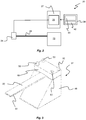
- a rig for testing a composite component 28 is indicated generally at 30.
- the composite component is an elongate specimen that has a rectangular and substantially constant cross section.
- the rig includes a clamp 32 for clamping one end of the composite component.
- the rig further includes a loading fork 34 for applying a reversible load to the component at a position spaced from the clamp 32, and in this example at an opposite end of the component to the end that is clamped.
- the loading fork 34 is connected to a load cell 36.
- the loading fork is directly connected to the load cell, i.e. without the use of hydraulic grips for example.
- the load cell in this example is a load cell of a servo-hydraulic testing machine 37 that communicates with a control unit 38.
- the testing machine and control unit may be considered a control system for controlling the load applied during a test.
- the control unit 38 may comprise any suitable circuitry to cause performance of the methods described herein.
- the control unit may comprise: at least one application specific integrated circuit (ASIC); and/or at least one field programmable gate array (FPGA); and/or single or multi-processor architectures; and/or sequential (Von Neumann)/parallel architectures; and/or at least one programmable logic controllers (PLCs); and/or at least one microprocessor; and/or at least one microcontroller, to perform the methods.
- ASIC application specific integrated circuit
- FPGA field programmable gate array
- PLCs programmable logic controllers
- control unit 38 may comprise at least one processor 40 and at least one memory 42.
- the memory 42 may store a computer program comprising computer readable instructions that, when read by the processor 40, causes performance of the methods described herein.
- the computer program may be software or firmware, or may be a combination of software and firmware.
- the computer program may include a user inputted routine that controls displacement of the loading fork 34.
- the processor 40 may include at least one microprocessor and may comprise a single core processor, or may comprise multiple processor cores (such as a dual core processor or a quad core processor).
- the memory 42 may be any suitable non-transitory computer readable storage medium, data storage device or devices, and may comprise a hard disk and/or solid state memory (such as flash memory).
- the memory 42 may be permanent non-removable memory, or may be removable memory (such as a universal serial bus (USB) flash drive).
- USB universal serial bus
- the control system may be provided separately to the test rig or integrally with the test rig.
- the control system in this example operates in an open loop, but in alternative embodiments the control system may operate in a closed loop.
- the clamp 32 includes a base member 46 and a top member 48.
- the component 28 is clamped between the base member and the top member, in this example screws 50 are used to fixedly secure the top member to the base member and to restrict movement of one end of the component.
- the clamp is made from steel, but any suitable material may be used.
- the component 28 includes a film 51 that simulates a crack that has initiated between the layers of the composite component.
- the loading fork 34 is provided in this example at an opposite end of the component to the clamp 32.
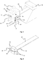
- the rig also includes a first contact arrangement 54 and second contact arrangement 56 that are connected to the component 28 and via which the loading fork applies load to the component.
- the first contact arrangement 54 and the second contact arrangement 56 each include a block 58 and a rod 60.
- Each block 58 is bonded to one of a pair of opposing sides of the component (in this example, one block is bonded to an upper surface of the composite component and one block is bonded to an under surface of the composite component).
- the blocks may be bonded using for example an adhesive.
- the blocks each include a hole extending through the width of the block, and one of the rods is inserted in each hole.
- the rods are dimensioned so as to protrude at each end from the block.
- An elastomer ring 72 is placed around the ends of the rods. In this example the rods are circular in cross section.
- the loading fork 34 includes a first member 62 for contacting one end of the rods 60 and a second member 64 for contacting the other end of the rods 60.
- the elastomer ring 72 is positioned so as be an intermediate member between the rod and the loading fork during loading.
- a third member 63 extends between the first and second member.
- the first, second and third members are integrally formed.
- the loading fork is connected to a rod 65 at the third member and the rod extends to the load cell 36.
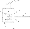
- the first and second members each include a first portion 66 and a second portion 68, the first portion being arranged to contact the rod of the first contact arrangement during loading in one direction and the second portion being arranged to contact the rod of the second contact arrangement during loading in the opposite direction.
- the first and second portions are defined by a window (or cut-out) 70 provided in each of the first and second members.
- the window is rectangular in shape and includes filleted corners.
- the window 70 is dimensioned such that the loading fork 32 contacts only one of the first or second contact arrangements 66, 68 at any one time.
- first direction X in this example downwards
- the first portion of the loading fork contacts the rod of the first contact arrangement and the rod of the second contact arrangement is spaced by a distance 74 from the second portion.
- second portion contacts the rod of the second contact arrangement and the first portion is spaced from the rod of the first contact arrangement by a distance 76.
- the window 70 is also dimensioned so as to be wider than the diameter of the rods of the contact arrangement. In this way sliding of the rods in a direction transverse to the direction of loading is permitted.
- the elongate test specimen is manufactured and includes the film 51.
- the specimen is manufactured to represent the material of the final component, for example the material of a fan blade or a casing of a gas turbine engine.
- full or partial components may be tested, for example the rig could be modified to receive a fan blade for testing.
- one of the blocks 58 of the contact arrangements is bonded to one face of the component (e.g. an upper face of the component) and the other of the blocks of the contact arrangements is bonded to the opposing face of the component (e.g. an under face of the component).
- Testing is commenced by moving the loading fork 32 in opposing directions, up and down in this case.
- the loading fork 32 contacts the rod of the first contact arrangement 54 and there is no contact between the rod of the second contact arrangement 56 and the loading fork.
- Figure 8 when the loading fork is moving upwards the loading fork 32 contacts the rod of the second contact arrangement 56 and there is no contact between the rod of the first contact arrangement 54 and the loading fork.
- the cycles of loading are repeated as many times as required for a given test.
- the displacement 'curve' of the loading fork is actively controlled during each load cycle, using the servo hydraulic test machine 37 (e.g. by varying the crosshead displacement curve).
- a sinusoidal displacement curve In cyclic loading arrangements of the prior art, a simple sinusoidal displacement curve is used.
- a sinusoidal displacement curve will have the steepest slope (hence maximum velocity) when the loading direction changes. This could result in unwanted impact loads on the component.
- the servo-hydraulic testing machine is programmed so that the displacement curve is no longer sinusoidal, but has a modified slope when the load direction changes to reduce the impact speed on the specimen.
- the loading curve of Figure 9 is generally a sinusoidal load curve modified such that when the load where at the range between plus or minus 20% of the maximum load capacity the sinusoidal function is replaced with a linear function of the same monotonicity as the previous sinusoidal part of the function.
- the sign of the gradient corresponds to the sign of the gradient of the sinusoidal function.
- a test specimen is used to perform a compliance calibration. Based on the calibration, the change in compliance during the test indicates crack growth. Additionally or alternatively, the crack growth may be monitored with a camera that takes a picture after a given cycle count. From these pictures the crack growth can be monitored.
- Using the described arrangement means that a load is only ever applied at the loaded end to the component in one direction, because one of the rods does not contact the component. This reduces the risk of the component being pulled open and loading that is not in mode II being applied to the component. As such, the results from the test are improve compared to methods of the prior art.
- the width of the window 70 means that the rods can slide within the window when the component is bent without imparting horizontal loading (other than friction) on the component. This means that there is no need for a "sled" or linear bearing, as is needed with some rigs of the prior art, and as such the rig arrangement is simplified.
- the elastomer rings provided on the ends of the rods further dampen any impact loads and therefore reduce unwanted specimen oscillation.
Landscapes
- Physics & Mathematics (AREA)
- General Physics & Mathematics (AREA)
- Engineering & Computer Science (AREA)
- Chemical & Material Sciences (AREA)
- Aviation & Aerospace Engineering (AREA)
- General Health & Medical Sciences (AREA)
- Biochemistry (AREA)
- Analytical Chemistry (AREA)
- Immunology (AREA)
- Pathology (AREA)
- Life Sciences & Earth Sciences (AREA)
- Health & Medical Sciences (AREA)
- Combustion & Propulsion (AREA)
- Mechanical Engineering (AREA)
- Investigating Strength Of Materials By Application Of Mechanical Stress (AREA)
Claims (11)
- Prüfstand (30) zum Prüfen einer Modus-II-Ermüdung einer Verbundkomponente (28), wobei der Prüfstand Folgendes umfasst:eine Einspanneinheit (32) zum EinEinspannen eines Endes der Komponente, sodass die Komponente in einer Auslegeranordnung eingeklemmt ist;eine Ladegabel (34) zum Anwenden einer Last auf die Komponente;gekennzeichnet durch
eine erste Kontaktanordnung (54), die angeordnet ist, um zum Übertragen einer Last von der Ladegabel auf die Komponente an einer Seite der Komponente befestigt zu sein, und eine zweite Kontaktanordnung (56), die angeordnet ist, um zum Übertragen einer Last von der Ladegabel auf die Komponente an einer gegenüberliegenden Seite der Komponente befestigt zu sein, wobei die erste und die zweite Kontaktanordnung an einer von der Einspanneinheit beabstandeten Position sind;
und
wobei die Ladegabel einen ersten Abschnitt (66) und einen zweiten Abschnitt (68) umfasst, die angeordnet sind, sodass in einer Verwendung, wenn die Ladegabel die Komponente in eine Richtung belastet, der erste Abschnitt die erste Kontaktanordnung berührt und der zweite Abschnitt von der zweiten Kontaktanordnung beabstandet ist, und, wenn die Ladegabel die Komponente in einer gegenüberliegenden Richtung belastet, der erste Abschnitt von der ersten Kontaktanordnung beabstandet ist und der zweite Abschnitt die zweite Kontaktanordnung berührt. - Prüfstand nach Anspruch 1, wobei die Ladegabel ein erstes Glied (62) und ein zweites Glied (64) umfasst, wobei das erste Glied angeordnet ist, um ein Ende der ersten und/oder der zweiten Kontaktanordnung aufzunehmen und das zweite Glied angeordnet ist, um ein gegenüberliegendes Ende der ersten und/oder der zweiten Kontaktanordnung aufzunehmen.
- Prüfstand nach Anspruch 2, wobei das erste Glied ein Fenster (70) beinhaltet, das den ersten Abschnitt und den zweiten Abschnitt zum Kontakt mit der entsprechenden Kontaktanordnung definiert, und wobei das zweite Glied ein Fenster beinhaltet, das den ersten Abschnitt und den zweiten Abschnitt zum Kontakt mit der entsprechenden Kontaktanordnung definiert.
- Prüfstand nach Anspruch 3, wobei das Fenster geformt und dimensioniert ist, um ein Gleiten der ersten und/oder der zweiten Kontaktanordnung in eine Richtung zu ermöglichen, die transversal zur Lastrichtung ist.
- Prüfstand nach einem der vorhergehenden Ansprüche, wobei jede von der ersten und der zweiten Kontaktanordnung ein Blockglied (58) zum Verbinden mit der Verbundkomponente umfasst.
- Prüfstand nach Anspruch 5, wobei jede von der ersten und der zweiten Kontaktanordnung eine Stange (60) umfasst, die in dem Blockglied aufgenommen ist und angeordnet ist, um die Ladegabel zu berühren.
- Prüfstand nach einem der vorhergehenden Ansprüche, wobei der Prüfstand ein Steuersystem (38) beinhaltet, das angeordnet ist, um den Prüfstand so zu betreiben, dass die auf die Komponente angewendete Last durch die Ladegabel nicht sinusförmig ist.
- Prüfstand nach einem der vorhergehenden Ansprüche, wobei ein Elastomer (72) in einem Bereich zwischen der Ladegabel und jeder von der ersten und der zweiten Kontaktanordnung bereitgestellt ist.
- Verfahren zum Prüfen einer Verbundkomponente (28) auf Modus-II-Ermüdung unter Verwendung des Prüfstands (30) nach einem der vorhergehenden Ansprüche, wobei das Verfahren Folgendes umfasst:Einspannen der Komponente in den Prüfstand in einer Auslegeranordnung unter Verwendung der Einspanneinheit (32);Befestigen der ersten und der zweiten Kontaktanordnung (54, 56) an der Verbundkomponente an einer von der Einspanneinheit beabstandeten Position;Bewegen der Ladegabel (34) in eine erste Richtung, um durch ein Berühren der ersten Kontaktanordnung eine Last in eine erste Richtung auf die Komponente anzuwenden und Bewegen der Ladegabel in eine zweite Richtung, um durch Berühren der zweiten Kontaktanordnung eine Last in eine zweite Richtung auf die Komponente anzuwenden.
- Verfahren nach Anspruch 9, wobei das Verfahren ein Bewegen der Ladegabel umfasst, sodass die auf die Komponente angewendete Last nicht sinusförmig ist.
- Verfahren zum Herstellen eines Gasturbinentriebwerks (10), das eine Verbundkomponente umfasst, wobei das Verfahren Folgendes umfasst:Prüfen des zum Bilden der Verbundkomponente verwendeten Materials unter Verwendung eines Verfahrens nach Anspruch 9 oder 10, undwenn das Material die Prüfung besteht, Zusammenbauen der Verbundkomponente in dem Gasturbinentriebwerk.
Applications Claiming Priority (1)
| Application Number | Priority Date | Filing Date | Title |
|---|---|---|---|
| GBGB1517240.6A GB201517240D0 (en) | 2015-09-30 | 2015-09-30 | Rig |
Publications (2)
| Publication Number | Publication Date |
|---|---|
| EP3150985A1 EP3150985A1 (de) | 2017-04-05 |
| EP3150985B1 true EP3150985B1 (de) | 2018-08-01 |
Family
ID=54544306
Family Applications (1)
| Application Number | Title | Priority Date | Filing Date |
|---|---|---|---|
| EP16187400.3A Not-in-force EP3150985B1 (de) | 2015-09-30 | 2016-09-06 | Prüfstand |
Country Status (3)
| Country | Link |
|---|---|
| US (1) | US10401268B2 (de) |
| EP (1) | EP3150985B1 (de) |
| GB (1) | GB201517240D0 (de) |
Families Citing this family (2)
| Publication number | Priority date | Publication date | Assignee | Title |
|---|---|---|---|---|
| CN107314876B (zh) * | 2017-07-04 | 2020-08-28 | 天津航天瑞莱科技有限公司 | 一种用于加载装置底座的连接块结构 |
| US20240353272A1 (en) * | 2023-04-19 | 2024-10-24 | The Boeing Company | Devices and methods for analysis of mechanical and thermal loading of structures, and methods for improving design processes for components of such structures |
Family Cites Families (11)
| Publication number | Priority date | Publication date | Assignee | Title |
|---|---|---|---|---|
| US2699672A (en) * | 1950-10-27 | 1955-01-18 | Robert De S Couch | Impact fatigue testing of packaging materials and containers |
| US4248096A (en) * | 1979-06-18 | 1981-02-03 | Monsanto Research Corporation | Machine for fatigue testing of materials |
| WO2002079774A2 (de) * | 2001-03-16 | 2002-10-10 | Siemens Aktiengesellschaft | Verfahren zur zerstörungsfreien prüfung carbidhaltiger oder in oberflächennähe sulfidierter legierungen |
| US8210051B2 (en) * | 2004-12-03 | 2012-07-03 | General Electric Company | System and method for cyclic testing |
| WO2007084356A2 (en) | 2006-01-13 | 2007-07-26 | Mts Systems Corporation | Duty cycle loading for orthopedic simulator |
| GB0804481D0 (en) * | 2008-03-12 | 2008-04-16 | Rolls Royce Plc | A fatigue test arrangement |
| GB0804488D0 (en) * | 2008-03-12 | 2008-04-16 | Rolls Royce Plc | A vibration test arrangement |
| CN101566518B (zh) * | 2008-04-22 | 2011-06-08 | 深圳富泰宏精密工业有限公司 | 测试装置 |
| CN101464240A (zh) * | 2009-01-14 | 2009-06-24 | 北京航空航天大学 | 涡轮盘/叶片榫接高温复合疲劳加载方法及其装置 |
| CA2797639A1 (en) | 2010-01-19 | 2011-07-28 | Vestas Wind Systems A/S | Systems and methods for performing structural tests on wind turbine blades |
| CH702812B1 (de) * | 2010-03-10 | 2014-09-30 | George Cant | Einrichtung zur Bestimmung von Materialeigenschaften von Snowboards oder Ski. |
-
2015
- 2015-09-30 GB GBGB1517240.6A patent/GB201517240D0/en not_active Ceased
-
2016
- 2016-09-06 EP EP16187400.3A patent/EP3150985B1/de not_active Not-in-force
- 2016-09-06 US US15/257,580 patent/US10401268B2/en not_active Expired - Fee Related
Also Published As
| Publication number | Publication date |
|---|---|
| US20170089816A1 (en) | 2017-03-30 |
| GB201517240D0 (en) | 2015-11-11 |
| EP3150985A1 (de) | 2017-04-05 |
| US10401268B2 (en) | 2019-09-03 |
Similar Documents
| Publication | Publication Date | Title |
|---|---|---|
| Nijssen et al. | Fatigue as a design driver for composite wind turbine blades | |
| Yao et al. | Vibration characteristics of pre-twisted rotating Ti-SiC composite airfoil blade | |
| Provenza et al. | Aeromechanical response of a distortion-tolerant boundary layer ingesting fan | |
| GB2551629B (en) | A composite component | |
| US8197190B2 (en) | Lever for rotating a turbomachine variable-pitch stator vane about its pivot | |
| EP3287629A1 (de) | Gasturbinentriebwerk-lebensdauerüberwachungssystem mit wellendrehzahlsensoren | |
| EP2551094B1 (de) | Verbindungs- und Heftreparatur für delaminierten Verbundstoff | |
| CN106226015A (zh) | 一种叶片‑轮盘耦合振动的试验装置 | |
| US10401268B2 (en) | Rig | |
| CN111350693A (zh) | 用于复合风扇叶片的预张紧和保持结构 | |
| EP3543467A1 (de) | Schaufelblatt in verbundbauweise mit einzellage mit einer vielzahl an faserwinkeln und zugehöriges herstellungsverfahren | |
| Provenza et al. | Aeromechanical Response of a Distortion Tolerant Boundary Layer Ingesting Fan | |
| CN111238804B (zh) | 航空发动机转子的超转破裂试验的试验件构型方法 | |
| CN104458236A (zh) | 一种增压器涡轮心部强度加速试验验证方法 | |
| Sinha et al. | Dynamic loading on turbofan blades due to bird-strike | |
| EP2955005B1 (de) | Verbundstruktur und verfahren zur herstellung davon | |
| CN112179794A (zh) | 一种复合材料叶片榫根疲劳强度测试装置 | |
| Li et al. | Simulation of fatigue failure in composite axial compressor blades | |
| Kato et al. | Research and development of a high performance axial compressor | |
| US7400994B2 (en) | Method and test component for rotatable disc parts | |
| US10385869B2 (en) | Composite component | |
| Stockton et al. | Design and Manufacturing of Composite Propellers for SUAS | |
| Sarıten et al. | Burst speed prediction of impellers with critical strain criteria | |
| Li et al. | Static, dynamic and failure behavior of a novel axial composite impeller for water chiller | |
| Rao | Rotor dynamics of aircraft gas turbine engines |
Legal Events
| Date | Code | Title | Description |
|---|---|---|---|
| PUAI | Public reference made under article 153(3) epc to a published international application that has entered the european phase |
Free format text: ORIGINAL CODE: 0009012 |
|
| STAA | Information on the status of an ep patent application or granted ep patent |
Free format text: STATUS: THE APPLICATION HAS BEEN PUBLISHED |
|
| AK | Designated contracting states |
Kind code of ref document: A1 Designated state(s): AL AT BE BG CH CY CZ DE DK EE ES FI FR GB GR HR HU IE IS IT LI LT LU LV MC MK MT NL NO PL PT RO RS SE SI SK SM TR |
|
| AX | Request for extension of the european patent |
Extension state: BA ME |
|
| STAA | Information on the status of an ep patent application or granted ep patent |
Free format text: STATUS: REQUEST FOR EXAMINATION WAS MADE |
|
| 17P | Request for examination filed |
Effective date: 20170928 |
|
| RBV | Designated contracting states (corrected) |
Designated state(s): AL AT BE BG CH CY CZ DE DK EE ES FI FR GB GR HR HU IE IS IT LI LT LU LV MC MK MT NL NO PL PT RO RS SE SI SK SM TR |
|
| GRAP | Despatch of communication of intention to grant a patent |
Free format text: ORIGINAL CODE: EPIDOSNIGR1 |
|
| STAA | Information on the status of an ep patent application or granted ep patent |
Free format text: STATUS: GRANT OF PATENT IS INTENDED |
|
| RIC1 | Information provided on ipc code assigned before grant |
Ipc: B23P 19/04 20060101ALI20180410BHEP Ipc: G01M 15/14 20060101ALI20180410BHEP Ipc: G01N 3/32 20060101ALI20180410BHEP Ipc: G01M 5/00 20060101AFI20180410BHEP |
|
| INTG | Intention to grant announced |
Effective date: 20180514 |
|
| GRAS | Grant fee paid |
Free format text: ORIGINAL CODE: EPIDOSNIGR3 |
|
| GRAA | (expected) grant |
Free format text: ORIGINAL CODE: 0009210 |
|
| STAA | Information on the status of an ep patent application or granted ep patent |
Free format text: STATUS: THE PATENT HAS BEEN GRANTED |
|
| AK | Designated contracting states |
Kind code of ref document: B1 Designated state(s): AL AT BE BG CH CY CZ DE DK EE ES FI FR GB GR HR HU IE IS IT LI LT LU LV MC MK MT NL NO PL PT RO RS SE SI SK SM TR |
|
| REG | Reference to a national code |
Ref country code: GB Ref legal event code: FG4D |
|
| REG | Reference to a national code |
Ref country code: CH Ref legal event code: EP Ref country code: AT Ref legal event code: REF Ref document number: 1024866 Country of ref document: AT Kind code of ref document: T Effective date: 20180815 |
|
| REG | Reference to a national code |
Ref country code: IE Ref legal event code: FG4D |
|
| REG | Reference to a national code |
Ref country code: DE Ref legal event code: R096 Ref document number: 602016004488 Country of ref document: DE |
|
| REG | Reference to a national code |
Ref country code: FR Ref legal event code: PLFP Year of fee payment: 3 |
|
| REG | Reference to a national code |
Ref country code: NL Ref legal event code: MP Effective date: 20180801 |
|
| REG | Reference to a national code |
Ref country code: LT Ref legal event code: MG4D |
|
| REG | Reference to a national code |
Ref country code: AT Ref legal event code: MK05 Ref document number: 1024866 Country of ref document: AT Kind code of ref document: T Effective date: 20180801 |
|
| PG25 | Lapsed in a contracting state [announced via postgrant information from national office to epo] |
Ref country code: LT Free format text: LAPSE BECAUSE OF FAILURE TO SUBMIT A TRANSLATION OF THE DESCRIPTION OR TO PAY THE FEE WITHIN THE PRESCRIBED TIME-LIMIT Effective date: 20180801 Ref country code: FI Free format text: LAPSE BECAUSE OF FAILURE TO SUBMIT A TRANSLATION OF THE DESCRIPTION OR TO PAY THE FEE WITHIN THE PRESCRIBED TIME-LIMIT Effective date: 20180801 Ref country code: RS Free format text: LAPSE BECAUSE OF FAILURE TO SUBMIT A TRANSLATION OF THE DESCRIPTION OR TO PAY THE FEE WITHIN THE PRESCRIBED TIME-LIMIT Effective date: 20180801 Ref country code: NL Free format text: LAPSE BECAUSE OF FAILURE TO SUBMIT A TRANSLATION OF THE DESCRIPTION OR TO PAY THE FEE WITHIN THE PRESCRIBED TIME-LIMIT Effective date: 20180801 Ref country code: AT Free format text: LAPSE BECAUSE OF FAILURE TO SUBMIT A TRANSLATION OF THE DESCRIPTION OR TO PAY THE FEE WITHIN THE PRESCRIBED TIME-LIMIT Effective date: 20180801 Ref country code: IS Free format text: LAPSE BECAUSE OF FAILURE TO SUBMIT A TRANSLATION OF THE DESCRIPTION OR TO PAY THE FEE WITHIN THE PRESCRIBED TIME-LIMIT Effective date: 20181201 Ref country code: BG Free format text: LAPSE BECAUSE OF FAILURE TO SUBMIT A TRANSLATION OF THE DESCRIPTION OR TO PAY THE FEE WITHIN THE PRESCRIBED TIME-LIMIT Effective date: 20181101 Ref country code: GR Free format text: LAPSE BECAUSE OF FAILURE TO SUBMIT A TRANSLATION OF THE DESCRIPTION OR TO PAY THE FEE WITHIN THE PRESCRIBED TIME-LIMIT Effective date: 20181102 Ref country code: NO Free format text: LAPSE BECAUSE OF FAILURE TO SUBMIT A TRANSLATION OF THE DESCRIPTION OR TO PAY THE FEE WITHIN THE PRESCRIBED TIME-LIMIT Effective date: 20181101 Ref country code: SE Free format text: LAPSE BECAUSE OF FAILURE TO SUBMIT A TRANSLATION OF THE DESCRIPTION OR TO PAY THE FEE WITHIN THE PRESCRIBED TIME-LIMIT Effective date: 20180801 Ref country code: PL Free format text: LAPSE BECAUSE OF FAILURE TO SUBMIT A TRANSLATION OF THE DESCRIPTION OR TO PAY THE FEE WITHIN THE PRESCRIBED TIME-LIMIT Effective date: 20180801 |
|
| PG25 | Lapsed in a contracting state [announced via postgrant information from national office to epo] |
Ref country code: AL Free format text: LAPSE BECAUSE OF FAILURE TO SUBMIT A TRANSLATION OF THE DESCRIPTION OR TO PAY THE FEE WITHIN THE PRESCRIBED TIME-LIMIT Effective date: 20180801 Ref country code: LV Free format text: LAPSE BECAUSE OF FAILURE TO SUBMIT A TRANSLATION OF THE DESCRIPTION OR TO PAY THE FEE WITHIN THE PRESCRIBED TIME-LIMIT Effective date: 20180801 Ref country code: HR Free format text: LAPSE BECAUSE OF FAILURE TO SUBMIT A TRANSLATION OF THE DESCRIPTION OR TO PAY THE FEE WITHIN THE PRESCRIBED TIME-LIMIT Effective date: 20180801 |
|
| PG25 | Lapsed in a contracting state [announced via postgrant information from national office to epo] |
Ref country code: IT Free format text: LAPSE BECAUSE OF FAILURE TO SUBMIT A TRANSLATION OF THE DESCRIPTION OR TO PAY THE FEE WITHIN THE PRESCRIBED TIME-LIMIT Effective date: 20180801 Ref country code: MC Free format text: LAPSE BECAUSE OF FAILURE TO SUBMIT A TRANSLATION OF THE DESCRIPTION OR TO PAY THE FEE WITHIN THE PRESCRIBED TIME-LIMIT Effective date: 20180801 Ref country code: EE Free format text: LAPSE BECAUSE OF FAILURE TO SUBMIT A TRANSLATION OF THE DESCRIPTION OR TO PAY THE FEE WITHIN THE PRESCRIBED TIME-LIMIT Effective date: 20180801 Ref country code: ES Free format text: LAPSE BECAUSE OF FAILURE TO SUBMIT A TRANSLATION OF THE DESCRIPTION OR TO PAY THE FEE WITHIN THE PRESCRIBED TIME-LIMIT Effective date: 20180801 Ref country code: CZ Free format text: LAPSE BECAUSE OF FAILURE TO SUBMIT A TRANSLATION OF THE DESCRIPTION OR TO PAY THE FEE WITHIN THE PRESCRIBED TIME-LIMIT Effective date: 20180801 Ref country code: RO Free format text: LAPSE BECAUSE OF FAILURE TO SUBMIT A TRANSLATION OF THE DESCRIPTION OR TO PAY THE FEE WITHIN THE PRESCRIBED TIME-LIMIT Effective date: 20180801 |
|
| REG | Reference to a national code |
Ref country code: DE Ref legal event code: R097 Ref document number: 602016004488 Country of ref document: DE |
|
| PG25 | Lapsed in a contracting state [announced via postgrant information from national office to epo] |
Ref country code: DK Free format text: LAPSE BECAUSE OF FAILURE TO SUBMIT A TRANSLATION OF THE DESCRIPTION OR TO PAY THE FEE WITHIN THE PRESCRIBED TIME-LIMIT Effective date: 20180801 Ref country code: SM Free format text: LAPSE BECAUSE OF FAILURE TO SUBMIT A TRANSLATION OF THE DESCRIPTION OR TO PAY THE FEE WITHIN THE PRESCRIBED TIME-LIMIT Effective date: 20180801 Ref country code: SK Free format text: LAPSE BECAUSE OF FAILURE TO SUBMIT A TRANSLATION OF THE DESCRIPTION OR TO PAY THE FEE WITHIN THE PRESCRIBED TIME-LIMIT Effective date: 20180801 |
|
| PLBE | No opposition filed within time limit |
Free format text: ORIGINAL CODE: 0009261 |
|
| STAA | Information on the status of an ep patent application or granted ep patent |
Free format text: STATUS: NO OPPOSITION FILED WITHIN TIME LIMIT |
|
| REG | Reference to a national code |
Ref country code: BE Ref legal event code: MM Effective date: 20180930 |
|
| REG | Reference to a national code |
Ref country code: IE Ref legal event code: MM4A |
|
| PG25 | Lapsed in a contracting state [announced via postgrant information from national office to epo] |
Ref country code: LU Free format text: LAPSE BECAUSE OF NON-PAYMENT OF DUE FEES Effective date: 20180906 |
|
| 26N | No opposition filed |
Effective date: 20190503 |
|
| PG25 | Lapsed in a contracting state [announced via postgrant information from national office to epo] |
Ref country code: IE Free format text: LAPSE BECAUSE OF NON-PAYMENT OF DUE FEES Effective date: 20180906 |
|
| PG25 | Lapsed in a contracting state [announced via postgrant information from national office to epo] |
Ref country code: BE Free format text: LAPSE BECAUSE OF NON-PAYMENT OF DUE FEES Effective date: 20180930 Ref country code: SI Free format text: LAPSE BECAUSE OF FAILURE TO SUBMIT A TRANSLATION OF THE DESCRIPTION OR TO PAY THE FEE WITHIN THE PRESCRIBED TIME-LIMIT Effective date: 20180801 |
|
| PG25 | Lapsed in a contracting state [announced via postgrant information from national office to epo] |
Ref country code: MT Free format text: LAPSE BECAUSE OF NON-PAYMENT OF DUE FEES Effective date: 20180906 |
|
| PG25 | Lapsed in a contracting state [announced via postgrant information from national office to epo] |
Ref country code: TR Free format text: LAPSE BECAUSE OF FAILURE TO SUBMIT A TRANSLATION OF THE DESCRIPTION OR TO PAY THE FEE WITHIN THE PRESCRIBED TIME-LIMIT Effective date: 20180801 |
|
| PG25 | Lapsed in a contracting state [announced via postgrant information from national office to epo] |
Ref country code: PT Free format text: LAPSE BECAUSE OF FAILURE TO SUBMIT A TRANSLATION OF THE DESCRIPTION OR TO PAY THE FEE WITHIN THE PRESCRIBED TIME-LIMIT Effective date: 20180801 |
|
| REG | Reference to a national code |
Ref country code: CH Ref legal event code: PL |
|
| PG25 | Lapsed in a contracting state [announced via postgrant information from national office to epo] |
Ref country code: CY Free format text: LAPSE BECAUSE OF FAILURE TO SUBMIT A TRANSLATION OF THE DESCRIPTION OR TO PAY THE FEE WITHIN THE PRESCRIBED TIME-LIMIT Effective date: 20180801 Ref country code: MK Free format text: LAPSE BECAUSE OF NON-PAYMENT OF DUE FEES Effective date: 20180801 Ref country code: HU Free format text: LAPSE BECAUSE OF FAILURE TO SUBMIT A TRANSLATION OF THE DESCRIPTION OR TO PAY THE FEE WITHIN THE PRESCRIBED TIME-LIMIT; INVALID AB INITIO Effective date: 20160906 |
|
| PG25 | Lapsed in a contracting state [announced via postgrant information from national office to epo] |
Ref country code: CH Free format text: LAPSE BECAUSE OF NON-PAYMENT OF DUE FEES Effective date: 20190930 Ref country code: LI Free format text: LAPSE BECAUSE OF NON-PAYMENT OF DUE FEES Effective date: 20190930 |
|
| PGFP | Annual fee paid to national office [announced via postgrant information from national office to epo] |
Ref country code: FR Payment date: 20210927 Year of fee payment: 6 |
|
| PGFP | Annual fee paid to national office [announced via postgrant information from national office to epo] |
Ref country code: DE Payment date: 20210929 Year of fee payment: 6 Ref country code: GB Payment date: 20210927 Year of fee payment: 6 |
|
| REG | Reference to a national code |
Ref country code: DE Ref legal event code: R119 Ref document number: 602016004488 Country of ref document: DE |
|
| GBPC | Gb: european patent ceased through non-payment of renewal fee |
Effective date: 20220906 |
|
| P01 | Opt-out of the competence of the unified patent court (upc) registered |
Effective date: 20230528 |
|
| PG25 | Lapsed in a contracting state [announced via postgrant information from national office to epo] |
Ref country code: FR Free format text: LAPSE BECAUSE OF NON-PAYMENT OF DUE FEES Effective date: 20220930 Ref country code: DE Free format text: LAPSE BECAUSE OF NON-PAYMENT OF DUE FEES Effective date: 20230401 |
|
| PG25 | Lapsed in a contracting state [announced via postgrant information from national office to epo] |
Ref country code: GB Free format text: LAPSE BECAUSE OF NON-PAYMENT OF DUE FEES Effective date: 20220906 |